Embed Size (px)
Citation preview

© 2008 Cisco Systems, Inc. All rights reserved. Cisco ConfidentialPresentation_ID 1
IPoDWDM, 40G, 100G and beyond
Dirk Schroetter, Consulting Systems Engineer

© 2008 Cisco Systems, Inc. All rights reserved. Cisco ConfidentialPresentation_ID 2
Agenda
IPoDWDM overview
Beyond the Basics – Proactive Protection
Moving to 40G, 100G and beyond
Q&A

© 2008 Cisco Systems, Inc. All rights reserved. Cisco ConfidentialPresentation_ID 3
IPoDWDM introduction

© 2008 Cisco Systems, Inc. All rights reserved. Cisco ConfidentialPresentation_ID 4
Basic idea of IPoDWDM on one slide
Lower CapEx
Elimination of OEOs
Lower OpEx
Space, power,
management
Enhanced resiliency
Fewer active
components
Investment protection
40G and beyond,
interoperability over
existing 10G systems
Before
Router ROADMTransponderCross-connect
WDM Transponders Integrated into Router
Router ROADM
DW
DM
I/F

© 2008 Cisco Systems, Inc. All rights reserved. Cisco ConfidentialPresentation_ID 5
CapEx / OpEx / Green: Real-world example
3 racks
IPoDWDMmodel
12 racks
DWDMmodel
PoP1Max. Power
(W)Average Power
(W)
DWDM 18,084.1 11,913.73
IPoDWDM 4,250.2 2,813.86
Power Savings (W) 13,833.9 9,099.87
Energy Cost Savings (€/yr/PoP) 15,391.32 9,894.42
Power consumption traditional vs IPoDWDM
Only Transmission equipment (DWDM+Transponders) shown. Router HW not shown. Except using IPoDWDM router line cards instead oftraditional ones, there’s no difference on the routers. Energy cost savings based on average price for industry of € 0.1255/kWh (04/2008)

© 2008 Cisco Systems, Inc. All rights reserved. Cisco ConfidentialPresentation_ID 6
Reliability comparisonImproving MTBF through IPoDWDM
Predicted MTBF values
600000(1)
TXPIP
IP
240000(1)440000(1)
TXP IP
IP
Transponder Case: yearly unavailability 7,7 minutes
IPoDWDM case: yearly unavailability 3,3 minutes

© 2008 Cisco Systems, Inc. All rights reserved. Cisco ConfidentialPresentation_ID 7
IPoDWDM Solution Elements
IPoDWDM SolutionInterfaces
•Eliminates Transponders from DWDM Systems
• Increase Reliability•Available on CRS-1, 12k (IOS only) and 7600
Virtual Transponders
•Allow for either integrated or separated management of IPoDWDM
•Solution element to overcome some pushback from transport department
Proactive Protection
•New feature allowing for zero to near-zero packet loss recovery
•Can lead to massive savings in bandwidth when used to rearchitectprotection
CapEx/OpEx/Green
•Eliminates DWDM shelves, transponders
•Saves energy on power, cooling
•Saves space•Lead-in to ―Green message‖
Foundation for ―Intelligent Photonic Layer‖
•Ties the IP Layer to DWDM system overhaul
•Can use ―Optical Control Plane‖ to shift discussion on Optical from price to features
IPoDWDM is not just the interfaces

© 2008 Cisco Systems, Inc. All rights reserved. Cisco ConfidentialPresentation_ID 8
IPoDWDM Interfaces
Interface AvailabilityCRS-1
• 1-port 40G WDMPHY
• Two versions available
• ODB and DPSK+ modulation
• 4-port 10GE WDMPHY
12000 Series
• 1-port 10GE WDMPHY
• Currently only supported under IOS, not IOS-XR
Cisco 7600
• 2-port 10GE WDMPHY
• 4- port 10GE WDMPHY
• Uses pluggable optics
• Available Q1CY09

© 2008 Cisco Systems, Inc. All rights reserved. Cisco ConfidentialPresentation_ID 9
Segmented Administration
Respect organization boundaries
Data/transport group separation
Restrict users through rule-based access control
Segmented Administration
Data Group
Transport Group
Virtual Transponders
Integrated Administration
End-to-end provisioning
Better trouble shooting
Reduced complexity
Integrated Administration
Router DWDM Transport
WDMI/F
WDMI/F
DWDM TransportRouter
WDMI/F
WDMI/F

© 2008 Cisco Systems, Inc. All rights reserved. Cisco ConfidentialPresentation_ID 10
VTs: Reintroducing a clear demarcation
Alarm
EMS
TranspondersIn Shelves
TL-1/CORBA
DWDM Main Controller
w/ Info Model Database
Config
Traditional Network
Transponder Representation
in Info Model
Comm Inside the NE (IPC)
Alarm
EMS
DWDM Router Interfaces
TL-1/CORBA/XML
Config
DWDM Main Controller
w/ Info Model Database
Virtual Transponder
Representation in Info Model
LMP
IPoDWDM: Can Be Managed w/out Significant Changes

© 2008 Cisco Systems, Inc. All rights reserved. Cisco ConfidentialPresentation_ID 11
Beyond the basics –Proactive Protection

© 2008 Cisco Systems, Inc. All rights reserved. Cisco ConfidentialPresentation_ID 12
BFD lostHELLOs lost
Factors influencing Failure Detection TimeTx
Rx
Rx
Tx
Tx
Rx
Rx
Tx
Tx
Rx
Rx
Tx
Tx
Rx
Rx
Tx
Hello
Cut
Fiber Cut
AIS
Transport System generates AIS
TX off Time to Detect ≈ 0 ms
BER
BER increasing
SD
Transport system asserts SD
Router sees IF down -> recalculate
No signal of SD except for POS
Time to Detect ??? ms
BFD
n HELLO packets lost -> recalculate
Time to Detect > 15 ms
Time to Detect > 1 s
BFD packets lost -> recalculate
Conclusion: Hard errors are easy to detect, dribble conditions are hard

© 2008 Cisco Systems, Inc. All rights reserved. Cisco ConfidentialPresentation_ID 13
How to Protect Core Packet Traffic?
Working optical path
(VC-n, ODU-n, or l)
Dedicated or Shared
protection optical path
Conclusion: Optical layer protection requires additional bandwidth (30% typical in shared mesh architectures) and electrical switches
Working
Protect

© 2008 Cisco Systems, Inc. All rights reserved. Cisco ConfidentialPresentation_ID 14
How to Protect Core Packet Traffic?
Working LSP path
Shared protection
via LSP tunnel
Conclusion: Protection at the packet level is as fast w FRR and supports a more cost effective architecture
Empty
Low pri

© 2008 Cisco Systems, Inc. All rights reserved. Cisco ConfidentialPresentation_ID 15
Advanced Protection Conclusions from Network Study
Conclusions:
1. IP/MPLS layer protection is much more bandwidth efficient if low priority traffic is preempted – see 1st row in above table
Assumption: 30% traffic must be protected, the rest can be restored slowly
2. IP/MPLS protection is still very effective if low priority traffic is unprotected but not preempted – see 2nd and 3rd rows in above table
3. The CAPEX for IP/MPLS protection is within 10% of the most efficient TDM protection when WDMPOS interfaces are used
4. The CAPEX for IP/MPLS protection is 47% of the most efficient TDM shared protection when WDMPHY interfaces are used
Model 10G Channels
IP Load Share 81
IP Shared HP Protection Bandwidth 90
IP Reserved HP Protection Bandwidth 97
TDM Shared Protection 106
TDM 1+1 Protection 111

© 2008 Cisco Systems, Inc. All rights reserved. Cisco ConfidentialPresentation_ID 16
Timing IP/MPLS Convergence
t1t3 t4
Rero
uting
Tim
e
RX (%)
time
100
t0
t1 t2 t3 t4
Failu
re
Dete
ction
Tim
e
Rero
uting
Tim
e
Conve
rgin
g
Tim
e
RX (%)
time
100
―Reactive‖ Protection
Proactive Protection
Failure Detection Time:Time Between Failure of Link Until Neighbor Is Declared ―Down‖
Rereouting Time: Time Between „‖Neighbor Down‖ Event and Recalculation of Routes
Converging Time: Time Between Recalculation of Routes Until All Routers in Routing Domain Have the Same Routing Database
Proactive Protection
Focus

© 2008 Cisco Systems, Inc. All rights reserved. Cisco ConfidentialPresentation_ID 17
IP FRR Test Results
Protection Type Fault Type
Convergence Time (ms)
Highest Lowest Average
Proactive Optical Switch 11,50 11,18 11,37
Proactive Noise Injection 0,02 0 0,00
Proactive Fiber Pull (Tx) 25,48 0 12,39
Proactive PMD-Injection 0,08 0 0,02
Standard Optical Switch 11,54 11,37 11,43
Standard Noise Injection 7404 1193 4305
Standard Fiber Pull (Tx) 25,93 12,50 20,19
Standard PMD-Injection 129,62 122,51 125,90

© 2008 Cisco Systems, Inc. All rights reserved. Cisco ConfidentialPresentation_ID 18
ISIS Fast Convergence Test Results
Protection Type Fault Type
Convergence Time (ms)
C(500) C(1000) C(1)
Proactive Optical Switch 170 220 163
Proactive Slow Noise Injection 3 12 0
Proactive Fast Noise Injection 3 9 0
Standard Optical Switch 180 205 159
Standard Slow Noise Injection 2990 3035 2880
Standard Fast Noise Injection 596 620 540

© 2008 Cisco Systems, Inc. All rights reserved. Cisco ConfidentialPresentation_ID 19
MPLS FRR ISIS Test Results
Protection Type Fault Type
Convergence Time (ms)
Highest Lowest Average
Proactive Optical Switch 11,48 10,99 11,24
Proactive Noise Injection 0,12 0 0,05
Proactive Fiber Pull 14,95 0 4,95
Standard Optical Switch 11,61 11,16 11,32
Standard Noise Injection 2852 2602 2727
Standard Fiber Pull 83,84 13,49 37,63

© 2008 Cisco Systems, Inc. All rights reserved. Cisco ConfidentialPresentation_ID 20
Moving to 40G, 100G and beyond

© 2008 Cisco Systems, Inc. All rights reserved. Cisco ConfidentialPresentation_ID 21
IEEE 802.3ba Objectives• Support full-duplex operation only
• Preserve the 802.3 / Ethernet frame format utilizing the 802.3 MAC
• Preserve minimum and maximum FrameSizeof current 802.3 standard
• Support a BER better than or equal to 10-12 at the MAC/PLS service interface
• Provide appropriate support for OTN
• Support a MAC data rate of 40 Gb/s
• Provide Physical Layer specifications which support: 40 Gb/s
–at least 100m on OM3 MMF
–at least 10m over a copper cable assembly
–at least 1m over a backplane
• Support a MAC data rate of 100 Gb/s
• Provide Physical Layer specifications which support:
–at least 40km on SMF
–at least 10km on SMF (likely to become 2-4km)
–at least 100m on OM3 MMF
–at least 10m over a copper cable assembly

© 2008 Cisco Systems, Inc. All rights reserved. Cisco ConfidentialPresentation_ID 22
40GbE / 100GbE solution space
Source: Based on IEEE HSSG contribution by Drew Perkins Sept. 2006
• 100 GBd not implementable in current CMOS
Costly alternatives are SiGe or InP
• Optical impairments (PMD, CD, ...) ~ square of symbol rate
May use different modulation type (e.g. DQPSK)
• Advantageous for DWDM transmission wrt spectral efficiency
• How to map that into SONET/SDH/OTN?
PCS mapping changes
• Alleviates need for 10 x symbol rate
25 GBd (= 4 x 25 Gbit) under discussion for a 2 x serial PHY
• Not yet been used for optical transmission on a large scale
• Well understood technology
• Can reuse 10GE PMDs
• VCSEL (for MMF) arrays can overcome cost issue
10G VCSELs just becoming available
Reliability concerns for arrays
In production for 850nm - 1310nm and
1550nm still very early
• Poor spectral efficiency for WAN
• Requires some form of descew like EFM
• Has the strongest support in HSSG

© 2008 Cisco Systems, Inc. All rights reserved. Cisco ConfidentialPresentation_ID 23
Key concept for 40/100GbE: Virtual Lanes
Split 66B/64B stream into a number of Virtual Lanes
The 40/100GB are then Bit Muxed over 1/4/10 physical lanes
Electrical and optical scew will rearrange bits @ Rx but Virtual Lane Bit order is preserved
MAC data rate preserved
Alignment protocol reuses some BW from IPG
© 2008 Cisco Systems, Inc. All rights reserved. Cisco ConfidentialPresentation_ID 24
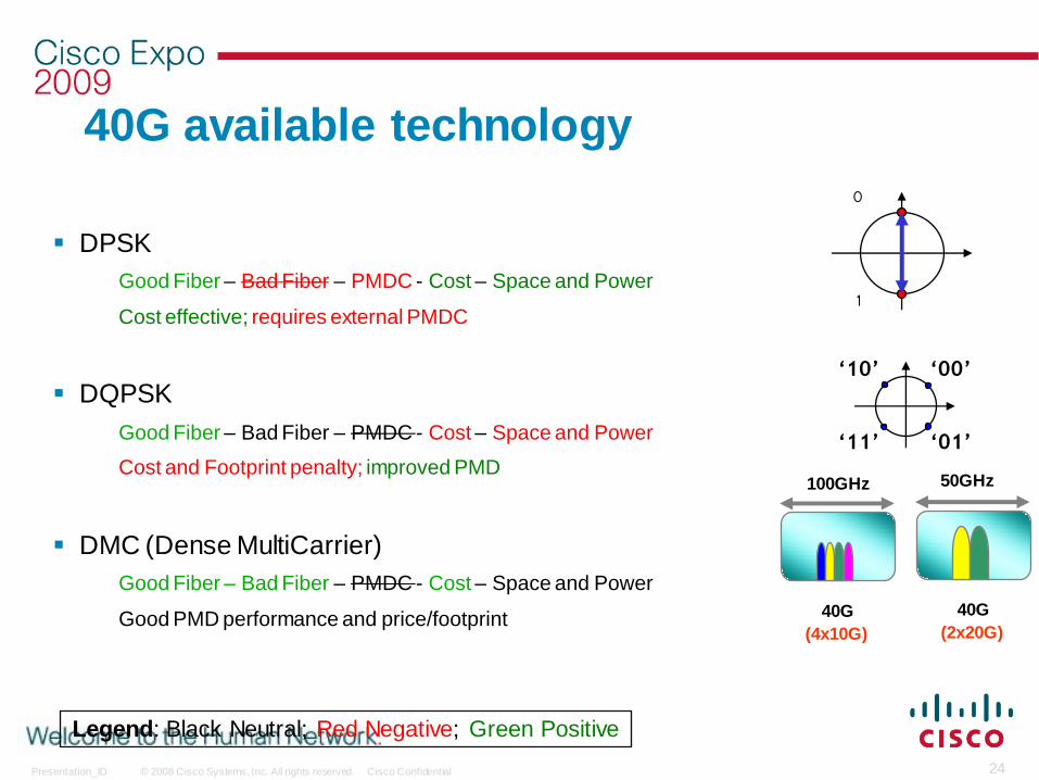
40G available technology
DPSK
Good Fiber – Bad Fiber – PMDC - Cost – Space and Power
Cost effective; requires external PMDC
DQPSK
Good Fiber – Bad Fiber – PMDC - Cost – Space and Power
Cost and Footprint penalty; improved PMD
DMC (Dense MultiCarrier)
Good Fiber – Bad Fiber – PMDC - Cost – Space and Power
Good PMD performance and price/footprint
100GHz
40G
(4x10G)
40G
(2x20G)
50GHz
0
1
‘10’
‘11’
‘00’
‘01’
Legend: Black Neutral; Red Negative; Green Positive

© 2008 Cisco Systems, Inc. All rights reserved. Cisco ConfidentialPresentation_ID 25
PolMux SolutionDual Polarization QPSK with Coherent Detection
Transmitter: Two QPSK signals are muxed in polarization
+ 40Gb/s
‘10’
‘11’
‘00’
‘01’
20Gb/s
‘10’
‘11’
‘00’
‘01’
20Gb/s
Laser
10Gb/s
QPSK1 Modulator
10Gb/s
Same Optical Bandwitdh as a 10G NRZ!!
40Gb/s = 10Gbaud
10Gb/s
QPSK2 Modulator
10Gb/s
10Gbaud signal propagate into the fiber as a 10Gb/s signal

© 2008 Cisco Systems, Inc. All rights reserved. Cisco ConfidentialPresentation_ID 26
Parameter 10G (NRZ)
DPSK DQPSK Multi-Carrier DP-QPSK
w/o PMDC w/PMDC w/o PMDC w/PMDC 4x10G(ODB)
2x20G (DQPSK)
B-to-B OSNR (dB) 5 8.5 8.5 8.5 8.5 13 8.5 4
50GHz Compatibility Yes Yes Yes Yes Yes No Yes Yes
CD Robustness (ps/nm)
- 1dB of OSNR margin
- 2dB of OSNR margin
+/-500
+/-800
+/-650 +/-650 +/-650 +/-650
+/-2,000
+/-3,000
+/-500
+/-800
+/-4,000
PMD Robustness (ps)
- 1dB of OSNR margin
- 2dB of OSNR margin
10
13
2.5
3.5 8
5
8 15
10
13
10
13
> 25
Complexity Low Low Medium Medium Low Medium High
Cost 100% 142% 141% 181% 102% 146% 118%
Technology Comparison

© 2008 Cisco Systems, Inc. All rights reserved. Cisco ConfidentialPresentation_ID 27
40GbE Variants
40GbEMAC
BackplaneVery Short Reach
Data CenterShort Reach
100m
CampusIntermediate Reach
10km
4x10G Copper40GBASE-KR4
4x10G Copper40GBASE-CX4
4x10G Ribbon40GBASE-SR4
4x10G40GBASE-LR4
Long Haul
ODU3
Current Focus of IEEE HSSG
Approaches: Optimized for Area of Implementation
38.9GbE MAC with 64/66 coding40.0GbE MAC with 64/66 coding

© 2008 Cisco Systems, Inc. All rights reserved. Cisco ConfidentialPresentation_ID 28
Expectation of 100Gig WDMPHY
100 Gig and above rates must meet minimum requirements:
Target 10 Gig distances—1600–2000 Km reach
Not simply a Greenfield technology, but plug and play over existing 10Gig networks
Must be as open as possible, operate over third party DWDM networks
Must operate over both 100GHz as well as 50GHz spacings
Must be at a competitive cost point
Power and footprint must be reasonable, can not redesign Router/ transport shelf due to blade
To achieve must leverage/control:
1. Optical Impairments
2. Modulations Schemes
Same as 40Gig Requirements!!

© 2008 Cisco Systems, Inc. All rights reserved. Cisco ConfidentialPresentation_ID 29
100GbE Variants
100GbEMAC
Data CentersShort Reach
<100m MMF or<10m Copper
Campus NetworksIntermediate Reach
10km SMF
MetroLong Reach
10-40km
10x10G100GBASE-CR10
10x10G MMF100GBASE-SR10
10x10G5x20G4x25G100GBASE-LR4
4x25G100GBASE-ER4
Long Haul
Serial 100GODU2-11vODU3-3v
ODU4
Current Focus of IEEE HSSG
Approaches: Optimized for Area of Implementation
100GbE MAC with 64/66 coding=> 103Gbps of data

© 2008 Cisco Systems, Inc. All rights reserved. Cisco ConfidentialPresentation_ID 30
100GE and the ITU ITU agreed to optimize new OTU4 rate for 100GE transport
Industry appears to have learnt its lesson from 10GE (i.e. LAN/WAN PHY)
Ideally want one mapping, one FEC and one modulation scheme !!!
some resistance from traditional transport vendors
Transmission requirements are the same as 40G:
Must work over existing, installed DWDM common equipment;
Support 50GHz DWDM channel spacing;
Full band tunable lasers on 50GHz ITU grid
Optical reach of ≥ 1,500km;
Chromatic dispersion tolerance of >±800ps/nm;
Polarization Mode Dispersion tolerance of > 10ps (mean DGD);
Must be ―plug and play‖ and installable by existing field technicians
40G was the first commercial application for advanced modulation:
100G will build on similar approaches

© 2008 Cisco Systems, Inc. All rights reserved. Cisco ConfidentialPresentation_ID 31
Demonstrated first single-wavelength 100G over production network in June 2008
Leading standardization effort within OIF (eco-system)
Strong supplier base and supply continuity (multiple vendor soln)
Compatibility among system vendors
Share development costs and reduce risks
Structure/architecture of the solution
Separate cards for client and trunk
Regenerator uses 2 trunk cards
Target Data rates / standards supported
OTU4 trunk as per ITU-T G.709 standard
Multiplexing of 10x10G (10GE, OC192, FC-1200, OTU2)
Multiplexing of 2x40G (OC768, 40GE, OTU3) plus 2x10G (10GE, OC192, FC-1200, OTU2)
100GE Native
100G Development Efforts