Embed Size (px)
Citation preview
8/3/2019 IPv6 Addressing Architecture_RFC2374
http://slidepdf.com/reader/full/ipv6-addressing-architecturerfc2374 1/26
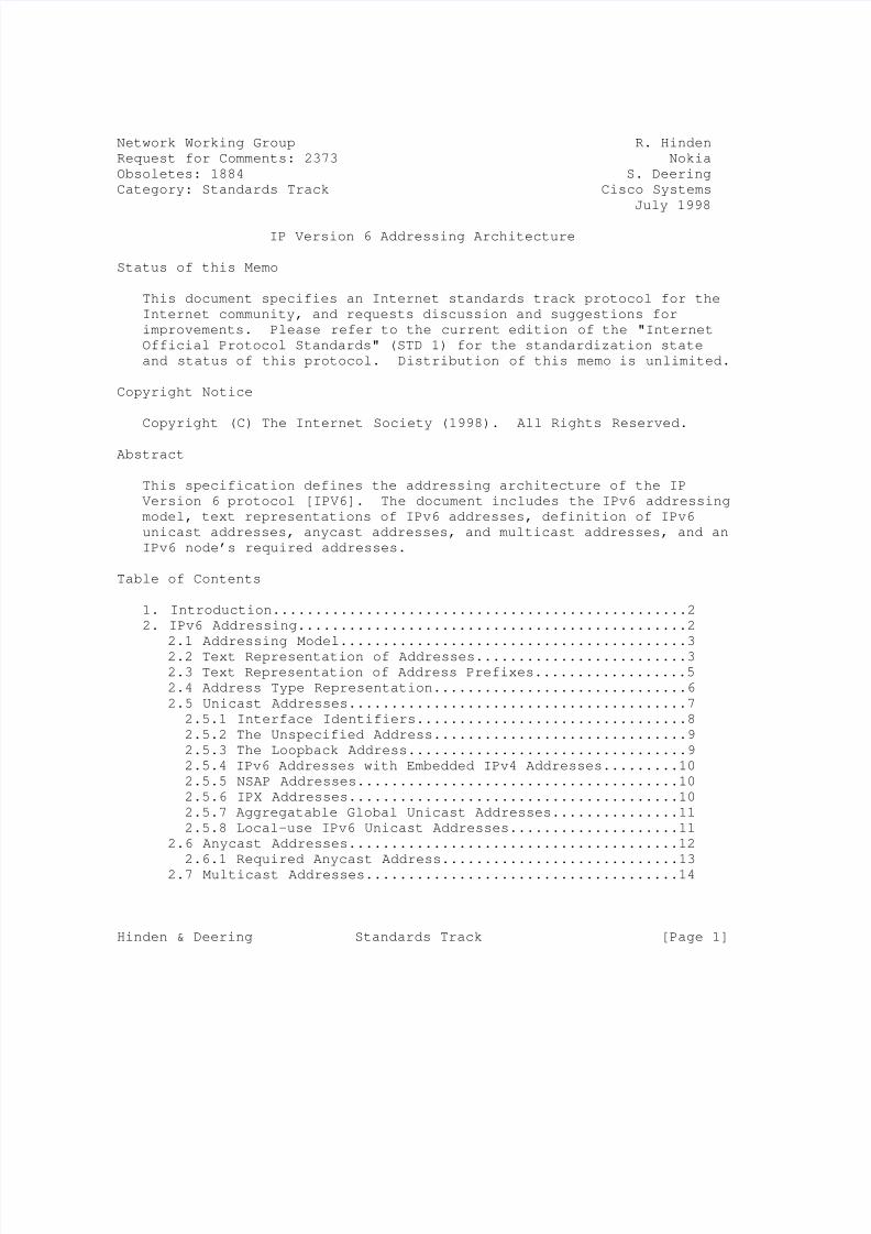
Network Working Group R. Hinden
Request for Comments: 2373 Nokia
Obsoletes: 1884 S. Deering
Category: Standards Track Cisco Systems
July 1998
IP Version 6 Addressing Architecture
Status of this Memo
This document specifies an Internet standards track protocol for the
Internet community, and requests discussion and suggestions for
improvements. Please refer to the current edition of the "Internet
Official Protocol Standards" (STD 1) for the standardization state
and status of this protocol. Distribution of this memo is unlimited.
Copyright Notice
Copyright (C) The Internet Society (1998). All Rights Reserved.
Abstract
This specification defines the addressing architecture of the IP
Version 6 protocol [IPV6]. The document includes the IPv6 addressing
model, text representations of IPv6 addresses, definition of IPv6
unicast addresses, anycast addresses, and multicast addresses, and an
IPv6 node’s required addresses.
Table of Contents
1. Introduction.................................................2
2. IPv6 Addressing..............................................2
2.1 Addressing Model.........................................3
2.2 Text Representation of Addresses.........................3
2.3 Text Representation of Address Prefixes..................5
2.4 Address Type Representation..............................6
2.5 Unicast Addresses........................................7
2.5.1 Interface Identifiers................................8
2.5.2 The Unspecified Address..............................9
2.5.3 The Loopback Address.................................9
2.5.4 IPv6 Addresses with Embedded IPv4 Addresses.........10
2.5.5 NSAP Addresses......................................10
2.5.6 IPX Addresses.......................................10
2.5.7 Aggregatable Global Unicast Addresses...............11
2.5.8 Local-use IPv6 Unicast Addresses....................11
2.6 Anycast Addresses.......................................12
2.6.1 Required Anycast Address............................13
2.7 Multicast Addresses.....................................14
Hinden & Deering Standards Track [Page 1]

8/3/2019 IPv6 Addressing Architecture_RFC2374
http://slidepdf.com/reader/full/ipv6-addressing-architecturerfc2374 2/26
RFC 2373 IPv6 Addressing Architecture July 1998
2.7.1 Pre-Defined Multicast Addresses.....................15
2.7.2 Assignment of New IPv6 Multicast Addresses..........17
2.8 A Node’s Required Addresses.............................17
3. Security Considerations.....................................18
APPENDIX A: Creating EUI-64 based Interface Identifiers........19
APPENDIX B: ABNF Description of Text Representations...........22
APPENDIX C: CHANGES FROM RFC-1884..............................23
REFERENCES.....................................................24AUTHORS’ ADDRESSES.............................................25
FULL COPYRIGHT STATEMENT.......................................26
1.0 INTRODUCTION
This specification defines the addressing architecture of the IP
Version 6 protocol. It includes a detailed description of the
currently defined address formats for IPv6 [IPV6].
The authors would like to acknowledge the contributions of Paul
Francis, Scott Bradner, Jim Bound, Brian Carpenter, Matt Crawford,
Deborah Estrin, Roger Fajman, Bob Fink, Peter Ford, Bob Gilligan,
Dimitry Haskin, Tom Harsch, Christian Huitema, Tony Li, Greg
Minshall, Thomas Narten, Erik Nordmark, Yakov Rekhter, Bill Simpson,
and Sue Thomson.
The key words "MUST", "MUST NOT", "REQUIRED", "SHALL", "SHALL NOT",
"SHOULD", "SHOULD NOT", "RECOMMENDED", "MAY", and "OPTIONAL" in this
document are to be interpreted as described in [RFC 2119].
2.0 IPv6 ADDRESSING
IPv6 addresses are 128-bit identifiers for interfaces and sets of
interfaces. There are three types of addresses:
Unicast: An identifier for a single interface. A packet sent to
a unicast address is delivered to the interface
identified by that address.
Anycast: An identifier for a set of interfaces (typically
belonging to different nodes). A packet sent to an
anycast address is delivered to one of the interfaces
identified by that address (the "nearest" one, according
to the routing protocols’ measure of distance).
Multicast: An identifier for a set of interfaces (typically
belonging to different nodes). A packet sent to a
multicast address is delivered to all interfaces
identified by that address.
Hinden & Deering Standards Track [Page 2]
8/3/2019 IPv6 Addressing Architecture_RFC2374
http://slidepdf.com/reader/full/ipv6-addressing-architecturerfc2374 3/26
RFC 2373 IPv6 Addressing Architecture July 1998
There are no broadcast addresses in IPv6, their function being
superseded by multicast addresses.
In this document, fields in addresses are given a specific name, for
example "subscriber". When this name is used with the term "ID" for
identifier after the name (e.g., "subscriber ID"), it refers to the
contents of the named field. When it is used with the term "prefix"
(e.g. "subscriber prefix") it refers to all of the address up to andincluding this field.
In IPv6, all zeros and all ones are legal values for any field,
unless specifically excluded. Specifically, prefixes may contain
zero-valued fields or end in zeros.
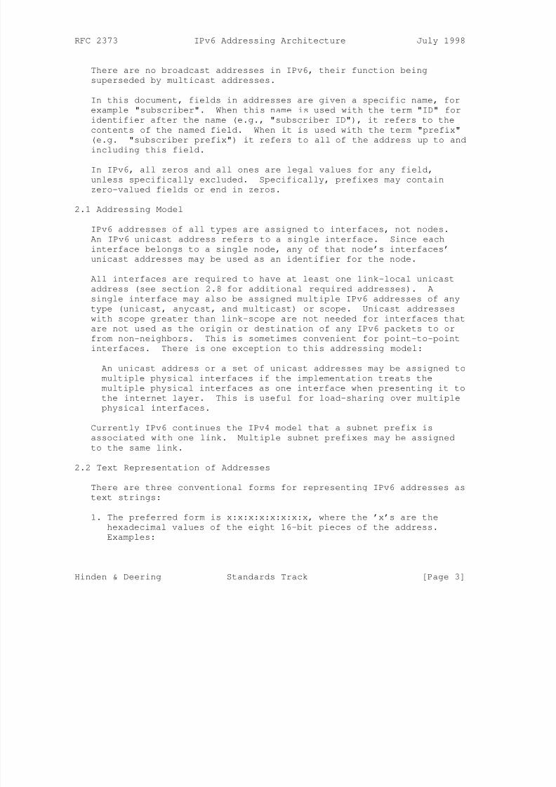
2.1 Addressing Model
IPv6 addresses of all types are assigned to interfaces, not nodes.
An IPv6 unicast address refers to a single interface. Since each
interface belongs to a single node, any of that node’s interfaces’
unicast addresses may be used as an identifier for the node.
All interfaces are required to have at least one link-local unicast
address (see section 2.8 for additional required addresses). A
single interface may also be assigned multiple IPv6 addresses of any
type (unicast, anycast, and multicast) or scope. Unicast addresses
with scope greater than link-scope are not needed for interfaces that
are not used as the origin or destination of any IPv6 packets to or
from non-neighbors. This is sometimes convenient for point-to-point
interfaces. There is one exception to this addressing model:
An unicast address or a set of unicast addresses may be assigned to
multiple physical interfaces if the implementation treats the
multiple physical interfaces as one interface when presenting it to
the internet layer. This is useful for load-sharing over multiple
physical interfaces.
Currently IPv6 continues the IPv4 model that a subnet prefix is
associated with one link. Multiple subnet prefixes may be assigned
to the same link.
2.2 Text Representation of Addresses
There are three conventional forms for representing IPv6 addresses as
text strings:
1. The preferred form is x:x:x:x:x:x:x:x, where the ’x’s are the
hexadecimal values of the eight 16-bit pieces of the address.
Examples:
Hinden & Deering Standards Track [Page 3]
8/3/2019 IPv6 Addressing Architecture_RFC2374
http://slidepdf.com/reader/full/ipv6-addressing-architecturerfc2374 4/26
RFC 2373 IPv6 Addressing Architecture July 1998
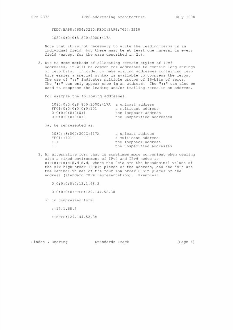
FEDC:BA98:7654:3210:FEDC:BA98:7654:3210
1080:0:0:0:8:800:200C:417A
Note that it is not necessary to write the leading zeros in an
individual field, but there must be at least one numeral in every
field (except for the case described in 2.).
2. Due to some methods of allocating certain styles of IPv6
addresses, it will be common for addresses to contain long strings
of zero bits. In order to make writing addresses containing zero
bits easier a special syntax is available to compress the zeros.
The use of "::" indicates multiple groups of 16-bits of zeros.
The "::" can only appear once in an address. The "::" can also be
used to compress the leading and/or trailing zeros in an address.
For example the following addresses:
1080:0:0:0:8:800:200C:417A a unicast address
FF01:0:0:0:0:0:0:101 a multicast address
0:0:0:0:0:0:0:1 the loopback address
0:0:0:0:0:0:0:0 the unspecified addresses
may be represented as:
1080::8:800:200C:417A a unicast address
FF01::101 a multicast address
::1 the loopback address
:: the unspecified addresses
3. An alternative form that is sometimes more convenient when dealing
with a mixed environment of IPv4 and IPv6 nodes is
x:x:x:x:x:x:d.d.d.d, where the ’x’s are the hexadecimal values of
the six high-order 16-bit pieces of the address, and the ’d’s are
the decimal values of the four low-order 8-bit pieces of the
address (standard IPv4 representation). Examples:
0:0:0:0:0:0:13.1.68.3
0:0:0:0:0:FFFF:129.144.52.38
or in compressed form:
::13.1.68.3
::FFFF:129.144.52.38
Hinden & Deering Standards Track [Page 4]
8/3/2019 IPv6 Addressing Architecture_RFC2374
http://slidepdf.com/reader/full/ipv6-addressing-architecturerfc2374 5/26
RFC 2373 IPv6 Addressing Architecture July 1998
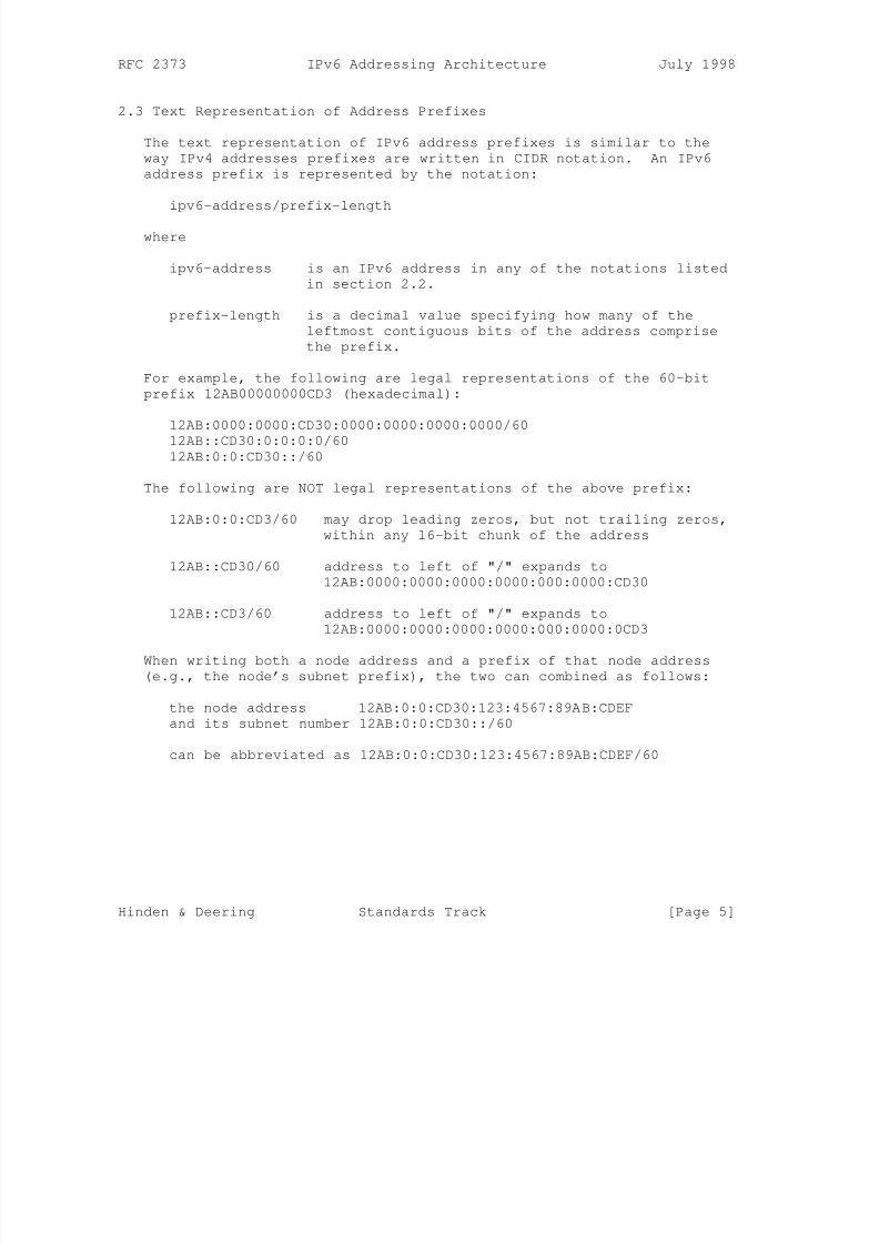
2.3 Text Representation of Address Prefixes
The text representation of IPv6 address prefixes is similar to the
way IPv4 addresses prefixes are written in CIDR notation. An IPv6
address prefix is represented by the notation:
ipv6-address/prefix-length
where
ipv6-address is an IPv6 address in any of the notations listed
in section 2.2.
prefix-length is a decimal value specifying how many of the
leftmost contiguous bits of the address comprise
the prefix.
For example, the following are legal representations of the 60-bit
prefix 12AB00000000CD3 (hexadecimal):
12AB:0000:0000:CD30:0000:0000:0000:0000/60
12AB::CD30:0:0:0:0/60
12AB:0:0:CD30::/60
The following are NOT legal representations of the above prefix:
12AB:0:0:CD3/60 may drop leading zeros, but not trailing zeros,
within any 16-bit chunk of the address
12AB::CD30/60 address to left of "/" expands to
12AB:0000:0000:0000:0000:000:0000:CD30
12AB::CD3/60 address to left of "/" expands to
12AB:0000:0000:0000:0000:000:0000:0CD3
When writing both a node address and a prefix of that node address
(e.g., the node’s subnet prefix), the two can combined as follows:
the node address 12AB:0:0:CD30:123:4567:89AB:CDEF
and its subnet number 12AB:0:0:CD30::/60
can be abbreviated as 12AB:0:0:CD30:123:4567:89AB:CDEF/60
Hinden & Deering Standards Track [Page 5]
8/3/2019 IPv6 Addressing Architecture_RFC2374
http://slidepdf.com/reader/full/ipv6-addressing-architecturerfc2374 6/26
RFC 2373 IPv6 Addressing Architecture July 1998
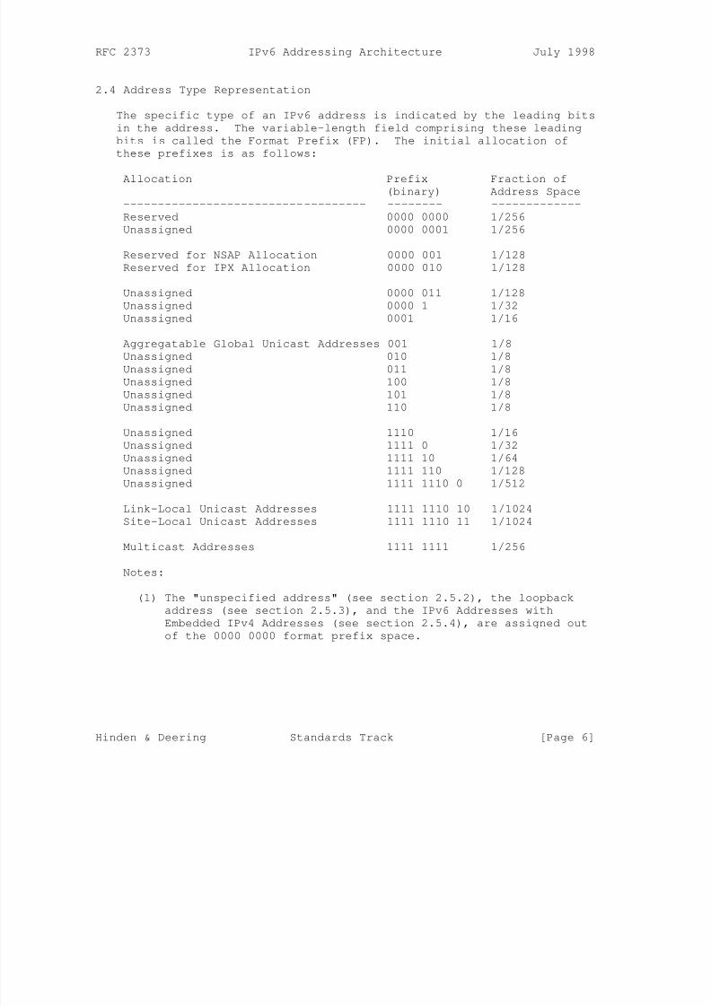
2.4 Address Type Representation
The specific type of an IPv6 address is indicated by the leading bits
in the address. The variable-length field comprising these leading
bits is called the Format Prefix (FP). The initial allocation of
these prefixes is as follows:
Allocation Prefix Fraction of(binary) Address Space
----------------------------------- -------- -------------
Reserved 0000 0000 1/256
Unassigned 0000 0001 1/256
Reserved for NSAP Allocation 0000 001 1/128
Reserved for IPX Allocation 0000 010 1/128
Unassigned 0000 011 1/128
Unassigned 0000 1 1/32
Unassigned 0001 1/16
Aggregatable Global Unicast Addresses 001 1/8
Unassigned 010 1/8
Unassigned 011 1/8
Unassigned 100 1/8
Unassigned 101 1/8
Unassigned 110 1/8
Unassigned 1110 1/16
Unassigned 1111 0 1/32
Unassigned 1111 10 1/64
Unassigned 1111 110 1/128
Unassigned 1111 1110 0 1/512
Link-Local Unicast Addresses 1111 1110 10 1/1024
Site-Local Unicast Addresses 1111 1110 11 1/1024
Multicast Addresses 1111 1111 1/256
Notes:
(1) The "unspecified address" (see section 2.5.2), the loopback
address (see section 2.5.3), and the IPv6 Addresses with
Embedded IPv4 Addresses (see section 2.5.4), are assigned out
of the 0000 0000 format prefix space.
Hinden & Deering Standards Track [Page 6]
8/3/2019 IPv6 Addressing Architecture_RFC2374
http://slidepdf.com/reader/full/ipv6-addressing-architecturerfc2374 7/26
RFC 2373 IPv6 Addressing Architecture July 1998
(2) The format prefixes 001 through 111, except for Multicast
Addresses (1111 1111), are all required to have to have 64-bit
interface identifiers in EUI-64 format. See section 2.5.1 for
definitions.
This allocation supports the direct allocation of aggregation
addresses, local use addresses, and multicast addresses. Space is
reserved for NSAP addresses and IPX addresses. The remainder of theaddress space is unassigned for future use. This can be used for
expansion of existing use (e.g., additional aggregatable addresses,
etc.) or new uses (e.g., separate locators and identifiers). Fifteen
percent of the address space is initially allocated. The remaining
85% is reserved for future use.
Unicast addresses are distinguished from multicast addresses by the
value of the high-order octet of the addresses: a value of FF
(11111111) identifies an address as a multicast address; any other
value identifies an address as a unicast address. Anycast addresses
are taken from the unicast address space, and are not syntactically
distinguishable from unicast addresses.
2.5 Unicast Addresses
IPv6 unicast addresses are aggregatable with contiguous bit-wise
masks similar to IPv4 addresses under Class-less Interdomain Routing
[CIDR].
There are several forms of unicast address assignment in IPv6,
including the global aggregatable global unicast address, the NSAP
address, the IPX hierarchical address, the site-local address, the
link-local address, and the IPv4-capable host address. Additional
address types can be defined in the future.
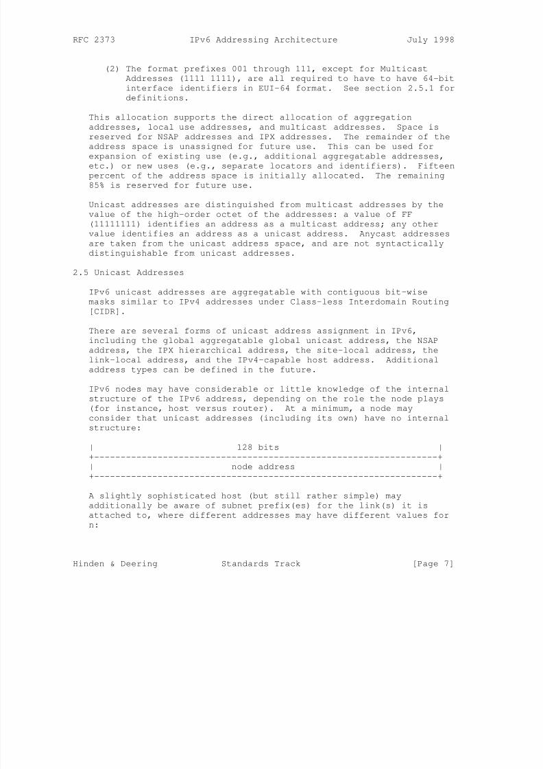
IPv6 nodes may have considerable or little knowledge of the internal
structure of the IPv6 address, depending on the role the node plays
(for instance, host versus router). At a minimum, a node may
consider that unicast addresses (including its own) have no internal
structure:
| 128 bits |
+-----------------------------------------------------------------+
| node address |
+-----------------------------------------------------------------+
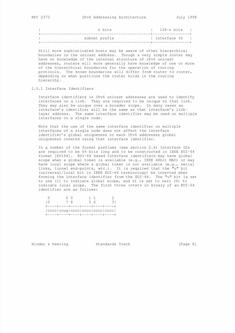
A slightly sophisticated host (but still rather simple) may
additionally be aware of subnet prefix(es) for the link(s) it is
attached to, where different addresses may have different values for
n:
Hinden & Deering Standards Track [Page 7]
8/3/2019 IPv6 Addressing Architecture_RFC2374
http://slidepdf.com/reader/full/ipv6-addressing-architecturerfc2374 8/26
RFC 2373 IPv6 Addressing Architecture July 1998
| n bits | 128-n bits |
+------------------------------------------------+----------------+
| subnet prefix | interface ID |
+------------------------------------------------+----------------+
Still more sophisticated hosts may be aware of other hierarchical
boundaries in the unicast address. Though a very simple router may
have no knowledge of the internal structure of IPv6 unicastaddresses, routers will more generally have knowledge of one or more
of the hierarchical boundaries for the operation of routing
protocols. The known boundaries will differ from router to router,
depending on what positions the router holds in the routing
hierarchy.
2.5.1 Interface Identifiers
Interface identifiers in IPv6 unicast addresses are used to identify
interfaces on a link. They are required to be unique on that link.
They may also be unique over a broader scope. In many cases an
interface’s identifier will be the same as that interface’s link-
layer address. The same interface identifier may be used on multiple
interfaces on a single node.
Note that the use of the same interface identifier on multiple
interfaces of a single node does not affect the interface
identifier’s global uniqueness or each IPv6 addresses global
uniqueness created using that interface identifier.
In a number of the format prefixes (see section 2.4) Interface IDs
are required to be 64 bits long and to be constructed in IEEE EUI-64
format [EUI64]. EUI-64 based Interface identifiers may have global
scope when a global token is available (e.g., IEEE 48bit MAC) or may
have local scope where a global token is not available (e.g., serial
links, tunnel end-points, etc.). It is required that the "u" bit
(universal/local bit in IEEE EUI-64 terminology) be inverted when
forming the interface identifier from the EUI-64. The "u" bit is set
to one (1) to indicate global scope, and it is set to zero (0) to
indicate local scope. The first three octets in binary of an EUI-64
identifier are as follows:
0 0 0 1 1 2
|0 7 8 5 6 3|
+----+----+----+----+----+----+
|cccc|ccug|cccc|cccc|cccc|cccc|
+----+----+----+----+----+----+
Hinden & Deering Standards Track [Page 8]
8/3/2019 IPv6 Addressing Architecture_RFC2374
http://slidepdf.com/reader/full/ipv6-addressing-architecturerfc2374 9/26
RFC 2373 IPv6 Addressing Architecture July 1998
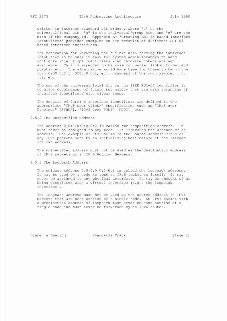
written in Internet standard bit-order , where "u" is the
universal/local bit, "g" is the individual/group bit, and "c" are the
bits of the company_id. Appendix A: "Creating EUI-64 based Interface
Identifiers" provides examples on the creation of different EUI-64
based interface identifiers.
The motivation for inverting the "u" bit when forming the interface
identifier is to make it easy for system administrators to handconfigure local scope identifiers when hardware tokens are not
available. This is expected to be case for serial links, tunnel end-
points, etc. The alternative would have been for these to be of the
form 0200:0:0:1, 0200:0:0:2, etc., instead of the much simpler ::1,
::2, etc.
The use of the universal/local bit in the IEEE EUI-64 identifier is
to allow development of future technology that can take advantage of
interface identifiers with global scope.
The details of forming interface identifiers are defined in the
appropriate "IPv6 over <link>" specification such as "IPv6 over
Ethernet" [ETHER], "IPv6 over FDDI" [FDDI], etc.
2.5.2 The Unspecified Address
The address 0:0:0:0:0:0:0:0 is called the unspecified address. It
must never be assigned to any node. It indicates the absence of an
address. One example of its use is in the Source Address field of
any IPv6 packets sent by an initializing host before it has learned
its own address.
The unspecified address must not be used as the destination address
of IPv6 packets or in IPv6 Routing Headers.
2.5.3 The Loopback Address
The unicast address 0:0:0:0:0:0:0:1 is called the loopback address.
It may be used by a node to send an IPv6 packet to itself. It may
never be assigned to any physical interface. It may be thought of as
being associated with a virtual interface (e.g., the loopback
interface).
The loopback address must not be used as the source address in IPv6
packets that are sent outside of a single node. An IPv6 packet with
a destination address of loopback must never be sent outside of a
single node and must never be forwarded by an IPv6 router.
Hinden & Deering Standards Track [Page 9]
8/3/2019 IPv6 Addressing Architecture_RFC2374
http://slidepdf.com/reader/full/ipv6-addressing-architecturerfc2374 10/26
RFC 2373 IPv6 Addressing Architecture July 1998
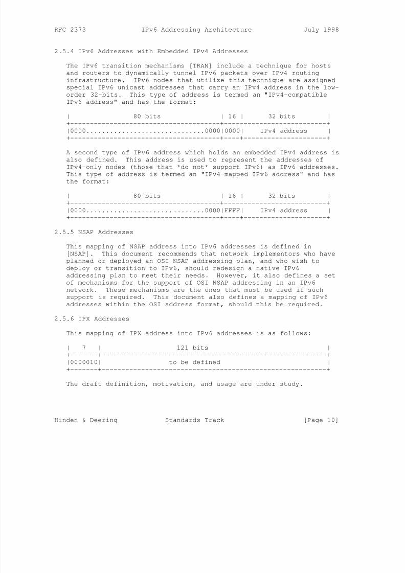
2.5.4 IPv6 Addresses with Embedded IPv4 Addresses
The IPv6 transition mechanisms [TRAN] include a technique for hosts
and routers to dynamically tunnel IPv6 packets over IPv4 routing
infrastructure. IPv6 nodes that utilize this technique are assigned
special IPv6 unicast addresses that carry an IPv4 address in the low-
order 32-bits. This type of address is termed an "IPv4-compatible
IPv6 address" and has the format:
| 80 bits | 16 | 32 bits |
+--------------------------------------+--------------------------+
|0000..............................0000|0000| IPv4 address |
+--------------------------------------+----+---------------------+
A second type of IPv6 address which holds an embedded IPv4 address is
also defined. This address is used to represent the addresses of
IPv4-only nodes (those that *do not* support IPv6) as IPv6 addresses.
This type of address is termed an "IPv4-mapped IPv6 address" and has
the format:
| 80 bits | 16 | 32 bits |
+--------------------------------------+--------------------------+
|0000..............................0000|FFFF| IPv4 address |
+--------------------------------------+----+---------------------+
2.5.5 NSAP Addresses
This mapping of NSAP address into IPv6 addresses is defined in
[NSAP]. This document recommends that network implementors who have
planned or deployed an OSI NSAP addressing plan, and who wish to
deploy or transition to IPv6, should redesign a native IPv6
addressing plan to meet their needs. However, it also defines a set
of mechanisms for the support of OSI NSAP addressing in an IPv6
network. These mechanisms are the ones that must be used if such
support is required. This document also defines a mapping of IPv6
addresses within the OSI address format, should this be required.
2.5.6 IPX Addresses
This mapping of IPX address into IPv6 addresses is as follows:
| 7 | 121 bits |
+-------+---------------------------------------------------------+
|0000010| to be defined |
+-------+---------------------------------------------------------+
The draft definition, motivation, and usage are under study.
Hinden & Deering Standards Track [Page 10]
8/3/2019 IPv6 Addressing Architecture_RFC2374
http://slidepdf.com/reader/full/ipv6-addressing-architecturerfc2374 11/26
RFC 2373 IPv6 Addressing Architecture July 1998
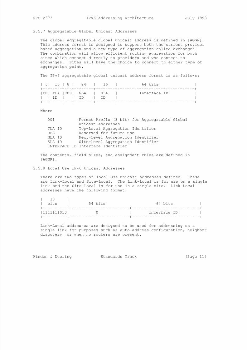
2.5.7 Aggregatable Global Unicast Addresses
The global aggregatable global unicast address is defined in [AGGR].
This address format is designed to support both the current provider
based aggregation and a new type of aggregation called exchanges.
The combination will allow efficient routing aggregation for both
sites which connect directly to providers and who connect to
exchanges. Sites will have the choice to connect to either type ofaggregation point.
The IPv6 aggregatable global unicast address format is as follows:
| 3| 13 | 8 | 24 | 16 | 64 bits |
+--+-----+---+--------+--------+--------------------------------+
|FP| TLA |RES| NLA | SLA | Interface ID |
| | ID | | ID | ID | |
+--+-----+---+--------+--------+--------------------------------+
Where
001 Format Prefix (3 bit) for Aggregatable Global
Unicast Addresses
TLA ID Top-Level Aggregation Identifier
RES Reserved for future use
NLA ID Next-Level Aggregation Identifier
SLA ID Site-Level Aggregation Identifier
INTERFACE ID Interface Identifier
The contents, field sizes, and assignment rules are defined in
[AGGR].
2.5.8 Local-Use IPv6 Unicast Addresses
There are two types of local-use unicast addresses defined. These
are Link-Local and Site-Local. The Link-Local is for use on a single
link and the Site-Local is for use in a single site. Link-Local
addresses have the following format:
| 10 |
| bits | 54 bits | 64 bits |
+----------+-------------------------+----------------------------+
|1111111010| 0 | interface ID |
+----------+-------------------------+----------------------------+
Link-Local addresses are designed to be used for addressing on a
single link for purposes such as auto-address configuration, neighbor
discovery, or when no routers are present.
Hinden & Deering Standards Track [Page 11]
8/3/2019 IPv6 Addressing Architecture_RFC2374
http://slidepdf.com/reader/full/ipv6-addressing-architecturerfc2374 12/26
RFC 2373 IPv6 Addressing Architecture July 1998
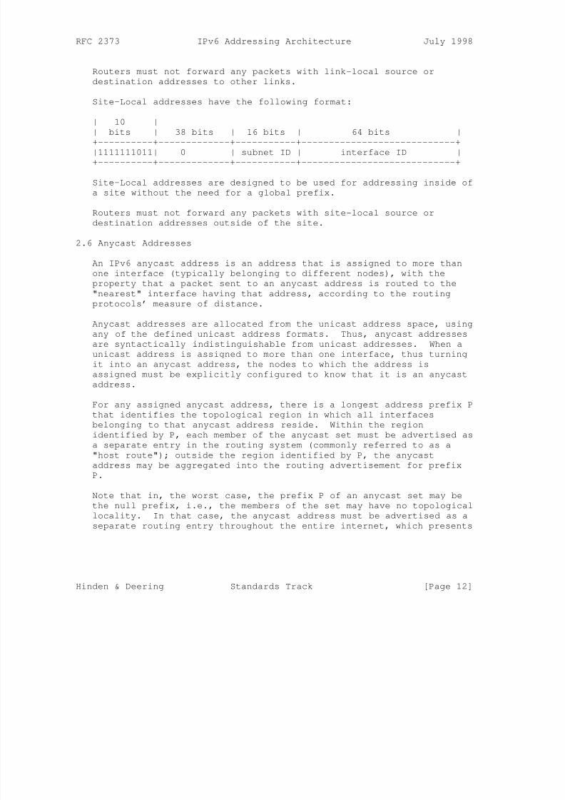
Routers must not forward any packets with link-local source or
destination addresses to other links.
Site-Local addresses have the following format:
| 10 |
| bits | 38 bits | 16 bits | 64 bits |
+----------+-------------+-----------+----------------------------+|1111111011| 0 | subnet ID | interface ID |
+----------+-------------+-----------+----------------------------+
Site-Local addresses are designed to be used for addressing inside of
a site without the need for a global prefix.
Routers must not forward any packets with site-local source or
destination addresses outside of the site.
2.6 Anycast Addresses
An IPv6 anycast address is an address that is assigned to more than
one interface (typically belonging to different nodes), with the
property that a packet sent to an anycast address is routed to the
"nearest" interface having that address, according to the routing
protocols’ measure of distance.
Anycast addresses are allocated from the unicast address space, using
any of the defined unicast address formats. Thus, anycast addresses
are syntactically indistinguishable from unicast addresses. When a
unicast address is assigned to more than one interface, thus turning
it into an anycast address, the nodes to which the address is
assigned must be explicitly configured to know that it is an anycast
address.
For any assigned anycast address, there is a longest address prefix P
that identifies the topological region in which all interfaces
belonging to that anycast address reside. Within the region
identified by P, each member of the anycast set must be advertised as
a separate entry in the routing system (commonly referred to as a
"host route"); outside the region identified by P, the anycast
address may be aggregated into the routing advertisement for prefix
P.
Note that in, the worst case, the prefix P of an anycast set may be
the null prefix, i.e., the members of the set may have no topological
locality. In that case, the anycast address must be advertised as a
separate routing entry throughout the entire internet, which presents
Hinden & Deering Standards Track [Page 12]
8/3/2019 IPv6 Addressing Architecture_RFC2374
http://slidepdf.com/reader/full/ipv6-addressing-architecturerfc2374 13/26
RFC 2373 IPv6 Addressing Architecture July 1998
a severe scaling limit on how many such "global" anycast sets may be
supported. Therefore, it is expected that support for global anycast
sets may be unavailable or very restricted.
One expected use of anycast addresses is to identify the set of
routers belonging to an organization providing internet service.
Such addresses could be used as intermediate addresses in an IPv6
Routing header, to cause a packet to be delivered via a particularaggregation or sequence of aggregations. Some other possible uses
are to identify the set of routers attached to a particular subnet,
or the set of routers providing entry into a particular routing
domain.
There is little experience with widespread, arbitrary use of internet
anycast addresses, and some known complications and hazards when
using them in their full generality [ANYCST]. Until more experience
has been gained and solutions agreed upon for those problems, the
following restrictions are imposed on IPv6 anycast addresses:
o An anycast address must not be used as the source address of an
IPv6 packet.
o An anycast address must not be assigned to an IPv6 host, that
is, it may be assigned to an IPv6 router only.
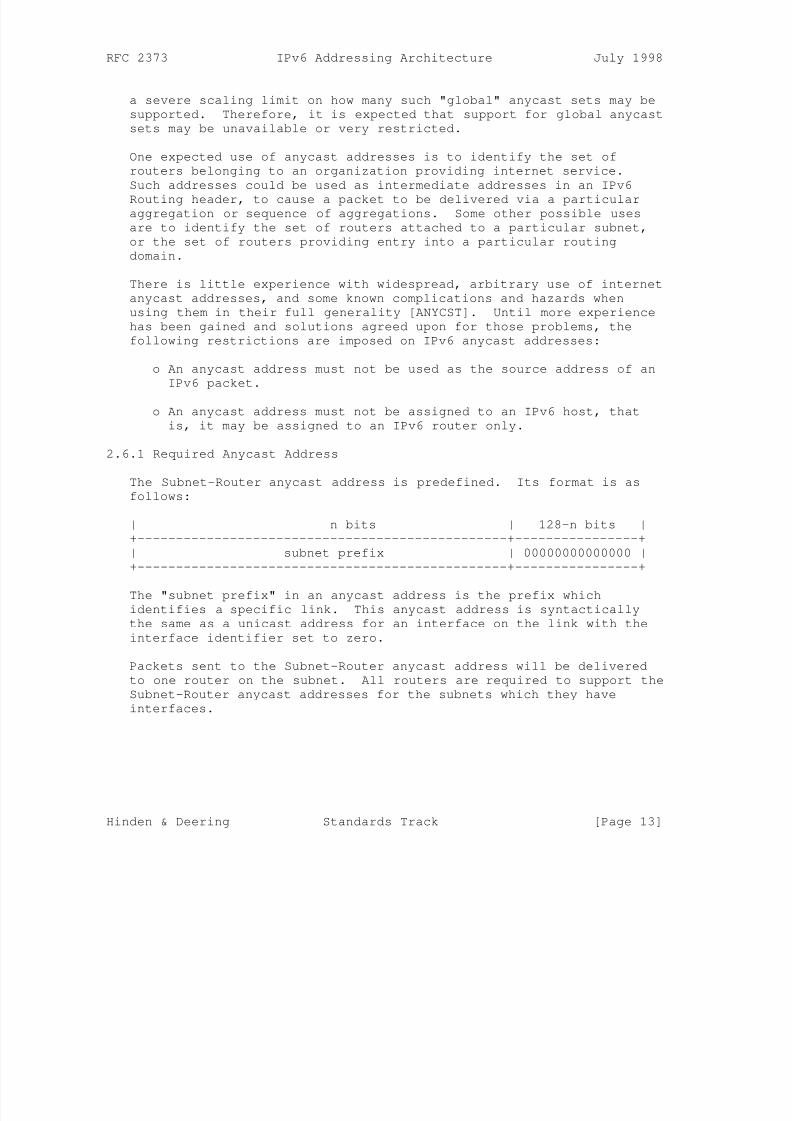
2.6.1 Required Anycast Address
The Subnet-Router anycast address is predefined. Its format is as
follows:
| n bits | 128-n bits |
+------------------------------------------------+----------------+
| subnet prefix | 00000000000000 |
+------------------------------------------------+----------------+
The "subnet prefix" in an anycast address is the prefix which
identifies a specific link. This anycast address is syntactically
the same as a unicast address for an interface on the link with the
interface identifier set to zero.
Packets sent to the Subnet-Router anycast address will be delivered
to one router on the subnet. All routers are required to support the
Subnet-Router anycast addresses for the subnets which they have
interfaces.
Hinden & Deering Standards Track [Page 13]
8/3/2019 IPv6 Addressing Architecture_RFC2374
http://slidepdf.com/reader/full/ipv6-addressing-architecturerfc2374 14/26
RFC 2373 IPv6 Addressing Architecture July 1998
The subnet-router anycast address is intended to be used for
applications where a node needs to communicate with one of a set of
routers on a remote subnet. For example when a mobile host needs to
communicate with one of the mobile agents on its "home" subnet.
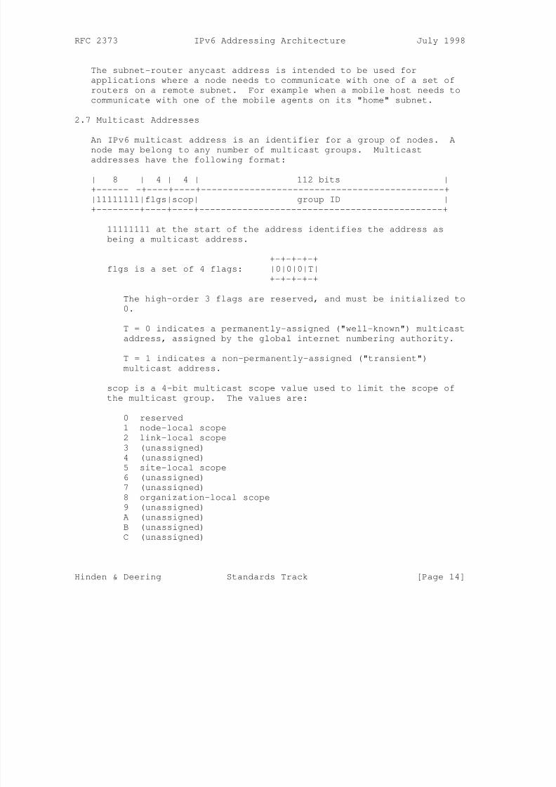
2.7 Multicast Addresses
An IPv6 multicast address is an identifier for a group of nodes. Anode may belong to any number of multicast groups. Multicast
addresses have the following format:
| 8 | 4 | 4 | 112 bits |
+------ -+----+----+---------------------------------------------+
|11111111|flgs|scop| group ID |
+--------+----+----+---------------------------------------------+
11111111 at the start of the address identifies the address as
being a multicast address.
+-+-+-+-+
flgs is a set of 4 flags: |0|0|0|T|
+-+-+-+-+
The high-order 3 flags are reserved, and must be initialized to
0.
T = 0 indicates a permanently-assigned ("well-known") multicast
address, assigned by the global internet numbering authority.
T = 1 indicates a non-permanently-assigned ("transient")
multicast address.
scop is a 4-bit multicast scope value used to limit the scope of
the multicast group. The values are:
0 reserved
1 node-local scope
2 link-local scope
3 (unassigned)
4 (unassigned)
5 site-local scope
6 (unassigned)
7 (unassigned)
8 organization-local scope
9 (unassigned)
A (unassigned)
B (unassigned)
C (unassigned)
Hinden & Deering Standards Track [Page 14]
8/3/2019 IPv6 Addressing Architecture_RFC2374
http://slidepdf.com/reader/full/ipv6-addressing-architecturerfc2374 15/26
RFC 2373 IPv6 Addressing Architecture July 1998
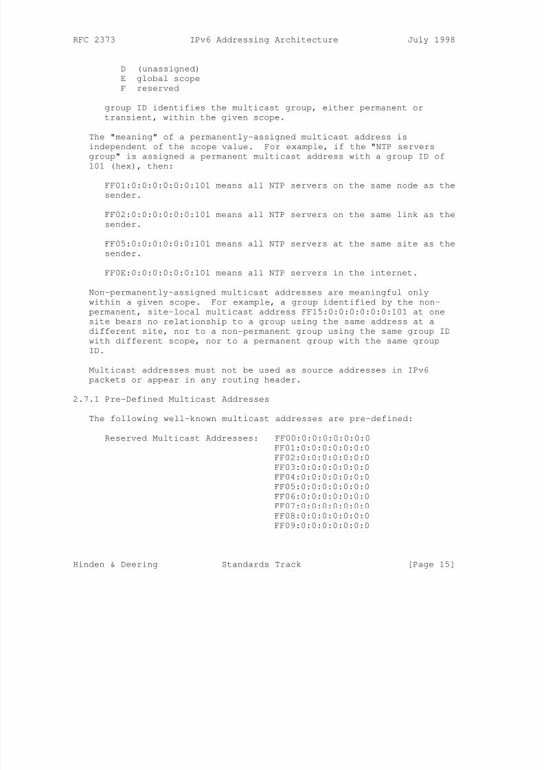
D (unassigned)
E global scope
F reserved
group ID identifies the multicast group, either permanent or
transient, within the given scope.
The "meaning" of a permanently-assigned multicast address isindependent of the scope value. For example, if the "NTP servers
group" is assigned a permanent multicast address with a group ID of
101 (hex), then:
FF01:0:0:0:0:0:0:101 means all NTP servers on the same node as the
sender.
FF02:0:0:0:0:0:0:101 means all NTP servers on the same link as the
sender.
FF05:0:0:0:0:0:0:101 means all NTP servers at the same site as the
sender.
FF0E:0:0:0:0:0:0:101 means all NTP servers in the internet.
Non-permanently-assigned multicast addresses are meaningful only
within a given scope. For example, a group identified by the non-
permanent, site-local multicast address FF15:0:0:0:0:0:0:101 at one
site bears no relationship to a group using the same address at a
different site, nor to a non-permanent group using the same group ID
with different scope, nor to a permanent group with the same group
ID.
Multicast addresses must not be used as source addresses in IPv6
packets or appear in any routing header.
2.7.1 Pre-Defined Multicast Addresses
The following well-known multicast addresses are pre-defined:
Reserved Multicast Addresses: FF00:0:0:0:0:0:0:0
FF01:0:0:0:0:0:0:0
FF02:0:0:0:0:0:0:0
FF03:0:0:0:0:0:0:0
FF04:0:0:0:0:0:0:0
FF05:0:0:0:0:0:0:0
FF06:0:0:0:0:0:0:0
FF07:0:0:0:0:0:0:0
FF08:0:0:0:0:0:0:0
FF09:0:0:0:0:0:0:0
Hinden & Deering Standards Track [Page 15]
8/3/2019 IPv6 Addressing Architecture_RFC2374
http://slidepdf.com/reader/full/ipv6-addressing-architecturerfc2374 16/26
RFC 2373 IPv6 Addressing Architecture July 1998
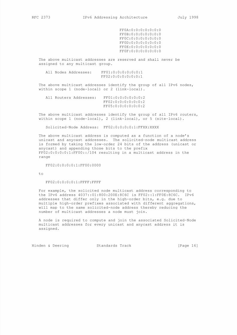
FF0A:0:0:0:0:0:0:0
FF0B:0:0:0:0:0:0:0
FF0C:0:0:0:0:0:0:0
FF0D:0:0:0:0:0:0:0
FF0E:0:0:0:0:0:0:0
FF0F:0:0:0:0:0:0:0
The above multicast addresses are reserved and shall never beassigned to any multicast group.
All Nodes Addresses: FF01:0:0:0:0:0:0:1
FF02:0:0:0:0:0:0:1
The above multicast addresses identify the group of all IPv6 nodes,
within scope 1 (node-local) or 2 (link-local).
All Routers Addresses: FF01:0:0:0:0:0:0:2
FF02:0:0:0:0:0:0:2
FF05:0:0:0:0:0:0:2
The above multicast addresses identify the group of all IPv6 routers,
within scope 1 (node-local), 2 (link-local), or 5 (site-local).
Solicited-Node Address: FF02:0:0:0:0:1:FFXX:XXXX
The above multicast address is computed as a function of a node’s
unicast and anycast addresses. The solicited-node multicast address
is formed by taking the low-order 24 bits of the address (unicast or
anycast) and appending those bits to the prefix
FF02:0:0:0:0:1:FF00::/104 resulting in a multicast address in the
range
FF02:0:0:0:0:1:FF00:0000
to
FF02:0:0:0:0:1:FFFF:FFFF
For example, the solicited node multicast address corresponding to
the IPv6 address 4037::01:800:200E:8C6C is FF02::1:FF0E:8C6C. IPv6
addresses that differ only in the high-order bits, e.g. due to
multiple high-order prefixes associated with different aggregations,
will map to the same solicited-node address thereby reducing the
number of multicast addresses a node must join.
A node is required to compute and join the associated Solicited-Node
multicast addresses for every unicast and anycast address it is
assigned.
Hinden & Deering Standards Track [Page 16]
8/3/2019 IPv6 Addressing Architecture_RFC2374
http://slidepdf.com/reader/full/ipv6-addressing-architecturerfc2374 17/26
RFC 2373 IPv6 Addressing Architecture July 1998
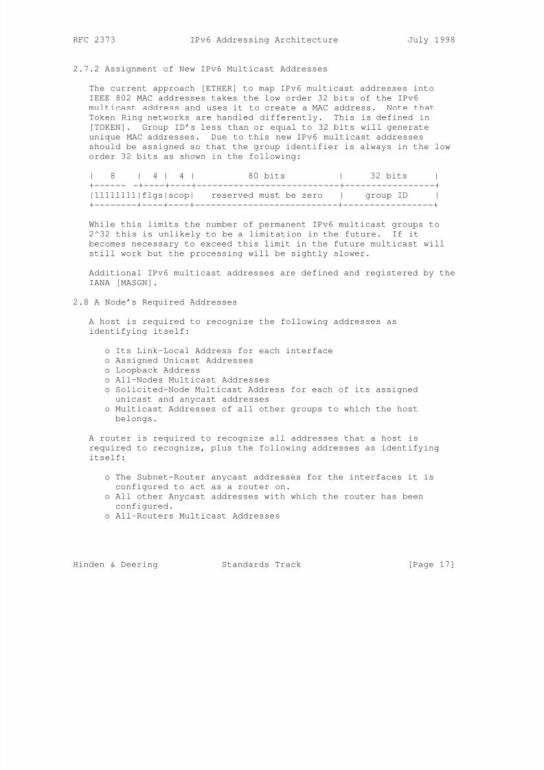
2.7.2 Assignment of New IPv6 Multicast Addresses
The current approach [ETHER] to map IPv6 multicast addresses into
IEEE 802 MAC addresses takes the low order 32 bits of the IPv6
multicast address and uses it to create a MAC address. Note that
Token Ring networks are handled differently. This is defined in
[TOKEN]. Group ID’s less than or equal to 32 bits will generate
unique MAC addresses. Due to this new IPv6 multicast addressesshould be assigned so that the group identifier is always in the low
order 32 bits as shown in the following:
| 8 | 4 | 4 | 80 bits | 32 bits |
+------ -+----+----+---------------------------+-----------------+
|11111111|flgs|scop| reserved must be zero | group ID |
+--------+----+----+---------------------------+-----------------+
While this limits the number of permanent IPv6 multicast groups to
2^32 this is unlikely to be a limitation in the future. If it
becomes necessary to exceed this limit in the future multicast will
still work but the processing will be sightly slower.
Additional IPv6 multicast addresses are defined and registered by the
IANA [MASGN].
2.8 A Node’s Required Addresses
A host is required to recognize the following addresses as
identifying itself:
o Its Link-Local Address for each interface
o Assigned Unicast Addresses
o Loopback Address
o All-Nodes Multicast Addresses
o Solicited-Node Multicast Address for each of its assigned
unicast and anycast addresses
o Multicast Addresses of all other groups to which the host
belongs.
A router is required to recognize all addresses that a host is
required to recognize, plus the following addresses as identifying
itself:
o The Subnet-Router anycast addresses for the interfaces it is
configured to act as a router on.
o All other Anycast addresses with which the router has been
configured.
o All-Routers Multicast Addresses
Hinden & Deering Standards Track [Page 17]

8/3/2019 IPv6 Addressing Architecture_RFC2374
http://slidepdf.com/reader/full/ipv6-addressing-architecturerfc2374 18/26
RFC 2373 IPv6 Addressing Architecture July 1998
o Multicast Addresses of all other groups to which the router
belongs.
The only address prefixes which should be predefined in an
implementation are the:
o Unspecified Address
o Loopback Addresso Multicast Prefix (FF)
o Local-Use Prefixes (Link-Local and Site-Local)
o Pre-Defined Multicast Addresses
o IPv4-Compatible Prefixes
Implementations should assume all other addresses are unicast unless
specifically configured (e.g., anycast addresses).
3. Security Considerations
IPv6 addressing documents do not have any direct impact on Internet
infrastructure security. Authentication of IPv6 packets is defined
in [AUTH].
Hinden & Deering Standards Track [Page 18]
8/3/2019 IPv6 Addressing Architecture_RFC2374
http://slidepdf.com/reader/full/ipv6-addressing-architecturerfc2374 19/26
RFC 2373 IPv6 Addressing Architecture July 1998
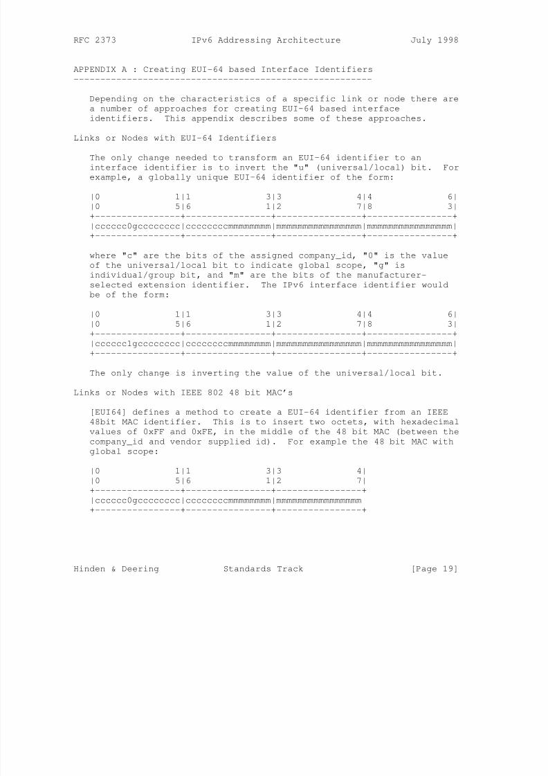
APPENDIX A : Creating EUI-64 based Interface Identifiers
--------------------------------------------------------
Depending on the characteristics of a specific link or node there are
a number of approaches for creating EUI-64 based interface
identifiers. This appendix describes some of these approaches.
Links or Nodes with EUI-64 Identifiers
The only change needed to transform an EUI-64 identifier to an
interface identifier is to invert the "u" (universal/local) bit. For
example, a globally unique EUI-64 identifier of the form:
|0 1|1 3|3 4|4 6|
|0 5|6 1|2 7|8 3|
+----------------+----------------+----------------+----------------+
|cccccc0gcccccccc|ccccccccmmmmmmmm|mmmmmmmmmmmmmmmm|mmmmmmmmmmmmmmmm|
+----------------+----------------+----------------+----------------+
where "c" are the bits of the assigned company_id, "0" is the value
of the universal/local bit to indicate global scope, "g" is
individual/group bit, and "m" are the bits of the manufacturer-
selected extension identifier. The IPv6 interface identifier would
be of the form:
|0 1|1 3|3 4|4 6|
|0 5|6 1|2 7|8 3|
+----------------+----------------+----------------+----------------+
|cccccc1gcccccccc|ccccccccmmmmmmmm|mmmmmmmmmmmmmmmm|mmmmmmmmmmmmmmmm|
+----------------+----------------+----------------+----------------+
The only change is inverting the value of the universal/local bit.
Links or Nodes with IEEE 802 48 bit MAC’s
[EUI64] defines a method to create a EUI-64 identifier from an IEEE
48bit MAC identifier. This is to insert two octets, with hexadecimal
values of 0xFF and 0xFE, in the middle of the 48 bit MAC (between the
company_id and vendor supplied id). For example the 48 bit MAC with
global scope:
|0 1|1 3|3 4|
|0 5|6 1|2 7|
+----------------+----------------+----------------+
|cccccc0gcccccccc|ccccccccmmmmmmmm|mmmmmmmmmmmmmmmm|
+----------------+----------------+----------------+
Hinden & Deering Standards Track [Page 19]
8/3/2019 IPv6 Addressing Architecture_RFC2374
http://slidepdf.com/reader/full/ipv6-addressing-architecturerfc2374 20/26
RFC 2373 IPv6 Addressing Architecture July 1998
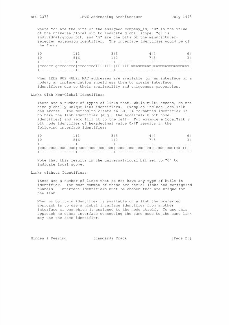
where "c" are the bits of the assigned company_id, "0" is the value
of the universal/local bit to indicate global scope, "g" is
individual/group bit, and "m" are the bits of the manufacturer-
selected extension identifier. The interface identifier would be of
the form:
|0 1|1 3|3 4|4 6|
|0 5|6 1|2 7|8 3|+----------------+----------------+----------------+----------------+
|cccccc1gcccccccc|cccccccc11111111|11111110mmmmmmmm|mmmmmmmmmmmmmmmm|
+----------------+----------------+----------------+----------------+
When IEEE 802 48bit MAC addresses are available (on an interface or a
node), an implementation should use them to create interface
identifiers due to their availability and uniqueness properties.
Links with Non-Global Identifiers
There are a number of types of links that, while multi-access, do not
have globally unique link identifiers. Examples include LocalTalk
and Arcnet. The method to create an EUI-64 formatted identifier is
to take the link identifier (e.g., the LocalTalk 8 bit node
identifier) and zero fill it to the left. For example a LocalTalk 8
bit node identifier of hexadecimal value 0x4F results in the
following interface identifier:
|0 1|1 3|3 4|4 6|
|0 5|6 1|2 7|8 3|
+----------------+----------------+----------------+----------------+
|0000000000000000|0000000000000000|0000000000000000|0000000001001111|
+----------------+----------------+----------------+----------------+
Note that this results in the universal/local bit set to "0" to
indicate local scope.
Links without Identifiers
There are a number of links that do not have any type of built-in
identifier. The most common of these are serial links and configured
tunnels. Interface identifiers must be chosen that are unique for
the link.
When no built-in identifier is available on a link the preferred
approach is to use a global interface identifier from another
interface or one which is assigned to the node itself. To use this
approach no other interface connecting the same node to the same link
may use the same identifier.
Hinden & Deering Standards Track [Page 20]
8/3/2019 IPv6 Addressing Architecture_RFC2374
http://slidepdf.com/reader/full/ipv6-addressing-architecturerfc2374 21/26
RFC 2373 IPv6 Addressing Architecture July 1998
If there is no global interface identifier available for use on the
link the implementation needs to create a local scope interface
identifier. The only requirement is that it be unique on the link.
There are many possible approaches to select a link-unique interface
identifier. They include:
Manual Configuration
Generated Random NumberNode Serial Number (or other node-specific token)
The link-unique interface identifier should be generated in a manner
that it does not change after a reboot of a node or if interfaces are
added or deleted from the node.
The selection of the appropriate algorithm is link and implementation
dependent. The details on forming interface identifiers are defined
in the appropriate "IPv6 over <link>" specification. It is strongly
recommended that a collision detection algorithm be implemented as
part of any automatic algorithm.
Hinden & Deering Standards Track [Page 21]
8/3/2019 IPv6 Addressing Architecture_RFC2374
http://slidepdf.com/reader/full/ipv6-addressing-architecturerfc2374 22/26
RFC 2373 IPv6 Addressing Architecture July 1998
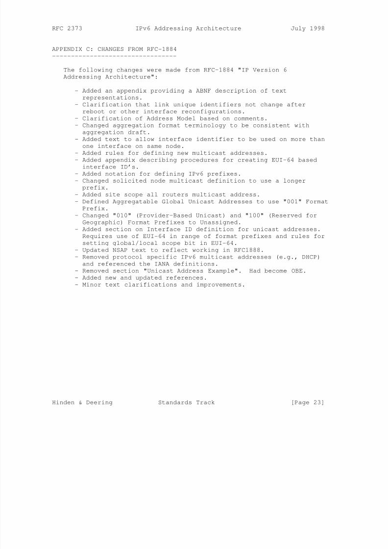
APPENDIX B: ABNF Description of Text Representations
----------------------------------------------------
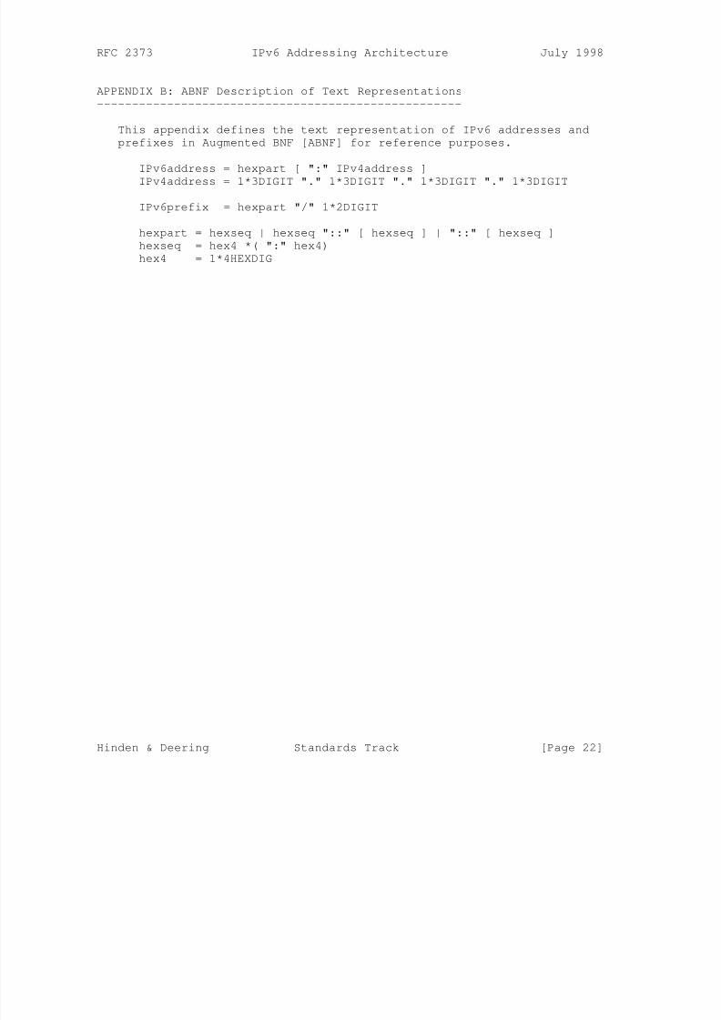
This appendix defines the text representation of IPv6 addresses and
prefixes in Augmented BNF [ABNF] for reference purposes.
IPv6address = hexpart [ ":" IPv4address ]
IPv4address = 1*3DIGIT "." 1*3DIGIT "." 1*3DIGIT "." 1*3DIGIT
IPv6prefix = hexpart "/" 1*2DIGIT
hexpart = hexseq | hexseq "::" [ hexseq ] | "::" [ hexseq ]
hexseq = hex4 *( ":" hex4)
hex4 = 1*4HEXDIG
Hinden & Deering Standards Track [Page 22]
8/3/2019 IPv6 Addressing Architecture_RFC2374
http://slidepdf.com/reader/full/ipv6-addressing-architecturerfc2374 23/26

8/3/2019 IPv6 Addressing Architecture_RFC2374
http://slidepdf.com/reader/full/ipv6-addressing-architecturerfc2374 24/26
RFC 2373 IPv6 Addressing Architecture July 1998
REFERENCES
[ABNF] Crocker, D., and P. Overell, "Augmented BNF for
Syntax Specifications: ABNF", RFC 2234, November 1997.
[AGGR] Hinden, R., O’Dell, M., and S. Deering, "An
Aggregatable Global Unicast Address Format", RFC 2374, July
1998.
[AUTH] Atkinson, R., "IP Authentication Header", RFC 1826, August
1995.
[ANYCST] Partridge, C., Mendez, T., and W. Milliken, "Host
Anycasting Service", RFC 1546, November 1993.
[CIDR] Fuller, V., Li, T., Yu, J., and K. Varadhan, "Classless
Inter-Domain Routing (CIDR): An Address Assignment and
Aggregation Strategy", RFC 1519, September 1993.
[ETHER] Crawford, M., "Transmission of IPv6 Pacekts over Ethernet
Networks", Work in Progress.
[EUI64] IEEE, "Guidelines for 64-bit Global Identifier (EUI-64)
Registration Authority",
http://standards.ieee.org/db/oui/tutorials/EUI64.html,
March 1997.
[FDDI] Crawford, M., "Transmission of IPv6 Packets over FDDI
Networks", Work in Progress.
[IPV6] Deering, S., and R. Hinden, Editors, "Internet Protocol,
Version 6 (IPv6) Specification", RFC 1883, December 1995.
[MASGN] Hinden, R., and S. Deering, "IPv6 Multicast Address
Assignments", RFC 2375, July 1998.
[NSAP] Bound, J., Carpenter, B., Harrington, D., Houldsworth, J.,
and A. Lloyd, "OSI NSAPs and IPv6", RFC 1888, August 1996.
[RFC2119] Bradner, S., "Key words for use in RFCs to Indicate
Requirement Levels", BCP 14, RFC 2119, March 1997.
[TOKEN] Thomas, S., "Transmission of IPv6 Packets over Token Ring
Networks", Work in Progress.
[TRAN] Gilligan, R., and E. Nordmark, "Transition Mechanisms for
IPv6 Hosts and Routers", RFC 1993, April 1996.
Hinden & Deering Standards Track [Page 24]
8/3/2019 IPv6 Addressing Architecture_RFC2374
http://slidepdf.com/reader/full/ipv6-addressing-architecturerfc2374 25/26
RFC 2373 IPv6 Addressing Architecture July 1998
AUTHORS’ ADDRESSES
Robert M. Hinden
Nokia
232 Java Drive
Sunnyvale, CA 94089
USA
Phone: +1 408 990-2004
Fax: +1 408 743-5677
EMail: [email protected]
Stephen E. Deering
Cisco Systems, Inc.
170 West Tasman Drive
San Jose, CA 95134-1706
USA
Phone: +1 408 527-8213
Fax: +1 408 527-8254
EMail: [email protected]
Hinden & Deering Standards Track [Page 25]

8/3/2019 IPv6 Addressing Architecture_RFC2374
http://slidepdf.com/reader/full/ipv6-addressing-architecturerfc2374 26/26
RFC 2373 IPv6 Addressing Architecture July 1998
Full Copyright Statement
Copyright (C) The Internet Society (1998). All Rights Reserved.
This document and translations of it may be copied and furnished to
others, and derivative works that comment on or otherwise explain it
or assist in its implementation may be prepared, copied, published
and distributed, in whole or in part, without restriction of anykind, provided that the above copyright notice and this paragraph are
included on all such copies and derivative works. However, this
document itself may not be modified in any way, such as by removing
the copyright notice or references to the Internet Society or other
Internet organizations, except as needed for the purpose of
developing Internet standards in which case the procedures for
copyrights defined in the Internet Standards process must be
followed, or as required to translate it into languages other than
English.
The limited permissions granted above are perpetual and will not be
revoked by the Internet Society or its successors or assigns.
This document and the information contained herein is provided on an
"AS IS" basis and THE INTERNET SOCIETY AND THE INTERNET ENGINEERING
TASK FORCE DISCLAIMS ALL WARRANTIES, EXPRESS OR IMPLIED, INCLUDING
BUT NOT LIMITED TO ANY WARRANTY THAT THE USE OF THE INFORMATION
HEREIN WILL NOT INFRINGE ANY RIGHTS OR ANY IMPLIED WARRANTIES OF
MERCHANTABILITY OR FITNESS FOR A PARTICULAR PURPOSE.
Hinden & Deering Standards Track [Page 26]