Embed Size (px)
Citation preview
IPX41-D3Motherboard layout reference
Contents
• Specifications summary• Motherboard layout• Rear panel connectors• Internal connectors
2IPX41-D3 motherboard layout reference
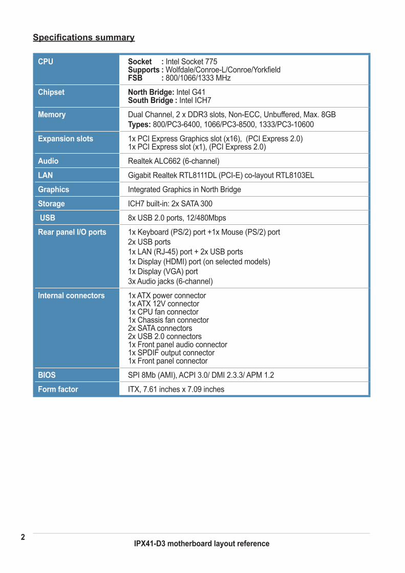
Specifications summary
CPU Socket : Intel Socket 775 Supports : Wolfdale/Conroe-L/Conroe/Yorkfield FSB : 800/1066/1333 MHz
Chipset North Bridge: Intel G41 South Bridge : Intel ICH7
Memory Dual Channel, 2 x DDR3 slots, Non-ECC, Unbuffered, Max. 8GB Types: 800/PC3-6400, 1066/PC3-8500, 1333/PC3-10600
Expansion slots 1x PCI Express Graphics slot (x16), (PCI Express 2.0) 1x PCI Express slot (x1), (PCI Express 2.0)
Audio Realtek ALC662 (6-channel)
LAN Gigabit Realtek RTL8111DL (PCI-E) co-layout RTL8103EL
Graphics Integrated Graphics in North Bridge
Storage ICH7 built-in: 2x SATA 300
USB 8x USB 2.0 ports, 12/480Mbps
Rear panel I/O ports 1x Keyboard (PS/2) port +1x Mouse (PS/2) port 2x USB ports 1x LAN (RJ-45) port + 2x USB ports 1x Display (HDMI) port (on selected models) 1x Display (VGA) port 3x Audio jacks (6-channel)
Internal connectors 1x ATX power connector 1x ATX 12V connector 1x CPU fan connector 1x Chassis fan connector 2x SATA connectors 2x USB 2.0 connectors 1x Front panel audio connector 1x SPDIF output connector 1x Front panel connector
BIOS SPI 8Mb (AMI), ACPI 3.0/ DMI 2.3.3/ APM 1.2
Form factor ITX, 7.61 inches x 7.09 inches
3IPX41-D3 motherboard layout reference
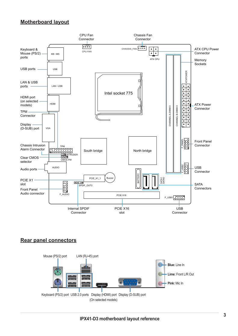
Motherboard layout
Rear panel connectors
Display (HDMI) port (On selected models)
Mouse (PS/2) port
Keyboard (PS/2) port
Blue: Line In
Lime: Front L/R Out
Pink: Mic In
Display (D-SUB) port
LAN (RJ-45) port
USB 2.0 ports
Keyboard &Mouse (PS/2)ports
Internal SPDIFConnector
USB ports
South bridge North bridge
Intel socket 775
LAN & USBports
Front PanelAudio connector
USBConnector
USBConnector
Front PanelConnector
ATX PowerConnector
ATX CPU PowerConnector
MemorySockets
SATAConnectors
CPU FanConnector
Chassis FanConnector
PCIE X16slot
PCIE X1slot
Display(D-SUB) port
Clear CMOSselector
Audio ports
F_USB1
PCIE_X1_1
AUDIO
F_AUDIO
LAN • USB
USB
VGA
SPDIF_OUT2
KB • MS
F_PA
NE
L
CMOS PW
F_U
SB
2
SAT
A0
SAT
A1
CH
AN
NE
L B
-DIM
M 0
CH
AN
NE
L A
-DIM
M 0
CPU FANCHASSIS_FAN
PCIE X16
Buzzer
BAT
TER
Y
ATX
PO
WE
R
ATX CPU
Chassis IntrusionAlarm Connector
INTRUDER
TPMConnector
HDMI port(on selected models)
TPM
HDMI
4IPX41-D3 motherboard layout reference
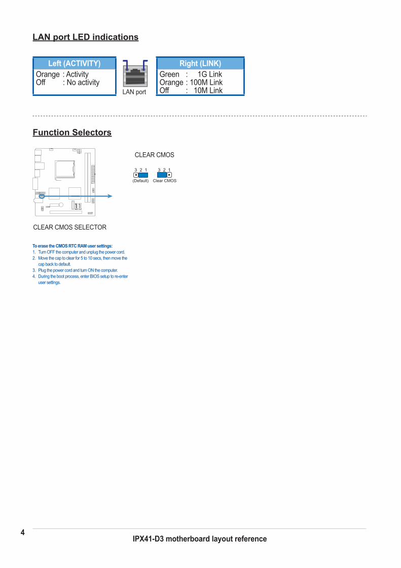
Function Selectors
LAN port LED indications
Left (ACTIVITY)Orange : Activity Off : No activity
Right (LINK)Green : 1G LinkOrange : 100M Link Off : 10M LinkLAN port
CLEAR CMOS SELECTOR
CLEAR CMOS
Clear CMOS(Default)
13 2 13 2
To erase the CMOS RTC RAM user settings:1. Turn OFF the computer and unplug the power cord.2. Move the cap to clear for 5 to 10 secs, then move the
cap back to default.3. Plug the power cord and turn ON the computer.4. During the boot process, enter BIOS setup to re-enter
user settings.
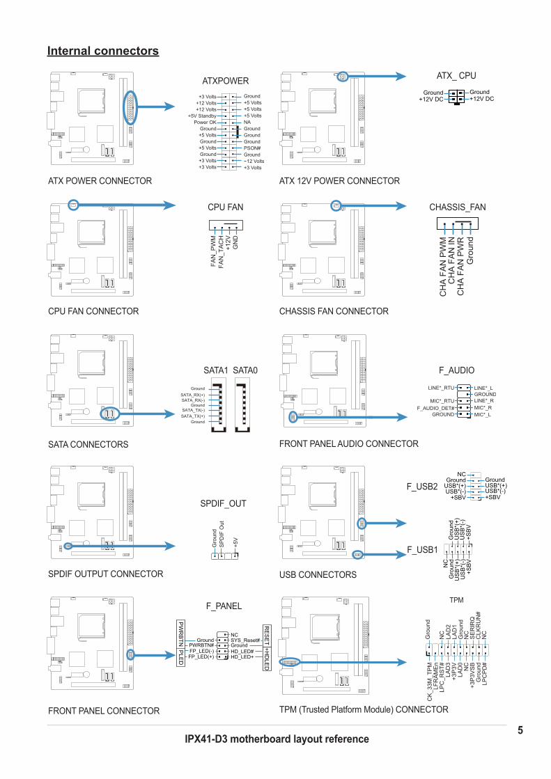
5IPX41-D3 motherboard layout reference
Internal connectors
CPU FAN CONNECTOR CHASSIS FAN CONNECTOR
FRONT PANEL AUDIO CONNECTOR
ATX POWER CONNECTOR ATX 12V POWER CONNECTOR
SATA CONNECTORS
SATA1 SATA0
MIC*_LMIC*_RLINE*_RGROUND
GROUND
LINE*_LLINE*_RTU
MIC*_RTUF_AUDIO_DET#
F_AUDIO
ATX_ CPU
+12V DCGroundGround
+12V DC
CHASSIS_FAN
Gro
und
CH
A F
AN
PW
MC
HA
FA
N IN
CH
A F
AN
PW
R
CPU FAN
GN
D+1
2VFA
N_T
AC
HFA
N_P
WM
SPDIF OUTPUT CONNECTOR
SPDIF_OUT
Gro
und
SP
DIF
Out
+5V
FRONT PANEL CONNECTOR
GroundGround
HD_LED+HD_LED#
FP_LED(+)FP_LED(-)
PWRBTN#SYS_Reset#NC
PW
RB
TNP
LED
+HD
LED
RE
SE
T
F_PANEL
ATXPOWER
+3 Volts
Power OKGround
Ground
Ground
Ground GroundGroundGround
GroundPSON#
+5 Volts+5 Volts
+5 VoltsNA
12 Volts
+3 Volts+12 Volts+12 Volts
+5V Standby
+5 Volts
+5 Volts
+3 Volts+3 Volts
Ground
Ground
Ground
SATA_RX(+)SATA_RX(-)
SATA_TX(-)SATA_TX(+)
USB CONNECTORS
F_USB2 USB*(-)USB*(+)USB*(+)
USB*(-)
GroundGround
+SBV+SBV
NC
US
B*(
-)U
SB
*(+)
US
B*(
+)U
SB
*(-)
Gro
und
Gro
und
+SB
V+S
BV
NC
F_USB1
TPM
CK
_33M
_TP
MG
roun
d
Gro
und
LPC
PD
#G
roun
d
LPC
_RS
T#LA
D3
LAD
1LA
D2
LAD
0+3
P3V
+3P
3VS
BN
C
NC
NC
NC
LFR
AM
En
SE
RIR
QC
LKR
UN
#
TPM (Trusted Platform Module) CONNECTOR
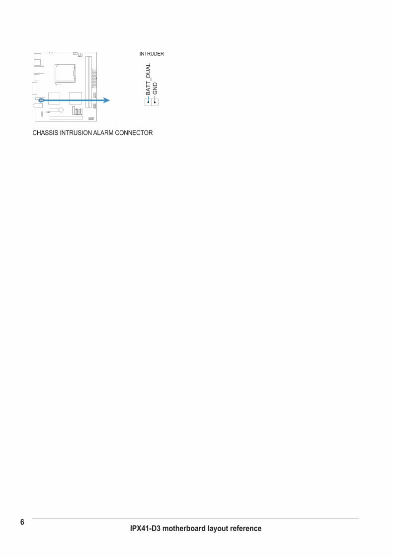
6IPX41-D3 motherboard layout reference
CHASSIS INTRUSION ALARM CONNECTOR
INTRUDER
BA
TT_D
UA
LG
ND