Embed Size (px)
Citation preview

Total maintenance solution
Bringing maintenance data management to the next level
iQ Platform-compatible PACSystem Recorder
Ethernet
1:55 19 220
1:55 19 220
1:55 19 220
1:55 19 220
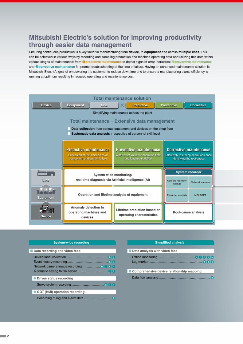
Mitsubishi Electric’s solution for improving productivity through easier data managementEnsuring continuous production is a key factor in manufacturing from device, to equipment and across multiple lines. This
can be achieved in various ways by recording and sampling production and machine operating data and utilizing this data within
various stages of maintenance; from ①predictive maintenance to detect signs of error, periodical ②preventive maintenance,
and ③corrective maintenance for prompt troubleshooting at the time of failure. Having an enhanced maintenance solution is
Mitsubishi Electric’s goal of empowering the customer to reduce downtime and to ensure a manufacturing plants efficiency is
running at optimum resulting in reduced operating and maintenance cost.
Line
Predictive maintenanceScheduled at the initial signs of component and system failure
Total maintenance = Extensive data management
Total maintenance solution
Simplifying maintenance across the plant
Preventive maintenanceWhen a set value for operation time
and load are satisfied
PreventivePredictiveDevice Equipment Line Corrective
Corrective maintenanceEffectively resuming operations once
identifying the root-cause
System recorderSystem-wide monitoring/
real-time diagnosis via Artificial Intelligence (AI)
Operation and lifetime analysis of equipment
Root-cause analysis
Anomaly detection in
operating machines and
devices
Lifetime prediction based on
operating characteristics
Equipment
Device
■ Data recording and video feed
Device/label collection .............................................. h j
Event history recording ............................................. h j
Network camera image recording .................... h j k l
Automatic saving to file server .................................. j l
● Drives status recording
Servo system recording .................................... a f i
● GOT (HMI) operation recording
Recording of log and alarm data .............................. g
System-wide recording Simplified analysis
■ Data analysis with video feed
Offline monitoring ......................................... a b d e h
Log marker .......................................................... a b c
■ Comprehensive device relationship mapping
Data flow analysis ......................................................... b
■ Data collection from various equipment and devices on the shop floor
■ Systematic data analysis irrespective of personnel skill level
Camera recorder module
Recorder module
Network camera
MELSOFT
2

Ethernet
1:55 19 220
1:55 19 220
1:55 19 220
1:55 19 220
System-wide recording and simplified analysis
Simplified analysis
■ Extensive data shown in the same timelineWaveform, data, program, operations log and video feeds
are shown in sequence ready for analysis.
■ Easier cause identificationData flow analysis makes understanding the root-cause of
failures easier by showing the relationship between failed
and normal devices.
■ Structured program ensures easier troubleshooting
Supports structured programs and device labels enabling
easier resolution of problems.
System-wide recording
■ Extensive recording ensures simpler cause analysis
Error cause identification is made simpler by the extensive
recording of various equipment and device data together
with a real-time video feed reducing the need for multiple
retesting due to insufficient data.
■ System-wideIrregularities between various equipment including control
and drive systems together with operations are all linked.
■ Automatic system-wide recordingRecording of errors that can occur outside standard
operating shifts.
h Programmable controller CPUi Motion module
j Camera recorder module or recorder module plus camera recording package
k Network camera
g GOT (HMI)/MELIPC MI3000
l File server*1
*1. NAS (Network-attached storage)
or computer
System recorder
The system recorder is a corrective maintenance solution that ensures effective resumption of operations reducing downtime
through its extensive system-wide data recording and simplified analysis software features.
Record entire system data
Programmable controller CPU (entire bit, word data, project data)Servo status (command position, actual position, speed, torque) Network camera video feedDisplay and operation log of GOT (HMI)
Program
Data
Video feed
GX Works3
GX LogViewer
GX VideoViewer
Cause of error
Error
t
i Servo amplifier
MELSOFTa GX LogViewerb GX Works3c GX VideoViewer
d GT Designer3e GT SoftGOT2000f MR Configurator2
3
■ Data recording and video feed
Complete system-wide recordingThe MELSEC iQ-R Series modules (supporting system recording) enables complete collection of all device changes per
controller scan time, therefore the error cause can be identified quickly. Collecting of all device data related to system modules
and network in addition to the programmable controller CPU is possible.
Easily locate error point with structured programSupporting structured programming enables the recording of not only devices but also labels. This eliminates concerns about
physical device addresses and system configuration, easily identifying the errors point of origin.
Record status changes from external devicesDevice and label operation from external devices can be recorded as historical events. This enables to accurately understand
status changes specifically for each device and label.
Select ideal camera for the applicationThe network camera is used to record a live feed of the actual behavior and status of the machine. Any problems specific to
the manufacturing process can be visualized easily. Various standard network cameras (compliant with industry standards) are
supported with no proprietary hardware required enabling the choice to select the ideal camera for the application.
Easier retention and analysis of overall dataCollected data (recording files) can be automatically stored on the SD memory card of the system recorder modules and on a file
server (such as NAS or computer) automatically based on the system configuration and data size.
● Drives status recording
Extensive recording of positional data from servoServo systems tend to operate at a much faster cycle time compared with a programmable controller making it difficult to capture.
Collecting data using a time-stamp ensures that detailed positional data from the servo can be recorded.
● Operator process recording
Operation logs and alarmsOperation logs can be recorded in the GOT (HMI) and MELIPC MI3000 in sequence. Alarms related to various devices can be
checked and archived.
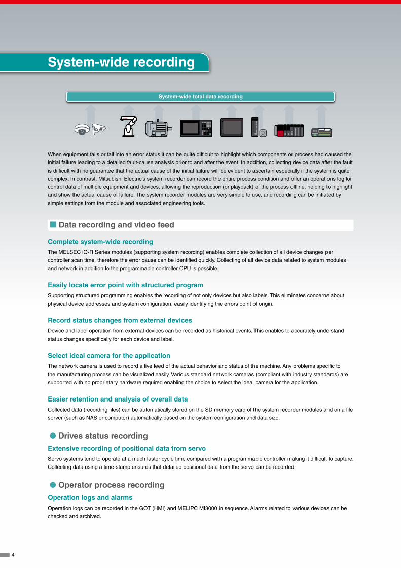
When equipment fails or fall into an error status it can be quite difficult to highlight which components or process had caused the
initial failure leading to a detailed fault-cause analysis prior to and after the event. In addition, collecting device data after the fault
is difficult with no guarantee that the actual cause of the initial failure will be evident to ascertain especially if the system is quite
complex. In contrast, Mitsubishi Electric’s system recorder can record the entire process condition and offer an operations log for
control data of multiple equipment and devices, allowing the reproduction (or playback) of the process offline, helping to highlight
and show the actual cause of failure. The system recorder modules are very simple to use, and recording can be initiated by
simple settings from the module and associated engineering tools.
System-wide recording
System-wide total data recording
4
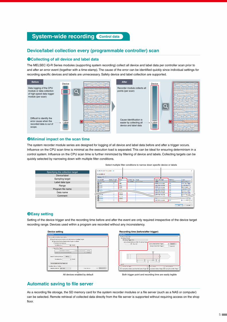
Device/label collection every (programmable controller) scan
①Collecting of all device and label dataThe MELSEC iQ-R Series modules (supporting system recording) collect all device and label data per controller scan prior to
and after an error event (together with a time-stamp). The cause of the error can be identified quickly since individual settings for
recording specific devices and labels are unnecessary. Safety device and label collection are supported.
System-wide recording Control data
Before After
Data logging of the CPU module or data collection of high-speed data logger module (per scan)
Recorder module collects all points (per scan)
Difficult to identify the error cause when the recorded data is out of scope.
Cause identification is easier by collecting all device and label data
Device
Label
Device
Label
②Minimal impact on the scan timeThe system recorder module series are designed for logging of all device and label data before and after a trigger occurs.
Influence on the CPU scan time is minimal as the execution load is separated. This can be ideal for ensuring determinism in a
control system. Influence on the CPU scan time is further minimized by filtering of device and labels. Collecting targets can be
quickly selected by narrowing down with multiple filter conditions.
Automatic saving to file server
As a recording file storage, the SD memory card for the system recorder modules or a file server (such as a NAS or computer)
can be selected. Remote retrieval of collected data directly from the file server is supported without requiring access on the shop
floor.
③Easy settingSetting of the device trigger and the recording time before and after the event are only required irrespective of the device target
recording range. Devices used within a program are recorded without any inconsistency.
Specifying the collection target
Device/label
Sampling target
Label data type
Range
Program file name
Data name
Comment
Select multiple filter conditions to narrow down specific device or labels
Device setting Recording time (before/after trigger)
All devices enabled by default Both trigger point and recording time are easily legible
5
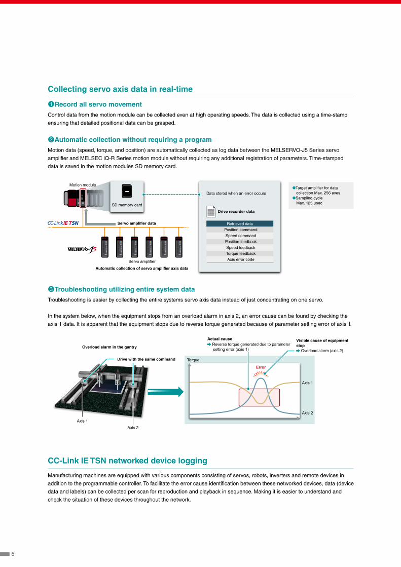
Collecting servo axis data in real-time
①Record all servo movementControl data from the motion module can be collected even at high operating speeds. The data is collected using a time-stamp
ensuring that detailed positional data can be grasped.
②Automatic collection without requiring a programMotion data (speed, torque, and position) are automatically collected as log data between the MELSERVO-J5 Series servo
amplifier and MELSEC iQ-R Series motion module without requiring any additional registration of parameters. Time-stamped
data is saved in the motion modules SD memory card.
SD memory card
Motion module
Data stored when an error occurs●Target amplifier for data
collection Max. 256 axes●Sampling cycle
Max. 125 μsec
Drive recorder data
Servo amplifier
Servo amplifier data
Automatic collection of servo amplifier axis data
Retrieved data
Position command
Speed command
Position feedback
Speed feedback
Torque feedback
Axis error code
Overload alarm in the gantry
Drive with the same command
Actual cause Reverse torque generated due to parameter setting error (axis 1)
Visible cause of equipment stop
Overload alarm (axis 2)
Error
Axis 1
Axis 2
Axis 1
Axis 2
Torque
③Troubleshooting utilizing entire system dataTroubleshooting is easier by collecting the entire systems servo axis data instead of just concentrating on one servo.
In the system below, when the equipment stops from an overload alarm in axis 2, an error cause can be found by checking the
axis 1 data. It is apparent that the equipment stops due to reverse torque generated because of parameter setting error of axis 1.
CC-Link IE TSN networked device logging
Manufacturing machines are equipped with various components consisting of servos, robots, inverters and remote devices in
addition to the programmable controller. To facilitate the error cause identification between these networked devices, data (device
data and labels) can be collected per scan for reproduction and playback in sequence. Making it is easier to understand and
check the situation of these devices throughout the network.
6

Event history
Sometimes an error may arise from sudden changes in data value from an external device or due to a mistake with an operator’s
procedure. Device and label operation from external devices can be recorded as historical events. This enables to accurately
understand status changes specifically for each device and label.
Record operation log and alarm history
①Easier to identify error cause from operation logOperation logs can be recorded in a SD or USB memory card from the GOT (HMI) in sequence. These logs can then be
confirmed in the GOT (HMI) or MELIPC MI3000 on the shop floor. In addition to authentication, recording of specific operator
logs can be identified easily.
System-wide recording Event history
Recorded items
Operation from engineering tool
Device and label data registration via SLMP*1 Ethernet protocol
Device and label data registration using instructions (from external station or machine)
Device and label registration using “Simple CPU communications” (from external device)
*1. SLMP: Seamless Message Protocol
②Recording of system alarm historySystem errors that have occurred are logged in the GOT (HMI) situated on the shop floor. Alarms related to each device with
detailed logs showing specific network station number are supported. These features are ideal for large-scale systems.
Operation log list
Check log profile
Detailed information
Image (GOT2000)
Focus on log
◀ Check log details
Check log image ▶
7

Utilize readily available network cameras
①Select network camera according to applicationsIn addition to operation and alarm logs, visual representation of errors in the form of a video feed are useful for showing actual
processes in operation enabling quick identification of a specific error or process issue. Network cameras can be installed around
equipment and/or processes enabling a real-time video feed close to the application. By supporting readily available network
cameras offers a broad choice of functions that maybe specific to an application, such as for process speed and environment
(ambient temperature, humidity, and installation space).
②Optimized focusing on camera subjectUtilize PTZ (Pan, Tilt, Zoom) functionality for network cameras. Enables large area monitoring and focusing on specific areas
of interest. Can be easily controlled from either the HMI (GOT) or MELIPC MI3000. Fine adjustments are supported while
monitoring the live video feed.
System-wide recording Camera images
Installation environment Applicable cameras
Recommended network cameras: • AXIS® COMMUNICATIONS (AXIS®) network camera*1
• ONVIF® Profile S compliant network camera
• Wide-area coverage capturing entire process area • Recording personnel operations
Wide angle/fish-eye lens type
• Detailed view • Multiple viewing positions
Optical zoom typePTZ (Pan-Tilt-Zoom) type
• Limited installation space • Difficulty installing communications cabling
Modular typeWireless type
*1. For more information, please contact your local Mitsubishi Electric sales office or representative.
③Long duration recordingRecording video feeds can require large storage capacity considering the frequency and amount of data being recorded.
To overcome this the system recorder stores video feeds using the H.264 codec which compresses the data making space
utilization more efficient. Together with GX VideoViewer feeds can be confirmed immediately.
④Use external storage such as a NAS or computerA file server (such as a NAS or computer) can be used as storage for camera images on the shop floor.
Wide angle/fish-eye lens type: Enables panoramic view of an entire production line
Optical zoom type: Provides detailed and vivid images PTZ (Pan-Tilt-Zoom) type: Pre-registered positions allowing multiple areas with a single camera.
Modular type: Installable within control enclosures with limited spaceWireless type: Greater installation flexibility as communication cables are not required
Simplified analysis
Pan
Zoom
Tilt
Camera (Live/PTZ) setting screen
8
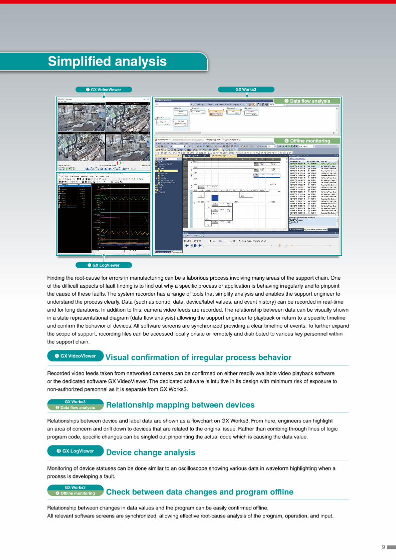
Finding the root-cause for errors in manufacturing can be a laborious process involving many areas of the support chain. One
of the difficult aspects of fault finding is to find out why a specific process or application is behaving irregularly and to pinpoint
the cause of these faults. The system recorder has a range of tools that simplify analysis and enables the support engineer to
understand the process clearly. Data (such as control data, device/label values, and event history) can be recorded in real-time
and for long durations. In addition to this, camera video feeds are recorded. The relationship between data can be visually shown
in a state representational diagram (data flow analysis) allowing the support engineer to playback or return to a specific timeline
and confirm the behavior of devices. All software screens are synchronized providing a clear timeline of events. To further expand
the scope of support, recording files can be accessed locally onsite or remotely and distributed to various key personnel within
the support chain.
① GX VideoViewer Visual confirmation of irregular process behavior
Recorded video feeds taken from networked cameras can be confirmed on either readily available video playback software
or the dedicated software GX VideoViewer. The dedicated software is intuitive in its design with minimum risk of exposure to
non-authorized personnel as it is separate from GX Works3.
GX Works3② Data flow analysis Relationship mapping between devices
Relationships between device and label data are shown as a flowchart on GX Works3. From here, engineers can highlight
an area of concern and drill down to devices that are related to the original issue. Rather than combing through lines of logic
program code, specific changes can be singled out pinpointing the actual code which is causing the data value.
③ GX LogViewer Device change analysis
Monitoring of device statuses can be done similar to an oscilloscope showing various data in waveform highlighting when a
process is developing a fault.
GX Works3④ Offline monitoring Check between data changes and program offline
Relationship between changes in data values and the program can be easily confirmed offline.
All relevant software screens are synchronized, allowing effective root-cause analysis of the program, operation, and input.
GX Works3
③ GX LogViewer
① GX VideoViewer
Simplified analysis
② Data flow analysis
④ Offline monitoring
9

⑤
①
②
③
④
⑤
GX VideoViewer GX LogViewer GX Works3 Log marker function
Faster cause analysis by synchronized video feed, program and waveform monitoring
①Register milestone points on the timeline
Milestone points (log marker) can be added to the main video
timeline enabling reference points for areas of concern. These points
can be saved for later use or for distributing amongst other support
personnel enabling multiple teams to analyze the problem area of
the application.
②Categorize registered milestone points
Log markers can be color-coded according to importance and event
type with support of commenting, realizing efficient analysis.
③Confirming video feed with collected data
Video feeds can be used to visually confirm areas that maybe
causing errors together with the program. The milestone points (log
marker) are synchronized with each tool and reproduced at different
playback speeds offering a realistic view of the process together
with the control data collected.
GX LogViewer GX Works3 GT Designer3 Offline monitoring
Synchronized playback of program, waveform data, GOT (HMI) (screens, operation logs, alarm history)Playback of data can be done very simply just by loading the recorded data into GX Works3, automatically executing all other
necessary tools. Using the “seek bar” enables to jump back and forth within the timeline synchronizing data between GX Works3
program monitoring (circuit monitor), GX LogViewer (waveform display), and GOT (HMI) “screens, operation logs, alarm history”.
Offline monitor (GX Works3)
GX LogViewerGOT offline monitor (GT Designer3)
MELSEC iQ-R Series
Event and waveform data when an alarm occurs
Program jump (synchronized with event)
Event jump (synchronized with seek bar)
Time synchronization
Seek bar
GOT (HMI)
Time synchronization
Color-coding (according to content)
Mouse over (showing comments)
Frame advance (by changing speed)
10

Ethernet
GX Works3 Data flow analysis function
①Visualize affected area of device/labelDevice and labels together with the affected area can be visualized within the flowchart. The process flow from comments,
instruction names, event history, and monitored values can be checked easily identifying the cause of an error.
②Bookmark milestone pointsEasily bookmark reference points for areas of concern.
③Main program languages supportedAnalysis can be done for ladder programs, function block diagram (FBD), SFC (within Zoom) and ST language programs.
Simplified analysis using panel computer
Multiple data can be reproduced on a panel computer such as the MELIPC MI3000 (embedded Windows® OS). Considering the
panel computer is situated on the shop floor, various historical alarms and operation logs can be confirmed efficiently at the point
where a problem occurs.
Simplified analysis of motion control
By loading the motion module data to GX LogViewer, the axis data shown as a waveform can be easily compared with the
programmable controller device data for analysis.
Camera recorder moduleRecorder module
Servo amplifier
MELSEC iQ-R Series
GOT (HMI) MELIPC (general computer)
or NAS
Network camera
GX Works3 GX LogViewer
GX VideoViewerGT Designer3
Data Flow Diagram
Ladder
FBD
ST
Bookmark calling
Monitor value display
Bookmark registration
11
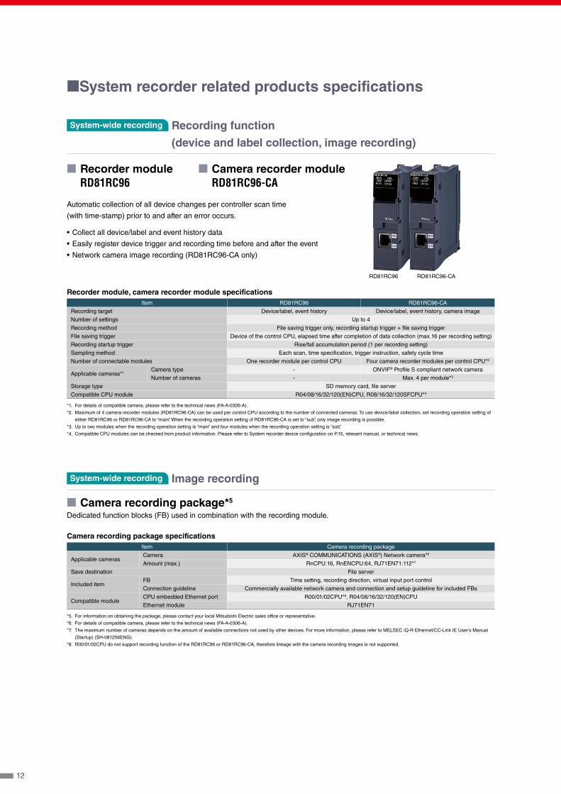
System-wide recording Recording function
(device and label collection, image recording)
System-wide recording Image recording
■ Camera recording package*5
Dedicated function blocks (FB) used in combination with the recording module.
Camera recording package specificationsItem Camera recording package
Applicable camerasCamera AXIS® COMMUNICATIONS (AXIS®) Network camera*6
Amount (max.) RnCPU:16, RnENCPU:64, RJ71EN71:112*7
Save destination File server
Included itemFB Time setting, recording direction, virtual input port control
Connection guideline Commercially available network camera and connection and setup guideline for included FBs
Compatible moduleCPU embedded Ethernet port R00/01/02CPU*8, R04/08/16/32/120(EN)CPU
Ethernet module RJ71EN71
*5. For information on obtaining the package, please contact your local Mitsubishi Electric sales office or representative.
*6. For details of compatible camera, please refer to the technical news (FA-A-0306-A).
*7. The maximum number of cameras depends on the amount of available connections not used by other devices. For more information, please refer to MELSEC iQ-R Ethernet/CC-Link IE User’s Manual
(Startup) (SH-081256ENG).
*8. R00/01/02CPU do not support recording function of the RD81RC96 or RD81RC96-CA, therefore linkage with the camera recording images is not supported.
■System recorder related products specifications
■ Recorder moduleRD81RC96
■ Camera recorder module RD81RC96-CA
Recorder module, camera recorder module specificationsItem RD81RC96 RD81RC96-CA
Recording target Device/label, event history Device/label, event history, camera image
Number of settings Up to 4
Recording method File saving trigger only, recording startup trigger + file saving trigger
File saving trigger Device of the control CPU, elapsed time after completion of data collection (max.16 per recording setting)
Recording startup trigger Rise/fall accumulation period (1 per recording setting)
Sampling method Each scan, time specification, trigger instruction, safety cycle time
Number of connectable modules One recorder module per control CPU Four camera recorder modules per control CPU*2
Applicable cameras*1Camera type - ONVIF® Profile S compliant network camera
Number of cameras - Max. 4 per module*3
Storage type SD memory card, file server
Compatible CPU module R04/08/16/32/120(EN)CPU, R08/16/32/120SFCPU*4
*1. For details of compatible camera, please refer to the technical news (FA-A-0326-A).
*2. Maximum of 4 camera recorder modules (RD81RC96-CA) can be used per control CPU according to the number of connected cameras. To use device/label collection, set recording operation setting of
either RD81RC96 or RD81RC96-CA to “main”. When the recording operation setting of RD81RC96-CA is set to “sub”, only image recording is possible.
*3. Up to two modules when the recording operation setting is “main” and four modules when the recording operation setting is “sub”.
*4. Compatible CPU modules can be checked from product information. Please refer to System recorder device configuration on P.15, relevant manual, or technical news.
RD81RC96 RD81RC96-CA
Automatic collection of all device changes per controller scan time
(with time-stamp) prior to and after an error occurs.
• Collect all device/label and event history data
• Easily register device trigger and recording time before and after the event
• Network camera image recording (RD81RC96-CA only)
12

Simplified analysis Offline monitor
■ GX Works3, GX LogViewer, GT Designer3Data/control program operation and GOT (HMI) display/operation log/alarm history can be displayed making it easier to visualize
an error.
Offline monitor specificationsItem Offline monitor
Play
Waveform data Selected device, label (GX LogViewer*2)
Control program Ladder diagram, ST, FBD/LD program (GX Works3*2)
GOT (HMI) screen GOT (HMI) screen status display (GT Designer3*2)
Operation log of GOT (HMI)/alarm history
Resource data (GT Designer3*2)
Operation bar/seek bar Move by seek bar
Monitor function Device block monitor, watch window, program monitor
Change point search Conditional search, display in a list (GX LogViewer*2)
Waveform displaySelected device/label displayed in waveform (GX LogViewer*2)
Device/label to be displayed Max. 32
*2. GX Works3 Ver.1.065T or later, GX LogViewer Ver.1.106K or later, GT Designer3 Ver.1.236W or later
System-wide recording Servo system recorder
■ Motion moduleRD78GHRD78G
■ Servo amplifierMR-J5 Series
Automatic collection of all servo control system drive axes data from the
motion module and servo amplifier when an error occurs. Can be used for easy
troubleshooting based on command and feedback values.
• Collect servo system recorder data without programming
• Data collection of all drive system axes
• Compare axis data with other logged data on GX LogViewerRD78GMR-J5-G
System-wide recording Network camera (Live/PTZ) setting screen
■ Camera adjustment on the operation panel*1 MI3000GOT2000 (GT27, GT25)
Sample screens supporting live image streaming and PTZ adjustment of the network
camera via the MELSEC iQ-R camera recorder module are available.*1. For information on obtaining the sample screens, please contact your local Mitsubishi Electric sales office or representative.
13
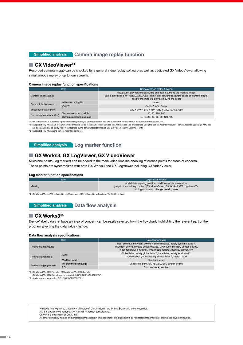
Simplified analysis Data flow analysis
■ GX Works3*5
Device/label data that have an area of concern can be easily selected from the flowchart, highlighting the relevant part of the
program affecting the data value change.
Data flow analysis specificationsItem Data flow analysis
Analysis target deviceUser device, safety user device*6, system device, safety system device*6,
link direct device, module access device, CPU buffer memory access device, index register, file register, refresh data register, nesting, pointer, etc.
Analysis target labelLabel
Global label, safety global label*6, local label, safety local label*6, module label, general/safety shared label*6, system label
Modified label Structure, array
Analysis target programProgramming language Ladder diagram, ST, FBD/LD, SFC (within Zoom)
POU Function block, function
*5. GX Works3 Ver.1.065T or later, GX LogViewer Ver.1.106K or later
GX Works3 Ver.1.070Y or later when using safety CPU R08/16/32/120SFCPU
*6. Available when using safety CPU R08/16/32/120SFCPU
Simplified analysis Log marker function
■ GX Works3, GX LogViewer, GX VideoViewerMilestone points (log marker) can be added to the main video timeline enabling reference points for areas of concern.
These points are synchronized with both GX Works3 and GX LogViewer including GX VideoViewer.
Log marker function specificationsItem Log marker function
MarkingAdd/delete marking position, read log marker information,
jump to the marking position (GX VideoViewer, GX Works3, GX LogViewer*4), adding comments, change marking color
*4. GX Works3 Ver. 1.072A or later, GX LogViewer Ver.1.106K or later, GX VideoViewer Ver.1.009K or later
Simplified analysis Camera image replay function
■ GX VideoViewer*1
Recorded camera image can be checked by a general video replay software as well as dedicated GX VideoViewer allowing
simultaneous replay of up to four screens.
Camera image replay function specificationsItem Camera image replay function
Camera image replayPlay/pause, play forward/backward one frame, jump to the marked image,
Select play speed (0.1/0.25/0.5/1/2/4/8x), select play forward/backward speed (1 frame/1 s/10 s)specify the image to play by moving the slider
Compatible file formatWithin recording file *.melrc
Video*2 *.mkv, *.mp4, *.mov
Image resolution (pixel) 320 x 240*3, 640 x 480, 1280 x 720, 1920 x 1080
Recording frame rate (fps)Camera recorder module 10, 30, 120, 200
Camera recording package 10, 15, 25, 30, 50, 60, 100, 120
*1. GX VideoViewer is successor (upper compatible product) to Video Verification Tool. Please use GX VideoViewer in place of Video Verification Tool.
*2. Supported only when XML files (with time stamp) are stored in the same folder as video files. When video files are recorded using the camera recorder module or camera recording package, XML files
are also generated. To replay video files recorded by the camera recorder module, use GX VideoViewer Ver.1.009K or later.
*3. Supported only when using camera recording package.
Windows is a registered trademark of Microsoft Corporation in the United States and other countries.AXIS is a registered trademark of Axis AB in various jurisdictions.ONVIF is a trademark of Onvif, Inc.All other company names and product names used in this document are trademarks or registered trademarks of their respective companies.
14

LOGLOGLOG
Ethernet
LOGLOGLOG
LOGLOGLOG
Ethernet
LOGLOGLOG
LOGLOGLOG
Basic configuration
Collecting of all device and label data
Collecting of all device and label data and recording instructions to network camera from software
Collecting of all device and label data, storage of video data from network camera
①MELSEC iQ-R Series CPU module*1
②Recorder module*2
③SD memory card
*1. CPU modules with product information (3rd and 4th digits) stated below support collecting of all device
and label data.Model Product information Model Product information Model Product information
R04CPU “19” or later R04ENCPU “32” or later R08SFCPU
“05” or laterR08CPU “20” or later R08ENCPU “30” or later R16SFCPUR16CPU “20” or later R16ENCPU “27” or later R32SFCPUR32CPU “17” or later R32ENCPU “30” or later R120SFCPUR120CPU “17” or later R120ENCPU “22” or later
For how to check product information, please refer to the MELSEC iQ-R Module Configuration Manual
SH-081262ENG. Module firmware update may be required depending on modules.
*2. GX Works3 (Ver.1.065T or later) is necessary for recording setting and module setting.
GX Works3 (Ver.1.070Y or later) is necessary when using RnSFCPU.
①MELSEC iQ-R Series CPU module*3
②Network camera*4
③Camera recording package (FB and guideline)
④Recorder module*5
⑤SD memory card or file server (NAS or computer)
⑥PoE switching hub (IEEE802.3at (PoE+) compliant)*6
*3. CPU modules with product information (3rd and 4th digits) stated below support collecting of all device
and label data. Model Product information Model Product information
R04CPU “19” or later R04ENCPU “32” or laterR08CPU “20” or later R08ENCPU “30” or laterR16CPU “20” or later R16ENCPU “27” or laterR32CPU “17” or later R32ENCPU “30” or laterR120CPU “17” or later R120ENCPU “22” or later
For how to check product information, please refer to the MELSEC iQ-R Module Configuration Manual
SH-081262ENG. Module firmware update may be required depending on modules.
To use camera image recording only, below CPU modules can be used.
• R00/01/02/04/08/16/32/120CPU, R04/08/16/32/120ENCPU (no restriction to product information)
• In addition to the above CPU Ethernet ports, the Ethernet module (RJ71EN71) can also be used
*4. For details of compatible AXIS® COMMUNICATIONS (AXIS®) Network cameras, please refer to the
technical news (FA-A-0306).
*5. GX Works3 (Ver.1.065T or later) is necessary for recording setting and module setting. GX Works3
(Ver.1.070Y or later) is necessary when using RnSFCPU.
*6. PoE: Power over Ethernet
①MELSEC iQ-R Series CPU module*7*8
②Network camera*9
③Camera recorder module*8
④SD memory card or file server (NAS or computer)
⑤PoE switching hub (IEEE802.3at (PoE+) compliant)
*7. CPU modules with product information (3rd and 4th digits) stated below support collecting of all device
and label data. Model Product information Model Product information Model Product information
R04CPU “19” or later R04ENCPU “32” or later R08SFCPU
“05” or laterR08CPU “20” or later R08ENCPU “30” or later R16SFCPUR16CPU “20” or later R16ENCPU “27” or later R32SFCPUR32CPU “17” or later R32ENCPU “30” or later R120SFCPUR120CPU “17” or later R120ENCPU “22” or later
For how to check product information, please refer to the MELSEC iQ-R Module Configuration Manual
SH-081262ENG. Module firmware update may be required depending on modules.
*8. GX Works3 (Ver.1.072A or later) is necessary for recording setting and module and camera setting (not
yet supported).
*9. For details of ONVIF® Profile S compatible network camera and other compatible cameras, please refer
to the technical news (FA-A-0326-A).
■System recorder device configuration
①
①
①
⑤
④
⑥
⑤
⑤
④
②
②
③
④
③
②③
Basic configuration + Camera recording package
Basic configuration + Camera recorder module
15

Country/Region Sales office Tel/FaxUSA MITSUBISHI ELECTRIC AUTOMATION, INC.
500 Corporate Woods Parkway, Vernon Hills, IL 60061, U.S.A.Tel : +1-847-478-2100Fax : +1-847-478-2253
Mexico MITSUBISHI ELECTRIC AUTOMATION, INC. Mexico BranchBoulevard Miguel de Cervantes Saavedra 301, Torre Norte Piso 5, Ampliacion Granada, Miguel Hidalgo, Ciudad de Mexico, Mexico, C.P.115200
Tel : +52-55-3067-7512
Brazil MITSUBISHI ELECTRIC DO BRASIL COMERCIO E SERVICOS LTDA.Avenida Adelino Cardana, 293, 21 andar, Bethaville, Barueri SP, Brasil
Tel : +55-11-4689-3000Fax : +55-11-4689-3016
Germany MITSUBISHI ELECTRIC EUROPE B.V. German BranchMitsubishi-Electric-Platz 1, 40882 Ratingen, Germany
Tel : +49-2102-486-0Fax : +49-2102-486-7780
UK MITSUBISHI ELECTRIC EUROPE B.V. UK BranchTravellers Lane, UK-Hatfield, Hertfordshire, AL10 8XB, U.K.
Tel : +44-1707-28-8780Fax : +44-1707-27-8695
Ireland MITSUBISHI ELECTRIC EUROPE B.V. Irish BranchWestgate Business Park, Ballymount, Dublin 24, Ireland
Tel : +353-1-4198800Fax : +353-1-4198890
Italy MITSUBISHI ELECTRIC EUROPE B.V. Italian BranchCentro Direzionale Colleoni - Palazzo Sirio, Viale Colleoni 7, 20864 Agrate Brianza (MB), Italy
Tel : +39-039-60531Fax : +39-039-6053-312
Spain MITSUBISHI ELECTRIC EUROPE, B.V. Spanish BranchCarretera de Rubi, 76-80-Apdo. 420, E-08190 Sant Cugat del Valles (Barcelona), Spain
Tel : +34-935-65-3131Fax : +34-935-89-1579
France MITSUBISHI ELECTRIC EUROPE B.V. French Branch25, Boulevard des Bouvets, 92741 Nanterre Cedex, France
Tel : +33-1-55-68-55-68Fax : +33-1-55-68-57-57
Czech Republic MITSUBISHI ELECTRIC EUROPE B.V. Czech Branch, Prague OfficePekarska 621/7, 155 00 Praha 5, Czech Republic
Tel : +420-255-719-200
Poland MITSUBISHI ELECTRIC EUROPE B.V. Polish Branchul. Krakowska 48, 32-083 Balice, Poland
Tel : +48-12-347-65-00
Sweden MITSUBISHI ELECTRIC EUROPE B.V. (Scandinavia)Hedvig Mollersgata 6, 223 55 Lund, Sweden
Tel : +46-8-625-10-00Fax : +46-46-39-70-18
Russia MITSUBISHI ELECTRIC (RUSSIA) LLC St. Petersburg BranchPiskarevsky pr. 2, bld 2, lit “Sch”, BC “Benua”, office 720; 195027 St. Petersburg, Russia
Tel : +7-812-633-3497Fax : +7-812-633-3499
Turkey MITSUBISHI ELECTRIC TURKEY A.S. Umraniye BranchSerifali Mah. Kale Sok. No:41 34775 Umraniye - Istanbul, Turkey
Tel : +90-216-969-2500Fax : +90-216-661-4447
UAE MITSUBISHI ELECTRIC EUROPE B.V. Dubai BranchDubai Silicon Oasis, P.O.BOX 341241, Dubai, U.A.E.
Tel : +971-4-3724716Fax : +971-4-3724721
South Africa ADROIT TECHNOLOGIES 20 Waterford Office Park, 189 Witkoppen Road, Fourways, South Africa
Tel : +27-11-658-8100Fax : +27-11-658-8101
China MITSUBISHI ELECTRIC AUTOMATION (CHINA) LTD.Mitsubishi Electric Automation Center, No.1386 Hongqiao Road, Shanghai, China
Tel : +86-21-2322-3030Fax : +86-21-2322-3000
Taiwan SETSUYO ENTERPRISE CO., LTD.6F, No.105, Wugong 3rd Road, Wugu District, New Taipei City 24889, Taiwan
Tel : +886-2-2299-2499Fax : +886-2-2299-2509
Korea MITSUBISHI ELECTRIC AUTOMATION KOREA CO., LTD.7F to 9F, Gangseo Hangang Xi-tower A, 401, Yangcheon-ro, Gangseo-Gu, Seoul 07528, Korea
Tel : +82-2-3660-9569Fax : +82-2-3664-8372
Singapore MITSUBISHI ELECTRIC ASIA PTE. LTD.307 Alexandra Road, Mitsubishi Electric Building, Singapore 159943
Tel : +65-6473-2308Fax : +65-6476-7439
Thailand MITSUBISHI ELECTRIC FACTORY AUTOMATION (THAILAND) CO., LTD.12th Floor, SV.City Building, Office Tower 1, No. 896/19 and 20 Rama 3 Road, Kwaeng Bangpongpang, Khet Yannawa, Bangkok 10120, Thailand
Tel : +66-2682-6522-31Fax : +66-2682-6020
Vietnam MITSUBISHI ELECTRIC VIETNAM COMPANY LIMITEDUnit 01-04, 10th Floor, Vincom Center, 72 Le Thanh Ton Street, District 1, Ho Chi Minh City, Vietnam
Tel : +84-28-3910-5945Fax : +84-28-3910-5947
Indonesia PT. MITSUBISHI ELECTRIC INDONESIAGedung Jaya 8th Floor, JL. MH. Thamrin No.12, Jakarta Pusat 10340, Indonesia
Tel : +62-21-31926461Fax : +62-21-31923942
India MITSUBISHI ELECTRIC INDIA PVT. LTD. Pune BranchEmerald House, EL-3, J Block, M.I.D.C., Bhosari, Pune-411026, Maharashtra, India
Tel : +91-20-2710-2000Fax : +91-20-2710-2100
Australia MITSUBISHI ELECTRIC AUSTRALIA PTY. LTD.348 Victoria Road, P.O. Box 11, Rydalmere, N.S.W 2116, Australia
Tel : +61-2-9684-7777Fax : +61-2-9684-7245
HEAD OFFICE: TOKYO BLDG., 2-7-3, MARUNOUCHI, CHIYODA-KU, TOKYO 100-8310, JAPAN
www.MitsubishiElectric.com
L(NA)08736ENG-E 2108(IP)New publication, effective August 2021.
Specifications are subject to change without notice.