Embed Size (px)
Citation preview

IQ-Modbus Master
Configuration
Version 2.0a15. mar. 2011
ElectrocomRødeledsvej 95DK-5700 SvendborgDenmarkTel : +45 8880 7580www.electrocom.dk

p. 2
Installation
NOTE! It is important that the IQ-Modbus Master and the Modbus Slaves have same ground potential for the supply and the communication line.
Power Supply:Via TREND Supervisor Port:The IQ-Modbus Master can be supplied directly via the communication cable from the TREND IQ.
NOTE! - Works not with the IQ251- A TREND IQ can max deliver 100mA DC. The IQ-Modbus Master uses 50mA. If the TREND IQ supplies other DC loads, additional supply with an external 24VDC and 24VAC or to the IQ-Modbus Master can be nessasary.
Via 24V AC/DC:Alternatively the IQ-Modbus Master can be supplied by 24VDC or 24VAC. This is connected to the Power terminals “~” 24VDC/24VAC and “0”.
NOTE! Ground potential(”GND”, ”0V”) MUST be potential equal to ground on the TREND IQ.
Bus topology:
RS485 2 wire:For RS485 2 wire multi drop network, connect terminals RS485 A / B on the IQ-Modbus Master with corresponding A and B (Rx or Tx, recieve or transmit) terminals on the Modbus Slave Unit. Due to differences in naming conventions, it might be nessasary to switch the wires.
IQ-Modbus Master Modbus SlaveA A ( or B)B B ( or A)0 (Ground) (Power terminals) or GND (MPbus terminals)
GND
NOTE! Due to the “2 wire” naming it is still necessary to connect GND to the Modbus Slaves.The RS485 network may require termination in both ends of the network. The IQ-Modbus Master features onboard 120 Ohm resistor termination. Use twisted pair cable with characteristic impedance of 120 Ohm.
p. 3
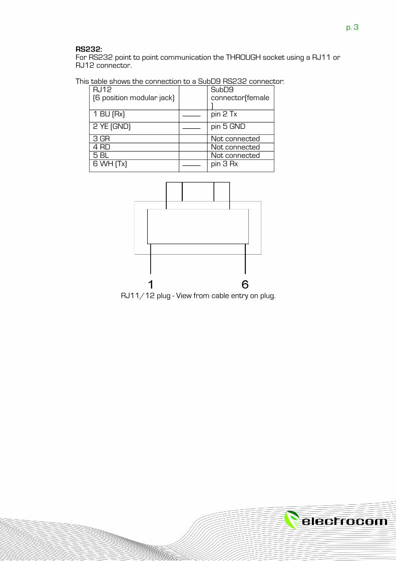
RS232:For RS232 point to point communication the THROUGH socket using a RJ11 or RJ12 connector.
This table shows the connection to a SubD9 RS232 connector:RJ12(6 position modular jack)
SubD9 connector(female)
1 BU (Rx) pin 2 Tx
2 YE (GND) pin 5 GND
3 GR Not connected4 RD Not connected5 BL Not connected6 WH (Tx) pin 3 Rx
RJ11/12 plug - View from cable entry on plug.

p. 4
Three Step Configuration of Modbus Master
The IQ-Modbus Master can be configured according to the Modbus standard. The available communication standards are via RS232 and RS485. RTU package format is supported at the moment. Function 1 – 6, 15 and 16 are supported at the moment. The IQ-Modbus Master (hereafter called the Modbus Master) continuously synchronises registers in Modbus slaves attached to the Modbus Master with sensors or anodes in the IQ. Synchronization is performed from selected mapping between sensors or anodes and Modbus slave addresses an registers. These relations are called mappings. The mappings are configured via a PC with a terminal program (eg. Windows HyperTerminal) and a Tool Cable provided by ElectroCom.
To configure the Modbus Master use the following steps:
1. Connect IQ-Modbus Master to PC with Tool Cable.2. Configuration of Modbus communication port.3. Configuration of slave register to IQ mappings.---4. Create Sensors or Anode registers in TREND IQ3 or IQ3XNC.

p. 5
Step 1 – Connect IQ-Modbus Master to PC
Connect the Tool Cable to the RS232(DB9) port on the PC and insert the RJ11 plug into socket THROUGH on the IQ-Modbus Master. When the terminal program connects the IQ-Modbus Master enters configuration mode. The Modbus Master can be forced into configuration mode by placing a jumper on JP5.
If using Windows HyperTerminal, see the section “Setting up HyperTerminal for Modbus Master configuration”. Communication settings are:Baud rate: 9600Data bits: 8Stop bits: 1Parity: NONE
When connected you should see the following menu. If not, try to hit [Enter] to refresh the menu.
ElectroCom (c) 2009Modbus Master 2.0a
List mappings (L)Set mapping (S)Delete mapping (D)Show Anodes (A)Modbus Port (R) _
The menu is described in the following sections.
p. 6
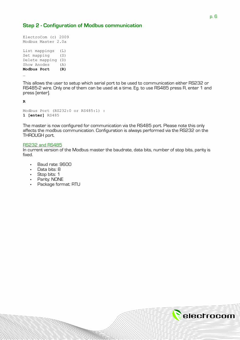
Step 2 - Configuration of Modbus communication
ElectroCom (c) 2009Modbus Master 2.0a
List mappings (L)Set mapping (S)Delete mapping (D)Show Anodes (A)Modbus Port (R) _
This allows the user to setup which serial port to be used to communication either RS232 or RS485-2 wire. Only one of them can be used at a time. Eg. to use RS485 press R, enter 1 and press [enter].
R
Modbus Port (RS232:0 or RS485:1) :1 [enter] RS485
The master is now configured for communication via the RS485 port. Please note this only affects the modbus communication. Configuration is always performed via the RS232 on the THROUGH port.
RS232 and RS485In current version of the Modbus master the baudrate, data bits, number of stop bits, parity is fixed.
• Baud rate: 9600• Data bits: 8• Stop bits: 1• Parity: NONE• Package format: RTU
p. 7
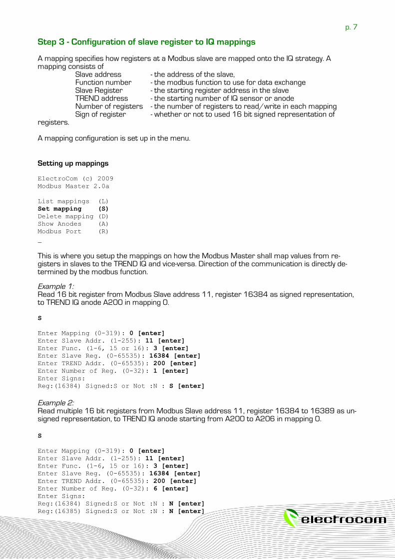
Step 3 - Configuration of slave register to IQ mappings
A mapping specifies how registers at a Modbus slave are mapped onto the IQ strategy. A mapping consists of
Slave address - the address of the slave, Function number - the modbus function to use for data exchangeSlave Register - the starting register address in the slaveTREND address - the starting number of IQ sensor or anode Number of registers - the number of registers to read/write in each mappingSign of register - whether or not to used 16 bit signed representation of
registers.
A mapping configuration is set up in the menu.
Setting up mappings
ElectroCom (c) 2009Modbus Master 2.0a
List mappings (L)Set mapping (S)Delete mapping (D)Show Anodes (A)Modbus Port (R) _
This is where you setup the mappings on how the Modbus Master shall map values from re-gisters in slaves to the TREND IQ and vice-versa. Direction of the communication is directly de-termined by the modbus function.
Example 1: Read 16 bit register from Modbus Slave address 11, register 16384 as signed representation, to TREND IQ anode A200 in mapping 0.
S
Enter Mapping (0-319): 0 [enter]Enter Slave Addr. (1-255): 11 [enter]Enter Func. (1-6, 15 or 16): 3 [enter]Enter Slave Reg. (0-65535): 16384 [enter]Enter TREND Addr. (0-65535): 200 [enter]Enter Number of Reg. (0-32): 1 [enter]Enter Signs: Reg:(16384) Signed:S or Not :N : S [enter]
Example 2: Read multiple 16 bit registers from Modbus Slave address 11, register 16384 to 16389 as un-signed representation, to TREND IQ anode starting from A200 to A206 in mapping 0.
S
Enter Mapping (0-319): 0 [enter]Enter Slave Addr. (1-255): 11 [enter]Enter Func. (1-6, 15 or 16): 3 [enter]Enter Slave Reg. (0-65535): 16384 [enter]Enter TREND Addr. (0-65535): 200 [enter]Enter Number of Reg. (0-32): 6 [enter]Enter Signs: Reg:(16384) Signed:S or Not :N : N [enter]Reg:(16385) Signed:S or Not :N : N [enter]
p. 8
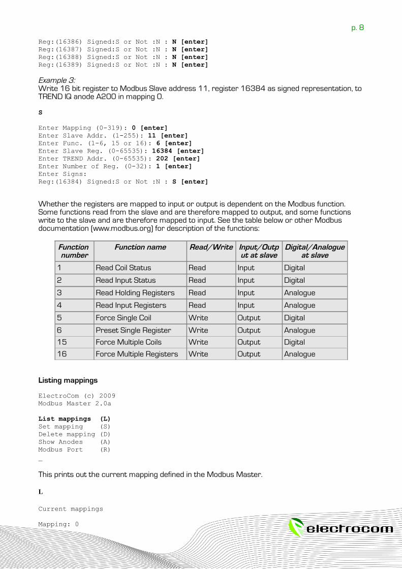
Reg:(16386) Signed:S or Not :N : N [enter]Reg:(16387) Signed:S or Not :N : N [enter]Reg:(16388) Signed:S or Not :N : N [enter]Reg:(16389) Signed:S or Not :N : N [enter]
Example 3: Write 16 bit register to Modbus Slave address 11, register 16384 as signed representation, to TREND IQ anode A200 in mapping 0.
S
Enter Mapping (0-319): 0 [enter]Enter Slave Addr. (1-255): 11 [enter]Enter Func. (1-6, 15 or 16): 6 [enter]Enter Slave Reg. (0-65535): 16384 [enter]Enter TREND Addr. (0-65535): 202 [enter]Enter Number of Reg. (0-32): 1 [enter]Enter Signs: Reg:(16384) Signed:S or Not :N : S [enter]
Whether the registers are mapped to input or output is dependent on the Modbus function. Some functions read from the slave and are therefore mapped to output, and some functions write to the slave and are therefore mapped to input. See the table below or other Modbus documentation (www.modbus.org) for description of the functions:
Function number
Function name Read/Write Input/Output at slave
Digital/Analogueat slave
1 Read Coil Status Read Input Digital
2 Read Input Status Read Input Digital
3 Read Holding Registers Read Input Analogue
4 Read Input Registers Read Input Analogue
5 Force Single Coil Write Output Digital
6 Preset Single Register Write Output Analogue
15 Force Multiple Coils Write Output Digital
16 Force Multiple Registers Write Output Analogue
Listing mappings
ElectroCom (c) 2009Modbus Master 2.0a
List mappings (L)Set mapping (S)Delete mapping (D)Show Anodes (A)Modbus Port (R) _
This prints out the current mapping defined in the Modbus Master.
L
Current mappings
Mapping: 0
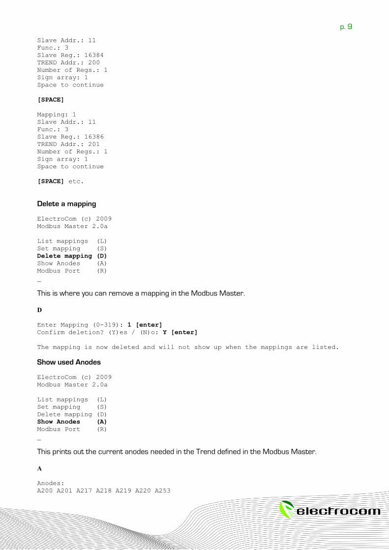
p. 9
Slave Addr.: 11Func.: 3Slave Reg.: 16384TREND Addr.: 200Number of Regs.: 1Sign array: 1Space to continue
[SPACE]
Mapping: 1Slave Addr.: 11Func.: 3Slave Reg.: 16386TREND Addr.: 201Number of Regs.: 1Sign array: 1Space to continue
[SPACE] etc.
Delete a mapping
ElectroCom (c) 2009Modbus Master 2.0a
List mappings (L)Set mapping (S)Delete mapping (D)Show Anodes (A)Modbus Port (R)_
This is where you can remove a mapping in the Modbus Master.
D
Enter Mapping (0-319): 1 [enter]Confirm deletion? (Y)es / (N)o: Y [enter]
The mapping is now deleted and will not show up when the mappings are listed.
Show used Anodes
ElectroCom (c) 2009Modbus Master 2.0a
List mappings (L)Set mapping (S)Delete mapping (D)Show Anodes (A)Modbus Port (R)_
This prints out the current anodes needed in the Trend defined in the Modbus Master.
A
Anodes:A200 A201 A217 A218 A219 A220 A253
p. 10
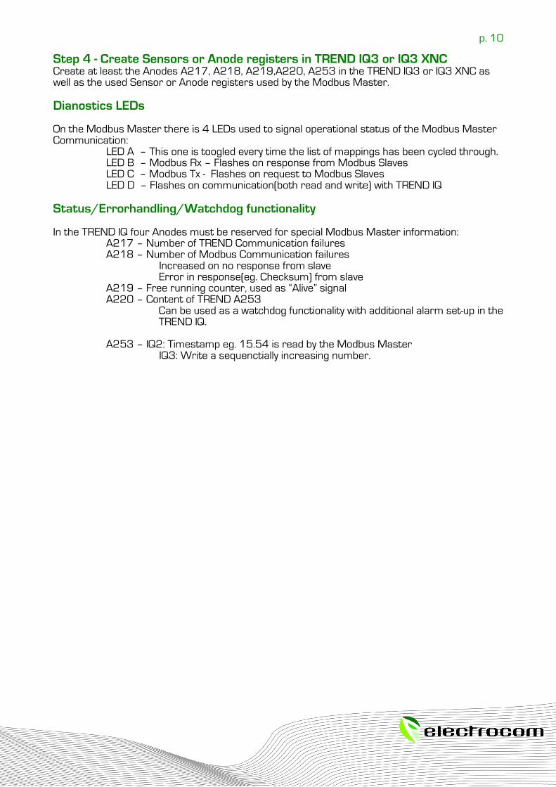
Step 4 - Create Sensors or Anode registers in TREND IQ3 or IQ3 XNCCreate at least the Anodes A217, A218, A219,A220, A253 in the TREND IQ3 or IQ3 XNC as well as the used Sensor or Anode registers used by the Modbus Master.
Dianostics LEDs
On the Modbus Master there is 4 LEDs used to signal operational status of the Modbus Master Communication:
LED A – This one is toogled every time the list of mappings has been cycled through.LED B – Modbus Rx – Flashes on response from Modbus SlavesLED C – Modbus Tx - Flashes on request to Modbus SlavesLED D – Flashes on communication(both read and write) with TREND IQ
Status/Errorhandling/Watchdog functionality
In the TREND IQ four Anodes must be reserved for special Modbus Master information:A217 – Number of TREND Communication failuresA218 – Number of Modbus Communication failures
Increased on no response from slaveError in response(eg. Checksum) from slave
A219 – Free running counter, used as “Alive” signalA220 – Content of TREND A253
Can be used as a watchdog functionality with additional alarm set-up in the TREND IQ.
A253 – IQ2: Timestamp eg. 15.54 is read by the Modbus MasterIQ3: Write a sequenctially increasing number.

p. 11
Setting up HyperTerminal for Modbus Master configurationIn a normal installation of Windows XP, Hyperterminal is automatically installed under Programs:Accessories, so you access it as follows:
• Click Start• Select Programs • Select Accessories • Select Hyperterminal folder • Select Hypertrm.exe
Upon launching Hyperterminal, you will be given the opportunity to name and assign an icon to your settings. You may choose any name/icon. Afterwards, a series of dialog boxes will appear. Enter the following settings:
Phone Number• Click the drop-down arrow by Connect Using • Select Direct to COM1 (or 'direct to' the port you intend to use) • Click OK
COM1 Properties, Port Settings• Bits per Second: select 9600• Data Bits: select 8 • Parity: select None • Stop Bits: select 1 • Flow Control: select none • Click OK
This will get you into the main Hyperterminal window.
p. 12
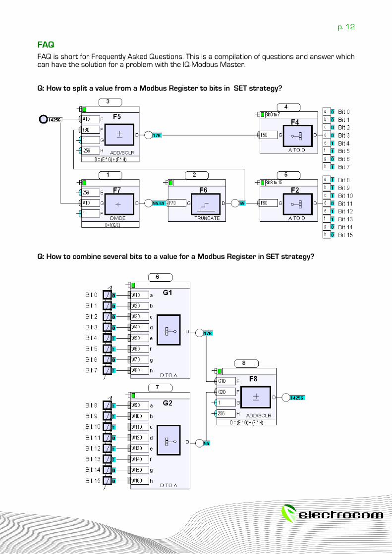
FAQFAQ is short for Frequently Asked Questions. This is a compilation of questions and answer which can have the solution for a problem with the IQ-Modbus Master.
Q: How to split a value from a Modbus Register to bits in SET strategy?
Q: How to combine several bits to a value for a Modbus Register in SET strategy?