Embed Size (px)
Citation preview
User guide www.IQtronic.com
User
Guide
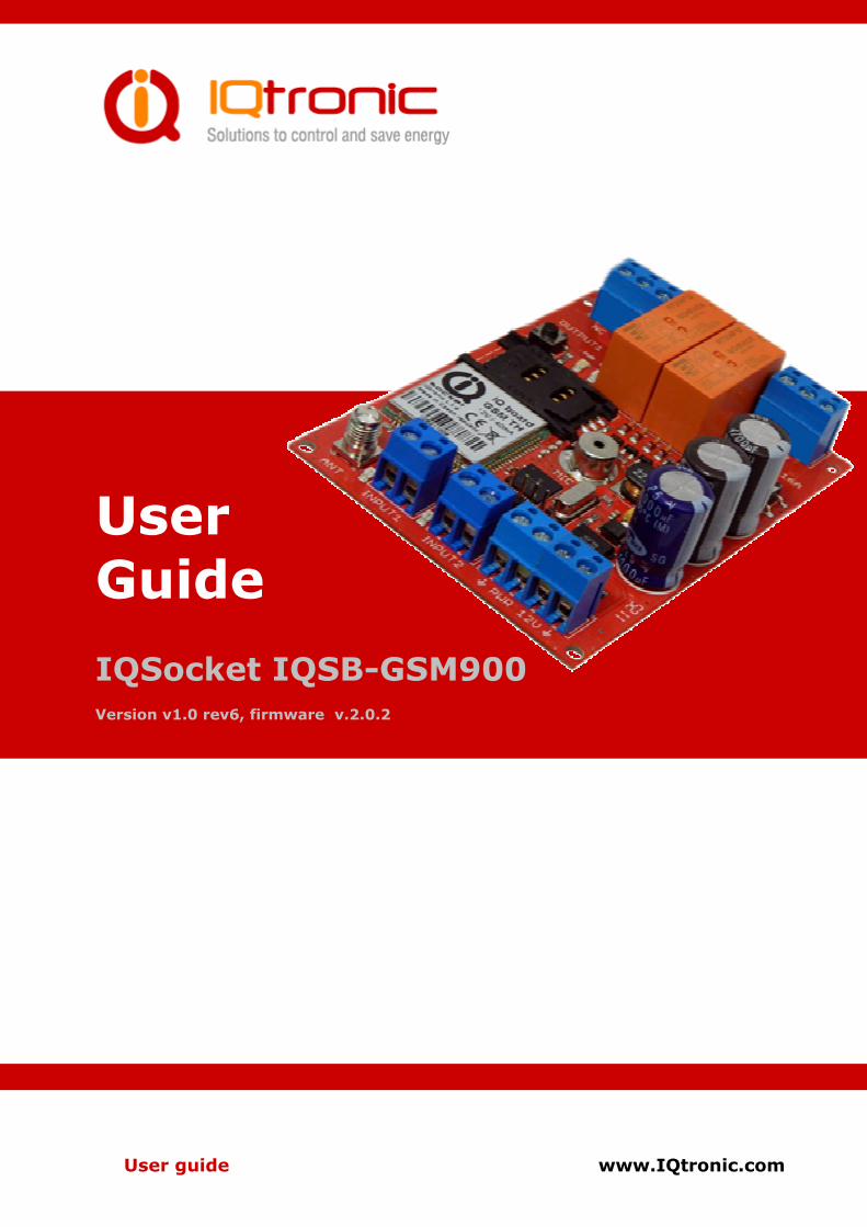
IQSocket IQSB-GSM900 Version v1.0 rev6, firmware v.2.0.2
User guide www.IQtronic.com
1.1 Important information...................................................................4
2 Introduction ....................................................................5
2.1 Product features...........................................................................6
3 Installation......................................................................7
3.1 Inserting SIM Card .......................................................................7
3.2 Wiring the IQsocket IQSB-GSM900 .................................................8
3.2.1 Outputs wiring......................................................................8
3.2.2 Inputs wiring........................................................................9
3.2.3 Power supply wiring ............................................................10
3.3 Powering IQSB-GSM900 On .........................................................11
4 Managing IQSB-GSM900................................................12
4.1 Managing by SMS .......................................................................12
4.2 Managing by phone call ...............................................................14
4.2.1 Control using DTMF .............................................................14
Manual Control ...............................................................................16
4.3 Timing setup..............................................................................17
4.3.1 RESTARTTTIME...................................................................17
4.3.2 RINGONTIME......................................................................17
4.4 Date/Time setup.........................................................................18
4.5 Security features ........................................................................18
4.6 Response messages settings ........................................................20
4.7 Scheduler feature .......................................................................21
4.8 Counters ...................................................................................22
4.9 Alarms ......................................................................................23
4.9.1 Defining phone numbers for SMS and ringing up alerts.............23
4.9.2 Alarm invoked by Inputs ......................................................24
4.9.3 Temperature alarm .............................................................26
4.9.4 Humidity alarm...................................................................27
4.9.5 Power supply voltage drop alarm...........................................27
4.9.6 Change of GSM BTS alarm....................................................28
4.9.7 Disabling all alarms .............................................................28
4.10 Using microphone ....................................................................28
4.11 Various other settings...............................................................29
4.12 Error messages........................................................................30
5 Indicators......................................................................31
6 Factory default settings.................................................32
6.1 Reset to factory default procedure ................................................32
6.2 Factory default settings ...............................................................32
7 Technical specification ..................................................33
7.1 Operation, maintenance and safety recommendations .....................34
8 Ordering and accessories ..............................................35

©2011 IQtronic, Ltd
Page 3 of 35
©2011 IQtronic, Ltd
Page 4 of 35
1.1 Important information Every effort has been taken to ensure the accuracy of this document, however we do not accept responsibility for damage, injury, loss or expense resulting from errors and omissions, and we reserve the right of amendment without further notice. WARNING: This product is not designed for use in, and should not be used for, medical applications. Product must be mounted inside a suitable enclosure providing environmental protection. The product doesn’t guarantee safe power source disconnection, only functional switching of power is performed. The product contains no serviceable parts, or internal adjustments. No attempt must be made to repair this product. Faulty units must be returned to supplier for repair. Improper use, disassembling or product modification causes warranty loss. This product must be installed by a qualified person. All electrical wiring must be carried out in accordance with the appropriate regulations for the place of installation. Before attempting any electrical connection work, please ensure all supplies are switched off.
©2011 IQtronic, Ltd
Page 5 of 35
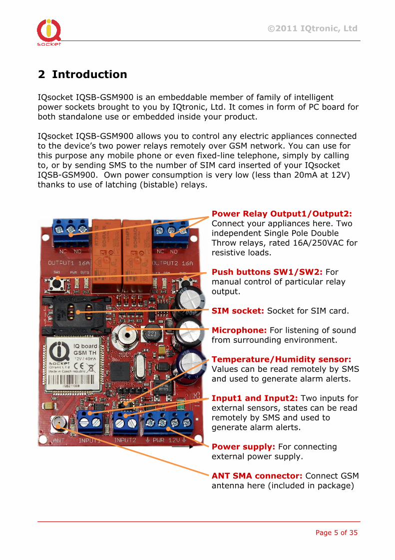
2 Introduction IQsocket IQSB-GSM900 is an embeddable member of family of intelligent power sockets brought to you by IQtronic, Ltd. It comes in form of PC board for both standalone use or embedded inside your product. IQsocket IQSB-GSM900 allows you to control any electric appliances connected to the device’s two power relays remotely over GSM network. You can use for this purpose any mobile phone or even fixed-line telephone, simply by calling to, or by sending SMS to the number of SIM card inserted of your IQsocket IQSB-GSM900. Own power consumption is very low (less than 20mA at 12V) thanks to use of latching (bistable) relays.
Power Relay Output1/Output2: Connect your appliances here. Two independent Single Pole Double Throw relays, rated 16A/250VAC for resistive loads.
Push buttons SW1/SW2: For manual control of particular relay output.
SIM socket: Socket for SIM card. Microphone: For listening of sound from surrounding environment. Temperature/Humidity sensor: Values can be read remotely by SMS and used to generate alarm alerts. Input1 and Input2: Two inputs for external sensors, states can be read remotely by SMS and used to generate alarm alerts. Power supply: For connecting external power supply.
ANT SMA connector: Connect GSM antenna here (included in package)
©2011 IQtronic, Ltd
Page 6 of 35
Besides controlling power, IQsocket IQSB-GSM900 is equipped with a choice of useful functions, including: • Remote monitoring of environment using on-board temperature and relative humidity sensors
• Remote monitoring of status of two digital inputs, tailored to connect with external sensors such as PIR motion detectors, door contacts, water level sensors and so on.
• Sending alarm alerts based on status of two digital inputs; levels of temperature and humidity; change of GSM BTS and decrease of input voltage below defined threshold.
• Embedded 7 resettable counters, counting number of changes of outputs, inputs, push buttons and GSM signal losses
• Time scheduler function, allowing switching on/off/restart of your appliance and sending status SMS message based on day of week and time.
• Listening of sound from surrounding environment using integrated microphone by call (tapping)
2.1 Product features
In general, IQsocket IQSB-GSM900 has following features:
• Controlling (turn on, turn off; turn on/off for a specified time; restart by cutting power for short time) of any electric appliances connected to the two independent switched outputs by SMS; by call – directly or using DTMF; or manually by pressing push buttons on IQSB-GSM900 board.
• Sending alarm SMS alerts to user, based on temperature and humidity level, state of inputs, change of input voltage below preset threshold or change of GSM cell
• Sending informational status SMS messages to user
• Providing status of switched outputs by SMS upon SMS request
• Sending status of embedded 7 resettable counters, counting number of changes of outputs, inputs, push buttons and GSM signal losses
• Sending current values of user-configured IQSB-GSM900 parameters upon SMS request
• Configuring IQSB-GSM900 parameters simply by sending SMS commands
• Listening of sound from surrounding environment using integrated microphone by call (tapping)
©2011 IQtronic, Ltd
Page 7 of 35
3 Installation Before proceeding with installation, please read this manual thoroughly, paying special attention to the Important information section at the beginning. Then determine which features will be used in your application including any external sensors, identify which appliances and/or circuits will be controlled by the device, prepare device housing, and identify where the device will be mounted. In more complicated situations, it is recommended that you create a temporary test bench to verify your setup before commencing final installation.
3.1 Inserting SIM Card
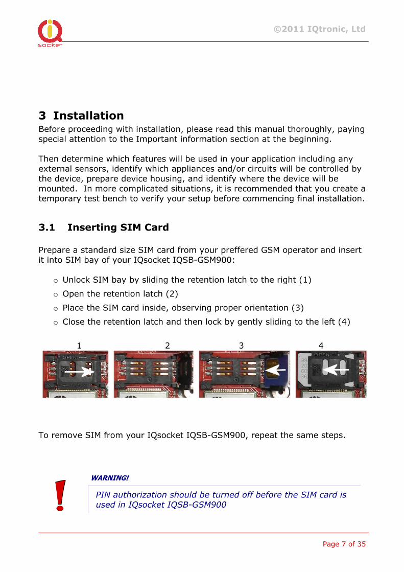
Prepare a standard size SIM card from your preffered GSM operator and insert it into SIM bay of your IQsocket IQSB-GSM900:
o Unlock SIM bay by sliding the retention latch to the right (1)
o Open the retention latch (2)
o Place the SIM card inside, observing proper orientation (3)
o Close the retention latch and then lock by gently sliding to the left (4)
1 2 3 4
To remove SIM from your IQsocket IQSB-GSM900, repeat the same steps.
WARNING!
PIN authorization should be turned off before the SIM card is
used in IQsocket IQSB-GSM900
©2011 IQtronic, Ltd
Page 8 of 35
Authorization can be turned off by inserting the SIM card into a GSM phone and disabling SIM PIN usage using appropriate command usually located in ‘Settings’ phone menu. Now you can remove the SIM card from phone and insert it into your IQsocket IQSB-GSM900.
Note…
It is highly recommended to delete all received SMS messages,
stored on the SIM card before using it in IQsocket IQSB-GSM900
3.2 Wiring the IQsocket IQSB-GSM900
This section describes wiring of the IQsocket IQSB-GSM900.
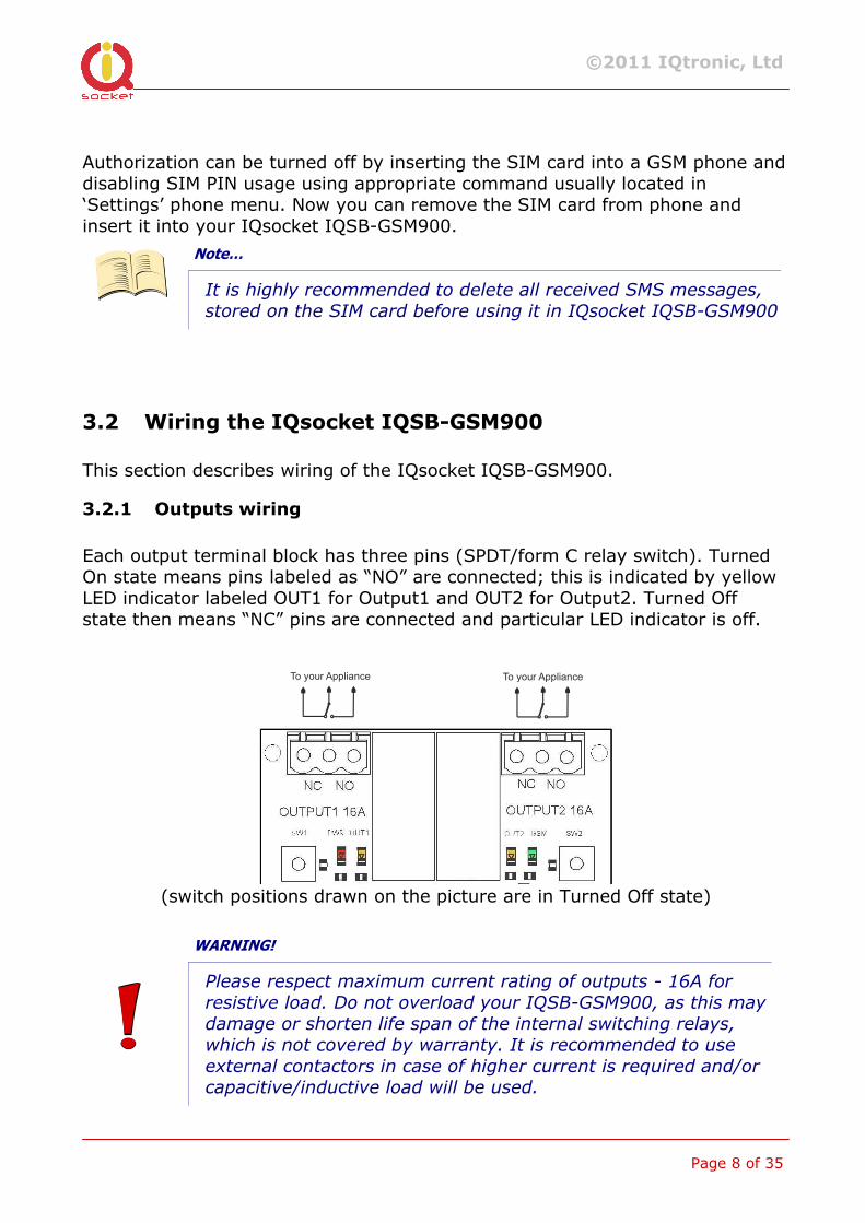
3.2.1 Outputs wiring
Each output terminal block has three pins (SPDT/form C relay switch). Turned On state means pins labeled as “NO” are connected; this is indicated by yellow LED indicator labeled OUT1 for Output1 and OUT2 for Output2. Turned Off state then means “NC” pins are connected and particular LED indicator is off.
To your Appliance To your Appliance
(switch positions drawn on the picture are in Turned Off state)
WARNING!
Please respect maximum current rating of outputs - 16A for
resistive load. Do not overload your IQSB-GSM900, as this may
damage or shorten life span of the internal switching relays,
which is not covered by warranty. It is recommended to use
external contactors in case of higher current is required and/or
capacitive/inductive load will be used.
©2011 IQtronic, Ltd
Page 9 of 35
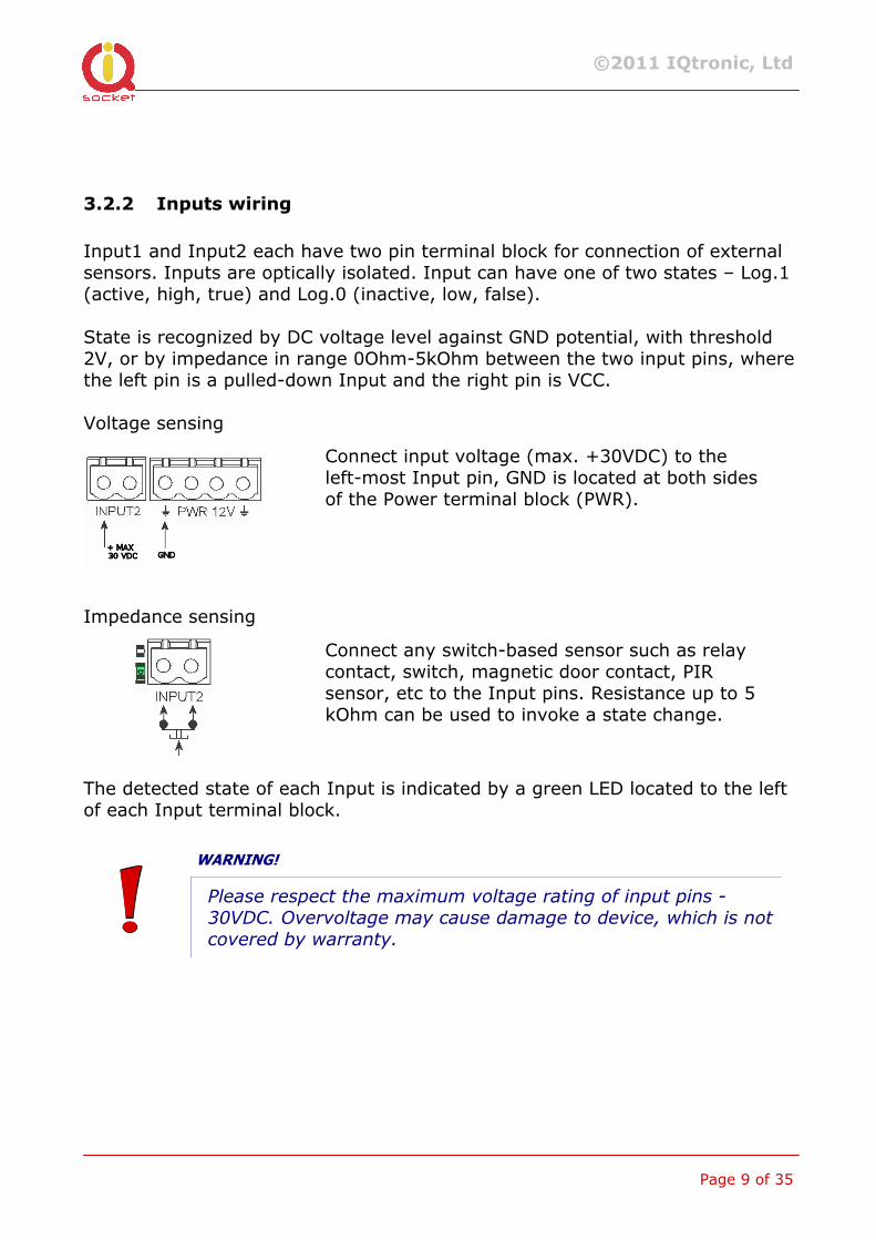
3.2.2 Inputs wiring
Input1 and Input2 each have two pin terminal block for connection of external sensors. Inputs are optically isolated. Input can have one of two states – Log.1 (active, high, true) and Log.0 (inactive, low, false). State is recognized by DC voltage level against GND potential, with threshold 2V, or by impedance in range 0Ohm-5kOhm between the two input pins, where the left pin is a pulled-down Input and the right pin is VCC. Voltage sensing
Impedance sensing The detected state of each Input is indicated by a green LED located to the left of each Input terminal block.
WARNING!
Please respect the maximum voltage rating of input pins -
30VDC. Overvoltage may cause damage to device, which is not
covered by warranty.
Connect input voltage (max. +30VDC) to the left-most Input pin, GND is located at both sides of the Power terminal block (PWR).
Connect any switch-based sensor such as relay contact, switch, magnetic door contact, PIR sensor, etc to the Input pins. Resistance up to 5 kOhm can be used to invoke a state change.
©2011 IQtronic, Ltd
Page 10 of 35
3.2.3 Power supply wiring
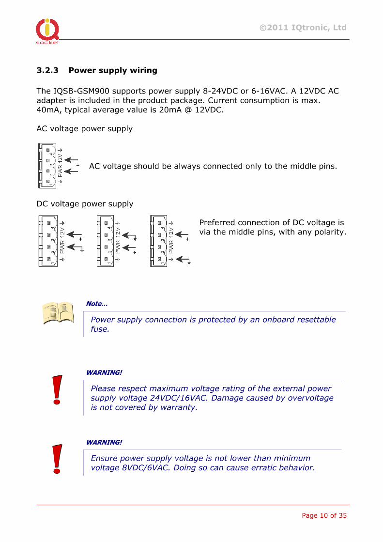
The IQSB-GSM900 supports power supply 8-24VDC or 6-16VAC. A 12VDC AC adapter is included in the product package. Current consumption is max. 40mA, typical average value is 20mA @ 12VDC. AC voltage power supply
AC voltage should be always connected only to the middle pins.
DC voltage power supply
Preferred connection of DC voltage is via the middle pins, with any polarity.
Note…
Power supply connection is protected by an onboard resettable
fuse.
WARNING!
Please respect maximum voltage rating of the external power
supply voltage 24VDC/16VAC. Damage caused by overvoltage
is not covered by warranty.
WARNING!
Ensure power supply voltage is not lower than minimum
voltage 8VDC/6VAC. Doing so can cause erratic behavior.
©2011 IQtronic, Ltd
Page 11 of 35
3.3 Powering IQSB-GSM900 On
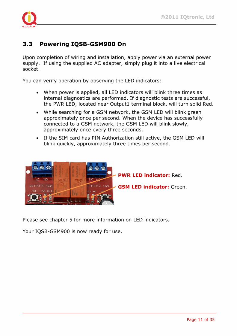
Upon completion of wiring and installation, apply power via an external power supply. If using the supplied AC adapter, simply plug it into a live electrical socket. You can verify operation by observing the LED indicators:
• When power is applied, all LED indicators will blink three times as internal diagnostics are performed. If diagnostic tests are successful, the PWR LED, located near Output1 terminal block, will turn solid Red.
• While searching for a GSM network, the GSM LED will blink green approximately once per second. When the device has successfully connected to a GSM network, the GSM LED will blink slowly, approximately once every three seconds.
• If the SIM card has PIN Authorization still active, the GSM LED will blink quickly, approximately three times per second.
PWR LED indicator: Red.
GSM LED indicator: Green.
Please see chapter 5 for more information on LED indicators. Your IQSB-GSM900 is now ready for use.

©2011 IQtronic, Ltd
Page 12 of 35
4 Managing IQSB-GSM900
This chapter guides you through management commands and features of IQSB-GSM900.
4.1 Managing by SMS
Commands are send in form of SMS messages to call number of SIM card inserted into your device. Messages have following syntax: pinCOMMAND (e.g. 3366STATUS)
o With pre-configured security password by command SMSPIN=3366
COMMAND (e.g. STATUS) o with un-configured security password/SMSPIN
There are two kinds of commands: Control commands (labeled as Ctrl in tables)
o Used to control of the IQSB-GSM900 and can be used at any time. Security settings, such as SMSPIN, permitted callers list, DO apply.
Configuration commands (labeled as Cfg in tables)
o Allows to configure the IQSB-GSM900 parameters and functions. Security settings, such as SMSPIN, permitted callers list, DO NOT apply – instead, as a security measure, configuration commands are accepted only in configuration mode.
o Configuration mode can be activated by using CONFIG command. Notice CONFIG is a Ctrl-class command hence protected by your security settings. Configuration mode is automatically deactivated after 10 minutes since last configuration command has been received.
o When a configuration command has been issued while configuration mode is not active/already expired, error message “Timed Out!” will be replied to the sender. See also chapters 4.7 and 0 for more information about error messages.
Each command is normally confirmed by a response SMS sent back to the command sender number. In case of an error is detected in a command, IQSB-GSM900 will respond with error message to the sender. Sending response and error SMS messages can be disabled. See also chapters 4.7 and 0 for more information about error messages. Case of commands is ignored; STATUS or sTaTUS is the same command.
©2011 IQtronic, Ltd
Page 13 of 35
All incoming SMS messages longer than 30 characters or messages containing space and dot characters are being deleted without any error response. SMS Command Description SMS Response Type
TURNOFF Turn both Output1 and Output2 off TurnedOff Ctrl TURNON Turn both Output1 and Output2 on TurnedOn Ctrl TURNOFF=123 Turn both Output1 and Output2 off
for 123 minutes. Maximum acceptable value is 180 minutes.
TurnedOff 123 min Ctrl
TURNON=123 Turn both Output1 and Output2 on for 123 minutes. Maximum acceptable value is 180 minutes.
TurnedOn 123 min Ctrl
TURNOFF1 Turn the Output1 off TurnedOff1 Ctrl TURNON1 Turn the Output1 on TurnedOn1 Ctrl TURNOFF1=123 Turn the Output1 off for 123 minutes.
Maximum acceptable value is 180 minutes.
TurnedOff 1 123 min Ctrl
TURNON1=123 Turn the Output1 on for 123 minutes. Maximum acceptable value is 180 minutes.
TurnedOn1 123 min Ctrl
TURNOFF2 Turn the Output2 off TurnedOff2 Ctrl TURNON2 Turn the Output2 on TurnedOn2 Ctrl TURNOFF2=123 Turn the Output2 off for 123 minutes.
Maximum acceptable value is 180 minutes.
TurnedOff 2 123 min Ctrl
TURNON2=123 Turn the Output2 on for 123 minutes. Maximum acceptable value is 180 minutes.
TurnedOn2 123 min Ctrl
RESTART Change (negate) state of both Output1 and Output2 for time preconfigured by command RESTARTTIME.
Restarted Ctrl
RESTART1 Change (negate) state of the Output1 for time preconfigured by command RESTARTTIME.
Restarted1 Ctrl
RESTART2 Change (negate) state of the Output2 for time preconfigured by command RESTARTTIME.
Restarted2 Ctrl
STATUS Get status of IQsocket IQSB-GSM900: Outputs and inputs state, temperature and humidity reading, input voltage, time and GSM signal
Output:OFF/OFF, Temp: 25 °C, Humidity 60%, Dpoint 12 °C, Input ON/ON, Voltage 12 V, Time:12/01/21,12:01:25, Signal:76%
Ctrl
If a power failure occurs during TURNON=123/ TURNOFF=123 commands, time of power failure is not included in the countdown, so e.g. you need to run an appliance for a hour issuing TURNON1=60 command, but power is lost after
©2011 IQtronic, Ltd
Page 14 of 35
30minutes and restored back say after 2hours, appliance will be running for half an hour after power is restored back.
4.2 Managing by phone call
The output socket of IQSB-GSM900 can be also controlled by dialing/ringing up the number of its SIM card. Call is for most commands rejected by IQSB-GSM900 so its use is free of charge, with exception for listening sounds using embedded Microphone. Behavior of IQSB-GSM900 to incoming calls must be configured in advance using RING command per following table. SMS Command Description SMS Response Type
RING=NOACTION
No action is performed, call is rejected
RING=NOACTION – OK Cfg
RING=RESTART Change (negate) state of both Output1 and Output2 for time preconfigured by command RESTARTTIME, call is rejected.
RING=RESTART – OK Cfg
RING=RESTART1 Change (negate) state of the Output1 for time preconfigured by command RESTARTTIME, call is rejected.
RING=RESTART1 – OK Cfg
RING=RESTART2 Change (negate) state of the Output2 for time preconfigured by command RESTARTTIME, call is rejected.
RING=RESTART2 – OK Cfg
RING=SWITCH Change (negate) state of both Output1 and Output2, call is rejected.
RING=SWITCH – OK Cfg
RING=SWITCH1 Change (negate) state of the Output1, call is rejected.
RING=SWITCH1 – OK Cfg
RING=SWITCH2 Change (negate) state of the Output2, call is rejected.
RING=SWITCH2 – OK Cfg
RING=MIC Listening of sound in surrounding environment via integrated microphone, call is answered. Call terminated after 1 minute.
RING=MIC – OK Cfg
RING=DTMF Enable DTMF control, see chapter 4.2.1
RING=DTMF – OK Cfg
RING? Get current configuration of RING action, active setting is in () parentheses.
RING=(NOACTION), RESTART, SWITCH, MIC
Cfg
4.2.1 Control using DTMF
IQSB-GSM900 can be controlled via DTMF tones by pressing buttons on your phone after making call to number of its SIM card. DTMF offers increased security and flexibility comparing with control using ringing it up.
©2011 IQtronic, Ltd
Page 15 of 35
In order to use DTMF control, it is necessary to enable it using RING=DTMF command, as is described in previous chapter. Then you can make call to your IQSB-GSM900. Call will be answered and you will hear a short (1s) high tone (like if key 9 pressed) indicating DTMF control is ready. Now, enter the PIN code, which you configured using command SMSPIN (see chapter 4.6), and confirm it by pressing # key. In case you entered a wrong PIN, you will hear three times low tone beep (like if key * pressed) and call will be ended. When a valid PIN has been entered, you will hear the short (1s) high tone (like if key 9 pressed) again, indicating PIN has been accepted. Now, you can enter your command manually using keypad on your phone or command pre-configured by DTMFCONTROL will be immediately executed and you can terminate the call. Supported manual DTMF commands
10# - Output 1 state 0 – to turn Output1 to OFF state 11# - Output 1 state 1 – to turn Output1 to ON state 20# - Output 2 state 0 – to turn Output2 to OFF state 21# - Output 2 state 1 – to turn Output2 to ON state 30# - Turn on microphone for tapping 31# - Turn off microphone for tapping After you enter particular command code, e.g.10 and confirm it by pressing #, you will hear either short high beep in case of success, or three times low beep when you entered a wrong/invalid command. Now you can terminate the call. Pre-configured DTMF commands
SMS Command Description SMS Response Type
DTMFCONTROL= MANUAL
Waiting for manual command entered through phone keypad
DTMFCONTROL= MANUAL – OK
Cfg
DTMFCONTROL =RESTART
Change (negate) state of both Output1 and Output2 for time preconfigured by command RESTARTTIME
DTMFCONTROL =RESTART – OK
Cfg
DTMFCONTROL =RESTART1
Change (negate) state of the Output1 for time preconfigured by command RESTARTTIME
DTMFCONTROL =RESTART1 – OK
Cfg
DTMFCONTROL =RESTART2
Change (negate) state of the Output2 for time preconfigured by command RESTARTTIME
DTMFCONTROL =RESTART2 – OK
Cfg
DTMFCONTROL Change (negate) state of both DTMFCONTROL =SWITCH Cfg
©2011 IQtronic, Ltd
Page 16 of 35
=SWITCH Output1 and Output2 – OK DTMFCONTROL =SWITCH1
Change (negate) state of the Output1 DTMFCONTROL =SWITCH1 – OK
Cfg
DTMFCONTROL =SWITCH2
Change (negate) state of the Output2 DTMFCONTROL =SWITCH2 – OK
Cfg
DTMFCONTROL =MIC
Listening of sound in surrounding environment via integrated microphone
DTMFCONTROL =MIC – OK
Cfg
DTMFCONTROL? Get current configuration of DTMFCONTROL, active setting is in () parentheses.
DTMFCONTROL =(MANUAL), RESTART, RESTART1, RESTART2, SWITCH, SWITCH1, SWITCH2, MIC
Cfg
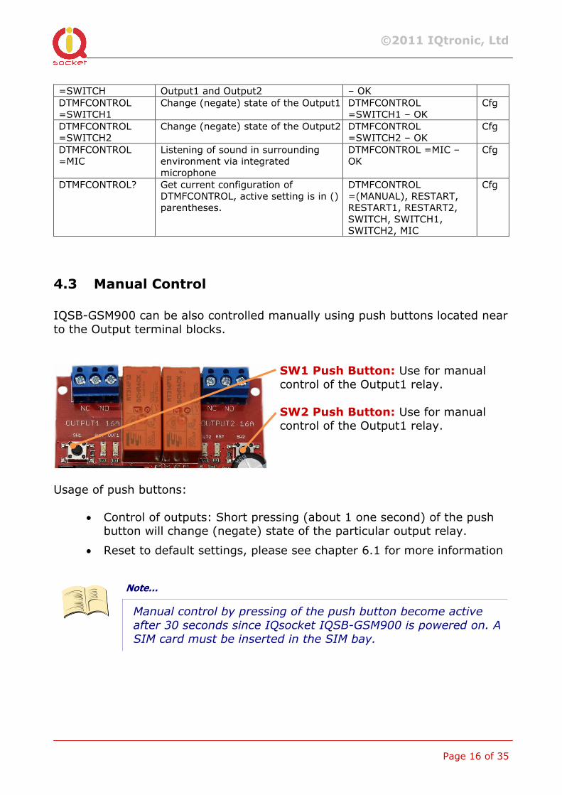
4.3 Manual Control
IQSB-GSM900 can be also controlled manually using push buttons located near to the Output terminal blocks.
SW1 Push Button: Use for manual control of the Output1 relay.
SW2 Push Button: Use for manual control of the Output1 relay.
Usage of push buttons:
• Control of outputs: Short pressing (about 1 one second) of the push button will change (negate) state of the particular output relay.
• Reset to default settings, please see chapter 6.1 for more information
Note…
Manual control by pressing of the push button become active
after 30 seconds since IQsocket IQSB-GSM900 is powered on. A
SIM card must be inserted in the SIM bay.
©2011 IQtronic, Ltd
Page 17 of 35
4.4 Timing setup
Some of the IQSB-GSM900 features use a predefined time intervals, which can be changed by SMS configuration commands.
4.4.1 RESTARTTTIME
Following table summarizes settings of time interval of RESTART command: SMS Command Description SMS Response Type
RESTARTTIME=XX Configures time of RESTART command. Range is 1 to 180 seconds.
RESTARTTIME=XX – OK Cfg
RESTARTTIME? Get current configuration of RESTARTTIME parameter.
RESTARTTIME=10 seconds Cfg
4.4.2 RINGONTIME
Following table summarizes settings of time interval how long will be device keeping ringing up the target telephone number (defined by ALARMNUMBER) in case of generating alarm alert or invoked by RINGON command: SMS Command Description SMS Response Type
RINGONTIME=XX Configures time of RESTART command. Range is 1 to 180 seconds.
RINGONTIME=XX – OK Cfg
RINGONTIME? Get current configuration of RESTARTTIME parameter.
RINGONTIME=10 seconds Cfg
Note…
A call initiated by the IQSB-GSM900, such as alarm alert can be
either ignored (ringing will end after passing of RINGONTIME), rejected, or answered to activate tapping function using on-
board microphone.
©2011 IQtronic, Ltd
Page 18 of 35
4.5 Date/Time setup
There are three ways of date/time setup:
• Automatic setup of time from the GSM network, when particular operator and SIM card support such feature.
• Manual setup based on time stamp of incoming SMS message
• Manual setup using DATE= command. Enter target time in following format: DATE=yy/mm/dd,hh:mm:ss+zz where zz is Time zone, with either + or - sign.
SMS Command Description SMS Response Type
DATE Date/time is set from timestamp of incoming SMS message.
DATE yy/mm/dd,hh:mm:ss+zz – OK
Cfg
DATE=yy/mm/dd,hh:mm:ss+zz
Set Date/time manually. DATE=yy/mm/dd,hh:mm:ss+zz – OK
Cfg
DATE? Get current settings of Date/time. DATE yy/mm/dd,hh:mm:ss+zz – OK
Cfg
Note…
If your GSM network and SIM card supports obtaining of current
time from the network, it is not necessary to take any action in
order to setup time – it will be done automatically during each
IQSB-GSM900 startup.
4.6 Security features
IQsocket IQSB-GSM900 is equipped with advanced authorization features to avoid controlling by unauthorized users. The security features include:
• Allowing control only from authorized phone numbers • Authentication of each SMS command by PIN code (SMSPIN)
Both features can be used simultaneously. In case of using authorized numbers list, device will ignore all SMS messages and calls received from numbers not included in the permitted phone numbers list. If this security feature is not enabled, device can be controlled by anyone
©2011 IQtronic, Ltd
Page 19 of 35
who knows number associated with inserted SIM card (and SMS pin in case PIN code protection is also active). IQsocket IQSB-GSM900 allows to define up to 20 permitted phone numbers, each containing up to 15 numerals. In case of using SMSPIN, right before each SMS command is placed PIN code without any space or special character, as shown here: pinCOMMAND (e.g. 3366STATUS) Command will be accepted only when entered PIN code matches with the code predefined by SMSPIN command.
Note…
Pin code (SMSPIN) is having no relation with SIM card PIN code.
It is just a password called SMSPIN and used by IQsocket IQSB-
GSM900 for SMS message authentication, having the same
structure as standard PIN = 4 numerals.
Security settings can be configured and viewed simply by following commands.
SMS Command Description SMS Response Type
SECNUMBER=NO Security using permitted phone numbers list is turned off/inactive.
SECNUMBER=NO - OK Cfg
SECNUMBER=YES Security using permitted phone numbers list is turned on/active.
SECNUMBER=YES - OK Cfg
SECNUMBER? Get current configuration of SECNUMBER parameter.
SECNUMBER=(NO),YES Cfg
SECNUMBER+ 420123456788
Add new number to security list. SECNUMBER+420123456788- OK
Cfg
SECNUMBER-420123456788
Delete specific number from permitted phone numbers list.
SECNUMBER-420123456788- OK
Cfg
SECNUMBER-ALL Delete all numbers from permitted phone numbers list.
SECNUMBER-ALL - OK Cfg
SECNUMBER=LIST Get dump of permitted phone numbers list.
LIST 420123456788,421903111222,421235678235 Or LIST - NO NUMBER!
Cfg
SMSPIN=1234 Configuration of SMS
password/SMSPIN. SMSPIN=1234 – OK Cfg
SMSPIN=NOPIN Using of password/SMSPIN is deactivated.
SMSPIN=NOPIN – OK Cfg
SMSPIN? Get configuration of SMSPIN parameter.
SMSPIN=(NOPIN), 1234 Cfg
©2011 IQtronic, Ltd
Page 20 of 35
Permitted phone numbers list accept up to 20 numbers, must contain only numbers in international format, without spaces or other characters, max. 15 numerals long: Example: SECNUMBER+421265440655 means add number +421-2-65440655 Example: SECNUMBER-421265440655 means delete number +421-2-65440655. 421 is country code in this example and 2 is area code.
4.7 Response messages settings
When you communicate with your IQsocket IQSB-GSM900, it is important to make you sure if command was understood and executed successfully. For this purpose we implemented response messages, confirming each command or informing you when an error is detected. In case of SMS commands, you will be notified by back SMS response message. If you manage your IQsocket IQSB-GSM900 by phone call, your command will be confirmed by back phone call to your phone number. Note it is not supposed you will answer such back call, you can simply reject it. Configuration commands of response messages settings are summarized in following table: SMS Command Description SMS Response Type
SMSCONFIRM=YES SMS confirmation is enabled/active for all SMS commands
SMSCONFIRM=YES - OK Cfg
SMSCONFIRM=NO SMS confirmation is disabled/inactive for all SMS commands
SMSCONFIRM=NO - OK Cfg
SMSCONFIRM? Get configuration of SMSCONFIRM parameter, active setting is in () parentheses.
SMSCONFIRM=NO,(YES)
Cfg
SMSCONFIRMUNAUTH=YES
SMS confirmation for SMS control commands is active also for unauthorized numbers.
SMSCONFIRMUNAUTH=YES -
OK
Cfg
SMSCONFIRMUNAUTH=NO
SMS confirmation for SMS control commands is not active for unauthorized numbers
SMSCONFIRMUNAUTH=NO -
OK
Cfg
RINGCONFIRM=YES Phone call confirmation is turned on for all commands. Hang off after 10 seconds
RINGCONFIRM=YES – OK Cfg
RINGCONFIRM=NO Phone call confirmation is turned off for all commands
RINGCONFIRM=NO – OK Cfg
RINGCONFIRM? Get configuration of RINGCONFIRM parameter, active setting is in () parentheses.
RINGCONFIRM=(OFF),ON Cfg
ERRORREPLY=YES Sending error SMS messages is enabled/active
ERRORREPLY=YES- OK Cfg
ERRORREPLY=NO Sending error SMS messages is disabled/inactive
ERRORREPLY=NO- OK Cfg
©2011 IQtronic, Ltd
Page 21 of 35
ERRORREPLY? Get configuration of ERRORREPLY parameter, active setting is in () parentheses.
ERRORREPLY=NO,(YES) Cfg
Note…
When RINGCONFIRM=YES command is used, confirmation back
calls are only realized for SIM cards with active CLIP service.
4.8 Scheduler feature
Your IQsocket IQSB-GSM900 is equipped with a scheduler, allowing to control outputs and to get status message, based on time and day of week. Up to 20 scheduled tasks are supported. Following table summarizes usage of SCHEDULER command. SMS Command Description SMS Response Type
SCHEDULER+hh:mm,DOW,ACTION
Insert scheduler record to execute particular ACTION at time hh:mm every day of week DOW.
SCHEDULER+hh:mm, DOW,ACTION - OK
Ctrl
SCHEDULER-hh:mm Remove scheduler record for particular time hh:mm
SCHEDULER-hh:mm - OK Ctrl
SCHEDULER? Get list of all scheduler records. hh:mm,DOW,ACTION
Ctrl
Where: hh:mm denotes hour and minute of time in 24h format. DOW denotes day of week. Days of week numbers are recognized as follows: 1- Monday, 2-Tuesday, 3-Wednesday, 4 Thursday, 5-Friday, 6-Saturday, 7- Sunday
If “*” symbol is inserted, action will be executed daily. If number of day within week is inserted, action will be executed only in the particular day of week. Possible actions are:
• ON1 for turning the Output1 on (same as TURNON1 command)
• ON2 for turning the Output1 on (same as TURNON2 command)
• OFF1 for turning the Output1 off (same as TURNOFF1 command)
• OFF2 for turning the Output2 off (same as TURNOFF2 command)
• RES1 for restarting the Output1 (same as RESTART1 command)
• RES2 for restarting the Output2 (same as RESTART2 command)
©2011 IQtronic, Ltd
Page 22 of 35
• INF, to send STATUS message by SMS to number preconfigured by the ALARMNUMBER command (e.g. ALARMNUMBER+421903123456, see chapter 4.10.1)
Example of SCHEDULER? command output (four actions were recorded):
o 11:00,*,ON 1 Turn on Output1 every day at 11:00 o 14:30,*,OFF1 Turn off Output1 every day at 14:30 o 01:30,1,RES1 Restart Output1 every Monday at 01:30 o 19:00,5,INF Send Status SMS every Friday at 19:00
Note…
In order to use INF action – sending status message, it is
necessary to configure target numbers first using
ALARMNUMBER command, see chapter 4.10.1 for more
information.
Note…
Actions of SCHEDULER command are executed only on particular
time, it is still possible to control of outputs by SMS or manually
in other time intervals.
4.9 Counters
Seven independent counters increments their status upon change on IQSB-GSM900 inputs and outputs. SMS Command Description SMS Response Type
COUNTER1? Get status of Counter1, increments on change of Output1
COUNTER1=0 Ctrl
COUNTER2? Get status of Counter2, increments on change of Output2
COUNTER2=0 Ctrl
COUNTER3? Get status of Counter3, increments on change of Input1
COUNTER3=0 Ctrl
COUNTER4? Get status of Counter4, increments on change of Input2
COUNTER4=0 Ctrl
COUNTER5? Get status of Counter5, increments on pressing of Push Button SW1
COUNTER5=0 Ctrl
COUNTER6? Get status of Counter6, increments on pressing of Push Button SW2
COUNTER6=0 Ctrl
COUNTER7? Get status of Counter7, increments on loosing registration into GSM network
COUNTER7=0 Ctrl
©2011 IQtronic, Ltd
Page 23 of 35
COUNTERX? Get status of all counters COUNTER=0,0,0,0,0,0,0 Ctrl CLEARCOUNTER1 Clear status of counter 1 (2-7) CLEARCOUNTER1- OK Ctrl CLEARCOUNTERALL Clear status of all counters CLEARCOUNTERALL- OK Ctrl
Counter1 and Counter2 is incremented by 1 after commands RESTART, TURNOFF, TURNON. Highest possible status of a counter is 65535.
4.10 Alarms
IQSB-GSM900 supports following independent alarm sources, sorted by priority:
• Alarm invoked by Input1 (highest priority)
• Alarm invoked by Input2
• Temperature alarm
• Humidity alarm
• Power supply voltage drop alarm
• INF action of the SCHEDULER command
• Change of GSM BTS alarm (lowest priority)
An alarm can generate alert by sending SMS to or by calling of (only in case alarms invoked by inputs) up to five (5) predefined phone numbers.
Note…
In order to use SMS alarm alerts, it is necessary to configure
target numbers by ALARMNUMBER command, see chapter
4.10.1 for more information.
4.10.1 Defining phone numbers for SMS and ringing up alerts
Phone numbers must be entered in international format, see following table. SMS Command Description SMS Response Type
ALARMNUMBER+ 420123456789
Add a new number into list for alarm alerts using SMS message and call back.
ALARMNUMBER+420123456789 - OK
Cfg
ALARMNUMBER- Remove a number from list for ALARMNUMBER- Cfg
©2011 IQtronic, Ltd
Page 24 of 35
420123456789 alarm alerts using SMS message and call back.
420123456789 - OK
ALARMNUMBER-ALL Remove all numbers from list for alarm alerts using SMS message and call back.
ALARMNUMBER-ALL- OK Cfg
ALARMNUMBER=LIST Get list of phone numbers for alarm alerts using SMS message and call back.
LIST 420123456789 Cfg
When generating alerts, numbers in list are processed per their order – the first number first, the last number as last.
4.10.2 Alarm invoked by Inputs
Alarm invoked by Inputs is having highest processing priority. See chapter 3.2.2 for information on wiring and recognizing of input states. For increased flexibility, evaluation of input alarm depends on user-defined trigger time: Following table summarizes settings of trigger time interval for evaluation of input state used by ALARM command: SMS Command Description SMS Response Type
TRIGGERTIME1=XX Configures trigger time in milliseconds for evaluation of Input1 state. Range is 300 to 60 000 milliseconds.
TRIGGERTIME1=XX – OK Cfg
TRIGGERTIME1? Get current configuration of TRIGGERTIME1 parameter.
TRIGGERTIME1=300 miliseconds
Cfg
TRIGGERTIME2=XX Configures trigger time in milliseconds for evaluation of Input1 state. Range is 300 to 60 000 milliseconds.
TRIGGERTIME2=XX – OK Cfg
TRIGGERTIME2? Get current configuration of TRIGGERTIME1 parameter.
TRIGGERTIME2=300 miliseconds
Cfg
Input alarm can be activated by:
o change of the input state, or o by existence of one from possible states Log.0 (inactive, false, L-low, no voltage appears at the left input pin, left and right pin not connected) or Log.1 (active, true, H-high, voltage higher than threshold appears at the left input pin, left and right input pins short connected).
This behavior is configured by command INPUTTYPE, settings do apply for both Input1 and Input2: SMS Command Description SMS Response Type
INPUTTYPE=CHANGE Alarm is activated at every change INPUTTYPE=CHANGE - OK Cfg
©2011 IQtronic, Ltd
Page 25 of 35
of input state INPUTTYPE=HIGH Send alert SMS every time when
remaining battery charge falls below defined threshold 50%.
INPUTTYPE=HIGH- OK Cfg
INPUTTYPE=LOW Disable sending remaining battery charge alerts
INPUTTYPE=LOW- OK Cfg
INPUTTYPE? Get configuration of INPUTTYPE, active setting is in () parentheses.
INPUTTYPE =(CHANGE), HIGH, LOW
Cfg
It is also possible to define time delay between consecutive alarm activations by using NEXTTESTTIME command: SMS Command Description SMS Response Type
NEXTTESTTIME1=10 Next activation of Input1 alarm is possible after 10minutes.
NEXTTESTTIME1=10 - OK Cfg
NEXTTESTTIME1? Get current settings of Input1 time delay
NEXTTESTTIME1=10 minutes
Cfg
NEXTTESTTIME2=10 Next activation of Input2 alarm is possible after 10minutes.
NEXTTESTTIME2=10 - OK Cfg
NEXTTESTTIME2? Get current settings of Input2 time delay
NEXTTESTTIME2=10 minutes
Cfg
If an input alarm state occurs sooner than is NEXTTESTTIME value, alarm will be activated after expiring of NEXTTESTTIME time. Setting NEXTTESTTIME to zero (0) value deactivated this option. Alarm detection at Input1 and Input2 can be activated by the INPUTALARM command: SMS Command Description SMS Response Type
INPUTALARM=NOALARM No input alarm is active INPUTALARM=NOALARM- OK
Cfg
INPUTALARM=ACTIVE1 Input1 alarm is active INPUTALARM=ACTIVE1- OK
Cfg
INPUTALARM=ACTIVE2 Input2 alarm is active INPUTALARM=ACTIVE2- OK
Cfg
INPUTALARM=ACTIVEBOTH Both Input1 and Input2 alarm are active
INPUTALARM=ACTIVEBOTH- OK
Cfg
INPUTALARM? Get configuration of INPUTALARM, active setting is in () parentheses.
INPUTALARM=(NOALARM, ACTIVE1, ACTIVE2, ACTIVEBOTH
Cfg
Selecting type of input alarm alert: SMS Command Description SMS Response Type
ALARM=RING Type of alarm alert is ringing up defined telephone number(s)
ALARM=RING- OK Cfg
ALARM=SMS Type of alarm alert is sending SMS to defined telephone number(s)
ALARM=SMS- OK Cfg
ALARM? Get configuration of ALARM, ALARM =(SMS), RING Cfg
©2011 IQtronic, Ltd
Page 26 of 35
active setting is in () parentheses.
Note…
Alert by ringing up/calling target telephone numbers is
supported only for alarms invoked by inputs.
Defining custom text in alert SMS – each text can be up to 20characters long: SMS Command Description SMS Response Type
ALIASINPUT1=disconnected,connected
Alert text sent in case of Input1 Alarm is: disconnected, resp. connected
ALIASINPUT1=disconnected,connected - OK
Cfg
ALIASINPUT1? Get current settings of Input1 alert alias
ALIASINPUT1=low,high Cfg
ALIASINPUT2=disconnected,connected
Alert text sent in case of Input2 Alarm is: disconnected, resp. connected
ALIASINPUT2=disconnected,connected - OK
Cfg
ALIASINPUT2? Get current settings of Input2 alert alias
ALIASINPUT2=low,high Cfg
4.10.3 Temperature alarm
IQSB-GSM900 allows watching user-defined temperature interval in range from 0 to 50°C using on-board temperature sensor. It is possible to define when will be alarm generated: when temperature is reaching minimum, maximum or both defined minimum and maximum levels. SMS Command Description SMS Response Type
TEMPMIN=20 Lower temperature limit in °C TEMPMIN=20- OK Ctrl TEMPMAX=30 Upper temperature limit in °C TEMPMAX=30- OK Ctrl TEMPALARM=NOALARM Temperature alarm is disabled TEMPALARM=NOALARM- OK Ctrl TEMPALARM=MIN Temperature alarm is active
for lower limit TEMPALARM=MIN- OK Ctrl
TEMPALARM=MAX Temperature alarm is active for upper limit
TEMPALARM=MAX- OK Ctrl
TEMPALARM=MIX Temperature alarm is active for both lower and upper limit
TEMPALARM=MIX- OK Ctrl
TEMPALARM? Get configuration of TEMPALARM, active setting is in () parentheses.
TEMPALARM=(MIX), MIN, MAX
Ctrl
©2011 IQtronic, Ltd
Page 27 of 35
4.10.4 Humidity alarm
IQSB-GSM900 allows watching user-defined interval of relative humidity in range from 0 to 100% using on-board relative humidity sensor. It is possible to define when will be alarm generated: when humidity is reaching minimum, maximum or both defined minimum and maximum levels. SMS Command Description SMS Response Type
HUMMIN=50 Lower rel.humidity limit in % HUMMIN=50- OK Ctrl HUMMAX=80 Upper rel.humidity limit in % HUMMAX=80- OK Ctrl HUMALARM=NOALARM Humidity alarm is disabled HUMALARM =NOALARM- OK Ctrl HUMALARM=MIN Humidity alarm is active for
lower limit HUMALARM =MIN- OK Ctrl
HUMALARM=MAX Humidity alarm is active for upper limit
HUMALARM =MAX- OK Ctrl
HUMALARM=MIX Humidity alarm is active for both lower and upper limit
HUMALARM =MIX- OK Ctrl
HUMALARM? Get configuration of HUMALARM, active setting is in () parentheses.
HUMALARM =(MIX), MIN, MAX
Ctrl
4.10.5 Power supply voltage drop alarm
IQSB-GSM900 can send you an SMS alert to inform you when there is a drop of power supply voltage bellow the defined threshold. Hysteresis is set to 2V. If power supply voltage drops below the defined threshold, an SMS alert with text “Alarm voltage XX V” is sent to numbers defined by ALARMNUMBER command. SMS Command Description SMS Response Type
PWRALARM=0 Disable power supply voltage drop alarm.
PWRALARM=0- OK Cfg
PWRALARM=16 Activate power supply voltage drop alarm with given threshold (max. supported threshold value is 16V).
PWRALARM=16- OK Cfg
PWRALARM? Get current settings of PWRALARM PWRALARM =16 Cfg
©2011 IQtronic, Ltd
Page 28 of 35
4.10.6 Change of GSM BTS alarm
IQSB-GSM900 can send you an SMS alert to inform you when there is a change of GSM BTS cell, to which it is connected: SMS Command Description SMS Response Type
ALARMCELLON Activate GSM BTS change alarm. ALARMCELLON- OK Ctrl ALARMCELLOFF Disable GSM BTS change alarm. ALARMCELLOFF- OK Ctrl
4.10.7 Disabling all alarms
In case you need to quickly disable all alarms e.g. in case of emergency or misconfiguration, you can do it by issuing single command ALLALARMSOFF. Please note all alarms will be disabled permanently, you need to enable each wanted alarm again one by one. SMS Command Description SMS Response Type
ALLALARMSOFF All alarms are permanently disabled ALLALARMSOFF- OK Ctrl
4.11 Using microphone
Your IQSB-GSM900 is equipped with a highly sensitive microphone, which can be used to monitor sound through any phone. Sensitivity is typically sufficient to recognize voices within even larger room where is IQSB-GSM900 installed; it depends on device orientation and placement and also on background noise. Microphone is activated by either answering a call from your IQSB-GSM900, such as when an input alarm has been detected, while alarm alert is set to ring using ALARM=RING command (see chapter 4.10); or by calling the number of your IQSB-GSM900, while RING=MIC setting is preconfigured (see chapter 4.2 ) or DTMFCONTROL is set to MIC (see chapter 4.2.1)
WARNING!
Please respect privacy and local law regarding to tapping,
especially when monitored subjects are not informed about it.
It is your sole responsibility how you will use it.
©2011 IQtronic, Ltd
Page 29 of 35
4.12 Various other settings
SMS Command Description SMS Response Type
CONFIG Activate configuration mode. Automatically deactivated 10minutes after last configuration command that have been received.
CONFIG, OK Ctrl
OUTPUT=REMEMBER When powered on/power restored, state of both Output1 and Output2 will be returned to the same state as it was at time of disconnecting power /power lost.
OUTPUT=REMEMBER- OK Cfg
OUTPUT=NO When powered on/power restored, state of both Output1 and Output2 be set to have connected NO pins, regardless of state that was at time of disconnecting power /power lost.
OUTPUT=NO- OK Cfg
OUTPUT=NC When powered on/power restored, state of both Output1 and Output2 be set to have connected NC pins, regardless of state that was at time of disconnecting power /power lost.
OUTPUT=NC- OK Cfg
OUTPUT? Get configuration of OUTPUT parameter, active setting is in () parentheses.
OUTPUT =(REMEMBER),NC,NO
Cfg
RINGON A call-back to the sender’s number will be made. Useful to keep-alive of credit in prepaid SIM cards.
Ctrl
TEMPUNIT=F Changes temperature units to Fahrenheit
TEMPUNIT=F- OK Cfg
TEMPUNIT? Get current temperature unit, active setting is in () parentheses.
TEMPUNIT=(C),F Cfg
ADJUSTTEMP=6 Set calibration constant of temperature to compensate heat produced by the device, number will be subtracted from sensor reading
ADJUSTTEMP=6 - OK Cfg
ADJUSTTEMP? Get current value of calibration constant
ADJUSTTEMP=6 Cfg
HELP Get list of all commands as help Ctrl LANG=EN Switch language version LANG=EN- OK Cfg LANG? Get current language version, active
setting is in () parentheses. LANG=(EN), CZ Cfg
VERSION Get firmware version Ver. 2.0.1 (c)2011 IQtronic Ltd.
Ctrl
©2011 IQtronic, Ltd
Page 30 of 35
Note…
Please note firmware of IQsocket IQSB-GSM900 can be
upgraded only by sending unit back to the factory or to an
authorized service center.
Note…
In case you unintentionally changed language to CZ, you can
switch it back to EN using commands KONFIG and LANG=EN
4.13 Error messages
Error messages are being sent only when sending response messages is permitted (see also ERRORREPLY command). SMS response Description
Error! Incorrect control or configuration command; or wrong SMSPIN. Not allowed! In case of permitted phone numbers list is active but used number is not
included in it. Timeout! 10 minutes interval of configuration mode has expired. In order to
continue using configuration commands, please enter CONFIG command again.
Full memory! Memory for storing permitted phone numbers is full. No record When trying to delete non-existing records, e.g. scheduled tasks
©2011 IQtronic, Ltd
Page 31 of 35
5 Indicators The IQsocket IQSB-GSM900 is equipped with six LED indicators: PWR
LIGHTS RED Input power is OK; normal operation BLINKS RED 2 x PER SECOND SIM is not correctly inserted or missing or is bad GSM BLINKS GREEN, EACH 3 SECONDS Logged to GSM network, normal operation BLINKING GREEN EACH SECOND Not logged to GSM network yet, searching LIGHTS GREEN 2 x PER SECOND SIM card have active PIN protection, use a GSM
phone to disable it. OUT1, OUT2 NOT ACTIVE Particular output has connected NC pins LIGHTS YELLOW Particular output has connected NO pins BLINKS YELLOW Hardware error/failure Input1, Input2 NOT ACTIVE Particular input is in Log.0/low/inactive state LIGHTS GREEEN Particular input is in Log.1/high/active state
©2011 IQtronic, Ltd
Page 32 of 35
6 Factory default settings Each device come from factory preconfigured with factory default values. Device can be anytime returned back to these default values by using reset to factory defaults procedure.
6.1 Reset to factory default procedure
Reset is done by pushing both pushbuttons SW1, SW2 located near outputs terminal blocks. In order to restore factory default configuration, push both SW1 and SW2 for at least 5 seconds and then release. All LED indicators should start blinking for next 10 seconds. Please press shortly both push buttons once again within these 10 seconds to confirm reset to factory default procedure. After this step is your device in original factory configuration.
WARNING!
Please BE CAREFULL! This step will erase all settings of your
IQsocket IQSB-GSM900 except language settings.
6.2 Factory default settings
Parameter Default setting Parameter Default setting
OUTPUT1 NC INPUTALARM NOALARM OUTPUT2 NC ALARM SMS SMSPIN NOPIN ALIASINPUT1 LOG0,LOG1 RESTARTTIME 10 ALIASINPUT2 LOG0,LOG1 RING NOACTION TEMPMIN 20 SECNUMBER NO TEMPMAX 30 SMSCONFIRM YES TEMPALARM NOALARM RINGCONFIRM NO HUMMIN 50 ERRORREPLY YES HUMMAX 80 SMSCONFIRMUNAUTH YES HUMALARM NOALARM TRIGGERTIME1 300 PWRALARM 0 TRIGGERTIME1 300 RINGONTIME 30 INPUTTYPE CHANGE OUTPUT REMEMBER NEXTTESTTIME1 0 TEMPUNIT C NEXTTESTTIME2 0 ADJUSTTEMP 6 DTMFCONTROL MANUAL
©2011 IQtronic, Ltd
Page 33 of 35
7 Technical specification Model
Power supply 8-24VDC, 6-16VAC
Consumption 40mA @ 12VDC
Output switch 2x Bistable relay SPDT/FormC,
230VAC, 16A max (resistive load)
Inputs 2x binary, optically isolated inputs, 30VDC max
2V detection threshold, pulled down
Onboard sensors Temperature -10 to +100°C (+/- 1°C)
Relative humidity 0 to 100% (+/- 3%)
(usable range limited by board operating environment range)
Management Via SMS messages
Security PIN code protected commands
Permitted phone numbers list
GSM EGSM900, GSM850 Class4 (2W)
DCS1800, PCS1900 Class1 (1W)
SIM card Plug-in 3V
External 2dBi antenna via SMA-F connector, included in package
Indicators 6x LED indicator
Features Appliance control over SMS, by call or manually Temperature and humidity sensors Remote restart of appliances Scheduler Alarms Counters Monitoring of sound using integrated microphone
Dimensions 100x70x30mm
Weight 0.1kg netto
Operating temperature 0 to +50 ˚C
Operating humidity Max. 80%, non-condensing
Compliance CE, FCC
©2011 IQtronic, Ltd
Page 34 of 35
7.1 Operation, maintenance and safety recommendations
• Do not modify product in any way and do not operate product modified
any way. Warranty is void when product was disassembled or modified in any way.
• Product can be operated only indoor office/house environment. Do not expose it to humid, wet nor chemically aggressive environment.
• Product is not designed for industrial operation with aggressive environment.
• Before use, please check, if mobile phones can be used in the area. In not, please don’t put product into operation, it can have negative influence to other electronic systems.
• Don’t expose product to vibrations, shaking or fall downs to avoid product damage.
• When use sound monitoring for taping purposes, ensure you have prior permission to do it from affected people.
• Load current 16A is valid for resistive load. If you need to switch an non-resistive or higher current load, use an external contactor rated for target load among the product. Switching a non-resistive load or higher than nominal rating currents can cause permanent damage of switching elements, which is not covered by warranty.
• Before using a SIM card, ensure all received SMS messages stored on the card are deleted.
• Product is not a toy for children, SIM card represents a small part that can be easily ingested.
• WARNING: This product is not designed for use in, and should not be used for, medical applications.
©2011 IQtronic, Ltd
Page 35 of 35
8 Ordering and accessories IQsocket product family uses following ordering code system: IQSx-y-z Example: IQSB-GSM900
Product family: W=WALL | R=RACK | D=DIN | B=Board Product model: GSM | GSML | GSMRF | IP | RS232 | HDO | IPGSM Electric standard of plug/socket: F=Schuko | E=French, B=British, N=USA
Ordering code Code Description IQSB-GSM900-TH with on board temperature and humidity sensors IQSB-GSM900 cost-down version without temp/humidity sensors Optional accessories Code Description ADAPT-12V-EU AC power supply adapter, 12V/500mA, EU version ADAPT-12V-US AC power supply adapter, 12V/500mA, US version ADAPT-12V-UK AC power supply adapter, 12V/500mA, UK version ANTGSM External 2dBi GSM antenna, SMA (included in std. package) ANTGSM-2M External 2dBi GSM antenna, 2m cable, SMA