Embed Size (px)
Citation preview

December 2012 Doc ID 023257 Rev 1 1/14
UM1548User manual
IR remote trasmitter STEVAL-IHM037V1
IntroductionThe IR transmitter solution features three buttons which can be used to transmit three unique IR commands for various IR remote control applications. It is a direct implementation of the AN2957 application note, ‘Implementing an RC5 infrared transmitter using the IR timer modulator of the STM8L101xx microcontroller’. An STM8L101xx low power MCU is used to implement this design. The existing firmware, which is supplied with the application note, was modified slightly to accommodate for the three keys present in the design which are used to control speed-up, speed-down and power-on/off toggle operations. The circuit runs on a CR2032 coin cell battery and is designed to fit into a small key fob type enclosure.
Figure 1. IR remote transmitter STEVAL-IHM037V1
This document explains the different parts and functions of the IR remote transmitter.
www.st.com

Contents UM1548
2/14 Doc ID 023257 Rev 1
Contents
1 Getting started . . . . . . . . . . . . . . . . . . . . . . . . . . . . . . . . . . . . . . . . . . . . . . 4
1.1 Package . . . . . . . . . . . . . . . . . . . . . . . . . . . . . . . . . . . . . . . . . . . . . . . . . . . 4
1.2 Initial setup . . . . . . . . . . . . . . . . . . . . . . . . . . . . . . . . . . . . . . . . . . . . . . . . . 4
2 System overview . . . . . . . . . . . . . . . . . . . . . . . . . . . . . . . . . . . . . . . . . . . . 5
2.1 Hardware design description . . . . . . . . . . . . . . . . . . . . . . . . . . . . . . . . . . . 5
2.1.1 STEVAL-IHM037V1 IR remote transmitter . . . . . . . . . . . . . . . . . . . . . . . 5
2.1.2 Modifying the RC5 device address and instructions for the three keys . . 6
2.2 Hardware layout . . . . . . . . . . . . . . . . . . . . . . . . . . . . . . . . . . . . . . . . . . . . . 6
3 Hardware schematics . . . . . . . . . . . . . . . . . . . . . . . . . . . . . . . . . . . . . . . . 8
3.1 Bill of materials . . . . . . . . . . . . . . . . . . . . . . . . . . . . . . . . . . . . . . . . . . . . . 10
Appendix A Definitions . . . . . . . . . . . . . . . . . . . . . . . . . . . . . . . . . . . . . . . . . . . . . 12
Revision history . . . . . . . . . . . . . . . . . . . . . . . . . . . . . . . . . . . . . . . . . . . . . . . . . . . . 13

UM1548 List of figures
Doc ID 023257 Rev 1 3/14
List of figures
Figure 1. IR remote transmitter STEVAL-IHM037V1 . . . . . . . . . . . . . . . . . . . . . . . . . . . . . . . . . . . . . . 1Figure 2. IR transmitter in key fob enclosure . . . . . . . . . . . . . . . . . . . . . . . . . . . . . . . . . . . . . . . . . . . . 5Figure 3. Hardware layout: main board - top side . . . . . . . . . . . . . . . . . . . . . . . . . . . . . . . . . . . . . . . . 6Figure 4. Hardware layout: main board - bottom side . . . . . . . . . . . . . . . . . . . . . . . . . . . . . . . . . . . . . 7Figure 5. IR remote transmitter STEVAL-IHM037V1 . . . . . . . . . . . . . . . . . . . . . . . . . . . . . . . . . . . . . . 8Figure 6. Remote fan speed controller. . . . . . . . . . . . . . . . . . . . . . . . . . . . . . . . . . . . . . . . . . . . . . . . . 9

Getting started UM1548
4/14 Doc ID 023257 Rev 1
1 Getting started
1.1 Package The remote fan speed controller includes the following:
● Hardware content:
– IR transmitter board with key fob enclosure including three-button carbon contact pad
● Documentation:
– User manual (this document)
– Schematics, Gerber files, BOM
● Firmware
– Already programmed STM8L device soldered on the demonstration board
– Object files are also available for the firmware.
1.2 Initial setupThe IR remote controller board can be set up as follows:
1. Remove the board from the enclosure using a flat head screwdriver to separate the two parts of the key fob enclosure.
2. Install a CR2032 battery by sliding it into the battery retainer on the bottom side of the PCB with the battery +ve terminal on top, as indicated on the retainer.
3. Place the board back inside the upper half of the enclosure containing the slot for the carbon contact pad such that the contact switch footprints on the top layer are aligned below the carbon contact pad.
4. Snap fit the lower part of the enclosure by applying gentle pressure all around so that the two pieces lock into each other.
5. Now the key fob can be used to transmit the pre-programmed IR RC5 commands used to control the fan speed/dimmer intensity and it's ON/OFF state.

UM1548 System overview
Doc ID 023257 Rev 1 5/14
2 System overview
2.1 Hardware design description
Figure 2. IR transmitter in key fob enclosure
2.1.1 STEVAL-IHM037V1 IR remote transmitter
This application is based on the direct implementation of the ST application note AN2957 with slight modifications to support the three keys.
Table 1 lists the commands used for the three keys on the transmitter:
The RC5 frame is 14 bits long and comprises the following:
● 1 start bit (always 1)
● 1 field bit
● 1 toggle bit (represented in Table 1 as X). It changes state every time a key is released and pressed again.
● 5-bit device address (32 possible addresses)
● 6-bit device instruction (64 possible instructions).
AM12361v1
Speed up
On/off
Speed down
Table 1. RC5 commands
Key function Device address Device instruction 14 bits transmitted
Speed up SAT1 [8] Number 8 [8] 10X01000001000
On/off SAT1 [8] Number 0 [0] 10X01000000000
Speed down SAT1 [8] Balance left [27] 10X01000011011

System overview UM1548
6/14 Doc ID 023257 Rev 1
2.1.2 Modifying the RC5 device address and instructions for the three keys
The RC5.h file in the project folder (refer to the firmware for the AN2957 application note) contains all the definitions for the standard device addresses as well as the device instructions as per RC5 protocol. The global variables ‘Address’ and ‘Instruction’ defined in main.c are used to store the RC5 address and instruction codes to be transmitted. In this modified code, the MCU wakes up from Halt mode using external interrupt whenever any key is pressed on the remote. The program then checks which particular key was pressed and assigns the relevant RC5 address and instruction to the ‘Address’ and ‘Instruction’ variables respectively. It then calls the SendFrame() function to transmit the RC5 frame. This process is repeated as long as the key is pressed. Once the key is released, the system goes back to the low power Halt mode. The values that are assigned to the ‘Address’ and ‘Instruction’ variables can be changed inside the while(1) infinite loop in main.c file for each of the three keys to customize the remote. This enables the remote to transmit any valid RC5 frame for the three available keys.
2.2 Hardware layoutThe STEVAL-IHM037V1 component layout for top and bottom layers is shown below in Figure 5 and 6 respectively. It helps the user to locate different components/sections on the board.
Figure 3. Hardware layout: main board - top side

UM1548 System overview
Doc ID 023257 Rev 1 7/14
Figure 4. Hardware layout: main board - bottom side
Hardware schematics UM1548
8/14 Doc ID 023257 Rev 1
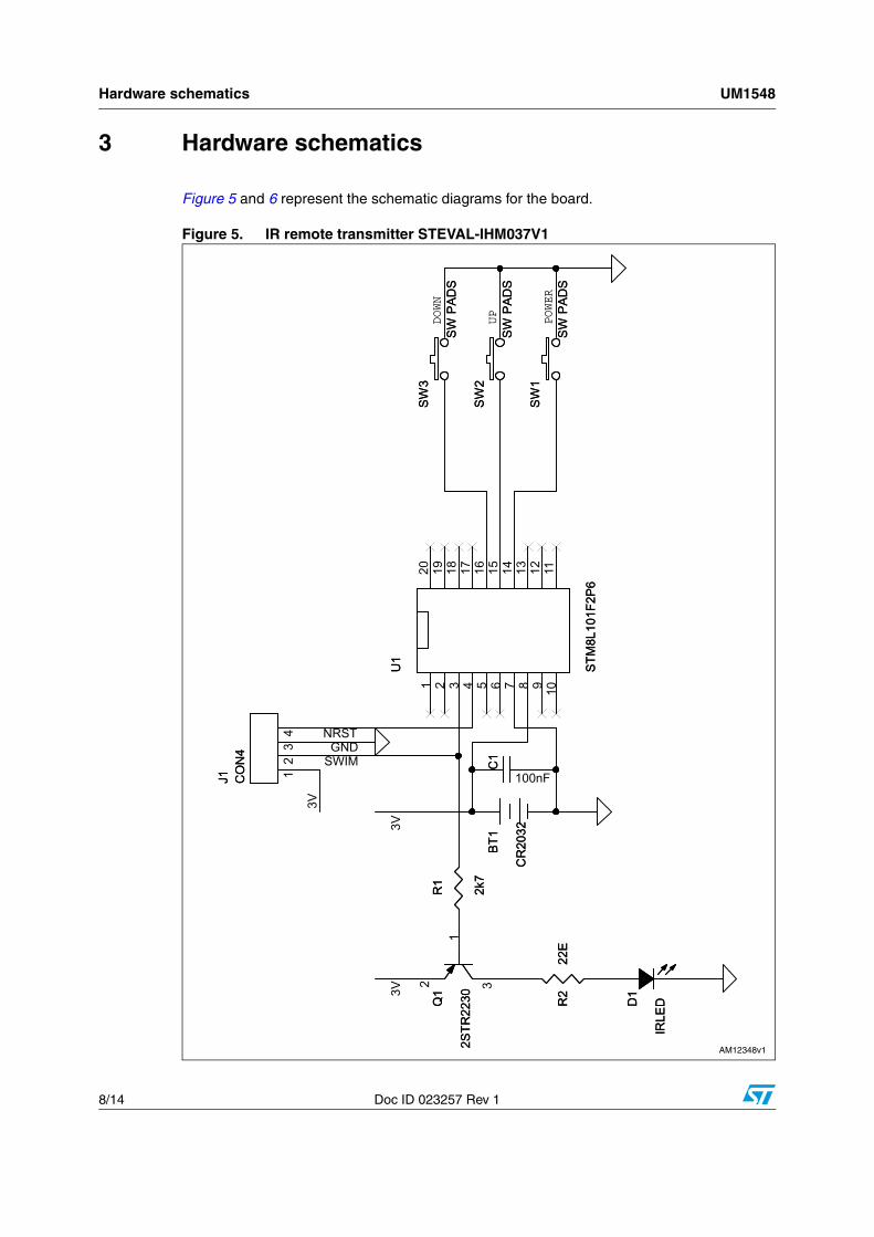
3 Hardware schematics
Figure 5 and 6 represent the schematic diagrams for the board.
Figure 5. IR remote transmitter STEVAL-IHM037V1

UM1548 Hardware schematics
Doc ID 023257 Rev 1 9/14
Figure 6. Remote fan speed controller

Hard
ware sch
ematics
UM
1548
10/14D
oc ID 023257 R
ev 1
3.1 Bill of materials
Table 2. BOM
CategoryReference designator
Component description
Package Manufacturer
Manufacturer’s ordering code / orderable part
number
Supplier Supplier ordering code
Document / project reference: BOM for the AC Fan speed controller/dimmer
ST devices
U1STM8S003F3 value
line series MCUTSSOP-20 STMicroelectronics STM8S003F3P6
Q1 Logic level TRIAC TO-220AB STMicroelectronics T435-600T
Q2 NPN transistor SOT-23 STMicroelectronics 2STR1160
Other devices
TSOPIR receiver 38 kHZ,
DOME AXIALTSOP 2.54 mm Vishay TSOP34838 Digi-key 751-1386-5-ND
D1Zener diode 5.6 V/
0.5 WSOD123 Any DDZ5V6B-7 Digi-key DDZ5V6BDICT-ND
D2 LL4148 SOD80 Any LLN4148 Digi-key LL4148FSCT-ND
Capacitors
C1470 µF/16 V electrolytic
Radial 8 mm diameter /
3.5 mm pitchAny Digi-key P5141-ND
C2, C6,C7,C8 100 nF ceramic SMD0805 Any
C4(1) 330 nF or 680 nF/X2 rated film capacitor
22.5 mm pitch VishayBFC238312334 or
BFC233920684Digi-key
2222 383 12334-ND or BC2591-ND
C5 100 pF ceramic SMD0805 Any
C9 470 nF ceramic SMD0805 Any
ResistorsR1,R5 100 Ω SMD0805 Any
R2 82, 2 W Leaded Yageo RSF200JB-82R Digi-key 82W-2-ND

Hard
ware sch
ematics
UM
1548
11/14D
oc ID 023257 R
ev 1
Resistors
R3 330 kΩ/0.5 W Leaded Any Digi-key PPC330KW-1CT-ND
R4,R6 4.7 kΩ SMD0805 Any
R7 100 kΩ SMD0805 Any
R8 2.7 kΩ SMD0805 Any
Switches SW1, SW2Pushbutton switch
right angle
Switch tactile SPST-NO 0.05
A 12 VTT Electronics SWT6-R6K Digi-key 987-1385-ND
Document / project reference: BOM for the IR remote transmitter
ST devicesU1
STM8L101 8-bit low power MCU
TSSOP-20 STMicroelectronics STM8L101F2P6
Q1 PNP transistor SOT-23 STMicroelectronics 2STR2260
Other devices
IRLED 940 nm IR LED3 mm through
holeVishay TSAL4400 Digi-key 751-1201-ND
BT13 V CR2032 battery
retainerMemory protection
devicesBK-833 Digi-key BHSD-2032-SMCT-ND
Capacitors C1 100 nF ceramic SMD0805 Any
Resistors R1 22 Ω SMD0805 Any
SwitchesSW1, SW2,
SW3(2)
Carbon contact pushbutton switch on
PCB
ENIG gold plated carbon contact switch
(PCB)
3
Enclosure N/ABOSS 3 button key
fob enclosureEnclosure Boss Enclosures 2955-20R-3 Farnell 1264656
1. C4 X2 rating is important for reliable operation. A DC rated capacitor (even rated at 1000 V DC) fails over time as it is not designed to withstand the stress conditions present on AC supply lines. Use 330 nF for 230 V AC nominal supply voltage and increase to 680 nF for 110 V AC supply.
2. SW1, SW2, SW3 are carbon contact footprints on the PCB while the actual carbon contact is integrated into the enclosure. Alternately, a 2-pin tactile SMD switch from MULTICOMP part no. DTSM-32S-B can be used on the same footprint.
Table 2. BOM (continued)
CategoryReference designator
Component description
Package Manufacturer
Manufacturer’s ordering code / orderable part
number
Supplier Supplier ordering code

Definitions UM1548
12/14 Doc ID 023257 Rev 1
Appendix A Definitions
Table 3. Definitions for acronyms
Acronym Definition
IR Infrared
MCU Micro controller unit

UM1548 Revision history
Doc ID 023257 Rev 1 13/14
Revision history
Table 4. Document revision history
Date Revision Changes
07-Dec-2012 1 Initial release.

UM1548
14/14 Doc ID 023257 Rev 1
Please Read Carefully:
Information in this document is provided solely in connection with ST products. STMicroelectronics NV and its subsidiaries (“ST”) reserve theright to make changes, corrections, modifications or improvements, to this document, and the products and services described herein at anytime, without notice.
All ST products are sold pursuant to ST’s terms and conditions of sale.
Purchasers are solely responsible for the choice, selection and use of the ST products and services described herein, and ST assumes noliability whatsoever relating to the choice, selection or use of the ST products and services described herein.
No license, express or implied, by estoppel or otherwise, to any intellectual property rights is granted under this document. If any part of thisdocument refers to any third party products or services it shall not be deemed a license grant by ST for the use of such third party productsor services, or any intellectual property contained therein or considered as a warranty covering the use in any manner whatsoever of suchthird party products or services or any intellectual property contained therein.
UNLESS OTHERWISE SET FORTH IN ST’S TERMS AND CONDITIONS OF SALE ST DISCLAIMS ANY EXPRESS OR IMPLIEDWARRANTY WITH RESPECT TO THE USE AND/OR SALE OF ST PRODUCTS INCLUDING WITHOUT LIMITATION IMPLIEDWARRANTIES OF MERCHANTABILITY, FITNESS FOR A PARTICULAR PURPOSE (AND THEIR EQUIVALENTS UNDER THE LAWSOF ANY JURISDICTION), OR INFRINGEMENT OF ANY PATENT, COPYRIGHT OR OTHER INTELLECTUAL PROPERTY RIGHT.
UNLESS EXPRESSLY APPROVED IN WRITING BY TWO AUTHORIZED ST REPRESENTATIVES, ST PRODUCTS ARE NOTRECOMMENDED, AUTHORIZED OR WARRANTED FOR USE IN MILITARY, AIR CRAFT, SPACE, LIFE SAVING, OR LIFE SUSTAININGAPPLICATIONS, NOR IN PRODUCTS OR SYSTEMS WHERE FAILURE OR MALFUNCTION MAY RESULT IN PERSONAL INJURY,DEATH, OR SEVERE PROPERTY OR ENVIRONMENTAL DAMAGE. ST PRODUCTS WHICH ARE NOT SPECIFIED AS "AUTOMOTIVEGRADE" MAY ONLY BE USED IN AUTOMOTIVE APPLICATIONS AT USER’S OWN RISK.
Resale of ST products with provisions different from the statements and/or technical features set forth in this document shall immediately voidany warranty granted by ST for the ST product or service described herein and shall not create or extend in any manner whatsoever, anyliability of ST.
ST and the ST logo are trademarks or registered trademarks of ST in various countries.
Information in this document supersedes and replaces all information previously supplied.
The ST logo is a registered trademark of STMicroelectronics. All other names are the property of their respective owners.
© 2012 STMicroelectronics - All rights reserved
STMicroelectronics group of companies
Australia - Belgium - Brazil - Canada - China - Czech Republic - Finland - France - Germany - Hong Kong - India - Israel - Italy - Japan - Malaysia - Malta - Morocco - Philippines - Singapore - Spain - Sweden - Switzerland - United Kingdom - United States of America
www.st.com