Embed Size (px)
Citation preview
July 2014
IRATA International code of practicefor industrial rope access
Part 2: Detailed guidance
The first edition of Part 2 was published in January 2010.The second edition was published in March 2013 plus amendments in March and September 2013.This third edition was published in July 2014.
Amendments issued since publication in July 2014
Amd. No Date Text affected
Published by:
IRATA InternationalFirst Floor, Unit 3Eurogate Business ParkAshfordKentTN24 8XWEngland
Tel: +44 (0)1233 754600
Email: [email protected]
Website: www.irata.org
Copyright © IRATA International 2014
ISBN: 978-0-9544993-4-1
IRATA International code of practice for industrial rope accessPart 2 of 5: Detailed guidance
© IRATA International Part 2: page 1 of 68 2014-Jul-01
Contents
Introduction....................................................................................................................................... 4
2.1 General................................................................................................................................ 4
2.2 Planning and management ................................................................................................. 6
2.2.1 Objective..................................................................................................................... 62.2.2 Planning...................................................................................................................... 62.2.3 Pre-work analysis ....................................................................................................... 62.2.4 Risk assessment ........................................................................................................ 72.2.5 Safety method statements.......................................................................................... 82.2.6 Procedures and personnel to be in place before work begins ................................... 82.2.6.1 Procedures............................................................................................................. 82.2.6.2 Personnel ............................................................................................................... 92.2.7 Management and supervision of the rope access site............................................... 9
2.3 Selection of rope access technicians................................................................................ 10
2.3.1 General..................................................................................................................... 102.3.2 Experience, attitude and aptitude............................................................................. 10
2.4 Competence...................................................................................................................... 12
2.5 Training ............................................................................................................................. 13
2.5.1 General..................................................................................................................... 132.5.2 IRATA International training, assessment and certification ..................................... 132.5.3 Additional skill levels ................................................................................................ 142.5.3.1 General..................................................................................................................... 142.5.3.2 Trainers and Instructors ........................................................................................... 152.5.3.3 Assessors (Level A/3) .............................................................................................. 152.5.3.4 Auditors .................................................................................................................... 16
2.6 Rope access managers, rope access safety supervisors and other supervisory/managementitems .......................................................................................................................................... 18
2.6.1 Rope access managers............................................................................................ 182.6.2 Rope access safety supervisors............................................................................... 182.6.3 Other supervisory/management items ..................................................................... 192.6.3.1 Disciplined working................................................................................................... 192.6.3.2 Access by non-IRATA International qualified personnel .......................................... 192.6.3.3 Company nominated person (the technical contact)................................................ 19
2.7 Selection of equipment...................................................................................................... 21
2.7.1 General..................................................................................................................... 212.7.1.1 Application-specific assessment .............................................................................. 212.7.1.2 Legal requirements................................................................................................... 212.7.1.3 Standards ................................................................................................................. 212.7.1.4 Load ratings/minimum static strength ...................................................................... 222.7.1.5 Equipment for work restraint, work positioning and fall arrest ................................. 222.7.1.5.1 Work restraint (travel restriction) equipment ............................................................ 222.7.1.6 Limits of equipment use and compatibility ............................................................... 232.7.1.7 Knowledge of equipment.......................................................................................... 232.7.2. Ropes (e.g. for anchor lines) .................................................................................... 232.7.3 Harnesses ................................................................................................................ 252.7.4 Connectors ............................................................................................................... 262.7.5 Descending devices ................................................................................................. 272.7.6 Ascending devices ................................................................................................... 292.7.7 Back-up devices ....................................................................................................... 302.7.8 Lanyards and slings ................................................................................................. 312.7.8.1 General..................................................................................................................... 312.7.8.2 Device lanyards and anchor lanyards ...................................................................... 32
IRATA International code of practice for industrial rope accessPart 2 of 5: Detailed guidance
© IRATA International Part 2: page 2 of 68 2014-Jul-01
2.7.8.3 Anchor slings ............................................................................................................ 322.7.8.4 Selection criteria for device lanyards, anchor lanyards and anchor slings .............. 332.7.8.5 Other information on lanyards .................................................................................. 332.7.9 Anchors .................................................................................................................... 352.7.10 Protectors for anchor lines ....................................................................................... 372.7.11 Work seats................................................................................................................ 372.7.12 Helmets .................................................................................................................... 382.7.13 Pulleys ...................................................................................................................... 382.7.14 Clothing and protective equipment........................................................................... 38
2.8 Marking and traceability .................................................................................................... 40
2.9 Records............................................................................................................................. 42
2.10 Inspection, care and maintenance of equipment .............................................................. 44
2.10.1 General procedures.................................................................................................. 442.10.2 Equipment manufactured from man-made fibres..................................................... 452.10.3 Metal equipment....................................................................................................... 472.10.4 Protective helmets.................................................................................................... 482.10.5 Disinfection of equipment ......................................................................................... 482.10.6 Equipment exposed to a marine environment.......................................................... 482.10.7 Storage ..................................................................................................................... 482.10.8 Equipment withdrawn from service .......................................................................... 482.10.9 Lifespan .................................................................................................................... 492.10.10 Alterations to equipment........................................................................................... 49
2.11 Primary rope access work methods................................................................................. 50
2.11.1 Double protection ..................................................................................................... 502.11.2 The anchor system (anchors and anchor lines) ....................................................... 522.11.3 Use of anchor lines................................................................................................... 562.11.3.1 Rigging and de-rigging ............................................................................................. 562.11.3.2 Protection methods for anchor lines......................................................................... 592.11.4 Additional safety measures ...................................................................................... 602.11.5 The use of knots....................................................................................................... 622.11.6 Work teams .............................................................................................................. 632.11.7 Pre-work checking.................................................................................................... 632.11.8 Exclusion zones........................................................................................................ 642.11.8.1 General..................................................................................................................... 642.11.8.2 Protection of third parties ......................................................................................... 642.11.8.3 Anchor area exclusion zone ..................................................................................... 652.11.8.4 Working edge hazard zone ...................................................................................... 652.11.9 Communication......................................................................................................... 652.11.10 Welfare ..................................................................................................................... 662.11.11 Emergency procedures ............................................................................................ 672.11.12 Reporting of incidents and accidents ....................................................................... 672.11.13 End of shifts.............................................................................................................. 682.11.14 Termination of a job.................................................................................................. 682.11.15 Expanded techniques............................................................................................... 68
Figure 2.1 — Example of the loading positions of a connector in a static strength test and thedifference in use, e.g. when loaded with a wide webbing lanyard ................................................. 28
Figure 2.2 — Illustration to show an example of an anchor sling and examples of different types oflanyard .......................................................................................................................................... 34
Figure 2.3 — Example of a scaffold knot (often referred to as a barrel knot)................................ 34
Figure 2.4 — Examples of the increase in loading on anchors, anchor lines and anchor slings causedby an increase in the Y angle......................................................................................................... 36
Figure 2.5 — Typical arrangements in a rope access anchor system........................................... 51
IRATA International code of practice for industrial rope accessPart 2 of 5: Detailed guidance
© IRATA International Part 2: page 3 of 68 2014-Jul-01
Figure 2.6 — Typical arrangements in a rope access anchor system to achieve minimum strengthrecommendations........................................................................................................................... 53
Figure 2.7 — Example of a lark’s-footed (choked) sling ................................................................ 55
Figure 2.8 — Example of how the angle at a deviation anchor affects its loading ........................ 56
Figure 2.9 — Example of a stopper knot for use at the end of anchor lines (in this example, half adouble fisherman’s knot) ................................................................................................................ 58
Figure 2.10 — Example of the potential danger of snagged anchor lines..................................... 61
Figure 2.11 — Examples of different types of exclusion zone....................................................... 66
Table 2.1 — Recommended minimum static strengths for connectors ......................................... 27
IRATA International code of practice for industrial rope accessPart 2 of 5: Detailed guidance
© IRATA International Part 2: page 4 of 68 2014-Jul-01
Part 2: Detailed guidance
Introduction
Part 2 builds on the principles and controls given in Part 1 and gives detailed guidance on how IRATAInternational provides a safe system of work.
This part should be read in conjunction with the other parts, in particular with Part 1 and relevantannexes in Part 3.
2.1 General
2.1.1 All work at height should have a goal of no accidents, incidents or dangerous occurrences.It is essential, therefore, that the entire work project is operated as a safe system of work.
2.1.2 There can be many different aspects to each work project that could influence the level ofsafety, e.g. the type of work to be carried out; site location; ease of access and egress; facilities foremergencies; interaction with other work going on at the site. All such potentially influencing factorsshould be taken into account, as each factor is likely to rely on the proper implementation of theothers for a safe system of work to be achieved. These factors should be considered whendetermining whether rope access is an appropriate method of work. The rope access method and therescue plan chosen initially may need to be modified when all factors have been considered.
2.1.3 To achieve a safe system of work, there needs to be good planning and an effectivemanagement system, including appropriate supervision for both the overall site and for the safety ofthe rope access team.
2.1.4 Different skills are required by rope access personnel, depending on their specificresponsibility, i.e. manager, rope access safety supervisor and rope access technician. It is essentialthat each person has a skill level appropriate for the work to be undertaken and the environment inwhich they are likely to be working.
2.1.5 Different work environments can present different levels of complexity or risk. Rope accessmethods can vary in their complexity due to the work environment but should be kept as simple aspossible. The level of complexity and degree of risk influences the:
a) planning, management and supervisory skills required;
b) skill levels and experience required by the rope access technicians;
c) choice of access method and equipment to be used.
2.1.6 To help achieve a safe rope access system, the following essential subjects are covered inthis code of practice, each in its own section or sections:
a) planning and management, see 2.2;
b) selection, competence, training and supervision of rope access technicians, and appropriatecomposition of the team, see 2.3, 2.4, 2.5 and 2.6;
c) equipment selection, use and maintenance, see 2.7, 2.8, 2.9 and 2.10;
d) work methods, see 2.11.
2.1.7 Planning and management should take account of the legislation applicable where thework is being undertaken. Legislation varies from country to country and sometimes from region to
IRATA International code of practice for industrial rope accessPart 2 of 5: Detailed guidance
© IRATA International Part 2: page 5 of 68 2014-Jul-01
region. See Part 4 for relevant national legislation for the UK. Legislation to be covered for otherjurisdictions might include:
a) work at height;
b) manual handling;
c) lifting;
d) hazardous substances;
e) personal protective equipment;
f) incident reporting;
g) first aid;
h) control of noise;
i) risk assessment (also known as job safety analysis; job hazard analysis);
j) emergency procedures;
k) plant, machinery and tools;
l) confined spaces;
m) electricity at work.
IRATA International code of practice for industrial rope accessPart 2 of 5: Detailed guidance
© IRATA International Part 2: page 6 of 68 2014-Jul-01
2.2 Planning and management
2.2.1 Objective
The primary objective behind the planning and management of rope access projects is to create awork environment that maximizes safety and minimizes the risk of error, possible incidents and injury,i.e. to provide a safe system of work.
2.2.2 Planning
Before any rope access project is considered, a documented system should be in place to define orprovide for at least the following:
a) a clear line-management structure showing the responsibilities of personnel;
b) a safety management policy, including procedures for effective internal audit monitoring andreview, which should incorporate corrective and preventative actions to be taken, and proceduresadequate to control the work;
c) appropriate insurance, e.g. for the rope access technicians, public liability and other aspectsrelevant to the worksite;
d) a risk assessment, which covers identification of hazards, assessment of the likelihood of anincident occurring and control measures to minimize the risk;
e) specific planning of the project, including the safety method statement and rescue plan;
f) prior agreement of operating procedures if rope access technicians from another company areworking in the same team;
g) confirmation that the rope access safety supervisor has the company’s authority to act whenevernecessary to ensure the safety of the rope access technicians, the public and the worksite;
h) the selection of competent personnel;
i) records of the competence of personnel, e.g. skill levels and experience;
j) how proper communication of relevant information to all staff is to be provided;
k) the selection of appropriate equipment;
l) a list of equipment with inspection records;
m) specific procedures to deal with hazardous materials, machinery, fixtures and tools, andenvironmental hazards.
2.2.3 Pre-work analysis
A pre-work analysis should be carried out before rope access work is undertaken on a project toconfirm that rope access is a suitable method and to ensure control systems are in place to allow thework to be carried out safely. Examples of typical points to be covered are:
a) how the work area can be accessed and exited safely;
b) the ease and degree of safety with which a rope access technician will be able to use tools andequipment while suspended;
IRATA International code of practice for industrial rope accessPart 2 of 5: Detailed guidance
© IRATA International Part 2: page 7 of 68 2014-Jul-01
c) whether there might be a risk of loose materials or equipment falling onto people below;
d) whether the duration of the work in a location might put the rope access technician at risk, e.g.prolonged exposure to extremes of heat or cold;
e) whether rope access technicians could be rescued quickly from any potential position in whichthey might find themselves.
2.2.4 Risk assessment
2.2.4.1 Once it has been decided that rope access is a suitable method to carry out the intendedtask, employers should review carefully the procedures to be followed for carrying out the work. Theyshould identify any hazards and examine how they can be removed or, if this is not possible, how therisk can be reduced to an acceptable level. This is determined by carrying out a risk assessment,which is also known as a job safety analysis (JSA). For more information on risk assessment, seePart 3, Annex A.
2.2.4.2 The detail provided in the risk assessment should be in proportion to the risk. Once therisks are assessed and taken into account, insignificant risks can then often be ignored, unless thetype of work to be carried out would increase those risks.
2.2.4.3 Hazard identification should comprise identification of anything with the potential tocause harm, for example:
a) power cables, which could pose a high risk of electric shock;
b) any hazard placing the public or other workers at risk, in particular, persons working on theground on to which debris or tools could be dropped;
c) the presence of other trades;
d) the tools being used;
e) moving or carrying heavy machinery, tools or other equipment;
f) repetitive use of tools or equipment;
g) the unavailability of anchor points of suitable size, shape and strength for the proposed accessmethod and work to be carried out;
h) sharp or rough edges on which the anchor lines could be cut or abraded;
i) hot surfaces or hot work that could damage anchor lines or injure rope access technicians;
j) hazardous substances, e.g. toxic gases, acids, asbestos;
k) radio waves, radiation;
l) adverse weather conditions.
2.2.4.4 After the hazards have been identified, the risk assessment should continue with acareful study of all the hazards identified, to determine the level of risk posed by each. As a first step,wherever possible, hazards should be eliminated. If this is not possible, precautions should be takento minimize the likelihood of persons being harmed. Thus, the chance of an incident occurring in thefirst place is reduced. In addition, the undesirable possibility of having to deal with an incident and itsconsequences is also reduced.
2.2.4.5 The hazard identification and risk assessment should be site specific. They should bedocumented and should cover all aspects of the work to be undertaken. The document(s) should be
IRATA International code of practice for industrial rope accessPart 2 of 5: Detailed guidance
© IRATA International Part 2: page 8 of 68 2014-Jul-01
available to personnel working on-site and should be regularly reviewed formally by them during thecourse of the work, to take account of changing circumstances, e.g. weather conditions and otherwork being carried out. Operations such as oil platforms, refineries, power stations and railways havea formal written permit-to-work system to address hazards, by requiring certain precautions to betaken. Examples are: electrical isolations; restriction of other work; communication requirements;specified personal protective equipment.
2.2.4.6 The risk assessment should include detailed consideration of foreseeable emergencyscenarios and planning as to how any rescue would be carried out.
2.2.5 Safety method statements
2.2.5.1 Planning should not only include the selection of appropriate working methods,equipment and competent personnel but should also include the preparation of a safety methodstatement. Safety method statements are an effective way of producing an action plan for a safesystem of work and are useful in bringing together the assessments of the various hazards that mayarise on a job.
2.2.5.2 The safety method statement should set out working procedures to be followed for eachparticular job. All safety method statements should include a specific rescue plan, e.g. rigging forrescue.
2.2.5.3 In cases where types of jobs are similar, the safety method statements could be identicaland may, therefore, be in the form of a general document. However, separate safety methodstatements may be necessary for each particular aspect of the job. Where the work includes the useof hazardous tools (e.g. welding torches, flame cutters, abrasive wheels), a more detailed safetymethod statement should be prepared. For advice on preparing a safety method statement, see Part3, Annex B.
2.2.6 Procedures and personnel to be in place before work begins
2.2.6.1 Procedures
Before work begins, at least the following procedures should be in place to enable a rope accessteam to carry out a task safely:
a) a documented system of work;
b) a documented safety method statement;
c) permits to work, where necessary;
d) site induction requirements;
e) hand-over procedures, e.g. between shift changes or site contractors;
f) site-specific documentation, e.g. rope access technicians’ log books; end of shift documentation;hours worked/accident/incident report forms; work log; equipment user instructions. For arecommended list of information to be kept on site, see Part 3, Annex N;
g) worksite facilities, e.g. for resting; for emergency washing; showers; toilets;
h) where appropriate, a documented site inspection, including suitable provision for anchors, and arigging/rescue plan;
i) planning for emergencies, e.g. fire; entrapment (including rescue), including any equipmentrequired;
j) protection of third parties, e.g. exclusion zones; barriers; warning signs.
IRATA International code of practice for industrial rope accessPart 2 of 5: Detailed guidance
© IRATA International Part 2: page 9 of 68 2014-Jul-01
2.2.6.2 Personnel
Before work begins, there should be at least the following personnel in place to enable a rope accessteam to carry out a task safely:
a) a rope access manager with overall responsibility for the rope access site;
b) an appropriate number of trained, assessed and suitably equipped rope access technicians, witha minimum of two, one of which is a Level 3 rope access safety supervisor;
NOTE It may be necessary for there to be more than one Level 3 rope access safety supervisor, dependingon the number of rope access technicians on site.
c) additional assisting personnel as required, e.g. sentries; traffic monitors.
2.2.7 Management and supervision of the rope access site
2.2.7.1 Rope access worksites should be properly managed and supervised to ensure the safetyof those involved in the rope access project.
2.2.7.2 There should be a rope access manager, who is responsible for determining that ropeaccess is an appropriate method of work and for defining, planning, implementing and reviewing theoperation of a safe system of work.
2.2.7.3 Worksites using rope access require the supervision of rope access safety and of thework project itself. These two types of supervision may be the responsibility of different people or thesame person. This code of practice covers only the supervision of rope access safety.
2.2.7.4 For more information on rope access managers and rope access safety supervisors, see2.6.
IRATA International code of practice for industrial rope accessPart 2 of 5: Detailed guidance
© IRATA International Part 2: page 10 of 68 2014-Jul-01
2.3 Selection of rope access technicians
2.3.1 General
2.3.1.1 To work at height safely requires personnel to have an appropriate attitude, aptitude,physical capability and training. Therefore, some form of screening is required to assess properly allprospective employees.
2.3.1.2 It is important that rope access technicians can be relied upon to behave in a sensibleand responsible manner.
2.3.1.3 Rope access technicians should be physically fit and free from any disability that mightprevent them from working safely at height. Contra-indications include:
a) alcohol or drug dependence;
b) diabetes; high or low blood pressure;
c) epilepsy, fits, blackouts;
d) fear of heights;
e) vertigo/giddiness/difficulty with balance;
f) heart disease/chest pain;
g) high or low blood pressure;
h) impaired limb function;
i) musculoskeletal issues, e.g. a bad back;
j) obesity;
k) psychiatric illness.
2.3.1.4 It is the responsibility of the trainee or their employer to ensure that the trainee isphysically and medically fit to undergo rope access training.
2.3.1.5 Employees have a responsibility to their employers and their work colleagues to notifyany changes in their physical and medical condition which may affect their work. This includes theeffects of alcohol or drugs.
2.3.1.6 Rope access technicians should be given the opportunity not to work at height if they donot feel fit enough to do so.
2.3.2 Experience, attitude and aptitude
2.3.2.1 All persons working at height need to have at least elementary background awareness ofdifferent fall protection methods, e.g. fall arrest; work restraint; safety net systems; air bags; mobileelevating work platforms, in addition to that required for rope access.
2.3.2.2 To assess whether a person is suitable to work in rope access requires detailedconsideration of their previous experience. References should be taken up to verify claimedexperience and levels of competence.
2.3.2.3 Employers should also consider relevant trade experience and skills, to ensure safe useof tools and equipment.
IRATA International code of practice for industrial rope accessPart 2 of 5: Detailed guidance
© IRATA International Part 2: page 11 of 68 2014-Jul-01
2.3.2.4 Employers should seek to ensure that rope access technicians, including trainees, havea suitable attitude and aptitude in addition to their IRATA International qualification. These include:
a) a head for heights;
b) a natural ability or potential for rope access work;
c) the ability to work in a team;
d) a responsible attitude to safety;
e) a willingness to improve their skills;
f) a professional standard of behaviour.
2.3.2.5 Consideration should be given to the composition of a rope access team, as teamwork,work skills, rescue capability and the correct level of supervision are essential.
2.3.2.6 The selection of team members should take into account the specific tasks to beundertaken.
IRATA International code of practice for industrial rope accessPart 2 of 5: Detailed guidance
© IRATA International Part 2: page 12 of 68 2014-Jul-01
2.4 Competence
2.4.1 Rope access work can only be carried out in a reliably safe manner where people arecompetent. To be considered competent, a rope access technician needs to have sufficientprofessional or technical training, knowledge, actual experience and authority to enable them to:
a) carry out their assigned duties at the level of responsibility allocated to them;
b) understand potential hazards related to the work under consideration and be able to carry outappropriate workmate rescue procedures;
c) detect technical defects or omissions in their work and equipment, recognize implications forhealth and safety caused by such defects or omissions, and be able to specify a remedial actionto mitigate those implications.
2.4.2 Rope access technicians should have adequate skill and experience to:
a) understand the limitations of their level of training with regard to work practices;
b) understand the various uses of the equipment they use and its limitations;
c) select equipment correctly;
d) use the equipment properly;
e) inspect their equipment;
f) maintain and store the equipment they use.
2.4.3 It is essential that rope access personnel maintain their knowledge of industry bestpractices, equipment developments and current legislation.
IRATA International code of practice for industrial rope accessPart 2 of 5: Detailed guidance
© IRATA International Part 2: page 13 of 68 2014-Jul-01
2.5 Training
NOTE Wherever the terms Level 1, Level 2, Level 3, assessor, auditor and trainer are used, theserefer to IRATA International qualifications, whether it states so or not.
2.5.1 General
2.5.1.1 As a general rule, training should be either provided or monitored by an expert externalorganization or person, to ensure that the standard is to an externally certificated level. Trainingroutes should be clearly defined. Assessments should only be carried out by assessors who arecommercially independent of the candidate, the candidate’s company and the organization providingthe training.
2.5.1.2 Procedures should be in place to document the work at height and rope accessexperience of rope access technicians, and to allow certification bodies to verify the rope accesstechnicians’ experience. Documented experience is also useful for prospective employers to enablethem to judge the suitability of personnel for various tasks.
2.5.2 IRATA International training, assessment and certification
2.5.2.1 IRATA International has a formal training syllabus, assessment and certification scheme,and grading structure, which meets the criteria set out in 2.5.1.1 and 2.5.1.2. All IRATA Internationalmembers are obliged to use this scheme. Rope access technicians are grouped into three technicalgrades, depending upon their experience and level of assessment as set out in the publication IRATAInternational training, assessment and certification scheme for personnel engaged in industrial ropeaccess methods (TACS). The three technical grades are:
a) Level 1
This is a rope access technician who is able to perform a specified range of rope access tasks underthe supervision of a Level 3 rope access safety supervisor.
b) Level 2
This is an experienced rope access technician who has Level 1 skills plus more complex rigging,rescue and rope access skills, under the supervision of a Level 3 rope access safety supervisor.
c) Level 3
This is a rope access technician who is able to demonstrate the skills and knowledge required ofLevels 1 and 2; is conversant with relevant work techniques and legislation; has an extensiveknowledge of advanced rigging and rescue techniques; holds an appropriate and current first aidcertificate and has knowledge of the IRATA International training, assessment and certificationscheme. Subject to a Level 3 having the necessary supervisory skills, he/she can become a ropeaccess safety supervisor with responsibility for rope access safety in work projects: see 2.5.2.6 and2.6.
2.5.2.2 To become an IRATA International Level 1 rope access technician, candidates have toundertake an IRATA International approved training course of a minimum of four days followed by aone-day assessment by an independent IRATA International assessor. Once the training course andassessment have been satisfactorily completed, the person may then be allowed to work using ropeaccess techniques, although this has to be under close supervision.
2.5.2.3 Special precautions should be taken for newly qualified rope access technicians. Theseinclude only gradually introducing them to the work and initially only allowing them to carry out themost straightforward operations, under the direct control of a rope access safety supervisor. As therope access safety supervisor becomes satisfied that they are fit to do so, the new rope accesstechnicians should then be allowed to progress gradually to more complex work, although still underclose supervision. At this stage, the rope access safety supervisor should check that all items of the
IRATA International code of practice for industrial rope accessPart 2 of 5: Detailed guidance
© IRATA International Part 2: page 14 of 68 2014-Jul-01
inexperienced rope access technician’s suspension equipment are correctly secured before they areallowed to start work.
2.5.2.4 Rope access technicians are in the learning process for some time after completing theirbasic training. They should, therefore, be continuously assessed by the rope access safety supervisorand not allowed to work without close supervision until the rope access safety supervisor is satisfiedthat they have achieved a suitable level of competency. This would be when they had demonstratedthat they had suitable knowledge and experience to carry out the full range of tasks that they werelikely to encounter in a safe and effective manner, and were capable of acting properly within thelimits of their level of competency and in any emergency that might reasonably arise.
2.5.2.5 To achieve the next level, i.e. Level 2 rope access technician, where the person could beregarded as an experienced worker, Level 1 technicians have to log at least 1 000 working hoursusing rope access techniques and have worked for a minimum of one year at Level 1. They have thento undergo a minimum of four days further training plus an assessment by an independent IRATAInternational assessor.
2.5.2.6 Before a Level 2 can become a Level 3 rope access technician, a minimum of one yearat Level 2 and at least a further 1 000 working hours using rope access techniques have to be logged,i.e. a combined minimum total of two years and 2 000 hours at Level 1 and Level 2. A minimum offour days of further training and then assessment by an independent IRATA International assessorare required. This is particularly to ensure that the person has the necessary technical skills for thislevel and may be ready to prove their competence to supervise rope access safety. It is theemployer’s responsibility to ensure that Level 3s are competent to supervise. See 2.6 for informationon rope access safety supervisors.
2.5.2.7 It is essential that employers ensure their employees are competent. To ensure that alllevels of rope access technician maintain their skill level, a further training course followed byreassessment is required every three years.
2.5.2.8 Due to the aptitude and mental conditioning that are needed for exposure to height, ropeaccess technicians who have not been engaged in rope access work for six months or more arerequired to attend a suitable refresher course before being allowed to work in this manner. This maybe either a refresher course or a full course at the appropriate level. The refresher courses shouldinclude all the techniques covered during Level 1 training. For Level 2 and Level 3 rope accesstechnicians, the refresher course should concentrate on rigging and rescue procedures (see thepublication IRATA International training, assessment and certification scheme for personnel engagedin industrial rope access methods (TACS).
2.5.2.9 As part of on-going training, rescue procedures should be practised at regular intervalsand before the start of any work in situations that are unfamiliar to any of the work team (see 2.11.11).
2.5.2.10 Rope access technicians are registered under the IRATA International training,assessment and certification scheme and are issued with a personal logbook that is used todocument their work experience and any relevant training received. As detailed within the scheme,logbook entries should be countersigned by an IRATA International rope access safety supervisor.Employers taking on new rope access technicians should assess and, where necessary, verify theinformation contained in their logbooks to confirm suitability for the work to be undertaken (see 2.3.2).
2.5.3 Additional skill levels
2.5.3.1 General
In addition to becoming a rope access safety supervisor, IRATA International Level 3 rope accesstechnicians may specialize in up to four categories of additional skills. These are trainers, instructors,assessors and auditors.
IRATA International code of practice for industrial rope accessPart 2 of 5: Detailed guidance
© IRATA International Part 2: page 15 of 68 2014-Jul-01
2.5.3.2 Trainers and instructors
2.5.3.2.1 IRATA trainer member companies appoint suitable Level 3 rope access technicians toact as trainers, who are then employed to train applicants to the three rope access technician grades,i.e. Levels 1, 2 and 3.
2.5.3.2.2 IRATA Level 3 rope access technicians with extensive training experience may gainadditional certification as IRATA rope access instructors (Level 3/I).
2.5.3.2.3 Level 1 and Level 2 rope access technicians may be engaged in training as assistants toa Level 3 rope access trainer or Level 3 rope access instructor. Such Level 2 assistant trainers mayregister with IRATA as trainee instructors and begin to log their training experience, but may not teach(or log) Level 2 or Level 3 topics until they are qualified at IRATA Level 3.
NOTE The qualifications of the rope access technicians carrying out training (i.e. trainer, assistant trainer,instructor, assistant instructor) and the qualification levels of the trainees determine the maximum number oftrainees allowed to be trained in any one group at any one time.
2.5.3.2.4 It should be noted that only IRATA qualified rope access technicians are allowed toassist in training courses.
2.5.3.2.5 Trainee instructors are required to log at least 400 hours of training experience beforethey are eligible to apply for full instructor status.
2.5.3.2.6 Rope access technicians wishing to become trainee instructors first need to gain thesponsorship of an IRATA trainer member company.
2.5.3.2.7 For details of trainer and instructor requirements, see the publication IRATA Internationaltraining, assessment and certification scheme for personnel engaged in industrial rope accessmethods.
2.5.3.3 Assessors (Level A/3)
2.5.3.3.1 IRATA International appoints assessors, who are then employed by IRATA Internationaltrainer member companies to carry out independent assessments of rope access technicians whohave completed an IRATA International training course operated by an IRATA International membercompany.
2.5.3.3.2 The primary rôle of the assessor is to ensure that each candidate demonstratesperformance of the required tasks in a safe manner, in accordance with the current edition of theIRATA International training, assessment and certification scheme for personnel engaged in industrialrope access methods and this code of practice.
2.5.3.3.3 Assessors are responsible for rope access assessment to Levels 1, 2 and 3.
2.5.3.3.4 To be eligible to become an assessor, applicants are required to have been working as aLevel 3 rope access technician for a minimum of six years.
2.5.3.3.5 Assessors are appointed at the discretion of the Executive Committee on therecommendation of the Training Committee.
2.5.3.3.6 Applicants are required to provide credentials at the time of application and are expectedto retain the necessary knowledge, skills and physical fitness required during the full period of theappointment. This includes the Level 3 qualification.
2.5.3.3.7 Once appointed, assessors may conduct assessments on behalf of IRATA Internationalonly in conformance with the current editions of the IRATA International training, assessment and
IRATA International code of practice for industrial rope accessPart 2 of 5: Detailed guidance
© IRATA International Part 2: page 16 of 68 2014-Jul-01
certification scheme for personnel engaged in industrial rope access methods, this code of practiceand any amendments published on the IRATA International website.
2.5.3.3.8 IRATA International assessors are required to abide by the IRATA Internationaldocument Requirements and guidance for IRATA assessors and assessments.
2.5.3.3.9 To retain their status, assessors are required to:
a) attend at least one assessors’ workshop per year;
b) assess twenty candidates per year (unless a lower figure has been previously agreed), coveringall levels of rope access technician;
c) hold valid Level 3, first-aid and insurance certificates.
2.5.3.4 Auditors
IRATA International appoints auditors to carry out audits of companies applying for membership ofIRATA International and re-audits, which are required every three years. Auditors undergo externalauditor training.
IRATA International code of practice for industrial rope accessPart 2 of 5: Detailed guidance
© IRATA International Part 2: page 17 of 68 2014-Jul-01
This page is intentionally blank
IRATA International code of practice for industrial rope accessPart 2 of 5: Detailed guidance
© IRATA International Part 2: page 18 of 68 2014-Jul-01
2.6 Rope access managers, rope access safety supervisors and othersupervisory/management items
2.6.1 Rope access managers
2.6.1.1 Rope access managers are responsible for determining that rope access is anappropriate method of work, and for defining, planning, implementing and reviewing the operation of asafe system of work. They should have:
a) competence and experience for the work being managed;
b) the ability to communicate requirements to rope access safety supervisors;
c) the ability to create, implement and review control systems, and be able to assess which controlmeasures are appropriate for each project;
d) the ability to ensure correct operation of the rope access management system.
2.6.1.2 Rope access managers have a duty to ensure that rope access safety supervisors andother rope access technicians are competent for the particular rope access task in hand.
2.6.1.3 Employers should ensure that rope access managers have the necessary managementskills before they are given such a rôle. Some form of training in management plus an assessment isrecommended. There should be a clearly defined reporting system to senior management.
NOTE In a small organization, the senior manager, rope access manager and rope access safety supervisormight be the same person.
2.6.2 Rope access safety supervisors
2.6.2.1 This code of practice covers only the supervision of rope access safety and not the workproject itself.
2.6.2.2 The rope access safety supervisor’s rôle is to ensure that the work and the workersproceed in accordance with this code of practice, in the manner set out in the documentation for thework project and with the aim of no accidents, no waste and no defects (known as zero targeting).
2.6.2.3 It is essential that rope access safety supervisors have the experience and competenceto supervise the rope access work and any potential rescue for each rope access project under theirsupervision.
2.6.2.4 Under the IRATA International scheme, only Level 3 rope access technicians arepermitted to be rope access safety supervisors. Employers should ensure that Level 3s have thenecessary supervisory skills before they are given such a rôle, as rope access technical skills aloneare no assurance that a Level 3 is competent to supervise. Some form of training in supervision plusan assessment is recommended.
2.6.2.5 Level 3 rope access safety supervisors require:
a) the experience and competence to supervise the rope access work and any potential rescue foreach rope access project under their supervision;
b) the ability to communicate to rope access technicians the rope access safety requirements for theproject and to manage day-to-day problems on the site;
c) leadership abilities appropriate to the work team;
IRATA International code of practice for industrial rope accessPart 2 of 5: Detailed guidance
© IRATA International Part 2: page 19 of 68 2014-Jul-01
d) the ability to monitor closely both worksite and personnel for rope access safety and to be able toidentify any shortfalls in the required competence of those personnel;
e) a thorough knowledge of hazard identification and risk assessment, and methods of sitemanagement;
f) the ability to understand and implement the content of safety method statements;
g) the ability to complete and maintain relevant documentation;
h) the authority to make decisions to ensure the safety of rope access technicians, the public andthe rope access worksite, e.g. the withdrawal of equipment from service if thought to beinappropriate or unsafe.
2.6.2.6 Different levels of rope access safety supervisor skills may be required for differentaccess tasks, dependent upon the precise nature of the work. This could apply when the work task isunfamiliar, complex or possibly hazardous, e.g. working in confined spaces; working with chemicals;working with potentially dangerous tools, and in relation to the ability to provide adequate cover foremergencies.
2.6.2.7 In every case, the level of supervision should be appropriate to the particular worksituation and the numbers and skills of the work team.
2.6.2.8 The rope access safety supervisor should ensure every rope access technician andother members of the work team under his/her supervision understand the work procedures prior towork commencing.
2.6.2.9 Rope access safety supervisors should be familiar with their work environment, theworking conditions and practices, and, in particular, the essential liaison necessary with otherworkplace personnel.
2.6.2.10 There should be a clearly defined reporting system to the rope access manager.
2.6.3 Other supervisory/management items
2.6.3.1 Disciplined working
As part of their duties to maintain a safe place of work, employers should control any tendency ofemployees to work in an undisciplined manner by recording this in their personal logbooks and shouldnot cancel any adverse comments until completely satisfied that there would be no recurrence.
2.6.3.2 Access by non-IRATA International qualified personnel
The person responsible for the work site should only allow rope access methods to be carried out byexperienced rope access technicians, trained and assessed to IRATA International standards. Thisincludes any representative of the client. However, occasions may arise where a client’srepresentatives or other people not employed by the contractor need to inspect the work. Both thecontractor and the client should arrange systems to ensure that such persons will be able to do thissafely. This could be done, for example, by providing additional top-rope protection (i.e. protect theperson with an additional safety line from above). In addition, the rope access safety supervisorshould check personally that all items of such a person's suspension equipment are correctly securedand of a suitable standard and condition. They should then supervise them throughout the ascent ordescent as though they were new trainees.
2.6.3.3 Company nominated person (the technical contact)
Companies employing rope access techniques should nominate one person to be the main contactpoint between IRATA International and the company for matters relating to IRATA International safetytraining, this code of practice and other IRATA International documentation. This company nominated
IRATA International code of practice for industrial rope accessPart 2 of 5: Detailed guidance
© IRATA International Part 2: page 20 of 68 2014-Jul-01
person, also known as the technical contact, should be suitably knowledgeable, experienced andqualified in such matters or have access to a person or persons within the company who are.
IRATA International code of practice for industrial rope accessPart 2 of 5: Detailed guidance
© IRATA International Part 2: page 21 of 68 2014-Jul-01
2.7 Selection of equipment
2.7.1 General
2.7.1.1 Application-specific assessment
An assessment should be carried out before each job to select the most appropriate equipment to beused. Where the suitability of a piece of equipment is unknown, it should be thoroughly evaluatedand/or tested before it is used. Rope access equipment should be selected only for its intendedpurpose as specified by the manufacturer. If equipment is to be used for other applications,confirmation should be obtained from the manufacturer that it is acceptable to do so and any caveatsshould be taken into account. The assessment should also pay special attention to the probability andconsequences of misuse of equipment, taking into account any known incidents, e.g. as detailed inIRATA International safety bulletins. The selection and purchase of equipment should be carried outby, or approved by, a competent person, who has sufficient knowledge of the technical specificationsrequired.
2.7.1.2 Legal requirements
2.7.1.2.1 Equipment should be chosen which satisfies legal requirements in the country of use.These requirements vary from country to country and sometimes from region to region. See Part 4 forrelevant national legislation.
2.7.1.2.2 Generally, it is not a legal requirement for equipment to conform to standards. However,it should be noted that they may be used to support the law.
2.7.1.3 Standards
2.7.1.3.1 Generally, equipment should be selected that conforms to national or internationalstandards. It is important that the selected standards are relevant to the intended use. For a list ofstandards referred to in this code of practice, see Part 3, Annex C.
2.7.1.3.2 For many years, workplace standards did not cover much of the equipment used in ropeaccess and equipment meeting standards for mountaineering and caving was often used. There arenow workplace standards that cover almost all personal fall protection equipment used in ropeaccess. Equipment conforming to these standards should be chosen, wherever possible.
2.7.1.3.3 Equipment that conforms to an appropriate standard is important, but is not the solefactor in the selection criteria. Sometimes, a standard might not cover all the requirements advisablefor rope access use and equipment with the desired features might render it out of conformance withthe standard. In some cases, equipment that conforms to a combination of requirements from morethan one standard, e.g. a hybrid of two standards, might be more appropriate. The equipmentmanufacturer or his authorized representative should be able to provide information.
2.7.1.3.4 Similarly, just because a piece of equipment does not claim conformity to a particularstandard, it does not necessarily mean that it is unfit for use. For example, when a revision, i.e. anupdate, of a standard is published, it does not necessarily mean that equipment that conforms to theold version can no longer be used. This would only be the case if serious safety issues had beendetected in products conforming to these earlier standards and/or in the standards themselves.However, if a product has been tested to the most recent version of an appropriate standard, it shouldgive some confidence that it will be safe for its intended use. The same points apply to equipment notconforming to local legislative requirements, e.g. CE marking; OSHA.
2.7.1.3.5 Manufacturers should not claim product conformity to draft standards but, in cases wherethere is no appropriate standard of any kind, this is sometimes the only feasible option. Purchasersshould be aware that a draft standard could change.
IRATA International code of practice for industrial rope accessPart 2 of 5: Detailed guidance
© IRATA International Part 2: page 22 of 68 2014-Jul-01
2.7.1.3.6 If there is any doubt about whether or not a particular standard is relevant to the intendeduse, guidance should be sought from the manufacturer of the equipment or his authorizedrepresentative.
2.7.1.4 Load ratings/minimum static strength
2.7.1.4.1 Manufacturers’ specifications for the permissible loading of equipment should be takenas the starting point for the selection of equipment. Some equipment, e.g. descending devices; back-up devices, may be supplied with maximum and/or minimum rated loads (RLMAX and RLMIN). Otherequipment may be supplied with different types of load ratings, e.g. a safe working load (SWL);working load limit (WLL). These are sometimes in addition to the minimum static strength provided,e.g. connectors, and sometimes in place of it. Most personal fall protection equipment used in ropeaccess work, such as low-stretch ropes, harnesses and ascending devices, is tested using theminimum static strength specified in the relevant standards. Dynamic rope is supplied with astatement of the number of dynamic falls held during type testing.
NOTE It is reiterated that, apart from safe working loads, working load limits and minimum and maximumrated loads, static strength requirements in standards are usually minimums. Equipment with a higher staticstrength is likely to provide a higher level of protection.
2.7.1.4.2 Some countries or regions, e.g. USA, have statutory minimum strength requirements forequipment, which might be higher than those given in this code of practice. Purchasers of equipmentshould check their local legislation.
2.7.1.5 Equipment for work restraint, work positioning and fall arrest
2.7.1.5.1 Work restraint (travel restriction) equipment
If the objective is to restrict the user’s travel so that access is not possible to zones where the risk of afall from a height exists, work restraint equipment may be used. This could be fall arrest equipment,work positioning equipment, or even a simple belt and lanyard of limited length and strength. Differentcountries or states may have their own regulations with regard to what is acceptable. To ensure theuser is working in restraint, there should be no fall hazards within reach of the user. For moreinformation on work restraint, see Annex L.
2.7.1.5.2 Work positioning equipment
If the planned method of work is for the user to be in a partly or entirely supported position, as is thenormal case for rope access work, then work positioning equipment may be chosen. In addition to itsprimary function of providing support, this equipment is designed to be strong enough to arrest a freefall of limited distance and force but will not meet the other essential requirements of a fall arrestsystem, unless combined with appropriate components. Information on limited free falls will beprovided at some future date in Part 3. Work positioning harnesses for rope access work may be a sitharness or full body harness, dependent upon the precise nature of the work to be carried out. In workpositioning, there should be minimal slack in the system, e.g. dynamic rope anchor lanyards used inhorizontal aid climbing or with a horizontal traverse line should be attached above the rope accesstechnician’s harness attachment point in such a way as to ensure little or no slack, thereforeminimizing the consequences of a fall. For more information on work positioning, see Annex L.
2.7.1.5.3 Fall arrest equipment
If the planned method of work is such that should the user lose controlled physical contact with theworking surface there would be a significant free fall (outside the normal bounds of rope access, e.g.lead climbing, see 2.11.16), it is necessary to choose fall arrest equipment. This includes anappropriate full body harness and a system that limits the impact load to an acceptable level. Thislevel varies internationally between 4 kN and 8 kN. Maximum impact loads are usually controlled bythe use of commercially made energy absorbers. For more information on fall arrest, see Annex L.
IRATA International code of practice for industrial rope accessPart 2 of 5: Detailed guidance
© IRATA International Part 2: page 23 of 68 2014-Jul-01
2.7.1.6 Limits of equipment use and compatibility
2.7.1.6.1 Equipment designed specifically for work restraint should not be used for workpositioning or as fall arrest equipment. Equipment designed specifically for work positioning shouldnot be used as fall arrest equipment. Some equipment is designed to allow the attachment orconnection of other components in order to meet the requirements of a category of work other thanthe one for which it was primarily designed. An example is a sit harness (for work positioning) whichis designed to accept the connection of a chest harness which will allow these two combined parts tomeet the requirements of a full body harness (for fall arrest).
2.7.1.6.2 Purchasers should ensure that components in any system are compatible and that thesafe function of any one component does not interfere with the safe function of another.
2.7.1.6.3 Equipment should only be used in accordance with the information supplied by themanufacturer.
2.7.1.6.4 The equipment chosen should be able to withstand any loads or forces that might beimposed on it, plus an additional adequate safety margin, and the rope access system itself should bedesigned to minimize the potential loads placed upon it. The rope access system generally should bedesigned to avoid a fall.
2.7.1.6.5 No item of rope access equipment should be capable of being accidentally removed,dislodged or become unfastened from the anchor lines during use.
2.7.1.6.6 When choosing equipment for a particular application, account should be taken ofweakening factors, such as the loss of strength at knots (see 2.11.5).
2.7.1.6.7 Rope access technicians should be aware that climatic conditions can affect theperformance of some equipment or combinations of equipment. For example, humidity can alter(reduce) the friction provided between the descending device and the anchor line, and thus theperformance is altered. This also applies to some ascending devices. Cold conditions can also affectperformance, e.g. icy anchor lines can affect the grip of anchor line devices on them. Wet anchor linescan exhibit greater elongation characteristics than dry ones and wet polyamide anchor lines tend tobe less resistant to abrasion. In very cold conditions, the strength of some metals is affected. Ropeaccess technicians should check the information provided by the manufacturer to determine theacceptable operating conditions.
2.7.1.6.8 Purchasers are recommended to check with equipment suppliers that equipment madefrom man-made fibres, e.g. polyamide; polyester; polyethylene; polypropylene; aramid, is protectedagainst ultra-violet light (UV). Most standards do not have requirements for resistance to UVdegradation, so it is up to the purchaser to find out. UV is emitted by sunlight, fluorescent light and alltypes of electric-arc welding. The normal way to provide protection is by the inclusion of UV inhibitorsat the fibre production stage but there are other possibilities, such as the type and colour of any dyeused or the use of a protective covering.
2.7.1.7 Knowledge of equipment
The manufacturer of personal fall protection equipment is required to supply product information. Thisinformation should be read and understood by the user before using the equipment. This also appliesto replacement equipment, because changes might have been made to the original specification oradvice given. Knowledge of the strengths and weaknesses of equipment can help to avoid misuse.This knowledge can be enhanced by studying the information provided with the product, catalogues,other technical brochures and the manufacturer’s website, which often provides more detail.
2.7.2. Ropes (e.g. for anchor lines)
2.7.2.1 In the present state of materials science, only ropes made from polyamide or polyesterare suitable for anchor lines for rope access. Other man-made materials might be useful in specialsituations but care should be taken to verify their suitability for the intended use.
IRATA International code of practice for industrial rope accessPart 2 of 5: Detailed guidance
© IRATA International Part 2: page 24 of 68 2014-Jul-01
2.7.2.2 Ropes made from high modulus polyethylene, high tenacity polypropylene and aramidmay be considered for use in exceptional circumstances, and only if appropriate anchor line devices(e.g. descending devices) are available. Ropes made from these materials might be useful wherethere is severe chemical pollution. However, polyethylene and polypropylene have much lowermelting temperatures than polyamide or polyester and are more easily affected by frictional heat, forexample from descending devices. Dangerous softening of polypropylene occurs at temperatures aslow as 80 C. Aramid has a very high melting point but poor resistance to abrasion, ultraviolet lightand repeated bending. Both polyester and aramid fibres have lower elongation characteristics thanpolyamide, aramid being the lowest.
2.7.2.3 Some new ropes can shrink by around 10% when wet, which could be a problem ifegress and access at the bottom of an anchor line is required. Rope lengths should be chosen withthis in mind. It may be advisable to uncoil a new rope and immerse it in water for a few hours and thenallow it to dry naturally in a warm room away from direct heat. The length of the rope should bechecked periodically with shrinkage in mind.
2.7.2.4 Wire rope might be a suitable material for use in particular situations, providing that otherappropriate components needed for the system are available and that any other system requirementsare met. Attention is drawn to wire rope made from stainless steel. Great care should be taken whenselecting or specifying anchor lines made from stainless steel as some types of stainless steel canhave unpredictable fatigue and corrosion characteristics.
2.7.2.5 Textile ropes constructed with a load-bearing core and an outer protective sheath arerecommended, e.g. kernmantel construction. Ropes should be resistant to wear from the anchor linedevices and should resist the ingress of dirt and grit. It is likely that the majority of anchor line devicesused in rope access are compatible only with rope of kernmantel construction. However, ropes withother types of construction may be used if it is thoroughly verified that these give a similar level ofsafety and there are compatible anchor line devices.
2.7.2.6 Efficiency in descending, ascending and, to some extent, working in one place for anylength of time, depends on the elongation characteristics of the working line. Therefore, in mostcases, the working line (and normally also the safety line) should be a low-stretch kernmantel rope.
2.7.2.7 Low-stretch kernmantel ropes are used almost universally for both the working line andthe safety line. However, these ropes are not designed to sustain major dynamic loads, and shouldnever be used in situations where a fall greater than fall factor one could be sustained. For moreinformation on fall factors, fall distances and associated risks, see Part 3, Annex Q. On very longdrops, the use of ropes of even lower elongation might be appropriate but, as these have minimalenergy absorption, the user would need to incorporate an energy absorber in the back-up system.
2.7.2.8 In situations where the possibility of a substantial dynamic load exists, a dynamic ropeshould be used. Within the International Mountaineering and Climbing Federation (UIAA) Standardsand the European Standards (ENs), there are three categories of dynamic rope: single, half and twin.For rope access, the use of 'single' rope with a nominal diameter of 11 mm is recommended.
NOTE In choosing the type of rope to be used, it is important to balance the needs of energy absorption withthe need to avoid excessive elongation or rebound, which could result in the rope access technician striking theground or structure, or ending up fully immersed in water or other liquid.
2.7.2.9 Important factors for the selection of ropes for use as anchor lines include:
a) compatibility with chosen anchor line devices, e.g. descending devices; ascending devices;backup devices.
b) resistance against chemicals; ultra-violet degradation; wear and abrasion;
c) the ease with which knots can be tied, e.g. to form terminations;
IRATA International code of practice for industrial rope accessPart 2 of 5: Detailed guidance
© IRATA International Part 2: page 25 of 68 2014-Jul-01
d) the static strength of the rope after terminations have been made is a minimum of 15 kN, e.g.when tested in accordance with EN 1891:1998 Type A;
e) having a substantially higher melting point than could be generated during rope access, includingrescue;
f) performance in relevant environmental conditions, e.g. cold; hot; wet; dirty.
2.7.2.10 Examples of appropriate standard for ropes are:
a) for low-stretch kernmantel ropes: EN 1891; CI 1801;
b) for dynamic kernmantel ropes: EN 892; UIAA-101;
c) for all types of kernmantel rope: CI 2005.
NOTE CI 1801 provides requirements for low stretch and static kernmantel ropes. The elongationrequirements for low stretch kernmantel rope in CI 1801 are not the same as those in EN 1891: low stretchkernmantel rope conforming to CI 1801 is likely to be more elastic. The elongation requirements for low stretchkernmantel rope in EN 1891 are closer to those for static kernmantel rope in CI 1801.
2.7.3 Harnesses
NOTE Historically, rope access technicians used a sit harness coupled with a chest strap or chest harness,which served a dual purpose of holding the chest ascender in its correct orientation and in assisting the user tobe supported in a more upright position than typically a sit harness would do alone. Although this combination isstill common, an alternative is to use a specially designed full body harness that combines the necessary sitharness support function with the facilities described above and which also provides a high attachment point forthe backup device (typically via a short device lanyard). In the unlikely event of a fall, the wearer is alwaysmaintained in an upright position and, arguably, the potential for hyperextension of the head (whiplash) isreduced. These harnesses usually conform to appropriate fall arrest harness standards and thus meet legislativeand other authority requirements or recommendations for harnesses to be used for work where a fall could occur.
2.7.3.1 Work positioning harnesses for rope access work may be a sit harness or full bodyharness, depending upon the nature of the work to be carried out and the regulations applicablewhere the work is being undertaken.
2.7.3.2 Work positioning harnesses are generally designed to be strong enough to arrest a freefall of limited distance and force, but might not conform to the other essential requirements for a fallarrest system (e.g. for use in lead climbing), unless combined with appropriate additional components.
2.7.3.3 For ergonomic reasons, it is recommended that a low front attachment point on theharness is used to connect descending devices, ascending devices (via appropriate device lanyards)and anchor lanyards. Back-up devices are generally best connected to the anchor line via a high frontattachment point. This is to minimize any whiplash effect in a fall; to keep the body upright after a falland to facilitate self-rescue.
2.7.3.4 Harnesses used should be capable of supporting the wearer in a comfortable position,e.g. while working or awaiting rescue, while allowing unhindered operation of other devices in thesystem. Before using a harness for the first time, the user should carry out a suspension test in a safeplace to ensure that the harness is comfortable and has sufficient adjustment. For details of anappropriate test, see Part 3, Annex D.
2.7.3.5 Selection criteria for harnesses include:
a) the ability to be adjusted to fit the rope access technician for size and comfort when wearing amaximum and a minimum of clothing;
b) whether to use a sit harness or a full body harness (check industry and legislative requirements);
IRATA International code of practice for industrial rope accessPart 2 of 5: Detailed guidance
© IRATA International Part 2: page 26 of 68 2014-Jul-01
c) suitability for the amount of support needed, dependent upon the person and the work to be done;
d) suitability of the harness attachment points for ascending devices, descending devices, back-updevices, device lanyards and anchor lanyards;
e) the ability to connect and work with a seat;
f) resistance of creep (slow slippage) of straps through their adjusters;
g) resistance to ultra-violet degradation;
h) resistance to chemicals, wear and abrasion.
2.7.3.6 Examples of appropriate standards for harnesses are:
a) for sit harnesses: EN 813;
b) for full body harnesses: EN 361; ISO 10333-1; ANSI/ASSE Z359.1 (maximum fall distance 0.6 mand maximum impact load 4 kN for sternal attachment).
2.7.4 Connectors
2.7.4.1 Connectors with a gate locking mechanism such as a screwed sleeve or an automaticlocking mechanism are the only types that can provide the required level of security for use in ropeaccess. Connectors made of steel should be used if connecting to steel cables, shackles or eyebolts.Connectors that are to be used to attach to an anchor should be of such a design and size that theyare able to rotate in the anchor and sit correctly, without hindrance and without loosening the anchor.
2.7.4.2 Screwlink connectors might be more appropriate than other types of connector forinfrequently operated connections or where there might be a loading against the gate.
2.7.4.3 The strength of a connector is determined by applying an outward force along its length(the major axis) using two round metal bars (see Figure 2.1). If the connector has an asymmetricalshape, the test load is normally applied along a line close to the spine. If the loading in use is not insuch a position — for example, because of the use of wide tape slings or double ropes — the weaker,gated side of the connector will take more of the load and its failure load could be less than specified.Static strength tests resulted in strength losses of up to 45%. Therefore, care should be taken in useto see that asymmetrical connectors are loaded correctly, i.e. in a line close to the spine, or have asuitable factor of safety. See Figure 2.1.
2.7.4.4 The weakest part of most connectors is the gate and loading against it should beavoided. Unintentional loading against the gate is usually caused by the movement of straps or otherconnecting components from their intended position while unloaded. Connectors with a captive eye,which holds the lanyard in place, can partially overcome this problem and are recommended, whereappropriate. Alternatively, triangular or semi-circular shaped screwlink connectors or other speciallydesigned connectors that have a high minor axis strength (i.e. across the gate) may be chosen.
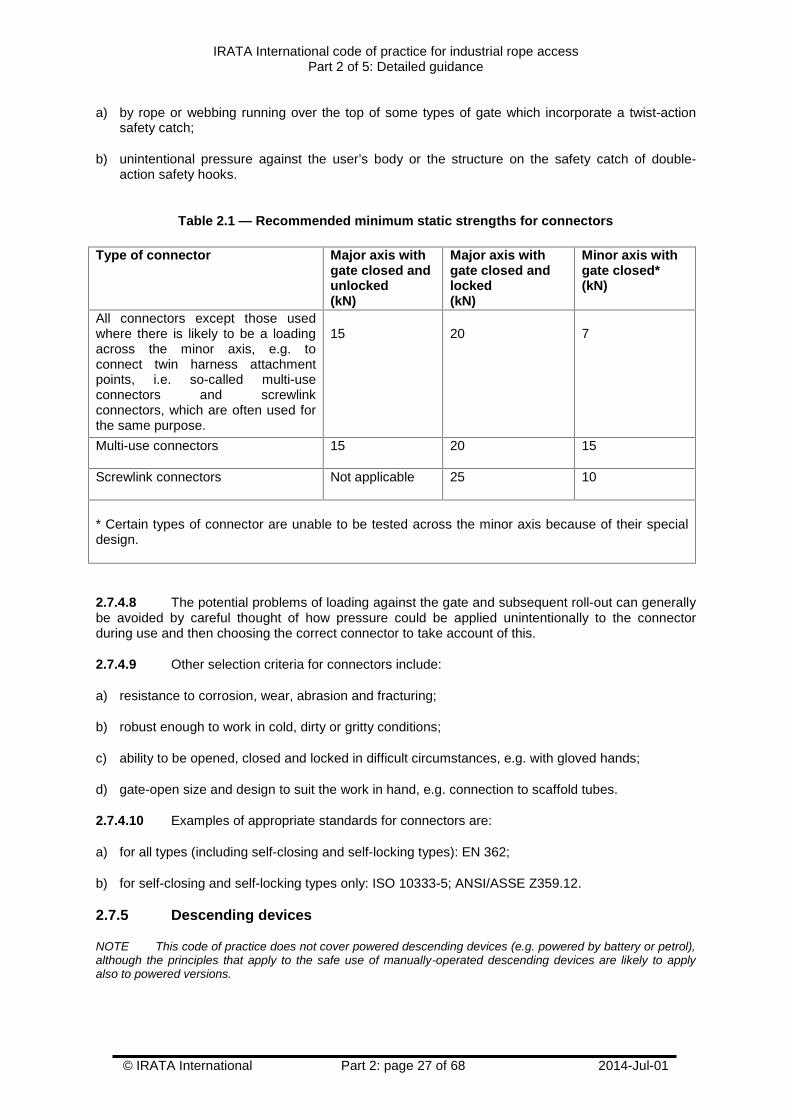
2.7.4.5 The minimum recommended static strengths for connectors are given in Table 2.1.
2.7.4.6 When selecting a connector, users should take account of its gate locking system andhow and where the connector is going to be used in the rope access system, to protect against roll-out. Roll-out is the result of pressure on the gate by another component connected to it, such as ananchor line device, a harness attachment point (especially if made from metal), a webbing lanyard, ananchor line or another connector. If the safety catch mechanism on the locking gate is actioned whilethis pressure is applied, it can cause the inadvertent opening of the connector gate and the roll-out(i.e. release) of the component from the connector.
2.7.4.7 In roll-out, the safety catch is usually accidentally tripped in one of two ways, dependingupon the type of locking gate. These are:
IRATA International code of practice for industrial rope accessPart 2 of 5: Detailed guidance
© IRATA International Part 2: page 27 of 68 2014-Jul-01
a) by rope or webbing running over the top of some types of gate which incorporate a twist-actionsafety catch;
b) unintentional pressure against the user’s body or the structure on the safety catch of double-action safety hooks.
Table 2.1 — Recommended minimum static strengths for connectors
Type of connector Major axis withgate closed andunlocked(kN)
Major axis withgate closed andlocked(kN)
Minor axis withgate closed*(kN)
All connectors except those usedwhere there is likely to be a loadingacross the minor axis, e.g. toconnect twin harness attachmentpoints, i.e. so-called multi-useconnectors and screwlinkconnectors, which are often used forthe same purpose.
15 20 7
Multi-use connectors 15 20 15
Screwlink connectors Not applicable 25 10
* Certain types of connector are unable to be tested across the minor axis because of their specialdesign.
2.7.4.8 The potential problems of loading against the gate and subsequent roll-out can generallybe avoided by careful thought of how pressure could be applied unintentionally to the connectorduring use and then choosing the correct connector to take account of this.
2.7.4.9 Other selection criteria for connectors include:
a) resistance to corrosion, wear, abrasion and fracturing;
b) robust enough to work in cold, dirty or gritty conditions;
c) ability to be opened, closed and locked in difficult circumstances, e.g. with gloved hands;
d) gate-open size and design to suit the work in hand, e.g. connection to scaffold tubes.
2.7.4.10 Examples of appropriate standards for connectors are:
a) for all types (including self-closing and self-locking types): EN 362;
b) for self-closing and self-locking types only: ISO 10333-5; ANSI/ASSE Z359.12.
2.7.5 Descending devices
NOTE This code of practice does not cover powered descending devices (e.g. powered by battery or petrol),although the principles that apply to the safe use of manually-operated descending devices are likely to applyalso to powered versions.
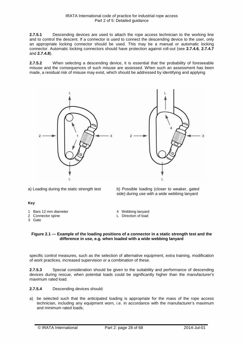
IRATA International code of practice for industrial rope accessPart 2 of 5: Detailed guidance
© IRATA International Part 2: page 28 of 68 2014-Jul-01
2.7.5.1 Descending devices are used to attach the rope access technician to the working lineand to control the descent. If a connector is used to connect the descending device to the user, onlyan appropriate locking connector should be used. This may be a manual or automatic lockingconnector. Automatic locking connectors should have protection against roll-out (see 2.7.4.6, 2.7.4.7and 2.7.4.8).
2.7.5.2 When selecting a descending device, it is essential that the probability of foreseeablemisuse and the consequences of such misuse are assessed. When such an assessment has beenmade, a residual risk of misuse may exist, which should be addressed by identifying and applying
a) Loading during the static strength test b) Possible loading (closer to weaker, gatedside) during use with a wide webbing lanyard
Key
1 Bars 12 mm diameter2 Connector spine3 Gate
4 Webbing lanyardL Direction of load
Figure 2.1 — Example of the loading positions of a connector in a static strength test and thedifference in use, e.g. when loaded with a wide webbing lanyard
specific control measures, such as the selection of alternative equipment, extra training, modificationof work practices, increased supervision or a combination of these.
2.7.5.3 Special consideration should be given to the suitability and performance of descendingdevices during rescue, when potential loads could be significantly higher than the manufacturer’smaximum rated load.
2.7.5.4 Descending devices should:
a) be selected such that the anticipated loading is appropriate for the mass of the rope accesstechnician, including any equipment worn, i.e. in accordance with the manufacturer’s maximumand minimum rated loads;
IRATA International code of practice for industrial rope accessPart 2 of 5: Detailed guidance
© IRATA International Part 2: page 29 of 68 2014-Jul-01
b) be appropriate for the length of the descent;
c) be capable of two-person loading and provide appropriate control over the speed of descent ifworkmate retrieval is going to be carried out using this device;
d) be suited to the prevailing environmental conditions, e.g. wet; icy; muddy; abrasive; corrosive;
e) be capable of giving the rope access technician appropriate control over the speed of descentand should not cause undue shock loads to the working line when braking;
f) automatically stop the descent if the rope access technician loses control, i.e. lock automaticallyin the hands-free mode (noting that it is common and acceptable for some minor creep of thedescending device along the anchor line to occur);
g) preferably fail to safe in all modes of operation, e.g. stop the descent automatically when grippedtoo tightly in panic (panic locking);
h) be simple to attach to the working line and have protection against incorrect attachment (e.g. viadesign; marking; warnings);
i) minimize damage, wear or twist to the working line;
j) have good heat dissipation characteristics (important on long descents or descents in highambient temperatures);
k) be compatible with the anchor line type and diameter;
l) not be capable of inadvertent detachment from the working line or becoming detached under anycircumstances while carrying a rope access technician's weight or while supporting the weight oftwo persons during a rescue.
2.7.5.5 Examples of appropriate standards for descending devices are:
a) EN 12841, Type C; ISO 22159.
b) For rescue only: EN 341.
2.7.6 Ascending devices
NOTE This code of practice does not cover powered ascending devices (e.g. powered by battery or petrol),although the principles that apply to the safe use of manually-operated ascending devices are likely to apply alsoto powered versions.
2.7.6.1 Ascending devices are attached to the working line and are used when the rope accesstechnician wishes to climb up it. Typically, there are two types of ascending device used in a ropeaccess system. The first type is used to connect the rope access technician directly to the working linevia the harness; the other type is attached to a foot loop to aid climbing and is also connected back tothe harness with a device lanyard to provide additional security.
2.7.6.2 Ascending devices should be of a type that cannot be detached accidentally from theworking line and should be chosen so that the risk of damage to the working line is minimized when inuse. Any dynamic loading should be avoided, as damage could result to either the ascending deviceor the working line.
2.7.6.3 Ascending devices should be chosen bearing in mind suitability for use in the prevailingenvironmental conditions, e.g. wet; muddy; icy; abrasive; corrosive.
2.7.6.4 Other selection criteria include:
IRATA International code of practice for industrial rope accessPart 2 of 5: Detailed guidance
© IRATA International Part 2: page 30 of 68 2014-Jul-01
a) simplicity of connection to the working line;
b) ease of adjustment when moving it up and down the working line;
c) effective grip on the working line;
d) resistance to abrasion, e.g. caused by dirty working lines;
e) minimal potential for damage to working lines under foreseeable loads, e.g. the sharpness ofteeth on the cam that grips the working line;
f) suitability for specific use, e.g. mounting on the chest when ascending;
g) ability to connect device lanyards and other devices.
2.7.6.5 An example of an appropriate standard for ascending devices is EN 12841, Type B.
2.7.7 Back-up devices
2.7.7.1 Back-up devices are used to attach the rope access technician to the safety line. This isnormally done by linking the back-up device to the user’s harness with a device lanyard. In the eventof a failure of the working line or loss of control by the rope access technician, back-up devices areintended to lock on to the safety line without causing catastrophic damage to the safety line and alsoto absorb the limited shock load that might occur.
2.7.7.2 When back-up devices are dynamically tested in accordance with standards, the testsonly represent a (vertical) free-fall. In certain circumstances, an uncontrolled descent may not be afree fall and the back-up device may not activate, e.g. if the user loses control of the descendingdevice during descent, if a fall is impeded by the structure or while descending at an angle other thanvertical. Back-up devices should be selected which are known to perform in such a way that anuncontrolled descent at all angles likely to be encountered during use would be prevented orminimized.
2.7.7.3 When used in accordance with the manufacturer’s instructions, the combination of back-up device, device lanyard, connectors and harness should be able to limit the force on the user to amaximum of 6.0 kN in the event of a working line failure.
NOTE 6 kN is a recognized threshold of injury.
2.7.7.4 It is recommended that back-up devices used are of a type that will not slip at a staticload of less than 2.5 kN to allow for two persons to be supported from it, which may be necessary in arescue situation.
2.7.7.5 When selecting a back-up device, it is essential that the probability of foreseeablemisuse and the consequences of such misuse are assessed. When such an assessment has beenmade, a residual risk of misuse may exist, which should be addressed by identifying and applyingspecific control measures, such as the selection of alternative equipment, extra training, modificationof work practices, increased supervision or a combination of these.
2.7.7.6 Special consideration should be given to the suitability and performance of back-updevices if they might be used during rescue, because potential loads could be significantly higher thanthe manufacturer’s maximum rated load.
2.7.7.7 Additional selection criteria for a back-up device include:
a) that the anticipated loading is appropriate for the mass of the rope access technician includingany equipment worn, i.e. in accordance with the manufacturer’s maximum rated load;
IRATA International code of practice for industrial rope accessPart 2 of 5: Detailed guidance
© IRATA International Part 2: page 31 of 68 2014-Jul-01
b) the suitability with regard to arresting the mass of the user, including any equipment worn orcarried;
c) the ability to keep any fall as short as possible;
d) that it does not cause catastrophic damage to the safety line when arresting a fall;
e) the suitability with regard to arresting a two-person load if workmate retrieval is going to be carriedout;
f) that it cannot be inadvertently disconnected from the safety line;
g) compatibility with the safety line type and diameter;
h) the ability to position the device anywhere on the safety line;
i) the suitability for the prevailing environmental conditions, e.g. wet; icy; dirty; abrasive; corrosive;
j) minimal manipulation required by the rope access technician;
k) preferably fail to safe in all modes of operation, e.g. prevent or arrest a fall even when gripped inpanic.
2.7.7.8 An example of an appropriate standard for back-up devices is EN 12841, Type A.
2.7.8 Lanyards and slings
2.7.8.1 General
2.7.8.1.1 Lanyards and slings are made in various forms and may be used for one or moreapplications. See Figure 2.2 for examples.
2.7.8.1.2 Some lanyards are used to provide a link between the user’s harness and certain anchorline devices, namely the foot ascender and the back-up device. In this code of practice, they arereferred to as device lanyards. Such lanyards are generally made from dynamic mountaineering ropeand are fitted with knotted terminations but are sometimes other types of energy absorber or energy-absorbing lanyard.
2.7.8.1.3 Other lanyards, also generally made from dynamic mountaineering rope and fitted withknotted terminations, are used to connect the rope access technician directly to an anchor point via aconnector. In this code of practice, they are known as anchor lanyards.
NOTE The lanyards described in 2.7.8.1.2 and 2.7.8.1.3, both of which are often commonly called cow’stails, have been separated into the two types (and renamed) because their specific use and requirements are orcan be different.
2.7.8.1.4 Slings are used to provide a link between structural anchors, e.g. a steel beam, oranchor devices, e.g. an eye bolt, to the attachment point for anchor lines (via a connector orconnectors), and are normally made from textile webbing, textile rope or wire rope and, sometimes,chain. These are known as anchor slings.
2.7.8.1.5 Lanyards and slings can be a fixed length or the length can be adjustable.
2.7.8.1.6 Webbing and rope made from man-made fibres used in the manufacture of lanyards andslings should be chosen so that any mechanical damage (e.g. abrasion) will become readily visiblewell before any loss of strength becomes significant. Stitching should be in a contrasting shade orcolour to that of the webbing to facilitate its inspection. The webbing, rope and stitching should beprotected against ultra-violet degradation, e.g. by the use of ultra-violet inhibitors and/or by aprotective covering.
IRATA International code of practice for industrial rope accessPart 2 of 5: Detailed guidance
© IRATA International Part 2: page 32 of 68 2014-Jul-01
2.7.8.1.7 The construction of webbing should be such that it does not unravel if one of the edges iscut. This applies to all components made from webbing.
2.7.8.1.8 Wire rope used in the manufacture of lanyards and slings should have a minimum staticstrength of 15 kN.
2.7.8.2 Device lanyards and anchor lanyards
2.7.8.2.1 Device lanyards and anchor lanyards should be able to withstand any dynamic forcesthat might be imposed upon them in times of emergency. Device lanyards and anchor lanyards madeof rope should have a performance at least equal to that of a “single” dynamic mountaineering rope,e.g. one conforming to European Standard EN 892 or the equivalent standard by the InternationalMountaineering and Climbing Federation (UIAA). Both these standards require the rope to haveenergy absorbing properties. Knots to be used for the terminations should be chosen for their energyabsorbing characteristics as well as their strength and should be tied only by competent persons. Theenergy absorption provided by the materials used in the construction of the lanyard is enhanced bythe knots used to terminate them and knotted terminations are therefore recommended. An exampleof a knot that is particularly good at absorbing energy is the scaffold knot (often referred to as a barrelknot), see Figure 2.3, which is frequently used in the end of the anchor lanyard. The knot in Figure2.3 shows the knot tied with two turns of the rope. There is a version that uses three turns. Bothversions are acceptable. It is good practice to re-tie, dress and set (i.e. hand tighten) knotsperiodically as part of the inspection process.
2.7.8.2.2 Device lanyards and anchor lanyards made from dynamic rope with knotted terminationsshould have a minimum static strength of 15 kN. The strength of the combination of chosen rope andknots should be confirmed, e.g. by testing the lanyard or by reference to information supplied by themanufacturer.
2.7.8.2.3 Other types of lanyard may be appropriate for use in rope access, e.g. lanyardsconforming to standards where the minimum static strength requirement is typically 22 kN and energyabsorption is not considered. For proprietary lanyards, the information supplied by the manufacturershould be consulted.
2.7.8.2.4 If an energy absorber is incorporated into the system (other than that provided by theenergy absorbing qualities of the material and termination knots used in the construction of the devicelanyard or anchor lanyard), it should conform to an appropriate standard for energy absorbers.
2.7.8.2.5 To minimize any fall potential and to aid manoeuvres in a rescue situation, it is importantthat the length of device lanyards is kept as short as possible and limited to the rope accesstechnician’s reach. This will vary from person to person.
2.7.8.2.6 Anchor lanyards are normally used in two lengths; the shortest typically when changingfrom one anchor line to another during descent, e.g. at a re-anchor, and the longest typically whenchanging from one anchor line to another during ascent, e.g. at a re-anchor. The lengths of theanchor lanyards should be as short as possible, i.e. no longer than is necessary to enable the ropeaccess technician to carry out the required manoeuvres. This is not only for maximum efficiency incarrying out the manoeuvres but also to minimize the potential for high impact forces in any fall thatmight occur.
2.7.8.3 Anchor slings
2.7.8.3.1 Anchor slings may be used where there are no suitable anchors to which the anchorlines can be attached directly. If made from man-made fibres, anchor slings should have sewn jointsand have a minimum static strength of 22 kN. Anchor slings made from wire rope should have aminimum static strength of 15 kN.
2.7.8.3.2 Where the included angle at the anchor point (the Y angle) is high and produces amultiplier effect (i.e. it increases the loading on the anchor sling), the extra forces that are produced
IRATA International code of practice for industrial rope accessPart 2 of 5: Detailed guidance
© IRATA International Part 2: page 33 of 68 2014-Jul-01
need to be taken into account. An example is when an anchor sling is wrapped around a lift-shafthousing. See Figure 2.4.
2.7.8.4 Selection criteria for device lanyards, anchor lanyards and anchor slings
Selection criteria for device lanyards, anchor lanyards and anchor slings include:
a) adequate strength;
b) energy absorbing characteristics, particularly for device lanyards and anchor lanyards;
c) compatible with the connectors being used, e.g. fits through the connector gate and does notbunch and distort unduly under load;
d) suitable length (adjustable or fixed);
e) suitable for attachment to the harness, where appropriate;
f) protected at wear points;
g) manufactured from appropriate materials for the task in hand, e.g. in some cases, steel cablemight be more suitable than rope or webbing, and for the work environment;
2.7.8.5 Other information on lanyards
2.7.8.5.1 Information on other types of lanyards is given in Part 3, Annex E.
2.7.8.5.2 Examples of appropriate standards for lanyards are:
a) EN 354; ISO 10333-2; ANSI/ASSE Z359.1;
b) For the construction of device lanyards and anchor lanyards: EN 892; UIAA-101.
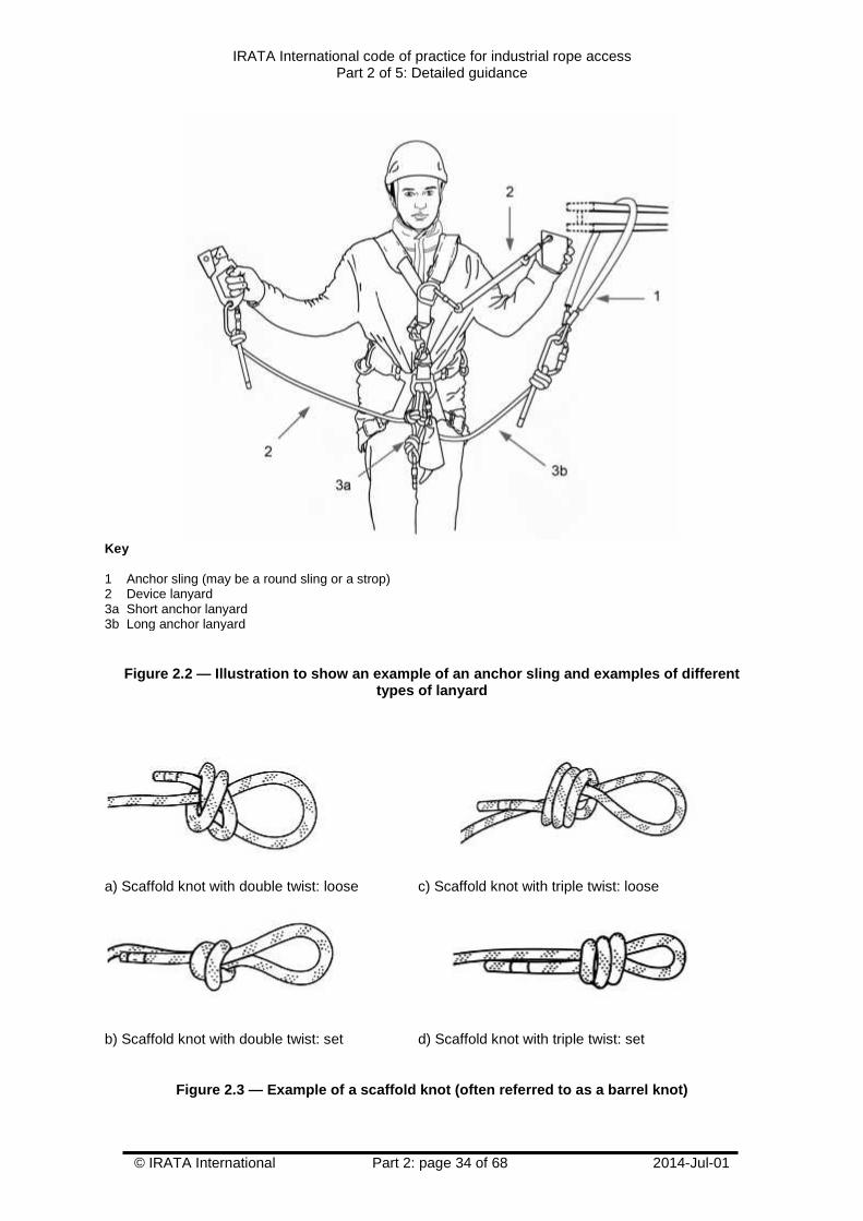
IRATA International code of practice for industrial rope accessPart 2 of 5: Detailed guidance
© IRATA International Part 2: page 34 of 68 2014-Jul-01
Key
1 Anchor sling (may be a round sling or a strop)2 Device lanyard3a Short anchor lanyard3b Long anchor lanyard
Figure 2.2 — Illustration to show an example of an anchor sling and examples of differenttypes of lanyard
a) Scaffold knot with double twist: loose c) Scaffold knot with triple twist: loose
b) Scaffold knot with double twist: set d) Scaffold knot with triple twist: set
Figure 2.3 — Example of a scaffold knot (often referred to as a barrel knot)
IRATA International code of practice for industrial rope accessPart 2 of 5: Detailed guidance
© IRATA International Part 2: page 35 of 68 2014-Jul-01
2.7.9 Anchors
NOTE The word anchor in this code of practice is used as a general term to describe, as a noun, a fitted orunfitted anchor device, or a structural anchor containing an anchor point and, as a verb, the act of connecting to afitted anchor device or structural anchor. Various terms relating to anchors are explained in Part 1 by way ofdefinitions and the accompanying Figure 1.1 in that part.
2.7.9.1 Anchors are used via their anchor point(s) for the attachment of anchor lines (i.e. theworking line and the safety line) to the structure or natural feature and also for other purposes, e.g. toreposition the anchor lines to avoid abrasion; to alter the direction of the anchor lines (deviationanchors); to maintain the anchor lines in their intended position; for the attachment of persons, eitherdirectly or indirectly. Anchors are fitted to anchorages at an anchorage point, i.e. the particular placeon the anchorage used for the attachment of the anchor device.
2.7.9.2 There are many different types of anchors. Examples are: eye bolts; anchor slings;specially designed rail anchor systems (which typically are permanently fitted around the perimeter ofthe roof of a building so that attachment can be made anywhere along them); ground anchor stakes(fixed into the ground); deadweight anchors; counterweight anchors; beam clamps. Examples ofanchorages are: structures made from steel beams; lift-shaft housings on tower blocks; soundconcrete and natural geological features such as a rock face or a tree. Anchors and anchoragesshould be unquestionably reliable.
2.7.9.3 It is essential that great care is taken when selecting anchor devices that they areappropriate to the situation in which they are fitted or to be fitted and used, e.g. that they are thecorrect type of anchor device for the given situation and that they are positioned and fitted correctly. Itis also essential that anchor devices are fitted, tested, inspected and used by competent persons andstrictly in accordance with manufacturer’s instructions.
2.7.9.4 The selection of anchors largely depends on whether anchors such as appropriateeyebolts could be fitted or are already in place and in the correct place, and whether opportunitiesexist to use other types of anchor, e.g. anchor slings fitted around the structure.
2.7.9.5 Anchors should be of an adequate strength, bearing in mind the mass of the userincluding any equipment worn or carried. See 2.11.2.6 to 2.11.2.8 for more advice.
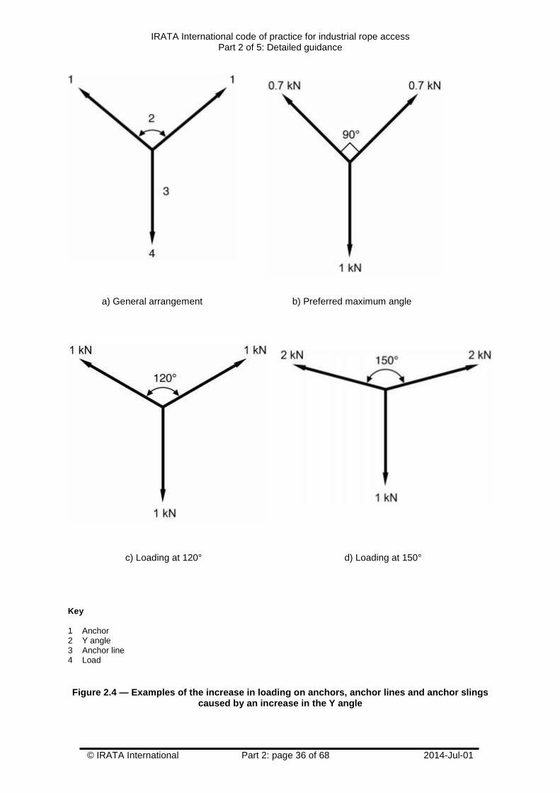
IRATA International code of practice for industrial rope accessPart 2 of 5: Detailed guidance
© IRATA International Part 2: page 36 of 68 2014-Jul-01
a) General arrangement b) Preferred maximum angle
c) Loading at 120° d) Loading at 150°
Key
1 Anchor2 Y angle3 Anchor line4 Load
Figure 2.4 — Examples of the increase in loading on anchors, anchor lines and anchor slingscaused by an increase in the Y angle
IRATA International code of practice for industrial rope accessPart 2 of 5: Detailed guidance
© IRATA International Part 2: page 37 of 68 2014-Jul-01
2.7.9.6 When selecting, fitting and using anchors, the principle of double protection (see 2.11.1)applies and, therefore, at least two anchors should always be used.
2.7.9.7 Rope access technicians and rescue services should be aware that additional anchorsmay be required to facilitate workmate retrieval. These should be of adequate strength for at least atwo-person load.
2.7.9.8 The subject of selection, fitting and use of anchors is complex. See 2.11.2 and Part 3,Annex F for further information.
2.7.9.9 Examples of appropriate standards for anchor devices are: BS 7883 and EN 795.
2.7.10 Protectors for anchor lines
NOTE This guidance on the protection of anchor lines against hazardous surfaces may also be applied incontext to the protection of lanyards and slings.
2.7.10.1 Wherever possible, anchor lines should be rigged so that they hang free and do notcome into contact with hazardous surfaces, e.g. edges or abrasive or hot surfaces, at any time duringthe rope access activity. Where this cannot be done, e.g. where it is not possible to arrange a naturalfree hang or use deviations or re-anchors, it is essential that anchor lines are suitably protectedagainst the hazard. This can be achieved in various ways, e.g. by the use of edge protectors such asrollers; metal edge plates; edge padding, or by anchor line protectors such as a textile sheath whichencapsulates the anchor line, or by a combination of both types of protector. See 2.11.3 and Annex Pfor more information on the protection of anchor lines.
2.7.10.2 Selection criteria for edge protectors and anchor line protectors include:
a) suitability for the particular site conditions, e.g. provides adequate protection against cutting,abrasion, excessive heat or chemical contamination;
b) suitability for compatibility with anchor line type, e.g. construction; diameter; number of anchorlines;
c) a features to allow them to be tied off (if required) to keep the edge protectors and anchor lineprotectors in their intended place and to maintain the anchor line(s) in position within or on them;
d) a design that allows the rope access technician to place and to pass the edge protector or anchorline protector;
e) the ability to inspect the anchor line(s) while located in or on the edge protector or anchor lineprotector.
NOTE There are no known standards for edge protectors and anchor line protectors.
2.7.11 Work seats
2.7.11.1 When there is a need for rope access technicians to remain suspended in one place formore than a few minutes, support additional to that provided by the harness is recommended. Theuse of even a simple work seat can enhance the comfort, health and safety of a rope accesstechnician, possibly including a reduction in the risk of experiencing the symptoms of suspensionintolerance. For more information on suspension intolerance, see Part 3, Annex G.
2.7.11.2 The work seat should be fitted in such a way that the harness remains the primarymeans of attachment to the anchor lines, should the work seat fail.
NOTE There are no known appropriate standards for work seats.
IRATA International code of practice for industrial rope accessPart 2 of 5: Detailed guidance
© IRATA International Part 2: page 38 of 68 2014-Jul-01
2.7.12 Helmets
2.7.12.1 Rope access technicians should wear protective helmets that are suitable for the type ofwork being undertaken. Helmets that conform to standards for either mountaineering or industrial usemight be suitable. Some industrial helmets might not be suitable because they might not havesufficient side impact protection or strong enough chinstraps.
2.7.12.2 Chinstraps on helmets used in rope access work should prevent the helmet from comingoff the head. This is typically achieved by the incorporation of “Y” shaped straps in the design of thehelmet. Helmets should always be used with the chinstrap fastened.
2.7.12.3 Selection criteria for helmets include:
a) light weight, but without compromising safety;
b) good fit, i.e. adjustable to the wearer’s head size;
c) the ability to mount ancillary equipment such as communications equipment; headlamp; earprotectors; visors;
d) unrestricted vision (downwards, sideways and upwards);
e) good ventilation, particularly in hot climates.
2.7.12.4 Examples of appropriate standards for helmets (when the caveats in the notes are takeninto account) are:
a) Industrial: EN 397; EN 14052;
b) Mountaineering: EN 12492.
NOTE 1 Users should check carefully the performance of industrial helmets conforming to European StandardEN 397 as they might not have the all the performance requirements for the safety of rope access technicians,e.g. front, side and rear energy absorption capacity (not specified in EN 397); appropriate chinstrap and fasteningarrangement; low temperature use and ventilation (optional in EN 397).
NOTE 2 Helmets utilizing expanded polystyrene shells (common in helmets conforming to European StandardEN 12492) are unlikely to withstand the rigours of industrial use and, therefore, are generally not recommended.
2.7.13 Pulleys
2.7.13.1 Pulleys are used in a variety of rope access manoeuvres. They should be appropriate fortheir intended use, i.e. by personnel, and be suitably load-rated. Rope access technicians should beaware of the possible increase of loadings on anchors in some rigging situations.
2.7.13.2 Examples of appropriate standards for pulleys are: EN 12278; UIAA 127.
2.7.14 Clothing and protective equipment
2.7.14.1 Rope access technicians need to be appropriately dressed and equipped for the worksituation and conditions.
2.7.14.2 It can be difficult for rope access technicians to avoid exposure to changing climaticconditions or harmful substances when working at a height. Employers should assess carefully whatthe most appropriate clothing would be to guard against such hazards. This protective clothing shouldbe provided and measures taken to ensure that it is worn.
IRATA International code of practice for industrial rope accessPart 2 of 5: Detailed guidance
© IRATA International Part 2: page 39 of 68 2014-Jul-01
2.7.14.3 Rope access technicians should wear the following:
a) protective clothing (e.g. overalls) that have no loose parts, which might become caught in anymoving equipment. Pockets should be fitted with zip or touch-and-close type fastenings ratherthan buttons. Waterproof and/or windproof clothing should be provided where necessary. Flameproof or flame resistant overalls should be provided for welding, burning or cutting work;
b) suitable footwear, which fits well, provides a good grip and gives an adequate level of protectionfor the task being undertaken. Special protective boots may be needed when grit blasting or ultra-high pressure water-jetting to prevent injury.
2.7.14.4 If equipment is to be fitted to the user, it is important that it is comfortable to wear and fitsthe wearer properly when correctly adjusted. This should be checked in a safe place, before workcommences. Such equipment should not significantly hinder the wearer from carrying out their dutiesor from properly operating the anchor line devices.
2.7.14.5 The following protective items might also be required:
a) gloves, to protect against cold weather, injury or other harmful effects;
b) eye protection, where debris is being cleared or material is being removed, or where drilling,blasting or percussion operations are being undertaken. Eye protection is usually also required ifchemicals are being sprayed or painted, which could cause irritation or injury to the eyes. IRATAInternational work and safety statistics have shown numerous lost time incidents due to eyeinjury, including where visors or safety glasses have been worn. It is likely that the wearing ofgoggles would have prevented these injuries;
c) respiratory protective equipment, where there is a risk of inhalation of harmful chemicals or dust.Many building chemicals are liable to be harmful, particularly in a situation where a rope accesstechnician is unable to get quickly to a source of fresh water to dilute or wash the chemical away;
d) hearing protectors, when noise levels could cause a risk of hearing loss to rope accesstechnicians;
e) buoyancy or life jackets, when working over water. These should be of a type capable of beingsecured to the wearer so that they cannot accidentally come loose in the event of a fall. Inaddition, they should not obstruct the wearer or prevent the efficient operation of the anchor linedevices;
f) protection against sunburn, e.g. by the use of a sunscreen.
2.7.14.6 Any variation in normal procedures in the use of protective equipment on the worksite(e.g. lifejackets; eye protection; safety footwear; helmet), for whatever reason, should first be clearedwith the site management.
IRATA International code of practice for industrial rope accessPart 2 of 5: Detailed guidance
© IRATA International Part 2: page 40 of 68 2014-Jul-01
2.8 Marking and traceability
2.8.1 Load-bearing rope access equipment should carry sufficient marking:
a) to enable identification of the manufacturer and, where appropriate, the model/type/class ofequipment;
b) so that it can be easily associated with its respective documentation, e.g. certificates ofconformity, examination and inspection records;
c) to allow further traceability, e.g. to enable the isolation of a rogue batch of components;
d) to meet any requirements of legislation, e.g. national regulations.
This is achieved typically by the use of an identifier, e.g. a manufacturer’s serial number, or by batchmarking with additional forms of identification, e.g. a coding system.
2.8.2 Equipment that does not have adequate marking made by the manufacturer should beindelibly marked in a manner that does not affect its integrity, e.g. by the use of: plastic or metal tags,which can be stamped with data and fixed with cable ties; a suitable paint; a suitable adhesive tape.(The paint or adhesive should be of a type that is not capable of damaging the component beingmarked and should be applied and positioned so that it cannot obscure any defect.)
2.8.3 Equipment such as ropes and harnesses could be indelibly marked by various methods,e.g. by marking their identification on a tape, which is then fixed in place by a heat-shrunk clear plasticcover. Lengths cut off a main rope could have the identity transferred to them sequentially; e.g. apiece of rope cut off a main rope numbered A1 could be numbered A1/1, A1/2 etc. Connectors areoften colour coded to indicate an in-date inspection period, as older items often lack uniqueidentification and marking by the user can be difficult.
2.8.4 Metal items should not be marked by stamping, unless by agreement with themanufacturer. This is because stamping can cause the potential for cracking of certain metals undercertain conditions and, therefore, great care should be taken if this method of marking is chosen. Themarking of metal items by engraving should only be carried out in such a way that it does not affectthe integrity of the equipment, e.g. by marking in a non-safety-critical area of a component. It shouldbe noted that stamping and engraving may damage any applied corrosion-resistant surface, e.g.electroplating, and it is recommended that steps be taken to avoid this potential for damage, e.g. bycoating the indentations made by the stamping or engraving with paint.
2.8.5 Helmets should not be marked with adhesive labels or adhesive tape without permissionfrom the manufacturer, as some solvents used in adhesives can adversely affect the helmet’sperformance. Care should be taken that equipment made from webbing or rope is not marked withdamaging chemicals, e.g. inks, or products containing potentially harmful adhesives.
2.8.6 The identification and traceability details should be matched to records of use to help in theequipment’s care and maintenance. This also applies to hired or sub-contractors’ equipment.

IRATA International code of practice for industrial rope accessPart 2 of 5: Detailed guidance
© IRATA International Part 2: page 41 of 68 2014-Jul-01
This page is intentionally blank
IRATA International code of practice for industrial rope accessPart 2 of 5: Detailed guidance
© IRATA International Part 2: page 42 of 68 2014-Jul-01
2.9 Records
2.9.1 Records should be kept to track the use of individual pieces of equipment, its inspectionand its maintenance. These should include at least the following:
a) the name of the manufacturer;
b) the name of the model, type or class of the equipment, as appropriate;
c) the purchase date;
d) the date of entry into service;
e) the obsolescence date;
f) the manufacturer’s serial number or batch marking to enable traceability, e.g. to the productionstage;
g) the information supplied by the manufacturer, including instructions for use;
h) the safe working load, working load limit or maximum and minimum rated loads, whichever isprovided;
i) any certificate of conformity, e.g. to a standard;
j) the duration of active use, e.g. number of days;
k) current location and where it is stored normally;
l) any arduous conditions in which the equipment has been used, e.g. exposure to chemicals;abrasion; heavy grit; any unusual loads or damage imposed;
m) any workmate retrieval carried out;
n) the date and result of inspections, the type of inspection carried out (detailed or interim) and thedate the next inspection is due;
o) details of servicing, repairs or modifications.
Such information could help to determine when to take an item out of service.
2.9.2 Records of inspections should be kept at least until a subsequent inspection is carried outand copies of inspection records should be made available for viewing by relevant persons (see Part3, Annex N). Local legislation may determine the specific retention period for records.
IRATA International code of practice for industrial rope accessPart 2 of 5: Detailed guidance
© IRATA International Part 2: page 43 of 68 2014-Jul-01
This page is intentionally blank
IRATA International code of practice for industrial rope accessPart 2 of 5: Detailed guidance
© IRATA International Part 2: page 44 of 68 2014-Jul-01
2.10 Inspection, care and maintenance of equipment
2.10.1 General procedures
2.10.1.1 The manufacturer should always provide information on the inspection, care andmaintenance of equipment and this should be strictly followed. This section details good practice forrope access purposes.
2.10.1.2 Procedures should be established by employers for the inspection and maintenance ofequipment and the method by which this is to be recorded. The inspection and maintenance ofequipment should only be carried out by competent persons. Inspection and maintenance may becarried out by the manufacturer’s representative or specialist third parties if required.
2.10.1.3 There are three types of inspection to which all rope access equipment should besubjected, to decide if the equipment can continue to be used or if it should be removed from use anddestroyed. These are the pre-use check, the detailed inspection and, in certain circumstances, theinterim inspection. Any item showing any defect during these inspections should be withdrawn fromservice, immediately if possible.
2.10.1.4 It is essential that all load-bearing equipment is given a visual and tactile inspection bythe user before each use to ensure that it is in a safe condition and operates correctly. In addition,there should be a formal process for detailed inspection of equipment by a competent person orpersons. For an inspection checklist, see Part 3, Annex H.
2.10.1.4.1 Pre-use check
The pre-use check consists of a visual and tactile inspection, which should be carried out before firstuse each day. Formal documentation for daily inspections should not be necessary, although someusers may wish to include a checklist in daily inspection documentation. It is advisable to continue tomonitor the condition of equipment throughout the duration of the task and not just at the start of theday.
2.10.1.4.2 Detailed inspection
There should be a formal inspection procedure to ensure that equipment is thoroughly inspected by acompetent person before equipment is used for the first time and then at intervals not exceedingsix months, or in accordance with a written inspection scheme. This should be carried out inaccordance with any manufacturer’s guidance. The results of detailed inspections should berecorded. For a recommended list of information to be recorded following a detailed inspection, seePart 3, Annex I.
2.10.1.4.3 Interim inspection
Where equipment is used in arduous conditions or exceptional events liable to jeopardize safety haveoccurred, further inspections (called interim inspections) should be carried out. These are inspectionsin addition to the detailed inspection and the normal pre-use check. They should be carried out by acompetent person at intervals determined by the risk assessment. Suitable times for interiminspections can be decided by taking into account factors such as whether items are subject to highlevels of wear and tear (e.g. unusual loadings or a gritty environment) or contamination (e.g. in achemical atmosphere). Interim inspections should be recorded.
2.10.1.5 It is essential that the person carrying out a detailed or interim inspection has the authorityto discard equipment and is sufficiently competent, independent and impartial to allow objectivedecisions to be made. A competent person may exist within a rope access company, or could be aspecialist supplier, manufacturer or a specialist repair organization. Companies should detail theirarrangements for nominating the competent person or persons in their management system.
IRATA International code of practice for industrial rope accessPart 2 of 5: Detailed guidance
© IRATA International Part 2: page 45 of 68 2014-Jul-01
2.10.1.6 Should there ever be any doubt about the continued serviceability of an item ofequipment, the matter should be referred to a competent person or the equipment should bequarantined or discarded. It is good practice to try to establish how the damage occurred so that it canbe prevented from happening again.
2.10.1.7 Equipment subjected to a high impact force, e.g. in a fall or by a load being dropped onto it, should be withdrawn immediately from use.
2.10.1.8 It is recommended that rope access equipment, indeed any personal fall protectionequipment, is not subjected to proof load testing by the user.
2.10.2 Equipment manufactured from man-made fibres
2.10.2.1 All equipment manufactured from man-made fibres, e.g. ropes; webbing; harnesses;lanyards, should be chosen, used and inspected with particular care as it is susceptible to varyingtypes and amount of damage, some of it not very easy to identify.
2.10.2.2 Man-made fibres used in equipment for rope access are usually polyamide or polyester.Materials other than polyamide or polyester might be more suitable for certain working conditions butall have their limitations. Examples are:
a) high performance polyethylene or high tenacity polypropylene, which might be more suitablewhere there is severe chemical pollution. However, polyethylene and polypropylene have muchlower melting temperatures than polyamide or polyester and are more easily affected by frictionalheat (dangerous softening of polypropylene occurs at temperatures as low as 80 °C);
b) aramid, which is resistant to high temperatures, might be more suitable where equipment with ahigh melting point is required. However, aramid has low resistance to abrasion, repeated bendingand to ultraviolet light.
Users should, therefore, take account of these properties, including the melting point, resistance toabrasion and flexing, resistance to ultraviolet light and chemicals, and the elongation characteristics,when selecting, using and inspecting such equipment.
2.10.2.3 Ultraviolet light (UV) degrades and thus weakens most, if not all, man-made fibres. UV isemitted by sunlight, fluorescent light, which also contains ultraviolet light, and all types of electric-arcwelding. The normal way to provide protection is by the inclusion of UV inhibitors at the fibreproduction stage but there are other possibilities, such as the type and colour of any dye used or theuse of a protective covering. It is recommended that confirmation is obtained from the manufacturerthat all man-made fibres in their equipment, including sewing threads, contain sufficient ultravioletinhibitor for the conditions in which the equipment is to be used (ultraviolet light levels vary in intensitydependent upon location) and that the fibres have not been subjected to any dyeing or finishingprocess that could have detrimentally affected the level of protection. As ultraviolet inhibitors do notoffer total protection, even man-made fibres that include them should not be exposed unnecessarily tosunlight, fluorescent light, and the light emitted by all types of electric-arc welding. It should be notedthat many equipment standards for personal fall protection equipment do not address explicitly thepotential for degradation by UV (or abrasion) during use of the product, relying instead on its strengthincluding a safety factor when new. There is no guarantee that this approach will give sufficientprotection against UV (or abrasion).
2.10.2.4 Man-made fibres react in different ways when exposed to different chemicals at differentconcentrations and temperatures. For example, polyamide has good resistance to some alkalis, butthe resistance is not total, does not apply to all alkalis and not at all concentrations or at alltemperatures. Similar limitations apply to polyester, which has good resistance to some acids. Usersshould be aware of the chemicals present in the work environment and the potential effect on theirequipment when selecting, using and inspecting it. For the properties of some man-made fibres usedin the manufacture of rope access equipment, see Part 3, Annex J.
IRATA International code of practice for industrial rope accessPart 2 of 5: Detailed guidance
© IRATA International Part 2: page 46 of 68 2014-Jul-01
2.10.2.5 The performance of some materials changes when they become wet. An example ispolyamide fibre, which, when wet, loses between 10 % and 20 % of its strength. Fortunately, the lossis temporary and the strength is recovered when the material dries. In drop tests on dynamic rope thathad been soaked in water for different periods, the impact loads increased by up to 22 % above thosefor dry ropes (typically by between 8 % and 12 %). Although the use of equipment made of webbingor rope in wet conditions does not usually need to be a cause for concern, it would be sensible to takeextra care, particularly if the equipment is being used in conditions where it is subjected to loads closeto its maximum rated load.
2.10.2.6 Components made from man-made fibres should be checked carefully before beingstored and during the pre-use check by passing them through the hands to combine a tactile andvisual examination. Kernmantel ropes should be checked to see that the sheath has not been cut andby feeling the rope for any damage to the core. Cable-laid ropes should be carefully twisted open atintervals along their length to inspect for internal damage. Harnesses and webbing should be checkedfor cuts, abrasions, broken stitches and undue stretching.
2.10.2.7 Man-made fibres deteriorate slowly with age regardless of use and this ageing isaccelerated by heavy and dynamic loadings. However, the most common cause of strength loss inequipment made from man-made fibres is through abrasion (either by grit working into the strands ofwebbing or rope or by chafing against sharp or rough edges) or by other damage, such as cuts.
2.10.2.8 Equipment made from man-made fibres should be carefully and regularly inspected forsigns of abrasion. This applies to both external abrasion and internal abrasion. External abrasion iseasy to see but sometimes it is difficult to determine the extent of its detrimental effect. Internalabrasion is more difficult to spot but can often be substantial, particularly if grit has penetrated theouter surface. All levels of abrasion lower the strength of this equipment: as a general rule, the greaterthe abrasion the greater the loss of strength. The effects of UV degradation and abrasion combinedweaken the materials even further.
2.10.2.9 To minimize grit content, or simply to keep the product clean, soiled items should bewashed in clean water (maximum temperature 40 ºC) with pure soap or a mild detergent (within a pHrange of 5.5 to 8.5), after which they should be thoroughly rinsed in cold, clean water. The use of awashing machine is permissible but it is recommended that the equipment be placed in a suitable bagto protect against mechanical damage. Wet equipment should be dried naturally in a warm room awayfrom direct heat.
2.10.2.10 Internal abrasion can also occur without any ingress of grit, simply by the action of thefibres rubbing together when flexing during normal use. For most textile materials, this is a slowprocess and is not significant. An exception is material made from aramid, which is very susceptible tothis type of damage.
2.10.2.11 Equipment made from man-made fibres that have been in contact with rust should bewashed. Such equipment with permanent rust marks should be regarded as suspect and scrapped.Tests have indicated that rust may have a weakening effect on polyamides.
2.10.2.12 Any component with a cut or substantial abrasion should be scrapped. The presence of afew small loops of fibres pulled up from the surface (plucks) is not a cause for concern. However,plucks can be susceptible to snagging, thereby causing additional damage, and should be kept underobservation.
2.10.2.13 It is essential to avoid contact with any chemical that could affect the performance of theequipment. These include all acids and strong caustic substances (e.g. vehicle battery acid, bleach,drilling chemicals and products of combustion). The equipment should be withdrawn from service ifcontact does occur or is even suspected. Vigilance is necessary as contamination can come fromunusual sources. In a climbing fatality in France, the effect of formic acid emitted by ants was cited aspart of the reason for the failure of the climbing rope.
2.10.2.14 Deterioration in ropes from contact with chemicals, or from mechanical damage, is oftenlocalized and not obvious, and can be missed during inspection. Chemical deterioration is often not
IRATA International code of practice for industrial rope accessPart 2 of 5: Detailed guidance
© IRATA International Part 2: page 47 of 68 2014-Jul-01
detectable visually until the component starts to fall apart. The safest course of action is to scrap anycomponent about which there is any doubt. Proof load testing should not be carried out oncomponents made from man-made fibres.
2.10.2.15 Anchor lines, webbing or harnesses which have glazed or fused areas could havesuffered excessively high temperatures and are suspect. If the fibres appear powdery or if there arechanges in colour in a dyed component, this can indicate severe internal wear or contact with acids orother damaging chemicals, or it can indicate ultra-violet degradation. Swellings or distortion in a ropecan be a sign of damage to the core fibres or of movement of the core within the sheath. Cuts, chafes,plucking and other mechanical damage weaken ropes and webbing, the degree of weakening beingdirectly related to the severity of the damage. Loosening or excessive breaks in the yarns couldindicate internal wear or cuts. Advice should be sought from the supplier or manufacturer, but if thereis any doubt as to the condition of the equipment, it should be scrapped.
2.10.2.16 Most man-made fibres are affected by high temperatures and begin to change theircharacter, and thus their performance, at temperatures exceeding 50 C. Therefore, care should betaken to protect against this. (The rear parcel shelf of a car in hot weather, for example, can exceedthis temperature.)
2.10.2.17 Equipment made from man-made fibres should not normally be dyed, except by themanufacturer. Many dyes contain acids or require the use of acids to fix the colour permanently to thefibres, which could cause strength losses of up to 15 %.
2.10.3 Metal equipment
2.10.3.1 Most metal equipment, e.g. connectors; descending devices; ascending devices, is madeof steel or of aluminium alloys, although other metals, such as titanium, are sometimes used.Aluminium alloys and most steels, with the exception of stainless steel, all look the same. However,the performance of these metals can vary greatly, particularly in terms of their corrosion resistance. Itis essential, therefore, that the user knows from what the equipment is made, so that relevantprecautions can be taken.
2.10.3.2 Equipment made from aluminium alloys sometimes has a polished surface finish, butusually it is anodized. Anodizing provides a thin electrochemical coating, which is harder than thebase material. This coating protects the base metal against corrosion and also, to a small extent,against wear.
2.10.3.3 The various aluminium alloys used in rope access equipment have differentcharacteristics. Generally, the stronger the alloy, the more susceptible it is to corrosion, so greatercare in use, maintenance and inspection is required. Aluminium alloys are particularly susceptible tocorrosion when in contact with seawater.
2.10.3.4 Contact between different metals can cause galvanic corrosion to occur, especially whenwet, as a result of electrolytic action. This is one reason why equipment should not be stored wet (see2.10.7). Galvanic corrosion can affect many metals, including aluminium and some stainless steelsand can cause the rapid destruction of protective coatings such as zinc. Long term contact ofdissimilar metals (e.g. copper and aluminium) should be avoided, especially in wet conditions and, inparticular, in a marine environment.
2.10.3.5 Some metals that are under tensile stress and in a corrosive environment can developsurface cracks. This is known as stress corrosion cracking. It is time dependent and can take manymonths to become apparent. This highlights why the need for regular inspection of equipment is soimportant.
2.10.3.6 Metal items such as rings, buckles on harnesses, connectors and descending devicesrequire checking to ensure that hinges etc. work smoothly, bolts and rivets are tight and to look forsigns of wear, cracks, deformation or other damage. They should be kept clean and, when dry,moving parts should be lubricated using a light oil or silicone grease. Lubrication should be avoided inareas that might come into contact with webbing fastening straps (for example, the slide bar of a
IRATA International code of practice for industrial rope accessPart 2 of 5: Detailed guidance
© IRATA International Part 2: page 48 of 68 2014-Jul-01
harness buckle), ropes, slings, etc. because it could affect the proper functioning of any fasteningarrangement. Any item showing any defect should be taken out of service.
2.10.3.7 Equipment made totally from metal can be cleaned by submerging in clean, hot watercontaining detergent or soap for a few minutes. High-pressure steam cleaners should not be usedbecause the temperature could exceed the recommended maximum of 100 ºC. Seawater should notbe used for cleaning. After cleaning, the equipment should be thoroughly rinsed in clean, cold waterand then dried naturally away from direct heat.
2.10.3.8 Some chemical products used in building work can cause excessive corrosion to itemsmade of aluminium alloys. Advice on dealing with this should be obtained from the productmanufacturer.
2.10.4 Protective helmets
The shells of protective helmets should be checked for cracks, deformation, heavy abrasion, scoringor other damage. The chinstraps and cradles should be checked for wear, as should the security ofany attachment points between different elements, such as sewn or riveted areas. Any helmetshowing any defect should be taken out of service. Helmets made from polycarbonate should nothave stickers placed on them unless it has been confirmed by the manufacturer that it is safe to doso. This is because the solvent used in the adhesive of some stickers can detrimentally affect thepolycarbonate.
2.10.5 Disinfection of equipment
It may be considered necessary to disinfect equipment, for example after working in a sewer, althoughnormally cleaning as described in 2.10.2.9 or 2.10.3.7 is sufficient. There are two things to considerwhen choosing a disinfectant: its effectiveness in combating disease and whether or not there will beany adverse effect on the equipment after one or several disinfections. Advice should be sought onthese two points from the manufacturer or supplier of the equipment before carrying out anydisinfection. After disinfection, the equipment should be rinsed thoroughly in clean, cold water andthen dried naturally in a warm room away from direct heat.
2.10.6 Equipment exposed to a marine environment
If used in a marine environment, equipment should be cleaned by prolonged immersion in clean, coldfresh water, then dried naturally in a warm room away from direct heat and inspected before storage.
2.10.7 Storage
After any necessary cleaning and drying, equipment should be stored unpacked in a cool, dry, darkplace in a chemically neutral environment away from excessive heat or heat sources, high humidity,sharp edges, corrosives, unauthorized access, rodents, ants (which emit formic acid) or other possiblecauses of damage. Equipment should not be stored wet because of the possibility of fungal attack orcorrosion.
2.10.8 Equipment withdrawn from service
2.10.8.1 It is important that there is a quarantine procedure for ensuring defective or suspectequipment that has been withdrawn from service does not get back into service without the inspectionand approval of a competent person.
2.10.8.2 Equipment found to be defective at inspection, or if its serviceability is compromised or indoubt, should be withdrawn from service and referred for further inspection or repair. Such equipmentshould be marked as not fit for service and, if not repairable, should be destroyed to ensure it cannotbe used again. Records should be updated immediately.
IRATA International code of practice for industrial rope accessPart 2 of 5: Detailed guidance
© IRATA International Part 2: page 49 of 68 2014-Jul-01
2.10.9 Lifespan
2.10.9.1 It is very difficult to know by how much equipment is deteriorating (particularly equipmentmade from man-made fibres), without testing to destruction, which rather defeats the objective.Therefore, it is advisable to set a period after which such equipment should no longer be used. Thisperiod is known as the lifespan. The information supplied by the manufacturer for the equipmentshould be referred to when deciding on the lifespan. It is also important that a history is kept of theuse of equipment, which should ideally log the conditions in which it was used, as this could be usefulin any review of the lifespan set for the equipment.
2.10.9.2 Some equipment is given a lifespan (e.g. an obsolescence date) by the manufacturer.Equipment that has reached such a limit and has not already been rejected for another reason shouldbe withdrawn from service and not used again, unless or until confirmed by a competent person, inwriting, that it is acceptable to do so. Records should be updated immediately.
2.10.10 Alterations to equipment
Equipment should not be altered without the prior approval of the manufacturer or supplier becauseits performance might be affected.
IRATA International code of practice for industrial rope accessPart 2 of 5: Detailed guidance
© IRATA International Part 2: page 50 of 68 2014-Jul-01
2.11 Primary rope access work methods
2.11.1 Double protection
2.11.1.1 A rope access system actually consists of an access (sub) system and a back-up (sub)system, which are used together. The access system provides the primary support for access, egressand work positioning. It comprises a working line and descending and ascending devices, which areattached to the working line and which are always connected to the rope access technician’s harness.The back-up system provides security additional to that provided by the access system, e.g. shouldthere be a failure of the access system. The back-up system comprises a safety line and a back-updevice, which is attached to the safety line and which is always connected to the rope accesstechnician’s harness. This system of double protection, which was developed by IRATA International,is one of the key elements of a safe rope access system.
NOTE For an example of a typical method of ascending and descending using IRATA International ropeaccess techniques, see Part 3, Annex K.
2.11.1.2 The working line and the safety line are known collectively as anchor lines. Each anchorline should be attached to its own anchor point. The working line and the safety line are normallyconnected to each other for added security, as well as allowing the anchor lines to be positionedbetween the anchors. Load sharing between anchors reduces the load on each one. This minimizesthe likelihood of failure of either anchor but, in the unlikely event of a failure of one of them, therewould only be a minimal impact force on the second anchor. A single element of a structure, (e.g.structural steelwork), a natural geological feature or a tree might have adequate strength to provide aplace for anchor points for both the working line and the safety line. This should be verified by acompetent person. Rope access safety supervisors are responsible for checking that anchor lines arecorrectly rigged. See Figure 2.5.
2.11.1.3 The principle of double protection also applies to the attachment of rope accesstechnicians via their anchor line devices to the working line and safety line and to any anchors by theiranchor lanyards. For example, descending devices and back-up devices should be fixed to the ropeaccess technician's harness with separate connectors, in accordance with the information supplied bythe manufacturer. (It is not necessary to wear two harnesses).
2.11.1.4 Rope access technicians normally descend the working line by means of the descendingdevice, with the back-up device attached to the safety line. During ascent, ascending devices areattached to the working line, with the back-up device attached to the safety line. During both ascentand descent, the back-up device should be positioned so that the distance of any potential fall and itsconsequences are minimized. The system can be modified to become a top rope protection, whereparticular supervision or care of the rope access technician is required.
NOTE Sometimes, rope access methods are used in conjunction with conventional suspended accessequipment. In such cases, the principle of double protection still applies to the rope access work. The anchors forrope access should be independent of the anchors for the conventional suspended access equipment. For thesafety requirements for work on conventional suspended access equipment, reference should be made to theappropriate standards.
2.11.1.5 When carrying out rope access manoeuvres, e.g. passing a re-anchor; passing a knot,the action should be carried out in such a way that at least two independent points of attachment aremaintained at all times.
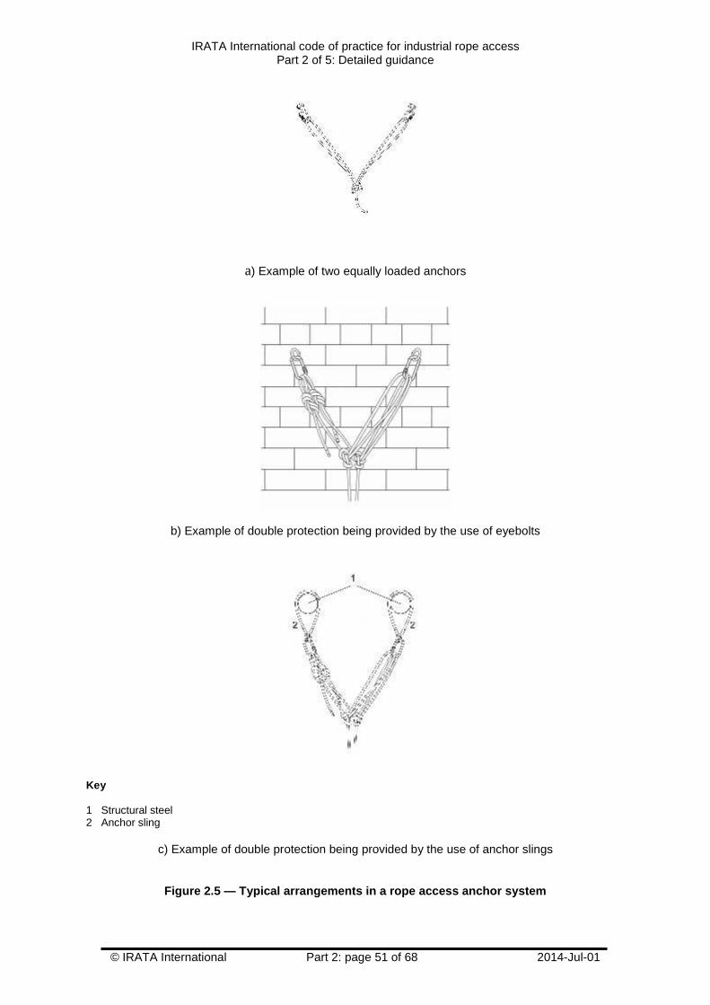
IRATA International code of practice for industrial rope accessPart 2 of 5: Detailed guidance
© IRATA International Part 2: page 51 of 68 2014-Jul-01
a) Example of two equally loaded anchors
b) Example of double protection being provided by the use of eyebolts
Key
1 Structural steel2 Anchor sling
c) Example of double protection being provided by the use of anchor slings
Figure 2.5 — Typical arrangements in a rope access anchor system
IRATA International code of practice for industrial rope accessPart 2 of 5: Detailed guidance
© IRATA International Part 2: page 52 of 68 2014-Jul-01
2.11.2 The anchor system (anchors and anchor lines)
2.11.2.1 The anchor system is of primary importance in the rope access system and should beunquestionably reliable.
2.11.2.2 When selecting, positioning and using anchors, the principle of double protection (see2.11.1) applies and, therefore, at least two independent anchors, i.e. at least one for the working lineand at least one for the safety line, should always be used.
2.11.2.3 The recommendation to use two independent anchors applies even when attachment is tobe made to an anchorage (i.e. a structure or natural feature) where it is apparent that the anchoragehas more than adequate strength, e.g. a large steel beam.
2.11.2.4 Anchors should be positioned in such a way that rope access technicians can maintaintheir work position without difficulty and so that connection can be made to or from the rope accesssystem in an area where there is no risk of a fall from a height.
2.11.2.5 The foreseeable directions of loading and anticipated potential loads should beestablished and taken into account when setting up the anchor system.
2.11.2.6 To determine the minimum anchor strength recommendation, this code of practice usesa safety factor of 2.5. The maximum impact load on the user in the event of a fall should not exceed 6kN; therefore, as a general rule, the static strength of anchors, with the exception of some deviationanchors, should be at least 15 kN.
NOTE The anchor may yield but should not fail at this load.
2.11.2.7 There is no requirement for designers (e.g. building designers) to add a further safetyfactor but, of course, the static strength may be increased if it is considered prudent or necessary todo so.
2.11.2.8 The values have been determined assuming a rope access technician with a mass,including equipment, of 100 kg, which is a typical standard test mass used in product standards forpersonal fall protection equipment. Rope access technicians with a mass that is greater than 100 kgincluding equipment should take appropriate steps to ensure that their anchors are of sufficientstrength, e.g. by ensuring that there is sufficient energy absorption in the anchor system to keep theimpact load on them and the anchors down to 6 kN or less in the case of any fall, and/or by increasingthe strength of the anchors above the recommended minimum of 15 kN.
NOTE The recommendations regarding situations where the mass could be more than 100 kg appliesespecially in the case of rescue, where there could be more than one person attached to the anchor system.However, during rescue, IRATA rope access technicians are required and trained to follow procedures whichrestrict the potential for dynamic loading of the anchor system.
2.11.2.9 Wherever feasible, the two independent anchors – one for the working line and one forthe safety line, and each with a static strength of 15 kN or more – should be linked together for addedsecurity. This link can be achieved, for example, by the use of a double figure-of-eight knot on thebight (also known as a bunny knot) or a combination of a figure-of-eight knot on the bight and analpine butterfly knot, see Figure 2.6a.
2.11.2.10 Where the minimum recommended static strength of 15 kN for a single anchor is notachievable, it is acceptable to link together a number of anchors of a lower static strength, e.g. by theuse of a Y hang, to act effectively as a single independent anchor for either the working line or thesafety line, as long as the load on each group of anchors is equally shared and the combined staticstrength is a minimum of 15 kN, see Figure 2.6b. To allow for foreseeable misuse, e.g. unequalloading, it is recommended that the minimum static strength of each anchor in this combination is 10kN.
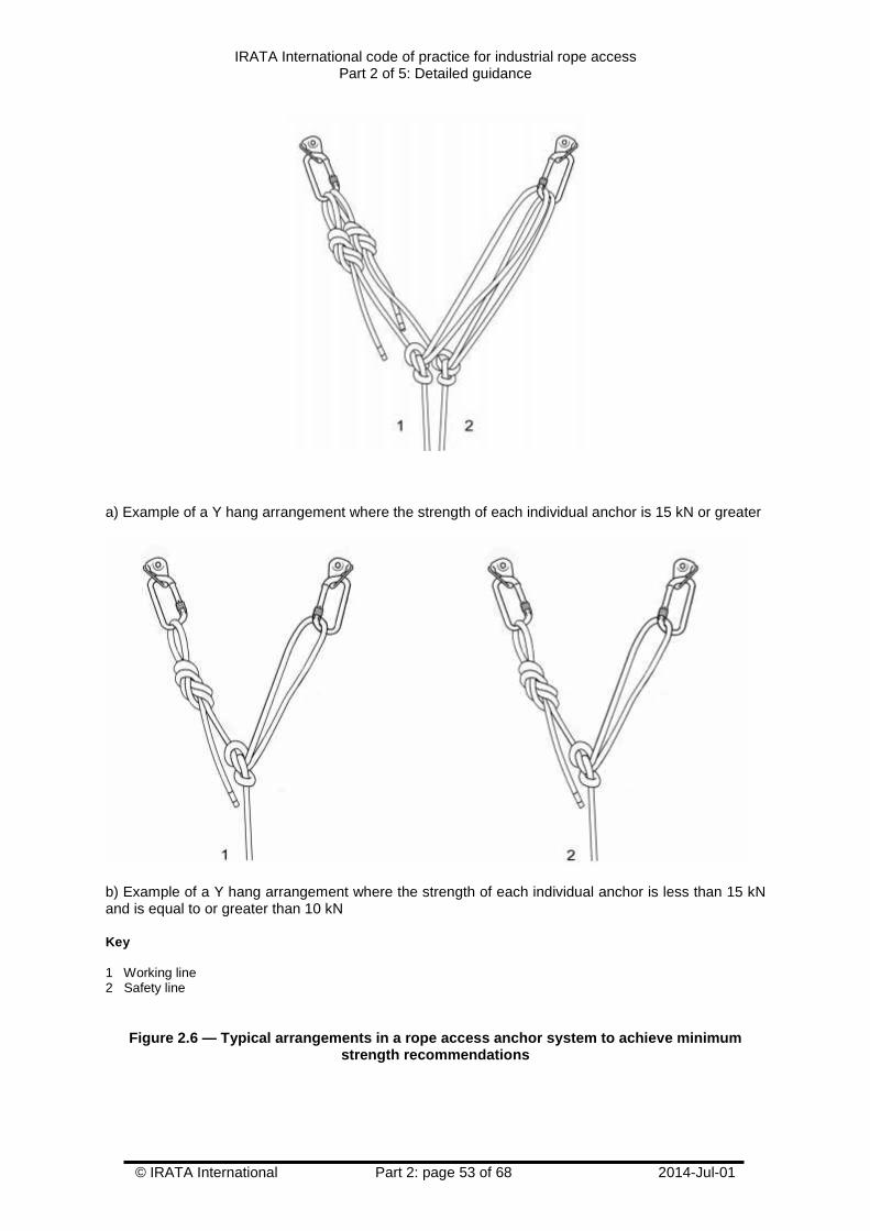
IRATA International code of practice for industrial rope accessPart 2 of 5: Detailed guidance
© IRATA International Part 2: page 53 of 68 2014-Jul-01
a) Example of a Y hang arrangement where the strength of each individual anchor is 15 kN or greater
b) Example of a Y hang arrangement where the strength of each individual anchor is less than 15 kNand is equal to or greater than 10 kN
Key
1 Working line2 Safety line
Figure 2.6 — Typical arrangements in a rope access anchor system to achieve minimumstrength recommendations
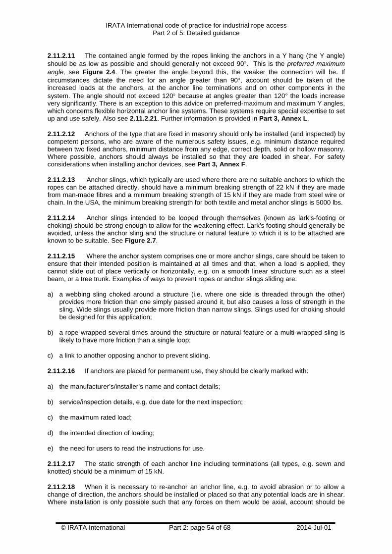
IRATA International code of practice for industrial rope accessPart 2 of 5: Detailed guidance
© IRATA International Part 2: page 54 of 68 2014-Jul-01
2.11.2.11 The contained angle formed by the ropes linking the anchors in a Y hang (the Y angle)should be as low as possible and should generally not exceed 90. This is the preferred maximumangle, see Figure 2.4. The greater the angle beyond this, the weaker the connection will be. Ifcircumstances dictate the need for an angle greater than 90, account should be taken of theincreased loads at the anchors, at the anchor line terminations and on other components in thesystem. The angle should not exceed 120 because at angles greater than 120° the loads increasevery significantly. There is an exception to this advice on preferred-maximum and maximum Y angles,which concerns flexible horizontal anchor line systems. These systems require special expertise to setup and use safely. Also see 2.11.2.21. Further information is provided in Part 3, Annex L.
2.11.2.12 Anchors of the type that are fixed in masonry should only be installed (and inspected) bycompetent persons, who are aware of the numerous safety issues, e.g. minimum distance requiredbetween two fixed anchors, minimum distance from any edge, correct depth, solid or hollow masonry.Where possible, anchors should always be installed so that they are loaded in shear. For safetyconsiderations when installing anchor devices, see Part 3, Annex F.
2.11.2.13 Anchor slings, which typically are used where there are no suitable anchors to which theropes can be attached directly, should have a minimum breaking strength of 22 kN if they are madefrom man-made fibres and a minimum breaking strength of 15 kN if they are made from steel wire orchain. In the USA, the minimum breaking strength for both textile and metal anchor slings is 5000 lbs.
2.11.2.14 Anchor slings intended to be looped through themselves (known as lark’s-footing orchoking) should be strong enough to allow for the weakening effect. Lark's footing should generally beavoided, unless the anchor sling and the structure or natural feature to which it is to be attached areknown to be suitable. See Figure 2.7.
2.11.2.15 Where the anchor system comprises one or more anchor slings, care should be taken toensure that their intended position is maintained at all times and that, when a load is applied, theycannot slide out of place vertically or horizontally, e.g. on a smooth linear structure such as a steelbeam, or a tree trunk. Examples of ways to prevent ropes or anchor slings sliding are:
a) a webbing sling choked around a structure (i.e. where one side is threaded through the other)provides more friction than one simply passed around it, but also causes a loss of strength in thesling. Wide slings usually provide more friction than narrow slings. Slings used for choking shouldbe designed for this application;
b) a rope wrapped several times around the structure or natural feature or a multi-wrapped sling islikely to have more friction than a single loop;
c) a link to another opposing anchor to prevent sliding.
2.11.2.16 If anchors are placed for permanent use, they should be clearly marked with:
a) the manufacturer’s/installer’s name and contact details;
b) service/inspection details, e.g. due date for the next inspection;
c) the maximum rated load;
d) the intended direction of loading;
e) the need for users to read the instructions for use.
2.11.2.17 The static strength of each anchor line including terminations (all types, e.g. sewn andknotted) should be a minimum of 15 kN.
2.11.2.18 When it is necessary to re-anchor an anchor line, e.g. to avoid abrasion or to allow achange of direction, the anchors should be installed or placed so that any potential loads are in shear.Where installation is only possible such that any forces on them would be axial, account should be
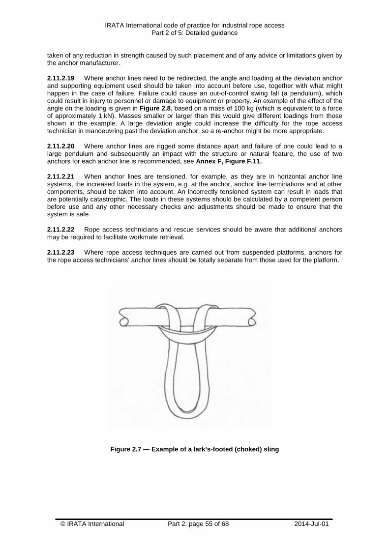
IRATA International code of practice for industrial rope accessPart 2 of 5: Detailed guidance
© IRATA International Part 2: page 55 of 68 2014-Jul-01
taken of any reduction in strength caused by such placement and of any advice or limitations given bythe anchor manufacturer.
2.11.2.19 Where anchor lines need to be redirected, the angle and loading at the deviation anchorand supporting equipment used should be taken into account before use, together with what mighthappen in the case of failure. Failure could cause an out-of-control swing fall (a pendulum), whichcould result in injury to personnel or damage to equipment or property. An example of the effect of theangle on the loading is given in Figure 2.8, based on a mass of 100 kg (which is equivalent to a forceof approximately 1 kN). Masses smaller or larger than this would give different loadings from thoseshown in the example. A large deviation angle could increase the difficulty for the rope accesstechnician in manoeuvring past the deviation anchor, so a re-anchor might be more appropriate.
2.11.2.20 Where anchor lines are rigged some distance apart and failure of one could lead to alarge pendulum and subsequently an impact with the structure or natural feature, the use of twoanchors for each anchor line is recommended, see Annex F, Figure F.11.
2.11.2.21 When anchor lines are tensioned, for example, as they are in horizontal anchor linesystems, the increased loads in the system, e.g. at the anchor, anchor line terminations and at othercomponents, should be taken into account. An incorrectly tensioned system can result in loads thatare potentially catastrophic. The loads in these systems should be calculated by a competent personbefore use and any other necessary checks and adjustments should be made to ensure that thesystem is safe.
2.11.2.22 Rope access technicians and rescue services should be aware that additional anchorsmay be required to facilitate workmate retrieval.
2.11.2.23 Where rope access techniques are carried out from suspended platforms, anchors forthe rope access technicians’ anchor lines should be totally separate from those used for the platform.
Figure 2.7 — Example of a lark’s-footed (choked) sling
IRATA International code of practice for industrial rope accessPart 2 of 5: Detailed guidance
© IRATA International Part 2: page 56 of 68 2014-Jul-01
Key
1 Anchor line2 Position of deviation anchor
Figure 2.8 — Example of how the angle at a deviation anchor affects its loading
2.11.3 Use of anchor lines
2.11.3.1 Rigging and de-rigging
2.11.3.1.1 Anchor lines should be rigged to avoid any surface that could damage them (see 2.7.10).
2.11.3.1.2 Rope access technicians should not ascend or descend any anchor lines withoutconfirmation from the rope access safety supervisor that it is safe to do so, following pre-descent/pre-ascent checks.
2.11.3.1.3 Rope access technicians should normally descend vertically with the minimum amountof swing (pendulum) to minimize the risk of abrasion to the anchor line or putting unnecessary stresson it or the anchors.
2.11.3.1.4 On long descents, anchors providing lateral restraint (e.g. deviation anchors) could befitted on the anchor lines to enable the rope access technicians to maintain their position withoutbeing buffeted too much by the wind.
2.11.3.1.5 Deviation anchors are also used to avoid hazards, e.g. sharp edges; hot surfaces. Theyshould be robust enough not to fail at any potential load to which they could be subjected (see Figure2.8).
2.11.3.1.6 The effects of wind on the free end of anchor lines should be taken into account. Careshould be taken to ensure that the tail end of anchor lines cannot snag on dangerous objects, such as
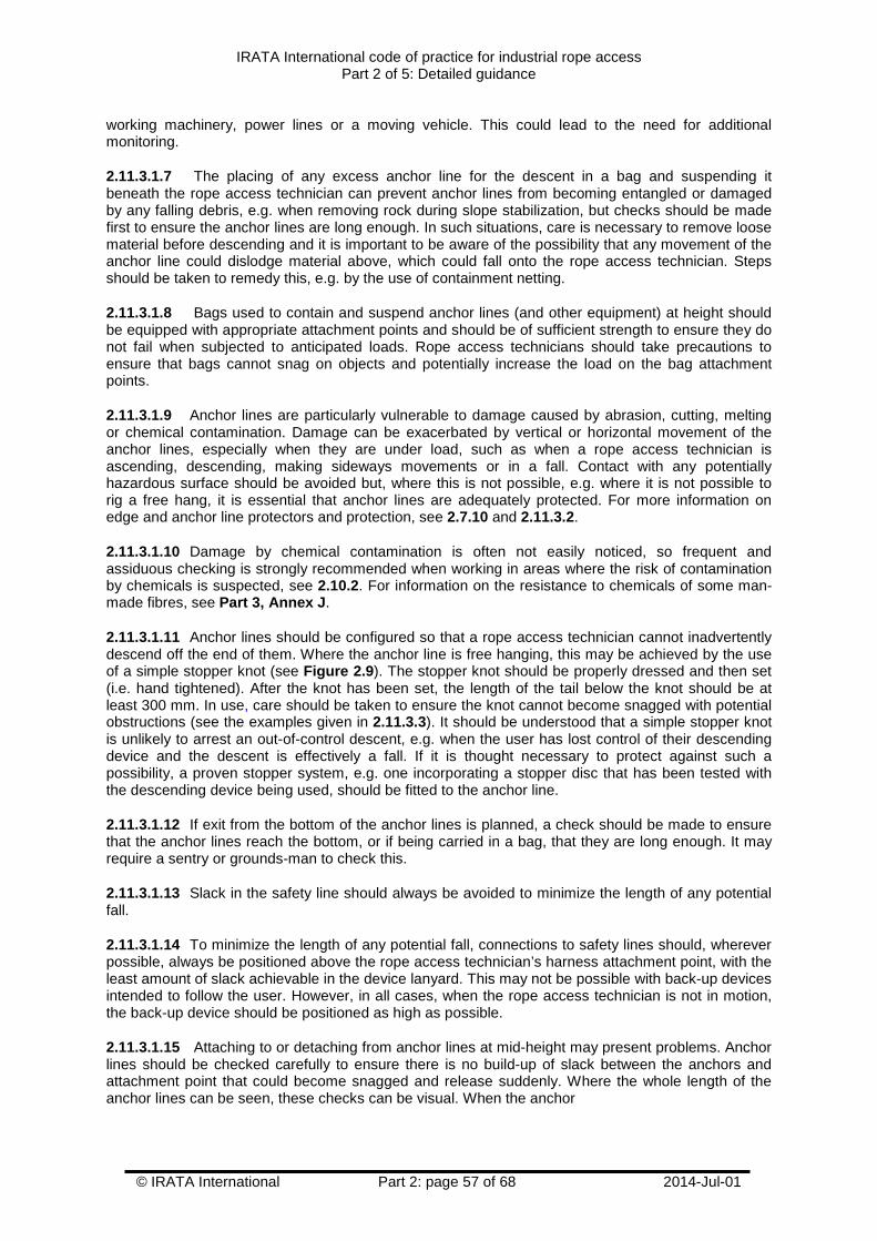
IRATA International code of practice for industrial rope accessPart 2 of 5: Detailed guidance
© IRATA International Part 2: page 57 of 68 2014-Jul-01
working machinery, power lines or a moving vehicle. This could lead to the need for additionalmonitoring.
2.11.3.1.7 The placing of any excess anchor line for the descent in a bag and suspending itbeneath the rope access technician can prevent anchor lines from becoming entangled or damagedby any falling debris, e.g. when removing rock during slope stabilization, but checks should be madefirst to ensure the anchor lines are long enough. In such situations, care is necessary to remove loosematerial before descending and it is important to be aware of the possibility that any movement of theanchor line could dislodge material above, which could fall onto the rope access technician. Stepsshould be taken to remedy this, e.g. by the use of containment netting.
2.11.3.1.8 Bags used to contain and suspend anchor lines (and other equipment) at height shouldbe equipped with appropriate attachment points and should be of sufficient strength to ensure they donot fail when subjected to anticipated loads. Rope access technicians should take precautions toensure that bags cannot snag on objects and potentially increase the load on the bag attachmentpoints.
2.11.3.1.9 Anchor lines are particularly vulnerable to damage caused by abrasion, cutting, meltingor chemical contamination. Damage can be exacerbated by vertical or horizontal movement of theanchor lines, especially when they are under load, such as when a rope access technician isascending, descending, making sideways movements or in a fall. Contact with any potentiallyhazardous surface should be avoided but, where this is not possible, e.g. where it is not possible torig a free hang, it is essential that anchor lines are adequately protected. For more information onedge and anchor line protectors and protection, see 2.7.10 and 2.11.3.2.
2.11.3.1.10 Damage by chemical contamination is often not easily noticed, so frequent andassiduous checking is strongly recommended when working in areas where the risk of contaminationby chemicals is suspected, see 2.10.2. For information on the resistance to chemicals of some man-made fibres, see Part 3, Annex J.
2.11.3.1.11 Anchor lines should be configured so that a rope access technician cannot inadvertentlydescend off the end of them. Where the anchor line is free hanging, this may be achieved by the useof a simple stopper knot (see Figure 2.9). The stopper knot should be properly dressed and then set(i.e. hand tightened). After the knot has been set, the length of the tail below the knot should be atleast 300 mm. In use, care should be taken to ensure the knot cannot become snagged with potentialobstructions (see the examples given in 2.11.3.3). It should be understood that a simple stopper knotis unlikely to arrest an out-of-control descent, e.g. when the user has lost control of their descendingdevice and the descent is effectively a fall. If it is thought necessary to protect against such apossibility, a proven stopper system, e.g. one incorporating a stopper disc that has been tested withthe descending device being used, should be fitted to the anchor line.
2.11.3.1.12 If exit from the bottom of the anchor lines is planned, a check should be made to ensurethat the anchor lines reach the bottom, or if being carried in a bag, that they are long enough. It mayrequire a sentry or grounds-man to check this.
2.11.3.1.13 Slack in the safety line should always be avoided to minimize the length of any potentialfall.
2.11.3.1.14 To minimize the length of any potential fall, connections to safety lines should, whereverpossible, always be positioned above the rope access technician’s harness attachment point, with theleast amount of slack achievable in the device lanyard. This may not be possible with back-up devicesintended to follow the user. However, in all cases, when the rope access technician is not in motion,the back-up device should be positioned as high as possible.
2.11.3.1.15 Attaching to or detaching from anchor lines at mid-height may present problems. Anchorlines should be checked carefully to ensure there is no build-up of slack between the anchors andattachment point that could become snagged and release suddenly. Where the whole length of theanchor lines can be seen, these checks can be visual. When the anchor
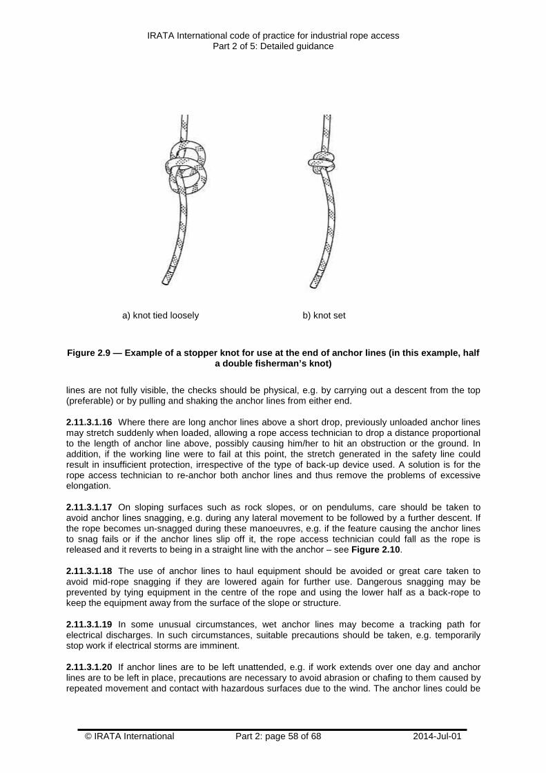
IRATA International code of practice for industrial rope accessPart 2 of 5: Detailed guidance
© IRATA International Part 2: page 58 of 68 2014-Jul-01
a) knot tied loosely b) knot set
Figure 2.9 — Example of a stopper knot for use at the end of anchor lines (in this example, halfa double fisherman’s knot)
lines are not fully visible, the checks should be physical, e.g. by carrying out a descent from the top(preferable) or by pulling and shaking the anchor lines from either end.
2.11.3.1.16 Where there are long anchor lines above a short drop, previously unloaded anchor linesmay stretch suddenly when loaded, allowing a rope access technician to drop a distance proportionalto the length of anchor line above, possibly causing him/her to hit an obstruction or the ground. Inaddition, if the working line were to fail at this point, the stretch generated in the safety line couldresult in insufficient protection, irrespective of the type of back-up device used. A solution is for therope access technician to re-anchor both anchor lines and thus remove the problems of excessiveelongation.
2.11.3.1.17 On sloping surfaces such as rock slopes, or on pendulums, care should be taken toavoid anchor lines snagging, e.g. during any lateral movement to be followed by a further descent. Ifthe rope becomes un-snagged during these manoeuvres, e.g. if the feature causing the anchor linesto snag fails or if the anchor lines slip off it, the rope access technician could fall as the rope isreleased and it reverts to being in a straight line with the anchor – see Figure 2.10.
2.11.3.1.18 The use of anchor lines to haul equipment should be avoided or great care taken toavoid mid-rope snagging if they are lowered again for further use. Dangerous snagging may beprevented by tying equipment in the centre of the rope and using the lower half as a back-rope tokeep the equipment away from the surface of the slope or structure.
2.11.3.1.19 In some unusual circumstances, wet anchor lines may become a tracking path forelectrical discharges. In such circumstances, suitable precautions should be taken, e.g. temporarilystop work if electrical storms are imminent.
2.11.3.1.20 If anchor lines are to be left unattended, e.g. if work extends over one day and anchorlines are to be left in place, precautions are necessary to avoid abrasion or chafing to them caused byrepeated movement and contact with hazardous surfaces due to the wind. The anchor lines could be
IRATA International code of practice for industrial rope accessPart 2 of 5: Detailed guidance
© IRATA International Part 2: page 59 of 68 2014-Jul-01
pulled up and bagged while still being left anchored, or could be sufficiently tensioned to preventabrasion.
2.11.3.1.21 Before any anchor lines are de-rigged, it is essential that all members of the teamconfirm that they are safe and aware that de-rigging is about to take place.
2.11.3.2 Protection methods for anchor lines
2.11.3.2.1 It is essential that precautions are taken to prevent damage to anchor lines, when theyare in use. See 2.7.10 for advice on the selection of protectors for anchor lines and Annex P forrecommended actions for the protection of anchor lines.
2.11.3.2.2 The potential for movement of the anchor lines in both the vertical and horizontal planeswhile in use should be taken into account when assessing the surface to be protected against, thechoice of protection to be used and where the protection is to be positioned.
2.11.3.2.3 Wherever feasible, any hazard that could cause damage to the anchor lines should beremoved. If this is not possible, anchor lines should be rigged so that they hang free for their entirelength and for the duration of the rope access task, and do not contact or have the potential to contactedges, or abrasive or hot surfaces.
2.11.3.2.4 Where anchor lines cannot be rigged to hang free directly from their anchors, they shouldbe suitably protected. One way of achieving this is by the use of a specific engineered solution, suchas a scaffolding barrier made from smooth undamaged tubing over which the anchor lines can runand which is positioned to keep the anchor lines well away from the hazard(s). Other options are theuse of edge protectors and anchor line protectors. A combination of more than one type of protectormay sometimes be necessary to provide adequate protection.
2.11.3.2.5 Edge protectors, e.g. commercially-made rollers; metal edge plates; other cut-resistant orheat-resistant edge protectors, with large radius surfaces offer the best protection at any edge in adrop. These devices should be equipped with a means of maintaining their intended position. Suitablyarranged scaffold tubing, heavy-duty carpet (with a high natural fibre content, such as wool) or thickcanvas padding can also offer good protection and are commonly used.
2.11.3.2.6 Anchor line protectors, which typically comprise a sheath made of a suitable materialwhich encapsulates the anchor line, may be used to protect the anchor lines against contact withabrasive or hot surfaces (but not edges).
2.11.3.2.7 Great care should be taken when choosing an anchor line protector that it is going tooffer sufficient protection against the surface with which it may be in contact. It should be able towithstand use in the chosen location without wearing through or melting and exposing an anchor lineto the abrasive or hot surface. Anchor line protectors used to protect against hot surfaces should be ofa type intended for this purpose.
2.11.3.2.8 It should be noted that some anchor line protectors can obscure the anchor lines fromview and thus make it difficult or impossible to see whether or not damage is being caused to them,e.g. because the anchor line protector has been worn through.
2.11.3.2.9 Anchor line protectors made from a single or even double thickness of material might notoffer sufficient protection against sharp edges and are not recommended for such use unless themanufacturer specifically states in the user information that they are.
2.11.3.2.10 The use of anchor line protectors made from polyvinyl chloride (PVC) coated textilesshould be avoided where the design is such that this material is in direct contact with the anchor line,due to potential heat caused by friction, which can cause melting of the PVC.
2.11.3.2.11 If anchor line protectors are to be used to protect against surfaces that are significantlyabrasive or if they are to be used to protect against hot surfaces, it is recommended that each anchorline is protected by its own anchor line protector, unless the manufacturer states otherwise or unless
IRATA International code of practice for industrial rope accessPart 2 of 5: Detailed guidance
© IRATA International Part 2: page 60 of 68 2014-Jul-01
there is another good reason not to do so. In the event of the failure (e.g. wearing through) of a singleanchor line protector which is being used for both anchor lines, damage is likely to be caused to bothanchor lines at the same time, with the potential for a catastrophic failure of both if an incident were tooccur, e.g. a fall.
2.11.3.2.12 Where one anchor line protector is used for both anchor lines, and is to be tethered to ananchor line rather than to the structure, it is normally attached to the safety line only, as the safety lineis less likely to stretch than the working line, thus minimising the chance of accidental abrasion.
2.11.3.2.13 Sometimes, it may be appropriate to rig the safety line in a position away from theworking line, e.g. to avoid any potential hazardous area and the possibility of both the working lineand the safety line failing simultaneously. If the working line and the safety line are some distanceapart, an anchor line protector should be used for each anchor line.
2.11.3.2.14 In mid-anchor line situations, attachment of an anchor line protector to the structure ornatural feature rather than to the anchor line is preferable, as anchor line elongation could result inpoor protection or no protection at all if the anchor line protector is fastened to the anchor line. If exitis to be from the bottom of the anchor lines but retrieval of the anchor lines is to be from the top, theanchor line protector should be fastened to the anchor line.
2.11.3.2.15 It is essential that edge protectors and anchor line protectors maintain their intendedposition. Care is necessary to ensure the edge protector or anchor line protector remains in thecorrect place when the anchor line is loaded, or that it is repositioned correctly when more than oneperson uses the anchor line. This may be particularly relevant if users are of different weights(masses). The consequences of a failure of the working line and the subsequent elongation of thesafety line should be taken into account, which may prompt the use of several edge protectors oranchor line protectors.
2.11.3.2.16 Edge protectors and anchor line protectors of a type that can be located on the anchorlines anywhere along them (e.g. without having to thread the end of an anchor line through the edgeprotector or anchor line protector) are generally recommended. Anchor line protectors that have atouch-and-close system of fastening are useful when attaching to an anchor line part way down adrop. They are usually provided with a thin cord so that they can be fixed to the structure, naturalfeature or anchor line. One design of anchor line protector simply grips the anchor line by friction tokeep it in place.
2.11.4 Additional safety measures
Rope access systems should be configured and used in such a way to prevent falls. Nevertheless,consideration should be given to the unlikely event of a fall, e.g. in the case of incorrect use or failureof a piece of equipment. Some of the points below are made in other sections of this code of practicebut are repeated here for reinforcement. Rope access systems should be configured to ensure:
a) any potential fall distance is minimized, e.g. slack in the anchor lines is avoided or minimized (forinformation on fall factors, fall distances and associated risks, see Part 3, Annex Q);
b) adequate clearance distance is provided, so that the rope access technician is prevented fromimpacting with the ground or obstacle in the path of a fall (e.g. allow for the extension of anenergy absorber during deployment or elongation of the safety line);
c) any swing fall (pendulum) is kept to an acceptable minimum;
d) the maximum impact load a rope access technician could experience is as low as possible andnever any greater than 6 kN;
e) adequate protection is provided for anchor lines and other equipment in the system to preventthem from failure during use and during a fall, its arrest or post-fall suspension;
f) following an incident, rope access technicians are likely to be in a position to rescue themselves;
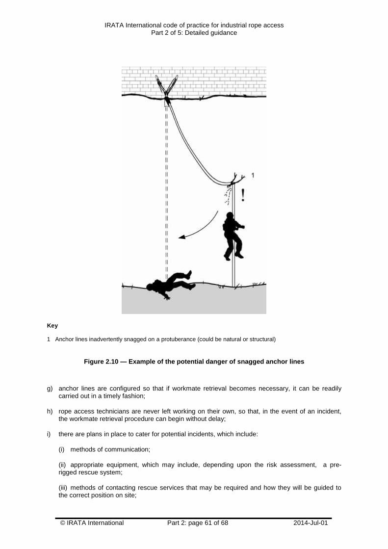
IRATA International code of practice for industrial rope accessPart 2 of 5: Detailed guidance
© IRATA International Part 2: page 61 of 68 2014-Jul-01
Key
1 Anchor lines inadvertently snagged on a protuberance (could be natural or structural)
Figure 2.10 — Example of the potential danger of snagged anchor lines
g) anchor lines are configured so that if workmate retrieval becomes necessary, it can be readilycarried out in a timely fashion;
h) rope access technicians are never left working on their own, so that, in the event of an incident,the workmate retrieval procedure can begin without delay;
i) there are plans in place to cater for potential incidents, which include:
(i) methods of communication;
(ii) appropriate equipment, which may include, depending upon the risk assessment, a pre-rigged rescue system;
(iii) methods of contacting rescue services that may be required and how they will be guided tothe correct position on site;
IRATA International code of practice for industrial rope accessPart 2 of 5: Detailed guidance
© IRATA International Part 2: page 62 of 68 2014-Jul-01
(iv) for all team members, the means to travel up and down the anchor lines and to be able tocarry out a rapid workmate retrieval.
2.11.5 The use of knots
2.11.5.1 Knots are used typically to form terminations in textile anchor lines and there are manythat are suitable for use in rope access. Although knots reduce the overall strength of a rope (whichshould be taken into consideration when choosing a rope), one benefit is that they absorb energy.Some knots absorb more energy than others. An example of a knot that is particularly good atabsorbing energy is the scaffold knot, which is often used to terminate an anchor lanyard.
2.11.5.2 It is essential that rope access technicians should be able to tie, dress and setappropriately a range of the most commonly used knots and to be confident that they will be able totie them when in difficult circumstances. In the workplace, knots should only be tied by persons with athorough knowledge of knots and knot-tying techniques.
2.11.5.3 When choosing a suitable knot, rope access technicians should take into account thefollowing:
a) their own skill in tying that particular knot;
b) the suitability of the knot for the task and the anticipated way in which it may be loaded, includingthe potential forces envisaged;
c) the reduction of strength in the anchor line, device lanyard or anchor lanyard that the knotcreates;
d) the ease with which the knot may be tied and untied;
e) where required, the ability of the knot to pass through or over potential obstructions, e.g. pulleys.
2.11.5.4 The tails of all knots should be at least 100 mm long, once the knot has been set. Knotsshould never be tied in anchor lines made from wire rope.
2.11.5.5 The reduction in the strength of the rope caused by the knot varies, dependent upon thetype of knot and the accuracy and neatness with which it is tied. Neatening a knot, e.g. making surethe ropes in the knot are parallel and tightened equally, is known as dressing. Typical strength losses,showing the lower and upper values between a well-dressed knot and a poorly-dressed knot, are:
a) scaffold knot: 23 % to 33 %;
b) figure-of-eight on a bight: 23 % to 34 %;
c) figure-of-nine on a bight: 16 % to 32 %;
d) figure-of-ten on a bight: 13 % to 27 %;
e) overhand on the bight: 32 % to 42 %:
f) double figure-of-eight on the bight (bunny knot): 23 % to 39 %;
g) alpine butterfly: 28 % to 39 %;
h) bowline: 26 % to 45 %.
IRATA International code of practice for industrial rope accessPart 2 of 5: Detailed guidance
© IRATA International Part 2: page 63 of 68 2014-Jul-01
2.11.6 Work teams
2.11.6.1 A work team comprises a rope access team, i.e. the rope access techniciansparticipating in the rope access work, and any supporting personnel. Because of the locations and thespecialized nature of the work, all work teams should be properly supervised and be self-supportive,e.g. with respect to rescue.
2.11.6.2 IRATA International requires that a rope access team consists of at least two ropeaccess technicians. However, there are many situations that require more than a two-person ropeaccess team, depending, for example, on the nature of the work; site conditions; competency of thework team; potential rescue scenarios.
2.11.6.3 A rope access team size of two should only be considered in circumstances whereretrieval and rescue by either rope access technician of his/her workmate could be achieved rapidlyand unaided by third parties, e.g. where any potential rescue would be a direct lower of the casualtyto a safe place. Wherever a potential rescue of the casualty could be other than such a direct lower, ateam of three rope access technicians should be regarded as the normal minimum team size, unlessother specific arrangements are in place that have been tried and tested by the rope accesstechnicians.
2.11.6.4 One member of the work team has to be qualified as an IRATA International Level 3 ropeaccess technician and be competent to supervise rope access safety (the rope access safetysupervisor – see 2.5.2 and 2.6).
2.11.6.5 Adequate supervision should be provided for each worksite. It may be appropriate toemploy more than one Level 3 rope access safety supervisor, depending on the circumstances.Examples are:
a) the number of rope access technicians working on the site;
b) complex work situations;
c) arduous environmental conditions;
d) when operating on a work site with more than one discrete working area.
2.11.6.6 Both the Level 3 rope access safety supervisor and their company should ensure beforework commences that the rescue procedures are adequate for that situation and that all members ofthe team have been suitably briefed. Sufficient personnel and resources should be readily available tocarry out those procedures, in case the need arises.
2.11.6.7 Where the work takes place in a particularly hazardous or restricted area, e.g. one whichcould give rise to poisoning or asphyxiation, the training, abilities, experience, competence and size ofthe work team should be of a level that is suitable to deal with any emergency arising out ofundertaking the work.
2.11.6.8 Where work is carried out over water, suitable rescue equipment should be provided andmeasures adopted to arrange for prompt rescue of anyone in danger of drowning.
2.11.7 Pre-work checking
2.11.7.1 If a permit to work is required, this should already have been obtained and checked.Permits to work are an effective method of isolating a hazard before work starts and to ensure that itremains isolated while work is in progress and until everyone is clear of the danger area.
2.11.7.2 At the start of each day, and as determined by changing site conditions, the work teamshould review the risks that could affect the safe, efficient and effective outcome of the job. This pre-work briefing should refer to the safety method statement, the risk assessment and the rescue planalready prepared, as well as the rôle of each member of the team.
IRATA International code of practice for industrial rope accessPart 2 of 5: Detailed guidance
© IRATA International Part 2: page 64 of 68 2014-Jul-01
2.11.7.3 Any special precautions required should be put into effect (e.g. standby boat alerted;radio check; gas checks; noxious chemicals check; work on or near hot surfaces).
2.11.7.4 Rope access technicians should carefully examine their own equipment, e.g. harnesses;anchor line devices; device lanyards; connectors, before starting work, to ensure it is in goodcondition. This is known as pre-use checking. The rope access safety supervisor should ensure thisoccurs. This checking should continue during the course of the job. In addition, there should be afurther check by another member of the team, known as buddy checking, to ensure, for example, thateach other’s harness buckles are correctly fastened and adjusted, that device lanyards and anchorlanyards are attached correctly and that connectors are fastened correctly. Buddy checking by teammembers is good practice and should be continued throughout the day, including:
a) after the rope access technician has put on his/her harness and assembled his/her equipment;
b) when the rope access technician has attached to the anchor lines;
c) at all times when the rope access technician is engaged in rope access manoeuvres.
2.11.7.5 At the beginning of each working day and at other times as appropriate, e.g. when theanchor lines are relocated during the day, the rope access safety supervisor should carry out a pre-use check to ensure that all the anchors and anchor lines (wire and textile), and the structure ornatural feature to which they are attached, are satisfactory. This pre-use check should include anypoints on the anchor lines where abrasion or other damage, e.g. caused by hot surfaces, could occur.The rope access safety supervisor should also take responsibility for checking anchor lines for lengthand that, where appropriate, termination stopper knots are in place and secure.
2.11.7.6 Sometimes, an announcement has to be made to warn other workers that the work iscommencing. This is common practice offshore and is often a requirement of the permit to work.
2.11.8 Exclusion zones
2.11.8.1 General
2.11.8.1.1 Exclusion zones may need to be set up to protect people from falling or to protect peopleagainst falling objects from above the area of rope access operations, or anyone below. They mayalso be required for reasons other than fall protection, e.g. to protect against exposure to: radiation;radio waves such as those emitted by mobile phone antennae; areas of high temperature; chemicalpollution. Exclusion zones may be necessary at several levels, e.g. above anchor level; at anchorlevel; at intermediate levels; at ground level. See Figure 2.11 for different types of exclusion zones.
2.11.8.1.2 In some circumstances, the work team may require additional support members forsafety reasons, e.g. where there is a need to prevent the public entering an area that could bethreatened by falling objects, or to guard against vandals tampering with suspension equipment. Theadditional persons required to act as sentries need not be trained in rope access work, provided thatthey are not counted as being a member of the rope access team.
2.11.8.2 Protection of third parties
2.11.8.2.1 Where required, precautions appropriate to the situation should be provided to preventequipment or materials falling in such a way that other people might be endangered.
2.11.8.2.2 Methods of providing precautions include securing all tools to either the rope accesstechnician or to separate lines. Normally, items weighing over eight kilograms should be attached to aseparate line, while those below this weight may be secured to the worker (For more information onthe use of tools and other work equipment, see Part 3, Annex M.) In addition, an exclusion zoneshould be established beneath the rope access site. Scaffold fans, temporary roof structures orcontainment nets or sheets could be provided to contain falling materials into safe and confinedareas. These should be strong enough to retain any equipment or debris that might fall.
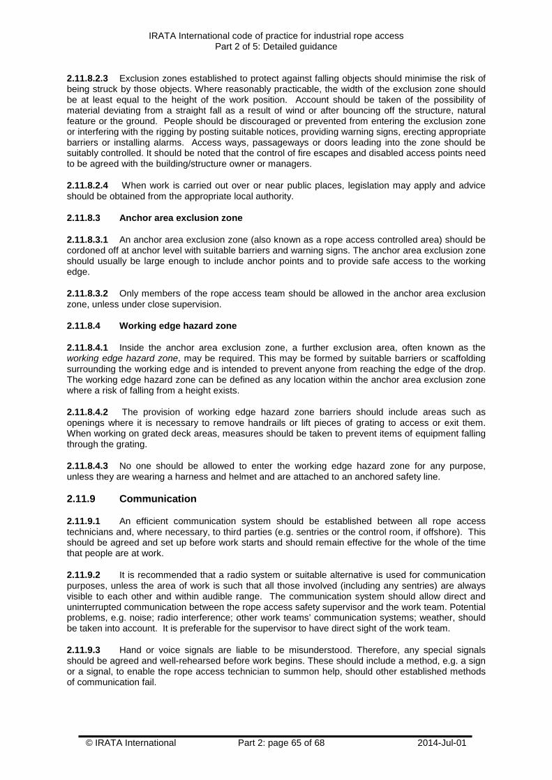
IRATA International code of practice for industrial rope accessPart 2 of 5: Detailed guidance
© IRATA International Part 2: page 65 of 68 2014-Jul-01
2.11.8.2.3 Exclusion zones established to protect against falling objects should minimise the risk ofbeing struck by those objects. Where reasonably practicable, the width of the exclusion zone shouldbe at least equal to the height of the work position. Account should be taken of the possibility ofmaterial deviating from a straight fall as a result of wind or after bouncing off the structure, naturalfeature or the ground. People should be discouraged or prevented from entering the exclusion zoneor interfering with the rigging by posting suitable notices, providing warning signs, erecting appropriatebarriers or installing alarms. Access ways, passageways or doors leading into the zone should besuitably controlled. It should be noted that the control of fire escapes and disabled access points needto be agreed with the building/structure owner or managers.
2.11.8.2.4 When work is carried out over or near public places, legislation may apply and adviceshould be obtained from the appropriate local authority.
2.11.8.3 Anchor area exclusion zone
2.11.8.3.1 An anchor area exclusion zone (also known as a rope access controlled area) should becordoned off at anchor level with suitable barriers and warning signs. The anchor area exclusion zoneshould usually be large enough to include anchor points and to provide safe access to the workingedge.
2.11.8.3.2 Only members of the rope access team should be allowed in the anchor area exclusionzone, unless under close supervision.
2.11.8.4 Working edge hazard zone
2.11.8.4.1 Inside the anchor area exclusion zone, a further exclusion area, often known as theworking edge hazard zone, may be required. This may be formed by suitable barriers or scaffoldingsurrounding the working edge and is intended to prevent anyone from reaching the edge of the drop.The working edge hazard zone can be defined as any location within the anchor area exclusion zonewhere a risk of falling from a height exists.
2.11.8.4.2 The provision of working edge hazard zone barriers should include areas such asopenings where it is necessary to remove handrails or lift pieces of grating to access or exit them.When working on grated deck areas, measures should be taken to prevent items of equipment fallingthrough the grating.
2.11.8.4.3 No one should be allowed to enter the working edge hazard zone for any purpose,unless they are wearing a harness and helmet and are attached to an anchored safety line.
2.11.9 Communication
2.11.9.1 An efficient communication system should be established between all rope accesstechnicians and, where necessary, to third parties (e.g. sentries or the control room, if offshore). Thisshould be agreed and set up before work starts and should remain effective for the whole of the timethat people are at work.
2.11.9.2 It is recommended that a radio system or suitable alternative is used for communicationpurposes, unless the area of work is such that all those involved (including any sentries) are alwaysvisible to each other and within audible range. The communication system should allow direct anduninterrupted communication between the rope access safety supervisor and the work team. Potentialproblems, e.g. noise; radio interference; other work teams’ communication systems; weather, shouldbe taken into account. It is preferable for the supervisor to have direct sight of the work team.
2.11.9.3 Hand or voice signals are liable to be misunderstood. Therefore, any special signalsshould be agreed and well-rehearsed before work begins. These should include a method, e.g. a signor a signal, to enable the rope access technician to summon help, should other established methodsof communication fail.
IRATA International code of practice for industrial rope accessPart 2 of 5: Detailed guidance
© IRATA International Part 2: page 66 of 68 2014-Jul-01
Figure 2.11 — Examples of different types of exclusion zone
2.11.10 Welfare
2.11.10.1 Rope access technicians require adequate facilities where they can rest in the dry,protected from the cold or heat, and where they can obtain fresh water, store any additional clothingand be able to wash. They should also be provided with, or have access to, adequate toilet facilities.
2.11.10.2 In calculating the length of shifts and rest periods for rope access technicians,consideration should be given to the effects of adverse climatic conditions and/or difficult or veryexposed worksites, because these can affect efficiency and tiredness levels. Working in high andexposed places is likely to subject the rope access technician to factors such as wind chill or buffetingby the wind, which can have a significant effect on output at even quite moderate wind speeds. Formore information on the effect of wind and height on working times, see Part 3, Annex O. Similarly,work in high temperatures can result in heat exhaustion or fainting. Carrying adequate drinking waterin these circumstances is essential. Working short shifts minimizes risk to workers in suchenvironments.
Key
1 Anchor area exclusion zone2 Working edge hazard zone3 Exclusion zone at intermediate level4 Exclusion zone at bottom level
IRATA International code of practice for industrial rope accessPart 2 of 5: Detailed guidance
© IRATA International Part 2: page 67 of 68 2014-Jul-01
2.11.10.3 The nature of the work equipment to be used should also be taken into account whencalculating the length of shifts and rest periods, to prevent unacceptable discomfort or tiredness of therope access technician, which could affect his/her safety.
2.11.11 Emergency procedures
2.11.11.1 Even though great care and attention may be given to safe working, accidents can stillhappen. The survival of an injured or otherwise immobile person often depends on the speed ofrescue and the care given to the casualty during and after rescue. Consequently, great importanceshould be attached to examining the work site at appropriate times, e.g. each day; each change ofjob; changing environmental conditions, to assess all feasible emergency scenarios and to plan howany resulting rescues would be carried out.
2.11.11.2 Provisions should be made to ensure that help is provided promptly to any rope accesstechnician who needs it. Rope access technicians should be skilled in appropriate rescue techniques,which should form part of their basic and on-going training.
2.11.11.3 Rescue equipment should always be present and ready for immediate deployment at theworksite. This equipment should be sufficient to carry out a rescue from any situation on the site. Thiscould be the rope access technician’s normal rope access equipment, preferably rigged for rescue,e.g. the working line and safety line established with releasable anchors to allow rapid implementationof lowering or hauling in an emergency.
2.11.11.4 Clear instructions should be given to rope access technicians on the procedures to betaken in site emergencies that could occur unexpectedly, e.g. on nuclear sites, offshore platforms,refineries.
2.11.11.5 The rope access team should have a planned method for rescue that includes thefollowing:
a) a clearly defined leader;
b) adequate equipment;
c) competent rope access technicians;
d) practised techniques appropriate to the worksite;
e) an awareness of the higher loads involved in rescue;
f) an awareness of suspension intolerance (also known as suspension trauma, suspension syncopeand harness induced pathology – see Part 3, Annex G), its symptoms and, in particular, how tomanage someone suspected of suffering from the condition during the suspension and post-suspension phases of rescue;
g) the provision of medical aid if required.
2.11.11.6 There should be a first aid kit at each worksite and someone competent in first aid at alltimes.
2.11.12 Reporting of incidents and accidents
2.11.12.1 Reporting accidents and ill health at work is a legal requirement in some countries.Employers should check their own country’s legislation.
2.11.12.2 In addition to any legal requirements, an accurate record of all accidents or near-missesshould be kept, including measures to avoid a reoccurrence. All employees should be encouraged toreport near-misses.
IRATA International code of practice for industrial rope accessPart 2 of 5: Detailed guidance
© IRATA International Part 2: page 68 of 68 2014-Jul-01
2.11.12.3 It is essential that the IRATA International work and safety statistics be completed for allhours worked on rope, accidents, incidents or near misses and returned promptly to IRATAInternational when requested. The statistics gathered from this information are used in the IRATAInternational Work and Safety Analysis to highlight the industry’s safety record, in order to support theuse of rope access methods. To assist with IRATA International’s aim of continuous improvement ofworking methods, work and safety statistics are studied for trends so that any lessons may belearned.
2.11.13 End of shifts
At the end of each shift, equipment such as anchor lines, tools and components should be secured orstored safely (see 2.10.7). While carrying out this procedure, care should be taken to avoid droppingequipment, which could cause injury. Personal equipment should only be removed when the ropeaccess technician is in a safe place. A formal hand-over to the next shift should take place inaccordance with local procedures and rules, at which time any relevant information should be passedon.
2.11.14 Termination of a job
At the termination of a job, care should be taken to clear the site properly, with a final inspection of thearea before any permit to work is handed back.
2.11.15 Expanded techniques
Rope access is primarily concerned with movement up or down suspended ropes and working fromthem, and is considered to be primarily a technique for work positioning. However, the techniques andequipment used for this purpose are sometimes expanded to encompass traversing, aid climbing,lead climbing and other forms of access. The resulting system can range from a work positioningsystem to a fall arrest system, with hybrid systems somewhere in between. For more information, seePart 3, Annex L. In addition, non-harness-based height access methods and fall protection, e.g.scaffolding; nets, may sometimes be incorporated in the work plan.