Embed Size (px)
DESCRIPTION
STANDARD SPECIFICATIONS ANDCODE OF PRACTICE FOR ROAD BRIDGESSECTION: IILOADS AND STRESSES(Fifth Revision)
Citation preview

IRC:S-2010
STANDARD SPECIFICATIONS AND
CODE OF PRACTICE FOR ROAD BRIDGES
SECTION: II
LOADS AND STRESSES
(Fifth Revision)
Published by
INDIAN ROADS CONGRESS Kama Koti Marg
Sector-6, R.K. Puram New Delhi-110022
NOVEMBER- 2010
Price Rs. 400/(Packing and postage charges extra)

First published Reprinted Reprinted Second Revision Third Revision Reprinted Reprinted Reprinted Reprinted Reprinted Reprinted Reprinted
Reprinted Reprinted Reprinted Reprinted Reprinted Fourth Revision Reprinted Reprinted Reprinted Reprinted Reprinted Fifth Revision
December, 1958 May, 1962 September, 1963 October, 1964 Metric Units: October, 1966 October, 1967 November, 1969 March, 1972 (incorporates Amendment No. 1-Nov. 1971) February, 1974 (incorporates Amendment No. 2-Nov. 1972) August 1974 (incorporates Amendment No. 3-April1974 and No. 4-August 1974) July, 1977 (Incorporates Amendment No. 5-0ctober, 1976) September, 1981 (Incorporates the changes as given in detail in the last two sub-paras of introduction at page 3) November, 1985 September, 1990 January, 1994 January, 1997 March, 1999 December, 2000 April, 2002 (Incorporates amended Fig. 5 at page 23) August, 2004 (Incorporates uptodate Amendments) August, 2005 April, 2006 September, 2009 (Incorporates Amendment No. 6) November, 2010
(All Rights Reserved. No Part of this Publication shall be reproduced, translated or transmitted in any form or by any means without the
permission of the Indian Roads Congress)
Printed at India Offset Press, New Delhi- 64 (500 Copies)
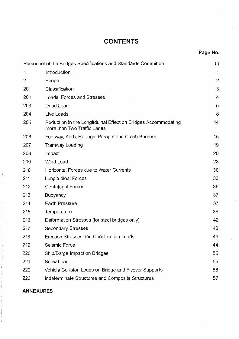
CONTENTS
Personnel of the Bridges Specifications and Standards Committee
1
2
201
202
203
204
205
206
207
208
209
210
211
212
213
214
215
216
217
218
219
220
221
222
223
Introduction
Scope
Classification
Loads, Forces and Stresses
Dead Load
Live Loads
Reduction in the Longitduinal Effect on Bridges Accommodating more than Two Traffic Lanes
Footway, Kerb, Railings, Parapet and Crash Barriers
Tramway Loading
Impact
Wind Load
Horizontal Forces due to Water Currents
Longitudinal Forces
Centrifugal Forces
Buoyancy
Earth Pressure
Temperature
Deformation Stresses (for steel bridges only)
Secondary Stresses
Erection Stresses and Construction Loads
Seismic Force
Ship/Barge Impact on Bridges
Snow Load
Vehicle Collision Loads on Bridge and Flyover Supports
Indeterminate Structures and Composite Structures
ANNEXURES
Page No.
(i)
1
2
3
4
5
8
14
15
19
20
23
30
33
36
37
37
38
42
43
43
44
55
55
56
57


1.
2.
3.
4.
5.
6.
7.
8.
9.
10.
11.
12.
13.
14.
15.
16.
17.
18.
19.
20.
21.
22.
IRC:6-2010
PERSONNEL OF THE BRIDGES SPECIFICATIONS AND STANDARDS COMMITTEE
Singh, Nirma\ Jit (Convenor)
Sinha, A.V. (Co-Convenor)
Sharma, Arun Kumar (Member-Secretary)
Agrawal, K.N.
Alimchandani, C.R.
Banerjee, A.K.
Banerjee, T.B.
Basa, Ashok
Bandyopadhyay, Dr. T.K.
Bongirwar, P.L.
Bhasin, P.C.
Chakraborty, Prof. S.S.
Chakraborti, S.P.
Dhodapkar, A.N.
Gupta, Mahesh
Ghoshal, A.
Joglekar, S.G.
Kand, Dr. C.V.
Koshi, Ninan
Kumar, Prafu\Ja
Kumar, Vijay
Kumar, Dr. Ram
(AS ON 26TH OCTOBER, 2009)
Director General (RD) & Spl. Secretary, Ministry of Road Transport & Highways, New Delhi
Add\. Director General, Ministry of Road Transport & Highways, New Delhi
Chief Engineer (B) S&R, Ministry of Road Transport & Highways, New Delhi
Members
DG(W), CPWD (Retd.), Ghaziabad
Chairman & Managing Director, STUP Consultants Ltd., Mumbai
Member (T), NHAI (Retd.), New Delhi
Chief Engineer (Retd.), Minis'try of Road Transport & Highways, New Delhi
Director (Tech.), B. Engineers & Builders Ltd., Bhubaneswar
Joint Director General (Retd.), Institute for Steel Dev. and Growth, Kolkata
Advisor, L&T, Mumbai
ADG(B) (Retd.) MOST, New Delhi
Managing Director, Consulting Engg. Services (\) Pvt. Ltd., New Delhi
Consultant, Span Consultants (P) Ltd., Naida
Chief Engineer, Ministry of Road Transport & Highways, New Delhi
Executive Director (B&S), RDSO, Lucknow
Director and Vice-President, STUP Consultants Ltd., Kolkata
Director (Engg. Core), STUP Consultants Ltd., Mumbai
Chief Engineer, (Retd.), MP PWD, Bhopal
DG(RD) & AS (Retd.), MOST, Gurgaon
DG(RD) & AS (Retd.), MORT&H, Naida
E-in-C (Retd.), UP PWD, Naida
Chief General Manager, NHAI, New Delhi
( i )

IRC:G-2010
23.
24.
25.
26.
27.
28.
29.
30.
31.
32.
33.
34.
35.
36.
37.
38.
39.
40.
41.
1.
2.
3.
1.
2.
Kumar, Ashok
Manjure, P.Y.
Mukherjee, M.K.
Narain, A.D.
Ninan, R.S.
Puri, S.K.
Patankar, V.L.
Rajagopalan, Dr. N.
Rao, M.V.B.
Roy, Dr. B.C.
Sharma, R.S.
Sharan, G.
Sinha, N.K.
Saha, Dr. G.P.
Tandon, Prof. Mahesh
Velayutham, V.
Vijay, P.B.
Director & Head (Civil Engg.)
Add I. Director General (Dr. V.K. Yadav)
President, IRC
Director Generai(RD) & Spl. Secretary
Secretary General
Merani, N.V.
Bagish, Dr. B.P.
Chief Engineer, Ministry of Road Transport & Highways, New Delhi
Director, Freyssinet Prestressed Concrete Co. Ltd., Mumbai
Chief Engineer (Retd.), MORT&H, New Delhi
DG(RD) & AS (Retd.), MORT&H, Noida
Chief Engineer (Retd.), MORT&H, New Delhi
Member (Technical), National Highways Authority of India, New Delhi
Chief Engineer, Ministry of Road Transport & Highways, New Delhi
Chief Technical Advisor, L& T, Chennai
A-181, Sarita Vihar, New Delhi
Executive Director, Consulting E.ngg. Services (I) Pvt. Ltd., New Delhi
Past Secretary General, IRC, New Delhi
DG(RD) & SS, (Retd.), MORT&H, New Delhi
DG(RD) & SS, (Retd.), MORT&H, New Delhi
Executive Director, Construma Consultancy (P) Ltd., Mumbai
Managing Director, Tandon Consultants (P) Ltd., New Delhi
DG(RD) & SS, (Retd.), MORT&H, New Delhi
DG (W) (Retd.), CPWD, New Delhi
Bureau of Indian Standards, New Delhi
Directorate General Border Roads, New Delhi
Ex-Officio Members
(Deshpande, D.B.) Advisor, Maharashtra Airport Development Authority, Mumbai
(Singh, Nirmal Jit) Ministry of Road Transport & Highways, New Delhi
(lndoria, R.P.) Indian Roads Congress, New Delhi
Corresponding Members
Principal Secretary (Retd.), Maharashtra PWD, Mumbai
C-2/2013, Opp. D.P.S., Vasant Kunj, New Delhi
( ii )

STANDARD SPECIFICATIONS AND CODE OF PRACTICE FOR ROAD BRIDGES
1 INTRODUCTION
IRC:6-2010
The brief history of the Bridge Code given in the Introduction to Section I "General Features of Design" generally applies to Section II also. The draft of Section II for"Loads and Stresses", as discussed at Jaipur Session of the Indian Roads Congress in 1946, was considered further in a number of meetings of the Bridges Committee for finalisation. In the years 1957 and 1958, the work of finalising the draft was pushed on vigorously by the Bridges Committee.
In the Bridges Committee meeting held at Bombay in August 1958, all the comments received till then on the different clauses of this Section were disposed off finally and a drafting Committee consisting of S/Shri S. B. Joshi, K.K. Nambiar, K.F. Anti a and S.K. Ghosh was appointed to work in conjunction with the officers of the Roads Wing of the Ministry for finalising this Section.
This Committee at its meeting held at New Delhi in September 1958 and later through correspondences finalized Section II of the Bridge Code, which was printed in 1958 and reprinted in 1962 and 1963.
The Second Revision of Section II of the IRC:6 Code (1964 edition) included all the amendments, additions and alterations made by the Bridges Specifications and Standards (BSS) Committee in their meetingg held from time to time.
The Executive Committee of the Indian Roads Congress approved the publication of the Third Revision in metric units in 1966.
The Fourth Revision of Section II of the Code (2000 Edition) included all the amendments, additions and alterations made by the BSS Committee in their meetings held from time to time and was reprinted in 2002 with Amendment No.1, reprinted in 2004 with Amendment No. 2 and again reprinted in 2006 with Amendment Nos. 3, 4 and 5.
The current Fifth Revision of Section II of the Code IRC:6 -2010 includes all the amendments, and alterations made by the BSS Committee in their meetings held from time to time.
The Bridges Specifications and Standards Committee and the IRC Council at various meetings approved certain amendments viz. Amendment No. 6 of November 2006 relating to Sub-Clauses 218.2, 222.5, 207.4 and Appendix-2, Amendment No.7 of February 2007 relating to Sub-Clauses of 213.7, Note 4 of Appendix-! and 218.3, Amendment No. 8 of January 2008 relating to Sub-Clauses 214.2(a), 214.5.1.1 and 214.5.2 and new Clause 212 on Wind load.
As approved by the BSS Committee and IRC Council in 2008, the Amendment No. 9 of May 2009 incorporating changes to Clauses 202.3, 208, 209.7 and 218.5 and Combination of Loads for limit state design of bridges has been introduced in Appendix-3, apart from the new Clause 222 on Seismic Force for design of bridges.
1

IRC:6-2010
The Bridges Specifications and Standards Committee in its meeting held on 26'" October, 2009 further approved certain modifications to Clause 210.1, 202.3, 205, Note below Clause 208, 209.1, 209.4, 209.7, 222.5.5, Table 8, Note below Table 8, 222.8, 222.9, Table 1 and deletion of Clause 213.8, 214.5.1.2 and Note below para 8 of Appendix-3. The Convenor of B-2 Committee was authorized to incorporate these modifications in the draft for Fifth Revision of IRC:6, in the light of the comments of some members. The Executive Committee, in its meeting held on 31 51 October, 2009, and the IRC Council in its 189th meeting held on 14'" November, 2009 at Patna approved publishing of the Fifth Revision of IRC:6.
The personnel of the Loads and Stresses Committee (B-2) is given below:
Banerjee, A.K.
Kanhere, O.K.
Parameswaran, (Mrs.) Dr. Lakshmy
Bhowmick, Alok
Dhodapkar, A.N.
Gupta, Vinay
Heggade. V.N.
Huda, Y.S.
Lego, Atop
Jain, Dr. S.K.
Joglekar, S.G.
Kataria, Rajan
Khedkar, S.P.
Members
Verma, G.L.
Convenor
Co-Convenor
Member-Secretary
Mukherjee, M.K.
Mukhopadhyay, Achintya
Pandey, Alok,
Saha, Dr. G.P.
Surana, Dr. C.S.
Sharan, G.
Thandavan, K.B.
Thakkar, Dr. S.K.
Sharma, Aditya
Viswanathan, T
Corresponding Members
Bhattacharya, Dr. S.K. Chakraborti, S.P.
Tamhankar, Dr. M.G.
Ex-officio Members
President, IRC Director General (RD) & Special Secretary, MORTH Secretary General, IRC
2
(Deshpande, D.B.) (Singh, Nirmal Jit)
((lndoria, R.P.)

IRC:6-2010
2 SCOPE
The object of the Standard Specifications and Code of Practice is to establish a common procedure for the design and construction of road bridges in India. This publication is meant to serve as a guide to both the design engineer and the construction engineer but compliance with the rules therein does not relieve them in any way of their responsibility for the stability and soundness of the structure designed and erected by them. The design and construction of road bridges require an extensive and through knowledge of the science and technique involved and should be entrusted only to specially qualified engineers with adequate practical experience in bridge engineering and capable of ensuring careful execution of work.
201 CLASSIFICATION
201.1 Road bridges and culverts shall be divided into classes according to the loadings they are designed to carry.
IRC Class 70R Loading: This loading is to be normally adopted on all roads on which permanent bridges and culverts are constructed. Bridges designed for Class 70R Loading should be checked for Class A Loading also as under certain conditions, heavier stresses may occur under Class A Loading.
IRC Class AA Loading: This loading is to be adopted within certain municipal limits, in certain existing or contemplated industrial areas, in other specified areas, and along certain specified highways. Bridges designed for Class AA Loading should be checked for Class A Loading also, as under certain conditions, heavier stresses may occur under Class A Loading.
IRC Class A Loading: This loading is to be normally adopted on all roads on which permanent bridges and culverts are constructed.
IRC Class 8 Loading: This loading is to be normally adopted for timber bridges.
For particulars of the above four types of loading, see Clause 204.
201.2 Existing bridges which were not originally constructed or later strengthened to take one of the above specified I.R.C. Loadings will be classified by giving each a number equal to that of the highest standard load class whose effects it can safely withstand.
Annex A gives the essential data regarding the limiting loads in each bridge's class, and forms the basis for the classification of bridges.
201.3 Individual bridges and culverts designed to take electric tramways or other special loadings and not constructed to take any of the loadings described in Clause 201.1 shall be classified in the appropriate load class indicated in Clause 201.2.
3

IRC:6-2010
202 LOADS, FORCES AND STRESSES
202.1 The loads, forces and stresses to be considered in designing road bridges and culverts are :
NOTES:
1) Dead Load
2) Live Load
3) Snow Load
(see note i)
4) Impact factor on vehicular live load
5) Impact due to floating bodies or
vessels as the case may be
6) Vehicle collision load
7) Wind load
8) Water current
9) Longitudinal forces caused by tractive
10)
11)
12)
13)
14)
15)
16)
17)
18)
19)
effort of vehicles or by braking of vehicles
and/or those caused by restraint of movement
of free bearings by friction or deformation
Centrifugal force
Buoyancy
Earth pressure including live load
surcharge, if any
Temperature effects
(see note ii)
Deformation effects
Secondary effects
Erection effects
Seismic force
Wave pressure
(see note iii)
Grade effect
(see note iv)
G
Q
i) The snow loads may be based on actual observation or past records in the particular area or local practices, if existing.
4

IRC:6-2010
ii) Temperature effects (F,e) in this context is not the frictional force due to the movement of bearing but forces that are caused by the restraint effects.
iii) The wave forces shall be determined by suitable analysis considering drawing and inertia forces etc. on single structural members based on rational methods or model studies. In case of group of piles, piers etc., proximity effects shall also be considered.
iv) For bridges built in grade or cross-fall, the bearings shall normally be set level by varying the thickness of the plate situated between the upper face of the bearing and lower face of the beam or by any other suitable arrangement. However, where the bearings are required to be set parallel to the inclined grade or cross-fall of the superstructure, an allowance shall be made for the longitudinal and transverse components of the vertical loads on the bearings.
202.2.2 All members shall be designed to sustain safely most critical combination of various loads, forces and stresses that can co-exist and all calculations shall tabulate distinctly the various combinations of the above loads and stresses covered by the design. Besides temperature, effect of environment on durability shall be considered as per relevant codes.
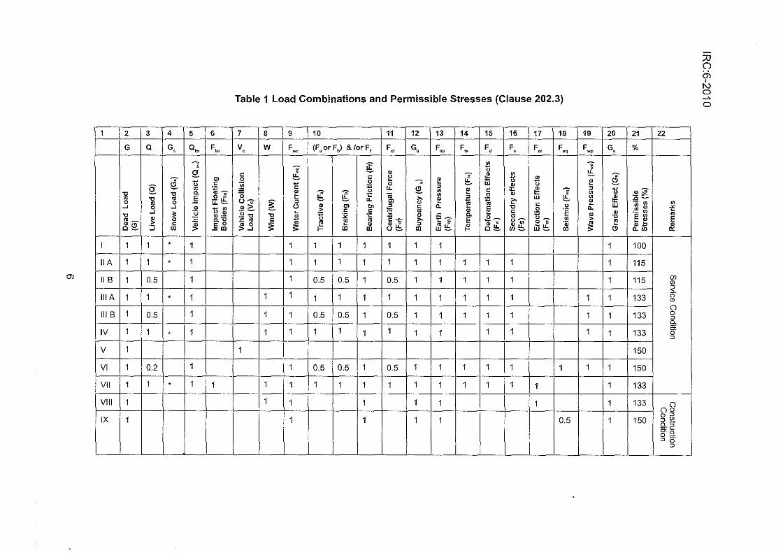
202.3 Combination of Loads and Forces and Permissible Increase in Stresses
The load combination shown in Table 1 shall be adopted for working out stresses in the members. The permissible increase of stresses in various members due to these combinations are also indicated therein. These combinations of forces are not applicable for working out base pressure on foundations for which provision made in relevant IRC Bridge Code shall be adopted. For calculating stresses in members using working stress method of design the load combination shown in Table 1 shall be adopted.
The load combination as shown in Annex B shall be adopted for limit state design approach as and when limit state design method is introduced.
' .
203 DEAD LOAD
The dead load carried by a girder _or member shall consist of the portion of the weight of the superstrus:ture (and the fixed loads carried thereon) which is supported wholly or in part by the girder or member including its own weight. The following unit weights of materials shall be used in determining loads, unless the unit weights have been determined by actual weighing of representative samples of the materials in question, in which case the actual weights as thus determined shall be used.
NOTES
1) * Where Snow Load is applicable, Clause 221 shall be referred for combination
of snow load and live load.
5
1 2 3 4 5 6
G Q G, o,. F,.
--.. Q_
~ u "' c 0 ro :;_
0. "C - "C 0 ' ro "C ro E -u. 0 ro 0 - u.-
..J 0 ..J ~ - "' ..J ~ u u ~ "C ro ·-ms ~ 0 :E o."C
-~ c !f. E o o- ..J rn -"' I 1 1 • 1
IIA 1 1 . 1
m II B 1 0.5 1
lilA 1 1 . 1
Ill B 1 0.5 1
IV 1 1 • 1
v 1
VI 1 0.2 1
VII 1 1 . 1 1
VIII 1
IX 1
Table 1 Load Combinations and Permissible Stresses (Clause 202.3)
7 8 9 10 11 12 13 14 15 16 17 18
v, w F., (FaorFb) &/orFt F., G, F., F,. F, F, F., F,,
~ -=- 1l !::. ~ c c ~ J ~ 1l 1l 0 0 -. E
~ - 0 - w ~ c :u u. ~
~
E c ~ ~ ;;: ;;: "' 0 ;£ <i "' 0 ~ u: >o !! ~
~ 1:- w u-;;- ~ ~ - - "' '§ -u c ~G () ~ "' "' ~ c a. § "C 0
u - > c c ~ ro ~ '§ -~ "C " ti J: 0.
c "' "C " :;;; ·~ E--::- 0 .e- 0
.<:: ro c ~ E >o tO: E u- ~--=- "' ~.3 ~ $ ~ ~u: ~ ro •
~ ~ " ~ "' w~ '@
Ill Ill U- Ill w!::. o!::. rn!::. rn
1 1 1 1 1 1 1
1 1 1 1 1 1 1 1 1 1
1 0.5 0.5 1 0.5 1 1 1 1 1
1 1 1 1 1 1 1 1 1 1 1
1 1 0.5 0.5 1 0.5 1 1 1 1 1
1 1 1 1 1 1 1 1 1 1
1
1 0.5 0.5 1 0.5 1 1 1 1 1 1
1 1 1 1 1 1 1 1 1 1 1 1
1 1 1 1 1 1
1 1 1 1 0.5
19 20
F G, .,
~ J E -~ u "' "' ~ !! a. w ~
~ "C > E ~ (!)
1
1
1
1 1
1 1
1 1
1 1
1
1
1
21
%
~~ .c-·-"' .~ m E "' "~ ~;, a.rn
100
115
115
133
133
133
150
150
133
133
150
22
"' ;'!; ro E ~
"'
(f) CD
s. " CD
0 0 ::> 0.
"' c;· ::>
0 oo 0 ::> ::> "' o.'< a:§ o-::I o·
::>
:;o 0 Q)
' (\.) 0 ~
0

IRC:6-2010
2) Any load combination involving temperature, wind and/or earthquake acting
independently or in combination, maximum permissible tensile stress in Prestressed
Concrete Members shall be limited to the value as per relevant Code (IRC:18).
3) Use offractionallive load 0.5 shown in the above Table is applicable only when the full
design live load given in Table 2 is considered. The structure must also be checked
with no live load.
4) The gradient effect due to temperature is considered in the load combinations liB and
IIIB. The reduced live load (Q) is indicated as 0.5. Its effects (F8
, Ft, and F,,) are also
shown as 0.5, as 0.5 stands for the reduced live load to be considered in this case.
However for F, it is shown as 1, since it has effects of dead load besides reduced live
load. O;m being a factor of live load as shown as 1. Whenever a fraction of live load 0.5
shown in the above Table under column Q is specified, the associated effects due to
live load ( O;m• F8
, Ft, F, and F,,) shall be considered corresponding to the associated
fraction of live load. When the gradient effect is considered, the effects, if any, due to
overall rise or fall of temperature of the structure shall also be considered.
5) Seismic effect during erection stage is reduced to half in load combination IX when
construction phase does not exceed 5 years.
6) The load combinations (VIII and IX) relate to the construction stage of a new bridge. For
repair, rehabilitation and retrofitting, the load combination shall be project-specific.
Materials Weight
(Um3)
1) Ashlar (granite) 2.7
2) Ashlar (sandstone) 2.4
3) Stone sells :
a) Granite 2.6
b) Basalt 2.7
4) Ballast (stone screened, broken, 2.5 em to 7.5 em
guage, loose):
a) Granite 1.4
b) Basalt 1.6
5) Brickwork (pressed) in cement mortar 2.2
6) Brickwork (common) in cement mortar 1.9
7

IRC:6-2010
7) Brickwork (common) in lime mortar 1.8
8) Concrete (asphalt) 2.2
9) Concrete (breeze) 1.4
1 0) Concrete (cement-plain) 2.5
11) Concrete (cement- plain with plums) 2.5
12) Concrete (cement-reinforced) 2.5
13) Concrete (cement-prestressed) 2.5
14) Concrete (lime-brick aggregate) 1.9
15) Concrete (lime-stone aggregate) 2.1
16) Earth (compacted) 2.0
17) Gravel 1.8
18) Macadam (binder premix) 2.2
19) Macadam (rolled) 2.6
20) Sand (loose) 1.4
21) Sand (wet compressed) 1.9
22) Coursed rubble stone masonry (cement mortar) 2.6
23) Stone masonry (lime mortar) 2.4
24) Water 1.0
25) Wood 0.8
26) Cast iron 7.2
27) Wrought iron 7.7
28) Steel (rolled or cast) 7.8
204 LIVE LOADS
204.1 Details of I.R.C. Loadings
204.1.1 For bridges classified under Clause 201.1, the design live load shall consist of standard wheeled or tracked vehicles or trains of vehicles as illustrated in Figs. 1 to 3 and Annex A. The trailers attached to the driving unit are not to be considered as detachable.
204.1.2 Within the kerb to kerb width of the roadway, the standard vehicle or train shall be assumed to travel parallel to the length of the bridge and to occupy any position which will produce maximum stresses provided that the minimum clearances between a vehicle and the roadway face of kerb and between two passing or crossing vehicles, shown in Figs. 1 to 3, are not encroached upon.
204.1.3 For each standard vehicle or train, all the axles of a unit of vehicles shall be considered as acting simultaneously in a position causing maximum stresses.
8

NOTES:
Mm. Min.
TRACKED VEHICLE
TRACKED VEHICLE
6.25 6.25
' ' ' : ~ -~~ B
PLAN
' --' ~ ' ' ' ' ~ ~i0150
!H2!I
WHEELED VEHICLE Fig. 1 Class AA Tracked and Wheeled Vehicles (Clause 204.1)
IRC:6-2010
1) The nose to tail spacing between two successive vehicles shall not be less than
90 m.
2) For multi-lane bridges and culverts, load combinations as given in Table 2 shall be adopted. Where IRC Class AA loading is specified it shall be used in place of Class 70R but nose to tail distance shall be as specified in Note No.1.
9

IRC:6-2010
3)
4)
The maximum loads for the wheeled vehicle shall be 20 tonne for a single axle or 40 tonne for a bogie of two axles spaced not more than 1.2 m centres.
The minimum clearance between the road face of the kerb and the outer edge of the wheel or track, C, shall be as under:
Carriageway width
Single- Lane Bridges Upto width of 5.3 m
Multi-Lane Bridges More than 5.3 m
Minimum value of C (m)
0.3
1.2
5) Axle loads in tonne. Linear dimensions in metre.
8.300
!:---] . r-::?. P--~.f..,J -}{-
o.i ]0.6
20.000 110 3.2001
I 1.aoo I SECTION ON P-P
1.800
-i'rr- + ·Ft-----t-1 I
-t--- 5t-" I ~I i51
p I 5 I
L I ~I
-$---1$-·t ~-----~-~ ~
PLAN DRIVING VEHICLE
1.200 1.200 4.800
I I I I -]( ·1 I ·r--1 ·]'
20 4.300 3.000 3.000
6.8 2.7 2.7 11.4 11.4 6.8 6.8
4.800
·r ·T'
3.000
6.8 6.8
Class A Train of Vehicles
{j-....-c r~L--
. -"\·"!i:·:o:"--i o.6-+
20.000 1 '"'' 2.7 2.7
Fig. 2 Class 'A' Train of Vehicles (Clause 204.1)
10

NOTES: 1)
2)
3)
IRC:6-2010
The nose to tail distance between successive trains shall not be less than 18.5 m.
For single-lane and multi-lane bridges live load combinations as given in Table 2 shall be followed.
The ground contact area of the wheels shall be as under: ,.
Axle load (tonne) Ground contact area
11.4
6.8
2.7
B(mm)
250
200
150
CLEAR CARRIAGEWAY WIDTH
. I I . . I I . 0.300 0.300 0.300
. I I . 0.300
W(mm)
500
380
200
4) The minimum clearance, f, between outer edge of the wheel and the roadway face of the kerb and the minimum clearance, g, between the outer edges of passing or crossing vehicles on multi-lane bridges shall be as given below:-
Clear carriageway width
5.5 m to 7.5 m
Above 7.5 m
g
Uniformly increasing from 0.4 m to 1.2 m 1.2 m
5) Axle loads in tonne. Linear dimensions in metre.
11
f
150 mm for all carriageway widths

JRC:6-2010
NOTES:
'---J ' ~---"":.
1 1.8oo 1
SECTION ON P-P 1.800
mt+---+ I I
-t--- Qt-1 b I' I "' I I ~ I
P I :z I I C> I I ~ I
p
L I l:il I -e--- ~e- ---+--'0
mt 4-----4- ~ lwl ,,w,
PLAN DRIVING VEHICLE
8.300 1.200 4.800 1.200 4.800 18 500
·~I I {)..,_ __
(~~-~ .'f.~~ '"'{·]-'[·]'"' '"'(.J-1" ·J'"' ."i- .• -1
0.9.,.; .. , 0.6• ~ . 0.6+4='
3.2001 20
4.300 3.000 3.000 3.000 20.000 1 00 20.000 1 0
4.1 1.6 1.6 6.8 6.8 4.1 4.1 4.1 4.1 1.6 1.6
Class B Train of Vehicles
Fig. 3 Class 'B' Train of Vehicles (Clause 204.1)
1) The nose to tail distance between successive trains shall not be Jess than
18.5 m.
12

IRC:6-2010
2) No other live load shall cover any part of the carriageway when a train of vehicles (or trains of vehicles in multi-lane bridge) is crossing the bridge.
3) The ground contact area of the wheels shall be as under:-
Axle load Ground contact area
(tonne) B(mm) W(mm)
6.8 200 380
4.1 150 300
1.6 125 175
CLEAR CARRIAGEWAY WIDTH
, I I. _I I. . I I . . I 0.300 0.300 0.300 0.300
4) The minimum clearance:s, i, between outer edge of the wheel and the roadway face of the kerb and the minimum clearance, g, between the outer edges of passing or crossing vehicles on multi-lane bridges shall be as given below:-
Clear carriageway width g f
5.5 m to 7.5 m Uniformly increasing from 150 mm for all carriageway 0.4 m to 1.2 m widths
Above 7.5 m 1.2 m
5) Axle loads in tonne. Linear dimensions in metre.
204.1.4 Vehicles in adjacent lanes shall be taken as headed in the direction producing maximum stresses.
204.1.5 The spaces on the carriageway left uncovered by the standard train of vehicles shall not be assumed as subject to any additional live load unless otherwise specified in Table 2.
204.2 Dispersion of Load through Fills of Arch Bridges
The dispersion of loads through the fills above the arch shall be assumed at 45 degrees both along and perpendicular to the span in the case of arch bridges.
13

IRC:6-2010
204.3 Combination of Live Load
This Clause shall be read in conjunction with Clause 112.1 of IRC:S. The carriageway live load combination shall be considered for the design as shown in Table 2.
Table 2 Live Load Combination
SI.No Carriageway width Number of lanes for Load combination design purposes
1) Less than 5.3 m 1 One Jane of Class A considered to occupy 2.3 m. The remaining width of carriageway slla/1 be loaded with 500 kg/m2 .,
2) 5.3 m and above but Jess 2 One Jane of Ciass ?OR OR than 9.6 m two Janes of Class A
3) 9.6 m and above but Jess 3 One Jane of Class ?OR. for than 13.1 m every two lanes with one lane
of Class A on the remaining Jane OR 3 lanes of Class A.
4) 13.1 m and above but Jess 4 than 16.6 m
One Jane of Class ?OR for
5) 16.6 m and above but Jess 5 every two Janes with one lane
than 20.1 m of Class A for the remaining lanes, if any, OR one lane of
6) 20.1 m and above but less 6 Class A for each lane. than 23.6 m
NOTES:
1) The width of the two-lane carriageway shall be 7.5 m as per Clause 112.1, of IRC:5.
2) See Note 2 under Clause 204.1.3 regarding use of ?OR loading in place of Class AA
Loading and vice-versa.
205 REDUCTION IN THE LONGITUDINAL EFFECT ON BRIDGES ACCOMMODATING MORE THAN
TWO TRAFFIC LANES
Reduction in the longitudinal effect on bridges having more than two traffic lanes due to the low probability that all lanes will be subjected to the characteristic loads simultaneously shall
14

IRC:6-2010
be in accordance with the Table shown below:
Number of lanes Reduction in longitudinal effect
For two lanes No reduction
For three lanes 10% reduction
For four lanes 20% reduction
For five or more lanes 20% reduction
NOTES:
1) However, it should be ensured that the reduced longitudinal effects are not less severe than the longitudinal effect, resulting from simultaneous loads on two adjacent lanes. Longitudinal effects mentioned above are bending moment, shear force and torsion in longitudinal direction.
2) The above Table is applicable for individually supported superstructure of multi-laned carriageway. In the case of separate sub-structure and foundations, the number of lanes supported by each of them is to be considered while working out the reduction percentage. In the case of combined sub-structure and foundations, the total number of lanes for both the carriageway is to be considered while working out the reduction percentage.
206 FOOTWAY, KERB, RAILINGS, PARAPET AND CRASH BARRIERS
The horizontal force specified for footway, kerb, railings, parapet and crash barriers in this section need not be considered for the design of main structural members of the bridge. However, the connection between kerb/railings/papapet, crash barrier and the deck should be adequately designed and detailed.
206.1 For all parts of bridge floors accessible only to pedestrians and animals and for all footways the loading shall be 400 kg/m2. Where crowd loads are likely to occur, such as, on bridges located near towns, which are either centres of pilgrimage or where large congregational fairs are held seasonally, the intensity of footway loading shall be increased from 400 kg/rn2 to 500 kg/m2• When crowd load is considered, the bridge should also be designed for the case of entire carriageway being occupied by crowd load.
206.2 Kerbs, 0.6 m or more in width, shall be designed for the above loads and for a local lateral force of 750 kg per metre, applied horizontally at top of the kerb. If kerb width is less than 0.6 m, no live load shall be applied in addition to the lateral load specified above.
15

IRC:6-2010
206.3 In bridges designed for any of the loadings described in Clause 204.1, the main girders, trusses, arches, or other members supporting the footways shall be designed for the following live loads per square metre for footway area, the loaded length of footway taken in each case being, such as, to produce the worst effects on the member under con~ideration:
where
a) For effective span of 7.5 m or less, 400 kg/m2 or 500 kg/m2 as the case may be, based on Sub-Clause 206.1.
b) For effective spans of over 7.5 m but not exceeding 30m, the intensity of load shall be determined according to the equation :
p = P'- ( 40L ; 300)
c) For effective spans of over 30 m, the intensity of load shall be determined according to the equation :
P= (p1_ 260 + 48LOO) c6·~;W)
P1 = 400 kg/m2 or 500 kg/m2 as the case may be, based on Sub-Clause 206.1.When crowd load is considered for design of the bridge, the reduction mentioned in this clause will not be applicable.
P = the live load in kg/m2
L = the effective span of the main girder, truss or arch in m, and
W =width of the footway in m
206.4 Each part of the footway shall be capable of carrying a wheel load of 4 tonne, which shall be deemed to include impact, distributed over a contact area 300 mm in diameter; the permissible working stresses shall be increased by 25 percent to meet this provision. This provision need not be made where vehicles cannot mount the footway as in the case of a footway separated from the roadway by means of an insurmountable obstacle, such as, truss or a main girder.
NOTE :A footway kerb shall be considered mountable by vehicles.
206.5 The Pedestrian/Bicycle Railings/Parapets
The pedestrian/bicycle railings/parapets can be of a large variety of construction. The design loads for two basic types are given below:-
i) Type: Solid/partially filled in parapet continuously cantilevering along full length from deck level.
16

IRC:6-2010
Loading: Horizontal and vertical load of 150 kg/m2 acting simultaneously on the top level of the parapet.
ii) Type: Frame type with discrete vertical posts cantilevering from the curb/deck with minimum two rows of horizontal rails (third row bring the curb itself, or curb replaced by a low level 3rd rail). The rails may be simply supported or continuous over the posts.
Loading: Each horizontal railing designed for horizontal and vertical load of 150 kg/m2,
acting simultaneously over the rail. The filler portion, supported between any two horizontal rails and vertical rails should be designed to .resist horizontal load of 150 kg/m2 • The posts to resist horizontal load of 150 kg x spacing between posts in metres acting on top of the post.
206.6 Crash Barriers
Crash barriers are designed to withstand the impact of vehicles of certain weights at certain angle while travelling at the specified speed. They are expected to guide the vehicle back on the road while keeping the level of damage to vehicle as well as to the barriers within acceptable limits.
Following are the three categories for different applications:
Category Application Containment for
P-1: Normal Containment Bridges carrying expressway, or 15 kN vehicle at 110 km/h, and equivalent 20° angle of impact
P-2: Low Containment All other bridges except bridge 15 kN vehicle at 80 km/h and over railways 20° angle of impact
P-3: High Containment At hazardous and high risk 300 kN vehicle at 60 km/h and locations, over busy railway 20° angle of impact lines, complex interchanges, etc.
The barriers can be of rigid type, using cast-in-situ/precast reinforced concrete panels, or of flexible type, constructed using metallic cold-rolled and/or hot-rolled sections. The metallic type, called semi-rigid type, suffer large dynamic deflection of the order of 0.9 to 1.2 m impact, whereas the 'rigid' concrete type suffer comparatively negligible deflection. The efficacy of the two types of barriers is established on the basis of full size tests carried out by the laboratories specializing in such testing. Due to the complexities of the structural action, the value of impact force cannot be quantified.
A certificate from such laboratory can be the only basis of acceptance of the semi-rigid type, in which case all the design details and construction details tested by the laboratcry are to be followed in toto without modifications and without changing relative strengths and positions of any of the connections and elements.
17

IRC:6-2010
For the rigid type of barrier, the same method is acceptable. However, in absence of testing/test certificate, the minimum design resistance shown in Table 3 should be built into the section.
Table 3 Minimum Design Resistance
SL Requirement Types of Crash Barrier No. P-1 In-situ/ P-2 In-situ/ P-3 In-situ
Precast Precast 1 ) Shape Shape on traffic side to be as per IRC:5, or New
Jersey (NJ) Type of 'F' Shape designated thus byAASHTO
2) Minimum grade of concrete M-40 M-40 M-40
3) Minimum thickness of R C 175 mm 175 mm 250 mm wall ( at top)
4) Minimum moment of 15 kNm/m 7.5 kNm/m 100 kNm/m for resistance at base of end section and the wall [see note (i)] for 75 kNm/m for bending in vertical plane with intermediate section reinforcement adjacent to the [see note (iii)] traffic face [see note (ii)]
5) Minimummomentofresistance 7.5 kNm/m 3.75 kNm/m 40 kNm/m for bending in horizontal plane with reinforcement adjacent to outer face [see note (ii)]
6) Minimum moment of 22.5 11.25 Not applicable resistance of anchorage at the kNm/m kNm/m base of a precast reinforced concrete panel
7) Minimum transverse shear 44 kN/m of 22.5 kN/m Not applicable resistance at vertical joints joint of joint between precast panels, or at vertical joints made between lengths of in-situ crash barrier.
8) Minimum height 900 mm 900 mm 1550 mm
NOTES:
i) The base of wall refers to horizontal sections of the parapet within 300 mm above the adjoining paved surface level. The minimum moments of resistance shall reduce linearly from the base of wall value to zero at top of the parapet
ii) In addition to the main reinforcement, in items 4 & 5 above, distribution steel equal to 50 percent of the main reinforcement shall be provided in the respective faces.
iii) For design purpose the crash barrier Type P-3 shall be divided into end sections extending a distance not greater than 3.0 m from ends of the crash barrier and intermediate sections extending along remainder of the crash barrier.
18

IRC:6-2010
iv) If concrete barrier is used as a median divider, the steel is required to be placed on both sides.
v) In case of P-3 In-situ type, a minimum horizontal transverse shear resistance of 135 kN/m shall be provided.
206.7 Vehicle Barriers/Pedestrian Railing between Footpath and Carriageway
Where considerable pedestrian traffic is expected, such as, in/near townships, rigid type of reinforced concrete crash barrier should be provided separating the vehicular traffic from the same. The design and construction details should be as per Clause 206.6. For any other type of rigid barrier, the strength should be equivalent to that of rigid RCC type.
For areas of low intensity of pedestrian traffic, semi-rigid type of barrier, which suffers large deflections can be adopted.
207 TRAMWAY lOADING
207.1 When a road bridge carries tram lines, the live load due to the type of tram cars sketched in Fig. 4 shall be computed and shall be considered to occupy a 3 m width of roadway.
207.2 A nose to tail sequence of the tram cars or any other sequence which produces the heaviest stresses shall be considered in the design.
I I i I I I i I I i i I I n Tikjoo I I lj'· JJd / i " r------~dso------;------- ~ i " i 1 I
. 1 .L ' cp \I; I L,,,oo-' I L,.sol>-' I
6.141)-------- ' ,14 ' 12.28
BOGIES CAR (SINGLE CECI\)
f-L-1-.LLLJ..I-LLJ,· ui...LL.LLll-'-1 J + ~~ . ~-·:. a1 JJ ~~~ ~~~( L.~~
Fig. 4 Average Dimension of Tramway Rolling Stock (Clause 207.1)
19

IRC:6-2010
NOTES:
1) Clearance between passing single deck bogie cars on straight tracks laid at standard 2.75 m track centres shall be 300 mm.
2) Clearance between passing double bogie cars on straight tracks laid at standard 2.75 m track centres shall be 450 mm.
3) Linear dimensions in metre.
ROLLING STOCK WEIGHT
Description Loaded weight (tonne) Unloaded weight (tonne)
Single truck (Single deck) 9.6 7.9
Bogie car (Single deck) 1 '· 12.2
Bogie car (Double deck) 21.5 16.0
207.3 Stresses shall be calculated for the following two conditions and the maximum thereof considered in the design.
a) Tram loading, followed and preceded by the appropriate standard loading
specified in Clause 204.1 together with that standard loading on the traffic lanes
not occupied by the tram car lines.
b) The appropriate standard loading specified in Clause 204.1 without any tram cars.
208 IMPACT
208.1 Provision for impact or dynamic action shall be made by an increment of the live load by an impact allowance expressed as a fraction or a percentage of the applied live load.
208.2 For Class A or Class B Loading
In the members of any bridge designed either for Class A or Class B loading (vide Clause 204.1 ), this impact percentage shall be determined from the curves indicated in Fig.5. The impact fraction shall be determined from the following equations which are applicable for spans between 3 m and 45 m.
i) Impact factor fraction for reinforced concrete bridges
ii) Impact factor fraction for steel bridges
20
4.5
6+L
9 = -:-::--:::---:-
13.5 +L

IRC:G-2010
Where L is length in metres of the span as specified in Clause 208.5
208.3 For Class AA Loading and Class 70R Loading
The value of the impact percentage shall be taken as follows:-
a) For spans less than 9 m :
1) for tracked vehicles
2) for wheeled vehicles
(b) For spans of 9 m or more :
i) Reinforced concrete bridges
1) Tracked vehicles
2) Wheeled vehicles
ii) Steel bridges
25 percent for spans upto 5 m linearly reducing to 10 percent for spans of 9 m
25 percent
10 percent upto a span of 40 ·m and in accordance with the curve in Fig. 5 for spans in excess of 40 m.
25 percent for spans upto 12 m and in accordance with the curve in Fig. 5 for spans in excess of 12m.
3) Tracked vehicles 10 percent for all spans
4) Wheeled vehicles 25 percent for spans upto 23 m and in accordance with the curve indicated in Fig. 5 for spans in excess of 23 m.
208.4 No impact allowance shall be added to the footway loading specified in Clause 206.
60
55
50
45
40 • "' .!! c 35
• ~ 30 • ll.
0 :1 25 .§
20
15
10
5
0
0
50 PERCENT FOR SPANS OF 3m OR~ ~.; PERCENTFO~ 3m OR LESS
~ Curve for Concretel Bridges
C""" foe Steel Bcid te'
PAr OF 45m OR MORE I
8.8 JT FOR SPANS OF 45m OR MORE (
3 6 9 12 15 18 21 24 27 30 33 36 39 42 45 48 51 54 57
Span in Metre
Fig. 5 Impact Percentage for Highway Bridges for Class A and Class B Loading (Clause 208.2)
21

IRC:6-2010
208.5 The span length to be considered for arriving at the impact percentages specified in Clause 208.2 and 208.3 shall be as follows:
a) For spans simply supported or continuous or for arches the effective span on which the load is placed.
b) For bridges having cantilever arms without suspended spans ................ . the effective overhang of the cantilever arms reduced by 25 percent for loads on the cantilever arms and the effective span between supports for loads on the main span.
c) For bridges having cantilever arms with suspended span ....................... . the effective overhang of the cantilever arm plus half the length of the suspended span for loads on the cantilever arm, the effective length of the suspended span for loads on the suspended span and the effective span between supports for load on the main span.
NOTE: "For individual members of a bridge, such as, a cross girder or deck slab, etc. the value of L mentioned in Clause 208.2 or the spans mentioned in clause 208.3 shall be the effective span of the member under consideration".
208.6 In any bridge structure where there is a filling of not less than 0.6 m including the road crust, the impact percentage to be allowed in the design shall be assumed to be onehalf of what is specified in Clauses 208.2 and 208.3.
208.7 For calculating the pressure on the bearings and on the top surface of the bed blocks, full value of the appropriate impact percentage shall be allowed. But, for the design of piers abutments and structures, generally below the level of the top of the bed block, the appropriate impact percentage shall be multiplied by the factor given below:
a) For calculating the pressure at the bottom surface of the bed block
b) For calculating the pressure on the top 3 m of the structure below the bed block
c) For calculating the pressure on the portion of the structure more than 3 m below the bed block
22
0.5
0.5 decreasing uniformly to zero
zero
IRC:6-2010
208.8 In the design of members subjected to among other stresses, direct tension, such
as, hangers in a bowstring girder bridge and in the design of member subjected to direct
compression, such as, spandrel columns or walls in an open spandrel arch, the impact
percentage shall be taken the same as that applicable to the design of the corresponding
member or members of the floor system which transfer loads to the tensile or compressive
members in question.
208.9 These Clauses on impact do not apply to the design of suspension bridges. In
cable suspended bridges and in other bridges where live load to dead load ratio is high, the
dynamic effects, such as, vibration and fatigue shall be considered.
209 WIND LOAD
209.1 This clause is applicable to normal span bridges with individual span length up to
150 m or for bridges with height of pier up to 100 m. For all other bridges including cable
stayed bridges, suspension bridges and ribbon bridges specialist literature shall be used for
computation of design wind load.
209.1.1 The wind pressure acting on a bridge depends on the geographical locations,
the terrain of surrounding area, the fetch of terrain upwind of the site location, the local
topography, the height of bridge above the ground, horizontal dimensions and cross-section
of bridge or its element under consideration. The maximum pressure is due to gusts that
cause local and transient fluctuations about the mean wind pressure.
All structures shall be designed for the following wind forces. These forces shall be considered
to act in su_9h a direction that the resultant stresses in the member under consideration are
maximum.
In addition to applying the prescribed loads in the design of bridge elements, stability against
overturning, uplift and sliding due to wind shall be considered.
209.2 The wind speed at the location of bridge shall be based on basic wind speed map as
shown in Fig. 6. The intensity of wind force shall be based on hourly mean wind speed and
pressure as shown in Table 4. The hourly mean wind speed and pressure values given in
Table 4 corresponds to a basic wind speed of 33 m/s, return period of 1 00 years, for bridges
situated in plain terrain and terrain with obstructions, with a flat topography. The hourly mean
wind pressure shall be appropriately modified depending on the location of bridge for other
23

IRC:6-2000
basic wind speed as shown in Fig. 6 and used for design(see notes below Table 4).
Table 4 Hourly Mean Wind Speed And Wind Pressure (For a basic wind speed of 33 m/s as shown in Fig. 6)
Bridge situated in
H (m) Plain terrain Terrain with obstructions
V, (m/s) P, (N/m') V, (m/s) P, (N/m')
Upto10m 27.80 463.70 17.80 190.50
15 29.20 512.50 19.60 230.50
20 30.30 550.60 21.00 265.30
30 31.40 590.20 22.80 312.20
50 33.10 659.20 24.90 3/::;.40
60 33.60 676.30 25.60 392.90 70 34.00 693.60 26.20 412.80
80 34.40 711.20 26.90 433.30
90 34.90 729.00 27.50 454.20 100 35.30 747.00 28.20 475.60
H = the average height in metres of exposed surface above the mean retarding surface (ground or bed or water level)
V, = hourly mean speed of wind in m/s at height H
P, = horizontal wind pressure in N/m2 at height H
NOTES:
1) Intermediate values may be obtained by linear interpolation.
2) Plain terrain refers to open terrain with no obstruction or with very well scattered obstructions having height up to 10m. Terrain with obstructions refers to a terrain with numerous closely spaced structures, forests or trees upto 10 m in height with few isolated tall structures or terrain with large number of high closed spaced obstruction like structures, trees forests etc.
3) For other values of basic wind speed as indicated in Fig. 6, the hourly mean wind speed shall be obtained by multiplying the corresponding wind speed value by the ratio of basic wind speed at the location of bridge to the value corresponding to Table 4, (i.e., 33 m/sec.)
4) The hourly mean wind pressure at an appropriate height and terrain shall be obtained by multiplying the corresponding pressure value for base wind speed as indicated in Table 4 by the ratio of square of basic wind speed at the location of wind to square of base wind speed corresponding to Table 4 (i.e., 33m/sec).
5) If the topography (hill, ridge escarpment or cliff) at the structure site can cause acceleration or funneling of wind, the wind pressure shall be further increased by 20 percent as stated in Note 4.
6) For construction stages, the hourly mean wind pressure shall be taken as 70 percent of the value calculated as stated in Note 4 and 5.
24

IRC:6-2010
209.3 Design Wind Force on Superstructure
209.3.1 The superstructure shall be designed for wind induced horizontal forces (acting in the transverse and longitudinal direction) and vertical loads acting simultaneously. The assumed wind direction shall be perpendicular to longitudinal axis for a straight structure or to an axis chosen to maximize the wind induced effects for a structure curved in plan.
209.3.2 The transverse wind force on a bridge superstructure shall be estimated as specified in Clause 209.3.3 and acting on the area calculated as follows:
a) For a deck structure:
The area of the structure as seen in elevation including the floor system and railing, less area of perforations in hand railing or parapet walls shall be considered. For open and solid parapets, crash barriers and railings, the solid area in normal projected elevation of the element shall be considered.
b) For truss structures:
Appropriate area as specified in Annex C shall be taken.
c) For construction stages
The area at all stages of construction shall be the appropriate unshielded solid area of structure.
209.3.3 The transverse wind force F T (in N) shall be taken as acting a-t the centroids of the appropriate areas and horizontally and shall be estimated from:
FT = P2 xA1 x G x CD
where, P2
is the hourly mean wind pressure in N/m2 (see Table 4 ), A1
is the solid area in m2
(see Clause 209.3.2), G is the gust factor and CD is the drag coefficient depending on the geometric shape of bridge deck.
For highway bridges up to a span of 150 m, which are generally not sensitive to dynamic 2ction of wind, gust factor shall be taken as 2.0.
The drag coefficient for slab bridges with width to depth ratio of cross-section, i.e bid <:: 10 shall be taken as 1.1.
For bridge decks supported by single beam or box girder, CD shall be taken as 1.50 for bid ratio of 2 and as 1.3 if bid<:: 6. For intermediate bid ratios CD shall be interpolated. For deck supported by two or more beams or box girder it shall be taken as 1.5 times CD for the single beam or box, however the value shall not be less than 1.3.
For deck supported by single plate girder it shall be taken as 2.2. When the deck is supported by two or more plate girders, for the combined structure C0 shall be taken as 2(1 +c/20d), but not more than 4, where c is the centre to centre distance of adjacent girders, and d is the depth of windward girder.
For truss girder superstructure the drag coefficients shall be derived as given in Annex D.
For other type of deck cross-sections CD shall be ascertained either from wind tunnel tests or, if available, for similar type of structure, specialist literature shall be referred to.
27

IRC:6-2010
209.3.4 The longitudinal force on bridge superstructure FL (in N) shall be taken as 25 percent and 50 percent of the transverse wind load as calculated as per Clause 209.3.3 for beam/ box/plate girder bridges and truss girder bridges respectively.
209.3.5 An upward or downward vertical wind load Fv (in N) acting at the centroid of the appropriate areas, for all superstructures shall be derived from:
where
Fv=PzxA 3 xGxCL
Pz is the hourly mean wind pressure in N/m2 at height H (see Table 4)
A3
is the area in plan in m2
CL is the lift coefficient which shall be taken as 0.75 for normal type of ~:ab, box, 1-girder and plate girder bridges. For other type of deck cross-sections CL shall be ascertained either from wind tunnel tests or, if available, for similar type of structure. Specialist literature shall be referred to.
G is the gust factor as defined in 209.3.3
209.3.6. The transverse wind load per unit exposed frontal area of the live load shall be computed using the expression F
7 given in Clause 209.3.3 except that C0 against shall
be taken as 1.2. The exposed frontal area of live load shall be the entire length of the superstructure seen in elevation in the direction of wind as defined in clause or any part of that length producing critical response, multiplied by a height of 3.0 m above the road way surface. Areas below the top of a solid barrier shall be neglected.
The longitudinal wind load on live load shall be taken as 25 percent of transverse wind load as calculated above. Both loads shall be applied simultaneously acting at 1.5 m above the roadway.
209.3. 7 The bridges shall not be considered to be carrying any live load when the wind speed at deck level exceeds 36 m/s.
209.3.8 In case of cantilever construction an upward wind pressure of Pz x CL x G N/m2 (see Clause 209.3.5 for notations) on bottom soffit area shall be assumed on stabilizing cantilever arm in addition to the transverse wind effect' calculated as per Clause 209.3.3. In addition to the above, other loads defined in clause 218.3 shall also be taken in to consideration.
209.4 Design Wind Forces on Substructure
The substructure shall be designed for wind induced loads transmitted to it from the superstructure and wind loads acting directly on the substructure. Loads for wind directions both normal and skewed to the longitudinal centerline of the superstructure shall be considered.
F 7 shall be computed using expression in Clause 209.3.3 with A1 taken as the solid area in
normal projected elevation of each pier. No allowance shall be made for shielding.
For piers, C0
shall be taken from Table 5. For piers with cross-section dissimilar to those given in Table 5, C
0 shall be ascertained either from wind tunnel tests or, if available, for
28

IRC:6-2010
similar type of structure, specialist literature shall be referred to C0 shall be derived for each pier, without shielding.
Table 5 Drag Coefficients C0
For Piers
CD FOR PIER HEIGHT
RATIOS OF BREADTH
PLAN SHAPE
I 1 2 4 6 10 20 40 b
WIND - ~b 1 1.3 1.4 1.5 1.6 1.7 1.9 2.1 <--,
1 - D 3 1.3 1.4 1.5 1.6 1.8
1 2.0 2.2
2
- D 2 1.3 1.4 1.5 1.6 1.8 2.0
3 2.2
_.,. D 1 1.2 1.3 1.4 1.5 1.6 1.8 2.0
- D ,.!. 1.0 1.1 1.2 1.3 1.4 1.5 1.7 2
- I I 2 0.8 0.9 1.0 1.1 1.2 1.3 1.4
-I I 3 0.8 0.8 0.8 0.9 0.9 1.0 1.2
EJI >4 0.8 0.8 0.8 0.9 0.9 0.9 1.1 -0 SQUARE ~
OR_.,. OCTAGONAL
1.0 1.1 1.2 1.3 1.4 1.4 1.4
0 12 SIDE POLYGON
0.7 0.8 0.9 0.9 1.0 1.1 1.3
Q CIRCLE WITH SMOOTH SURFACE HERE tVz~6m2 /S
0.5 0.5 0.5 0.5 0.5 0.6 0.6
Q CIRCLE WITH SMOOTH SURFACE WHERE tVz>6m 2 /S CIRCLE WITH ROUGH SURFACE OR WITH PROJECTIONS 0.7 0.7 0.8 0.8 0.9 1.0 1.2
29

IRC:6-2010
NOTES:
1) For rectangular piers with rounded corners with radius r, the value of C0 derived from Table 5 shall be multiplied by (1-1.5 rib) or 0.5, whichever is greater.
2) For a pier with triangular nosing, C0 shall be derived as for the rectangle encompassing the outer edges of pier.
3) For pier tapering with height, C0 shall be derived for each of the unit heights into which the support has been subdivided. Mean values oft and b for each unit height shall be used to evaluate tlb. The overall pier height and mean breadth of each unit height shall be used to evaluate height/breadth.
4) After construction of the superstructure C0
shall be derived for height to breadth ratio of 40.
209.5 Wind Tunnel Testing
Wind tunnel testing by established procedures shall be conducted for dynamically sensitive structures such as cable stayed, suspension bridges etc., including modeling of appurtenances.
210 HORIZONTAL FORCES DUE TO WATER CURRENTS
210.1 Any part of a road bridge which may be submerged in running water shall be designed to sustain safely the horizontal pressure due to the force of the current.
210.2 On piers parallel to the direction of the water current, the intensity of pressure shall be calculated from the following equation:
where
P= 52KV
P = intensity of pressure due to water current, in kg/m2
V = the velocity of the current at the point where the pressure intensity is being calculated, in metre per second, and
K = a constant having the following values for different shapes of piers illustrated in Fig. 7
i) Square ended piers (and for the superstructure) 1.50
ii) Circular piers or piers with semi-circular ends 0.66
iii) Piers with triangular cut and ease waters, the angle included between the faces being 30° or less 0.50
30

iv) Piers with triangular cut and ease waters, the angle included between the faces being more than 30°
IRC:6-2010
but less than 60° 0.50 to 0.70
v) -do- 60 to goo 0.70 to o.go
vi) Piers with cut and ease waters of equilateral arcs of circles 0.45
vii) Piers with arcs of the cut and ease waters intersecting at goo 0.50
30'
D Piers with square ends
Circular piers or piers with semicircular ends
Piers with triangular cut and ease waters, the angle included between the faces being 30 degrees or less
Piers with triangular cut and ease waters, the angle included between the faces being more than 30 degrees but less than 60 degrees
Piers with triangular cut and ease waters, the angle included between the faces being 60 to 90 degrees
Piers with cut and ease waters of equilateral arcs of circles
Piers with arcs of the cut and ease waters intersecting at 90 degrees
Fig. 7 Shapes of Bridge Piers (Clause 21 0.2)
31

IRC:6-2010
210.3 The value of V2 in the equation given in Clause 210.2 shall be assumed to vary linearly from zero at the point of deepest scour to the square of the maximum velocity at the free surface of water. The maximum velocity for the purpose of this sub-clause shall be assumed to be -!2 times the maximum mean velocity of the current.
where
Free surface of water
u'
POINT OF DEEPEST SCOUR
-2
Square of velocity at a height 'X' from the point of deepest Scour= U2 = 2 V X H
V is the maximum mean velocity.
210.4 When the current strikes the pier at an angle, the velocity of the current shall be resolved into two components - one parallel and the other normal to the pier.
a) The pressure parallel to the pier shall be determined as indicated in Clause 210.2 taking the velocity as the component of the velocity of the current in a direction parallel to the pier.
b) The pressure of the current, normal to the pier and acting on the area of the side elevation of the pier, shall be calculated similarly taking the velocity as the component of the velocity of the current in a direction normal to the pier, and the constant K as 1.5, except in the case of circular piers where the constant shall be taken as 0.66
210.5 To provide against possible variation of the direction of the current from the direction assumed in the design, allowance shall be made in the design of piers for an extra variation in the current direction of 20 degrees that is to say, piers intended to be parallel to the direction of current shall be designed for a variation of 20 degrees from the normal direction of current and piers originally intended to be inclined at 8 degree to the direction of the current shall be designed for a current direction inclined at (20±8) degrees to the length of the pier.
210.6 In case of a bridge having a pucca floor or having an inerodible bed, the effect of cross-currents shall in no case be taken as less than that of a static force due to a difference of head of 250 mm between the opposite faces of a pier.
210.7 When supports are made with two or more piles or trestle columns, spaced closer than three times the width of piles/columns across the direction of flow, the group shall be
32

IRC:6-2010
treated as a solid rectangle of the same overall length and width and the value of K taken as 1 .25 for calculating pressures due to water currents, both parallel and normal to the pier. If such piles/columns are braced, then the group should be considered as a solid pier, irrespective of the spacing of the columns.
211 LONGITUDINAL FORCES
211.1 In all road bridges, provision shall be made for longitudinal forces arising from any one or more of the following causes:
a) Tractive effort caused through acceleration of the driving wheels;
b) Braking effect resulting from the application of the brakes to braked wheels; and
c) Frictional resistance offered to the movement of free bearings due to change of temperature or any other cause.
NOTE :Braking effect is invariably greater than the tractive effort.
211.2 The braking effect on a simply supported span or a continuous unit of spans or on any other type of bridge unit shall be assumed to have the following value:
a) In the case of a single lane or a two lane bridge : twenty percent of the first train load plus ten percent of the load of the succeeding trains or part thereof, the train loads in one lane only being considered for the purpose of this subclause. Where the entire first train is not on the full span, the braking force shall be taken as equal to twenty percent of the loads actually on the span or continuous unit of spans.
b) In the case of bridges having more than two-lanes: as in (a) above for the first two lanes plus five per cent of the loads on the lanes in excess of two.
NOTE : The loads in this Clause shall not be increased on account of impact.
211.3 The force due to braking effect shall be assumed to act along a line parallel to the roadway and 1.2 m above it. While transferring the force to the bearings, the change in the vertical reaction at the bearings should be taken into account.
211.4 The distribution oflongitudinal horizontal forces among bridge supports is effected by the horizontal deformation of bridges, flexing of the supports and rotation of the foundations. For spans resting on stiff supports, the distribution may be assumed as given below in Clause 211.5. For spans resting on flexible supports, distribution of horizontal forces may be carried out according to procedure given below in Clause 2·11.6.
211.5 Simply Supported and Continuous Spans gn Unyielding Supports
211.5.1 Simply supported spans on unyielding supports
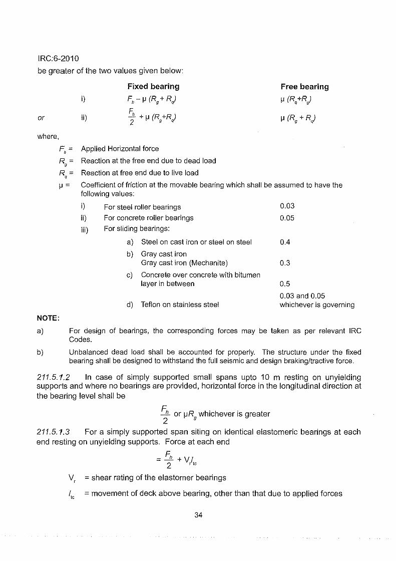
211.5.1.1 For a simply supported span with fixed and free bearings (other than elastomeric type) on stiff supports, horizontal forces at the bearing level in the longitudinal direction shall
33
IRC:6-2010
be greater of the two values given below:
or
where,
i)
ii)
Fixed bearing
F"- J.l (Rg + R,)
F. _l1_ + J.l (R +R l 2 g ql
F, = Applied Horizontal force
R = Reaction at the free end due to dead load g
R = Reaction at free end due to live load q
Free bearing
J.l (Rq +R,)
J.l (Rg + R,)
J.l = Coefficient of friction at the movable bearing which shall be assumed to have the following values:
i) For steel roller bearings 0.03
ii) For concrete roller bearings 0.05
iii) For sliding bearings:
a) Steel on cast iron or steel on steel 0.4
b) Gray cast iron Gray cast iron (Mechanite) 0.3
c) Concrete over concrete with bitumen layer in between 0.5
0.03 and 0.05 d) Teflon on stainless steel whichever is governing
NOTE:
a) For design of bearings, the corresponding forces may be taken as per relevant IRC Codes.
b) Unbalanced dead load shall be accounted for properly. The structure under the fixed bearing shall be designed to withstand the full seismic and design braking/tractive force.
211.5.1.2 In case of simply supported small spans upto 10 m resting on unyielding supports and where no bearings are provided, horizontal force in the longitudinal direction at the bearing level shall be
Fh or !JR whichever is greater 2 g
211.5.1.3 For a simply supported span siting on identical elastomeric bearings at each end resting on unyielding supports. Force at each end
= Fh +VI 2 r tc
V, = shear rating of the elastomer bearings
/10
= movement of deck above bearing, other than that due to applied forces
34

IRC:6-2010
211.5. 1.4 The substructure and foundation shall also be designed for 10 percent variation in movement of the span on either side.
211.5.2 For continuous bridges with one fixed bearing or other free bearings:
Fixed bearing Free bearing
Case-/
(~R- ~L) +ve Fh acting in +ve direction
(a) 11Fh>2~R
Fh- (~R + ~L) ~Rx
(b) lfFh < 2~R
Fh + (~R- ~L) 1+ I:nR
Cas e-ll
(~R- ~L) +ve Fh acting in -ve direction
(a) lfFh>2~L
F,- (~R + ~L)
(b) lfFh < 2~L ~Rx
Fh 1 + I:nL
+ (~R- ~L)
whichever is greater
where nL or nR = number of free bearings to the left or right of fixed bearings,respectively
~Lor J.JR = the total horizontal force developed at the free bearings to the left or right of the fixed bearing respectively
J.JRx =the net horizontal force developed at any one of the free bearings considered to the left or right of the fixed bearings
NOTE : In seismic areas, the fixed bearing shall also be checked for full seismic force and braking/ tractive force. The structure under the fixed bearing shall be designed to withstand the full seismic and design braking/tractive force.
211.6 Simply Supported and Continuous Spans on Flexible Supports
211.6.1 Shear rating of a support is the horizontal force required to move the top of the support through a unit distance taking into account horizontal deformation of the bridges, flexibility of the support and rotation of the foundation. The distribution of 'applied' longitudinal horizontal forces (e.g., braking, seismic, wind etc.) depends solely on shear ratings of the supports and may be estimated in proportion to the ratio of individual shear ratings of a support to the sum of the shear ratings of all the supports.
35

IRC:6-2010
211.6.2 The distribution of self-induced horizontal force caused by deck movement (owing to temperature, shrinkage, creep, elastic shortening, etc.) depends not only on shear ratings of the supports but also on the location of the 'zero' movement point in the deck. The shear rating of the supports, the distribution of applied and self-induced horizontal force and the determination of the point of zero movement may be made as per recognized theory for which reference may be made to publications on the subjects.
211.7 The effects of braking force on bridge structures without bearings, such as, arches, rigid frames, etc., shall be calculated in accordance with approved methods of analysis of indeterminate structures.
211.8 The effects of the longitudinal forces and all other horizontal forces should be calculated upto a level where the resultant passive earth resistance of the soil below the deepest scour level (floor level in case of a bridge having pucca floor) balances these forces.
212 CENTRIFUGAL FORCES
212.1 Where a road bridge is situated on a curve, all portions of the structure affected by the centrifugal action of moving vehicles are to be proportioned to carry safely the stress induced by this action in addition to all other stress to which they may be subjected.
212.2 The centrifugal force shall be determined from the following equation:
where
WV 2
C=--127R
C = Centrifugal force acting normally to the traffic (1) at the point of action of the wheel loads or (2) uniformly distributed over every metre length on which a uniformly distributed load acts, in tonnes.
W = Live load (1) in case of wheel loads, each wheel load being considered as acting over the ground contact length specified in Clause 204, in tonnes, and (2) in case of a uniformly distributed live load, in tonnes per linear metre.
V = The design speed of the vehicles using the bridge in km per hour, and
R = The radius of curvature in metres.
212.3 The centrifugal force shall be considered to act at a height of 1.2 m above the level of the carriageway.
212.4 No increase for impact effect shall be made on the stress due to centrifugal action.
36
IRC:6-2010
212.5 The overturning effect of the centrifugal force on the structure as a whole shall also be duly considered.
213 BUOYANCY
213.1 In the design of abutments, especially those of submersible bridges, the effects of buoyancy shall also be considered assuming that the fill behind the abutments has been removed by scour.
213.2 To allow for full buoyancy a reduction is made in the gross weight of the member affected, in the following manner:
a) When the member under consideration displaces water only, e.g., a shallow pier or abutment pier founded at or near the bed level, the reduction in weight shall be equal to that of the volume of the displaced water.
b) When the member under consideration displaces water and also silt or sand, e.g., a deep pier or abutment pier passing through strata of sand and silt and founded on similar material, the upward pressure causing the reduction in weight shall be considered as made up of two factors:
i) Full hydrostatic pressure due to a depth of water equal to the difference in levels between the free surface of water and the foundation of the member under consideration, the free surface being taken for the worst condition; and
ii) Upward pressure due to the submerged weight of the silt or sand calculated in accordance with Rankine's theory for the appropriate angle of internal friction.
213.3 In the design of submerged masonry or concrete structures, the buoyancy effect through pore pressure may be limited to 15 percent of full buoyancy.
213.4 In case of submersible bridges, the full buoyancy effect on the superstructure shall be taken into consideration.
214 EARTH PRESSURE
214.1 Structures designed to retain earth fills shall be proportioned to withstand pressure calculated in accordance with any rational theory. Coulomb's theory shall be acceptable, subject to the modification that the centre of pressure exerted by the backfill, when considered dry, is located at an elevation of 0.42 of the height of the wall above the base instead of 0.33 of that height. No structures shall, however, be designed to withstand a horizontal pressure less than that exerted by a fluid weighing 480 kg/m3. All abutments and return walls shall be designed for a live load surcharge equivalent to 1.2 m earth fill.
214.2 Reinforced concrete approach slab with 12 mm dia 150 mm c/c in each direction both at top and bottom as reinforcement in M30 grade concrete covering the entire width of
37

IRC:6-2010
the roadway, with one end resting on the structure designed to retain earth and extending for a length of not less than 3.5 m into the approach shall be provided.
214.3 All designs shall provide for the thorough drainage of backfilling materials by means of weep holes and crushed rock or gravel drains, or pipe drains, or perforated drains.
214.4 The pressure of submerged soils (not provided with drainage arrangements) shall be considered as made up of two components:
a) Pressure due to the earth calculated in accordance with the method laid down in Clause 214.1, the unit weight of earth being reduced for buoyancy, and
b) Full hydrostatic pressure of water
215 TEMPERATURE
215.1 General
Daily and seasonal fluctuations in shade air temperature, solar radiation, etc. cause the following:
a) Changes in the overall temperature of the bridge, referred to as the effective bridge temperature. Over a prescribed period there will be a minimum and a maximum, together with a range of effective bridge temperature, resulting in loads and/or load effects within the bridge due to:
i) Restraint offered to the associated expansion/contraction by the form of construction (e.g., portal frame, arch, flexible pier, elastomeric bearings) referred to as temperature restraint; and
ii) Friction at roller or sliding bearings referred to as frictional bearing restraint;
b) Differences in temperature between the top surface and other levels through the depth of the superstructure, referred to as tern perature difference and resulting in associated loads and/or load effects within the structure.
Provisions shall be made for stresses or movements resulting from variations in the temperature.
215.2 Range of Effective Bridge Temperature
Effective bridge temperature for the location of the bridge shall be estimated from the isotherms of shade air temperature given on Figs. 8 and 9. Minimum and maximum effective bridge temperatures would be lesser or more respectively than the corresponding minimum and maximum shade air temperatures in concrete bridges. In determining load effects due to temperature restraint in concrete bridges the effective bridge temperature when the structure is effectively restrained shall be taken as datum in calculating the expansion up to the maximum effective bridge temperature and contraction down to the minimum effective bridge temperature.
38

IRC:6-2010
68 72 76
68
32
28
24
20
16
12
I 8
=!
68 72 76
80 84 88
80 84
92 96
PROJECTION: LAMBERT CONICAL ORTHOMORPHIC
88
.~ II
92
32
24
8
The territorial waters of India extend into the sea to a distance of twelve nautical miles measured from the appropriate base line.
Based upon Survey of India map with permission of the Surveyor General of India.
©Government of India Copyright 1993
Responsibility for the correctness of internal details rests with the publishers.
Fig. 8 Chart Showing Highest Maximum Temperature
39

IRC:6-2010
68 72 76 80 84
28
68 72 76 80 84
88 92 98
SHOWING L WEST MAXIMUM
1 TEMPERAT RE ISOPLETHS oc
B SED ON DATA P TO 1958 SUPPLIED BY INDIA ETROLOGJCAL I DEP RTMENT
I PROJECTION: LAMBERT CONICAL ORTH MORPHIC
The territorial waters of India extend into the sea to a distance of twelve nautical miles measured from the appropriate base line. Based upon Survey of India map with permission of the Surveyor General of India © Government of India copyright 1993.
Responsibility for the correctness of internal details rests with the publishers.
Fig. 9 Chart Showing Lowest Minimum Temperature
40
88

IRC:6-2010
The bridge temperature when the structure is effectively restrained shall be estimated as follows:
Bridge location having difference between Bridge temperature to be assumed when the maximum and minimum air shade temperature structur e is effectively restrained
> 20°C Mean of maximum and minimum air shade temperature ± 10 oc whichever is critical
< 2ooc Mean of maximum and minimum air shade temperature ± 5 oc whichever is critical
For metallic structures the extreme range of effective bridge temperature to be considered in the design shall be as follows :
1) Snowbound ctreas from - 35°C to + 50°C
2) For other areas (Maximum air shade temperature+ 15°C) to (minimum air shade temperature- 1 0°C). Air shade temperatures are to be obtained from Figs. 8 and 9.
215.3 Temperature Differences
Effect of temperature difference within the superstructure shall be derived from positive temperature differences which occur when conditions are such that solar radiation and other effects cause a gain in heat through the top surface of the superstructure. Conversely, reverse temperature differences are such that heat is lost from the top surface of the bridge deck as a result of re-radiation and other effects. Positive and reverse temperature differences for the purpose of design of concrete bridge decks shall be assumed as shown in Fig. 10 (a). These design provisions are applicable to concrete bridge decks with about 50 mm wearing surface. So far as steel and composite decks are concerned, Fig. 10 (b) may be referred for assessing the effect of temperature gradient.
Positive Temperature Differences Reverse Temperature Differences
I h,
L 210
l h,
h
--, h,
---j h,
_j
h1
= 0.3h < 0.15 m
h2
= 0.3h > 0.10 m
< 0.25 m
h3
= 0.3h < 0.15 m
h1 = h4 = 0.2h < 0.25 m
h2
= h3
= 0.25h < 0.25 m
Fig. 10 (a) Design Temperature Differences for Concrete Bridge Decks
41

IRC:6-2010 50 mm surfacing
j
~r:sr·········~·········· T.
"I h.= 0.6h •. ......... h, = 0.4m
0.2 18 H(m)
0.3 20.5
h (m) 0.2 4.4 0.3 6.8
Fig. 10 (b) Temperature Differences Across Steel and Composite Section
NOTE: For intermediate slab thickness, T1
may be interpolated.
215.4 Material Properties
For the purpose of calculating temperature effects, the coefficient of thermal expansion for -6
RCC, PSC and steel structures may be taken as 12.0 x 10 /°C.
215.5 Permissible Increase in Stresses and Load Combinations
Tensile stresses resulting from temperature effects not exceeding in the value of two third of the modulus of rupture may be permitted in prestressed concrete bridges. Sufficient amount of non-tensioned steel shall, however, be provided to control the thermal cracking. Increase in stresses shall be allowed for calculating load effects due to temperature restraint under load combinations.
NOTE: Permissible increase in stresses and load combinations as stated under Clause 215.5 is not applicable for Limit State Design of Bridges.
216 DEFORMATION STRESSES (for steel bridges only)
216.1 A deformation stress is defined as the bending stress in any member of an open web-girder caused by the vertical deflection of the girder caused by the vertical deflection of the girder combined with the rigidity of the joints. No other stresses are included in this definition.
216.2 All steel bridges shall be designed, manufactured and erected in a manner such that the deformation stresses are reduced to a minimum. In the absence of calculation, deformation stresses shall be assumed to be not less than 16 percent of the dead and live loads stresses.
216.3 In prestressed girders of steel, deformation stresses may be ignored.
42

IRC:6-2010
217 SECONDARY STRESSES 217.1 a) Steel structures: Secondary stresses are additional stresses brought into play
due to the eccentricity of connections, floor beam loads applied at intermediate points in a panel, cross girders being connected away from panel points, lateral wind loads on the end-posts of through girders etc., and stresses due to the movement of supports.
b) Reinforced Concrete structures: Secondary stresses are additional stresses brought into play due either to the movement of supports or to the deformations in the geometrical shape of the structure or its member, resulting from causes, such as, rigidity of end connection or loads applied at intermediate points of trusses or restrictive shrinkage of concrete floor beams.
217 .2. All bridges shall be designated and constructed in a manner such that the secondary stresses are reduced to a minimum and they shall be allowed for in the design.
217.3 For reinforced concrete members, the shrinkage coefficient for purposes of design ·4
may be taken as 2 X 10 .
218 ERECTION STRESSES AND CONSTRUCTION LOADS 218.1 The effects of erection as per actual loads based on the construction programme shall be accounted for in the design. This shall also include the condition of one span being completed in all respects and the adjacent span not in position. However, one span dislodged condition need not be considered in the case of slab bridge not provided with bearings.
218.2 Construction loads are those which are incident upon a structure or any of its constituent components during the construction of the structures.
A detailed construction procedure associated with a method statement shall be drawn up during design and considered in the design to ensure that all aspects of stability and strength of the structure are satisfied.
218.3 Examples of Typical Construction Loadings are given below. However, each individual case shall be investigated in complete detail.
Examples:
a) Loads of plant and equipment including the weight handled that might be incident on the structure during construction.
b) Temporary super-imposed loading caused by storage of construction material on a partially completed a bridge deck.
c) Unbalanced effect of a temporary structure, if any, and unbalanced effect of modules that may be required for cantilever segmental construction of a bridge.
d) Loading on individual beams and/or completed deck system due to travelling of a launching truss over such beams/deck system.
e) Thermal effects during construction due to temporary restraints.
f) Secondary effects, if any, emanating from the system and procedure of construction.
43

IRC:6-2010
g) Loading due to any anticipated soil settlement.
h) Wind load during construction as per Clause 209. For special effects, such as, unequal gust load and for special type of construction, such as, long span bridges specialist literature may be referred to.
i) Seismic effects on partially constructed structure as per Clause 219.
219· SEISMIC FORCE 219.1 Applicability
219.1.1 All bridges supported on piers, pier bents and arches, directly or through bearings, and not exempted below in the category (a) and (b), are to be designed for horizontal and vertical forces as given in the following clauses.
The following types of bridges need not be checked for seismic effects:
a) Culverts and minor bridges up to 10m span in all seismic zones
b) Bridges in seismic zones II and Ill satisfying both limits of total length not exceeding 60 m and spans not exceeding 15 m
219.1.2 Special investigations should be carried out for the bridges of following description:
a) Bridges more than 150m span
b) Bridges with piers taller than 30 m in Zones IV and V
c) Cable supported bridges, such as extradosed, cable stayed and suspension bridges
d) Arch bridges having more than 50 m span
e) Bridges having any of the special seismic resistant features such as seismic isolators, dampers etc.
f) Bridges using innovative structural arrangements and materials.
Notes for special investigations:
1) In all seismic zones, areas covered within 10 km from the known active faults are classified as 'Near Field Regions'. For all bridges located within Near Field Regions, except those exempted in Clause 219.1.1, special investigations should be carried out. The information about the active faults should be sought by bridge authorities for projects situated within 1 00 km of known epicenters as a part of preliminary investigations at the project preparation stage.
2) Special investigations should include aspects such as need for site specific spectra, independency of component motions, spatial variation of excitation, need to include soil-structure interaction, suitable methods of structural analysis in view of geometrical and structural non-linear effects, characteristics and reliability of seismic isolation and other special seismic resistant devices, etc.
3) Site specific spectrum, wherever its need is established in the special investigation, shall be used, subject to the minimum values specified for relevant seismic zones, given in Fig. 11.
44

IRC:6-2010
219.1.3 Masonry and plain concrete arch bridges with span more than 10 m shall be avoided in Zones IV and V and in near field region.
219.2 Seismic Zones
For the purpose of determining the seismic forces, the Country is classified into four zones as shown in Fig. 11. For each Zone a factor 'Z' is associated, the value of which is given in Table 6.
Table 6 Zone Factor (Z)
Zone No. Zone Factor (Z)
v 0.36 IV 0.24 Ill 0.16 II 0.10
219.3 Components of Seismic Motion
The characteristics of seismic ground motion expected at any location depend upon the magnitude of earthquake, depth of focus, distance of epicenter and characteristics of the path through which the seismic wave travels. The random ground motion can be resolved in three mutually perpendicular directions. The components are considered to act simultaneously, but independently and their method of combination is described in Clause 219.4. Two horizontal components are taken as of equal magnitude, and vertical component is taken as two third of horizontal component.
In zones IV and V the effects of vertical components shall be considered for all elements of the bridge.
The effect of vertical component may be omitted for all elements in zones II and Ill, except for the following cases:
a) prestressed concrete decks
b) bearings and linkages
c) horizontal cantilever structural elements
d) for stability checks and
e) bridges located in the near field regions
219.4 Combination of Component Motions
1) The seismic forces shall be assumed to come from any horizontal direction. For this purpose two separate analyses shall be performed for design seismic forces acting along two orthogonal horizontal directions. The design seismic force resultants (i.e. axial force, bending moments, shear forces, and torsion)
47

IRC:6-2010
where
at any cross-section of a bridge component resulting from the analyses in the two orthogonal horizontal directions shall be combined as below (Fig.12).
a) ± r1 ± 0.3r
2
b) ± 0.3r1 ± r
2
r1= Force resultant due to full design seismic force along x direction.
r2= Force resultant due to full design seismic force along z direction.
2) When vertical seismic forces are also considered, the design seislnicforce resultants at any cross section of a bridge component shall be combined as below:
a) ± r1 ± 0.3 r2 ± 0.3 r3
b) ± 0.3 r1 ± r2 ± 0.3 r3
c) ± 0.3 r1 ± 0.3 r2± r
3
where r1
and r2
are as defined above and r3 is the force resultant due to full design seismic force along the vertical direction.
z
t X
f Bridge Plan Global X -Z axes
X
zv-..J
(Local x-x and z-z axes)
Fig. 12 Combination of Orthogonal Seismic Forces
Moments for ground motion Moments for ground motion along X-axis along Z -axis
X Z Mx =Mx +0.3Mx X Z M 2 =M2 +0.3M2
Design Moments X Z lvi,. = 0.3Mx + Mx X Z M 2 =0.3M2 +Mz
Where, Mx and Mz are absolute moments about local axes.
48

IRC:6-2010
NOTE : Analysis of bridge as a whole is carried out for global axes X and Z and effects obtained are combined for design about local axes as shown.
219.5 Computation of Seismic Response
Following methods are used for computation of seismic response depending upon the complexity of the structure and the input ground motion.
1) For most of the bridges, elastic seismic acceleration method is adequate. In this method, the first fundamental mode of vibration is calculated and the corresponding acceleration is read from Fig. 13. This acceleration is applied to all parts of the bridge for calculation of forces as per Clause 219.5.1
2) Elastic Response Spectrum Method: This is a general method, suitable for more complex structural systems (e. g. continuous bridges, bridges with large difference in pier heights, bridges which are curved in plan, etc), in which dynamic analysis of the structure is performed to obtain the first as well as higher modes of vibration and the forces obtained for each mode by use of response spectrum from Fig. 13 and Clause 219.5.1. These modal forces are combined by following appropriate combinational rules to arrive at the design forces. Reference is made to specialist literature for the same.
3.0
1-z w 13
2.5
u: u. w 0 2.0 " z 0
~ 1.5
"' w _, w
" " 1.0
" _,
" ii: 1- 0.5 " w a.
"' 0.0
0.5
' ' \\ .
\ TYPE Ill (SOFT SOIL) N < 10
\ '•, TYPE II (MEDIUM SOIL)
' "~"" N > 30
' ~~ ................ ........ .... .. .......... .. ... - - ·-..:.--::.::--
1.0 1.5 2.0 2.5 3.0 3.5
PERIOD T (Sees)
Fig. 13 Response Spectra
219.5.1 Horizontal seismic force
The horizontal seismic forces acting at the centers of mass, which are to be resisted· by the structure as a whole, shall be computed as follows:
Feq = Ah (Dead Load+ Appropriate Live Load)
49

IRC:6-2010
where
Feq =seismic force to be resisted
Ah = horizontal seismic coefficient = (Z/2) x (I) x (S/g)
Appropriate live load shall be taken as per Clause 219.5.2
Z = Zone factor as given in Table 6
I = Importance Factor (see Clause 219.5.1.1)
T =Fundamental period of the bridge (in sec.) for horizontal vibrations
Fundamental time period of the bridge member is to be calculated by any rational method of analysis adopting the Modulus of Elasticity of Concrete as per IRC: 21,
and taking gross uncracked section for moment of inertia. The fundamental period
of vibration can also be calculated by the method given in Annex D
S.fg = Average response acceleration coefficient for 5 percent damping of load resisting elements depending upon the fundamental period of vibration T as given
in Fig. 13 which is based on the following equations.
For rocky or hard soil sites, Type I soil with N > 30
s { 2.50 } 9
8
1.00/T
0.0 :<:: T :<:: 0.40
0.40 :<:: T :<:: 4.00
For medium soil sites, Type II soil with 10 < N::; 30
s { 2.50 } ; 1.36/T
0.0 :<:: T :<:: 0.55
0.55 :<:: T :<:: 4.00
For soft soil sites, Type Ill soil with N < 10
s { 2.50 } ; 1.67/T
0.0 :<:: T :<:: 0.67
0.67 :<:: T :<:: 4.00
NOTE: In the absence of calculations of fundamental period for small bridges, the value of S.fg may be taken as 2.5.
For damping other than 5 percent offered by load resisting elements, the multiplying factors as given below shall be used.
Damping% 2 5 10
Factor 1.4 1.0 0.8
Application Prestressed concrete, Reinforced Concrete Retrofitting of Steel and composite steel elements old bridges with RC piers
elements
50

IRC:6-2010
219.5.1.1 Seismic importance factor(/)
Bridges are designed to resist design basis earthquake (DBE) level, or other higher or lower magnitude of forces, depending on the consequences of their partial or complete non-availability, due to damage or failure from seismic events. The level of design force is obtained by multiplying (Z/2) by factor '1', which represents seismic importance of the structure. Combination of factors considered in assessing the consequences of failure and hence choice of factor 'I',- include inter alia,
a) Extent of disturbance to traffic and possibility of providing temporary diversion,
b) Availability of alternative routes,
c) Cost of repairs and time involved, which depend on the extent of damages, -minor or major,
d) Cost of replacement, and time involved in reconstruction in case of failure,
e) Indirect economic loss due to its partial or full non-availability, Importance factors are given in Table 7 for different types of bridges.
Table 7 Importance Factor
Seismic Class Illustrative Examples Importance Factor 'I'
Normal bridges All bridges except those mentioned in 1 other classes
Important bridges a) River bridges and flyovers inside cities 1.2 b) Bridges on National and State
Highways c) Bridges serving traffic near ports and
other centers of economic activities d) Bridges crossing railway lines
Large critical bridges in all a) Long bridges more than 1 km length 1.5 Seismic Zones across perennial rivers and creeks
b) Bridges for which alternative routes are not available
NOTE: While checking for seismic effects during construction, the importance factor of 1 should be considered for all bridges in all zones.
219.5.2 Live load components
i) The seisrnic force due to live load sha II not be considered when acting in the direction of traffic, but shall be considered in the direction perpendicular to the traffic.
ii) The horizontal seisrnic force in the direction perpendicular to the traffic shall be calculated using 20 percent of live load (excluding irnpact factor).
iii) The vertical seismic force shall be calculated using 20 percent of live load (excluding impact factor).
NOTE: The reduced percentages of live loads are applicable only for calculating the n1agnitude of seismic design force and are based on the assumption that only 20 percent of the live load is present over the bridge at the time of earthquake.
51

IRC:6-2010
219.5.3 Water current and depth of scour
The depth of scour under seismic condition to be considered for design shall be 0.9 times the maximum scour depth. The flood level for calculating hydrodynamic force and water current force is to be taken as average of yearly maximum design floods. For river bridges, average may preferably be based on consecutive 7 years' data, or on local enquiry in the absence of such data.
219.5.4 Hydrodynamic and earth pressure forces under seismic condition
In addition to inertial forces arising from the dead load and live load, hydrodynamic forces act on the submerged part of the structure and are transmitted to the foundations. Also, additional earth pressures due to earthquake act on the retaining portions of abutments. For values of these loads reference is made to IS 1893. These forces shall be considered in the design of bridges in zones IV and V.
Additional earth pressure forces described above need not be considered on other components such as wing walls and return walls since these elements are easily repairable at low cost.
219.5.5 Design forces for elements of structures and use of response reduction factor
The forces on various members obtained froni>1he elastic analysis of bridge structure are to be divided by Response Reduction Factor given in Table 8 before combining with other forces as per load combinations given in Table 1. The allowable increase in permissible stresses should be as per Table 1.
Table 8 Response Reduction Factors
Bridge Component R with ductile R without ductile
detailing detailing
Superstructure N.A 2.0
Substructure (i) Masonry/PCC piers, abutments - 1.0 (ii) RCC short plate piers where plastic hinge cannot 3.0 2.5
develop in direction of length and RCC abutments (iii) RCC long piers where hinges can develop 4.0 3.3 (iv) Column 4.0 3.3 (v) Beams of RCC portal frames supporting bearings 1.0 1.0
Bearings 2.0 2.0
When connectors and stoppers are designed to withstand seismic forces primarily, R value shall be
Connectors and Stoppers (Reaction blocks) taken as 1.0 When connectors and stoppers
Those restraining dislodgement or drifting away of bridge are designed as additional safety
elements. measures in the event of failure of bearings, R value specified in Table 8 for appropriate substructure shall be adopted.
52

L L1
II
~ ..!:!!.. I :N2 i
-
' . AT ARTICULATIONS N' ABUTMENTS
WHERE:
N = N1 = N2 : 305 + 2.5L + 10 H mm L = SPAN IN METERS
I AT PIERS
H = AVERAGE COLUMN HEIGHT IN METERS
Fig. 16 Minimum Dimension for Support
220 SHIP/BARGE IMPACT ON BRIDGES
\
IRC:6-2010
L:Z
a) The bridge portion located in navigable water (as well as other portions where possibility of vessels reaching the same exists) shafl be designed for ship/barge impact.
b) The ship impact forces and their points of application to the piers shall be assessed on the basis of design vessels and their speeds. Specialist literature may be referred for assessment of these forces. For larger ships in navigable waterways, piers shall be protected by building independently supported energy absorbing structures adjacent to the piers of sufficient capacity to absorb the energy before the vessel hits the pier. Other suitable protection measures, such as, fenders, sacrificial caissons, islanding, etc. can also be adopted. The design impact forces shall be established for the collision with bridge piers and pier shafts head on by the vessel bow or sideways by the vessel head. The design impact force shall atleast be 100 t acting at a height of 1 m above HTLIHFL, inspite of fenders being provided.
221 SNOW LOAD
The snow load of 900 kg/m3 where applicable on the bridge deck shall be taken in the following three conditions to be checked independently:
a) A snow accumulation of 0.25 m over the deck shall be taken into consideration while designing the structure for wheeled vehicles.
b) A snow accumulation of 0.50 m over the deck shall be taken into consideration while designing the structure for tracked vehicle.
55

IRC:6-2010
c) In case of snow accumulation exceeding 0.50 m maximum snow accumulation based on actual site observation shall be considered without live load.
222 VEHICLE COLLISION LOADS ON BRIDGE AND FLYOVER SUPPORTS
222.1 General
222.1.1 Bridge piers of wall type, columns or the frames built in the median or in the vicinity of the carriageway supporting the superstructure shall be designed to withstand vehicle collision loads. The effect of collision load shall also be considered on the supporting elements, such as, foundations and bearings. For multilevel carriageways, the collision loads shall be considered separately for each level.
222.1.2 The effect of collision load shall not be considered on abutments or on the structures separated from the edge of the carriageway by a minimum distance of 4.5 m and shall also not be combined with principal live loads on the carriageway supported by the structural members subjected to such collision loads, as well as wind or seismic load.
222.2 Increase in Permissible Stress
The permissible stresses in both steel and concrete shall be increased by 50 percent and the safe bearing capacity of the founding strata increased by 25 percent when considering the effect of collision loads.
222.3 Collision Load
222.3.1 The nominal loads given in Table 9 shall be considered to act horizontally as Vehicle Collision Loads. Supports shall be capable of resisting the main and residual load component acting simultaneously. Loads normal to the carriageway below anu loads parallel to the carriageway below shall be considered to act separately and shall not be combined.
Table 9 Nominal Vehicle Collision Loads on Supports of Bridges
Load normal to the Load parallel to the Point of application on carriageway below (Ton) carriageway below (Ton) bridge support
Main load At the most severe point
component 50 100 between 0.75 and 1.5 m above carriageway level
Residual load At the most severe point
component 25 50 between 1 m and 3 m above carriageway level
222.3.2 The loads indicated in Clause 222.3.1, are assumed for vehicles plying at velocity of about 60 km/hour. In case of vehicles travelling at lesser velocity, the loads may be reduced in proportion to the square of the velocity but not less than 50 percent.
56

NOTES:
IRC:6-2010
i) Those parts of the structural elements of foundations which are not in contact with soil and transferring load to it, are treated as part of sul9~structure element.
ii) Response reduction factor is not to be applied for calculation of displacements of elements of bridge and for bridge as a whole.
iii) When elastomeric bearings are used to transmit horizontal seismic forces, the response reduction factor (R) shall be taken as 1.5 for RCC substructure and as 1.0 for masonry and PCC substructure.
219.6 Fully Embedded Portions
Parts of structure embedded in soil below scour level need not be considered to produce any seismic forces.
219.7 Liquefaction
In loose sands and poorly graded sands with little or no fines, the vibrations due to earthquake may cause liquefaction, or excessive total and differential settlements. Founding bridges on such sands should be avoided unless appropriate methods of compaction or stabilisation are adopted. Altemalively, the foundations should be taken deeper below liquefiable layers, to firm strata. Reference should be made to the specialist literature for analysis of liquefaction potential.
219.8 · Foundation Design
For design of .foundation, the seismic loads should be taken as 1.25 times the forces transmitted to it by substructure, so as to provide sufficient margin to cover the possible higher forces transmitted by substructure arising out of its over strength.
219.9 Ductile Detailing
Mandatory Provisions
i) In zones IV and V, to prevent dislodgement of superstructure, "reaction blocks" (additional safety measures in the event of failure of bearings) or other types of seismic arresters shall be provided and designed for the seismic force (Fe/R). Pier and abutment caps shall be generously dimensioned, to prevent dislodgement of severe ground-shaking. The examples of seismic features shown in Figs. 14 to 16 are only indicative and suitable arrangements will have to be worked out in specific cases.
ii) To improve the performance of bridges during earthquakes, the bridges in seismic zones IV and V may be specifically detailed for ductility for which IS 13920 or any other specialist literature may be referred to.
Recommended Provisions
i) In order to mitigate the effects of earthquake forces described above, special seismic devices such as Shock Transmission Units, Base Isolation, Seismic Fuse, Lead Plug, etc, may be provided based on specialized literature, international practices, satisfactory testing etc.
53

IRC:6-2010
ii) Continuous superstructure (with fewer number of bearings and expansion joints) or integral bridges (in which the substructure or superstructure are made joint less, i.e. monolithic), if not unsuitable otherwise, can possibly provide high ductility leading to bvetter behaviour during earthquake.
iii) Where elastomeric bearings are used, a separate system of arrester control in both directions shall be introduced to cater to seismic forces on the bearing.
REACTION BLOCKS
-
c!: --r-
-
HALF PLAN OF
PIER CAP P2
I I
I I
' '
BOX GIRDER '"'S'UtE ... RSTRUCTURE
Jt:1 l PIERCA p
HALF PLAN OF PIER CAP P3, AL, A2
A1.£ FREE
" w z ;; "' ,._
"' w
"' ! f
P21 P31 lA2 FREE
RESTRAINED FREE
ELEVATION
" " " w w w z z z ~ ~ ;;
"' ,._ ,._ ,._
"' "' "' w w w
"' "' "'
t !
t l ~
Fig. 14 Example of Seismic Reaction Blocks for Continuous Superstructure
BEARING
REACTION BLOCK
Fig. 15 Example of Seismic Reaction Blocks for Simply Supported Bridges
54

IRC:6-2010
222.3.3 The bridge supports shall be designed for the residual load component only, if protected with suitably designed fencing system taking into account its flexibility, having a minimum height of 1.5 m above the carriageway level.
223 INDETERMINATE STRUCTURES AND COMPOSITE STRUCTURES
Stresses due to creep, shrinkage and temperature, etc. should be considered for statically indeterminate structures or composite members consisting for steel or concrete prefabricated elements and cast-in-situ components for which specialist literature may be referred to. Creep and shrinkage produce permanent stresses and hence no relaxation in permissible stresses shall be allowed.
57


Class
a
3
5R
9R
12R
18R
24R
30R
40R
50R
60R
TRACKED VEHICLES
b
5.5t llll!llllllllllll!llllllll
1990
Nose to toil Length 3660
9.5t IIIBIIIIIIIIIIIII!IIillllliill
2740
Nose to toil Length 4270
12.5t !111111111111111111111111111111
2740.
Nose to toil Length 4880
19t lll!lllllfllillllllllliilllilll
3050
Nose to toil Length 5490
25t lllllllilflllll!ll!l!lliiiiiiU
3660
Nose to toil Length 5490
3ot ilfiUIIIIIIUUUIIIUtlltiHI
3660
Nose to toil Length 6440
40t lll!lllllllllll!ll!lllllllillll
3660
Nose to toil Length 7329
SOt lflllllllllliillllillfi!IIHIII
4270
Nose to toil Length 7540
60t llllfflllllllilllll!llllll!ilil
4570
Nose to toil Length 7920
70t 1111111111111111111111111111111
4570
Width of
track
c
230
300
300
360
360
410
560
610
760
840
Width over track
d
1980
2130
2290
2360
2440
2590
2740
2790
2840
Four wheelers
e
20t
Six wheelers
g
2.42t 1.1t
3.4 t
5.8 t
12t 7.5 t ~.
15,or·~ • t
38 t
!2.0 12.if 12.di' .... 4270 .J 1070 1910
74 t
AnnexA (Clause 201.2)
WHEELED VEHICLES
s~rf~e Max. bogie foX~~ load Minimum wheel spacing and tyre sizes of critical (Heaviest) axles.
h j
1.0t
2.2t 4.4t
3.5t 7.0t
4.8t 9.6t
7.6t 15.2t
8.5t 17.ot
k
8 370 B SA. 150 x 410
SA. for (f) 220x510
.B 1780 8 SA. 190 x 410 SA 190 x 410
SA. for (f) 300x510
B 191o B SA. 230 x 510 BA. 230 x 510
SA. for (f) 360x510
8 2080 s SA. 250 X 510 BA. 250 x 510
SA. for (f) 41 Ox610
8 2130 B SA. 360 X 510 SA 360 x 510
SA. for (f) 410x610
B wo B SA 410 x 610 BA. 410 X 610
B 2440 8 14.0 t 20 t
Axle spooing SA. 530 X 61 0 1220 BA 460 x 610
B 2!110 8 26 t
16.0 t Axle spooing 1070 SA. '530 X 610
BA 460 x 610
32 t 17.5 t Axle spocing
1070
36 t 19.0 t Axle spooing
1070
.-ffw BB 1780 BB
SA.150 x41 0 (f)&(h) BA. 150 x 410
480.g80 88 1910 88
SA.220 x510 for (f) SA.150 ic510 8A.150 X 510
~llfr 2080 88 SA.230 x510 for (f) SA.190 x510 8A.190 X 510
51'1!:!480
89 2130 BB SA.230 x51 0 for (f) SA.220 x510 8A.220 X 510
uw_,.epu 89 2210 88
SA.300 x510 for (f) SA.230 x510 8A.230 X 510
SA.360 x510 8A.230 X 510
760_480 BB zs1o 88
SA.360 x610 8A.300 X 510
61l0f!OO BB 2590 BB
SA.410 x610 8A.300 X 610 ~ 8B 2670 88
SA.410 x610 8A.410 X 610
~ 88 2790 88
SA.410 x610 BA.410 X 610
m
,... (
D D 0 0 SA.300 x~ for (f) SA.230 x510 I!A.230 X 510
.... 2440 '
n ~o o SA.360 x510 I!A.230 X 510
2!110
o oLmo o SA.360 x610 I!A.300 X 510
2590
0 O!.WJO 0 S/1.410 x610 8A.36Q X 610
~-0 ~o o
SA.410 x610 fiA.410 X 610
.... 2190 '
D 0 0 0 ~
S/1.410 x610 BA.410 X 610
n
2440
oo m rn rn l.d.200
SA.190 x510 8A.190 X 510
2510
00[1][1][1] L.d200
SA.190 x510 8A.190 X 510
2590
00 [I] [I] [I] L.d200
SA.190 x510 8A.190 X 510
2670
00 [I] Ill [I] ' i..d2JO
SA. 22q x510 8A. 220 X 510
2790
51~ [I] jL [I] SA. 230 x510 BA. 230 X 510
IRC:6-2010
Max.tyre load Max.tyre on min.tyre size. pressure Remarks
0
0.55 t on col. (k)
150x410
1.7 t on col. (k)
220x410
2.9 t on col. (k)
250x510
3.75t on col. (k)
360x610
5.00t on col. (k)
410x610
6.00t on col. (k)
410x610
7.0ot on col. (k)
530x610
8.00t on 530x610
single oxle cot.(k) for wind effect. The ength of vehicle mO) be assumed 2440
DITTO
DIT TO
DITTO
p
2.46 kg/cm2
4.218 2
kg/em
5.273 2
kg/em
5.273 2 kg/em
5.273 2
kg/em
5.273 2
kg/em
5.273 2
kg/em
5.2732 kg/em
q
5.273 Actual max. tyre load 2
kg/em 4.38 t on 410x610
5.273 2
Actual max. lyre load
kg/em 4.75 t on 410x610
5.273 Actual max. tyre load 2
kg/em 5.0 t on 410x610

AnnexA (Clause 201.2)
IRC:6-2010
HYPOTHETICAL VEHICLES FOR CLASSIFICATION OF VEHICLES AND BRIDGES (REVISED)
NOTES FOR LOAD CLASSIFICATION CHART
1) The possible variations in the wheel spacings and tyre sizes, for the heaviest
single axles-cols. (f) and (h), the heaviest bogie axles-col. U) and also for the
heaviest axles of the train vehicle of cols. (e) and (g) are given in cols. (k), (1),
(m) and (n). The same pattern of wheel arrangement may be assumed for all
axles of the wheel train shown in cols. (e) and (g) as for the heaviest axles. The
overall width oftyre in mm may be taken as equal to [150+(p-1) 57], where "p"
represents the load on tyre in tonnes, wherever the tyre sizes are not specified
on the chart.
2) Contact areas of lyres on the deck may be obtained from the corresponding
lyre loads, max. tyre pressures (p) and width of lyre treads.
3) The first dimension of lyre size refers to the overall width of lyre and second
dimension to the rim diameter of the tyre. Tyre tread width may be taken as
overall lyre width minus 25 mm for lyres upto 225 mm width, and minus 50 mm
for tyres over 225 mm width .
. 4) The spacing between successive vehicles shall not be less than 30 m. This
spacing will be measured from the rear-most point of ground contact of the
leading vehicles to the forward-most point of ground contact of the following
vehicle in case of tracked vehicles. For wheeled vehicles, it will be measured
from the centre of the rear-most axle of the leading vehicle to the centre of the
first axle of the following vehicle.
5) The classification of the bridge shall be determined by the safe load carrying
capacity of the weakest of all the structural members including the main girders,
stringers (or load bearers), the decking, cross bearers (or transome) bearings,
piers and abutments, investigated under the track, wheel axle and bogie loads
shown for the various classes. Any bridge upto and including class 40 will be
marked with a single class number-the highest tracked or wheel standard load
class which the bridge can safely withstand. Any bridge over class 40 will be
marked with a single class number if the wheeled and tracked classes are the
61

IRC:6-2010
same, and with dual classification sign showing both T and W load classes if
the T and W classes are different.
6) The calculations determining the safe load carrying capacity shall also allow for
the effects due to impact, wind pressure, longitudinal forces, etc., as described
in the relevant Clauses of this Code.
7) The distribution of load between the main girders of a bridge is not necessarily
equal and shall be assessed from considerations of the spacing of the main
girders, their torsional stiffness, flexibility of the cross bearers, the width
of roadway and the width of the vehicles, etc.. by any rational method of
calculations.
8) The maximum single axle loads shown in columns (f) and (h) and the bogie
axle loads shown in column 0) correspond to the heaviest axles of the trains,
shown in columns (e) and (g) in load-classes upto and including class 30-R. In
the case of higher load classes, the single axle loads and bogie axle loads shall
be assumed to belong to some other hypothetical vehicles and their effects
worked out separately on the components of bridge deck.
9) The minimum clearance between the road face of the kerb and the outer edge
. of wheel or track for any of the hypothetical vehicles shall be the same as for
Class AA vehicles, when there is only one-lane of traffic moving on a bridge. If
a bridge is to be designed for two-lanes of traffic for any type of vehicles given
in the Chart, the clearance may be decided in each case depending upon the
circumstances.
62

IRC:6-2010
Annex B
(Clause 202.3)
COMBINATION OF LOADS FOR LIMIT STATE DESIGN
1. Loads to be considered while arriving at the appropriate combination for carrying out
the necessary checks for the design of road bridges and culverts are as follows:
1) Dead Load
2) Snow load (See note i)
3) Superimposed dead load such as hand rail, crash barrier, foot path and service
loads.
4) Surfacing or wearing coat
5) Back Fill Weight
6) Earth Pressure
7) Primary and secondary effect of prestress
8) Secondary effects such as creep, shrinkage and settlement.
9) Temperature including restraint and bearing forces.
1 0) Carriageway live load, footpath live load, construction live loads.
11) Associated carriageway live load such as braking, tractive and centrifugal
forces.
12) Accidental effects such as vehicle collision load, barge impact and impact due
to floating bodies.
13) Wind
14) Seismic Effect
15) Erection effects
16) Water Current Forces
17) Wave Pressure
18) Buoyancy
63

IRC:6-2010
NOTES:
i) The snow loads may be based on actual observation or past records in the particular area
or local practices, if existing
ii) The wave forces shall be determined by suitable analysis considering drawing and inertia
forces etc. on single structural members based on rational methods or model studies. In
case of group of piles, piers etc., proximity effects shall also be considered.
2. Combination of loads for the verification of equilibrium and structural strength
under ultimate state
Loads are required to be combined to check the equilibrium and the structural strength under
ultimate limit state. The equilibrium of the structure shall be checked against overturning, sliding
and uplift. It shall be ensured that the disturbing loads (overturning, sliding and uplifting) shall
always be less than the stabilizing or restoring actions. The structural strength under ultimate
limit state shall be estimated in order to avoid internal failure or excessive deformation. The
equilibrium and the structural strength shall be checked under basic, accidental and seismic
combinations of loads.
3. Combination Principles
The following principles shall be followed while using these tables for arriving at the
combinations:
i) All loads shown under Column 1 of Table 3.1 or Table 3.2 or Table 3.3 or
Table 3.4 shall be combined to carry out the relevant verification.
ii) While working out the combinations, only one variable load shall be considered
as the leading load at a time. All other variable loads shall be considered as
accompanying loads. In case if the variable loads produce favourable effect
(relieving effect) the same shall be ignored.
iii) For accidental combination, the traffic load on the upper deck of a bridge (when
collision with the pier due to traffic under the bridge occurs) shall be treated as
the leading load. In all other accidental situations the traffic load shall be treated
as the accompanying load.
iv) During construction the relevant design situation shall be taken into account.
v) These combinations are not valid for verifying the fatigue limit state.
64
IRC:6-2010
4. Basic Combination
4.1 For Checking the Equilibrium
For checking the equilibrium of the structure, the partial safety factor for loads shown in
Column No. 2 or 3 under Table 3.1 shall be adopted.
4.2 For Checking the Structural Strength
For checking the structural strength, the partial safety factor for loads shown in Column
No.2 under Table 3.2 shall be adopted.
5. Accidental Combination
For checking the equilibrium of the structure, the partial safety factor for loads shown in
Column No. 4 or 5 under Table 3.1 and for checking the structural strength, the partial safety
factor for loads shown in Column No. 3 under Table 3.2 shall be adopted.
6. Seismic Combination
For checking the equilibrium of the structure, the partial safety factor for loads shown in
Column No. 6 or 7 under Table 3.1 and for checking the structural strength, the partial safety
factor for loads shown in Column No. 4 underTable 3.2 shall be adopted.
7. Combination of Loads for the Verification of Serviceability Limit State
Loads are required to be combined to satisfy the serviceability requirements. The serviceability
limit state check shall be carried out in order to have control on stress, deflection, vibration,
crack width, settlement and to estimate shrinkage and creep effects. It shall be ensured that
the design value obtained by using the appropriate combination shall be less than the limiting
value of serviceability criterion as per the relevant code. The rare combination of loads shall
be used for checking the stress limit. The frequent combination of loads shall be used for
checking the deflection, vibration and crack width. The quasi-permanent combination of loads
shall be used for checking the settlement, shrinkage creep effects and the permanent stress
in concrete.
7.1 Rare Combination
For checking the stress limits, the partial safety factor for loads shown in Column No. 2 under
Table 3.3 shall be adopted.
65

IRC:6-2010
7.2 Frequent Combination
For checking the deflection, vibration and crack width in prestressed concrete structures,
partial safety factor for loads shown in column no. 3 under Table 3.3 shall be adopted.
7.3 Quasi-permanent Combinations
For checking the crack width in RCC structures, settlement, creep effects and to estimate
the permanent stress in the structure, partial safety factor for loads shown in Column No. 4
under Table 3.3 shall be adopted.
8. Combination for Design of Foundations
For checking the base pressure under foundation and to estimate the structural strength
which includes the geotechnical loads, the partial safety factor for loads for 3 combinations
shown in Table 3.4 shall be used.
The material safety factor for the soil parameters, resistance factor and the allowable bearing
pressure for these combinations shall be as per relevant code.
66

IRC:6-2010
Table 3.1 Partial Safety Factor for Verification of Equilibrium
Loads Basic Combination Accidental Seismic Combination
Combination
(1) (2) (3) (4) (5) (6) (7)
Overturning Restoring Overturning Restoring Overturning Restoring or Sliding or Resisting or Sliding or Resisting or Sliding or Resisting or Uplift Effect or Uplift Effect or Uplift Effect Effect Effect Effect
Permanent Loads: 1.05 0.95 1.0 1.0 1.0 1.0 Dead Load, Snow load if present, SIDL except surfacing, Backfill weight, settlement, creep and shrinkage effect
Surfacing 1.35 1.0 1.0 1.0 1.0 1.0
Prestress and Secondary effect of prestress (Refer Note 5)
Earth pressure due to Back Fill 1.50 - 1.0 - 1.0 -
Variable Loads : Carriageway Live Load, associated loads (braking, tractive and centrifugal forces) and Pedestrian Live Load (a) As Leading Load 1.5 0 0.75 0 - -(b)As accompanying Load 1.15 0 0.2 0 0.2 0 (c) Construction Live Load 1.35 0 1.0 0 1.0 0
The:mal Loads (a) As Leading Load 1.50 0 - - - -(b)As accompanying Load 0.9 0 0.5 0 0.5 0
Wind (a) As Leading Load 1.5 0 - - - -
(b}As accompanying Load 0.9 0 - - - -
Live Load Surcharge effects (as 1.20 0 - - - -accompanying load}
Accidental effects: i) Vehicle collision (or) ii) Barge Impact (or) - - 1.0 - - -iii) Impact due to floating bod}es
Seismic Effect (a) During Service (b) During Construction - - - - 1.0 -
- - - - 0.5 -Construction Condition: Counter Weights: a) When density or self weight is well - 0.9 - 1.0 - 1.0 defined b) When density or self weight is not - 0.8 - 1.0 - 1.0 well defined c) Erection effects 1.05 0.95 - - - -
Wind (a) Leading Load 1.50 0 - - - -
{b) Accompanying Load 1.20 0 - - - -
Hydraulic Loads: 1.0 {Accompanying Load): Water current forces 0 1.0 - 1.0 -
Wave Pressure 1.0 0 1.0 - 1.0 -Hydrodynamic effect - - - - 1.0 -
Buoyancy 1.0 - 1.0 - 1.0 -
67

IRC:6-2010
NOTES:
1) During launching the counterweight position shall be allowed a variation of± 1 m for steel bridges.
2) For Combination principles refer Para 3.
3) Thermal effects include restraints associated with expansion/contraction due to type of construction (Portal frame, arch and elastomeric bearings), frictional restraint in metallic bearings and thermal gradients. This combination however, is not valid for the design of bearing and expansion joint.
4) Wind load and thermal load need not be taken simultaneously.
5) Partial safety factor for prestress and secondary effect of prestress shall be as recommended in the relevant codes.
6) Wherever Snow Load is applicable, Clause 221 shall be referred for combination of snow load and live load.
7) Seismic effect during erection stage is reduced to half when construction phase does not exceed 5 years.
8) For repair, rehabilitation and retrofitting, the load combination shall be project specific.
68

IRC:6-2010
Table 3.2 Partial Safety Factor for Verification of Structural Strength
Ultimate Limit State
Loads Basic Accidental Seismic Combination Combination Combination
(1) (2) ( 3) (4)
Permanent Loads: Dead Load, Snow load if present, SIDL except surfacing a) Adding to the effect of variable loads 1.35 1.0 1.0 b) Relieving the effect of variable loads 1.0 1.0 1.0
Surfacing: ' Adding to the effect of variable loads 1.75 1.0 1.0 Relieving the effect of variable loads 1.0 1.0 1.0
Prestress and Secondary effect of prestress (refer note no. 2) Back fill Weight 1.50 1.0 1.0
Earth pressure due to Back Fill a) Leading Load 1.50 - 1.0
b) Accompanying Load 1.0 1.0 1.0
Variable Loads: Carriageway Live Load and associated loads (braking, tractive and centrifugal forces) and Pedestrian Live Load: a) Leading Load 1.5 0.75 0 b) Accompanying Load 1.15 0.2 0.2 c) Construction Live Load 1.35 1.0 1.0
Wind during service and construction a) Leading Load 1.50 - -
b) Accompanying Load 0.9 - -
Live Load Surcharge (as accompanying load) 1.2 0.2 0.2
Erection effects 1.0 1.0 1.0
Accidental Effects: i) Vehicle Collision (or) } ii) Barge Impact (or) - 1.0 -iii) Impact due to floating bodies
Seismic Effect a) During Service - - 1.0 b) During Construction - - 0.5
Hydraulic Loads (Accompanying Load):
Water Current Forces 1.0 1.0 1.0 Wave Pressure 1.0 1.0 1.0 Hydrodynamic effect - - 1.0 Buoyancy 0.15 0.15 0.15
69

IRC:6-2010
NOTES:
1) For combination principles, refer Para 3.
2) Partial safety factor for prestress and secondary effect of prestress shall be as recommended in the relevant codes.
3) Wherever Snow Load is applicable, Clause 221 shall be referred for combination of snow load and live load.
Table 3.3 Partial Safety Factor for Verification of Serviceability Limit State
Loads Rare Combination Frequent Quasi-permanent Combination Combination
' (1) (2) (3) (4) Permanent Loads: Dead Load, Snow load if present, SIDL including surfacing 1.0 1.0 1.0
Back fill Weight 1.0 1.0 1.0
Prestress and Secondary effect of prestress (refer note no. 4) Shrinkage and Creep Effects 1.0 1.0 1.0
Earth Pressure due to Back Fill 1.0 1.0 1.0
Settlement Effects a) Adding to the permanent loads 1.0 1.0 1.0 b) Opposing the permanent loads 0 0 0
Variable Loads: Carriageway Live Load and associated loads(braking, tractive and centrifugal forces) and Pedestrian Live Load a) Leading Load 1.0 0.75 -b) Accompanying Load 0.75 0.2 0
Thermal Loads a) Leading Load 1.0 0.6 -b) Accompanying Load 0.6 0.5 0.5
Wind a) Leading Load 1.0 0.60 -b) Accompanying Load 0.60 0.50 0
Live Load Surcharge (Accompanying Load) 0.80 0 0
Hydraulic Loads (Accompanying Load):
Water Current Forces 1.0 1.0 -Wave Pressure 1.0 1.0 -Buoyancy 0.15 0.15 0.15
70

IRC:6-2010
NOTES:
1) For Combination principles, refer Para 3.
2) Thermal load includes restraints associated with expansion/ contraction due to type of construction (Portal frame, arch and elastomeric bearings), frictional restraint in metallic bearings and thermal gradients. This combination however, is not valid for the design of bearing and expansion joint.
3) Wind and thermal loads need not be taken simultaneously.
4) Partial safety factor for prestress and secondary effect of prestress shall be as recommended in the relevant codes.
5) Where Snow Load is applicable, Clause 221 shall be referred for combination of snow load and live load.
Table 3.4 Combination for Base Pressure and Design of Foundation
Loads Combination Combination Seismic I Accidental (1) (2) Combination
(1) (2) (3) (4) Perma11ent Loads: Dead Load, Snow load if present, SIDL except surfacing, Back Fill earth filling 1.35 1.0 1.0
SIDL Surfacing 1.75 1.0 1.0
Prestress Effect (refer note 4) Settlement Effect 1.0 or 0 1.0 or 0 1.0 or 0
Earth Pressure due to back fill a) Leading Load 1.50 1.30 -b)Accompanying Load 1.0 0.85 1.0
Variable Loads: All carriageway loads and associated loads (braking, tractive and centrifugal) and pedestrian load a) Leading Load 1.5 1.3 (0.75 if applicable) or 0 b)Accompanying Load 1.15 1.0 0.2
Thermal Loads as accompanying load 0.90 0.80 0.5
Wind a) Leading Load 1.5 1.3 -b) Accompanying Load 0.9 0.80 0
Live L01ad Surcharge as Accompanying Load (if 1.2 1.0 0.2 applicable)
Accidental Effect or Seismic Effect - - 1.0 Seismic effect during construction - - 0.5
Erectio n effects 1.0 1.0 1.0
Hydraulic Loads: Water Current 1.0 orO 1.0 or 0 1.0 or 0 Wave Pressure 1.0 or 0 1.0 or 0 1.0 or 0 Hydroclynamic effect - - 1.0 or 0 Buoyancy: For Ba:se Pressure 1.0 1.0 1.0 For StrlJctural Design 0.15 0.15 0.15
71

IRC:6-2010
NOTES:
1)
2)
3)
4)
5)
6)
7)
For combination principles, refer para 3.
Where two partial factors are indicated for loads, both these factors shall be considered for arriving at the severe effect.
Wind and Thermal effects need not be taken simultaneously.
Partial safety factor for prestress and secondary effect of prestress shall be as
recommended in the relevant codes.
Wherever Snow Load is applicable, Clause 221 shall be referred for combination of snow load and live load.
Seismic effect during erection stage is reduced to half when construction phase dQes
not exceed 5 years.
For repair, rehabilitation and retrofitting the load combination shall be project specfic.
'·
72
![(2010) · 2010. 8. 3. · Detailaruanne[30.07.2010 13:07]: Riigikogu liige: Aivar Riisalu, Kululiigid: kõik € € jaanuar (2010) veebruar (2010) märts (2010) aprill (2010) mai](https://img.pdfslide.net/doc/110x75/6106a7003ec91d28267f3cc7/2010-2010-8-3-detailaruanne30072010-1307-riigikogu-liige-aivar-riisalu.jpg)