Embed Size (px)
Citation preview
Installation Guide
© Copyright 2012 Iridium Satellite LLC All rights reserved. (version BIM1202)
Version 2
Effective May 2012
Notice:
Export Compliance Information. This product is controlled by the export laws and regulations
of the United States of America. The U.S. Government may restrict the export or re-export of this product
to certain individuals and/or destinations.
For further information, contact the U.S. Department of Commerce, Bureau of Industry and Security
or visit www.bis.doc.gov.
Disclaimer:
Every effort has been made to ensure the correctness and completeness of the material in this document. No company shall be liable for errors contained herein. The information in this document
is subject to change without notice. No warranty of any kind is made with regard to this material, including, but not limited to, the implied
warranties of merchantability and fitness for a particular purpose. See Legal Notices on page (iii), Limited Warranty and
Limitations at Appendix E, and the Iridium Pilot User Manual.
Iridium, the Iridium Logo, Iridium Pilot and any other trademark or service mark referred to or displayed in this document are trademarks
or registered trademarks of Iridium Satellite LLC.
ii Iridium Pilot™ Installation Guide
Legal Notices
This Installation Guide provides installation information and is provided “as is.” Iridium and its affiliated companies, directors, officers, employees, agents, trustees or consultants (“Iridium”) assume no responsibility for any typographical, technical, content or other inaccuracies in this Installation Guide. Iridium reserves the right to revise this Installation Guide or withdraw it at any time without prior notice. You can find the current version of this Iridium Pilot™ Installation Guide at www.iridium.com.
Your Iridium Pilot is subject to a Limited Warranty, Limitations, Exclusions, and Terms and Conditions, which were included in the packaging with your Iridium Pilot, and which can also be found in the Appendices to this Installation Manual, and in your User Manual. If there are discrepancies in the wording of the Limited Warranty, that version associated with the User Manual is controlling. You are permitted to use Iridium Pilot only as described and specified in this Installation Guide, the User Manual, and the Limited Warranty. By using the Iridium Pilot, you are indicating that you agree to comply with the terms set forth in this Installation Guide as well as the User Manual, including without limitation the Limited Warranty, including the section describing permitted use of Iridium Pilot (the “Conditions of Use”). If you fail to comply with the Limited Warranty and the Conditions of Use, Iridium may void certain protections offered under the Limited Warranty and Iridium reserves the right to terminate your right to use Iridium Pilot on the Iridium system. If you do not accept the terms of the Limited Warranty and Conditions of Use, do not use Iridium Pilot.
Prior to Installing Iridium Pilot, read and understand this Installation Guide and the User Manual, including the safety warnings and information. Failure to do so could result in serious injury or death.
If you do not have the Iridium Pilot User Manual, it can be found at www. iridium.com or call 1-866-947-4348 and request that a User Manual be sent to you.
Third Party Information
This Installation Guide might refer to third party sources of information, hardware or software, products or services and/or third party web sites (“third party information”). Iridium does not control, and is not responsible for, any third party information, including without limitation the content, accuracy, copyright compliance, compatibility, performance, trustworthiness, legality, decency, links, or any other aspect of third party information. The inclusion of such third party information does not imply endorsement by Iridium of the third party information. ANY THIRD PARTY INFORMATION THAT IS PROVIDED WITH IRIDIUM’S FACILITIES, SERVICES, PRODUCTS OR USER INFORMATION IS PROVIDED “AS IS”. IRIDIUM MAKES NO REPRESENTATIONS, GUARANTEES OR WARRANTIES IN RELATION TO THIRD PARTY INFORMATION AND IRIDIUM SHALL NOT BE LIABLE FOR ANY LOSSES, DAMAGES, LIABILITIES, JUDGMENTS, AND FINES, AMOUNTS PAID IN SETTLEMENT, EXPENSES OR COSTS OF DEFENSE SUSTAINED IN RELATION TO ANY SUCH THIRD PARTY INFORMATION.
Intellectual Property, Trade Secret, Proprietary or Copyrighted Information
To protect Iridium proprietary and confidential information and/or trade secrets, this Installation Guide may describe some aspects of Iridium technology in generalized terms. Iridium products may include copyrighted Iridium and third party software. Any such copyrighted software contained in Iridium products may not be modified, reverse engineered, distributed or reproduced in any manner to the extent provided by law. The purchase of any Iridium products shall not be deemed to grant either directly or by implication or otherwise, any license under copyrights, patents, or patent applications of Iridium or any third party software provider, except for the normal, nonexclusive, royalty free license to use that arises by operation of law in the sale of a product.
Content Copyright
You are exclusively responsible for the use of Iridium Pilot, including proper use of third party copyrighted materials. If you violate these terms, you agree to defend, indemnify and hold Iridium harmless with respect to any claims or actions by third parties related to your improper use of copyrighted material and to pay all costs, damages, fines and other amounts incurred by Iridium, or on its behalf, in the defense of any such claims or actions.
Iridium Pilot™ Installation Guide iii
Contents
Section I – INTRODUCTION ................................................................................................................................ 11. Introduction ....................................................................................................................................................................................... 12. Safety Summary ............................................................................................................................................................................... 23. Overview of Operation .................................................................................................................................................................. 4
Section II – INSTALLATION ................................................................................................................................. 74. Broadband Subscriber Unit Components ............................................................................................................................... 75. Interconnection Diagram ............................................................................................................................................................... 86. Installation Considerations and Overview .............................................................................................................................. 97. How to Connect the System .......................................................................................................................................................138. Installing the System ....................................................................................................................................................................149. Install Performance Testing .........................................................................................................................................................22
Section III – NETWORK CONFIGURATION........................................................................................................ 2510. Initial System Configuration ....................................................................................................................................................2511. Configuration of LAN Settings ................................................................................................................................................26
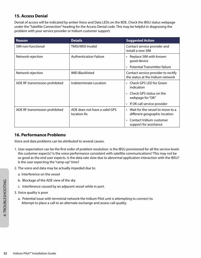
Section IV – TROUBLESHOOTING .................................................................................................................... 2912. Fault Overview ..............................................................................................................................................................................2913. LED State Table .............................................................................................................................................................................2914. Troubleshooting ...........................................................................................................................................................................2915. Access Denial ................................................................................................................................................................................3216. Performance Problems ..............................................................................................................................................................32
Section V – APPENDICES .................................................................................................................................. 33Appendix A – Regulatory Approvals ...........................................................................................................................................33Appendix B – Specifications ...........................................................................................................................................................36Appendix C – ADE/BDE Cable ........................................................................................................................................................39Appendix D – Installation Templates ............................................................................................................................................41Appendix E – Limited Warranties, Conditions of Use and Limitations of Liability .......................................................47Appendix F – Site Survey Tool (SST) .............................................................................................................................................55

iv Iridium Pilot™ Installation Guide
1: INTRO
DU
CTIO
N
Iridium Pilot™ Installation Guide 1
Section I – INTRODUCTION
1. Introduction Thank you for purchasing Iridium Pilot™, the NEXT generation solution for maritime broadband voice and data communications. Leveraging the world’s furthest reaching and only truly global communications network, Iridium Pilot delivers exceptional performance, reliability and durability anywhere on the planet. Powered by the Iridium OpenPort® service, and backed by an industry-leading warranty, you can count on a secure, real-time connection — wherever you happen to sail.
About This Manual
This manual is the installation guide for the Iridium Pilot platform. The readers of this manual include anyone who intends to install this system. Specific skills are required to install the Iridium Pilot platform and therefore, it is important that you observe all safety requirements listed in the beginning of this manual, and operate the system according to this guide’s guidelines.
This guide provides you with complete information on the installation and testing of the Iridium Pilot Terminal. This includes the following:
• Systeminstallation
• Systemstart-upandtest
• PC&networkconfiguration
• SystemAdministration
• Troubleshooting
Terms to Know
• ADE: AboveDecksEquipment,theradiatingunit.
• BDE: BelowDecksEquipment,theuserinterfaceunit.
• IBSU: IridiumBroadbandSubscriberUnit,TheADEandBDEtogether
• POTS: PlainOldTelephonySystem
• SIM: SubscriberIdentityModule
• PSU: PowerSupplyUnit
• Provisioned: AtermusedtoindicatetheSIMcardisactivatedforvoiceanddataconnection. This can only be done by the Service Provider.
1: IN
TRO
DU
CTI
ON
2 Iridium Pilot™ Installation Guide
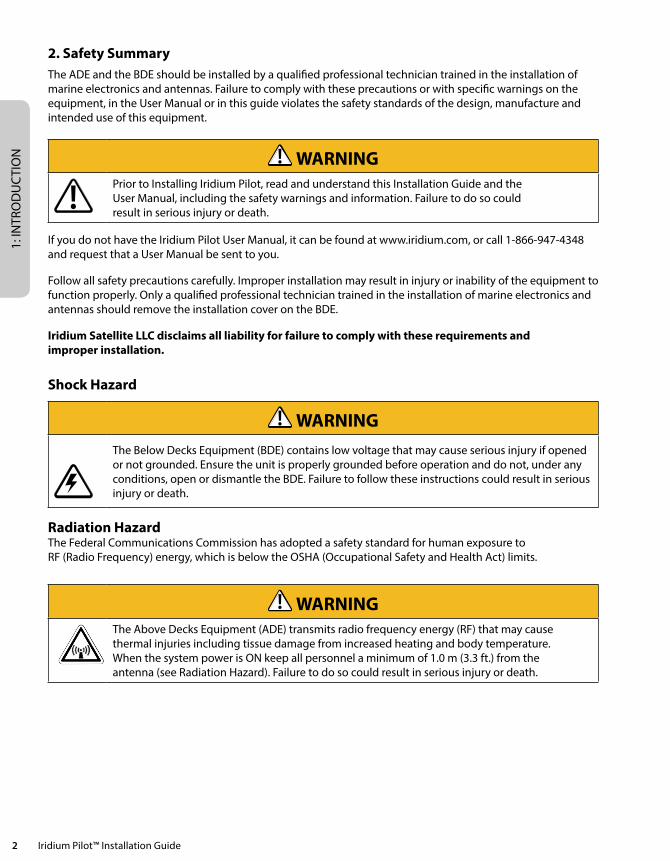
2. Safety Summary The ADE and the BDE should be installed by a qualified professional technician trained in the installation of marine electronics and antennas. Failure to comply with these precautions or with specific warnings on the equipment, in the User Manual or in this guide violates the safety standards of the design, manufacture and intended use of this equipment.
WARNINGPrior to Installing Iridium Pilot, read and understand this Installation Guide and the User Manual, including the safety warnings and information. Failure to do so could result in serious injury or death.
If you do not have the Iridium Pilot User Manual, it can be found at www.iridium.com, or call 1-866-947-4348 and request that a User Manual be sent to you.
Follow all safety precautions carefully. Improper installation may result in injury or inability of the equipment to function properly. Only a qualified professional technician trained in the installation of marine electronics and antennas should remove the installation cover on the BDE.
Iridium Satellite LLC disclaims all liability for failure to comply with these requirements and improper installation.
Shock Hazard
WARNINGThe Below Decks Equipment (BDE) contains low voltage that may cause serious injury if opened or not grounded. Ensure the unit is properly grounded before operation and do not, under any conditions, open or dismantle the BDE. Failure to follow these instructions could result in serious injury or death.
Radiation HazardThe Federal Communications Commission has adopted a safety standard for human exposure to RF (Radio Frequency) energy, which is below the OSHA (Occupational Safety and Health Act) limits.
WARNINGThe Above Decks Equipment (ADE) transmits radio frequency energy (RF) that may cause thermal injuries including tissue damage from increased heating and body temperature. When the system power is ON keep all personnel a minimum of 1.0 m (3.3 ft.) from the antenna (see Radiation Hazard). Failure to do so could result in serious injury or death.
1: INTRO
DU
CTIO
N
Iridium Pilot™ Installation Guide 3
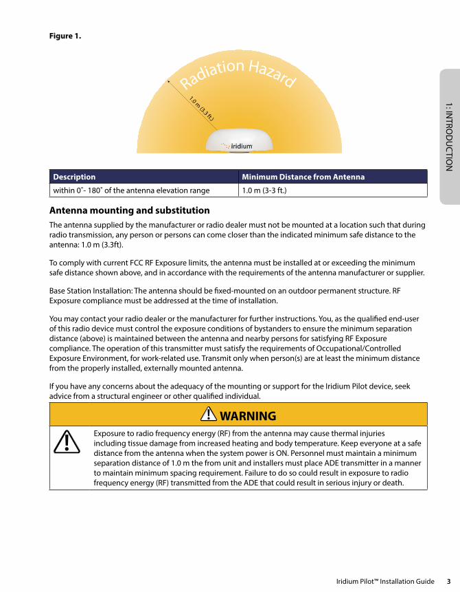
Figure 1.
Radiation Hazard1.0 m
(3.3 ft.)
Description Minimum Distance from Antenna
within 0˚- 180˚ of the antenna elevation range 1.0 m (3-3 ft.)
Antenna mounting and substitutionThe antenna supplied by the manufacturer or radio dealer must not be mounted at a location such that during radio transmission, any person or persons can come closer than the indicated minimum safe distance to the antenna: 1.0 m (3.3ft).
To comply with current FCC RF Exposure limits, the antenna must be installed at or exceeding the minimum safe distance shown above, and in accordance with the requirements of the antenna manufacturer or supplier.
Base Station Installation: The antenna should be fixed-mounted on an outdoor permanent structure. RF Exposure compliance must be addressed at the time of installation.
You may contact your radio dealer or the manufacturer for further instructions. You, as the qualified end-user of this radio device must control the exposure conditions of bystanders to ensure the minimum separation distance (above) is maintained between the antenna and nearby persons for satisfying RF Exposure compliance. The operation of this transmitter must satisfy the requirements of Occupational/Controlled Exposure Environment, for work-related use. Transmit only when person(s) are at least the minimum distance from the properly installed, externally mounted antenna.
If you have any concerns about the adequacy of the mounting or support for the Iridium Pilot device, seek advice from a structural engineer or other qualified individual.
WARNINGExposure to radio frequency energy (RF) from the antenna may cause thermal injuries including tissue damage from increased heating and body temperature. Keep everyone at a safe distance from the antenna when the system power is ON. Personnel must maintain a minimum separation distance of 1.0 m the from unit and installers must place ADE transmitter in a manner to maintain minimum spacing requirement. Failure to do so could result in exposure to radio frequency energy (RF) transmitted from the ADE that could result in serious injury or death.
1: IN
TRO
DU
CTI
ON
4 Iridium Pilot™ Installation Guide
WARNINGExposure to radio frequency energy (RF) from the antenna may cause thermal injuries including tissue damage from increased heating and body temperature. Do not substitute any antenna for the one supplied or recommended by the manufacturer or radio dealer. Substitution of antennas could cause exposure to excess radio frequency radiation which could result in serious injury or death.
WARNINGADE must be properly mounted and secured to vessel. Failure to do so could result in detachment of the unit, causing disruption in operation of the unit, or danger from a falling unit, which could result in serious injury or death.
CAUTIONDamage to the paint coating may allow rust to the ADE which could result in failure of the ADE. This in turn could cause disruption in operation of the Iridium Pilot device or danger from a falling unit. Avoid damaging the paint coating. If damage occurs, re-apply appropriate anti-corrosion paint. Failure to do so could result in serious injury or death.
Blasting Areas
WARNINGTo avoid interfering with blasting operations, turn your device OFF when in a “blasting area” or in areas posted: “Turn off two-way radio.” Obey all signs and instructions. Failure to do so could result in serious injury or death.
3. Overview of Operation Iridium’s constellation consists of 66 low-earth orbiting (LEO), cross-linked satellites operating as a fully meshed network and supported by multiple in-orbit spares. Iridium has gateways in Arizona and additional telemetry, tracking and control facilities in Canada and Norway. It is the largest commercial satellite constellation in the world.
1: INTRO
DU
CTIO
N
Iridium Pilot™ Installation Guide 5
Figure 2.
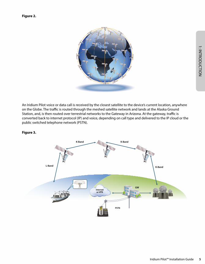
An Iridium Pilot voice or data call is received by the closest satellite to the device’s current location, anywhere on the Globe. The traffic is routed through the meshed satellite network and lands at the Alaska Ground Station, and, is then routed over terrestrial networks to the Gateway in Arizona. At the gateway, traffic is converted back to internet protocol (IP) and voice, depending on call type and delivered to the IP cloud or the public switched telephone network (PSTN).
Figure 3.
Internetor VPN
PSTN
L-Band
K-Band K-Band
K-Band
GW

1: IN
TRO
DU
CTI
ON
6 Iridium Pilot™ Installation Guide
2: INSTA
LLATION
Iridium Pilot™ Installation Guide 7
Section II – INSTALLATION
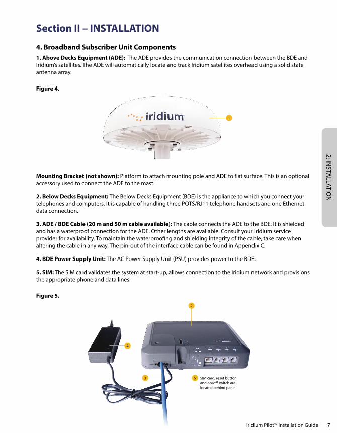
4. Broadband Subscriber Unit Components 1. Above Decks Equipment (ADE): The ADE provides the communication connection between the BDE and Iridium’s satellites. The ADE will automatically locate and track Iridium satellites overhead using a solid state antenna array.
Figure 4.
1
Mounting Bracket (not shown): Platform to attach mounting pole and ADE to flat surface. This is an optional accessory used to connect the ADE to the mast.
2. Below Decks Equipment: The Below Decks Equipment (BDE) is the appliance to which you connect your telephones and computers. It is capable of handling three POTS/RJ11 telephone handsets and one Ethernet data connection.
3. ADE / BDE Cable (20 m and 50 m cable available): The cable connects the ADE to the BDE. It is shielded and has a waterproof connection for the ADE. Other lengths are available. Consult your Iridium service provider for availability. To maintain the waterproofing and shielding integrity of the cable, take care when altering the cable in any way. The pin-out of the interface cable can be found in Appendix C.
4. BDE Power Supply Unit: The AC Power Supply Unit (PSU) provides power to the BDE.
5. SIM: The SIM card validates the system at start-up, allows connection to the Iridium network and provisions the appropriate phone and data lines.
Figure 5.
2
4
3 5 SIM card, reset buttonand on/off switch arelocated behind panel
2: IN
STA
LLAT
ION
8 Iridium Pilot™ Installation Guide
Installer/Customer Furnished Equipment
• Mounting Pole: Used to establish vertical position of ADE. Must have additional support if exposed to high winds.
• Ethernet Cable: Use if data connection is provisioned. Maximum length is 100 meters. This has to include the ADE/BDE interface cable. So the Ethernet cable length must take into account the distance between the ADE and BDE.
• Fasteners: (4) M10 (length depends on bracket, must have 15-20 mm thread engagement with ADE.
Recommended Practices/Supplies
Iridium recommends that a surge suppressor or universal power supply (UPS) unit is installed along with the Iridium Pilot product.
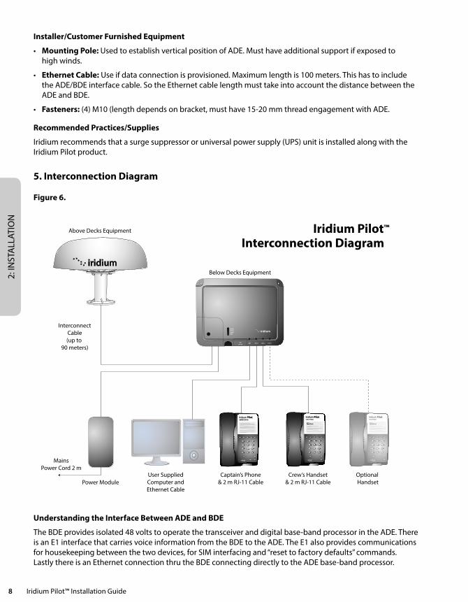
5. Interconnection Diagram
Figure 6.
Iridium Pilot™
Interconnection Diagram
InterconnectCable(up to
90 meters)
Power Module
MainsPower Cord 2 m
User SuppliedComputer andEthernet Cable
Captain’s Phone& 2 m RJ-11 Cable
Crew’s Handset& 2 m RJ-11 Cable
Optional Handset
Above Decks Equipment
Below Decks Equipment
powerstatussignal
simo� / on
data voice 1 voice 2 voice 3
GPS
1 2 3
654
7 8 9
0 #*
ABC DEF
MNOJKLGHI
PQRS TUV
MUTEVOL
REDIAL SPKR
Iridium PilotCaptain Phone
1 2 3
654
7 8 9
0 #*
ABC DEF
MNOJKLGHI
PQRS TUV
MUTEVOL
SPKR
Iridium PilotCrew Phone
Iridium
GoChat
1 2 3
654
7 8 9
0 #*
ABC DEF
MNOJKLGHI
PQRS TUV
MUTEVOL
SPKR
Iridium PilotCrew Phone
Iridium
GoChat
Understanding the Interface Between ADE and BDE
The BDE provides isolated 48 volts to operate the transceiver and digital base-band processor in the ADE. There is an E1 interface that carries voice information from the BDE to the ADE. The E1 also provides communications for housekeeping between the two devices, for SIM interfacing and “reset to factory defaults” commands. Lastly there is an Ethernet connection thru the BDE connecting directly to the ADE base-band processor.
2: INSTA
LLATION
Iridium Pilot™ Installation Guide 9
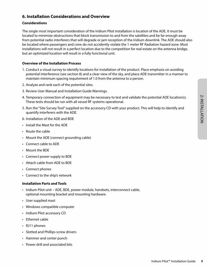
6. Installation Considerations and Overview Considerations
The single most important consideration of the Iridium Pilot installation is location of the ADE. It must be located to minimize obstructions that block transmission to and from the satellites and be far enough away from potential radio interferers that will degrade or jam reception of the Iridium downlink. The ADE should also be located where passengers and crew do not accidently violate the 1 meter RF Radiation hazard zone. Most installations will not result in a perfect location due to the competition for real estate on the antenna bridge, but an optimized location will result in a fully functional unit.
Overview of the Installation Process
1. Conduct a visual survey to identify locations for installation of the product. Place emphasis on avoiding potential interference (see section 8) and a clear view of the sky, and place ADE transmitter in a manner to maintain minimum spacing requirement of 1.0 from the antenna to a person.
2. Analyze and rank each of the potential sites.
3. Review User Manual and Installation Guide Warnings.
4. Temporary connection of equipment may be necessary to test and validate the potential ADE location(s). These tests should be run with all vessel RF systems operational.
5. Run the “Site Survey Tool” supplied on the accessory CD with your product. This will help to identify and quantify interferers with the ADE.
6. Installation of the ADE and BDE
• InstalltheMastfortheADE
• Routethecable
• MounttheADE(connectgroundingcable)
• ConnectcabletoADE
• MounttheBDE
• ConnectpowersupplytoBDE
• AttachcablefromADEtoBDE
• Connectphones
• Connecttotheship’snetwork
Installation Parts and Tools
• IridiumPilotunit–ADE,BDE,powermodule,handsets,interconnectcable, optional mounting bracket and mounting hardware.
• Usersuppliedmast
• Windowscompatiblecomputer
• IridiumPilotaccessoryCD
• Ethernetcable
• RJ11phones
• SlottedandPhillipsscrewdrivers
• Hammerandcenterpunch
• Powerdrillandassociatedbits
2: IN
STA
LLAT
ION
10 Iridium Pilot™ Installation Guide
• Wirecutters
• Wirestrippersandterminallugcrimper
• RJ-45Crimptool
• Electricaltape
6.1 Choosing a Location for the ADE
Proper location is critical to ensure proper communications between the Iridium Broadband Subscriber Unit (IBSU) and the Iridium satellite network.
WARNING
The Above Decks Equipment (ADE) transmits radio frequency (RF) that may cause thermal injuries including tissue damage from increased heating and body temperature. When the system power is ON keep all personnel a minimum of 1.0 m (3.3 ft.) from the antenna (see Radiation Hazard). Failure to do so could result in serious injury or death.
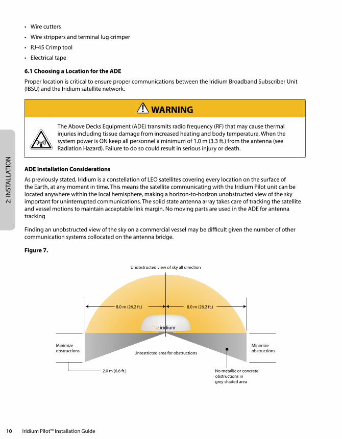
ADE Installation Considerations
As previously stated, Iridium is a constellation of LEO satellites covering every location on the surface of the Earth, at any moment in time. This means the satellite communicating with the Iridium Pilot unit can be located anywhere within the local hemisphere, making a horizon-to-horizon unobstructed view of the sky important for uninterrupted communications. The solid state antenna array takes care of tracking the satellite and vessel motions to maintain acceptable link margin. No moving parts are used in the ADE for antenna tracking
Finding an unobstructed view of the sky on a commercial vessel may be difficult given the number of other communication systems collocated on the antenna bridge.
Figure 7.
Unobstructed view of sky all direction
Unrestricted area for obstructions
8.0 m (26.2 ft.)
2.0 m (6.6 ft.)
8.0 m (26.2 ft.)
No metallic or concrete obstructions in grey shaded area
Minimizeobstructions
Minimizeobstructions

2: INSTA
LLATION
Iridium Pilot™ Installation Guide 11
Elevation Probability
The below graph shows the importance of low elevation visibility of the sky, where 90% of the time a spacecraft will be less than 45° above the local horizon.
Obstructions Around the ADE
To ensure the best possible connection with the Iridium satellite network the ADE needs clear exposure, in all directions, to the sky. Two types of obstructions that should be considered when deciding the placement of the ADE include: metallic and superstructure obstructions.
The loss of signal (dB) will increase the closer the obstruction is to the ADE. The table below shows the correlation between the size of the obstruction and the distance of the obstruction from the ADE and the amount of signal loss.
Obstruction Signal Loss Table – Signal interference around the ADE
Diameter of Obstruction Obstruction Distance Signal Loss
.2 m (.7 ft.) < 2 m (6.5 ft.) 2 dB
< 4 m (13.1 ft.) 1 dB
.4 m (1.3 ft.) < 9 m (29.5 ft.) 2 dB
< 31 m (101.8 ft.) 1 dB
.6 m (2 ft.) < 22 m (72.2 ft.) 2 dB
< 75 m (246 ft.) 1 dB
.8 m (2.6 ft.) < 40 m (131.2 ft.) 2 db
1 dB
1.0 m (3.3 ft.) < 65 m (213.2 ft.) 2 dB
1 dB
The ship’s RADAR and high power transmitters may cause signal interference.
To avoid possible damage to the ADE and degradation of ADE performance the unit must be mounted as far away as practical from these units. In addition it should also be kept clear of other sources of interference such as other Iridium or Inmarsat terminals.
The diagrams and tables below are only guidelines as the minimum distances will be dependent on the exact transmitter characteristics as well as reflections from masts, decks and other items in the vicinity of the ADE. The tables for X and S-band radar distances are minimum distances to avoid damage to the ADE and do not necessarily guarantee a good communication link.
Minimum Distance from S-band & X-band RADARs
S-band (- 10 cm / 3 GHz) radars
Radar Power Min distance at 15˚ vertical separation Min distance at 60˚ vertical separation
0 – 10kW 0.4 m (1.3 ft.) 0.4 m (1.3 ft.)
30kW 1.0 m (3.3 ft.) 0.5 m (1.6 ft.)
50kW 2.0 m (6.6 ft.) 1.0 m (3.3 ft.)
2: IN
STA
LLAT
ION
12 Iridium Pilot™ Installation Guide
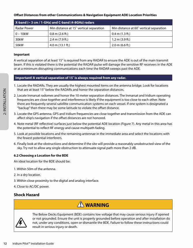
Offset Distances from other Communications & Navigation Equipment ADE Location Priorities
X-band (~ 3 cm / 1-GHz) and C-band (4-8GHz) radars
Radar Power Min distance at 15˚ vertical separation Min distance at 60˚ vertical separation
0 – 10kW 0.8 m (2.6 ft.) 0.4 m (1.3 ft.)
30kW 2.4 m (7.9 ft.) 1.2 m (3.9 ft.)
50kW 4.0 m (13.1 ft.) 2.0 m (6.6 ft.)
Important
A vertical separation of at least 15° is required from any RADAR to ensure the ADE is out of the main transmit beam. If this is violated there is the potential the RADAR pulse will damage the sensitive RF receivers in the ADE or at a minimum disrupting communications each time the RADAR sweeps past the ADE.
Important! A vertical separation of 15˚ is always required from any radar.
1. Locate the RADARs. They are usually the highest mounted items on the antenna bridge. Look for locations that are at least 15° below the RADARs and honor the separation distances.
2. Locate Inmarsat radomes and honor the 10 meter separation distances. The Inmarsat and Iridium operating frequencies are close together and interference is likely if the equipment is too close to each other. Note there are frequently several satellite communication systems on each vessel. If one system is designated a “backup” then there may be some latitude to violate the offset distance.
3. Locate the GPS antenna. GPS and Iridium frequencies are close together and transmission from the ADE can affect ship’s navigation if the offset distances are not honored.
4. Note metal (RF reflective) surfaces just below the potential ADE location (Figure 7). Any metal in this area has the potential to reflect RF energy and cause multipath fading.
5. Look at possible locations and the remaining antennae in the immediate area and select the locations with the fewest potential interferers.
6. Finally look at the obstructions and determine if the site will provide a reasonably unobstructed view of the sky. Try not to allow any single obstruction to attenuate signal path more than 2 dB.
6.2 Choosing a Location for the BDE
An ideal location for the BDE should be:
1. Within 50m of the antenna.
2. In a dry location.
3. Within close proximity to the digital and analog interface.
4. Close to AC/DC power.
Shock Hazard
WARNING
The Below Decks Equipment (BDE) contains low voltage that may cause serious injury if opened or not grounded. Ensure the unit is properly grounded before operation and after installation do not, under any conditions, open or dismantle the BDE. Failure to follow these instructions could result in serious injury or death.
2: INSTA
LLATION
Iridium Pilot™ Installation Guide 13
7. How to Connect the System1. Connect the 9-pin circular connector on the interface cable to the ADE receptacle on the bottom of the
ADE. Note you can use the ADE shipping container as a temporary platform to support the ADE and provide clearance for the connector and cable by cutting a small hole on the cardboard box. Elevate the ADE to the approximate intended install height and use a temporary platform to hold the unit. Orient the grounding lug on the bottom of the ADE aft towards the stern of the vessel.
2. Route the interface cable along the deck to a location where Mains power is available. Tape the cable to the deck to reduce any trip hazard during the temporary operation of the system.
3. Remove the “installation cover” on the BDE and Connect the interface cable (RJ-45) and the green connector from the power module. You can leave the cover off at this time.
4. Remove the SIM cover and install the SIM noting the correct orientation as indicated on the unit. Close the SIM latch and make sure the power switch is in the off position. Leave the SIM cover off during the test.
5. Connect the mains cable to the power module and connect the other end to the Ship’s mains power outlet. The LED on the power module should light and the Power LED on the BDE should light.
6. Connect a cable from the BDE “Data” port to the RJ-45 connector on the lap top computer.
7. Connect the RJ-11 cable from “Voice 1” on the BDE to the “Normal” handset.
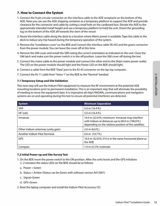
7.1 Temporary Setup and Site Validation
This next step will use the Iridium Pilot equipment to measure the RF environment at the potential ADE mounting locations prior to permanent installation. This is an important step that will eliminate the possibility of needing to move the equipment later. It is imperative all ship’s RADARs, communications and navigation systems are on and operating during this test to ensure all potential interferers are detected.
System Minimum Separation
VHF 5.0 m (16.4 ft.)
HF (ssb) 5.0 m (16.4 ft.)
Inmarsat 10.0 m (32.8 ft.) minimum. Inmarsat may interfere with Iridium at distances up to 60.0 m (196.8 ft.) depending on the relative position of the satellites.
Other Iridium antennas (unity gain) 2.0 m (6.6 ft.)
Another Iridium Pilot Terminal 6.0 m (19.7 ft.)
GPS 10.0 m (32.8 ft.) if it is in the same horizontal plane as the ADE
Compass 1.0 m (3.3 ft.) estimate
7.2 Initial Power-up and Site Survey Test
1. On the BDE move the power switch to the ON position. After the units boots and the GPS initializes (< 2 minutes) the status LEDs on the BDE should be as follows:
a. Power = Green
b. Status = Amber (Status can be Green with software version A012001)
c. Signal=Green
d. GPS=Green
2. Boot the laptop computer and install the Iridium Pilot Accessory CD.
2: IN
STA
LLAT
ION
14 Iridium Pilot™ Installation Guide
3. The PC should display the CD directory. Select the Site Survey Tool (SST) and double click to start the tool. (note the tool assumes the default IP address if the address has been changed select the settings menu from the Task bar and input the alternate IP address).
4. At this time make sure the ship’s navigation and communication systems are on and active.
5. Click on the “Start” button on the SST application to begin the test. The tool scans ~ 2.6 channels per second requiring 97 seconds to complete a single scan. Several scans are useful in assessing the local noise environment and to detect down link information from the Iridium constellation. Note the screen will be updating to provide feedback the program is executing normally.
6. This test validates that you have placed the Iridium equipment in a good location. See Appendix G for more information on the SST.
8. Installing the System Now that a suitable location for the ADE has been verified the equipment can be permanently installed for operation. The permanent installation is comprised of 4 steps.
1. Route the ADE/BDE interface cable.
2. Connect and mount the ADE.
3. Mount the BDE and make the connections to ADE, telephones and computer network.
4. Test and verify the installation.
Routing the ADE/BDE Interface Cable
The interface cable has a waterproof circular connector that connects to the ADE and a shielded RJ-45 connector that connects to the BDE. Since the BDE side is much smaller it makes sense to pull the cable from the ADE towards the BDE. Once the ADE site is known a BDE location must be selected that is within 100 meters, accounting for the path thru the cable chase. Drill the necessary hole to route the cable to the interior of the vessel. The cable should be pulled with the RJ-45 connector installed since it has been tested in previous steps. Use care and install a pull string that attaches to the cable jacket and does not place stress on the connector. Use electrical tape to protect the RJ-45 during the pull operation. Leave just enough service loop at the ADE and store any excess cable in the cable chase or near the BDE.
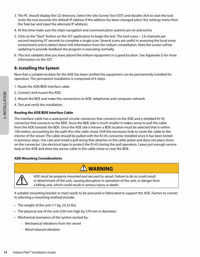
ADE Mounting Considerations
WARNINGADE must be properly mounted and secured to vessel. Failure to do so could result in detachment of the unit, causing disruption in operation of the unit, or danger from a falling unit, which could result in serious injury or death.
A suitable mounting bracket or mast needs to be procured or fabricated to support the ADE. Factors to consier in selecting a mounting method include:
• Theweightoftheunit(11kg,24.25lbs)
• Thephysicalsizeoftheunit(230mmhighby570mmindiameter)
• Mechanicalresonanceofthesystemexcitedby:
- Mechanical vibrations from the vessel
- Wind induced vibration
2: INSTA
LLATION
Iridium Pilot™ Installation Guide 15
These factors will be discussed in the following paragraphs. The mounting bracket and pole must be capable of supporting the weight of the unit. Consideration should also be given to accessibility for installation and service work, and the task of lifting and supporting the size and weight of the equipment safely whilst all the connections are being made. The mounting bracket and pole must be capable of supporting the lateral loads caused by the wind. For example at 60 mph the lateral force on the ADE alone (ie. excluding the pole) will be approximately 3.5-4.5 kgf. This load will generate shearing and bending forces in the mounting bracket and pole which must be distributed safely into the vessel’s structure. Since this loading will vary continuously with time, the structure must not only withstand the static loading but also the fatigue loading over the lifetime of installation.
When selecting a suitable mounting pole it is important to consider resonance as well as strength. The ADE will be subject to vibrations caused by oscillating aerodynamic forces due to vortex shedding from the ADE itself (in the range 0 – 10 Hz for wind speeds up to 60 mph, or storm force 10), and any upstream objects even if they are outside the zone shown in figure 7.
The ADE will also be subject to vibrations transmitted through the vessel’s structure (from engines, propellers, motorized equipment, cable stays or guy ropes). Careful consideration must therefore be given to minimize the potential for vibration causing damage to the ADE, by careful choice of the mounting position, pole diameter, pole length, and any necessary supporting structure. If necessary modify the design of the mounting pole to move its natural frequency (with ADE fitted) away from the frequency of the source of vibration. For example, increasing the stiffness of the mounting pole will increase its natural frequency – this might be achieved by using a shorter or thicker pole, but note that adding mass will have the contrary effect of reducing the natural frequency. If the pole cannot be shortened, then consider adding rigid support struts or tensioned guy ropes to reduce the effective length. The following guidelines are recommended:
• Minimumpolediameter:D=60.3mm(2.38in.)
• Minimumwallthickness:t=3.2mm(.125in.)
• Maximumunsupportedpolelength,L=2.0m(6.6ft)
For 100 mph winds (hurricane force 12) the unsupported length should be reduced to 1.0 m (3.3 ft.). Longer poles are possible if additional support is provided such as guy ropes. More sophisticated mounting designs may be necessary to deal with vibrations in some installations. The design of vibration reducing or absorbent mountings is critically dependent on many installation specific factors that are well outside the scope of this manual. Hence for any such an installation, consult specialist suppliers of marine antenna mountings, to obtain professional advice.
2: IN
STA
LLAT
ION
16 Iridium Pilot™ Installation Guide
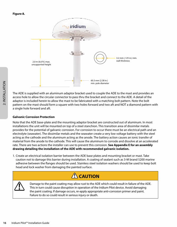
Figure 8.
2.0 m (6.6 ft.) max.unsupported height
3.2 mm (.125 in.) min.wall thickness
60.3 mm (2.38 in.)min. pole diameter
The ADE is supplied with an aluminum adaptor bracket used to couple the ADE to the mast and provides an access hole to allow the circular connector to pass thru the bracket and connect to the ADE. A detail of the adaptor is included herein to allow the mast to be fabricated with a matching bolt pattern. Note the bolt pattern on the mast should form a square with two holes forward and two aft and NOT a diamond pattern with a single hole forward and aft.
Galvanic Corrosion Protection
Note that the ADE base-plate and the mounting adaptor bracket are constructed out of aluminum. In most installations the unit will be mounted on top of a steel stanchion. This transition area of dissimilar metals provides for the potential of galvanic corrosion. For corrosion to occur there must be an electrical path and an electrolyte (seawater). The dissimilar metals and the seawater create a very low voltage battery with the steel acting as the cathode and the aluminum acting as the anode. The battery action causes an ionic transfer of material from the anode to the cathode. This will cause the aluminum to corrode and dissolve at an accelerated rate. There are two actions the installer can use to prevent this corrosion. See Appendix E for an assembly drawing detailing the installation of the ADE with recommended galvanic isolation.
1. Create an electrical isolation barrier between the ADE base plates and mounting bracket or mast. Take caution not to damage this barrier during installation. A coating of sealant such as 3-M brand 5200 marine adhesive between the flanges should be used. Stainless steel isolation washers should be used to keep bolt head and lock washer from damaging the painted surface.
CAUTIONDamage to the paint coating may allow rust to the ADE which could result in failure of the ADE. This in turn could cause disruption in operation of the Iridium Pilot device. Avoid damaging the paint coating. If damage occurs, re-apply appropriate anti-corrosion primer and paint. Failure to do so could result in serious injury or death.
2: INSTA
LLATION
Iridium Pilot™ Installation Guide 17
2. Provide a water barrier to prevent the seawater (electrolyte) from reaching the area between the dissimilar metals. Again 3-M brand 5200 adhesive, or equivalent, can be used for this purpose to cover all the fasteners and areas between the flanges.
These two steps should significantly reduce the possibility galvanic corrosion and structural failure of the adaptor mounting bracket.
ADE Mounting
There is more than one approach that can be taken to install the ADE. The installation of the ADE is dependent on the vessel structure. Follow these generic steps to install the ADE:
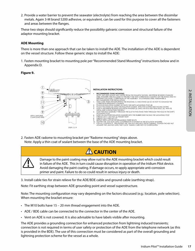
1. Fasten mounting bracket to mounting pole per “Recommended Stand Mounting” instructions below and in Appendix D.
Figure 9.
STEPS 12-19
3
5
1
9APPLY ANTI-SEIZE COMPOUND HERE
11
10
9
9
INSTALLATION INSTRUCTIONS:
RECOMMENDED STAND MOUNTING•NOTE: SHIP-SIDE MOUNT MAY DIFFER FROM THE EXAMPLE SHOWN. NEOPRENE BONDED STAINLESS STEEL WASHERS ARE INCLUDED TO PROTECT THE ANTI-CORROSION COATING ON THE STAND AND TO PREVEND GALVANIC CORROSION OF THE ASSEMBLY. 316 STAINLESS STEEL HARDWARE IS RECOMMENDED FOR INSTALLATION.TAKE CARE WHEN TRANSPORTING THE RADOME (1) AND STAND (2) SO AS NOT TO DAMAGE THE 1.CORROSION RESISTANT COATINGSPLACE AN ISOLATION GASKET (3) ONTO THE SHIP'S MOUNTING POST (8)2.PLACE THE STAND (2) ONTO THE ISOLATION GASKET, WITH THE SLOTTED SIDE FACING DOWN3.SLIDE A NEOPRENE BONDED ISOLATION WASHER (5) ONTO AN M10 HEX HEAD BOLT (4), WITH ITS 4.METAL SIDE CONTACTING THE BOLTSLIDE THIS BOLT ASSEMBLY THROUGH THE SLOT IN THE STAND THEN THROUGH THE HOLE IN THE SHIP'S 5.MOUNTING POSTSLIDE ON ANOTHER ISOLATION WASHER WITH THE RUBBER SIDE FACING THE MOUNTING POST6.THREAD ON A JAM NUT (6) FINGER TIGHT7.THREAD ON A HEX NUT (7)8.REPEAT STEPS 4-8 FOR THE REMAINING THREE BOLTS9.TIGHTEN THE JAM NUTS UNTIL COMPRESSION IS EVIDENT IN THE ISOLATION WASHERS10.FOR ALL FOUR BOLTS: PREVENTING THE JAM NUT AND BOLT FROM TURNING, TIGHTEN THE HEX NUT 11.AGAINST THE JAM NUT UNTIL THEY LOCK, TAKING CARE NOT TO OVERTIGHTEN
RADOME MOUNTING•NOTE: GROUNDING LUG ON RADOME BASE MUST BE FACING STERN. ALIGN SHIP-SIDE MOUNT ACCORDING TO THE DIAGRAM BELOW THESE INSTRUCTIONSPLACE AN ISOLATION GASKET (3) ON TOP OF THE STAND12.ROUTE THE POWER/DATA CABLE (NOT PICTURED) THROUGH EITHER THE BOTTOM OF THE STAND OR 13.THROUGH ITS SIDE HOLE, UP THROUGH THE TOP HOLE IN THE STAND. PLUG THE CABLE INTO THE CONNECTOR ON THE BOTTOM OF THE RADOMEPLACE THE RADOME ONTO THE STAND, WITH THE ARROW ON THE BASE POINTING TOWARD THE BOW14.SLIDE A LOCK WASHER (9) THEN AN ISOLATION WASHER (5) ONTO AN M10x30mm HEX HEAD BOLT 15.(10). THE METAL SIDE OF THE ISOLATION WASHER SHOULD FACE THE LOCK WASHER. APPLY ANTI-SEIZE COMPOUND (12, NOT PICTURED) TO THE BOLT THREADSSLIDE THE PREPARED BOLT UP THROUGH THE STAND, AND FINGER TIGHTEN INTO THE DOME ARRAY16.REPEAT STEPS 12 AND 14 FOR THE REMAINING THREE BOLTS17.TORQUE THE FOUR BOLTS UNTIL COMPRESSION IS EVIDENT IN THE ISOLATION WASHER18.ATTACH GROUND CABLE BETWEEN TWO LOCK WASHERS (9) ON THE 20mm M10 BOLT (11) AND 19.TIGHTEN INTO GROUND POST
STARBOARDPORT
STERN
BOWBOW
STERN
PORT STARBOARD
CORRECT SHIP-SIDE MOUNT ORIENTATION: INCORRECT SHIP-SIDE MOUNT ORIENTATIONDO NOT USE
REVISIONS
REV. DESCRIPTION DATE
PA1 INITIAL CONTROLLED DRAWING 4/27/2011
PA2 DIFFERENT HARDWARE CHOICE, NEW INSTALLATIOIN INSTRUCTIONS 5/9/2011
PA3 HARDWARE CHANGE, ANTI-SEIZE COMPOUND ADDED, INSTALLATION INSTRUCTIONS UPDATED 5/19/2011
PA4
ADDED GROUND BOLT, REPLACED BUTTON HEAD SCREW WITH LONGER HEX HEAD, CHANGED PART
DESCRIPTIONS, ADDED SHIP-SIIDE MOUNT ORIENATATION
5/20/2011
PA5 LOCK WASHERS ADDED TO GROUND BOLT, ASSEMBLY INSTRUCTIONS UPDATES 5/23/2011
PA6 ISOLATION GASKET ADDED BETWEEN HST100 AND ODU STAND, INSTRUCTION SUPDATED 10/28/2011
ITEM NO. PART NUMBER DESCRIPTION QTY.1 HST100 RADOME ASSEMBLY 12 ODU-STAND ODU STAND 13 GSK113 RUBBER ISOLATION GASKET 24 INSTALLER PROVIDED M10 316 S/S HEX BOLT 45 94709A418 MCMASTER RUBBER+ STEEL WASHER 3/8 126 INSTALLER PROVIDED M10 JAM NUT 316 S/S 47 INSTALLER PROVIDED M10 HEX NUM 316 S/S 48 SHIP-SIDE MOUNT TYPICAL SHIP-SIDE MOUNT 09 93925A290 MCMASTER LOCK WASHER M10 6
10 93635A424 MCMASTER M10-1.5X30 MACHINE SCREW 411 93635A416 MCMASTER M10X20MM HEX BOLT 316 SS 112 ANTI-SEIZE COMPOUND LOCTITE 2.25 OZ STICK 1
6
D
C
B
A
E
F
G
H
E
A
B
C
D
F
54321 7 8 9 10 11 12
1 2 3 4 5 6 7 8
G
9 10 11
H
PA6
1:2
UNITSmm
MATERIAL
GEOMETRIC TOLERANCING PERASME Y14.5m-1994
3D REFERENCEA-ADA101_PA5
DOCUMENT NUMBERD-ADA101_PA6
DESCRIPTION
ISSUE DATE
SIZEA2
REVISION
SCALE
DRAWN BYN.MAHER
0.10 2
0.15
HOLE TO HOLEANGULAR DIMENSIONSLINEAR DIMENSIONS
TOLERANCES: UNLESS OTHERWISE SPECIFIED
THIRD ANGLE PROJECTION
THIS DRAWING AND THE INFORMATION CONTAINED HEREIN IS THE PROPERTY OF IRIDIUM SATELLITE LLC AND/OR ITS AFFILIATES AND LICENSORS, UNLESS OTHERWISE STATED. NEITHER THIS DRAWING NOR ANY SUCH INFORMATION MAY BE COPIED, REPRODUCED, TRANSMITTED, DISTRIBUTED OR OTHERWISE USED EXCEPT AS EXPRESSLY APPROVED IN WRITING BY IRIDIUM SATELLITE LLC AND/OR ITS AFFILIATES. NO RIGHTS OR LICENSES OF ANY KIND TO SUCH DRAWING OR INFORMATION (INCLUDING ANY INTELLECTUAL PROPERTY RIGHTS THEREIN) ARE TRANSFERRED TO, GRANTED TO, PROVIDED TO OR RECEIVED BY THE RECIPIENT HEREOF AS A RESULT OF THE DELIVERY HEREOF. THIS MATERIAL MAY NOT IN WHOLE OR IN PART BE COPIED, STORED ELECTRONICALLY OR COMMUNICATED TO THIRD PARTIES WITHOUT THE PRIOR WRITTEN AGREEMENT OF IRIDIUM.
SHEET1 of 1
PROPRIETARY AND CONFIDENTIAL
IRIDIUM PILOT SHIP MOUNT INSTRUCTIONS
10/31/2011
2. Fasten ADE radome to mounting bracket per “Radome mounting” steps above. Note: Apply a thin coat of sealant between the base of the ADE mounting bracket.
CAUTIONDamage to the paint coating may allow rust to the ADE mounting bracket which could result in failure of the ADE. This in turn could cause disruption in operation of the Iridium Pilot device. Avoid damaging the paint coating. If damage occurs, re-apply appropriate anti-corrosion primer and paint. Failure to do so could result in serious injury or death.
3. Install cable ties for strain relieve for the ADE/BDE cable and ground cable (earthing strap).
Note: Fit earthing strap between ADE grounding point and vessel superstructure.
Note: The mounting configuration may vary depending on the factors discussed (e.g.: location, pole selection). When mounting the bracket ensure:
• TheM10boltshave15–20mmthreadengagementintotheADE.
• ADE/BDEcablecanbeconnectedtotheconnectorinthecenteroftheADE.
• VentonADEisnotcovered.Itisalsoadvisabletohavelabelsvisibleaftermounting.
The ADE provides a grounding connection for enhanced protection from lightning induced transients; connection is not required in terms of user safety or protection of the ADE from the telephone network (as this is provided in the BDE). The use of this connection must be considered as part of the overall grounding and lightning protection scheme for the vessel as a whole.
2: IN
STA
LLAT
ION
18 Iridium Pilot™ Installation Guide
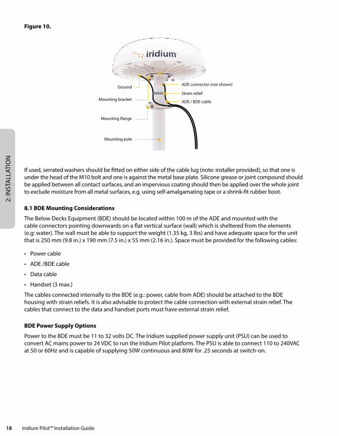
Figure 10.
Ground
Mounting bracket
Mounting �ange
ADE connector (not shown)
Strain relief
ADE / BDE cable
Mounting pole
If used, serrated washers should be fitted on either side of the cable lug (note: installer provided), so that one is under the head of the M10 bolt and one is against the metal base plate. Silicone grease or joint compound should be applied between all contact surfaces, and an impervious coating should then be applied over the whole joint to exclude moisture from all metal surfaces, e.g. using self-amalgamating tape or a shrink-fit rubber boot.
8.1 BDE Mounting Considerations
The Below Decks Equipment (BDE) should be located within 100 m of the ADE and mounted with the cable connectors pointing downwards on a flat vertical surface (wall) which is sheltered from the elements (e.g: water). The wall must be able to support the weight (1.35 kg, 3 lbs) and have adequate space for the unit that is 250 mm (9.8 in.) x 190 mm (7.5 in.) x 55 mm (2.16 in.). Space must be provided for the following cables:
• Powercable
• ADE/BDEcable
• Datacable
• Handset(3max.)
The cables connected internally to the BDE (e.g.: power, cable from ADE) should be attached to the BDE housing with strain reliefs. It is also advisable to protect the cable connection with external strain relief. The cables that connect to the data and handset ports must have external strain relief.
BDE Power Supply Options
Power to the BDE must be 11 to 32 volts DC. The Iridium supplied power supply unit (PSU) can be used to convert AC mains power to 24 VDC to run the Iridium Pilot platform. The PSU is able to connect 110 to 240VAC at 50 or 60Hz and is capable of supplying 50W continuous and 80W for .25 seconds at switch-on.
2: INSTA
LLATION
Iridium Pilot™ Installation Guide 19
If appropriate, use the provided cable when connecting the AC PSU to the AC power source. Otherwise, the installer should provide a standard IEC cable with the appropriate country plug. The 2-way connector should be connected to the “power in + and –” terminals within the installation section of the BDE.
When using DC power the installer will need to provide a suitable 2 wire + earth cable capable of providing 12/24VDC nominal (11V min, 32V max) and 50W continuous / 80W for .25 seconds at switch-on at the BDE. The positive and negative wires must be terminated using the connector from the AC PSU (provided). The 2-way connector should be connected to the “power in + and –” terminals within the installation section of the BDE. The earth should be connected to the earth tag inside the installation area.
Shock Hazard
WARNING
The Below Decks Equipment (BDE) contains low voltage that may cause serious injury if opened or not grounded. Ensure the unit is properly grounded before operation and do not, under any conditions, open or dismantle the BDE. Failure to follow these instructions could result in serious injury or death.
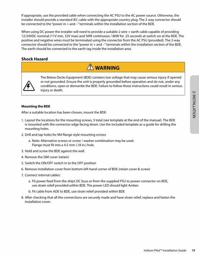
Mounting the BDE
After a suitable location has been chosen, mount the BDE:
1. Layout the locations for the mounting screws, 3 total (see template at the end of the manual). The BDE is mounted with the connector edge facing down. Use the included template as a guide for drilling the mounting holes.
2. Drill and tap holes for M4 flange style mounting screws
a. Note: Alternative screws or screw / washer combination may be used. Flange must fit into a 4.5 mm (.18 in.) hole.
3. Hold and screw the BDE against the wall.
4. Remove the SIM cover (retain)
5. Switch the ON/OFF switch in to the OFF position
6.RemoveinstallationcoverfrombottomlefthandcornerofBDE(retaincover&screw)
7. Connect internal cables:
a. Fit power feed from the ship’s DC buss or from the supplied PSU to power connector on BDE, use strain relief provided within BDE. The power LED should light Amber.
b. Fit cable from ADE to BDE, use strain relief provided within BDE
8. After checking that all the connections are securely made and have strain relief, replace and fasten the installation cover.
2: IN
STA
LLAT
ION
20 Iridium Pilot™ Installation Guide
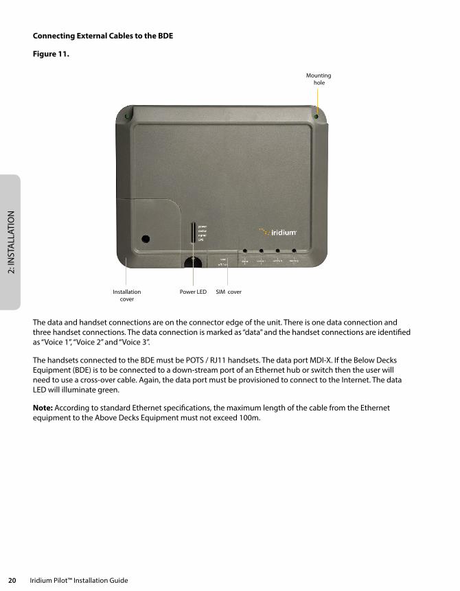
Connecting External Cables to the BDE
Figure 11.
Installationcover
Mounting hole
Power LED SIM cover
The data and handset connections are on the connector edge of the unit. There is one data connection and three handset connections. The data connection is marked as “data” and the handset connections are identified as “Voice 1”, “Voice 2” and “Voice 3”.
The handsets connected to the BDE must be POTS / RJ11 handsets. The data port MDI-X. If the Below Decks Equipment (BDE) is to be connected to a down-stream port of an Ethernet hub or switch then the user will need to use a cross-over cable. Again, the data port must be provisioned to connect to the Internet. The data LED will illuminate green.
Note: According to standard Ethernet specifications, the maximum length of the cable from the Ethernet equipment to the Above Decks Equipment must not exceed 100m.
2: INSTA
LLATION
Iridium Pilot™ Installation Guide 21
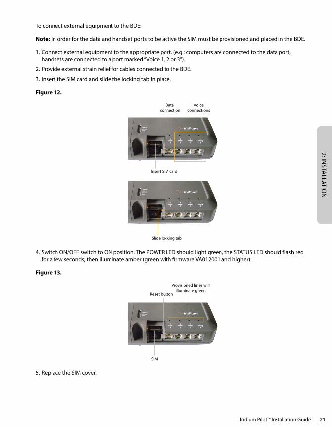
To connect external equipment to the BDE:
Note: In order for the data and handset ports to be active the SIM must be provisioned and placed in the BDE.
1. Connect external equipment to the appropriate port. (e.g.: computers are connected to the data port, handsets are connected to a port marked “Voice 1, 2 or 3”).
2. Provide external strain relief for cables connected to the BDE.
3. Insert the SIM card and slide the locking tab in place.
Figure 12.
Data connection
Insert SIM card
Slide locking tab
Reset button
Provisioned lines willilluminate green
SIM
Voiceconnections
4. Switch ON/OFF switch to ON position. The POWER LED should light green, the STATUS LED should flash red for a few seconds, then illuminate amber (green with firmware VA012001 and higher).
Figure 13.
Data connection
Insert SIM card
Slide locking tab
Reset button
Provisioned lines willilluminate green
SIM
Voiceconnections
5. Replace the SIM cover.
2: IN
STA
LLAT
ION
22 Iridium Pilot™ Installation Guide
SIM Validation
In order to access the Iridium network the BDE must have a valid SIM installed. Upon activation by the Service Provider, the customer’s SIM will be provisioned with the service level (available bandwidth) and the number of voice lines available. For example: There are three phone lines available but you choose to only provision one of them. Upon system activation only one phone line will be available.
Contact the service provider to add or remove voice phone lines. Once the service provider has added or removed voice lines, the BDE will automatically update the SIM at the next network connection.
Note: If the SIM card is removed or unlocked any voice or data calls will be terminated immediately. The SIM must be reinserted and locked into position using the locking mechanism on the SIM card holder, and then the unit must be switched off and back on again to be reactivated.
9. Install Performance TestingThis section will repeat the tests performed in sections 10 and 11 to validate the installation of the satellite equipment and links. The following steps should be followed:
1. Run the SST program again and compare the resulting graphs to the earlier “temporary installation” results. Retain both sets of results on the Ship’s computer for future trouble shooting efforts. If the results are greatly different then contact your service provider or Iridium customer support for additional help.
2. Place a voice call to the same number used in the earlier voice test. Record the subjective results and verify the voice quality is substantially the same as the previous result.
3. Run the Speed Test tool and verify the uplink and down-link speeds are within +/- 20% of the provisioned data speed.
Testing the Voice Service
Using the normal handset connected to the “Voice 1” port on the BDE place a call.
1. Ensure the SST software has been stopped.
2. Lift the receiver and listen for a dial tone.
3. Dial the country code, area code and phone number of a phone that can be used for voice quality testing. Don’t forget to press the # key to initiate the call.
4. When the call is answered verify there is intelligible voice in both directions.
5. If any issues are detected hang-up and attempt the call again. If the problem persists attempt a call to an alternate test number preferably in a different exchange (different provider) from the initial attempt.
6. If after all of these attempts there is still an issue consider the following
a. Clear voice from the Iridium Pilot unit to the landline and garbled voice in the other direction is typical of local ship interference disturbing the down-link signal.
b. If the clear voice is from the land-line side and the Iridium Pilot side is garbled then there is likely another issue and you should consult the trouble shooting section.
c. If the call is not clear in either direction then there could be an interference issue. An alternate location should be considered.
d. If the call fails to connect go to the trouble shooting section of this guide.
Note: Voice quality of the Iridium Pilot network is characterized as narrow band telephony. Significant voice compression is used in transporting voice and it can therefore sound slightly degraded from a typical mobile telephone call.
2: INSTA
LLATION
Iridium Pilot™ Installation Guide 23
Testing the Data Service
With the PC connected to the “Data” port on the BDE open a browser on the Windows computer and attempt to connect to http://speedtest.iridium.com. Once the site is visible click the “start” button. This is a customized speed test that accurately measures the performance of satellite communications. Satellite communication differs from terrestrial communications. In transitioning from stand-by to full load about 20 seconds are required to acquire the network resources. The speedtest tool has been specifically designed to account for these characteristics.
Note the speed should typically be within 20% of the provisioned rate. While checking a 128kbps link note that local activity may have the effect of slowing the link. This is not an issue at the sea since the use density is significantly reduced over that of a major port. Seldom are the lower provisioned rates affected by traffic. If a rate is out of specification wait 5 minutes and try again.
Now that the site survey, voice call, and data call have provided nominal performance you can initiate routine use of the terminal.

2: IN
STA
LLAT
ION
24 Iridium Pilot™ Installation Guide
3: NETW
ORK CO
NFIG
URATIO
N
Iridium Pilot™ Installation Guide 25
Section III – NETWORK CONFIGURATIONThe second half of this manual requires network administrative skills to complete the integration with the IT subsystem. It should only be performed if the installer has the appropriate knowledge and background.
If the Below Deck Equipment (BDE) is to be connected to a down-stream port of an Ethernet hub or switch then the user will need to use a crossover Ethernet cable. Data Service must be provisioned before you can connect to the Internet. The data LED will be illuminated green if your Iridium Pilot unit is provisioned for data.
For a Single PC • ConnectdirectlytothedataportoftheBDE
• UseastandardEthernetcable
• ConfigurePCforstaticconfiguration(formoredetailsseeUserManual)
For Multiple PCs • Connecttheswitch/hub/routertothedataportontheBDEusingacrossoverEthernetcable.
• ConnectthePCstotheEthernetswitch,huborrouter(Note:thesemultipledeviceswillbesharingthesamesatelliteconnection over the Iridium network, the more devices connected the smaller the share of the connection.)
• Dependingonhowyourship-sideLANisconfiguredyoumayormaynotwanttheIBSUtoactasaDHCPserverand to perform DNS forwarding, see the Iridium Pilot User Manual for instructions on how to change settings.
10. Initial System Configuration There are two levels of diagnostic information available, basic and administrator. Configuring the system and full diagnostics can only be done by the System Administrator and requires a login password.
Accessing the IBSU Web Pages
1. Connect a PC to the data port on the BDE
2. Open the web browser and in the web browser address window, type: http://192.168.0.1.
Note: The default IP address is assigned to the IBSU at the factory. The IP address can be changed if there are multiple IBSU’s at a single site (if this has been done then type in the new IP address). To reset the IP address back to the default (192.168.0.1), press the network reset button on the BDE.
1. Select “Login” for administrator level diagnostics. Type in the user name and password specified by Iridium (default user name and password is “admin”). Call your Service Provider if login fails.
2. Select the appropriate link:
Select to link to:
• Status
• Counters
• Diagnostic
• Configuration
• AdminPassword
3: N
ETW
ORK
CO
NFI
GU
RATI
ON
26 Iridium Pilot™ Installation Guide
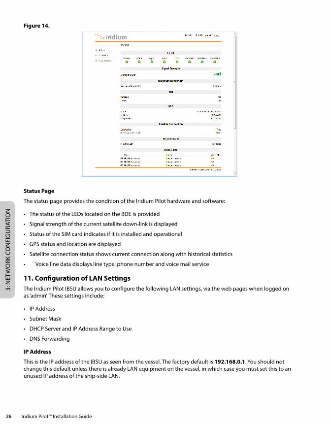
Figure 14.
Status Page
The status page provides the condition of the Iridium Pilot hardware and software:
• ThestatusoftheLEDslocatedontheBDEisprovided
• Signalstrengthofthecurrentsatellitedown-linkisdisplayed
• StatusoftheSIMcardindicatesifitisinstalledandoperational
• GPSstatusandlocationaredisplayed
• Satelliteconnectionstatusshowscurrentconnectionalongwithhistoricalstatistics
• Voicelinedatadisplayslinetype,phonenumberandvoicemailservice
11. Configuration of LAN Settings The Iridium Pilot IBSU allows you to configure the following LAN settings, via the web pages when logged on as ‘admin’. These settings include:
• IPAddress
• SubnetMask
• DHCPServerandIPAddressRangetoUse
• DNSForwarding
IP Address
This is the IP address of the IBSU as seen from the vessel. The factory default is 192.168.0.1. You should not change this default unless there is already LAN equipment on the vessel, in which case you must set this to an unused IP address of the ship-side LAN.
3: NETW
ORK CO
NFIG
URATIO
N
Iridium Pilot™ Installation Guide 27
Subnet Mask
This defines the subnet used on the vessel. The factory default is 255.255.255.0. You should only change this default if you change the IP address of the IBSU. All network devices must use the same subnet in order to communicate with one another.
Dynamic Host Configuration Protocol (DHCP) Server
This automatically provides unique IP addresses and appropriate configuration parameters to each network device connected to the IBSU. In the current configuration, DHCP is disabled.
Note: While DHCP is disabled, devices connected to the IBSU will need to have their network settings manually configured. There must only be one DHCP server on any network segment.
DHCP IP Address Minimum and Maximum
This sets the range of IP addresses for the DHCP server to use. The factory default is 192.168.0.2 to 192.168.0.254. The range specifies the maximum number of devices on the network. Both the maximum and minimum value must be in the same subnet.
Domain Name System (DNS) Forwarding
DNS is used to convert network names (such as www.iridium.com) into the IP addresses needed to connect to the device. The factory default is disabled. The IBSU acts as a switching station so that it automatically forwards DNS requests to the appropriate DNS server.
Once you change the LAN configuration and press the ‘Update IP Configuration’ button the IBSU will reboot to apply the configuration changes – this will drop any calls. Once the IBSU has rebooted any connected network devices may take up to 10 minutes to automatically obtain new settings. During this switch over time the network devices may not be able to communicate with the IBSU or/and duplicate IP address settings can occur.
If you change the LAN settings it is advisable to reboot any attached devices to avoid this issue Note: The LAN Settings can be reset to the factory defaults using the reset switch on the BDE.

3: N
ETW
ORK
CO
NFI
GU
RATI
ON
28 Iridium Pilot™ Installation Guide
4: TROU
BLESHO
OTIN
G
Iridium Pilot™ Installation Guide 29
Section IV – TROUBLESHOOTING
12. Fault Overview Problems with Iridium Pilot can be grouped together in several classifications:
1. Fundamental problems where the unit will not function locally over the Ethernet port (no diagnostic page access) or the telephone lines are non-functional.
a. Check the LED status and follow the fault tree
i. Possible power supply issue
ii. Possible ADE/BDE interface cable issue.
2. RF/Network Problem. Local communications over the Ethernet port works but connections to the internet and the PSTN are non-functional.
a. Check LED status and status and diagnostic pages and follow the fault tree
i. Possible SIM card issue
ii. Possible GPS issue
iii. Possible unit “black listed” at the gateway
iv. Possible equipment issue
3. Performance Problem. Both local and Satellite communications work but voice and/or data issues persist.
a. Possible interference or blockage issue
b. Possible equipment issue.
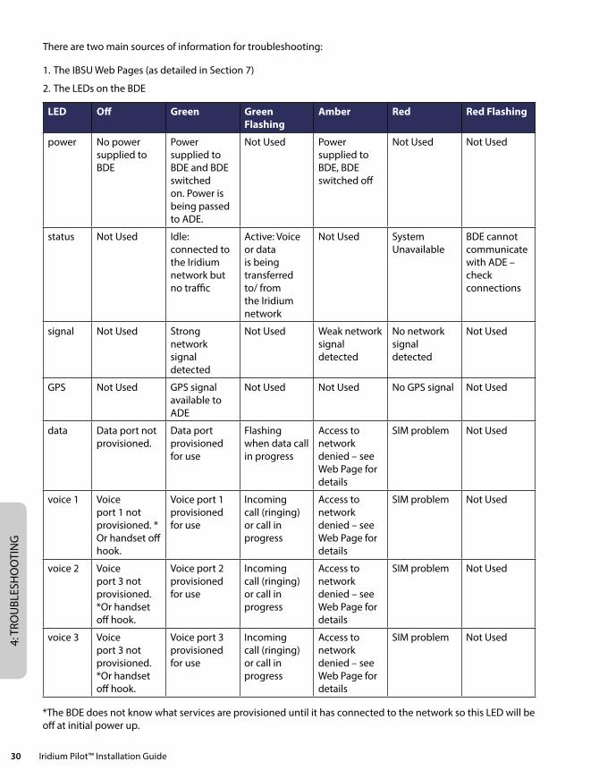
13. LED State Table • TheDataandVoiceLEDswillbeoffuntiltheunithasinitialcontactwiththeIridiumnetworktoregisterand
verify service.
• The“Status”LEDstateswerechangedinfirmwareversionAO100002andnewer.TheLEDstatetable,above,reflects this new functionality. Older versions of code should be updated to the current version to take advantage of performance improvements and enhancements.
14. Troubleshooting There are 8 LED indicators located on the BDE that can be used to initially diagnose issues with the system. Initially these indicators may be the only feedback to service personnel if the unit has a fundamental issue. During trouble shooting service personnel need to determine if the unit has previously worked and recently failed or if this is a new installation that has never worked. While troubleshooting consider changes in performance and how they may relate to other equipment that has been added to the vessel.
4: T
ROU
BLES
HO
OTI
NG
30 Iridium Pilot™ Installation Guide
There are two main sources of information for troubleshooting:
1. The IBSU Web Pages (as detailed in Section 7)
2. The LEDs on the BDE
LED Off Green Green Flashing
Amber Red Red Flashing
power No power supplied to BDE
Power supplied to BDE and BDE switched on. Power is being passed to ADE.
Not Used Power supplied to BDE, BDE switched off
Not Used Not Used
status Not Used Idle: connected to the Iridium network but no traffic
Active: Voice or data is being transferred to/ from the Iridium network
Not Used System Unavailable
BDE cannot communicate with ADE – check connections
signal Not Used Strong network signal detected
Not Used Weak network signal detected
No network signal detected
Not Used
GPS Not Used GPS signal available to ADE
Not Used Not Used No GPS signal Not Used
data Data port not provisioned.
Data port provisioned for use
Flashing when data call in progress
Access to network denied – see Web Page for details
SIM problem Not Used
voice 1 Voice port 1 not provisioned. * Or handset off hook.
Voice port 1 provisioned for use
Incoming call (ringing) or call in progress
Access to network denied – see Web Page for details
SIM problem Not Used
voice 2 Voice port 3 not provisioned. *Or handset off hook.
Voice port 2 provisioned for use
Incoming call (ringing) or call in progress
Access to network denied – see Web Page for details
SIM problem Not Used
voice 3 Voice port 3 not provisioned. *Or handset off hook.
Voice port 3 provisioned for use
Incoming call (ringing) or call in progress
Access to network denied – see Web Page for details
SIM problem Not Used
*The BDE does not know what services are provisioned until it has connected to the network so this LED will be off at initial power up.
4: TROU
BLESHO
OTIN
G
Iridium Pilot™ Installation Guide 31
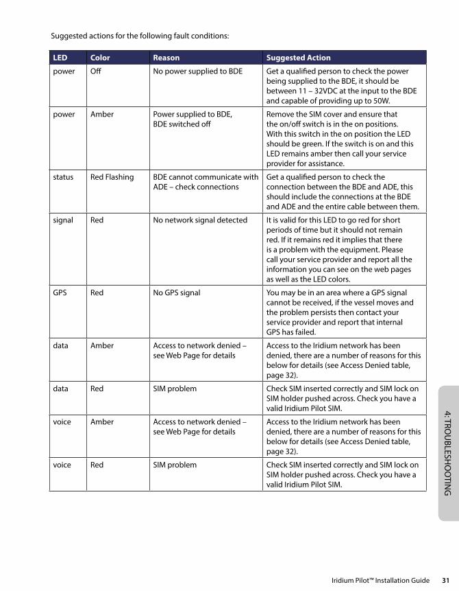
Suggested actions for the following fault conditions:
LED Color Reason Suggested Action
power Off No power supplied to BDE Get a qualified person to check the power being supplied to the BDE, it should be between 11 – 32VDC at the input to the BDE and capable of providing up to 50W.
power Amber Power supplied to BDE, BDE switched off
Remove the SIM cover and ensure that the on/off switch is in the on positions. With this switch in the on position the LED should be green. If the switch is on and this LED remains amber then call your service provider for assistance.
status Red Flashing BDE cannot communicate with ADE – check connections
Get a qualified person to check the connection between the BDE and ADE, this should include the connections at the BDE and ADE and the entire cable between them.
signal Red No network signal detected It is valid for this LED to go red for short periods of time but it should not remain red. If it remains red it implies that there is a problem with the equipment. Please call your service provider and report all the information you can see on the web pages as well as the LED colors.
GPS Red No GPS signal You may be in an area where a GPS signal cannot be received, if the vessel moves and the problem persists then contact your service provider and report that internal GPS has failed.
data Amber Access to network denied – see Web Page for details
Access to the Iridium network has been denied, there are a number of reasons for this below for details (see Access Denied table, page 32).
data Red SIM problem Check SIM inserted correctly and SIM lock on SIM holder pushed across. Check you have a valid Iridium Pilot SIM.
voice Amber Access to network denied – see Web Page for details
Access to the Iridium network has been denied, there are a number of reasons for this below for details (see Access Denied table, page 32).
voice Red SIM problem Check SIM inserted correctly and SIM lock on SIM holder pushed across. Check you have a valid Iridium Pilot SIM.
4: T
ROU
BLES
HO
OTI
NG
32 Iridium Pilot™ Installation Guide
15. Access Denial Denial of access will be indicated by amber Voice and Data LEDs on the BDE. Check the IBSU status webpage under the “Satellite Connection” heading for the Access Denial code. This may be helpful in diagnosing the problem with your service provider or Iridium customer support.
Reason Details Suggested Action
SIM non-functional TMSI/IMSI Invalid Contact service provider and install a new SIM
Network rejection Authentication Failure • ReplaceSIMwithknown good device
• PotentialTransmitterfailure
Network rejection IMEI Blacklisted Contact service provider to rectify the status at the Iridium network
ADE RF transmission prohibited Indeterminate Location • CheckGPSLEDforGreenindication
• CheckGPSstatusonthewebpage for “OK”
• IfOKcallserviceprovider
ADE RF transmission prohibited ADE does not have a valid GPS location fix
• Waitforthevesseltomovetoadifferent geographic location
• ContactIridiumcustomersupport for assistance
16. Performance Problems Voice and data problems can be attributed to several causes.
1. User expectation can be the first order of problem resolution. Is the IBSU provisioned for all the service levels the customer expects? Is the voice performance consistent with satellite communications? This may not be as good as the end user expects. Is the data rate slow due to abnormal application interaction with the IBSU? Is the user expecting the “ramp-up” time?
2. The voice and data may be actually impeded due to:
a. Interference on the vessel
b. Blockage of the ADE view of the sky
c. Interference caused by an adjacent vessel while in port.
3. Voice quality is poor
a. Potential issue with terrestrial network the Iridium Pilot unit is attempting to connect to. Attempt to place a call to an alternate exchange and assess call quality.
5: APPEN
DICES
Iridium Pilot™ Installation Guide 33
Section V – APPENDICES
Appendix A – Regulatory Approvals
FCC Declaration for 9701
This equipment has been tested and found to comply with the limits for a Class B digital device, pursuant to Part 15 of the FCC Rules. These limits are designed to provide reasonable protection against harmful interference in a residential installation.
This equipment generates uses and can radiate radio frequency energy and, if not installed and used in accordance with the instructions, may cause harmful interference to radio communications. However, there is no guarantee that interference will not occur in a particular installation.
If this equipment does cause harmful interference to radio or television reception, which can be determined by turning the equipment Off and On, the user is encouraged to try to correct the interference by one or more of the following measures:
• Reorientorrelocatethereceivingantenna.
• Increasetheseparationbetweentheequipmentandreceiver.
• Connecttheequipmentintoanoutletonacircuitdifferentfromthattowhichthereceiverisconnected.
• Consultthedealeroranexperiencedradio/TVtechnicianforhelp.
Modifications to this device not expressly approved by Iridium Satellite LLC may void authority granted under the rules of the Federal Communications Commission to operate this device.
Industry Canada
This product is compliant with Industry Canada RSS-102 for RF Exposure.
The 9701 BDE is a Class B digital apparatus and complies with Canadian ICES-003.
Cet appareil numérique de la classe B est conforme à la norme NMB-003 du Canada.
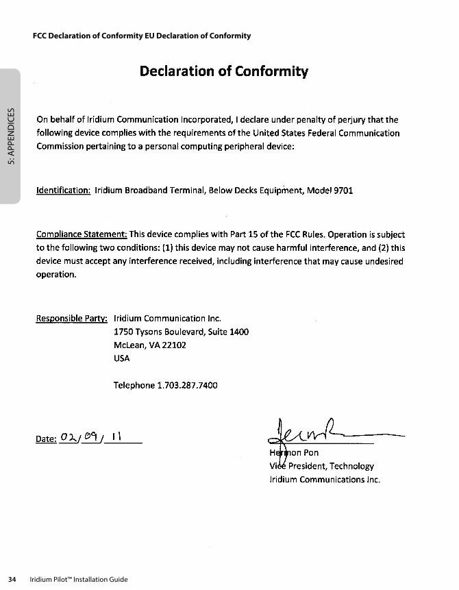
5: A
PPEN
DIC
ES
34 Iridium Pilot™ Installation Guide
FCC Declaration of Conformity EU Declaration of Conformity
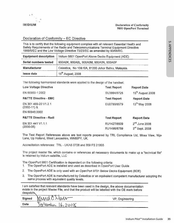
5: APPEN
DICES
Iridium Pilot™ Installation Guide 35
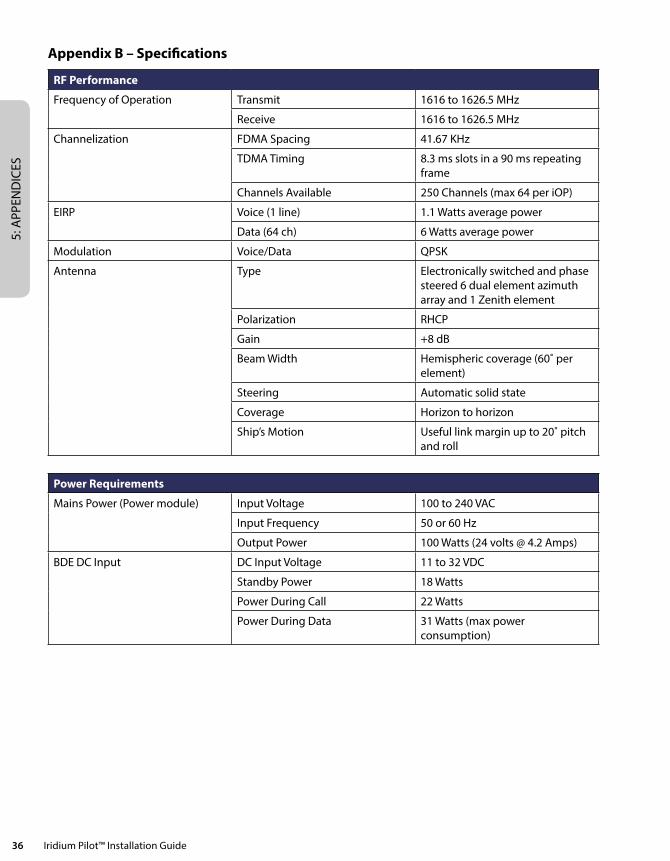
5: A
PPEN
DIC
ES
36 Iridium Pilot™ Installation Guide
Appendix B – Specifications
RF Performance
Frequency of Operation Transmit 1616 to 1626.5 MHz
Receive 1616 to 1626.5 MHz
Channelization FDMA Spacing 41.67 KHz
TDMA Timing 8.3 ms slots in a 90 ms repeating frame
Channels Available 250 Channels (max 64 per iOP)
EIRP Voice (1 line) 1.1 Watts average power
Data (64 ch) 6 Watts average power
Modulation Voice/Data QPSK
Antenna Type Electronically switched and phase steered 6 dual element azimuth array and 1 Zenith element
Polarization RHCP
Gain +8 dB
Beam Width Hemispheric coverage (60˚ per element)
Steering Automatic solid state
Coverage Horizon to horizon
Ship’s Motion Useful link margin up to 20˚ pitch and roll
Power Requirements
Mains Power (Power module) Input Voltage 100 to 240 VAC
Input Frequency 50 or 60 Hz
Output Power 100 Watts (24 volts @ 4.2 Amps)
BDE DC Input DC Input Voltage 11 to 32 VDC
Standby Power 18 Watts
Power During Call 22 Watts
Power During Data 31 Watts (max power consumption)
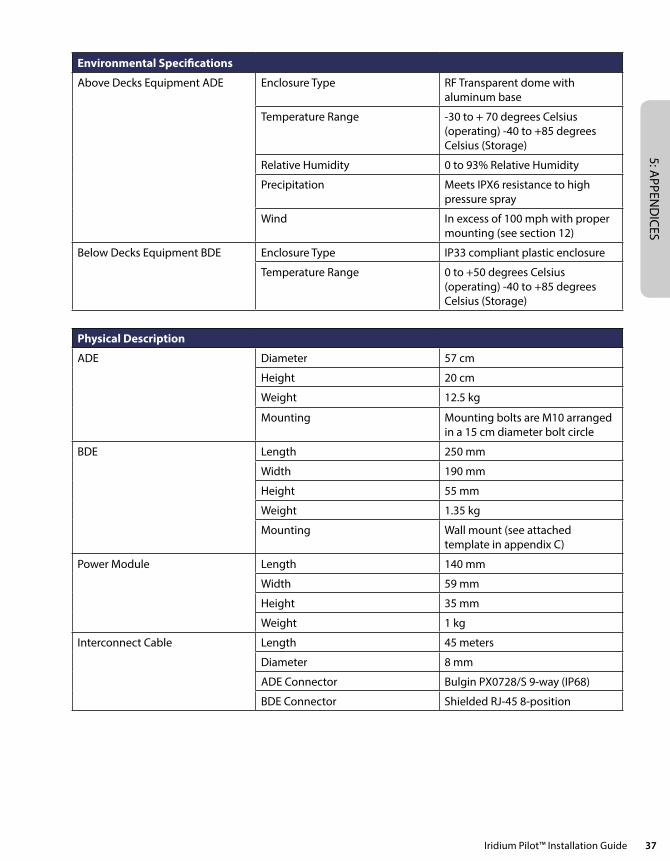
5: APPEN
DICES
Iridium Pilot™ Installation Guide 37
Environmental Specifications
Above Decks Equipment ADE Enclosure Type RF Transparent dome with aluminum base
Temperature Range -30 to + 70 degrees Celsius (operating) -40 to +85 degrees Celsius (Storage)
Relative Humidity 0 to 93% Relative Humidity
Precipitation Meets IPX6 resistance to high pressure spray
Wind In excess of 100 mph with proper mounting (see section 12)
Below Decks Equipment BDE Enclosure Type IP33 compliant plastic enclosure
Temperature Range 0 to +50 degrees Celsius (operating) -40 to +85 degrees Celsius (Storage)
Physical Description
ADE Diameter 57 cm
Height 20 cm
Weight 12.5 kg
Mounting Mounting bolts are M10 arranged in a 15 cm diameter bolt circle
BDE Length 250 mm
Width 190 mm
Height 55 mm
Weight 1.35 kg
Mounting Wall mount (see attached template in appendix C)
Power Module Length 140 mm
Width 59 mm
Height 35 mm
Weight 1 kg
Interconnect Cable Length 45 meters
Diameter 8 mm
ADE Connector Bulgin PX0728/S 9-way (IP68)
BDE Connector Shielded RJ-45 8-position
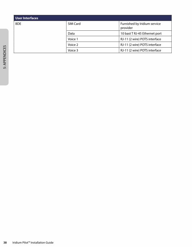
5: A
PPEN
DIC
ES
38 Iridium Pilot™ Installation Guide
User Interfaces
BDE SIM Card Furnished by Iridium service provider
Data 10 bast T RJ-45 Ethernet port
Voice 1 RJ-11 (2 wire) POTS interface
Voice 2 RJ-11 (2 wire) POTS interface
Voice 3 RJ-11 (2 wire) POTS interface
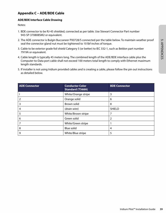
5: APPEN
DICES
Iridium Pilot™ Installation Guide 39
Appendix C – ADE/BDE Cable
ADE/BDE Interface Cable Drawing
Notes:
1. BDE connector to be RJ-45 shielded, connected as per table. Use Stewart Connector Part number 943-SP-370808SM2 or equivalent.
2. The ADE connector is Bulgin Buccaneer PX0728/S connected per the table below. To maintain weather proof seal the connector gland nut must be tightened to 10 lbf-inches of torque.
3. Cable to be exterior grade foil shield Category 5 (or better) to IEC 332-1, such as Beldon part number 7919A or equivalent.
4. Cable length is typically 45 meters long. The combined length of the ADE/BDE interface cable plus the Computer-to-Data port cable shall not exceed 100 meters total length to comply with Ethernet maximum length standards.
5. If installer is not using Iridium provided cables and is creating a cable, please follow the pin out instructions as detailed below.
ADE Connector Conductor Color Standard (T568A)
BDE Connector
I White/Orange stripe 3
2 Orange solid 6
3 Brown solid 8
4 (drain wire) SHIELD
5 White/Brown stripe 7
6 Green solid 2
7 White/Green stripe 1
8 Blue solid 4
9 White/Blue stripe 5
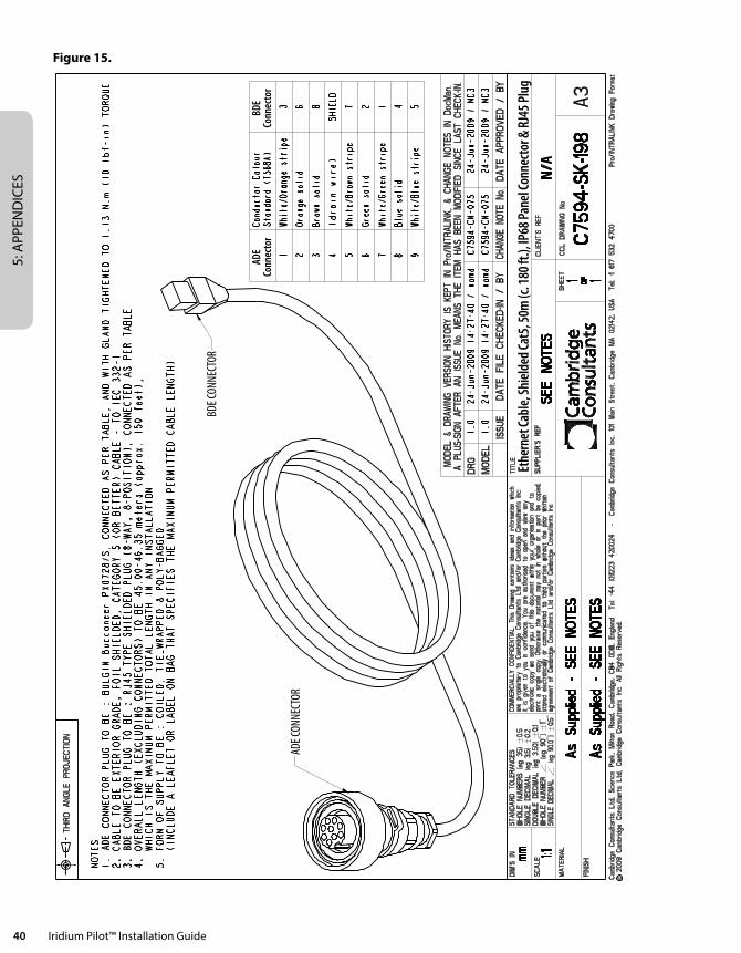
5: A
PPEN
DIC
ES
40 Iridium Pilot™ Installation Guide
Figure 15.
ADE C
ONNE
CTOR
ADE
BDE
BDE C
ONNE
CTOR
ADE
Conn
ecto
rBD
ECo
nnec
tor
Ethe
rnet
Cabl
e, Sh
ield
ed Ca
t5, 5
0m (c
. 180
ft.),
IP68
Pane
l Con
nect
or &
RJ4
5 Plu
g
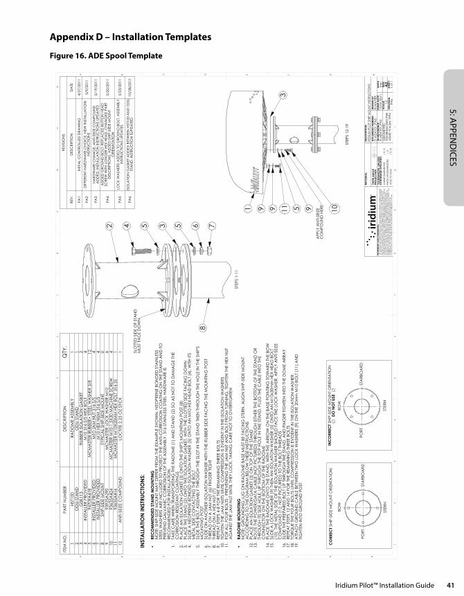
5: APPEN
DICES
Iridium Pilot™ Installation Guide 41
Appendix D – Installation Templates
Figure 16. ADE Spool Template
2 34 5 6 78
5
STEP
S 1-
11
SLO
TTED
SID
E O
F ST
AN
D
MU
ST F
AC
E D
OW
N
STEP
S 12
-19
3
51 9A
PPLY
AN
TI-S
EIZE
C
OM
POU
ND
HER
E
11 1099
INST
ALL
ATI
ON
INST
RUC
TIO
NS:
REC
OM
MEN
DED
STA
ND
MO
UN
TIN
G•
NO
TE: S
HIP
-SID
E M
OU
NT
MA
Y D
IFFE
R F
RO
M T
HE
EXA
MPL
E SH
OW
N. N
EOPR
ENE
BON
DED
STA
INLE
SS
STEE
L W
ASH
ERS
AR
E IN
CLU
DED
TO
PR
OTE
CT
THE
AN
TI-C
OR
RO
SIO
N C
OA
TIN
G O
N T
HE
STA
ND
AN
D T
O
PREV
END
GA
LVA
NIC
CO
RR
OSI
ON
OF
THE
ASS
EMBL
Y. 3
16 S
TAIN
LESS
STE
EL H
AR
DW
AR
E IS
R
ECO
MM
END
ED F
OR
INST
ALL
ATI
ON
.TA
KE C
AR
E W
HEN
TR
AN
SPO
RTI
NG
TH
E R
AD
OM
E (1
) A
ND
STA
ND
(2)
SO
AS
NO
T TO
DA
MA
GE
THE
1.C
OR
RO
SIO
N R
ESIS
TAN
T C
OA
TIN
GS
PLA
CE
AN
ISO
LATI
ON
GA
SKET
(3)
ON
TO T
HE
SHIP
'S M
OU
NTI
NG
PO
ST (
8)2.
PLA
CE
THE
STA
ND
(2)
ON
TO T
HE
ISO
LATI
ON
GA
SKET
, WIT
H T
HE
SLO
TTED
SID
E FA
CIN
G D
OW
N3.
SLID
E A
NEO
PREN
E BO
ND
ED IS
OLA
TIO
N W
ASH
ER (
5) O
NTO
AN
M10
HEX
HEA
D B
OLT
(4)
, WIT
H IT
S 4.
MET
AL
SID
E C
ON
TAC
TIN
G T
HE
BOLT
SLID
E TH
IS B
OLT
ASS
EMBL
Y TH
RO
UG
H T
HE
SLO
T IN
TH
E ST
AN
D T
HEN
TH
RO
UG
H T
HE
HO
LE IN
TH
E SH
IP'S
5.
MO
UN
TIN
G P
OST
SLID
E O
N A
NO
THER
ISO
LATI
ON
WA
SHER
WIT
H T
HE
RU
BBER
SID
E FA
CIN
G T
HE
MO
UN
TIN
G P
OST
6.TH
REA
D O
N A
JA
M N
UT
(6)
FIN
GER
TIG
HT
7.TH
REA
D O
N A
HEX
NU
T (7
)8.
REP
EAT
STEP
S 4-
8 FO
R T
HE
REM
AIN
ING
TH
REE
BO
LTS
9.TI
GH
TEN
TH
E JA
M N
UTS
UN
TIL
CO
MPR
ESSI
ON
IS E
VID
ENT
IN T
HE
ISO
LATI
ON
WA
SHER
S10
.FO
R A
LL F
OU
R B
OLT
S: P
REV
ENTI
NG
TH
E JA
M N
UT
AN
D B
OLT
FR
OM
TU
RN
ING
, TIG
HTE
N T
HE
HEX
NU
T 11
.A
GA
INST
TH
E JA
M N
UT
UN
TIL
THEY
LO
CK,
TA
KIN
G C
AR
E N
OT
TO O
VER
TIG
HTE
N
RAD
OM
E M
OU
NTI
NG
•N
OTE
: GR
OU
ND
ING
LU
G O
N R
AD
OM
E BA
SE M
UST
BE
FAC
ING
STE
RN
. ALI
GN
SH
IP-S
IDE
MO
UN
T A
CC
OR
DIN
G T
O T
HE
DIA
GR
AM
BEL
OW
TH
ESE
INST
RU
CTI
ON
SPL
AC
E A
N IS
OLA
TIO
N G
ASK
ET (
3) O
N T
OP
OF
THE
STA
ND
12.
RO
UTE
TH
E PO
WER
/DA
TA C
ABL
E (N
OT
PIC
TUR
ED)
THR
OU
GH
EIT
HER
TH
E BO
TTO
M O
F TH
E ST
AN
D O
R
13.
THR
OU
GH
ITS
SID
E H
OLE
, UP
THR
OU
GH
TH
E TO
P H
OLE
IN T
HE
STA
ND
. PLU
G T
HE
CA
BLE
INTO
TH
E C
ON
NEC
TOR
ON
TH
E BO
TTO
M O
F TH
E R
AD
OM
EPL
AC
E TH
E R
AD
OM
E O
NTO
TH
E ST
AN
D, W
ITH
TH
E A
RR
OW
ON
TH
E BA
SE P
OIN
TIN
G T
OW
AR
D T
HE
BOW
14.
SLID
E A
LO
CK
WA
SHER
(9)
TH
EN A
N IS
OLA
TIO
N W
ASH
ER (
5) O
NTO
AN
M10
x30m
m H
EX H
EAD
BO
LT
15.
(10)
. TH
E M
ETA
L SI
DE
OF
THE
ISO
LATI
ON
WA
SHER
SH
OU
LD F
AC
E TH
E LO
CK
WA
SHER
. APP
LY A
NTI
-SEI
ZE
CO
MPO
UN
D (
12, N
OT
PIC
TUR
ED)
TO T
HE
BOLT
TH
REA
DS
SLID
E TH
E PR
EPA
RED
BO
LT U
P TH
RO
UG
H T
HE
STA
ND
, AN
D F
ING
ER T
IGH
TEN
INTO
TH
E D
OM
E A
RR
AY
16.
REP
EAT
STEP
S 12
AN
D 1
4 FO
R T
HE
REM
AIN
ING
TH
REE
BO
LTS
17.
TOR
QU
E TH
E FO
UR
BO
LTS
UN
TIL
CO
MPR
ESSI
ON
IS E
VID
ENT
IN T
HE
ISO
LATI
ON
WA
SHER
18.
ATT
AC
H G
RO
UN
D C
ABL
E BE
TWEE
N T
WO
LO
CK
WA
SHER
S (9
) O
N T
HE
20m
m M
10 B
OLT
(11
) A
ND
19
.TI
GH
TEN
INTO
GR
OU
ND
PO
ST
STA
RBO
AR
DPO
RT
STER
N
BOW
BOW
STER
N
POR
TST
AR
BOA
RD
CO
RREC
T SH
IP-S
IDE
MO
UN
T O
RIE
NTA
TIO
N:
INC
ORR
ECT
SHIP
-SID
E M
OU
NT
OR
IEN
TATI
ON
DO
NO
T U
SE
REV
ISIO
NS
REV
.D
ESC
RIP
TIO
ND
ATE
PA1
INIT
IAL
CO
NTR
OLL
ED D
RA
WIN
G4/
27/2
011
PA2
DIF
FER
ENT
HA
RD
WA
RE
CH
OIC
E, N
EW IN
STA
LLA
TIO
IN
INST
RU
CTI
ON
S5/
9/20
11
PA3
HA
RD
WA
RE
CH
AN
GE,
AN
TI-S
EIZE
CO
MPO
UN
D
AD
DED
, IN
STA
LLA
TIO
N IN
STR
UC
TIO
NS
UPD
ATE
D5/
19/2
011
PA4
AD
DED
GR
OU
ND
BO
LT, R
EPLA
CED
BU
TTO
N H
EAD
SC
REW
WIT
H L
ON
GER
HEX
HEA
D, C
HA
NG
ED P
AR
T D
ESC
RIP
TIO
NS,
AD
DED
SH
IP-S
IIDE
MO
UN
T O
RIE
NA
TATI
ON
5/20
/201
1
PA5
LOC
K W
ASH
ERS
AD
DED
TO
GR
OU
ND
BO
LT, A
SSEM
BLY
INST
RU
CTI
ON
S U
PDA
TES
5/23
/201
1
PA6
ISO
LATI
ON
GA
SKET
AD
DED
BET
WEE
N H
ST10
0 A
ND
OD
U
STA
ND
, IN
STR
UC
TIO
N S
UPD
ATE
D10
/28/
2011
ITEM
NO
.PA
RT
NU
MBE
RD
ESC
RIP
TIO
NQ
TY.
1 H
ST10
0 R
AD
OM
E A
SSEM
BLY
12
OD
U-S
TAN
DO
DU
STA
ND
13
GSK
113
RU
BBER
ISO
LATI
ON
GA
SKET
24
INST
ALL
ER P
RO
VID
ED
M10
316
S/S
HEX
BO
LT4
5 9
4709
A41
8M
CM
AST
ER R
UBB
ER+
STE
EL W
ASH
ER 3
/812
6IN
STA
LLER
PR
OV
IDED
M
10 J
AM
NU
T 31
6 S/
S4
7 IN
STA
LLER
PR
OV
IDED
M10
HEX
NU
M 3
16 S
/S4
8SH
IP-S
IDE
MO
UN
TTY
PIC
AL
SHIP
-SID
E M
OU
NT
09
939
25A
290
MC
MA
STER
LO
CK
WA
SHER
M10
610
936
35A
424
MC
MA
STER
M10
-1.5
X30
MA
CH
INE
SCR
EW4
11 9
3635
A41
6M
CM
AST
ER M
10X
20M
M H
EX B
OLT
316
SS
112
AN
TI-S
EIZE
CO
MPO
UN
DLO
CTI
TE 2
.25
OZ
STIC
K1
6
DCBA E F G H
EA B C D F
54
32
17
89
1011
12
12
34
56
78
G
910
11
H
PA6
1:2
UN
ITS
mm
MA
TER
IAL
GEO
MET
RIC
TO
LER
AN
CIN
G P
ERA
SME
Y14
.5m
-199
4
3D R
EFE
RE
NC
EA
-AD
A10
1_P
A5
DO
CU
ME
NT
NU
MB
ER
D-A
DA
101_
PA
6
DE
SC
RIP
TIO
N
ISS
UE
DA
TE
SIZ
EA
2R
EV
ISIO
N
SC
ALE
DR
AW
N B
YN
.MA
HER
0.1
0 2 0.1
5
HO
LE T
O H
OLE
AN
GU
LAR
DIM
ENSI
ON
SLI
NEA
R D
IMEN
SIO
NS
TOLE
RA
NC
ES
: UN
LES
S
OTH
ER
WIS
E S
PE
CIF
IED
THIR
D A
NG
LE
PRO
JEC
TIO
NTH
IS D
RAW
ING
AN
D T
HE
INFO
RMA
TIO
N C
ON
TAIN
ED H
EREI
N IS
TH
E PR
OPE
RTY
OF
IRID
IUM
SA
TELL
ITE
LLC
AN
D/O
R IT
S A
FFIL
IATE
S A
ND
LIC
ENSO
RS, U
NLE
SS O
THER
WIS
E ST
ATE
D.
NEI
THER
TH
IS D
RAW
ING
N
OR
AN
Y SU
CH
INFO
RMA
TIO
N M
AY
BE C
OPI
ED, R
EPRO
DU
CED
, TRA
NSM
ITTE
D, D
ISTR
IBU
TED
OR
OTH
ERW
ISE
USE
D E
XCEP
T A
S EX
PRES
SLY
APP
ROV
ED IN
WRI
TIN
G B
Y IR
IDIU
M S
ATE
LLIT
E LL
C A
ND
/OR
ITS
AFF
ILIA
TES.
NO
RIG
HTS
OR
LIC
ENSE
S O
F A
NY
KIN
D T
O S
UC
H D
RAW
ING
OR
INFO
RMA
TIO
N
(INC
LUD
ING
AN
Y IN
TELL
ECTU
AL
PRO
PERT
Y RI
GH
TS T
HER
EIN
) A
RE T
RAN
SFER
RED
TO
, GRA
NTE
D T
O,
PRO
VID
ED T
O O
R RE
CEI
VED
BY
THE
REC
IPIE
NT
HER
EOF
AS
A R
ESU
LT O
F TH
E D
ELIV
ERY
HER
EOF.
TH
IS
MA
TERI
AL
MA
Y N
OT
IN W
HO
LE O
R IN
PA
RT B
E C
OPI
ED, S
TORE
D E
LEC
TRO
NIC
ALL
Y O
R C
OM
MU
NIC
ATE
D T
O T
HIR
D P
ART
IES
WIT
HO
UT
THE
PRIO
R W
RITT
EN A
GRE
EMEN
T O
F IR
IDIU
M.
SHEE
T1
of 1
PRO
PRIE
TARY
AN
D C
ON
FID
ENTI
AL
IRID
IUM
PIL
OT
SHIP
MO
UN
T IN
STR
UC
TIO
NS
10/3
1/20
11

5: A
PPEN
DIC
ES
42 Iridium Pilot™ Installation Guide
5: APPEN
DICES
Iridium Pilot™ Installation Guide 43
Figure 17. BDE Drill Template
FPO FOLD OUT
223.
3 m
m
77.6
mm
170.5 mm
TOP
BOTT
OM
BDE
Dril
l Tem
pla
te
Use
tem
pla
te to
dril
l mou
ntin
g (3
tota
l) sc
rew
hol
es.
Ensu
re te
mp
late
sca
le is
1 to
1. C
heck
all
dim
ensi
ons
bef
ore
drill
ing
to th
e w
all.

5: A
PPEN
DIC
ES
44 Iridium Pilot™ Installation Guide
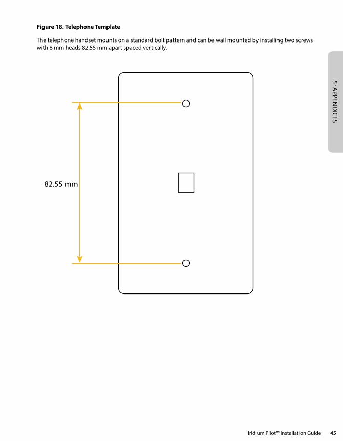
5: APPEN
DICES
Iridium Pilot™ Installation Guide 45
Figure 18. Telephone Template
The telephone handset mounts on a standard bolt pattern and can be wall mounted by installing two screws with 8 mm heads 82.55 mm apart spaced vertically.
82.55 mm

5: A
PPEN
DIC
ES
46 Iridium Pilot™ Installation Guide

5: APPEN
DICES
Iridium Pilot™ Installation Guide 47
Appendix E – Limited Warranties, Conditions of Use and Limitations of Liability
Iridium Pilot™ Products Terms and Conditions
All sales by Iridium of Iridium Pilot subscriber products (Above Deck Equipment, Below Deck Equipment, and Power Supply) (collectively the “Product”) and accessories (i.e. cables, captain and crew handsets, mounts) (“Accessories”) are subject to and conditioned upon the Purchaser’s acceptance of these Terms and Conditions. Iridium objects to any additional or different terms contained in any documentation used or submitted by buyer unless expressly accepted in writing by Iridium. If any provision of these Terms and Conditions is found invalid under applicable law or court order, all other provisions shall be unaffected and remain independently binding and valid. The provisions in these Terms and Conditions supersede any contrary provisions in other Iridium documents, including Iridium OpenPort Product Limited Warranty Policy.
1. IRIDIUM PILOT LIMITED WARRANTY
Iridium warrants only that the Product, not including Accessories, shall be free from defects in materials and workmanship for a period of sixty (60) months (five (5) years) from the date of sale to the end-user. Iridium Pilot Accessories shall be covered by this Limited Warranty for twelve (12) months (one (1) year). Iridium does not authorize any person to assume or create for it any other obligation or liability in connection with any Product or Accessories.
IRIDIUM MAKES NO OTHER WARRANTY OR GUARANTEE, EXPRESS OR IMPLIED, INCLUDING, WITHOUT LIMITA-TION, ANY WARRANTY OF MERCHANTABILITY OR FITNESS FOR A PARTICULAR PURPOSE, NON-INFRINGEMENT, SATISFACTORY QUALITY, NON-INTERFERENCE, ACCURACY OF INFORMATIONAL CONTENT, OR ARISING FROM A COURSE OF DEALING, LAW, USAGE, OR TRADE PRACTICE. IN NO EVENT SHALL IRIDIUM BE LIABLE FOR SPECIAL, INCIDENTAL, OR CONSEQUENTIAL DAMAGES ARISING OUT OF OR IN CONNECTION WITH THE PRODUCT OR ACCESSORIES, OR FOR ANY INDEMNIFICATION OF PURCHASER ON ACCOUNT OF ANY CLAIM ASSERTED AGAINST PURCHASER, OR FOR ANY OTHER DAMAGE OF ANY KIND, WHETHER DIRECTLY OR INDI-RECTLY RELATED TO THE PRODUCT, ACCESSORIES OR IRIDIUM’S SERVICE. TO THE EXTENT THAT ANY IMPLIED WARRANTY CANNOT BE DISCLAIMED, SUCH WARRANTY SHALL BE LIMITED IN DURATION TO THE EXPRESS LIMITED WARRANTY PERIOD. THIS WARRANTY IS MADE BY IRIDIUM TO THE PURCHASER OF THE PRODUCT AND ACCESSORIES ONLY, AND IT IS NOT ASSIGNABLE OR TRANSFERABLE BY THE PURCHASER. TO THE EXTENT PERMITTED BY LAW, THIS IS IRIDIUM’S SOLE AND COMPLETE WARRANTY FOR THE PRODUCT AND ACCESSO-RIES. THIS WARRANTY COVERS PRODUCT AND ACCESSORIES ONLY. IRIDIUM MAKES NO WARRANTY AS TO COVERAGE, AVAILABILITY, OR GRADE OF SERVICE PROVIDED BY IRIDIUM SEPARATELY FOR IRIDIUM SATELLITE SERVICES. IRIDIUM ASSUMES NO OBLIGATION OR LIABILITY FOR ADDITIONS OR MODIFICATIONS TO THIS WARRANTY UNLESS MADE IN WRITING AND SIGNED BY AN OFFICER OF IRIDIUM.
This Product and Accessories is covered only by the LIMITED WARRANTY as stated above. To the extent permitted by applicable law, Iridium specifically disclaims any other warranty terms, liabilities, or obligations which may be implicated by sale or purchase of the Product or Accessories outside of the United States. Except as specified in this LIMITED WARRANTY, Products and Accessories are provided “AS IS.”
If you acquired this Product and Accessories in Australia or in New Zealand, this Product and Accessories come with guarantees that cannot be excluded under the Australian Consumer Law or similar legislation in New Zealand. The benefits to a consumer given by the warranty are in addition to other rights and remedies of a consumer under a law in relation to the goods or services to which the warranty relates. Notwithstanding other express terms and other limitations of this Limited Warranty (which other express terms and other limitations are negated by this paragraph, but only to the extent inconsistent with this paragraph, and will not be applied to limit consumer rights under such guarantees), where such guarantees operate, consumers are entitled to a replacement or a refund for a major failure of this Product and Accessories and for compensation for any other reasonably foreseeable loss or damage. Where such guarantees operate, consumers are also entitled to have this Product and Accessories repaired or replaced if this Product and Accessories fail to be of acceptable
5: A
PPEN
DIC
ES
48 Iridium Pilot™ Installation Guide
quality and the failure does not amount to a major failure. Please follow the instructions as to use and report problems promptly: problems caused by use that is abnormal or contrary to instructions will generally not be covered. You should contact your Product and Accessories provider in relation to problems with the Product and Accessories and Iridium will assist your Product and Accessories provider to resolve them.
2. EXCLUSIONS
A. Product and Accessories Conditions Not Covered By The LIMITED WARRANTY in Section 1 above:
1. Product or Accessories damage caused by the use of equipment not furnished by Iridium, including accessories, power supplies and peripherals.
2. Failures caused by incompatibility of Iridium Product or Accessories used in a combination with equipment not furnished by Iridium.
3. Damage to any equipment not furnished by Iridium.
4. Defects or damage resulting from use of the Product or Accessories in any manner not in accordance with the User Manual or Installation Guide.
5. Damages resulting from accident or neglect, including but not limited to dropping the Product or Accessories on hard surfaces, submersion in water, improper testing, operation, maintenance, installation, adjustment, or any alteration or modification of any kind, including spliced or improperly terminated cables.
6. Scratches or other damage to surfaces or the appearance of externally exposed parts caused by Purchaser’s use.
B. The LIMITED WARRANTY in Section 1 of these Terms and Conditions is VOID upon the following:
1. Product integration, installation, maintenance, or service in any manner other than in accordance with the Iridium installation and user documentation furnished with or applicable to the Product or Accessories.
2. Use of ancillary equipment not furnished by Iridium which damages Iridium Product or Accessories.
3. Product or Accessories disassembly, opening, or repair performed by anyone other than an Iridium Authorized Repair Center.
4. Removal, alteration, or obliteration of serial numbers or date tags.
5. Failure to comply with these Terms and Conditions, including Limitations and Conditions of Use in Section 4 below.
3. LIMITED WARRANTY CLAIMS – PURCHASER REMEDIES
At its sole discretion, Iridium shall, at no charge to Purchaser, either repair or replace the Product or Accessories, or refund the purchase price of a Product or Accessories that does not conform to this LIMITED WARRANTY, provided that the Product or Accessories is returned in accordance with the instructions set forth below and within the LIMITED WARRANTY period set forth in Section 1 above. Repair may include the replacement of parts and/or components with functionally equivalent, reconditioned, or new parts and/or components. Product or Accessories that is repaired or replaced in accordance with these Terms and Conditions will be covered by the LIMITED WARRANTY for the balance of the original warranty period, or six (6) months, whichever is longer. A returned Product or Accessories for which a replacement has been provided shall become Iridium’s property.
To the extent permitted by applicable law, the remedies under these Terms and Conditions are Purchaser’s sole and exclusive remedies. IN NO EVENT SHALL IRIDIUM, INCLUDING ITS LICENSORS AND/OR SUPPLIERS, BE LIABLE FOR ANY AMOUNT IN EXCESS OF THE PURCHASE PRICE OF THE PRODUCT OR ACCESSORIES, OR FOR ANY LOSS OF USE, LOSS OF TIME, INCONVENIENCE, COMMERCIAL LOSS, LOST PROFITS OR SAVINGS, OR OTHER INCIDENTAL, SPECIAL, OR CONSEQUENTIAL DAMAGES ARISING OUT OF OR RELATING TO THE USE OR INABILITY TO USE SUCH PRODUCT REGARDLESS OF NOTICE OF SUCH LOSS.

5: APPEN
DICES
Iridium Pilot™ Installation Guide 49
For warranty claims, questions, repairs, service or for the return of Product or Accessories, contact the Iridium Service Provider or Point-of-Sale. Products and Accessories needing service should be returned to the Purchaser’s Service Provider or Point-of-Sale. Purchaser’s Service Provider will coordinate warranty service with Iridium to facilitate repair or replacement of the Product or Accessories. All Products and Accessories shipped to Iridium’s authorized Global Warranty Center(s) must be shipped with freight and insurance pre-paid. Products and Accessories returned to Iridium must be accompanied by a copy of the Return Material Authorization (RMA), and the RMA number referenced on the outside of the box.
Product and Accessories that are repaired or replaced under the LIMITED WARRANTY shall be returned to Purchaser at Iridium’s expense for the freight and insurance, and at Purchaser’s expense for any applicable duties or other charges. If you are a consumer entitled to return the Product under statutory guarantee, at your request Iridium will reimburse reasonable shipping costs incurred by you.
4. LIMITATIONS AND CONDITIONS OF USE
In the United States, and subject to availability, emergency calls using 911 or 112 emergency systems, are routed to emergency call centers for response. OUTSIDE OF THE UNTIED STATES, EMERGENCY ACCESS NUMBERS SUCH AS 911, 112, AND/OR 999, ARE UNAVAILABLE ON THE IRIDIUM NETWORK AND MOBILE SATELLITE SERVICE. Iridium also does not currently support enhanced 911 or 112 services and does not provide information to emergency call centers to identify callers’ locations.
Purchaser and all users of the Product and Accessories, including but not limited to the use of the Iridium phone services, in conjunction with 911, 112, or any other emergency or distress call services, both public and privately operated, acknowledge and agree as a condition of the provision of Iridium phone service that they will make no claim in contract, tort, or otherwise, against Iridium for any damages, bodily injury, loss of life, or any other loss arising from unavailability, delay, faultiness, or failures of the Iridium facilities, service, Product or Accessories, including inaccuracies with regard to any user information. Users disclaim any liability against Iridium arising from Iridium’s service in exchange for the provision of Iridium’s phone service through its Products and Accessories.
As part of providing its service, Iridium may disclose user information, including but not limited to name, address, telephone number and location information, including, where available, the geographic coordinates of equipment, to governmental and quasi-governmental agencies where Iridium deems it necessary in its sole discretion to respond to exigent circumstances or as required by law. Governmental and quasi-governmental agencies shall also be deemed “users” for all purposes of this provision and these Terms and Conditions.
Purchaser shall only use the Products and Accessories in connection with service on the Iridium satellite network using airtime purchased from Purchaser’s Iridium Service Provider. Terms and conditions for use of the Iridium system and network airtime are provided separately by Purchaser’s Service Provider. Iridium or Purchaser’s Service Provider may from time to time change or establish additional terms and conditions. Iridium will attempt to reasonably provide Purchaser with notice of changes in terms and conditions. All terms and conditions will be effective as of the date such changes are made available publicly, and Purchaser’s use of the Product or Accessories after such date shall constitute acceptance of new and/or modified terms and conditions.
The Product and Accessories must not be used in connection with any third-party devices, including but not limited to computers, cameras, batteries, GPS devices, recorders or other devices which alter the format of information sent or received by the Product or Accessories, except to the extent that Iridium has tested those devices and certified that their use will have no adverse effect on the Iridium satellite network. All devices approved by Iridium will be advertised and labeled as Certified by Iridium. Only such “Iridium-Approved Devices” may be used with the Product and Accessories and with the Iridium system.
Modification, reverse-engineering, or any attempt to reverse-engineer the Product or Accessories, any component of any Product or Accessories or the manner in which the Product or Accessories connects to, sends information to, receives information from, or otherwise interacts with the Iridium system is strictly prohibited, will void the LIMITED WARRANTY under Section 1 of these Terms and Conditions, and may result in legal action by Iridium.
5: A
PPEN
DIC
ES
50 Iridium Pilot™ Installation Guide
5. INDEMNITY
Purchaser agrees to defend, indemnify and hold Iridium and its Service Provider harmless with respect to any claims or actions by any governmental entities or other third parties related to any violation of law with use of the Product or Accessories, misuse of the Product or Accessories under these Terms and Conditions, or any other violation of these Terms and Conditions and further agrees to pay all costs, damages, fines and other amounts incurred by Iridium, or on Iridium’s behalf, in the defense of any such claims or actions. Airtime charges remain applicable for any and all misuse of the Product or Accessories.
Failure to comply with these Terms and Conditions, including Limitations and Conditions of Use, will void the LIMITED WARRANTY and Iridium reserves the right to terminate Iridium’s service at any time.
6. SOFTWARE LICENSE
The following terms govern Purchaser’s access and use of the Iridium or Iridium-supplied software (“Soft-ware”) contained on the Product or Accessories.
License. Conditioned upon compliance with these Terms and Conditions, Iridium grants to Purchaser a nonexclusive and nontransferable license to use for Purchaser’s internal purposes the Software and the Documentation. “Documentation” means written information (whether contained in user or technical manuals, training materials, specifications or otherwise) pertaining to the Software and made available by Iridium with the Software in any manner. Purchaser shall use the Software solely as embedded in (or, if downloaded, as provided via download), for execution on, and for communication via the Iridium network.
No other licenses are granted by implication, estoppel or otherwise.
General Limitations. This is a license, not a transfer of title, to the Software and Documentation, and Iridium retains ownership of all copies of the Software and Documentation. Purchaser acknowledges that the Software and Documentation contain trade secrets of Iridium or its suppliers or licensors, including but not limited to the specific internal design and structure of individual programs and associated interface information. Except as otherwise expressly provided under the Agreement, Purchaser shall have no right, and Purchaser specifically agrees not to:
i. transfer, assign or sublicense its license rights to any other person or entity (other than in compliance with any Iridium relicensing/transfer policy then in force), or use the Software on unauthorized or secondhand Iridium equipment, and Purchaser acknowledges that any attempted transfer, assignment, sublicense or use shall be void;
ii. make error corrections to or otherwise modify or adapt the Software or create derivative works based upon the Software, or permit third parties to do the same;
iii. reverse engineer or decompile, decrypt, disassemble or otherwise reduce the Software to human-readable form, except to the extent otherwise expressly permitted under applicable law notwithstanding this restriction;
iv. use or permit the Software to be on a service bureau or time sharing basis or otherwise, without the express written authorization of Iridium; or disclose, provide, or otherwise make available trade secrets contained within the Software and Documentation in any form to any third party without the prior written consent of Iridium. Purchaser shall implement reasonable security measures to protect such trade secrets.
To the extent required by law, and at Purchaser’s written request, Iridium shall provide Purchaser with the interface information needed to achieve interoperability between the Software and another independently created program, on payment of Iridium’s applicable fee, if any. Purchaser shall observe strict obligations of confidentiality with respect to such information and shall use such information in compliance with any applicable terms and conditions upon which Iridium makes such information available.
5: APPEN
DICES
Iridium Pilot™ Installation Guide 51
Software, Upgrades and Additional Copies. For purposes of the Agreement, “Software” shall include (and the terms and conditions of the Agreement shall apply to) computer programs, including firmware, as provided to Purchaser by Iridium or an authorized Iridium reseller, and any upgrades, updates, bug fixes or modified versions thereto (collectively, ”Upgrades”) or backup copies of any of the foregoing.
NOTWITHSTANDING ANY OTHER PROVISION OF THESE TERMS AND CONDITIONS: (1) UNLESS AUTHORIZED BY IRIDIUM, PURCHASER HAS NO LICENSE OR RIGHT TO MAKE OR USE ANY ADDITIONAL COPIES OR UPGRADES. IRIDIUM MAY MAKE SOFTWARE AVAILABLE BASED ON ADDITIONAL TERMS; (2) USE OF UPGRADES IS LIMITED TO IRIDIUM PRODUCTS AND ACCESSORIES FOR WHICH PURCHASER IS THE ORIGINAL END USER, PURCHASER OR LESSEE OR OTHERWISE HOLDS A VALID LICENSE TO USE THE SOFTWARE WHICH IS BEING UPGRADED; AND (3) THE MAKING AND USE OF ADDITIONAL COPIES IS LIMITED TO NECESSARY BACKUP PURPOSES ONLY.
Proprietary Notices. Purchaser agrees to maintain and reproduce all copyright and other proprietary notices on all copies, in any form, of the Software in the same form and manner that such copyright and other proprietary notices are included on the Software. Except as expressly authorized in these Terms and Conditions, Purchaser shall not make any copies or duplicates of any Software without the prior written permission of Iridium.
Term and Termination. These Terms and Conditions and the license granted herein shall remain effective until terminated. Purchaser may terminate these Terms and Conditions and the license at any time by destroying all copies of Software and any Documentation. Purchaser’s rights under these Terms and Conditions will terminate immediately without notice from Iridium if Purchaser fails to comply with any provision of these Terms and Conditions. Upon termination, Purchaser shall destroy all copies of Software and Documentation in its possession or control. All confidentiality obligations of Purchaser and all limitations of liability and disclaimers and restrictions of warranty shall survive termination of this Agreement.
Export, Re-Export, Transfer and Use Controls. The Software, Documentation and technology or direct products thereof (hereafter referred to as Software and Technology), supplied by Iridium under these Terms and Conditions are subject to export controls under the laws and regulations of the United States (U.S.). Purchaser shall comply with such laws and regulations governing export, re-export, transfer and use of Iridium Software and Technology and will obtain all required U.S. and local authorizations, permits, or licenses. Iridium and Purchaser each agree to provide the other information, support documents, and assistance as may reasonably be required by the other in connection with securing authorizations or licenses.
U.S. Government End User Purchasers. The Software and Documentation qualify as “commercial items,” as that term is defined at Federal Acquisition Regulation (“FAR”) (48 C.F.R.) 2.101, consisting of “commercial computer software” and “commercial computer software documentation” as such terms are used in FAR 12.212. Consistent with FAR 12.212 and DoD FAR Supp. 227.7202¬1 through 227.7202-4, and, notwithstanding any other FAR or other contractual clause to the contrary in any agreement into which these Terms and Conditions may be incorporated, Purchaser may provide to Government end user or, if the sale is direct, Government end user will acquire the Software and Documentation with only those rights set forth in these Terms and Conditions. Use of either the Software or Documentation or both constitutes agreement by the Government that the Software and Documentation are “commercial computer software” and “commercial computer software documentation,” and constitutes acceptance of the rights and restrictions herein.
5: A
PPEN
DIC
ES
52 Iridium Pilot™ Installation Guide
Iridium Pilot Product and Accessories Warranty Claim Process
1. Overview
This Policy is designed to offer Iridium Pilot customers, through their Iridium Service Provider (ISP or Service Provider), a simple and expeditious support solution for the Iridium Pilot Product and Accessories. Customers and Dealers are encouraged to contact their Service Provider for Product support.
Iridium offers multiple solutions for warranty repairs: Standard Return Material Authorization (RMA) and the Global Service Program (GSP).
The Standard RMA requires Iridium to receive the returned Product or Accessories before shipping replacement Product or Accessories. If defective Product or Accessories issued under RMA is not received at the Iridium Global Warranty Center, per RMA, within four (4) months from RMA issuance, the RMA will be cancelled. In the event the defective Product or Accessories still requires return, a new RMA request and issuance must be issued.
An RMA through the GSP requires the Iridium designated field service provider to perform the warranty replacement and RMA process.
2. RMA through the Iridium Global Service Program
Iridium offers warranty replacement for Iridium Pilot Products or Accessories via the Iridium Global Service Program (GSP). The GSP employs full-time technicians trained on Iridium Pilot and marine electronics. This service is available 24 hours a day and can be arranged by contacting your Service Provider. Use of the GSP for warranty repair/replacement is at the discretion of Iridium with authorization from the Service Provider.
The GSP technician will conduct all troubleshooting, remove and/or replace and RMA activities on behalf of the Service Provider.
GSP warranty support and services are provided at no cost, to the Service Provider or customer, in the ports identified as part of the Iridium Global Service Program. Warranty support in locations outside the GSP network is available upon request. Additional charges may apply for out-of-network GSP activities. Addition-ally, charges may apply for GSP activities in which Iridium deems the Product and/or Accessory to be out of warranty.
3. Limited Warranty Categories
For warranty repairs, Product or Accessories must be returned with a copy of the Iridium issued RMA form. Iridium, at its option, shall at no charge to Purchaser either, repair, replace, or refund the wholesale purchase price of all Products or Accessories that do not conform to the Iridium Pilot Products Terms and Conditions.
If a Product or Accessories sold by Iridium is found to be faulty within the first one hundred twenty (120) days of use, it is considered to be an out-of-the-box failure. As such, the customer should contact their Service Provider to coordinate an RMA. The Service Provider will be responsible for all freight charges related to returning the unit for repair under warranty. Claim must be made within sixty (60) days of equipment failure. Out-of-the-box failures will be replaced with new Product(s) or Accessories.
Products or Accessories returned under warranty that are greater than one hundred twenty (120) days old from date of first use and within the warranty period, with proof of sale, may be replaced with factory refur-bished Product(s) or Accessories. Replacement Product or Accessories will be warranted for the balance of the original warranty period, or six (6) months from shipment, whichever is greater. All Product(s) or Accessories must be returned to Iridium.
5: APPEN
DICES
Iridium Pilot™ Installation Guide 53
4. Accessories Under Warranty
Iridium Pilot accessories (“Accessories”) (i.e. cables, captain and crew handsets, mounts) are warranted for one (1) year from sale, with proof of sale. To replace faulty Accessories, the customer should contact their Service Provider to request an RMA. Faulty Accessories are not required to be returned unless specifically requested by Iridium. A copy of the Iridium issued RMA form must be included with the material being returned. Material received by Iridium without an RMA will not be replaced under warranty and will be returned at the sender’s expense.
Warranty Returns
Iridium makes best efforts to provide an exchange of warranty claim units upon receipt of the defective equipment returned under Warranty RMA. Subject to inventory availability, equipment will be shipped within three (3) business days of RMA receipt.
Defective Products or Accessories covered under warranty shall be returned to Iridium by the Service Provider with freight, insurance, and customs duties/taxes prepaid via DDP (Deliver Duties Paid) Incoterms 2000.
Any storage fees related to clearance delays caused by insufficient information provided by the shipper will be charged to the shipper.
Replacement equipment will be returned to Service Provider via DDU (Deliver Duties Unpaid) Incoterms 2000. Iridium will be responsible for replacement shipment freight, less Duties/Taxes. Any storage fees related to clearance delays caused by insufficient information provided by the recipient will be charged to the recipient.
Following the assignment of an RMA by Iridium the customer may ship the faulty equipment directly to the Iridium Authorized Repair Center, per return address stated on Iridium issued RMA form. All Products or Accessories shipped from Iridium must be shipped to a Service Provider location. Return equipment can be delivered only to countries in which spectrum licenses for Iridium as well as equipment type approval or registration have been granted.
Out of Warranty Returns
All out of warranty returns shall be shipped to Iridium by the Service Provider. Repaired replacement equip-ment is returned by Iridium to Service Provider for return to the customer. Following the assignment of an RMA by Iridium, the Service Provider may direct their affiliate or customer to ship the damaged unit directly to an Iridium Authorized Repair Center, per return address stated on Iridium issued RMA form.
5. Warranty Void and Additional Rights
The Service Provider which facilitated the return of the Product(s) or Accessories will be provided with written or electronic notice no later than ninety (90) days after receipt of the returned Product(s) or Accessories that a charge will be applied for the replacement cost of the Product(s) or Accessories if the unit is subsequently found to have the warranty voided. Please note that acceptance of the replacement Product(s) or Accessories is an indication of acceptance of this policy. Reference the Iridium Pilot Products Terms and Conditions, Section 2, Exclusions for conditions that would void the limited warranty.
If you acquired this Product and Accessories in Australia or in New Zealand, the Product and Accessories come with guarantees that cannot be excluded under the Australian Consumer Law or similar legislation in New Zealand. Reference the Iridium Pilot Products Terms and Conditions, Section 1.
5: A
PPEN
DIC
ES
54 Iridium Pilot™ Installation Guide
6. Administration
The Iridium Pilot Product Warranty Policy is administered by your Service Provider and/or Iridium.
Any warranty inquiries should be faxed or emailed to your Iridium Service Provider or your Point-of-Sale as described above. To identify a Service Provider in your area, please contact Iridium.
Iridium Contact Information
Iridium Satellite LLCAttn: Iridium Warranty Administration
By Telephone Customer Service:
If in North America, Toll Free Number from a Land Line:+1-866-947-4348
Otherwise or if Outside North America:+1-480-752-5155
Facsimile:+1.480.752.1105 facsimile
By email: [email protected]@iridium.com
By Mail:Iridium Satellite LLCAttention: Customer Service, Warranty Claims8440 South River ParkwayTempe, AZ 85284 USA
This policy is subject to change by Iridium without notice.
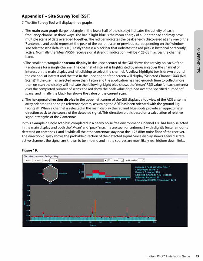
5: APPEN
DICES
Iridium Pilot™ Installation Guide 55
Appendix F – Site Survey Tool (SST)7. The Site Survey Tool will display three graphs:
a. The main scan graph (large rectangle in the lower half of the display) indicates the activity of each frequency channel in three ways. The bar in light blue is the mean energy of all 7 antennae and may have multiple scans of data averaged together. The red bar indicates the peak energy discovered at any one of the 7 antennae and could represent the peak of the current scan or previous scan depending on the “window size selected (the default is 10). Lastly there is a black bar that indicates the red peak is historical or recently active. Normally the “Mean” RSSI (receive signal strength indication) will be -123 dBm across the channel band.
b. The smaller rectangular antenna display in the upper center of the GUI shows the activity on each of the 7 antennae for a single channel. The channel of interest is highlighted by moussing over the channel of interest on the main display and left clicking to select the channel. A yellow highlight box is drawn around the channel of interest and the text in the upper right of the screen will display “Selected Channel: XXX (NN Scans)” If the user has selected more than 1 scan and the application has had enough time to collect more than on scan the display will indicate the following: Light blue shows the “mean” RSSI value for each antenna over the completed number of scans; the red show the peak value obtained over the specified number of scans; and finally the black bar shows the value of the current scan.
c. The hexagonal direction display in the upper left corner of the GUI displays a top view of the ADE antenna array oriented to the ship’s reference system, assuming the ADE has been oriented with the ground lug facing aft. When a channel is selected in the main display the red and blue spots provide an approximate direction back to the source of the detected signal. This direction plot is based on a calculation of relative signal strengths of the 7 antennas.
In this example a single scan has completed in a nearly noise free environment. Channel 130 has been selected in the main display and both the “Mean” and “peak” maxima are seen on antenna 2 with slightly lesser amounts detected on antennas 1 and 3 while all the other antennae stay near the -123 dBm noise floor of the receiver. The direction display shows the probable direction of the detected signal. Since display shows a few discrete active channels the signal are known to be in-band and in the sources are most likely real Iridium down links.
Figure 19.
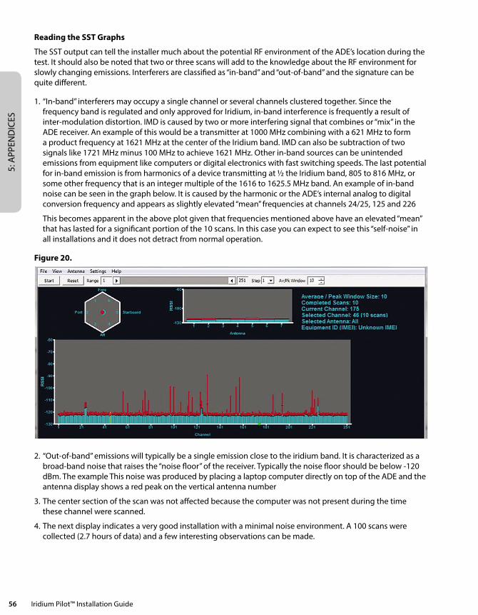
5: A
PPEN
DIC
ES
56 Iridium Pilot™ Installation Guide
Reading the SST Graphs
The SST output can tell the installer much about the potential RF environment of the ADE’s location during the test. It should also be noted that two or three scans will add to the knowledge about the RF environment for slowly changing emissions. Interferers are classified as “in-band” and “out-of-band” and the signature can be quite different.
1. “In-band” interferers may occupy a single channel or several channels clustered together. Since the frequency band is regulated and only approved for Iridium, in-band interference is frequently a result of inter-modulation distortion. IMD is caused by two or more interfering signal that combines or “mix” in the ADE receiver. An example of this would be a transmitter at 1000 MHz combining with a 621 MHz to form a product frequency at 1621 MHz at the center of the Iridium band. IMD can also be subtraction of two signals like 1721 MHz minus 100 MHz to achieve 1621 MHz. Other in-band sources can be unintended emissions from equipment like computers or digital electronics with fast switching speeds. The last potential for in-band emission is from harmonics of a device transmitting at ½ the Iridium band, 805 to 816 MHz, or some other frequency that is an integer multiple of the 1616 to 1625.5 MHz band. An example of in-band noise can be seen in the graph below. It is caused by the harmonic or the ADE’s internal analog to digital conversion frequency and appears as slightly elevated “mean” frequencies at channels 24/25, 125 and 226
This becomes apparent in the above plot given that frequencies mentioned above have an elevated “mean” that has lasted for a significant portion of the 10 scans. In this case you can expect to see this “self-noise” in all installations and it does not detract from normal operation.
Figure 20.
2. “Out-of-band” emissions will typically be a single emission close to the iridium band. It is characterized as a broad-band noise that raises the “noise floor” of the receiver. Typically the noise floor should be below -120 dBm. The example This noise was produced by placing a laptop computer directly on top of the ADE and the antenna display shows a red peak on the vertical antenna number
3. The center section of the scan was not affected because the computer was not present during the time these channel were scanned.
4. The next display indicates a very good installation with a minimal noise environment. A 100 scans were collected (2.7 hours of data) and a few interesting observations can be made.
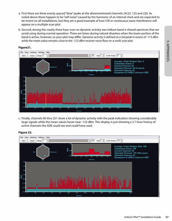
5: APPEN
DICES
Iridium Pilot™ Installation Guide 57
a. First there are three evenly spaced “blue” peaks at the aforementioned channels 24/25, 125 and 226. As noted above these happen to be “self noise” caused by the harmonic of an internal clock and are expected to be resent on all installations, but they are a good example of how CW or continuous wave interference will appear on a multiple scan plot.
b. Second, during this nearly three hour scan no dynamic activity was Iridium band is shared spectrum that we avoid using during normal operation. There are times during natural disasters when the lower portion of the band is active, however, so your plot may differ. Dynamic activity is defined as a red peak in excess of -115 dBm while the mean value remains close to the -123 dBm receiver noise floor on a multi scan plot.
Figure21.
c. Finally, channels 60 thru 251 show a lot of dynamic activity with the peak indication showing considerably large signals while the mean values hover near -123 dBm. This display is just showing a 2.7 hour history of active channels the ADE could see and could have used.
Figure 22.
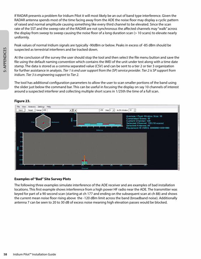
5: A
PPEN
DIC
ES
58 Iridium Pilot™ Installation Guide
If RADAR presents a problem for Iridium Pilot it will most likely be an out of band type interference. Given the RADAR antenna spends most of the time facing away from the ADE the noise floor may display a cyclic pattern of raised and normal amplitude causing something like every third channel to be elevated. Since the scan rate of the SST and the sweep rate of the RADAR are not synchronous the affected channels may “walk” across the display from sweep to sweep causing the noise floor of a long duration scan (> 10 scans) to elevate nearly uniformly.
Peak values of normal Iridium signals are typically -90dBm or below. Peaks in excess of -85 dBm should be suspected as terrestrial interferers and be tracked down.
At the conclusion of the survey the user should stop the tool and then select the file menu button and save the file using the default naming convention which contains the IMEI of the unit under test along with a time date stamp. The data is stored as a comma separated value (CSV) and can be sent to a tier 2 or tier 3 organization for further assistance in analysis. Tier 1 is end user support from the (SP) service provider. Tier 2 is SP support from Iridium. Tier 3 is engineering support to Tier 2.
The tool has additional configuration parameters to allow the user to scan smaller portions of the band using the slider just below the command bar. This can be useful in focusing the display on say 10 channels of interest around a suspected interferer and collecting multiple short scans in 1/25th the time of a full scan.
Figure 23.
Examples of “Bad” Site Survey Plots
The following three examples simulate interference of the ADE receiver and are examples of bad installation locations. This first example shows interference from a high power HF radio near the ADE. The transmitter was keyed for part of a 90 second scan (starting at ch 177 and ending on the subsequent scan at ch 88) and shows the current mean noise floor rising above the -120 dBm limit across the band (broadband noise). Additionally antenna 7 can be seen to 20 to 30 dB of excess noise meaning high elevation passes would be blocked.
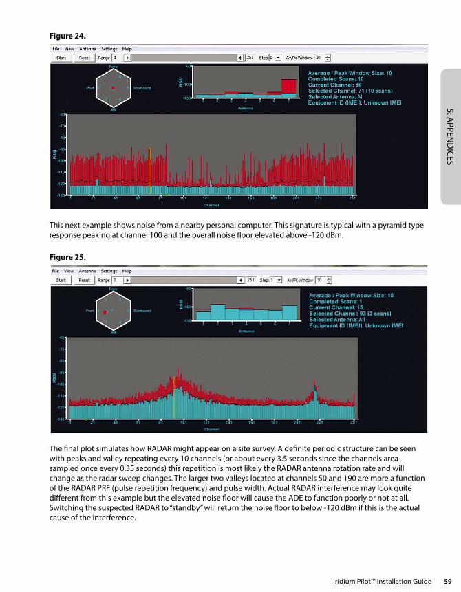
5: APPEN
DICES
Iridium Pilot™ Installation Guide 59
Figure 24.
This next example shows noise from a nearby personal computer. This signature is typical with a pyramid type response peaking at channel 100 and the overall noise floor elevated above -120 dBm.
Figure 25.
The final plot simulates how RADAR might appear on a site survey. A definite periodic structure can be seen with peaks and valley repeating every 10 channels (or about every 3.5 seconds since the channels area sampled once every 0.35 seconds) this repetition is most likely the RADAR antenna rotation rate and will change as the radar sweep changes. The larger two valleys located at channels 50 and 190 are more a function of the RADAR PRF (pulse repetition frequency) and pulse width. Actual RADAR interference may look quite different from this example but the elevated noise floor will cause the ADE to function poorly or not at all. Switching the suspected RADAR to “standby” will return the noise floor to below -120 dBm if this is the actual cause of the interference.
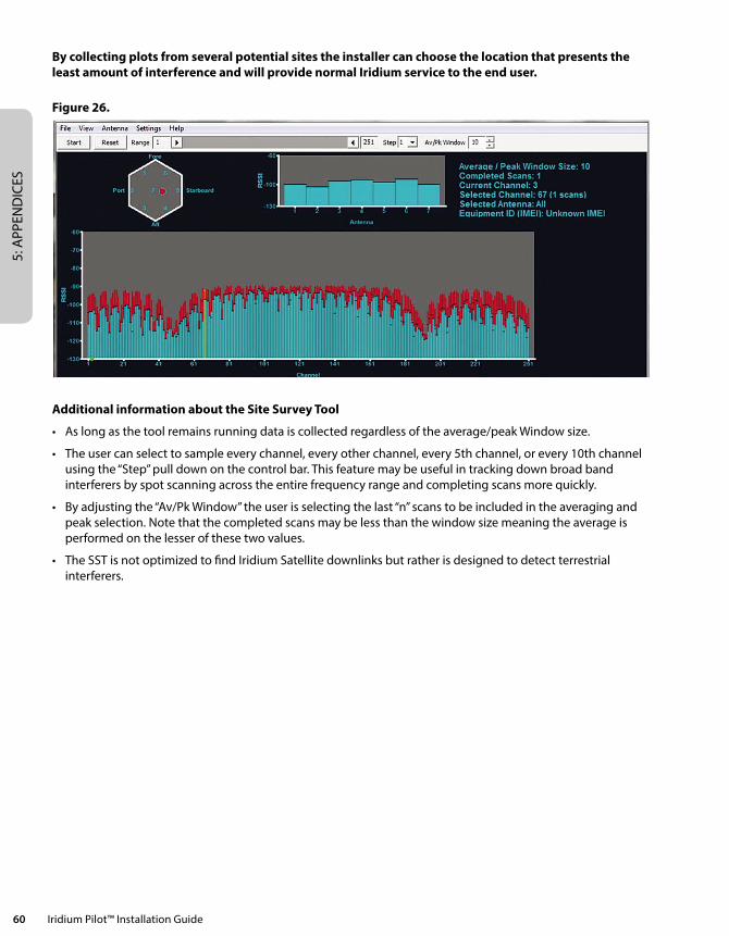
5: A
PPEN
DIC
ES
60 Iridium Pilot™ Installation Guide
By collecting plots from several potential sites the installer can choose the location that presents the least amount of interference and will provide normal Iridium service to the end user.
Figure 26.
Additional information about the Site Survey Tool
• Aslongasthetoolremainsrunningdataiscollectedregardlessoftheaverage/peakWindowsize.
• Theusercanselecttosampleeverychannel,everyotherchannel,every5thchannel,orevery10thchannelusing the “Step” pull down on the control bar. This feature may be useful in tracking down broad band interferers by spot scanning across the entire frequency range and completing scans more quickly.
• Byadjustingthe“Av/PkWindow”theuserisselectingthelast“n”scanstobeincludedintheaveragingandpeak selection. Note that the completed scans may be less than the window size meaning the average is performed on the lesser of these two values.
• TheSSTisnotoptimizedtofindIridiumSatellitedownlinksbutratherisdesignedtodetectterrestrialinterferers.


![Index []€¦ · Globalstar SatFi Iridium GO! 2 IP-based satellite devices include (but are not limited to): Inmarsat FBB, BGAN, IsatPhone Pro Iridium Pilot/OpenPort Iridium 9555,](https://img.pdfslide.net/doc/110x75/5f7ac1271bddb8717670f952/index-globalstar-satfi-iridium-go-2-ip-based-satellite-devices-include-but.jpg)