Embed Size (px)
Citation preview
US DEPARTMENT OF AGRICULTURESOIL CONSERVATION SERVICE
IRRIGATION DIVERSION STRUCTURECOMMITTEE
REPORT
I J
I I/ /
Sluice
Vortex tube·
r---- Sediment box
~- Canal
August 28, 1992
. I
I
k... ·'·,;
. ,
IRRIGATION DIVERSION STRUCTURE COMMITTEEReport',
'I
" I
" .
.'Ii I.
IRRIGATION DIVERSION S7RUCTURE COMMITTEEReport
TABLE OF CONTENTS
, I • I
Introduction ..•..•••••••••••••••••••••••••..•Background •••••••••••••••••••••••••••••••••••Objectives ••••••••••••••••••••••.•••.••••••••Definitions ••••••••••••• ~~_~~ •••• ~ •• s.ss,~$"Diversion categories •••••••••••••••••••••••••Stream Characteristics and DiversionConsiderations .••••••••••••••••••••••••••..••Types of Diversion Structures ••••••••••••••••Service Life .Low Initial Cost Irrigation DiversionStructure Concepts •••••••••••••••••••••••••••Check devices '.. e ., eI l:l • = D CjII 0 II Q ••••••••••
Conclusions •.•••.•.•••••.••.••.••••••••.• a •••
Recommendations ••••••••••••••••••••••••••••••
A.B.C.D.E.F.
G.H.I.
J.K.L.M. Acknowledgements •••••••••• • • • • • 0 • • • • 0 • • • • • • • •
11233
345
55678
Appendix I - Tables.Table 1- Diversion Categories - Head vsDiversion Material •••••••••••••••••••••••••••Table 2 - Diversion Structures Material byLife .
Appendix II - Concepts.
Infiltration Gallery •••••••••••••••••••••••••Vortex Tube Gallery ••••••••••••••••••••••••••Steel Plate ••..•...••••...•....•.••.••••..•..Mass Foundation and Check ••••••••••••••••••••Pile/Post Foundation and Check•••••••••••••••l?ll~l? ••••••••••••••••••••••••••••••••••••••••
Appendix III - Checks.
Jack and Stoplog/~imberCheck••••••••••••••••Inflatable Fabric Check ••••••••••••••••••••••Log Check•••••••.••••••••.•.•••••••••••••••••Lift Panel Check•••••••••••••••••••••••••••••Prefabricated Beam Check•••••••••••••••••••••Swinging Pipe Check••••••••••••••••••••••••••Wire Fencing and Geosynthetic Check••••••••••
I-l
1-2I
,II1I-1 II11-9
:111-16 ,I1I-211I-311I-38
I11-1111-3111-51II-71II-9III-111II-13
\
t" .),.,....
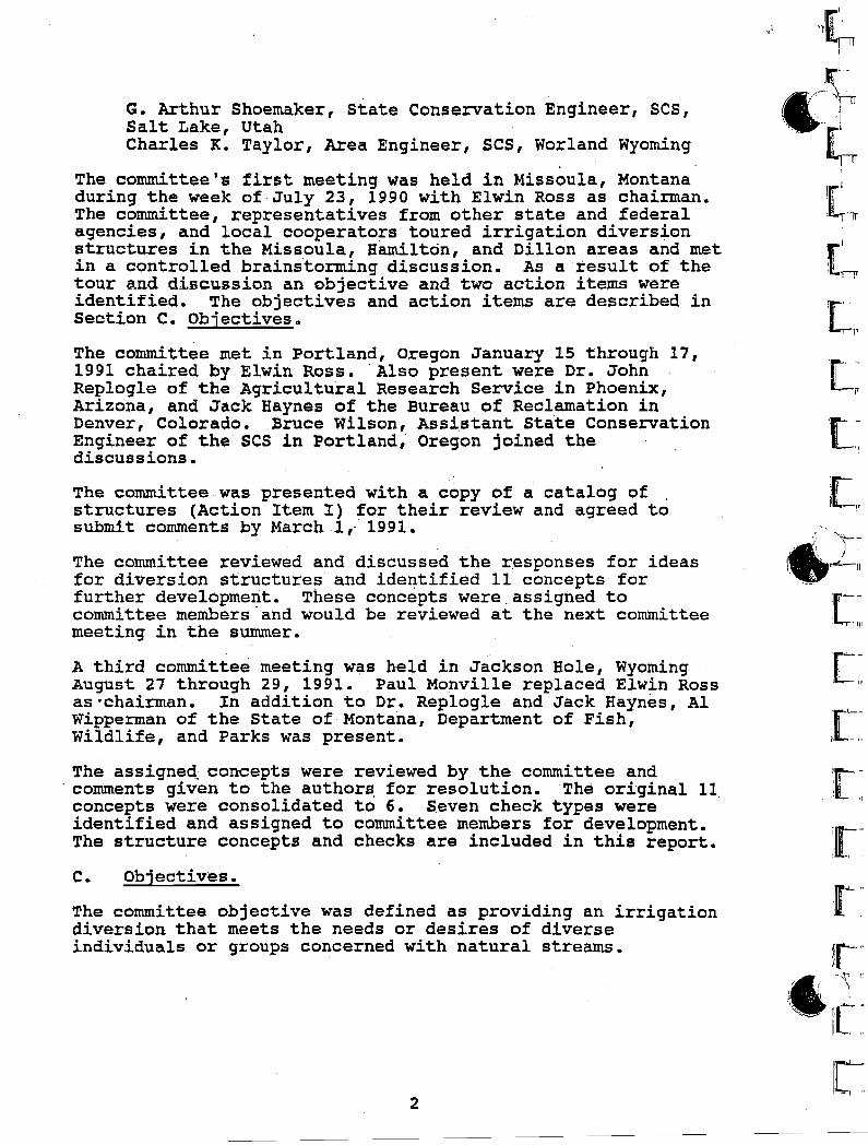
IRRIGATION DIVERSION STRUCTURE COMMITTEEReport
July 17, 1992
A. Introduction.
Many irrigation diversion structures in the western stateswere established in the late 1800s and early 1900s. Thesesites may have been established with permanent structural
. works across the stream or consisted of a canal or ditchintersecting the stream channel. Many of the diversion sitesare located on rivers or streams that have had degradation ofthe channel bottom. With the channel degradation andresulting lowering of the water level in the stream, thedesired irrigation flow can no longer be diverted. Tocompensate .for this loss of head some Irrigation Districts(Companies) and/or individual owners have entered the riversor streams annually to build, extend or repair grave.ldiversions in order to direct and raise the water to theirintake structures.. In most cases this work has been donewithout permits, such as the 404 permit, being obtained. Somestates have instigated or are instigating legisl~tion toprohibit this practice. AS the building of gravel diversionsis prohibited these owners will be required to install othermeasures to divert and/or raise water levels. Also theconstruction of permanent headwalls with large drops across astream is not always the desired solution. Recreationalconsiderations such as canoeing and rafting, and fishmigration need to be evaluated.
Current SCS criteria and pract~ces often dictate that newstructures will be costly. There is a need in the SCS todevelop low cost alternative structures accepting highermaintenance in place of high initial cost. The IrrigationDiversion Structure Committee was formed to identify possiblealternative structure types.
E. Background.
Discussions were held between Richard Gooby, StateConservationist, Montana, and William Evans, Head, EngineeringStaff, WNTC in January 1990 and a committee formed toinvestigate the problem. The' committee members were confirmedMarch 29, 1990 and informed of a pending meeting in the summerof 1990. The committee members were as follows:
i.1
, /
Lewis L. Eurton, Design Engineer, SCS, Bozeman, MontanaPaul J. Monville, Civil Engineer,'SCS, WNTC, Portland,Oregon'Keith M. Robertson, District Conservationist, SCS,Hamilton, MontanaElwin A. Ross, Irrigation Engineer, SCS, WNTC, Portland,Oregon
1
I
, \
G. Arthur Shoemaker, State Conservation Engineer, SCS,Salt Lake, UtahCharles K. Taylor, Area Engineer, SCS, Worland Wyoming
The committee's first meeting was held in Missoula, Montanaduring the week of July 23, 1990 with Elwin Ross as chairman.The committee, representatives from other state and federalagencies, and local cooperators toured irrigation diversionstructures in the Missoula, Hamilton, and Dillon areas and metin a controlled brainstorming discussion.. As a result of thetour and discussion an objective and two action items wereidentified. The objectives and action items are described inSection C. Objectives.
The committee met in Portland, Oregon January 15 through 17,1991 chaired by Elwin Ross. 'Also present were Dr. JohnReplogle of the Agricultural Research Service in Phoenix,Arizona, and Jack Haynes of the Bureau of Reclamation inDenver, Colorado. Bruce Wilson, Assistant State ConservationEngineer of the SCS in Portland,' Oregon joined thediscussions.
The committee was presented with a copy of a catalog ofstructures (Action Item I) for their review and agreed tosubmit comments by March ,1" 1991.
The committee reviewed and discussed the r:esponses for ideasfor diversion structures and ide~tified 11 concepts forfurther development. These concepts were .. assigned tocommittee members 'and would be reviewed at the next committeemeeting in the summer.
A third committee meeting was held in Jackson Hole, WyomingAugust 27 through 29, 1991. ,Paul Manville replaced Elwin Rossas·chairman. In addition to Dr. Replogle and Jack Haynes, AlWipperman of the State of Montana, Department of Fish,Wildlife, and Parks was present.
The assigneq: concepts were reviewed by the committee andcomments given to the author~ for resolution. The original 11concepts were consolidated to 6. Seven check types wereidentified and assigned to committee members for development.The structure concepts and checks are included in this report.
C. Objectives.
The committee objective was defined as providing an irrigationdiversion that meets the needs or desires of diverseindividuals or groups concerned with natural streams.
2
[,1
r_:\[~
1["{''';:~-•' \ )
\, _~ , ,-!.r-I\
'rL-'1;
'[-',; II'
,:[":,',[--, I,". - '1
"I.e...-'j
:: " "
r-"
Ir"--I,l"
1\0
In order to help the committee accomplish their objective twoaction items were defined as follows:
1. Action Item I. Collect and consolidate examples of allirrigation diversions from the western states. Thiswould include both existing "standard" structures and"designed" structures.
2. Action Item II. Identify new and innovative ideas/concepts/criteria for "low cost" environmentally soundirrigation diversions.
1'1, I.
./'),.. ./
r. .,.. ')
To satisfy action item I the committee solicited drawings forirrigation diversion structures from the west states; prepareda catalog of these drawings, entitled West States IrrigationDiversion Structure Catalog; and distributed the catalog tothe western states by West NTC Bulletin No.W210-1-15 datedApril 30, 1991.
To satisfy action item II the committee solicited responsesfrom the SCS and other federal and state agencies for ideas onnew and innovative low cost structures; discussed these ideasin the subsequent meetings; and developed concepts to meet the .objectives. These concepts are anticipated to be used by thestates to develop standards. The development of the conceptsis described in the remainder of the report.
D. Definitions.
Check. A permanent or temporary irrigation diversion dam.Foundation. A base in the streambed to which a check is
attached.Gallery. A water collection system constructed beneath the
stream invert.Head. The depth of water at the diversion available for• delivering the 'required irrigation flow to the system.Horizontal gallery. A gallery that extends horizontally
across the streambed.Inflatable fabric. An enclosed material which when filled
with water will act as a check.Jacks. A series of braced supports for flashboard checks.Lift panels. Also called an overshot gate. A fabricated
panel hinged at the upstream end at the canal invert andraised or lowered with a cable fastened at the downstreamend.
Low cost. Low initial construction/installation cost.Non-obstructive diversion. A structure that is capable of
diverting irrigation flow without impeding the flow inthe stream.
Obstructive diversion. A structure that will impede thestream flow in order to divert for irrigation purposes.
Permanent check. A check that cannot easily be removed orlowered.
3
, I,I 'I '
,11·
I ''i
I
I,
I ,I
, I
II '" '
Pipe gallery. A water collection system beneath the streambedgenerally composed of perforated conduit embedded in arock or gravel envelope.
Temporary check. A check structure that can be easily removedor lowered.
Vertical gallery. An infiltration gallery that extendsvertically to the streambed.
Vortex tube. A slotted conduit across the streambed thattransports water and sediment with a spiral action~
Ea Diversion Categories.
Irrigation diversion structures can be divided into fourcategories of head as follows:
...",.
a"~ 0 to 3 feetb. 3 to 6 feet.c. 6 to 10 feet.d. Greater than 10 feet
Types of materials to construct diversions in the fourcategories are given in Table 1 - Diversion Categories - Headvs. Diversion Materials in Appendix I - Tables.
As the head increases the complexity of the structure alsoincreases. It is concluded that the 0 to 3 feet category mostlikely contains the low initial cost structures and isconsistent with the objective. These structures generallyrequire high maintenance.
F. Stream Characteristics and Diversion Considerations.
An understanding of stre~ characteristics is necessary toev~luate diversion alternatives. Stream characteristicsconsidered include bed material, slope, fish moveme'nt,bed/bank stability, recreation use, seasonal flow, and peakflows. Diversion considerations include discharge, period ofoperation,w:p.ter quality, and stream user needs.
G. Types of Diversion Structures.
For purposes of this report irrigation diversions areclassified as non-obstructive or obstructive. Galleries andpumps are considered non-obstructive types. Dams or checksare considered obstructive types. The obstructive types arefurther subdivided into temporary, permanent or a combinationof each type.
In non-obstructive structures discharge is the major designconsideration rather than the available head. Gallerystructures may be horizontal or vertical. Horizontalgalleries may be constructed of pipe, timber cribbing, frenchdrain, or geotextile fabric. Vertical galleries may be
4
irr
~ltIIIillirei"i'[" -, Il[
,if 'Il-n
~l" r')
(...."t
::r~
l,c
I-t, IL
H. Service Life
t
l, .'I
"
,I,
,Ii
1'
Short lifeMedium lifeLong life
o to 5 years5 to 20 yearsGreater than 20 years
Service Life, as defined in some SCS practices, is classifiedas short, medium and long. For purposes of classifyingdiversion structures the following period of time is assignedto each.
constructed of pipe, steel sheet pile, and timber cribbing orpiling.
Temporary obstructive structures have checks that may beremoved from the stream cross section when not diverting forirrigation. These structures consist of a foundation or baseand a removable check such as jacks with stoplogs. Thefoundation may be constructed of steel plate, concrete, looserock, timber, pipe, grouted rock, gabion, steel piling orposts, and timber piling or posts.
Permanent obstructive structures are dams that will remain inplace. These structures may 'be constructed of the samematerial as used for the temporary obstructive structures.
Combinations of permanent ahd temporary obstructive structuresmay be used in a single diversion structure.
t :,'/
\,
A list of structures constructed of various materials and'classified by type and service life was developed and is givenin Table 2 - Diversion Structures - Material by Life.Examination of the table leads to the conclusion that a lowcost diversion structure generally has a life of 5 to 20years, or even may be reinstalled annually ••
. \
I. Low Initial Cost Irrigation Diversion Struc~uie Concepts.
As developed in the previous sections the typical range ofhead for low cost diversion structures is 0 to 3 feet. Thestructures in this range of head are generally rated as shortto medium life structures.
Based on the above criteria the following concepts have beendeveloped.
1.
2.
Infiltration Gallery
Vortex Tube Gallery
Steel Plate
Mass Foundation and Check
5
s.6.
Pile/Post Foundation and Check
Pump Plant
,~">l·w11'1
•' «1n!
:"-., "tJThe description of the structure concepts, including sketches,planning considerations, and design criteria andspecifications are given in Appendix II - Concepts.
J. Check devices.
Check devices are generally used with temporary obstructivetype diversions with a permanent foundation. These checksinclude th~ following types:
1. Jack ~~d stoploq/timbercheck
2. Inflatable fabric check
uuu[j
6
5. Prefabricated beam check
'K. Conclusions.
Design criteria and specifications are giv~n for each of theabove checks in Appendix III - Checks.
( 'i,-J
[J
1\ /\h~,,~J
t:totor:
!
I-I! LJ
[J
,> In._:d,'l.J[]
Log check
Lift panel check
3.
1. Interaction with outside agencies and interests is veryproductlve.
4.
3. Low cost irrigation structures can be defined andspecific types can be developed.
4. The committee recognizes that there may be other feasibleconcepts for low cost diversion structures rather thanthose developed.
,..2. The Irrigation Diversion Structure catalog will fill a
need 'in the sese
Based on the meetings and development of the structures thecommittee has made the following conclusions:
As a result of interaction with representatives from otherstate and federal agencies, and local cooperators in theMissoula, Hamilton, and Dillon areas the committee was able toestablish objectives that met the diverse concerns of thevaried groups. The participation of Dr. John Replogle and
6. Swinging pipe check
7. Wire fencing and geosynthetic check
Jack Haynes in the Portland and Jackson meetings provided\ technical input that assisted the committee in the development
of the concepts presented. Al Wipperman providedenvironmental balance to the committee's efforts in theJackson meeting.
The response from recipients of the Irrigation DiversionStructure catalog is that it will be helpful in the selectionand design of diversion structures. This response leads tothe conclusion that the preparation of the catalog was timelyand worth while. .
The committee's greatest effort was concentrated on definingand developing specific types of low cost environmentallysound irrigation diversion structures through theidentification of their characteristics as follows:
1. The typical range of available head is 0 to 3 feet,except for non-obstructive structures where discharge isthe major design consideration rather than the availablehead.
2. Generally the life is 5 to 20 years, or it may bereinstalled annually. These are rated as short to mediumlife structures.
IiiI, ~II,;
,'Iii' ...,.1 i
ii'", II I
~ :, . I
t I
I I, I
II
1\'IiI, '
I
~" .. 3.
4.
The structures are usually the non-obstructive ortemporarily obstructive type. Obstructive typediversions are generally not environmentally acceptableand other types should be investigated when possible.
Six types of irrigation diversion structures wereselected as meeting the requirements of low cost andenvironmentally sound.
5. Seven check devices were selected to be Used withfoundations of temporary obstructive diversions:
Descriptions including sketches, planning considerations, anddesign criteria and specifications have been developed foreach of the six types of diversion structures. Thisinformation is given in Appendix II - Concepts.
Design criteria and specifications for each of the seven checkdevices have been developed and included in Appendix III Checks. Also included are descriptions, sketches, references,and costs.
Two other types of structures were discussed during themeetings and considered usable where applicable. These'structures were the Reichmuth Diversion and a thin plainconcrete hard section. The Reichmuth Diversion is a rock
.gradient control using large rock in a "v" formation in plan, with the closed end of the "v" facing upstream. This type of
7
, ,
i: II,
I !
2.
structure is similar to the mass foundation using rock and was'not introduced as a separate type of structure. The thinplain concrete hard section is similar to the mass foundationusing plain concrete and could be used in it's place.
L. Recommendations.
The following recommendations are a_product of the committee'sdiscussions and conclusions:
The structure and check information given in Appendix IIand III should be distributed to the western-states andto other interested parties outside of the sese
The states should be advised that the informationprovided may be used to develop state standards.
3. The users should be made aware of potential fordegradation and aggradation of the stre~ when disturbedby the construction and operation of diversions.
4. A search should be continued for other solutions to theproblem of irrigation diversion structures, i.e •• 'development of sketches and criteria for the Reichmuthdiversion and thin plain concrete sections.
5. A periodic update of the Irrigation Diversion structureCatalog should be made.
6. Revision of National Standards for temperature steelrequirements for short life reinforced concrete nonstructural slabs should be considered.
7. Revision of SCS standards should be considered to includeboth thick and thin plain concrete sections in highmaintenance irrigation diversion structures.
M. Acknowledgements.
The committee commends the following persons for theircontributions to the concepts presented:
Jack A. Haynes, Civil Engineering Technician, USDI,Bureau ofRecl~ation, Denver Colorado
Dan Merkel, Environmental Protection Agency, Denver, Colorado
John Peters, Environmental ~rotection Agency, Denver Colorado
John Replogle, Research Hydraulic Engineer, AgriculturalResearch Service, Phoenix, Arizona
D. James Suit, State Conservation Engineer, Soil ConservationService, Bozeman, Montana
8
, 1r "11,'('",:r,--\p;/1 ", J''''l!!! -r l
l~
_I
Lj1[~
l[~
I::C'
rL:a:If"':~,
rr
~C-
'{~
~' .... /." ,/I
\
Al Wipperman, state of Montana, Department of Fish, Wildlife,and Parks, Helena, Montana
\ ,
,.' Bruce Wilson, Assistant State Conservation Engineer, SoilConservation Service, Portland, Oregon
Lowell Kenedy, State Design Engineer, Soil ConservationService, Salt Lake City, utah
7- /7-~edate
fS-lc-4Ldate
Elwin A. Ross, member7-/7- 92-
date
G. Arthur Shoemaker, membera/;?!9e...
I date
~~d~7ciateCharles K:TaY ~r
I,
I I
. i
I
I'
9
I
; I.11
!
1 i
i ;i!1IiIii,
I1I1
:~...
Appendix I~ables
,o' '1
)
-!-I
I
:1'iI,
~~'~1
iI
',i ,i
Steel - prefab Concrete Masonry
Gabion Steel
. >10 Feet
Gabion/Concrete Concrete
Steel RCC
Concrete Pumps
RCC Dams
Pumps Sheet Pile
DIVERSION CATEGORIESHead vs. Diversion Material
:rable 1
Concrete
Grouted Rock
Pumps
Head3 toG Feet 6 to 10 Feet
Timber
Sack Crete
Cone/masonry/block
Sack Crete
o TO 3 Feet
Fabric Loose Rock
Loose Rock
Pipe
. Logs and Timber Gabion/Rock
~
.,: \ I ::::~ _ Wire/Rock etc.
L. '
1;1I.;
iI',1'1; I iI, I, I
I-I
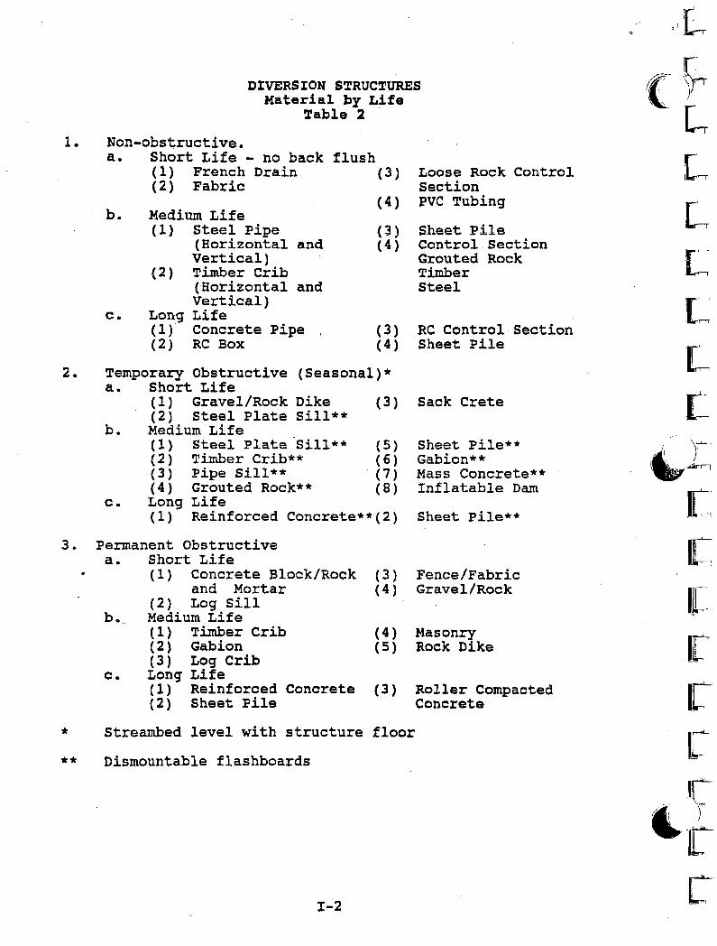
DIVERSION S~RUC~URES
Material by Life~able 2
1. Non-obstructive.a. Short Life - no back flush
(1) French Drain (3) Loose Rock Control(2) Fabric Section
(4) PVC Tubingb. Medium Life
(1) Steel Pipe (3) Sheet pile(Horizontal and (4) Control SectionVertical) Grouted Rock
(2) Timber Crib Timber(Horizontal and SteelVertical)
c. Long Life(1) Concrete Pipe (3) RC Control, Section(2 ) RC Box (4) Sheet Pile
2. Temporary Obstructive (Seasonal)*a. Short Life
( 1 ) Gravel/Rock Dike (3) Sack Crete(2) Steel Plate Sill**
b. Medium Life( 1 ) Steel Plate 'Sill** (5) Sheet Pile**(2) Timber Crib** ( 6 ) Gabion**(3) Pipe Sill** (7) Mass Concrete**(4) Grouted Rock** (8) Inflatable Dam
c. Long Life(1 ) Reinforced Concrete**(2) Sheet Pile**
3. Permanent Obstructivea. Short Life
(1) Concrete Block/Rock (3) Fence/Fabricand Mortar (4) Gravel/Rock
(2) Log sillb. Medium Life
(1) Timber Crib (4) Masonry(2) Gabion (5) Rock Dike(3) Log Crib
c. Long Life(1 ) Reinforced Concrete (3) Roller Compacted(2) Sheet pile Concrete
* Streambed level with structure floor
** Dismountable flashboards
1-2
r'([[,
LL'L[~
t,lit, y-,'.........,
[I
ICr,Ifterlr
'tC
I'I
"
I.'
Appendix IIConcepts
,I!
ij.:!I
,.1 r
I11[,
, ', I, ;
"
Ii,I,
,I I
I
".
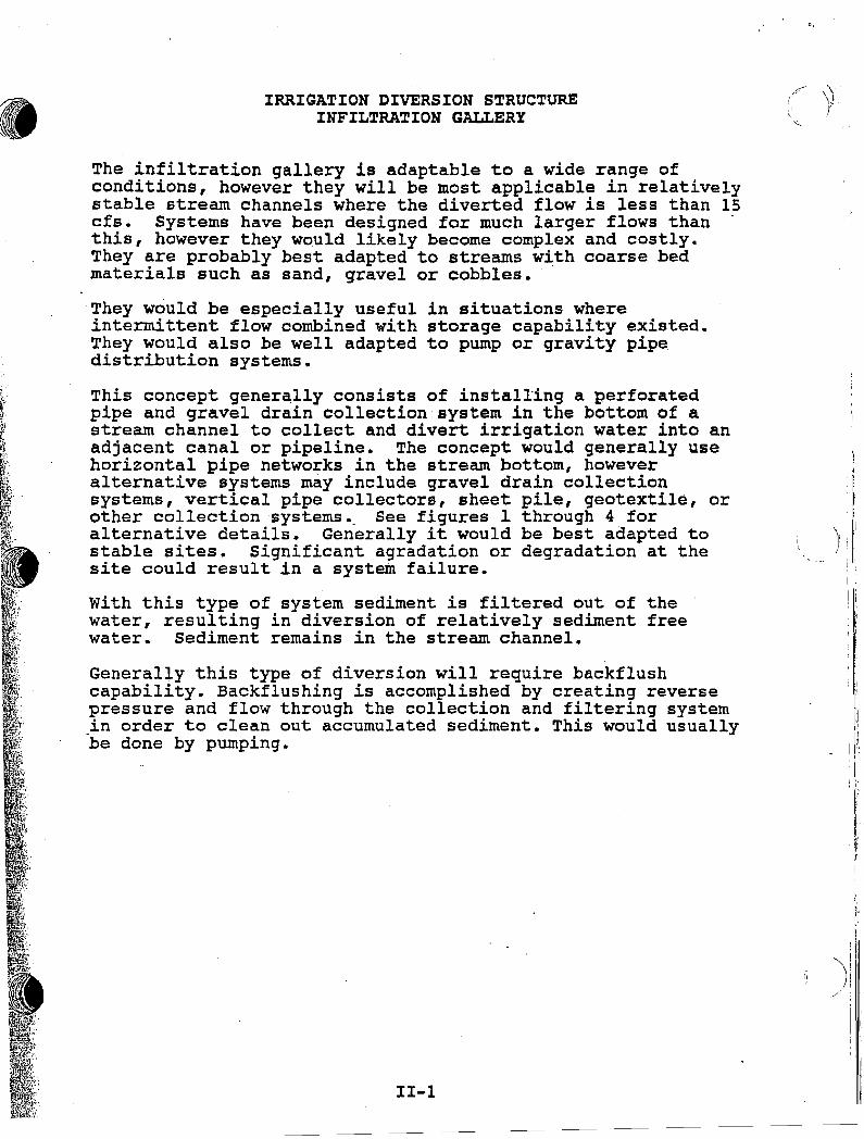
IRRIGATION DIVERSION STRUCTUREINFILTRATION GALLERY
The infiltration gallery is adaptable to a wide range ofconditions, however they will be most applicable in relativelystable stream channels where the diverted flow is less than 15cfs. Systems have been designed for much larger flows than .this, however they would likely become complex and costly.They are probably best adapted to streams with coarse bedmaterials such as sand, gravel or cobbles.
They would be especially useful in situations whereintermittent flow combined with storage capability existed.They would also be well adapted to pump or gravity pipedistribution systems.
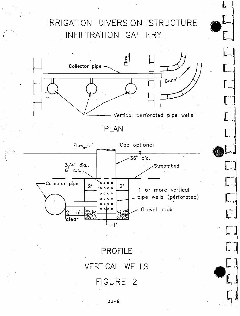
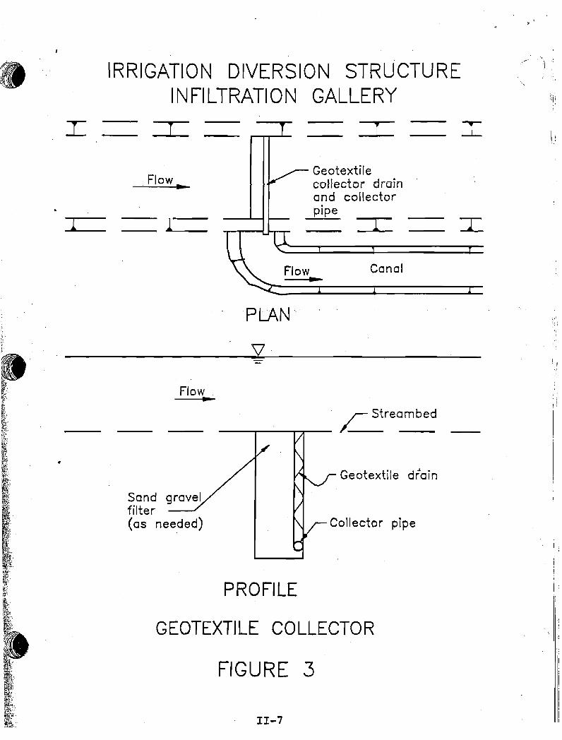
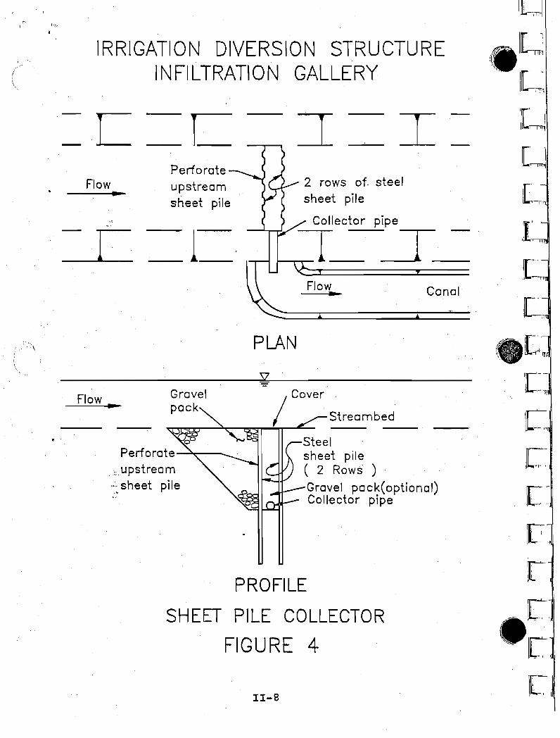
This concept generally consists of installing a perforatedpipe and gravel drain collection system in the bottom of astream channel to collect and divert irrigation water into anadjacent canal or pipeline. The concept would generally usehorizontal pipe networks in the stream bottom, howeveralternative systems may include gravel drain collectionsystems, vertical pipe collectors, sheet pile, geotextile, orother collection systems •. See figures 1 through 4 foralternative details. Generally it would be best adapted tostable sites. Significant agradation or degradation at thesite could result in a system failure.
With this type of system sediment is filtered out of thewater, resulting in diversion of relatively sediment freewater. Sediment remains in the stream channel.
Generally this type of diversion will require backflushcapability. Backflushing is accomplished by creating reversepressure and flow through the collection and filtering system,in order to clean out accumulated sediment. This would usuallybe done by pumping.
11-1
) :;1I
ii'II
i I"·
i,j:.
i'i
: :
)1'
; I, i
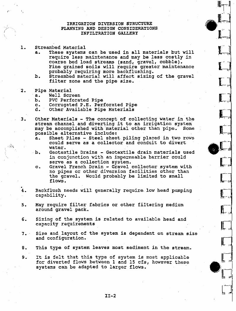
IRRIGATION DIVERSION STRUCTUREPLANNING AND DESIGN CONSIDERATIONS
INFILTRATION GALLERY
Streambed Materiala. These systems can be used in all materials but will
require less maintenance and may be less costly incoarse bed load streams (sand, gravel, cobble).Fine grained soils will require greater maintenanceprobably requiring more backflushing.
b. Streambed material will affect sizing of the gravelfilter zone and the pipe size.
(
1.
2. Pipe, a.b.c.d.
MaterialWell ScreenPVC Perforated PipeCorrugated P.E. P~rforated PipeOther Available Pipe Materials
~J
.~l.I-mI:'JII" ],~IL--"I1r'
3.
•4.
s.
6.
7.
8.
9.
Other Materials - The concept of collecting water in thestream channel and diverting it to an irrigation systemmay be accomplished with material other than pipe. Somepossible alternative include:a. Sheet Piles - Steel sheet piling placed in two rows
could serve as a collector and conduit to divertwater.
b. Geotextile Drains - Geotextile drain materials usedin conjunction with an impermeable barrier couldserve as a collection system. _
c. Gravel French Drain - Gravel collector system withno pipes or other diversion facilities other thanthe gravel. Would probably be limited to smallflows •
Backflush needs will generally require low head pumpingcapability.
May require filter fabrics or other filtering mediumaround gravel pack.
Sizing of the system is related to available head andcapacity requirements
Size and layout of the system is dependent on stream sizeand configuration.
This type of system leaves most sediment in the .stream.
It is felt that this type of system is most applicablefor diverted flows between 1 and 15 cfs, however thesesystems can be adapted to larger flows.
11-2
(!~,
'.····1(:\. __ .. Jkr-I- .
~.;...L ,, ,t , '.! .
[;
-1-..I ..~:. L.
I~ I
~-L
n~]
f,~ [~
ei
f]LJ!
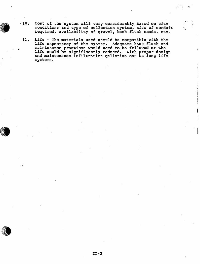
10. Cost of the system will vary considerably based on siteconditions and type of collection system, size of conduitrequired, availability of gravel, back flush needs, etc.
11. Life - The materials used should be compatible with thelife expectancy of the system. Adequate back flush andmaintenance practices would need to be followed or thelife could be significantly reduced. With proper designand maintenance. infiltration galleries can be long lifesystems.
II-3
4~
!I ~.
~--- "
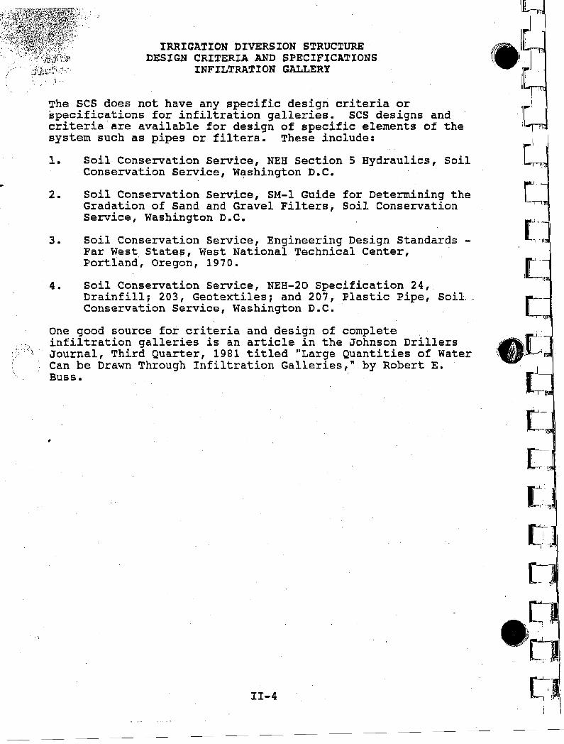
IRRIGATION DIVERSION STRUCTUREDESIGN CRITERIA AND SPECIFICATIONS
INFILTRATION GALLERY
The SCS does not have any specific design criteria orspecifications for infiltration galleries. SCS designs andcriteria are available for design of specific elements of thesystem such as pipes or filters. These include:
1. Soil Conservation Service, NEB section 5 Hydraulics, SoilConservation Service, W~shington D.C.
2. Soil Conservation Service, SM-l Guide for Determining theGradation of Sand and Gravel Filters, Soil ConservationService, Washington D.C.
3. Soil Conservation Service, Engineering Design Standards Far West states, West National Technical Center,Portland, Oregon, 1970.
4. Soil Conservation Service, NEH-20 Specification 24,Drainfill; 203, Geotextiles; and 207, Plastic Pipe, Soil,Conservation Service, Washington D.C •.
One good source for criteria and design of completeinfiltration galleries is an article in the Johnson DrillersJournal, Third Quarter, 19B1 titled "Large Quantities of WaterCan be Drawn Through Infiltration Galleries," by Robert E.~uss.
11-4
11[1er",iii. li!·1"t'
ill'e
.rJ
(.-n
[, -"-'.
: -'--11 .
L,,!'
ell.'·.; .
}t1.- i
{ {l.,:
~,L-1't,
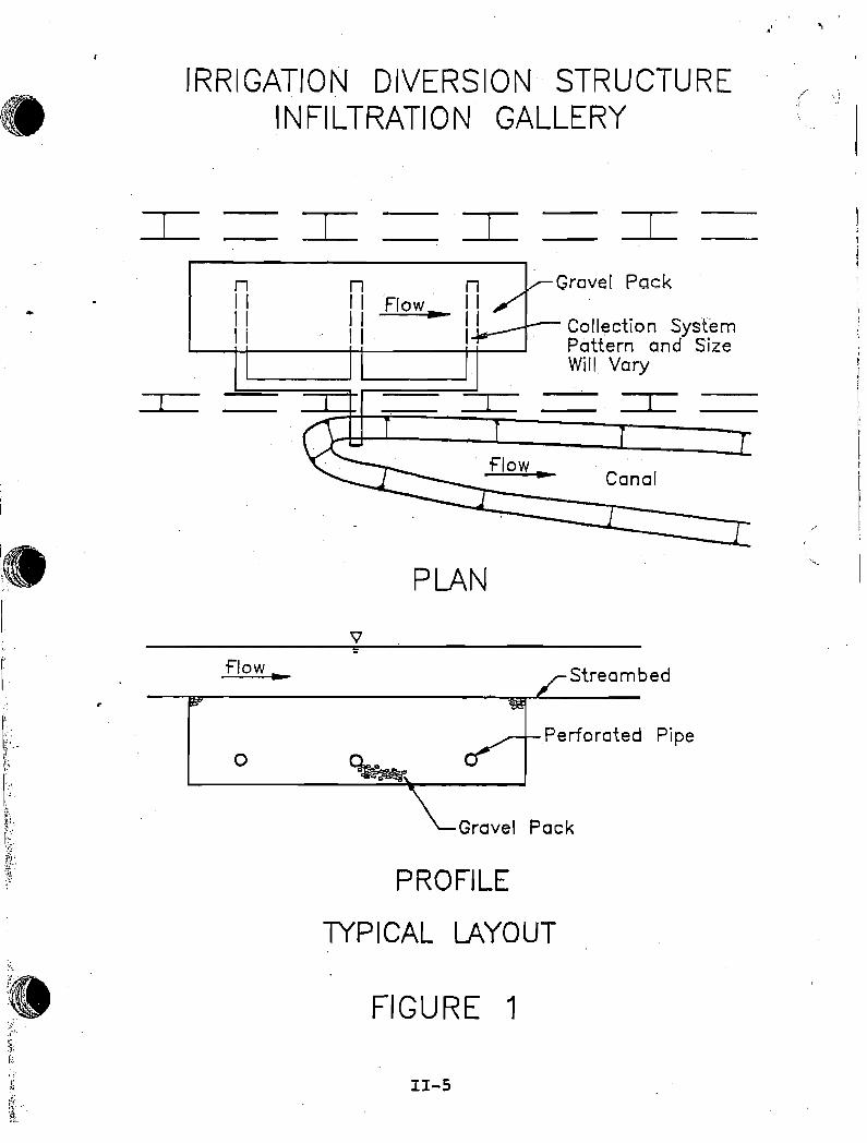
IRRIGATION DIVERSION STRUCTUREINFILTRATION GALLERY
.' 't
nI I
""Flow..
Collection SystemPattern and SizeWill Vary
::::r::
Canal
;.,~~'.~1;·'·I~·
~h1".
flow.
o
PLAN
Streambed
Perforated Pipe
Grovel Pock
PROFILE
I(PICAL LAYOUT
FIGURE 1
11-5
(I
\
I.'::'
IRRIGATION DIVERSION, STRUCTUREINFILTRATION GALLERY
•r-m
. r',l~
[
" '1
I~,I
1["I ,I -,--",
c-. I, ,
C[~
r·,'>, 'I'
[
•• 1
.} I It
•
' .• 1it... ";.'
ii!L,. !
I
Gravel pack
1 or more verticalpipe wells (perforated)
1'
II-6
o 0 0 0
2' 2''0 000
PROFILE
VERTICAL WELLS
FIGURE 2
0000
o 0 0 0
\--""----\ 0 0 0 0
Collector pipe
IRRIGATION DIVERSION STRUCTUREINFILTRATION GALLERY
I =r= =r= I
CanalFlow..
FlowGeotextilecoHector drain..and collectorpIpe
J 1 =r I.
PLAN·
SZ
11-7
Geotextile drain
Collector pipe
---,.-----r-,....._- L Strea mbed
FIGURE 3
PROFILE
GEOTEXTILE COLLECTOR
Flow..
Sand gravelfilter(as needed)
[~J
1["I -'-pn
,("'
'[~r\
[~r"
ll-J
•
.. [, I! \1T!Jl
". 1['I '"?:'1
Canal
I
Flow..
2 rows of. steelsheet pile
Collector pipe
r----r-o--=r 3 _
Perforateupstreamsheet pile
_ 1_
_L
IRRIGATION DIVERSION STRUCTUREINFILTRATION GALLERY
Flow..
=c
PLAN
11-8
PROFILE
SHEET PILE COLLECTOR
FIGURE 4
ie'._.-
t: ill
C,,C~'I
1[-t .~ -,' "'!
['~!I
['1
• etC: ,
, _-, I
ar- i!l-., '
Streambed
Steelsheet pile( 2 Rows· )
Gravel pack(optional)Collector pipe
Gravelpack
Perfarate ----"0,,-_.
,;, upstream",,:, sheet pile
Flow ..
~.
•/.::'."'.-.:.-'I ..
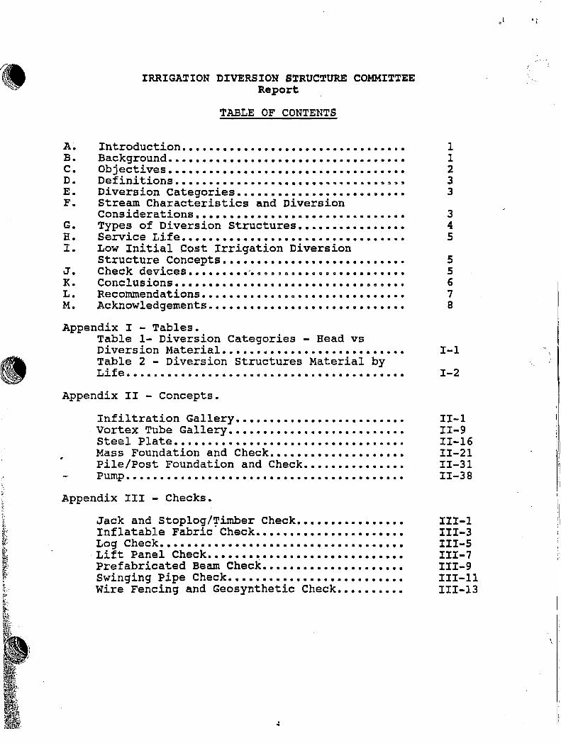
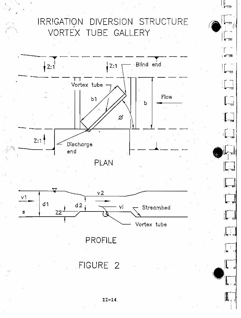
IRRIGATION DIVERSION STRUCTUREVORTEX TUBE GALLERY
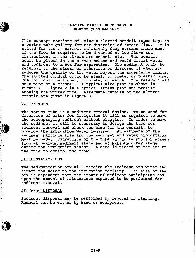
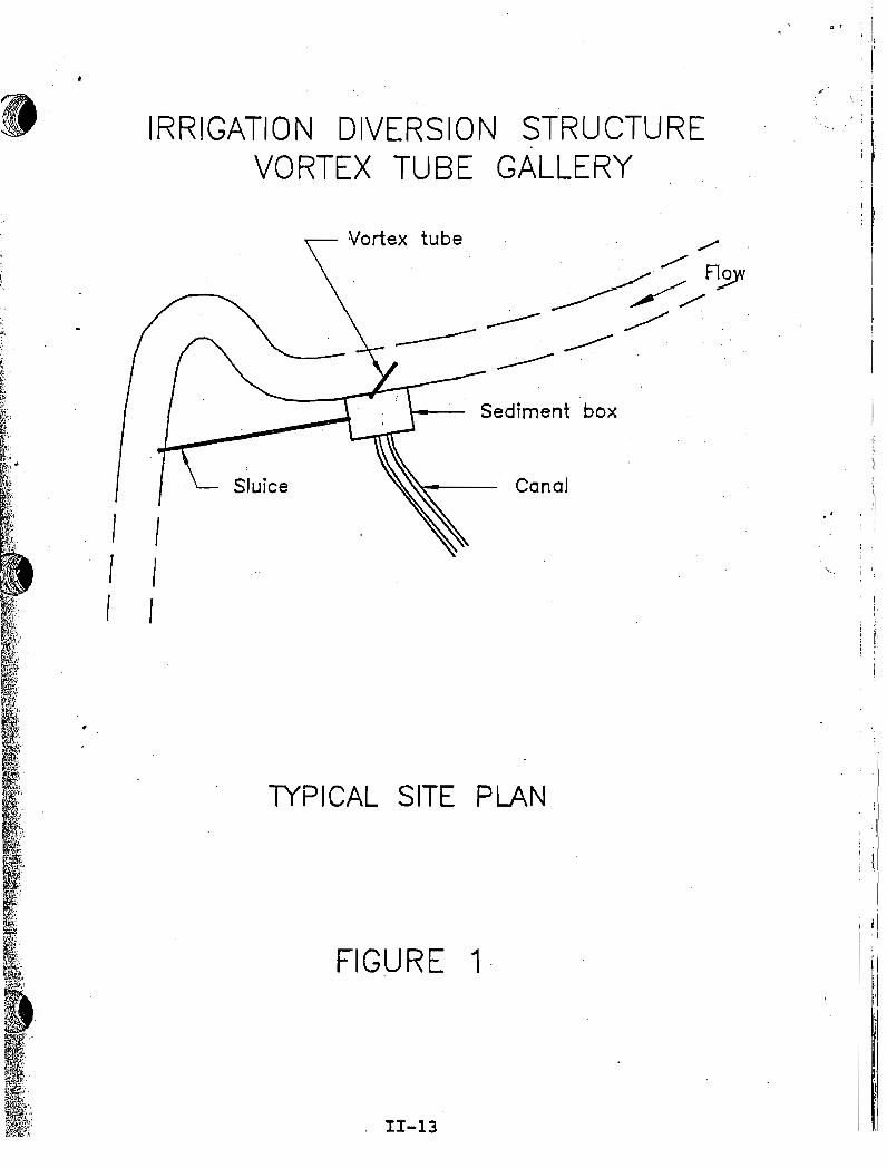
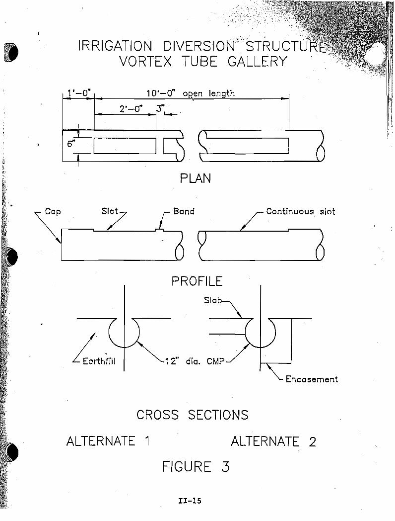
This concept consists of using a slotted conduit (open top) asa vortex tube gallery for the diversion of stream flow. It issuited for use in narrow, relatively deep streams where mostof the flow is required to be diverted at low flows andobstructions in the stream are undesirable. The conduitwould be placed in the stream bottom and would divert waterand sediment to a box for separation. The sediment would bereturned to the stream or otherwise be disposed of when itreduces the quality of the water beyond the acceptable limitsoThe slotted conduit could be steel, concrete, or plastic pipe.The box could be timber, concrete, or earth. The return couldbe a pipe or a channel. A typical site plan is·showninfigure 1. Figure 2 is a typical stream plan and profileshowing the vortex tube. Afternate details of the slottedconduit are given in Figure 3.
VORTEX TUBE
The vortex tube is a sediment removal device. To be used fordiversion of water for irrigation it will be required to movethe accompanying sediment without plugging. In order to movethe sediment it will be necessary to design the tube forsediment removal and check the size for the capacity toprovide the irrigation water required. An estimate of thesediment particle size and the sediment and water proportionsmust be made. Hydraulics of the tube should be run for streamflow at maximum sediment st~ge and at minimum water stageduring the irrigation season. A gate is needed at the end ofthe tube to control the flow.
pEDIMENTATION BOX
The sedimentation box' will receive the sediment and water anddivert the water to the irrigation facility. The size of thebox is dependent upon the amount of sediment anticipated andupon the amount of maintenance expected to be performed forsediment removal.
SEDIMENT DISPOSAL
Sediment disposal may be performed by removal or flushing.Removal can be either by hand or equipment •
11-9
, r
I,.1
,:,
j'
(
, .
1.
2.
3.
4.
5.
6.
7.
B.
IRRIGATION DIVERSION STRUCTUREPLANNING AND DESIGN CONSIDERATIONS
VORTEX TUBE GALLERY
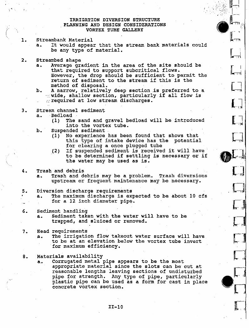
Streambank Materiala. It would appear that the stream bank materials could
be any type of material.
Streambed shapea. Average gradient in the area of the site should be
that required to support subcritical flows.However, the drop should be sufficient to permit thereturn of sediment to the stream if this is themethod of disposal.
b. A narrow, relatively deep section is preferred to a":':. wide, shallow section, particularly if all flow is;',:: required at low stream discharges.
Stream channel sedimenta. Bedload
(1) The sand and gravel bedload will be introducedinto the vortex tube.
b. Suspended sediment(1) No experience has been found that shows that
this type of intake device has the potentialfor clearing a once plugged tube
(2) If suspended sediment is received it will haveto be determined if settling is necessary or ifthe water may be used as is.
Trash and debrisa. Trash and debris may be a problem. Trash diversions
upstream or frequent maintenance may be necessary.
Diversion discharge requirementsa. The maximum discharge is expected to be about 10 cfs
for a 12 inch diameter pipe.
Sediment handlinga. Sediment taken with the water will have to be
trapped, and sluiced or removed.
Head requirementsa. The irrigation flow takeout water surface will have.
to be at an elevation below the vortex tube invertfor maximum efficiency.
Materials availabilitya. Corrugated metal pipe appears to be the most
appropriate material since the slots can be cut atreasonable lengths leaving sections of undisturbedpipe for strength. Any type of pipe, particularlyplastic pipe can be used as a form for cast in placeconcrete vortex section.
11-10
I~
•... ~ .... \I~I."/
~ I ; ,
",.,~.~.," ~._......
II~-m
IlJf\Il~---m
[J
I-Jl[J,[J
•
..:1 . r:~_Il,!.! ::~~ n4t\
. .
!(~.J
L:J:L-,]
r:;1[~u
n~- III
CJe[1It Ii
L
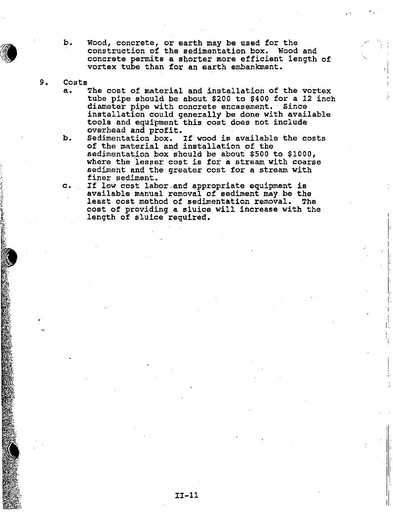
b. Wood, concrete, or earth may be used for theconstruction of the sedimentation box. Wood andconcrete permits a shorter more efficient length ofvortex tube than for an earth embankment.
, '
Ii
I I, !
9. Costsa. The cost of material and installation of the vortex
tube pipe should be about $200 to $400 for a 12 inchdiameter pipe with concrete encasement. Sinceinstallation eould generally be done with availabletools and equipment this cost does not includeoverhead and profit.
b. Sedimentation box. If wood is available the costsof the material and installation of thesedimenta~ion box should be about $500 to $1000,where the lesser cost is for a stream. with coarsesediment and the greater cost for a stream withfiner sediment.
c. If low cost labor,and appropriate equipment isavailable manual removal of sediment may. be theleast cost method of sedimentation removal. Thecost of providing a sluice will increase with thelength of sluice required.
II-II
I
1
·,I,
II
j,
:.,
I
!.III,
II·
IRRIGATION DIVERSION STRUCTUREDESIGN CRITERIA AND SPECIFICATIONS
VORTEX TUBE GALLERY
Design Criteria.
References:
1. Klingeman Peter C., Milhous Robert T., Oak Creek VortexBed-Load Sampler, Oregon State University, Corvalis,Oregon, 1970.
2. Mahmood Khalid, Flow Through Vortex Tube SedimentEjectors, ASCE Irrigation and Drainage Division SpecialtyConference, Logan Utah, August 13-15, 1975.
3. Melone A.M., Richardson E.V., Simons D.B., Exclusion andEjection of Sediment from Canals, Department of CivilEngineering, Colorado State University. Fort Collins,Colorado, April 1975.
4. Robertson A.R., Vortex Tube Sand Trap, Transaction ASCEVol. 127, Pt. III, 1962.
Specifications:
1. National Handbook of Conservation Practices, Dam,Diversion 348, Soil Conservation Service, WashingtonD.C., Oct. 1977.
11-12
IlUr~·
Irn~l
-IIWI[[--r],
\I[-rl:rL~]
il[~~l
il(~l.
IIr=r
IRRIGATION DIVERSION STRUCTUREVORTEX TUBE GALLERY
Vortex tube
'"---- Sediment box
Conal
/ II I
I I
TYPICAL SITE PLAN
FIGURE 1·
. 11-13
• 1
\ :.) :
I, I
~ : ii: i
: ,.1, I
. ii
:,fI
: ii
. IJ-mrn
/ ..IT:.(.1 i (:
It=r::
[~
rl:"! 'i 'I ,
,[ 1, IT'1l\]
[_.J'
'[-J
'IW
.~(
. IU1[::1;[i~li I -,: l~
Flowb ----
-....II.- _
streambed
_J _
, Vortex tube
..
11-14
PROFILE
FIGURE 2
v2
PLAN
d1Z2J-,....-J-------,. \0------...
IRRIGATION DIVERSION STRUCTUREI
VORTEX TUBE GALLERY
2:1 t
-s
v1
tZ]-' ---~;-1,,-.~d~--
--- --11--- ---
Vortex tube 1b1
.....,;--
••. '1,.
PLAN
2'-0" 3"
IRRIGATION DIVERSION·ibvSTRUCTU~'R"·.VORTEX TUBE GALLERY
"-0" 10'-0" oRen length
6"
Continuous slot
Sic
Band
PROFILE
, 2" dia. CMP
Cap
Encasement
CROSS SECTIONS
ALTERNATE 1
FIGURE 3
ALTERNATE 2
II-IS
. ~f,lll
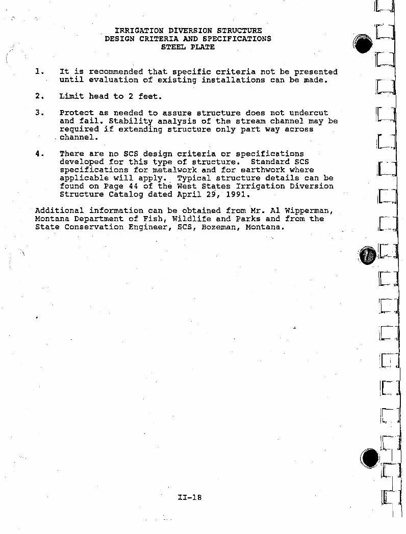
IRRIGATION DIVERSION STRUCTURESTEEL PLATE
Steel plate structures will be most applicable for thefollowing conditions:
1. Low flow conditions where limited checking is needed toaccomplish diversion of water.
2. Locations where flow conditions and access permittemporary installation and removal. Some attempts atmodifying the structure for permanent installation arebeing made.
3. Locations where streambed material size is fine enough topermit relatively easy installation. Large cobble orboulders in the streambed would require special sitepreparation and installation methodology.
4. Structures should be limited to checking of two feet orless.
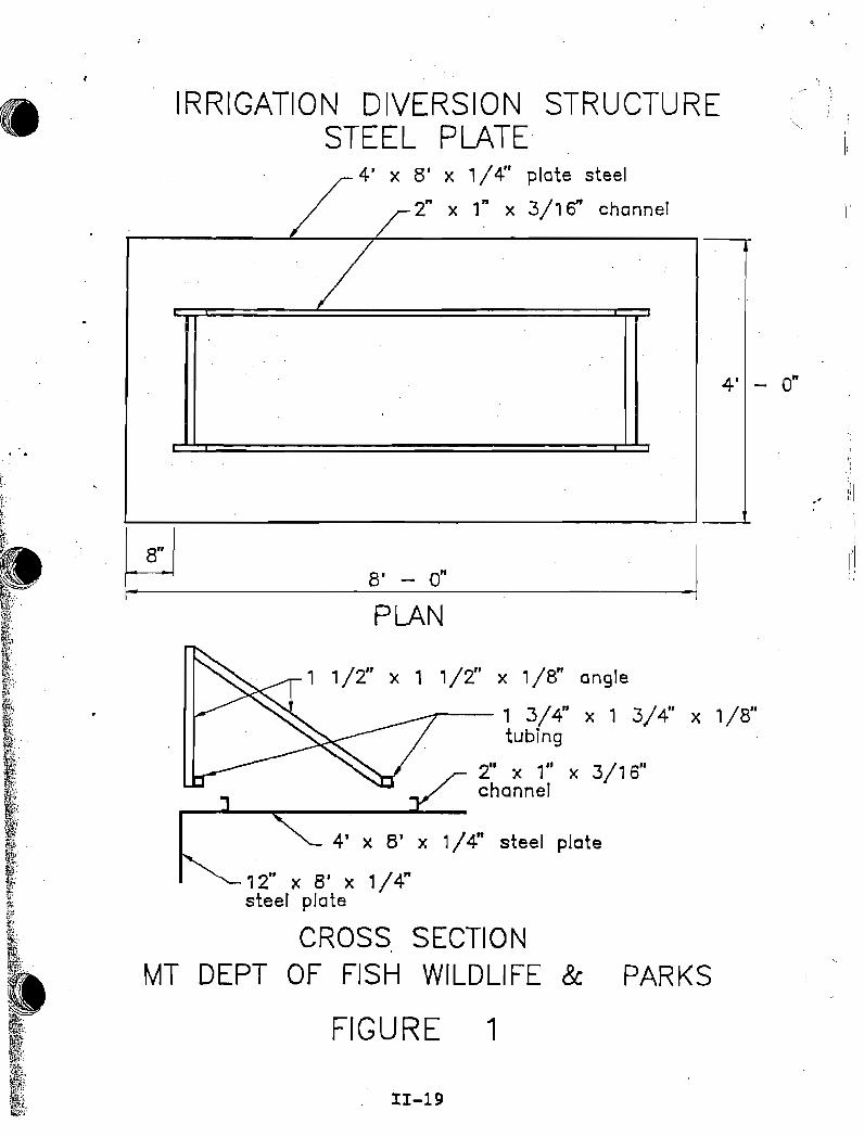
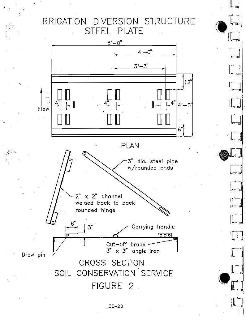
This' concept was developed as an alternative diversionstructure by the Montana Department of Fish, Wildlife, andParks. It consists of a-4' x B' x 1/4" steel plate with a 12inch vertical steel plate cutoff on the upstream side. Aseries of these B foot long plates are placed end to endacross the stream channel. These structures are normallytemporary structures placed in the stream in the summer andtaken out in the Fall. They permit checking of the waterusing collapsible flashboard guides and flashboards. Severalof these installations have been made in Montana which willev.entually permit evaluation of parameters for their use. SeeFigure No. 1 for details of the structure. The SoilConservation Service has suggested a modified but similarstructure to this. It has cutoffs on both upstream anddownstream sides and is being proposed for permanentinstallation in some sites. See Figure No.2 for details ofthis modified structure.
With several of these installations in place, furtherevaluation of the site and their performance will be possibleand should be undertaken. This would provide a goodevaluation of design criteria.
11-16
I~- lw
•'l1
<, 'IUrWIlr' 'j1'l..rr---mJ
i[' l! '1'"'IIDl
iI'l\\~
i,["ltI 'lIP!
IC~
itJI
(:J
lC~
lC.J1m", I
i i n :'lI,)l!1
'rILr,: J
1['. \ :I .' I I~'.
.•...1_,;,1( .
\.,... \ 1•. .f
I.'-:'1
I~"
1.
IRRIGATION DIVERSION STRUCTURESPLANNING AND DESIGN CONSIDERATIONS
STEEL PLATE
Streambed Materiala. Best adapted to sand and gravel streambeds.b. Finer grained more erodible materials may need rock
protection or deeper cutoffs.c. Cobble or boulder streambeds will require special
installation methods.
'.,
)
'I';')
2. Head Limitations - It is recommended that the maximumchecked head be less than two feet.
3.
4.
5.
Generally intended to be placed in the stream during lowflow conditions. This ,structure. may not be applicable andmay be unstable during high flow conditions. It shouldgenerally be removed in the Fall so that it is not in thestream during high Spring runoff.
Installation - Relatively easy to install. Anycontractor and many landowners would have equipment toinstall the plates. As presently·· used requires equipmentin the streambed twicep~r year.
Checking of water will be accomplished by placing woodboards to the elevation needed. Checking should belimited to two feet in most cases.
6. Stability of the chann~l may need to be evaluated when~sing this type of structure. This is especially truewhen using as a wing deflector part way across the streamas opposed to a structure extending across the entireriver.
7. Bank stability on the abutments should be addressed.Rock riprap of the abutments may be required.
8. Cost: $200.00 - $350.00 per 8 foot section. ($25.00$45.00 per square foot.)
II-17
IC,I'"
le,
iel[.'E.i[C',u
le,:l~'1~ 'I
lL,:lr- I
), - . :
'I,k-.J
_Ie:lL"IL~,
IL"I ,
\[--:"
IRRIGATION DIVERSION STRUCTURESTEEL PLATE
4' x 8' x , /4" plate steel
/ /2" x ," x 3/16" channel
/4' - 0"
it',;
JI'rl
I,If,I,
I"~
.' :i\,!
!,.\
i ~
I~
:,}
~ ;::1
:,1,.
j"
, 1/2" x 1 1/ z" x 1/8" on9Ie
.---, 3/4" x 1 3/4" x 1/8"tubing
2" x 1" x 3/1 6"channel
8' - 0"
PLAN
11-19
4' x 8' x 1/4" steel plate
12" x 8' x 1/4"steel plate
CROSS SECTIONMT DEPT OF FISH WILDLIFE & PARKS
FIGURE 1
[~.
Lr :'1ID!\
Ihl
UILJ
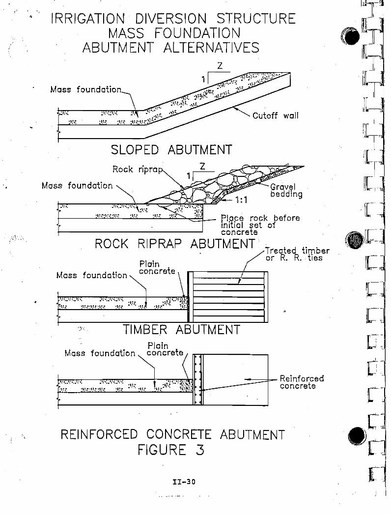
IRRIGATION DIVERSION STRUCTUREMASS FOUNDATION AND CHECK
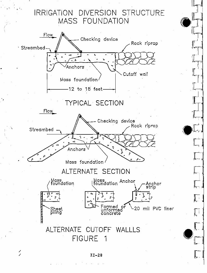
A mass foundation and check diversion structure is used whereit is necessary to raise the water surface in a waterway orstream, in order to divert all or part of the water to adifferent watercourse or irrigation canal. This type ofstructure consist of two major component parts. The checkcomponent consists of devices such as jacks, which temporarilyraise and regulate the water level at the desired elevation.These check devices are discussed in more detail elsewhere inthis report. The mass foundation is the permanent componentof the structure that supports and anchors the checks and. alsomay act to stabilize the channel at the point of diversion.The crest of the mass foundation is usually placed at or nearthe flow line of the channel. It must be constructed of aerosion resistant material and provide the required cutoff,length, height, bulk, etc. necessary to meet the design lifeof the structure. The mass 'foundation is the most costlycomponent of the structure.
Reinforced concrete or treated timber have typically been usedto construct the foundation component of this type ofdiversion structure. This concept consists of constructingthe foundation as a mass utilizing locally available materials
. and/or construction methods not typically used for this typeof structure such as: Roller ~ompacted Concrete, Nonreinforced Concrete, Grouted Rock Riprap, Soil Cement or LooseRock. A more detailed description of each of thesealternatives follows and typical sketches are shown in figure1.
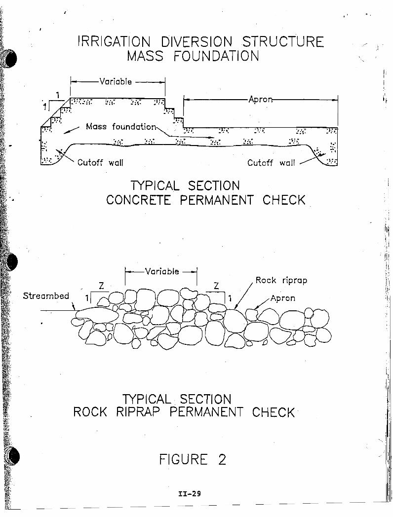
These same materials could be used in the construction ofpermanent check diversion structures as shown in figure 2 orcombination of permanent and temporary check diversion!>tructures. The temporary check diversion is generallyconsidered the most desirable due to the fact that it tends tominimize the permanent effects of the diversion on the streamand fisheries. Channel hydraulics and owners desires mayrequire the consideration of a combination permanent andtemporary diversion structure. The combination diversionstructure may be constructed by installing a permanent crestelevated above the channel bottom across the entire channelwith check devices anchored to this permanent crest to furtherraise the water surface temporarily or a portion of the widthof the diversion could be constructed with a permanent crestwith check devices at channel bottom and the remainder of thewidth stair stepped up with a permanent crest.
Sketches of alternative methods of constructing the abutmentsare shown in figure 3.
11-21
Ii'II,".11
::::
....
iii
"- I:1,
II
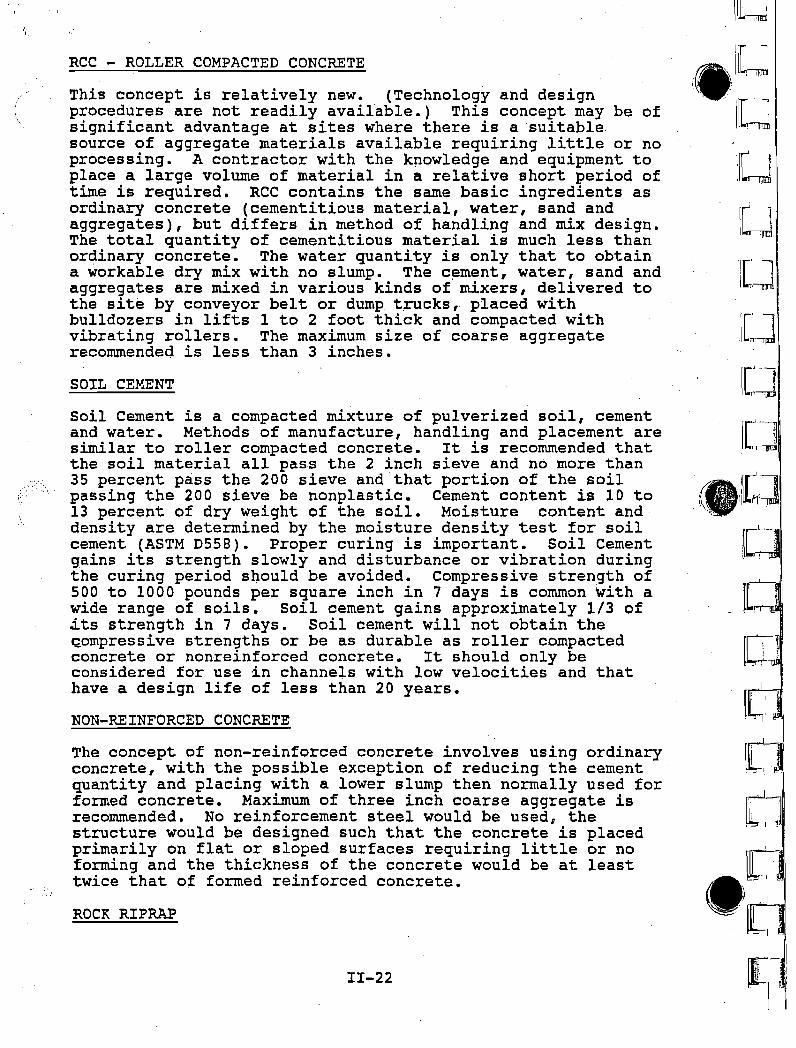
RCC - ROLLER COMPACTED CONCRETE
This concept is relatively new. (Technology and designprocedures are not readily available.) This concept may be ofsignificant advantage at sites where there is a suitablesource of aggregate materials available requiring little or noprocessing. A contractor with the kpowledge and equipment toplace a large volume of material in a relative short period oftime is required. RCC contains the same basic ingredients asordinary concrete (cementitious material, water, sand andaggregates), but differs in method of handling and mix design.The total quantity of cementitious material is much less thanordinary concrete. The water quantity is only that to obtaina workable dry mix with no slump. The c~ment, water, sand andaggregates are mixed in various kinds of mixers, delivered tothe site by conveyor belt or dump t.rucks, placed withbulldozers in lifts 1 to 2 foot thick and compacted withvibrating rollers. The maximum size of coarse aggregaterecommended is less than 3 inches.
SOIL CEMENT
Ctl-\ ..
Soil Cement is a compacted mixture of pulverized soil, cementand water. Methods of manufacture, handling and placement aresimilar to roller compacted concrete. It is recommended thatthe soil material all pass the 2 inch sieve and n6 more than35 percent pass the 200 sieve and that portion of the soilpassing the 200 sieve be nonplastic. Cement content is 10 to13 percent of dry weight of the soil. Moisture content anddensity are determined by the moisture density test for soilcement (ASTM D558). Proper curing is important. Soil Cementgains its strength slowly and disturbance or vibration duringthe curing period s~ould be avoided. Compressive strength of500 to 1000 pounds per square inch in 7 days is common with awide range of soils. Soil cement gains approximately 1/3 of~ts strength in 7 days. Soil cement will not obtain the~ompressive strengths or be as durable as roller compactedconcrete or nonreinforced concrete. It should only beconsidered for use in channels with low velocities and thathave a design life of less than 20 years.
The concept of non-reinforced concrete involves using ordinaryconcrete, with the possible exception of reducing the cementquantity and placing with a lowe~ slump then normally used forformed concrete. Maximum of three inch coarse aggregate isrecommended. No reinforcement steel would be used, thestructure would be designed such that the concrete is placedprimarily on flat or sloped surfaces requiring little or noforming and the thickness of the concrete would be at leasttwice that of formed reinforced concrete.
1I-22
NON-REINFORCED CONCRETE
ROCK RIPRAP
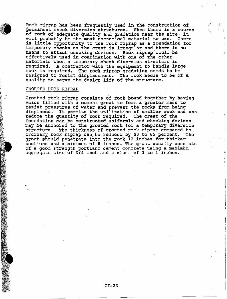
~ock riprap has been frequently used in the construction ofpermanent check diversion structures. When there is a sourceof rock of adequate quality and gradation near the site, itwill probably be the most economical material to use. Thereis little opportunity to use rock riprap as a foundation fortemporary checks as the crest is irregular and there is nomeans to attachehecking devices. Rock riprap'could beeff~ctively used in combination with one of the othermaterials when a temporary check diversion structure isrequired. A contractor with the equipment to handle largerock is required. The rock riprap.gradation needs to.bedesigned to resist displacement. The rock needs to be of aquality to serve the design life of the structure.
GROUTED ROCK RIPRAP
Grouted rock riprap consists of rock bound together by havingvoids filled with a cement grout to form a greater mass toresist pressures of water and prevent the rocks from beingdisplaced. It permits the utilization of smaller rock and canreduce the quantity of rock required. The crest of thefoundation can be constructed u~iformly and checking devicesmay be anchored to the grouted rock for a temporary diversionstructure. The thickness of grouted rock riprap compared toordinary rock riprap can. be reduced by 50 to 65 percent. The
'grout should penetrate into the rock 12 inches for thickersections and a minimum of 8 inches. The grout usually consistsof a good strength portland cement C0~crete using a maximumaggregate size of 3/4 inch and aslur-.: of 3 to 4 inches.
II-23
I .
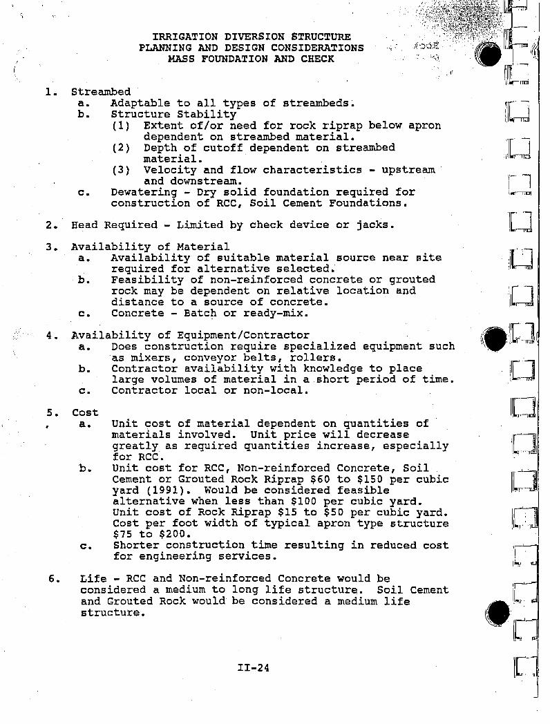
IRRIGATION DIVERSION STRUCTUREPLANNING AND DESIGN CONSIDERATIONS
MASS FOUNDATION AND CHECK"";.' .
1. Streambeda. Adaptable to all types of streambeds~
b. Structure Stability(1) Extent of/or need for rock riprap below apron
dependent on streambed material.(2) Depth of cutoff dependent on streambed
material.(3) Velocity and flow characteristics - upstream
and downstream.c. Dewatering - Dry solid foundation required for
construction of RCC, Soil Cement Foundations.
2. Head Required - Limited by check device or jacks.
.:~ .I, ~!
\Ie]
.IL]:[~J.I . \
IlL:]itC]lll~
Life - RCC and Non-reinforced Concrete would beconsidered a medium to long life structure. Soil Cementand Grouted Rock would be considered a medium lifestructure.
11-24
Costa. Unit cost of material dependent on quantities of
materials involved. unit price will decreasegreatly. as required quantities increase, especiallyfor RCC.
b. unit cost for RCC, Non-reinforced Concrete, SoilCement or Grouted Rock Riprap $60 to $150 per cubicyard (1991). Would be considered feasiblealternative when less than $100 per cubic yard.unit cost of Rock Riprap $15 to $50 per cubic yard.Cost per foot width of typical apron type structure$75 to $200.
c. Shorter construction time resulting in reduced costfor engineering services.
Availability of Equipment/Contractora. Does construction require specialized equipment such
as mixers, conveyor belts, rollers.b. Contractor availability with knowledge to place
large volumes of material in a short period of time.c. Contractor local or non-local.
Availability of Materiala. Availability of suitable material source near site
required for alternative selected.b. Feasibility of non-reinforced concrete or grouted
rock may be dependent on relative location anddistance to a source of concrete.
c. Concrete - Batc~ or ready-mix.
6.
5.
4.
3.
7. Construction Time - Actual time required for constructionwould be considerably less than other types ofconstruction such as formed reinforced concrete.
11-25
IRRIGATION DIVERSION STRUCTUREDESIGN CRITERIA AND SPECIFICATIONS
MASS FOUNDATION AND CHECK
Design criter~a and specifications are available for each ofthe alternative concepts for mass foundation diversionstructures. Some of these references are as follows:
1. Soil Conservation Service, Engineering Design Standards Far West States, West National Technical Center,Portland, Oregon, 1970.
2. Soil Conservation Service, Drop Spillways NEB Section 11,Soil Conservation Service, Washington D.C.
3. Soil Conservation Service, Specifications forConstruction Contracts NEB Section 20: Specification 61 Loose Rock Riprap; Specification 62 - Grouted RockRiprap, Soil Conservation Service, Washington D.C.
4. Design of Small Dams, Third Edition, USDI - Bureau ofReclamation
5. Specifications for Structural Concrete for Buildings (ACI301-84), American C~ncrete Institute, Detroit, Michigan
6. Bank and Shore Protection in California Highway Practice,State of California, Department of Public Works, Divisionof Highways, Sacramento, California
7. West States Irrigation Diversion Structure Catalog, SoilConservation Service, West National Technical Center,Portland, Oregon.
~. Portland Cement Association, Soil Cement SlopeConstruction Handbook EB003.09s, Portland CementAssociation, Skokie Illinois, 1979
9. Portland Cement Association, Soil Cement Slope Protectionfor Embankments: Planning and Design, IS173.02W,Portland Cement Association, Skokie Illinois, 1975
10. REC-ERC-7I-20 "Soil Cement Slope Protection on Bureau ofReclamation Features, USDI, BureaU of Reclamation,Denver, Colorado, 1971
11 •. REC-ERC-B4-IS "Mix Design Investigation-Roller CompactedConcrete Construction-Upper Stillwater Dam, Utah, USDI,Bureau of Reclamation, 1984
12. REC-ERC-B4-2S "Performance of Soil Cement Dam Facings 20 - year Report, 1984
II-26
•..... :D
.! \
'1- '1[.I' , I
~ ~ I
13. ACER Technical Memorandum No. B Guidelines for Designingand Constructing Roller-Compacted Concrete Dams, USDIBureau of Reclamation', Denver, Colorado, 1987
"T'"T' ." ..
,, '
20 mil PVC liner
Mass . Anchorfoundation
~- Checking deviceRock riprap
~- Checking device
Mass foundation
TfPICAL SECTION
ALTERNATE SECTIONMassd t"faun a Ion
Sh1eetpi mg
ALTERNATE CUTOFF WALLLSFIGURE 1
11-28
Flow..
Flow..
IRRIGATION DIVERSION STRUCTUREMASS FOUNDATION
streambed
//
. streambed
,~"
o ,
IRRIGATION DIVERSION STRUCTUREMASS FOUNDATION
,I
h
Cutoff wall
., ... :~.-., ..-: (.
------APront-----1
Cutoff wall
•
TYPICA,L SECTIONCONCRETE PERMANENT CHECK
II-29
,,/ !
1 '
II'
Rock riprap
FIGURE 2
,Variablei
TYPICAL, SECTIONROCK RIPRAP PERMANENT CHECK'
Streambed
"I][~'l
e,'r- i
~'C,~ ilLr-· ,~
I[:rliL:[
1 ~,-
i r 'ij
----='=-- Reinforcedconcrete
~~~""""Gravelbedding
PlainconcreteMass foundation
REINFORCED CONCRETE ABUTMENTFIGURE 3
TIMBER ABUTMENT
SLOPED ABUTMENT
..".r----:;o:...:....;...:~~-~...:..:.:....~~_place rock before
mitial set ofconcrete
ROCK RIPRAP ABUTMENT Treated timberrR. R. ties
Plain ~oMass foundation concrete \ I,
:'.. :'.. :'. . : '.. : '.... '. ':"~''':W"I" .Hr~l~~,. -:i=:.,:: .',: ...,~:~ .'.:~ .,:~.:', .,.:,
Mass foundation
Mass foundation
I,I "'t
IRRIGATION DIVERSION STRUCTUREMASS FOLINDATION
ABUTMENT ALTERNATIVES
II-3D[,~ -
, ..
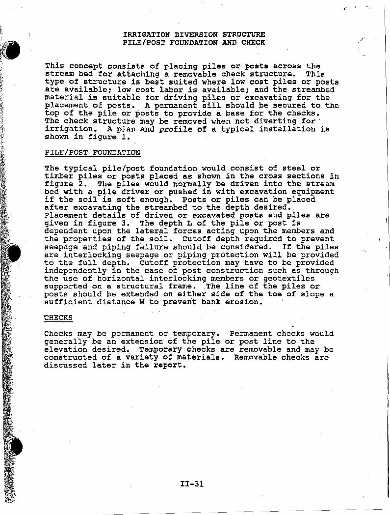
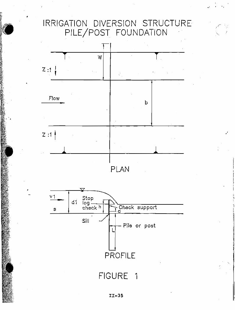
IRRIGATION DIVERSION STRUCTUREPILE/POST FOUNDATION AND CHECK
This concept consists of placing piles or posts across thestream bed for attaching a removable check structure. Thistype of structure is best suited where low cost piles or postsare available; l~w cost labor is available; and the streambedmaterial is suitable for driving piles or excavating for theplacement of posts. A permanent sill should be secured to thetop of the pile or posts to provide a base £or the checks.The check structure may be removed when not diverting for .irrigation. A plan and profile of a typical installation isshown in figure 1.
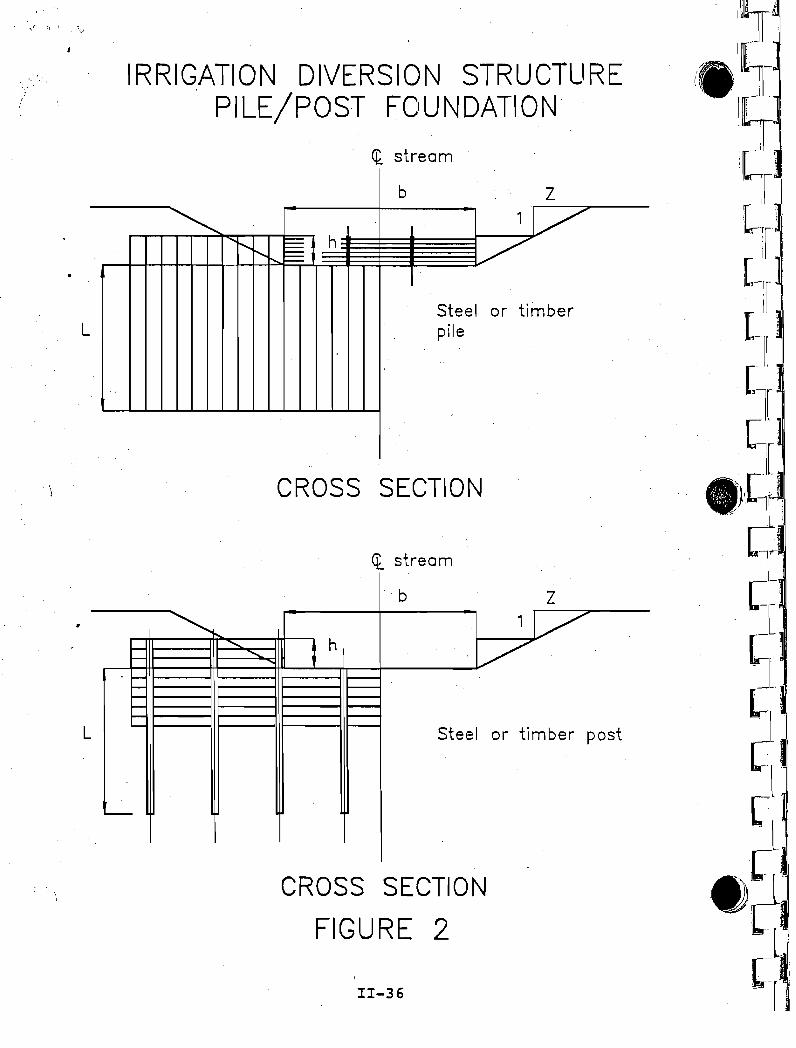
PILE/POST FOUNDATION
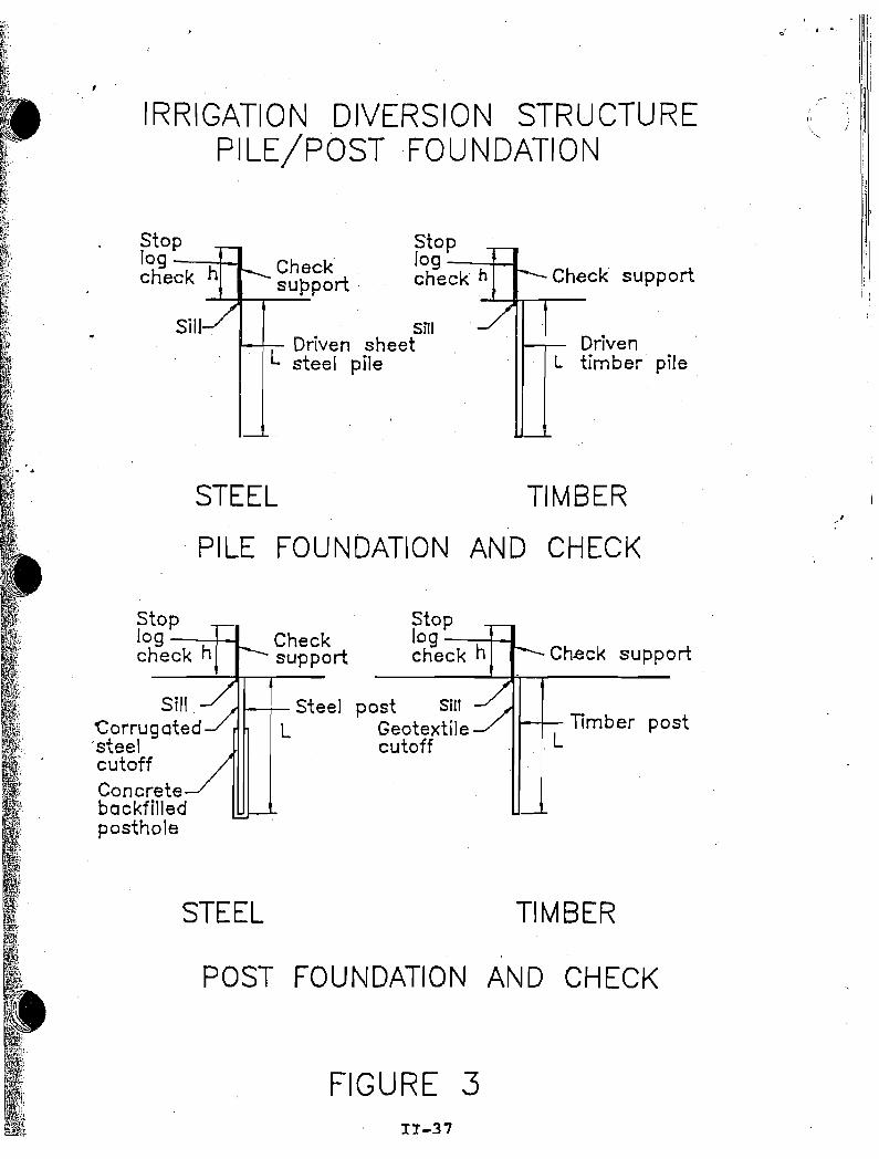
The typical pile/post foundation would consist of steel ortimber piles or posts placed as shown in the cross sections infigure 2. The piles would normally be driven into the streambed with a pile driver or pushed in with excavation equipmentif the soil is soft enough. Posts or piles can be placedafter excavating the streambed to the depth desired.Placement details of driven or excavated posts and piles aregiven in figure 3. The depth L of the pile or post isdependent upon the later~l forces acting upon the members andthe properties of the soil. Cutoff depth required to preventseepage and piping failure should be considered. If the pilesare interlocking seepage or piping protection will be providedto the full depth. Cu~off protection may have to be providedindependently in the case of post construction such as .throughthe use of horizontal interlocking members or geotextilessupported on a structural frame. .The line of the piles orposts should be extended on either side of the toe of slope asufficient distance W to prevent bank erosion.
CHECKS
Checks ~ay be permanent or·temporary. Permanent checks wouldgenerally be an extension of the pile or post line to theelevation desired. Temporary checks are removable and may beconstructed of a variety of materials. Removable checks arediscussed later in the report.
11-31
II
"1.
2.
3.
4.
5.
6.
-7.
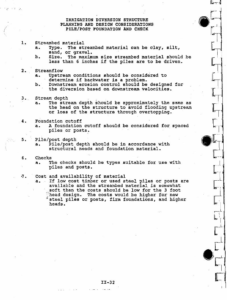
IRRIGATION DIVERSION STRUCTUREPLANNING AND DESIGN CONSIDERATIONS
PILE/POST FOUNDATION AND CHECK
Streambed materiala. Type. The streambed material can be clay, silt,
sand, or gravel.b. Size. The maximum size streambed material should be
less than 6 inches if the piles are to be driven.
Streamflowa. Upstream conditions should be considered to
determine if backwater is a problem.b. Downstream erosion control should be designed for
the diversion based on downstream velocities.
Stream depth .a. The stream depth should be approximately the same as
the head on the structure to avoid flooding upstreamor loss of the structure through overtopping.
Foundation cutoffa. A foundation cutoff should be considered for. spaced
piles or posts ,.
Pile/post ,deptha. Pile/post depth should be in accordance with
structural needs and foundation material.
Checksa. The checks should be types suitable for use with
piles and posts.
Cost and availability of materiala. If low cost timber or used steel piles or posts are
available and the streambed material. is somewhatsoft then the costs should be low for the 3 foot
:head design. The costs would be higher for new:/), steel piles or posts, firm foundations, and higher
heads.
II-32
~.IlL.'IC I
I~I[T
5·)2
~.C
l[;lDl
,'[--
: 1
~\
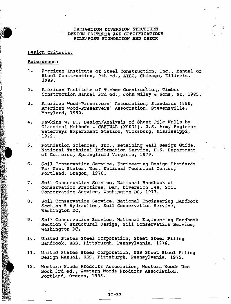
IRRIGATION DIVERSION STRUCTUREDESIGN CRITERIA AND SPECIFICATIONS
PILE/POST FOUNDATION AND CHECK
Design Criteria.
References:
1. American Institute of Steel Construction, Inc., Manual ofSteel Construction, 9th ed~, AISC, Chicago, Illinois,1989.
20 American Institute of Timber Constructio~, TimberConstruction Manual 3rd ed., John Wiley & Sons, NY, 1985.
3. American Wood-Preservers' Association, Standards 1990,American Wood-Preservers' Association, Stevensville,Maryland, 1990.
4. Dawkins Wo Po, Design/Analysis of Sheet Pile Walls byClassical Methods - CSHTWAL (X0031), u.s. Army EngineerWaterways Experiment Station, Vicksburg, Mississippi,1979.
5. Foundation Sciences, Inc., Retaining Wall Design Guide,National Technical Information Service, u.S. Departmentof Commerce, Springfield Virginia, 1979.
6. Soil Conservation Service, Engineering Design StandardsFar West States, West National Technical Center,Portland, Oregon, 1970.
7. Soil Conservation Service, National Handbook ofConservation Practices, Darn, Diversion 348, SoilConservation Service, Washington DC, 1977.
80 Soil Conservation Service, National Engineering Handbooksection 5 Hydraulics, Soil Conservation Service,Washington DC,
90 Soil Conservation Service, National Engineering HandbookSection 6 Structural Design, Soil Conservation Service,Washington DC,
10. united States Steel Corporation, Sheet Steel PilingHandbook, USS, Pittsburgh, Pennsylvania, 1976.
11. United States Steel Corporation, USS Sheet Steel PilingDesign Manual, USS, Pittsburgh, Pennsylvania, 1975.
12. Western Woods Products Association, Western Woods UseBook 3rd ed., Western Woods Products Association,Portland, Oregon, 1983.
II~33
\,
1 r ,n 'l c:,
Specifications:
1. Soil Conservation Service, National Handbook ofConservation Practices, Dam, Diversion 348, SoilConservation Service, Washington DC, 1977.
2. Soil Conservation Service, National Engineering HandbookSection 20 Specifications for Construction Contracts,Soil Conservation Service, Washington DC,
3. Western Wood Preservers Institute, Guide to theCharacteristics, Use, and Specifications of PressureTreated Wood, Western Wood Preservers Institute,Vancouver, Washington, 1990.
,
:1:I-34
Illtl
• ..~L, IL
!\~1
11hIL~
IlL,11L~RI
\I[~rnl
.~~"C"~1
['I
[:i[:'-
L~'
L-.. ' '
,r.~
6..1
(1l
IRRIGATION DIVERSION STRUCTUREPILE/POS"T FOUNDATION
"'l'1 a -
."
,.
t--+- Pile or postL
PLAN
11-35
PROFILE
FIGURE 1
Sill
d1stopI09-~ """'=":---:--_----;- _
check h Check supporta
-s
v1
-.--
T w T
1 t -
Flow.. b
:1 t..
1 1
z
z:
. .
,t. ") \'.1
L
L
.. '.
IRRIGATION DIVERSION STRUCTURE. PILE/POST FOUNDATION
- ct stream
b Z
~ '1/" ........ ~~ h /'I'-.r-...1::::::""1
Steel or timberpile
CROSS SECTION
ct stream
b z'1/
.......~ h ./........
Steel or timber post
'---
CROSS SECTION
FIGURE 2
1I-36
· , .
IRRIGATION DIVERSION STRUCTUREPILE/POST FOUNDATION
-: i I
-or #. or I;
i!
iiCheck support
1--1-- DrivenL timber pile
stoplog ---+--I
check h
smL Driven sheet
steel pile
Checksupport· .
......I--.JI--T------
Sill
Stoplog ---+-I
check h
STEEL TIMBER
PILE FOUNDATION AND CHECK
Ch.eck support
t--t--- Timber post.L
TIMBER
Stoplog --t-I
check hChecksupport
f---+- steel post SillL Geotextile
cutoff
STEEL
stoplog ---+--I
check h
Sill .'Corrugated'steelcutoffConcretebackfilledposthole
POST FOUNDATION AND CHECK
FIGURE 311-37
l' .
IRRIGATION DIVERSION STRUCTUREPUMP
INTRODUCTION
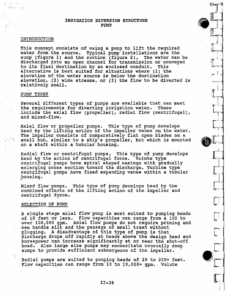
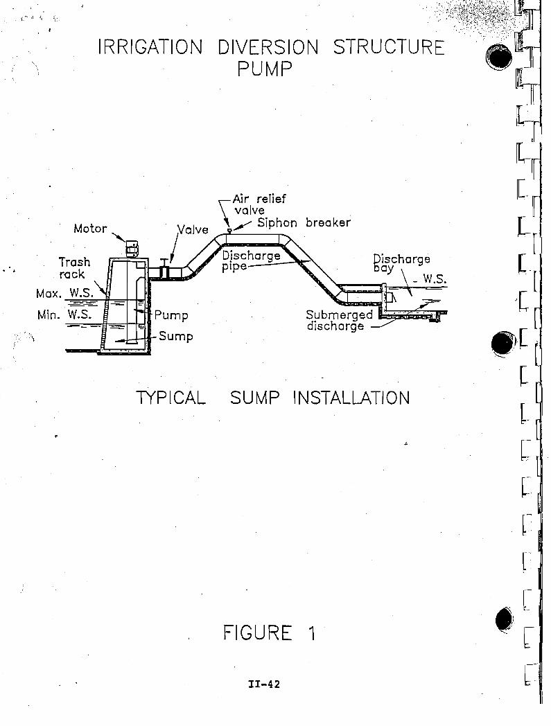
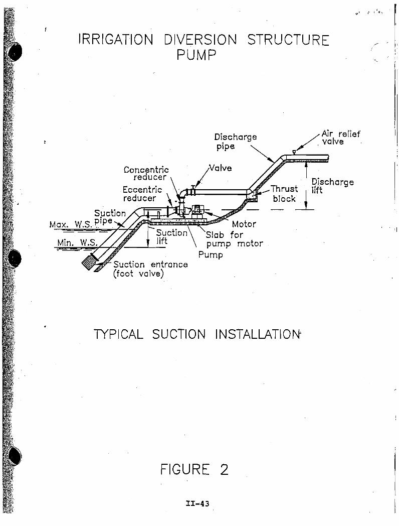
This concept consists of using a pump to lift the requiredwater from the source. Typical pump installations are thesump (figure 1) and the suction (figure 2). The water can bedischarged into an open channel for transmission or conveyedto its final destination by an enclosed conduit. Thisalternative is best suited for situations where (1) theelevation of the water source is below the destinationelevation, (2) wide streams, or (3) the flow to be diverted isrelatively small.
PUMP TYPES
Several different types of pumps are available that can meetthe requirements for diverting irrigation water. Theseinclude the axial flow (propeller), radial flow (centrifugal),and mixed-flow.
Axial flow or propeller pumps. This type of pump developshead by the lifting action of the impeller vanes on the water.The impeller consists of" comparatively flat open blades on asmall hub, similar .to a ship's propeller, but which is mountedon a shaft within a tubular housing.
Radial flow or centrifugal pumps. This type of pump developshead by the action of centrifugal force. Volute typecentrifugal pumps have spiral shaped casings with graduallyenlarging cross section toward the discharge. Turbine typecentrifugal pumps have fixed expanding vanes within a tubularhousing ••
Mixed flow pumps. This type of pump develops head by thecombined effects of the lifting action of the impeller andcentrifugal f~rce.
SELECTION OF PUMP
A single stage axial flow pump is most suited to pumping headsof 10 feet or less. Flow capacities can range from a 100 toover 100,000 gpm. Axial flow pumps do not require priming andcan handle silt and the passage of small trash withoutplugging. A disadvantage of this type of pump is thatdischarge drops off rapidly at heads above the .design head andhorsepower can increase significantly at or near the shut-offhead. Also large size pumps may necessitate unusually deepsumps to provide sufficient submergence of the impeller.
Radial pumps are suited to pumping heads of 20 to 200+ feet.Flow capacities can range from 10 to 10,000+gpm. Volute
11-38
IlljlII ..-J1.11
'- 11r",_11'1I' ,Ill,' " '
centrifugal pumps are limited to locations'where the suctionlift is less than 20 feet. Centrifugal pumps must be primedbefore the pump will operate. Turbine pump installationsrequire a sump.
Mixed flow pumps are suited to pumping heads of 10 to 90 feet.Flow capacities can range from 1,000 to 100,000+ gpm.
Multiple stage pumps are used when sufficient head cannot bedeveloped efficiently in one stage. These pumps have two ormore impellers operating in series; that is, the discharge ofone impeller is connected to the suction of the next impeller.propeller pumps are normally single stage.
11-39
,Q r ,~, ~ ,
.,i
1.
2.
3.
4.
5.
6.
7 •.
IRRIGATION DIVERSION STRUCTUREPLANNING AND DESIGN CONSIDERATIONS
PUMP
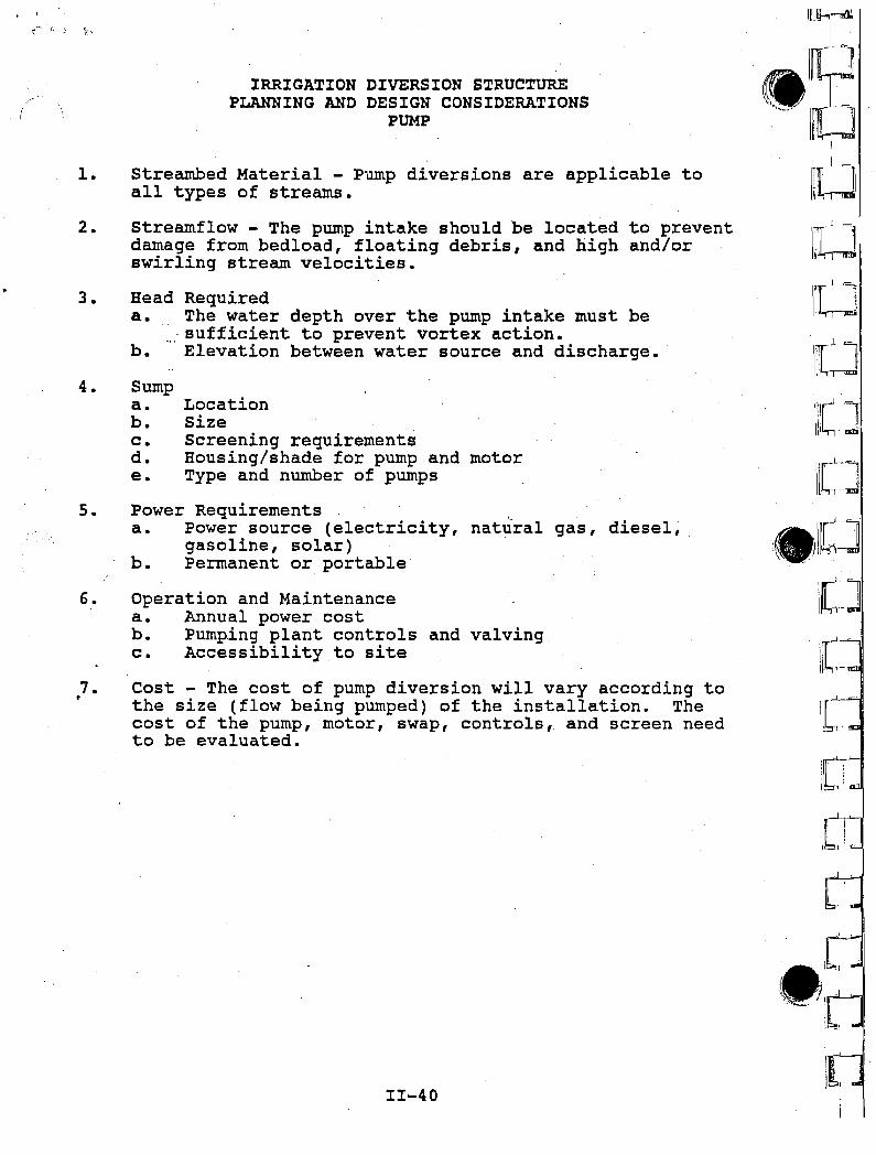
Streambed Material - Pump diversions are applicable toall types of streams.
Streamflow - The pump intake should be located to preventdamage from bedload, floating debris, and high and/orswirling stream velocities.
Head Requireda., The water depth over the pump intake must be
.,:. sufficient to prevent vortex action.b. Elevation between water source and discharge.
Sumpa. Locationb. Sizec. Screening requirementsd. Housing/shade for pump and motore. Type and number of pumps
Power Requirementsa. Power source (electricity, natural gas, diesel;
gasoline, solar)b. Permanent or portable
Operation and Maintenancea. Annual power costb. Pumping plant controls and valvingc. Accessibility to site
Cost - The cost of pump diversion will vary according tothe size (flow being pumped) of the installation. Thecost of the pump, motor, swap, controls, and screen needto be evaluated.
11-40
lII·rI~~
.,,-'J~I~
J_
I~W"~11
IwII~l
liI:J\rr-J lJlI!,-,..J
IllO
.I'Ji\(~J
•
11
~" .",-.- '. /1
I(
IRRIGATION DIVERSION STRUCTUREDESIGN CRI~ERIA AND SPECIFICATIONS
PUMP
General
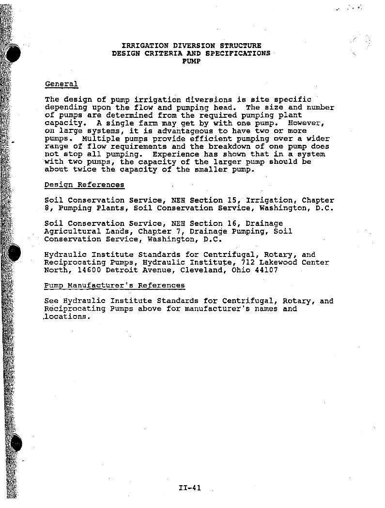
The design of pump irrigation diversions is site specificdepending upon the flow and pumping head. The size and numberof pumps are determined from the required pumping plantcapacity. A single farm may get by with one pump.. However,on large systems, it is advantageous to have two or morepumps. MUltiple pumps provide efficient pumping over a widerrange of flow requirements and the breakdown of one pump doesnot stop all pumping. Experience has shown that in a systemwith two pumps, the capacity of the larger pump should beabout twice the capacity of the smaller pump.
Design References
Soil Conservation Service, NEB Section 15, Irrigation, ChapterS, Pumping Plants, Soil Conservation Service, Washington, D.C.
Soil Conservation Service, NEB Section 16, DrainageAgricultural Lanos ,Chap_ter 7, Drainage Pumping, SoilConservation Service, Washington, D.C.
Hydraulic Institute Standards for Centrifugal, Rotary, andReciprocating Pumps, HydraUlic Institute, 712 Lakewood CenterNorth, 14600 Detroit Avenue, Cleveland, Ohio 44107
Pump Manufacturer's References
See Hydraulic Institute Standards for Centrifugal, Rotary, andReciprocating Pumps above for manufacturer's names and.locations.
11-41
<:,,' ,G 0::,
, I
IRRIGATION DIVERSION\ PUMP
. ,'. ,.',.
1YPICAL SUMP INSTALLATION
DischargeDay
- W.S.
'\
Air reliefvalve
Valve ,,/" Siphon breaker
I DjschargeI---or.----". pIpe--=::.---~"Trash
rock
Max. W.S.
Min. W.S. Pump--- ~ "'=
~~Sump
FIGURE 1
11-42
11-43
'I
I,
/Air refief/ ,valve '
DischargeThrust.'I Ii1ftblock
i
Dischargepipe
MotorSlab forpump motor
Pump
Suctionlift
Suction entrance(foot valve)
FIGURE 2
TYPICAL SUCTION INSTALLATIO~
IRRIGATION DIVERSION STRUCTUREPUMP
Concentricreducer
Eccentricreducer
SuctionMax. W.S.~ipe
I
Appendix IIIChecks
ii,!I
I!I i
111-1
Costs:
References:
")
Soil Conservation Service, National Engineering HandbookSection 6 Structural Design, Soil Conservation Service,Washington D.C.
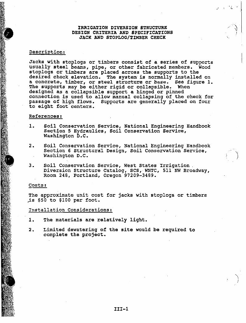
Description:
IRRIGATION DIVERSION STRUCTUREDESIGN CRITERIA'AND SPECIFICATIONS
JACK AND STOPLOG/TIMBER CHECK
Jacks with stoplogs or timbers consist of a series of supportsusually steel beams, pipe, or other fabricated members. Woodstoplogs or timbers are placed across the supports to thedesired check elevation. The system is normally installed ona concrete, timber, or steel structure or base. See figure 1.The supports may be either rigid or collapsible. Whendesigned as a collapsible support a hinged or pinnedconnection is used to allow manual collapsing of the check forpassage of high flows. Supports are generally placed on fourto eight foot centers.
1. Soil Conservation Service, National Engineering HandbooksectionS Hydraulics, Soil Conservation Service,Washington D.C.
2.
1. The materials are relatively light.
2. Limited dewatering of the site would be required tocomplete the project.
3. Soil Conservation Service, West States Irrigation.Diversion Structure Catalog, SCS,WNTC, 511 NW Broadway,Room 248, Portland, Oregon 97209-3489.
Installation Considerations:
The approximate unit cost for jacks with stoplogs or timbers~s $50 to $100 per foot.
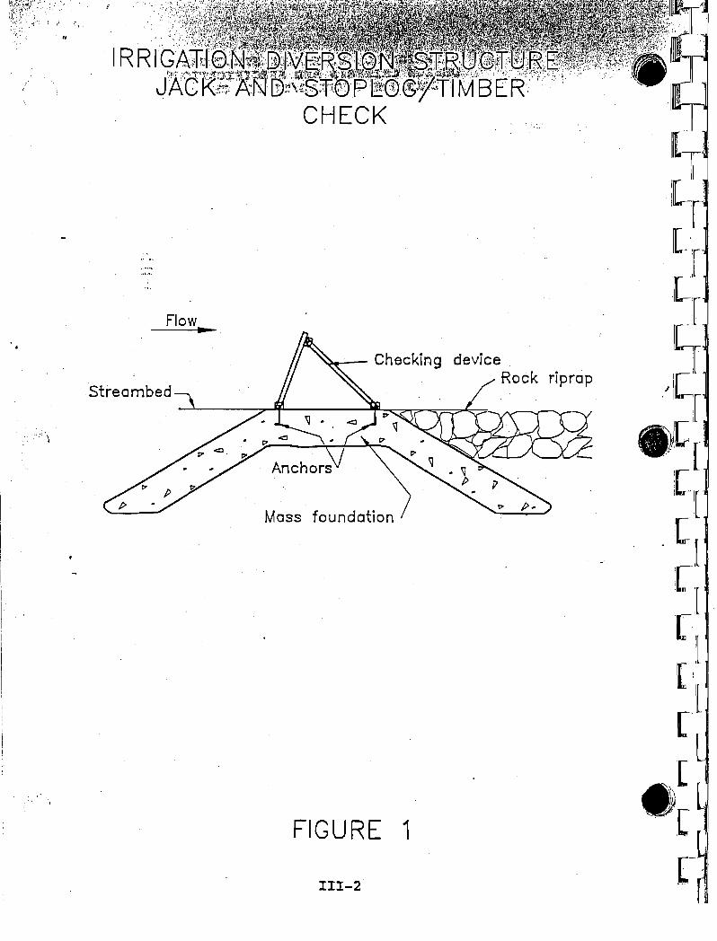
Flow..Streambed
~- Checking deviceRock riprap
Mass foundation
FIGURE 1
1II-2
IRRIGATION DIVERSION STRUCTUREDESIGN CRITERIA AND SPECIFICATIONS
INFLATABLE FABRIC CHECK
Description:
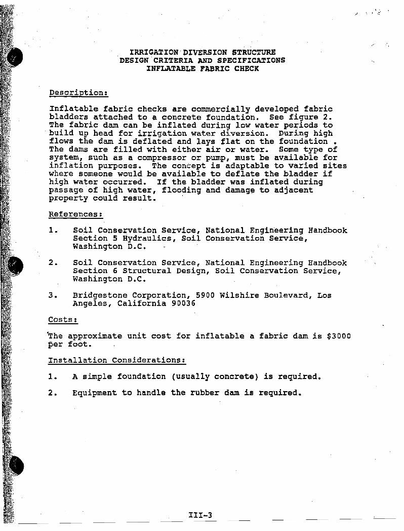
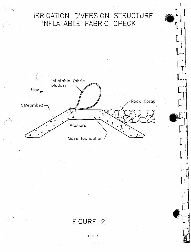
Inflatable fabric checks are commercially developed fabricbladders attached to a concrete foundation. See figure 2.The fabric dam can be inflated during low water pe~iods to
. build up head for irrigation water diversion. During highflows the dam is deflated and lays flat on the foundation •The damS are filled with either air or water. Some type ofsystem, such as a compressor or pump, must be av~ilable forinflation purposes. The concept is adaptable to varied siteswhere someone would be available to deflate the bladder ifhigh water occurred. If the bladder was inflated duringpassage of high water, flooding and damag~ to adjacentproperty could result. '
References:
1. Soil Conservation Service, National Engineering HandbookSection 5 Hydraulics, Soil Conservation Service,Washington D.C.
2. Soil Conservation Service, National Engineering HandbookSection 6 Structural Design, Soil Conservation Service,Washington D.C.
3. Bridgestone Corporation, 5900 Wilshire Boulevard, LosAngeles, California 90036
Costs:
The approximate unit cost for inflatable a fabric dam is $3000per foot.
Installation Considerations:
1. A simple foundation (usually concrete) is required.
2. Equipment to handle the rubber dam is required.
111-3
IRRIGATION DIVERSION STRUCTUREINFLATABLE FABRIC CHECK
1. 1 .
;.,~'"'; ( .1", ~~
., .
.'"...
Flow..
Inflatable fabricbladder -----"
Mass foundation
FIGURE 2
. I1I-4
IRRIGATION DIVERSION STRUCTUREDESIGN CRITERIA AND SPECIFICATIONS
LOG CHECK
Description:
A log check consists of using utility poles of tree logs asthe water checking device. See figure 3. The logs may spanall or a portion of the stream. The placement and removal ofthe logs will require equipment handling.
References.
1. Soil Conservation Service, National Engineering Handbook,Section 5 Hydraulics, Soil Conservation Service,Washington D.C.
2. Soil Conservation Service, Engineering Design Standards,Far West States, West National Technical Center, PortlandOregon, 1970.
3. American Society of Agricultural Engineers, EngineeringPractice 388.2 Design Properties of Round, Sawn, andLaminated Preserva~ivelyTreated Construction Poles andPosts, American Society of Agricultural Engineers, 2950Niles Road, st. Joseph, Michigan.
4. Timber Construction Manual, American Institute of TimberConstruction, Washington, D.C.
Costs:
The approximate unit costs for logs or poles will vary locallyas to availability of materials. Typical costs will be $5 to'$15 per foot.
Installation Considerations:
1. Requires foundation structure or erosion resistance innatural stream bottoms.
2. The ends of the logs must be tied into the banks or wallsof the foundation structure.
3. Equipment needs for lifting and placing logs or polesacross the stream and their subsequent removal.
4. Limit installation to sites where, minimal adjustment isneeded in the checked water depth through the irrigationseason.
111-5
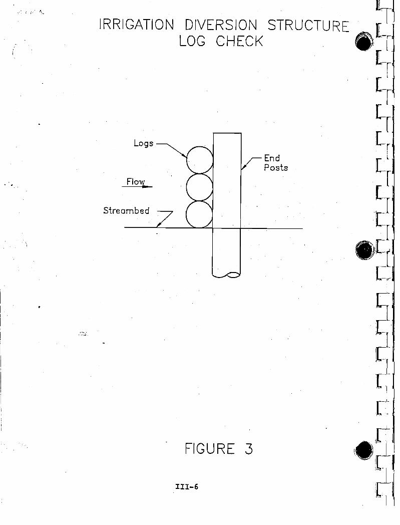
EndPosts .
FIGURE 3
111-6
Logs
Flow•
streambed
IRRIGATION DIVERSION STRUCTUREDESIGN CRITERIA AND SPECIFICATIONS
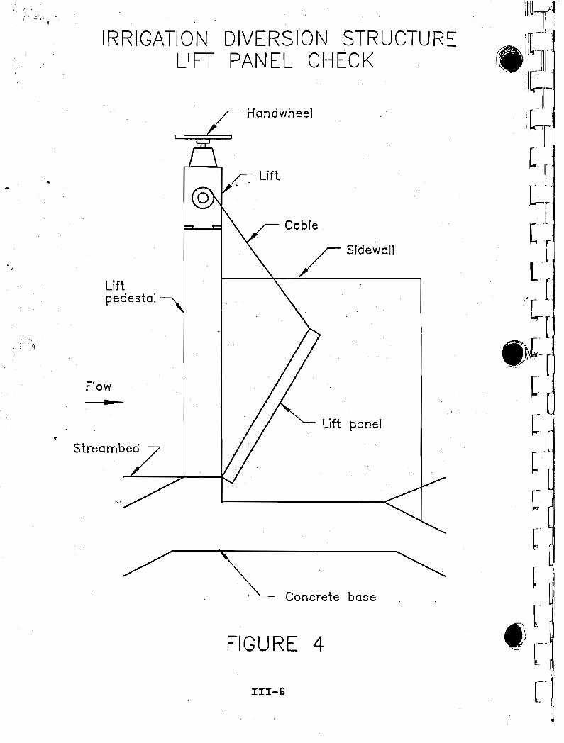
LIF~ PANEL CHECK
Description:
The lift panel check, also called overshot gate, consists of agate leaf, hinge, and hoist mechanism. See figure 4. In· afully opened position the gate leaf is horizontal and permits.full flow through the channel. The flow is reduced as thecable hoist raises the downstream edge of the gate. Themaximum position of the gate is 60 degrees. The gate can beset at any position between 0 and 60 degrees to set the headfor the diversion flow.
References:
1. Soil Conservation Service, National Engineering HandbookSection 5 Hydraulics, Soil Conservation Service,Washington D.C.
2. Soil Conservation Service, National Engineering Handbooksection 6 Structural Design, Soil Conservation Service,Washington D.C.
3. Ar.mtec Water Control Products, 2023 North Gateway Ave,Fresno California, 93727, 1-800-955-9587
Costs:
The approximate cost for a 10 foot wide gate with a 3 foothead is $3000 to $4000.
Installation Considerations:
1. Gates are available with fabricated side plates or forinstallation in a rectangular concrete section.
111-7
111-8
FIGURE 4
Sidewall
lift panel
Cable
Lift
Handwheel
'C Concrete base ~
~'i'l '
Liftpedestal
IRRIGATION DIVERSION STRUCTURELIFT PANEL CHECK
Flow
Streambed
:<\
I"~ "c:'.Il"t,~
I, I '
IRRIGATION DIVERSION STRUC~URE
DESIGN CRI~ERIA AND SPECIFIC~IONS
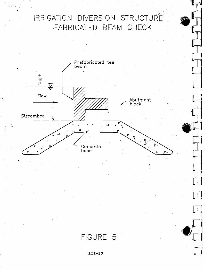
PREFABRICATED BEAM CHECK
Description:
The prefabricated beam check is constructed of a single or aseries of beams of the height required to divert theirrigation flow. See figure 5. This beam may be wood,reinforced concrete, or steel. For a relatively long span areinforced concrete T beam would probably be the mosteconomical. Prestressed beams may be used for extremely longspans
References:
1. Soil Conservation Service, National Engineering HandbookSection 5 Hydraulics, Soil Conservation Service,Washington D.C.
2. Soil Conservation Service, National Engineering HandbookSection 6 Structural Design, Soil Conservation Service,Washington D.C.
3. Soil Conservation Service, Engineering Design StandardsFar West States, West National Technical Center,Portland, Oregon, 1970.
Costs:
The approximate cost for a 20 foot wide check with a 3 foothead is $500 to $1000.
Installation Considerations:
1. A backhoe or small crane will probably be required toinstall the check.
2. Abutment blocks will be required to receive the ends ofthe beam and supply support.
I1I-9
Prefabricated teebeam
.~'~'; .
~~r~l}
;\:i~::'
Abutmentblock
.;.
III-10
Concretebase
FIGURE 5
..Flow
,.... !,~ ".'\~""
IRRIGATION DIVERSION STRUCTUR;E':,,FABRICATED BEAM CHECK
, ,
IRRIGATIO~ DIVERS%ON STRUCTUREDESIGN CRITERIA AND SPECIFICATIONS
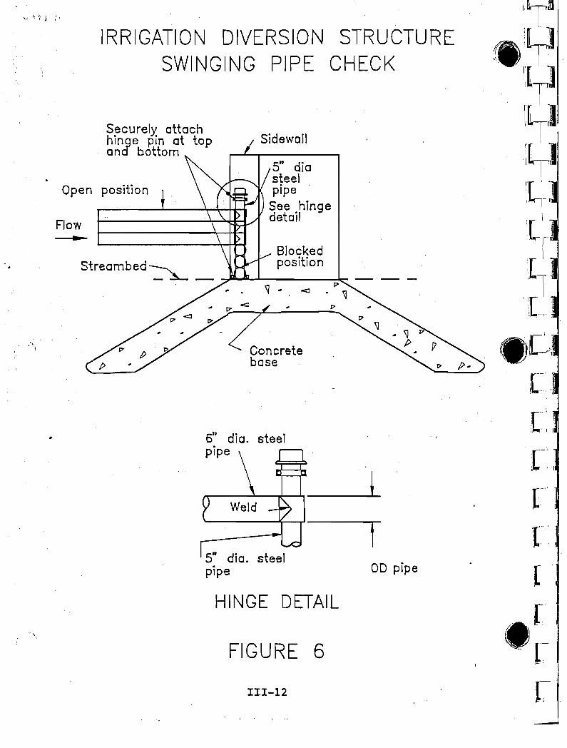
SWINGING PIPE CHECK
Description:
A swinging pipe check is constructed using 6 inch diametersteel pipe stacked horizontally across the watercourse. Seefigure 6. Each pipe is individually hinged on one side toprovide for checking the water in increments and to reduce theforce needed to remove a pipe under pressure. Channels withwidths up to 25 feet may be checked without interferingsupports. This clear opening eliminates problems with trashand the need to construct walkways over the channel. Cablesare required to be attached to the individual pipes when thereis a need to regulate the head while water is flowing over thecheck.
References:
III-II
Costs:
Installation Considerations:
. ,Soil Conservation Service, National Engineering Handbooksection 6 Structural Design, Soil conservation Service,Washington D.C.
1. Soil Conservation Service, National Engineering HandbookSection 5 Hydraulics, Soil Conservation Service,Washington D.C.
2.
The approximate unit cost for swinging pipe check is $70 to$150 per foot.
1. A simple foundation (usually concrete) is required.
',[,_l ,i
il • I 1
[-:1
[
', -,' II '
1- .
['
.~;~'~:.; ,
OD pipe
5" diosteelpipe
See hingedetail
Sidewall
Concretebase
FIGURE 6
111-12
HINGE DETAIL
5" dia. steelpipe
6»1 dia. steelpipe
Securely' attachhinge pin at topand bottom
IRRIGATION DIVERSION STRUCTURESWINGING PIPE CHECK
BlockedStreambed~ _ -7-"-L--_po_s_it_io_n~
Open position
Flow
~ .~ ".
IRRIGATION DIVERSION STRUCTUREDESIGN CRITERIA AND SPECIFICATIONS
WIRE FENCING AND GEOSYNTHETIC CHECK
Description:
A wire fencing and geosynthetic check consists of fence posts,fencing, and geosynthetic fabric to construct the requiredheadwall cutoff, and apron for an irrigation diversion dam.Figure 7 is a typical cross section for a fence structure witha height of 18 inches 'or less. Figure 8 is a typical crosssection for a fence structure with a height of'IS to 30inches. Standard "T" steel and/or.wood .. posts. may be used.The posts should be cut off a few inches.abovethe plannedfence height to minimize debris snags. .Numerous erosioncontrol netting, fabric, and silt fence products arecommercially available that may be 'used in conjunction withthe wire mesh fencing along' the headwall and apron of thestructure.
References:
1. Soil Conservation Service, National Engineering Handbooksection 5 Hydraulics, Soil Conservation Service,Washington D.C.
2. Soil Conservation Service, National Engineering HandbookSection 6 Structural Design, Soil Conservation Service,Washington D.C.
3. Designing with Geosynthetics, Robert M. Koerner, Ph.D.,P.E., Prentice Hall, Englewood Cliffs, New Jersey 07632
4. Industrial Fabrics Association International,Geotechnical Fabrics Report, Industrial FabricsAssociation International, 345 Cedar st., St. Paul,Minnesota 55101 .
5. American Society of Agricultural Engineers, EngineeringPractice: EP250.2, Specifications for Farm FenceConstruction, American Society of Agricultural Engineers,2950 Niles Road, St. Joseph, Michigan.
Costs:
The approximate unit cost for wire fencing and geosyntheticcheck is $10 to $25 per foot.
Installation Considerations:
1. .Minor shaping of the channel bottom or bank, bothupstream and downstream of the headwall, may be required
I.'
\ .~ "
'/!
to ensure that netting and fencing maintain contact withthe surface of the' ground.
, '.
, ~.
'.
III-14
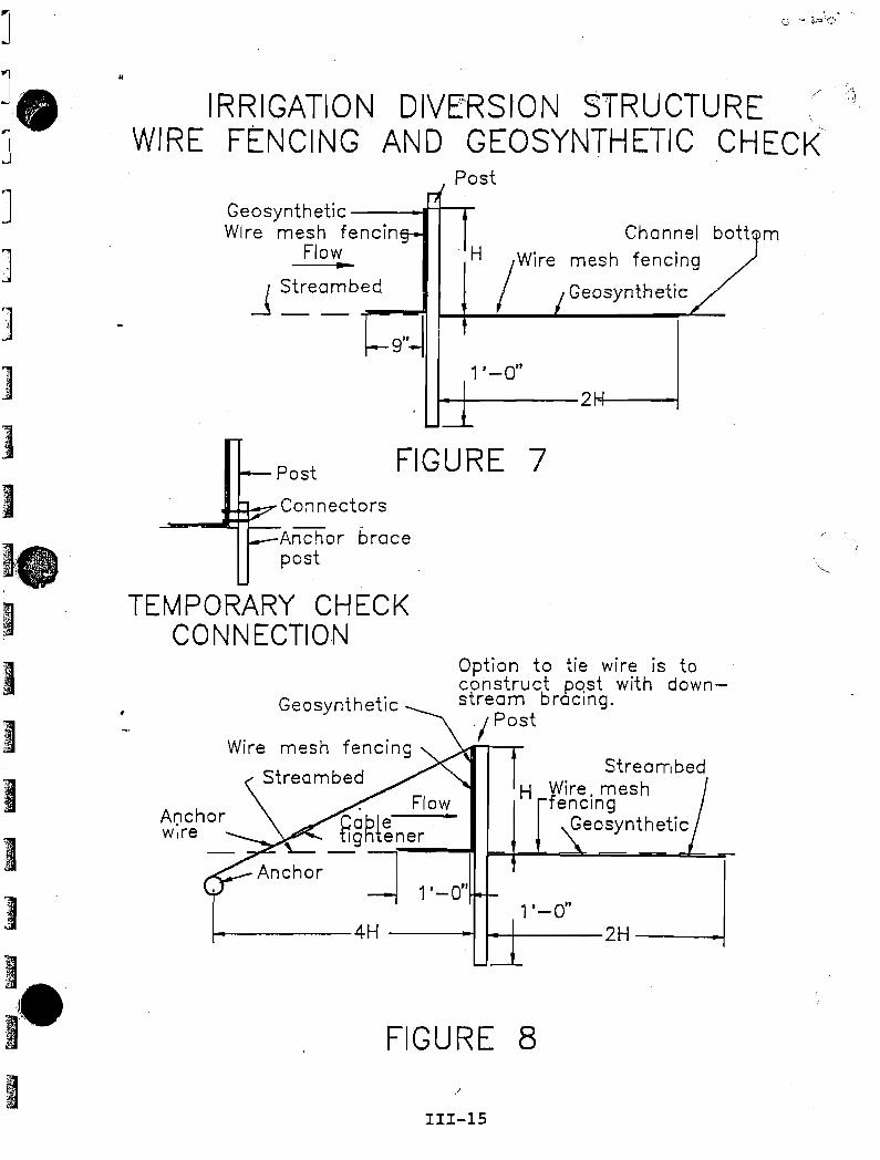
1'-0"
StreambedH W
fire. mesh
encmgGeosynthetic
H
Option to tie wire is toconstruct p.ost with downstream bracing.
/Post
Post
FIGURE 7
Geosynthetic
Channel bottJmmesh fencing /
J Streambe..:-d_-!I J--+-......._-'-G_e_o_sY_n_th_e_t'~lc"--
9"~ 1'-0" I.....-.+---2~
Wire mesh fencing
Streambed. Flow
tgRl~ner •
Anchor-'-I 1'-0"
FIGURE 8
111-15
.~ .. -.Q. ':It. ~""Z!~()
Geosynthetic ---t-t---rWire mesh fencin
Flow~
l-------4H ---I t--l---
~~Connectors~-ICI:
Anchor bracepost
IRRIGATION DIVE'RSIONSTRUCTUREWIRE F~NCING AND GEOSYNTHETIC CHECK~
TEMPORARY CHECKCONNECTION
"
]
J.]
J]
]
]1.~
)
I~····"
.~
IIIIII
I]
I,.",.),
I'~
I