Embed Size (px)
DESCRIPTION
rail
Citation preview
Proceedings2009 – 2010
We encapsulate rail know-how into software, technology and services to deliver value for
our customers. Our innovative, cost effective solutions answer the challenge of maximising
availability, reliability and capacity on operations, on track and on train.
On Operations, On Track, On Train
For further information E: [email protected] T: +44 (0)870 190 1000 W: deltarail.com
ON OPERATIONSSignalling Control Systems
Operational Planning & Management
ON TRACKInfrastructure Support
ON TRAINRolling Stock Maintenance
Rolling Stock Design
IECC image courtesy of Network Rail
The Institution of Railway Signal Engineers
INCORPORATED 1912
FOR THE
Advancement of the Science ofRailway Signalling
Proceedings 2009/2010
(Copyright Reserved)
PRICE TO NON-MEMBERS £50.00
Printed by Fericon Press Ltd (Tel: 0118 945 6100)
Cover Photo: Segovia High Speed Line, Spain taken on 26 May 2009 during the convention. Photo: Frans Heijnen
www.theclimateisrightfortrains.comwww.bombardier.com
We are proud of our history in manufacturing leading-edge signalling technology in the UK for over half a century. As a global leader in sustainable rail technology, we have installed signalling systems in over 50 countries, and some of the world’s busiest metros rely on our mass transit solutions.
From Madrid to Manilla, from Chile to China, millions of
passengers rely on our signalling systems every day
50 years ‘made in UK’ Bombardier Rail Control Solutions
3
ContentsPage
Contents ……………………………………………………………………………………………………………………………………………………………………………………3Portrait of Frans Heijnen …………………………………………………………………………………………………………………………………………………………4History of President …………………………………………………………………………………………………………………………………………………………………4The Council of the Institution 2009/2010 ……………………………………………………………………………………………………………………………6Addresses of Officers ………………………………………………………………………………………………………………………………………………………………8Institution Announcements ……………………………………………………………………………………………………………………………………………………9Institution Sales ………………………………………………………………………………………………………………………………………………………………………11Institution Awards …………………………………………………………………………………………………………………………………………………………………15Obituaries ………………………………………………………………………………………………………………………………………………………………………………17Eleventh Members’ Luncheon ……………………………………………………………………………………………………………………………………………19Presidential Address………………………………………………………………………………………………………………………………………………………………20Technical Meeting of the Institution, Wednesday 14th October 2009 “Maintenance: An Update on the …………24
Network Rail Approach ” by Steve Featherstone with a summary of the Discussion ………………………………………36Technical Meeting of the Institution, Wednesday 11th November 2009 “Signalling: Have We Lost the ……………38
Plot?” by Eddie Goddard with a summary of the Discussion ………………………………………………………………………………45Technical Meeting of the Institution, Wednesday 9th December 2009 “The Sustainable Railway ………………………47
Use of Advisory Systems for Energy Savings” by Ian Mitchell with a summary of the Discussion …………………56Technical Meeting of the Institution, Wednesday 13th January 2010 “Level Crossings in the Netherlands” ……58
by Jeroen Nedreiot with a summary of the Discussion …………………………………………………………………………………………62Technical Meeting of the Institution, Wednesday 10th February 2010 “Control Systems: Are Rail and ………………64
Air So Different?” by Gottfried Allmer with a summary of the Discussion …………………………………………………………71Technical Meeting of the Institution, Wednesday 10th March 2010 “Journey for Safe and Reliable Train …………72
Control Systems: Railway Signalling and Telecomms systems on Indian Railways” by Anshul Guptawith a summary of the Discussion………………………………………………………………………………………………………………………………81
Technical Meeting of the Australasian Section, Thursday 13th November 2009 “How Many Interlockings ………82Does It Take to Signal a Freight Train?” by Noel Burton BSc MIRSE
Technical Meeting of the Australasian Section, Friday 26th March 2010 “Moving Towards Goal-Based ……………90Safety Management” by Dr Holder M Becht Phd BInfTech(Hons)
Technical Meeting of the Australasian Section, Friday 26th March 2010 “Using Six Sigma to Improve Track ……98Circuit Reliability” by Peter McGregor BEng(Elect) Grad Dip (Systems) MIRSE
Technical Meeting of the South African Section, 24th August 2006 “CS90 VDU Based Train Control ………………108System with SPAD Detection” by Petrus J van den Bergh
Ninety-Seventh Annual Report …………………………………………………………………………………………………………………………………………113Ninety-Seventh Annual General Meeting ………………………………………………………………………………………………………………………13146th Annual Dinner ……………………………………………………………………………………………………………………………………………………………133IRSE International Convention 2009…………………………………………………………………………………………………………………………………1352009 Examination Results …………………………………………………………………………………………………………………………………………………143IRSE Strategy 2010-2014 ……………………………………………………………………………………………………………………………………………………144Axle Counter and Technology Siminar ……………………………………………………………………………………………………………………………146Younger Members’ 2009 Seminar and Technical Visit …………………………………………………………………………………………………149The Future Education and Training of Train Control Engineers and Technicians ……………………………………………………153Technical Visit to Aachen area of Germany ……………………………………………………………………………………………………………………156Australasian Section ……………………………………………………………………………………………………………………………………………………………160Dutch Section ………………………………………………………………………………………………………………………………………………………………………162Hong Kong Section ……………………………………………………………………………………………………………………………………………………………164Indian Section ………………………………………………………………………………………………………………………………………………………………………168Midland & North-Western Section……………………………………………………………………………………………………………………………………170Minor Railways Section ………………………………………………………………………………………………………………………………………………………171North American Section ……………………………………………………………………………………………………………………………………………………174Plymouth Section …………………………………………………………………………………………………………………………………………………………………178Scottish Section ……………………………………………………………………………………………………………………………………………………………………179Singaporean Section……………………………………………………………………………………………………………………………………………………………182Southern African Section ……………………………………………………………………………………………………………………………………………………182Western Section……………………………………………………………………………………………………………………………………………………………………188York Section …………………………………………………………………………………………………………………………………………………………………………194Younger Members’ Section ………………………………………………………………………………………………………………………………………………196Advertisers ……………………………………………………………………………………………………………………………………………………………………………198
4
It took the best part of 70 years for council tocome to the conclusion that the Institution'sPresident did not necessarily have to be Britishborn. We have not quite achieved internationalstatus in that respect but with the arrival of FransHeijnen, we can now boast of seven Presidentswhose origins are other than the UK.
Frans is our second Dutch President, coming onlytwo years after Wim Coenraad with theconsequence that The Netherlands is now only onepoint behind France in our European Champion'sLeague. Germany and Switzerland trail with equalpoints and goal difference.
He was born in Leiden on the day beforeChristmas in 1947. Birthday and Christmas comingso close can have its drawbacks as tight fistedrelations and friends will try to fob you off with onepresent to cover both events. However, the earlyarrival in his life of a clockwork driven train setprovided a partial solution to the dilemma — asection of straight track for his birthday leavingSanta to drop the curved section down the chimney.
Apart from the clockwork train, Frans' family hasbeen railway free. There is a tenuous link withtransport through a grandfather who was a seagoing chef. His mother's forebears were farmers.
Frans’ father was an accountant having his ownbusiness in Leiden. He thought that Frans and hisbrother Adriaan would eventually come into thebusiness enabling him to enjoy an early retirementbut father had to reluctantly accept that there is noaccounting for tastes. Both lads finished up in therailway signal engineering industry.
The two boys and their sister were brought up inLeiden going to primary and secondary schools inthe town.
Railways might not have been in the family but Franswas infected at an early age, as were so many
Presidents before him, with this incurable disease.At the age of ten he discovered that, for a triflingsum of money, he could buy a platform ticket andwander Leiden station for the rest of the daywatching the trains go by. Tram rides standing nextto the driver were a regular experience as Leidenhad a tram system into the early sixties.
Holland's railways had suffered dreadfully duringthe war but, by this time, restoration of the networkwas complete with modern electric and diesellocomotives hauling the trains. There would be theintensive suburban train services and the longdistance expresses heading for fascinating and, to ayoung boy, exotic destinations throughout Europe.
It was not all railways. Electronics proved irresistibleand he constructed a wide range of electronicdevices, many of which worked first time.
He joined the Scout movement as a Cub, maturingto be a Scout and finishing as a Rover; anappropriate line of progress considering hissubsequent career. His skills with electronics found aplace in Scouting when he built and operated a radiotransmitter for the 1966 Jamboree in theNetherlands.
Military service was still obligatory for men in thosedays and Frans was conscripted into the Dutch armyfor two years. Ask him for his memories of his timeserving Queen and Country and you will receive thevery brusque response of "waste of time"! Storesmanagement was neither interesting norchallenging apart from the brief period when a beertent came under his control. It did allow himhowever to study mathematics during workinghours.
Now came the time to consider a career. He hadcome right through school with two ideas, electricalengineering or accountancy, but indecision couldlast no longer. Technology prevailed and so he went
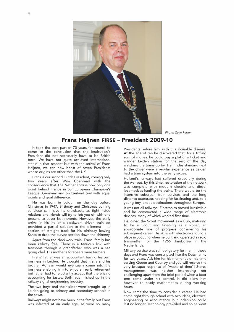
Frans Heijnen FIRSE – President 2009-10Photo: Colin Porter
FRANS HEIJNEN 5
to Delft University to study electrical and electronicengineering, graduating with a Masters inTransmission of Information. The first intents to getvideo from the platform into the cab for safe traindeparture were the subject of his degree work.
Whilst he was at Delft, he married a Spanish ladyand, immediately after graduation, the happycouple set off for Madrid where they set up home.
Spain was where Frans commenced his railwayindustry career, a career that was to have so manytwists and turns over the next forty years with 12employers and countless positions. Today's generationdoes not expect to work for just the one company andwill probably find nothing remarkable in his successionof employers but way back then, most people tendedto retire from the company where they first started. Hehas sat on each side of the table (customer, supplierand consultant) at least twice in his career.
Frans' first employer was Abengoa - a licensee of GRSfor signal engineering in Spain where he remained forten years, a remarkable period of stability consideringwhat was to follow. You would need to sit down withhim for an hour or so to hear the full story. Hissubsequent wanderings took him to Bosch, famousfor the manufacture of tooling and components forcars. Then it was signal research with NS in Utrecht fora short period before returning to Spain. Now it doesget confusing with spells working for a succession ofcompanies that included Amper, Transmitton (nowSiemens), ENA Telecommunications and TIFSA, whichis one of the engineering branches of RENFE (nowADIF). There he was involved with quality control,installation and safety cases for the AVE line betweenMadrid and Seville as Head of Quality for theElectrical Installations, including signalling, telecoms,passenger information systems, power distribution,catenaries and substations.
Suddenly, his personal high speed career journey hitthe buffers and he found himself jobless. Spanishpoliticians can be as devious as their compatriotselsewhere in the world and they did not like themessage that Frans was giving them about the needfor safety cases and safety certificates. Undamaged bythis collision, he took the opportunity to study for anExecutive MBA at the Instituto de Empresa in Madrid.That under his belt, he once again returned to theNetherlands, this time to the NS engineering officewhich later morphed into Holland Railconsult and thenbecame Movares which it still is. It was a busy timecovering project management, technical direction andthe formative years of ERTMS, partly spend in Brusselsat the ERTMS Users Group as Systems Director.
Nevertheless, eight years in the same country wasbeginning to take its toll on him and when InvensysRail suggested he might like to be their Director,Technology, (later renamed to Vice PresidentTechnology – a nice American touch –) atChippenham, he was off like a shot. Another countryand another language to master. He was already asfluent in Spanish as in his native Dutch and nowcame an opportunity to fine tune his English.
Frans has always been interested in the personnelside of management and close to retirement optedto leave the technical side of Invensys to be VicePresident Industrial Relations for the company. Moreacronyms came into his life as the post hadinternational dimensions with considerableinvolvement in UNISIG and ERA.
Finally retirement came at the end of 2007 though ithas been retirement in name only. You will not besurprised to hear that he took the opportunity onretiring to try another country and another language.Home is now near Aachen and his German isprogressing very satisfactorily indeed. Actually, it isrumoured that he has retired underground. He is"green" with a determination to have a carbonfootprint of small dimensions. There's a turf roof, aheat pump for heating and hot water but,surprisingly considering his Dutch origins, nowindmill. The front door and the sails require to beinterlocked to operate a signal indicating when it issafe to enter or leave the house. It should be thenext project.
Consultancy and charitable work has filled or rather,overfilled his life ever since. Accountancy, whichclearly has lain dormant within him for forty or moreyears, has emerged with retirement. He was involvedin the management of a charity in Leiden thatprovides a residence for the elderly. Railways havenot been rejected as Frans is the treasurer of theFriends of the National Railway Museum in Utrecht.With Aachen being so near to Brussels, he has beenable to continue with his professional involvement inthe industry. Being over 60 means that his travelcosts are negligible, a feature not normallyassociated with those employed in Brussels.
Electronics continue to be a fascination. Hepossesses a remarkable collection of computersgoing right back to pre-historic times – pre-historicin the micro processor terms. And they all work!
In retirement, he's hoping to find the time to explorethe world of Buddhism. He's been to Tibet twiceand, perhaps could be in a position to advise a futurePresident of somewhere novel for a Convention.
His second wife, Alphonsine who is from theNetherlands, has a strong background and interestin education and they have together been sponsorsfor the creation of a special school.
There are grandchildren to consider but,unfortunately, they do not live near. Both his son anddaughter are married and live in Madrid and that iswhere he has to go to see his grandchildren.Alphonsine's grandchildren live in Bognor Regiswhich is probably more difficult to reach than Madrid.
Every President has his own unique features but it isstrange how often there is commonality. Our longserving unofficial recruitment manager, Jim Waller,was responsible for persuading Frans to join theInstitution way back in his Abengoa days. He joinedas a Fellow coincidentally with attendance at thesecond Spanish Convention in 1984, followed in thesame year with our first “Aspect" conference. Afterthat he progressed through the ranks serving on theusual range of committees.
He accepts the fact that railway professionalinvolvement will inevitably diminish with time but hehas already started his alternative life of doingsomething for society. This will become obvious in hisprogramme of not so technical papers. It's time themembers have the human side of the industry broughtto their attention. There's as much scope for discussionthere as in matters of an engineering nature.
So will there be third Dutch president in the nearfuture? No reason why not, as the Dutch section ofthe IRSE has over 120 members. There has to bepotential within that number.
The Institution of Railway Signal EngineersINCORPORATED 1912
SESSION 2009/2010
OFFICERS AND COUNCIL
PRESIDENT
F HEIJNEN ……………………………………………………………………………………………………………………………………………………………………Aachen
VICE-PRESIDENTS
P JENKINS………………………………………………………………………………………………………………………………………………………………………London
Mrs C PORTER ………………………………………………………………………………………………………………………………………………………………London
COUNCIL
CO-OPTED PAST PRESIDENTS
W J COENRAAD……………………………………………………………………………………………………………………………………………………………Utrecht
J D FRANCIS ………………………………………………………………………………………………………………………………………………………Chippenham
J PORÉ …………………………………………………………………………………………………………………………………………………………………………………Paris
FELLOWS
F HOW ……………………………………………………………………………………………………………………………………………………………………………London
J IRWIN……………………………………………………………………………………………………………………………………………………………………………London
I MITCHELL ………………………………………………………………………………………………………………………………………………………………………Derby
C R PAGE …………………………………………………………………………………………………………………………………………………………………Singapore
A PARKER ………………………………………………………………………………………………………………………………………………………………………London
DR A F RUMSEY ……………………………………………………………………………………………………………………………………………………………Canada
C SEVESTRE ………………………………………………………………………………………………………………………………………………………………………Paris
A SIMMONS …………………………………………………………………………………………………………………………………………………………………London
G J SIMPSON ………………………………………………………………………………………………………………………………………………………………London
D N WEEDON ………………………………………………………………………………………………………………………………………………………………London
MEMBERS
J J AITKEN………………………………………………………………………………………………………………………………………………………………………Sydney
I ALLISON …………………………………………………………………………………………………………………………………………………………Loughborough
P J GRANT………………………………………………………………………………………………………………………………………………………………Wimbledon
A S KORNAS ………………………………………………………………………………………………………………………………………………………………………York
D WOODLAND ……………………………………………………………………………………………………………………………………………………………London
N WRIGHT ……………………………………………………………………………………………………………………………………………………………………Swindon
ASSOCIATE MEMBERS
Miss L C SIMÓN VENA…………………………………………………………………………………………………………………………………………………MadridD YOUNG ………………………………………………………………………………………………………………………………………………………………………London
6
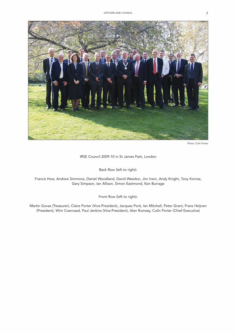
IRSE Council 2009-10 in St James Park, London
Back Row (left to right):
Francis How, Andrew Simmons, Daniel Woodland, David Weedon, Jim Irwin, Andy Knight, Tony Kornas, Gary Simpson, Ian Allison, Simon Eastmond, Ken Burrage
Front Row (left to right):
Martin Govas (Treasurer), Claire Porter (Vice-President), Jacques Poré, Ian Mitchell, Peter Grant, Frans Heijnen(President), Wim Coenraad, Paul Jenkins (Vice-President), Alan Rumsey, Colin Porter (Chief Executive)
OFFICERS AND COUNCIL 7
Photo: Colin Porter

8
Addresses of Officers
Chief ExecutiveC H PORTER
4th Floor, 1 Birdcage Walk, Westminster, London SW1H 9JJTelephone: +44 (0)20 7808 1180 Facsimile: +44 (0)20 7808 1196 Email: [email protected]
TreasurerM GOVAS
2 The Droveway, Haywards Heath, West Sussex RH16 1LL
Proceedings EditorA PARKER
Network Rail, Floor 9, 40 Melton Street, London NW1 2EETelephone: 020 7557 9385 Email: [email protected]
Australasian SectionChairman: J AITKEN Vice-Chairman: S BOSHIERSecretary: G WILLMOTT Treasurer: G WILLMOTT
Dutch SectionChairman: J OONINCX Vice-Chairman: P MUSTERS
Secretary: A FÖRRER Treasurer: P OTTEN
Hong Kong SectionChairman: L Y LAM Vice-Chairman: C P LUNG
Secretary: Y F SUNG Treasurer: T Y NG
Indian SectionChairman: Sh. K K BAJPEYEE Vice-Chairman: Sh. S LAHIRI
Secretary: Sh. A GUPTA Treasurer: Sh. A GUPTA
Midland & North Western SectionChairman: G HILL Vice-Chairman: P DUGUAYSecretary: B REDFERN Treasurer: C WILLIAMS
Minor Railways SectionChairman: I ALLISON Vice-Chairman: D HELLIWELL
Secretary: M HUIBERS Treasurer: T HODGSON
North American SectionChairman: D THURSTON Vice-Chairman: K BISSET
Secretary: G YOUNG Treasurer: G YOUNG
Plymouth SectionChairman: A LOVETT Vice-Chairman: R NETTLETON
Secretary: D CAME Treasurer: D CAME
Scottish SectionChairman: Mrs L HUNTER Vice-Chairman: C HOURSTON
Secretary: S WRIGHT Treasurer: B McKENDRICK
Singaporean SectionChairman: M APPLEYARD Vice-Chairman: R SHIELD
Secretary: I TOMLINS Treasurer: I TOMLINS
Southern African SectionChairman: B VAN DER MERWE Vice-Chairman: B OSTENDORF
Hon Secretary: P MEYER Treasurer: J C VAN DE POL
Western SectionChairman: P DUGGAN Vice-Chairman: M PETERS
Secretary: M PETERS Treasurer: A SCARISBRICK
York SectionChairman: J MAW Vice-Chairman: D GILLANDERS
Secretary: J MAW Treasurer: A P SMITH
Younger Members’ SectionChairman: L HUNTER
Secretary: M FENNER Treasurer: A WHITTON
9
Institution Announcements
(The price and subscription rates and other information given in these announcements are current at the date of publication – August 2010)
INSTITUTION WEB-SITEThe website www.irse.org contains up to date
information about the Institution. There is amembers’ area for updating personal contact details,access to some publications and for payment ofsubscriptions. In the general area, it is possible tobook events and order publications and goods. Thefeatures provided by the website are continuallybeing expanded and information about changes isgiven both on the site itself and in IRSE NEWS.
CHANGE OF ADDRESSConsiderable inconvenience is created when
members fail to notify changes of postal or e-mailaddresses. Will members please inform the Institutionoffice immediately of any such alteration, or completethe notification page on the website to ensure promptdelivery of IRSE NEWS and other notices.
TRANSFER TO HIGHER GRADE OFMEMBERSHIP
Members sometimes remain in one grade ofmembership when their experience andprofessional standing has become such as to entitlethem to transfer to a higher one. The Council invitesany such person to apply for a transfer using anapplication form available from the website or theInstitution office.
TECHNICAL PAPERSThe Council invites members of all grades to
submit papers for presentation at technical meetingsin London or at local meetings in the Sections.
Papers should consist of between four thousandand six thousand words and while no limit is placedon the number of illustrations an author uses duringhis reading of the paper, the number printed in IRSENEWS and published in the Journal of Proceedingsmust not exceed twelve.
Guidelines for the presentation of papers areincluded on the website.
COPIES OF LONDON TECHNICAL PAPERS
Copies of the technical papers read in London willbe published in IRSE NEWS and circulated to allmembers.
SUBSCRIPTIONS AND REMITTANCESMembers are reminded that in accordance with
the Articles of Association subscriptions are payableon election or by the 1st July each year. Thesubscription rates are shown on the websitewww.irse.org.
Members are reminded that prompt payment ofsubscriptions is required. The Institution is gratefulto the vast majority of members who keepadministration costs down by paying at the timerequested. The Treasurer is obliged to send outnotices of arrears to members who have not paid bythe due date.
Subscriptions can be paid via IRSE Online atwww.irse.org or they should be sent to theInstitution office in London, unless you belong toeither the Indian or Southern African Sections. Localarrangements apply to members of these Sections.All cheques and money orders, especially thosefrom overseas, should be crossed. Facilities to payby Direct Debit from UK banks are available onrequest.
The attention of members is directed to theclauses in the Articles of Association under whichneither notices nor copies of Proceedings may besent to those who are in arrears with theirsubscriptions beyond a certain time.
UK Income Tax – the annual subscription to theInstitution of Railway Signal Engineers is treated as anallowance expense under Section 16 of the FinanceAct 1958 and should be included in your Tax Returnin the section headed “Expenses in Employment –Fees or subscriptions to professional bodies”.
Members of the Institution who have retired andhave paid full subscriptions for at least ten years areentitled to continue membership of the Institution athalf the full rate applicable to their class ofmembership. Similar arrangements are available toothers in special need on application to theTreasurer. Members of 50 years standing are notrequired to pay subscriptions.
LIBRARYThe Institution Library is incorporated with the
Library of the Institution of Engineering &Technology. It is situated at the Institution ofEngineering & Technology’s building at Savoy Place,Victoria Embankment, London WC2R 0BL, UK.Members of the Institution of Railway SignalEngineers have been granted the same privilegeswith respect to it as those enjoyed by members ofthe Institution of Engineering & Technology, and theentire collection is open to them on equal terms.
The Reference Library, which contains a ReadingRoom in which a great number of technicalperiodicals are always available, as well as a largegeneral collection, is open from 09.00 to 17.00Monday-Friday.
Any member of the IRSE entering the Libraryshould sign their name in the book provided for thatpurpose.
The use of the Lending Library, which is openduring the same hours as the Reference Library andwhich contains the principal works relating toelectrical engineering, its applications and alliedsubjects including, of course, railway signalling, isgoverned by the following rules, which must bestrictly adhered to:
When applying for a book by post a member ofthe IRSE must state their grade of membership. Allcommunications should be addressed to theLibrarian, Institution of Engineering & Technology,at the address already given.
Anyone wishing to donate any books to thecollection should contact the Honorary Librarianthrough the London office.
SIGNAL AND TELEGRAPH TECHNICALSOCIETIES
The following S&T Technical Society is affiliated tothe Institution:
The London Underground Signal & ElectricalEngineers’ Society –
General Secretary: M.B. SimmondsThales RSS Ltd, 2nd Flr, 4 Quadrant House,Thomas More Square, Thomas More Street,London, E1W 1YW, UK. Email:[email protected]: 020 3300 6192
IRSE PROFESSIONAL EXAMINATION The aim of the examination is to establish the
professional competence in signal and/or railwaytelecommunications engineering of educationallyqualified electrical, electronic and communicationsengineers.
It is intended to test the main concepts of thesubject material without bias to any one railwaypractice and is designed to demonstrate that astudent has reached the necessary professionaleducational standard required of a signalling ortelecommunications engineer for CorporateMembership of the Institution.
This standard is typified by the exercising ofjudgement in the preparation, assessment,amendment or application of specifications andprocedures, and is applicable to personnel engagedin the following activities:
• Signalling / telecommunications principles,practices, rules and regulations for the safeoperation of railway traffic.
• Design and development of signalling/telecommunications equipment and systems.
• Preparation and understanding of equipmentdrawings and specifications and/or design.
• Planning, site installation and testing ofsignalling/telecommunications equipment andsystems.
• Practices related to assembly, wiring and testingof signalling/telecommunications equipmentand systems.
• Maintenance and servicing of signalling/
telecommunications equipment and systems.
In order to meet the examination requirements forcorporate membership, candidates must, within aperiod of five years, obtain a pass in Module 1, plusthree of the remaining six optional modules.
It is possible to obtain exemptions from individualmodules where you can demonstrate that you havepassed an examination by a recognised body whichhas substantially covered the syllabus of a particularIRSE examination module. Due to the specialisednature of the IRSE Examination. The scope forexemption is fairly limited.
Claims for exemption must be made within fiveyears of obtaining the particular qualification forwhich recognition is being claimed. The reason forthis condition is that the exemption is based oninformation that may not be available where aqualification has been discontinued or changed.
MODULE 1
Safety of Railway Signalling and Communications– No exemptions will be given.
MODULE 2
Signalling the Layout – Please apply, noexemptions currently agreed.
MODULE 3
Signalling Principles – Please apply, noexemptions currently agreed.
MODULE 4
Communications Principles – This is the mostcommonly sought after exemption. Many of theapplicants for exemption claim thattelecommunications has been part of their Degreecourse and that, on this basis, exemption should begranted. Unfortunately it has been clear that thecontent of the telecommunications element within atypical university Engineering Degree is, at best, abasic overview. Occasionally, students study atelecommunications topic for their final year project,but these tend to be about a research topic narrowlyspecialising in a particular field and the Council isnot convinced that such study justifies moduleexemption. As a basic guideline, therefore, pleasedo not ask for exemption to this module unless:your university study has predominantly been intelecommunications; or your university study hasincluded telecommunications and your presentcareer is railway telecommunications engineering.
MODULE 5
Signalling & Control Equipment, ApplicationsEngineering – Please apply, no exemptions currentlyagreed.
MODULE 6
Communications Equipment, ApplicationsEngineering – Please apply, no exemptions currentlyagreed.
MODULE 7
Systems, Management & Engineering – Pleaseapply, no exemptions currently agreed.
The examination is generally held in October ofeach year and the regulations are available from theHead Office or on the website. The followingsupport materials are also available to students:
INSTITUTION ANNOUNCEMENTS10
• Information for Students
• Examination Syllabus
• Reading List
• Past Papers
• Model Answers
• Examiners Reports
• Updates of Examination Material
THE THORROWGOOD SCHOLARSHIP AWARD
The Thorrowgood Scholarship is awardedannually to a student member excelling in theInstitution’s Professional Examination. The awardconsists of the Institution’s ThorrowgoodScholarship Medallion, and a cheque in the region
of £1,500, that is presented at the Annual GeneralMeeting of the Institution in the April following theexamination.
The terms of the Thorrowgood bequest requirethat it should be utilised to assist the developmentof young engineers employed in the railwaysignalling and telecommunications field. Arequirement of the award is that it is used to financea study tour of railway and/or signalling installationsor manufacturing facilities, usually in a foreignadministration, and that the award holder presents areport about the study tour to the YoungerMembers’ Section.
To be eligible for the award students are usuallyexpected to have sat the required four modules inthe same year, and achieved outstanding results.
INSTITUTION ANNOUNCEMENTS 11
Institution SalesAll items are available from the Institution office. A priced list of publications and other items such as anInstitution tie, with preferential rates for members is available on the website.
For all your engineering and signalling needs contactHenry Williams on Tel. +44 (0) 1325 462722
Email. [email protected] Web. www.hwilliams.co.uk
Giving off all the right Signals
• Mimic Panels
• Control Panels
• Fully Wired Location Cases
• FSPs (Functional Supply Points)
• DNO & Points Heating
• Fishplates
• Treadles
12
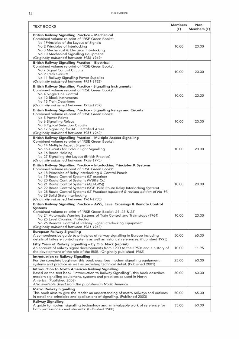
TEXT BOOKS Members Non-(£) Members (£)
British Railway Signalling Practice – MechanicalCombined volume re-print of ‘IRSE Green Books’:
No 1Principles of the Layout of SignalsNo 2 Principles of Interlocking 10.00 20.00No 3 Mechanical & Electrical InterlockingNo 10 Mechanical Signalling Equipment
(Originally published between 1956-1969)
British Railway Signalling Practice – ElectricalCombined volume re-print of ‘IRSE Green Books’:
No 7 Signal Control Circuits 10.00 20.00No 9 Track CircuitsNo 11 Railway Signalling Power Supplies
(Originally published between 1951-1952)
British Railway Signalling Practice - Signalling InstrumentsCombined volume re-print of ‘IRSE Green Books’:
No 4 Single Line Control 10.00 20.00No 12 Block InstrumentsNo 13 Train Describers
(Originally published between 1952-1957)
British Railway Signalling Practice - Signalling Relays and CircuitsCombined volume re-print of ‘IRSE Green Books:
No 5 Power PointsNo 6 Signalling Relays 10.00 20.00No 8 Typical Selection CircuitsNo 17 Signalling for AC Electrified Areas
(Originally published between 1951-1962)
British Railway Signalling Practice – Multiple Aspect SignallingCombined volume re-print of ‘IRSE Green Books’:
No 14 Multiple Aspect Signalling No 15 Circuits for Colour Light Signalling 10.00 20.00No 16 Route HoldingNo 27 Signalling the Layout (British Practice)
(Originally published between 1958-1975)
British Railway Signalling Practice – Interlocking Principles & SystemsCombined volume re-print of ‘IRSE Green Books’:
No 18 Principles of Relay Interlocking & Control PanelsNo 19 Route Control Systems (LT practice)No 20 Route Control Systems (WB&S Co)No 21 Route Control Systems (AEI-GRS)) 10.00 20.00No 22 Route Control Systems (SGE 1958 Route Relay Interlocking System)No 28 Route Control Systems (LT Practice) (updated & revised edition of No 19)No 29 Solid State Interlocking
(Originally published between 1961-1988)
British Railway Signalling Practice – AWS, Level Crossings & Remote Control SystemsCombined volume re-print of ‘IRSE Green Books’: 24, 25 & 26)
No 24 Automatic Warning Systems of Train Control and Train-stops (1964) 10.00 20.00No 25 Level Crossing ProtectionNo 26 Remote Control of Railway Signal Interlocking Equipment
(Originally published between 1961-1967)
European Railway SignallingA comprehensive guide to principles of railway signalling in Europe including 50.00 65.00details of fail-safe control systems as well as historical references. (Published 1995)
Fifty Years of Railway Signalling – by O.S. Nock (reprint)An account of railway signal developments from 1900 to the 1950s and a history of 10.00 11.95the development of the role of the IRSE. (Originally published 1962)
Introduction to Railway SignallingFor the complete beginner, this book describes modern signalling equipment, 25.00 60.00systems and practice as well as providing technical detail. (Published 2001)
Introduction to North American Railway SignallingBased on the text book “Introduction to Railway Signalling”, this book describes 30.00 60.00modern signalling equipment, systems and practices as used in NorthAmerica. (Published 2008)Also available direct from the publishers in North America.
Metro Railway Signalling This book aims to give the reader an understanding of metro railways and outlines 50.00 65.00in detail the principles and applications of signalling. (Published 2003)
Railway SignallingA guide to modern signalling technology and an invaluable work of reference for 35.00 60.00both professionals and students. (Published 1980)
PUBLICATIONS
13PUBLICATIONS
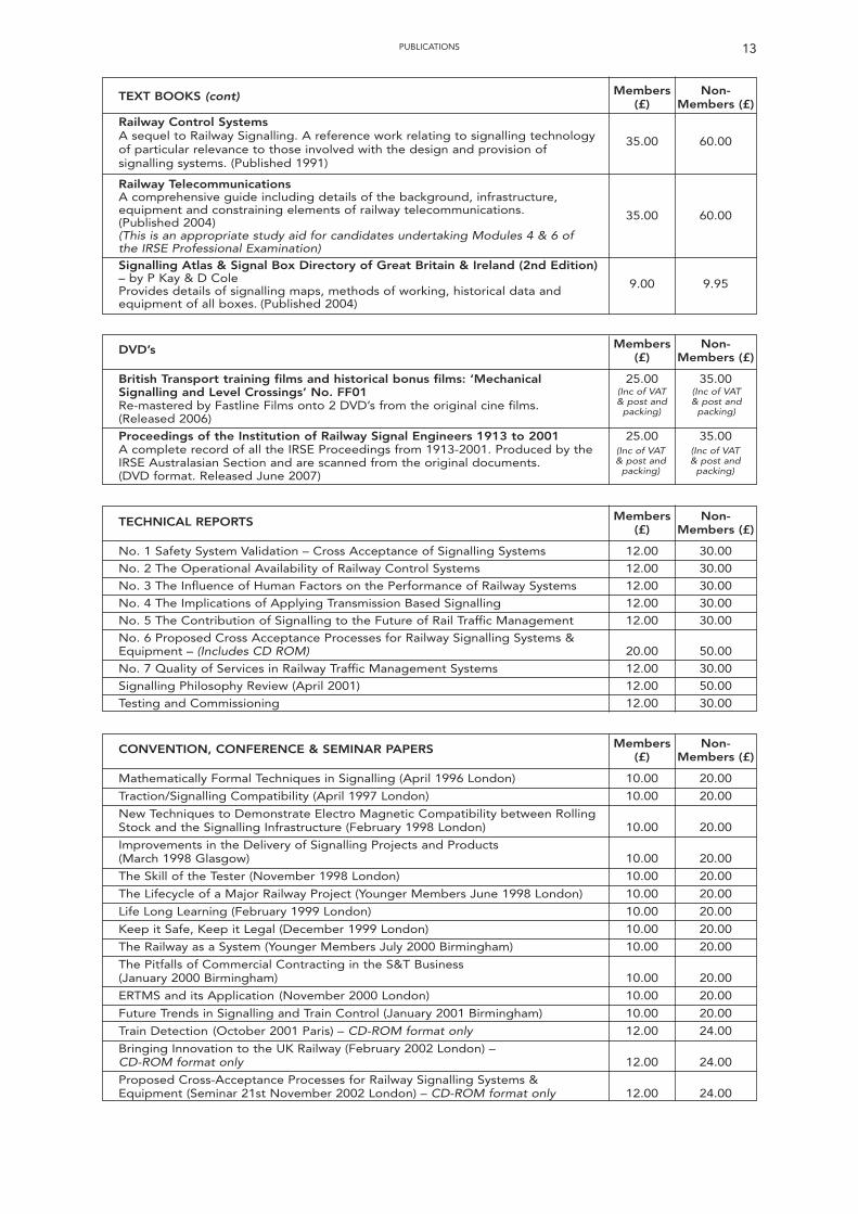
TEXT BOOKS (cont) Members Non-(£) Members (£)
Railway Control SystemsA sequel to Railway Signalling. A reference work relating to signalling technology 35.00 60.00of particular relevance to those involved with the design and provision of signalling systems. (Published 1991)
Railway TelecommunicationsA comprehensive guide including details of the background, infrastructure, equipment and constraining elements of railway telecommunications. 35.00 60.00(Published 2004)(This is an appropriate study aid for candidates undertaking Modules 4 & 6 of the IRSE Professional Examination)Signalling Atlas & Signal Box Directory of Great Britain & Ireland (2nd Edition) – by P Kay & D Cole 9.00 9.95Provides details of signalling maps, methods of working, historical data and equipment of all boxes. (Published 2004)
DVD’s Members Non-(£) Members (£)
British Transport training films and historical bonus films: ‘Mechanical 25.00 35.00Signalling and Level Crossings’ No. FF01Re-mastered by Fastline Films onto 2 DVD’s from the original cine films.(Released 2006)
Proceedings of the Institution of Railway Signal Engineers 1913 to 2001 25.00 35.00A complete record of all the IRSE Proceedings from 1913-2001. Produced by the IRSE Australasian Section and are scanned from the original documents.(DVD format. Released June 2007)
TECHNICAL REPORTS Members Non-(£) Members (£)
No. 1 Safety System Validation – Cross Acceptance of Signalling Systems 12.00 30.00
No. 2 The Operational Availability of Railway Control Systems 12.00 30.00
No. 3 The Influence of Human Factors on the Performance of Railway Systems 12.00 30.00
No. 4 The Implications of Applying Transmission Based Signalling 12.00 30.00
No. 5 The Contribution of Signalling to the Future of Rail Traffic Management 12.00 30.00
No. 6 Proposed Cross Acceptance Processes for Railway Signalling Systems & Equipment – (Includes CD ROM) 20.00 50.00
No. 7 Quality of Services in Railway Traffic Management Systems 12.00 30.00
Signalling Philosophy Review (April 2001) 12.00 50.00
Testing and Commissioning 12.00 30.00
CONVENTION, CONFERENCE & SEMINAR PAPERS Members Non-(£) Members (£)
Mathematically Formal Techniques in Signalling (April 1996 London) 10.00 20.00
Traction/Signalling Compatibility (April 1997 London) 10.00 20.00
New Techniques to Demonstrate Electro Magnetic Compatibility between Rolling Stock and the Signalling Infrastructure (February 1998 London) 10.00 20.00
Improvements in the Delivery of Signalling Projects and Products (March 1998 Glasgow) 10.00 20.00
The Skill of the Tester (November 1998 London) 10.00 20.00
The Lifecycle of a Major Railway Project (Younger Members June 1998 London) 10.00 20.00
Life Long Learning (February 1999 London) 10.00 20.00
Keep it Safe, Keep it Legal (December 1999 London) 10.00 20.00
The Railway as a System (Younger Members July 2000 Birmingham) 10.00 20.00
The Pitfalls of Commercial Contracting in the S&T Business (January 2000 Birmingham) 10.00 20.00
ERTMS and its Application (November 2000 London) 10.00 20.00
Future Trends in Signalling and Train Control (January 2001 Birmingham) 10.00 20.00
Train Detection (October 2001 Paris) – CD-ROM format only 12.00 24.00
Bringing Innovation to the UK Railway (February 2002 London) – CD-ROM format only 12.00 24.00
Proposed Cross-Acceptance Processes for Railway Signalling Systems & Equipment (Seminar 21st November 2002 London) – CD-ROM format only 12.00 24.00
(Inc of VAT& post and
packing)
(Inc of VAT& post and
packing)
(Inc of VAT& post and
packing)
(Inc of VAT& post and
packing)
14 PUBLICATIONS
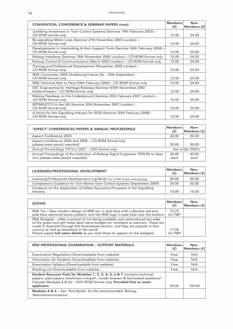
CONVENTION, CONFERENCE & SEMINAR PAPERS (cont) Members Non-(£) Members (£)
Justifying Investment in Train Control Systems (Seminar 19th February 2003) –CD ROM format only 12.00 24.00
Re-signalling Metro Lines (Seminar 27th November 2003 London) – CD-ROM format only 12.00 24.00
Developments in Interlocking & their Support Tools (Seminar 26th February 2004) –CD ROM format only 12.00 24.00
Railway Interfaces (Seminar 18th November 2004 London) – CD-ROM format only 12.00 24.00
Railway Control & Communications (March 2005 London) – CD ROM format only 12.00 24.00
Training and Professional Development (November 2005 London) - CD ROM format only 12.00 24.00
IRSE Convention 2005 Strasbourg France (26 – 30th September) - CD ROM format only 12.00 24.00
IRSE Technical Visit to Paris (24th February 2006) - CD ROM format only 12.00 24.00
S&T Engineering for Heritage Railways (Seminar 4/5th November 2006 Kidderminster) – CD ROM format only 12.00 24.00
Making Headway on the Underground (Seminar 20th February 2007 London) – CD ROM format only 12.00 24.00
ERTMS/ETCS in the UK (Seminar 20th November 2007 London) - CD ROM format only 12.00 24.00
A Vision for the Signalling Industry for 2030 (Seminar 20th February 2008) - CD ROM format only 12.00 24.00
‘ASPECT’ CONFERENCES PAPERS & ANNUAL PROCEEDINGS Members Non-(£) Members (£)
Aspect Conference 2003 20.00 50.00
Aspect Conference 2006 and 2008 – CD-ROM format only (please state year(s) required) 20.00 50.00
Annual Proceedings 1913 to 2001 – DVD format only See under DVD’s
Annual Proceedings of the Institution of Railway Signal Engineers 1995/96 to date 20.00 50.00(inc) (please state year(s) required): each each
LICENSING/PROFESSIONAL DEVELOPMENT Members Non-(£) Members (£)
Licensing/Professional Development Log Book: (Inc of VAT & post and packing) 29.00 29.00Competence Guidance for Train-Borne Train Control Systems (September 2009) 20.00 30.00Guidance on the Application of Safety Assurance Processes in the Signalling Industry 10.00 15.00
GOODS Members Non-(£) Members (£)
IRSE Tie – New modern design of IRSE tie, in dark blue with a discrete red and 12.75pale blue diamond woven pattern, and the IRSE logo in pale blue near the bottom. Inc P&PIRSE Badge(s) – After a period of not being available; just reintroduced are sales of the green and gilt metal lapel name badges for members or partners. These are made in Australia through the Australasian section, and they are popular in thatcountry as well as elsewhere in the world. 17.50Please supply full name details as you wish these to appear on the badge(s) Inc P&P
IRSE PROFESSIONAL EXAMINATION – SUPPORT MATERIALS Members Non-(£) Members (£)
Examination Regulations (Downloadable from website) Free N/A
Information for Students (Downloadable from website) Free N/A
Examination Syllabus (Downloadable from website) Free N/A
Reading List (Downloadable from website) Free N/A
Student Resource Pack for Modules 1, 2, 3, 4, 5, 6 & 7 (contains technical papers, past papers, examiners critique*, model answers & text based questions* (*except Modules 4 & 6)) – DVD ROM format only. Provided free to exam applicants 50.00 100.00
Modules 4 & 6 – See ‘Text Books’ for the recommended ‘Railway Telecommmunications’
15PUBLICATIONS
Examination Past Papers and Examination Reviews Members Non-(£) Members (£)
Examination Past Papers 2004 & Examination Review (per set) 10.00 N/A
Examination Past Papers 2005 & Examination Review (per set) 10.00 N/A
Examination Past Papers 2006 & Examination Review (per set) 10.00 N/A
Examination Past Papers 2007 & Examination Review (per set) 10.00 N/A
Examination Past Papers 2008 & Examination Review (per set) 10.00 N/A
Model Answers 2003 onwards 5.00 N/A
IRSE Body of Knowledge – Provides a reference tool for those seeking to gain & maintain competence in the profession within the UK Context - CD-ROM format only (free download also from the IRSE website) 25.00 50.00
Postage & Packing: UK – please add 15%, Overseas – please add 20% unless P&P is stated as includedSend your order, with cheque made payable to IRSE or
Credit/Debit Card (MasterCard/Visa/American Express) number and expiry date, to:IRSE Administration
4th Floor, 1 Birdcage Walk, Westminster, London SW1H 9JJTel: +44 (0)20 7808 1180 Fax: +44 (0)20 7808 1196
Institution Awards
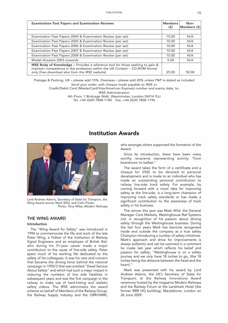
Lord Andrew Adonis, Secretary of State for Transport, theWing Award winner Mark Wild, and Colin Porter.
Photo: Tony Miles, Modern Railways
THE WING AWARDIntroduction
The "Wing Award for Safety" was introduced in1994 to commemorate the life and work of the latePeter Wing, a Fellow of the Institution of RailwaySignal Engineers and an employee of British Rail,who during his 31-year career made a majorcontribution to the cause of line-side safety. Peterspent much of his working life dedicated to thesafety of his colleagues. It was his care and concernthat became the driving force behind the nationalcampaign in 1992/3 that was entitled “Dead SeriousAbout Safety” and which had such a major impact inreducing the numbers of line side fatalities insubsequent years and was the first campaign in therailway to make use of hard-hitting and realisticsafety videos. The IRSE administers the awardscheme on behalf of Members of the Railway Group,the Railway Supply Industry and the ORR/HMRI,
who amongst others supported the formation of theAward.
Since its introduction, there have been manyworthy recipients representing activity “fromboardroom to ballast.”
The award takes the form of a certificate and acheque for £500 to be devoted to personaldevelopment and is made to an individual who hasmade an outstanding personal contribution torailway line-side track safety. For example, bycoming forward with a novel idea for improvingsafety at the line-side, is a long-term champion ofimproving track safety standards or has made asignificant contribution to the awareness of tracksafety in his business.
The winner this year was Mark Wild, the GeneralManager Core Markets, Westinghouse Rail SystemsLtd. in recognition of his passion about drivingsafety through the Westinghouse business. Duringthe last four years Mark has become recognisedinside and outside the company as a true safetyChampion introducing a number of safety initiatives.Mark’s approach and drive for improvements isalways authentic and can be summed in a commenthe made last year which reflects his belief andpassion for safety; "Westinghouse is on a safetyjourney and we only have 18 inches to go, (the 18inches being the distance between the head and theheart).”
Mark was presented with his award by LordAndrew Adonis, the UK’s Secretary of State forTransport, at the Railway Innovations Awardceremony hosted by the magazine Modern Railwaysand the Railway Forum at the Landmark Hotel (theformer BRB HQ building), Marylebone, London on26 June 2009.
16
Previous Winners
Previous winners of the Wing Award have been;
1995 R Dickinson BR1996 W Hill Amec1997 I Keys LUL1998 R Hickman Centrac1999 A Ross LUL2000 A Franklin GTRM2001 P Graham Railtrack2002 A Swann Safety Consultant2003 A Nelson Railway Safety2004 B West Amey Rail2005 P Broad Network Rail2006 C Wheeler Railstaff2007 C Bickerstaffe 4x32008 S Cassidy Network Rail
Colin Porter
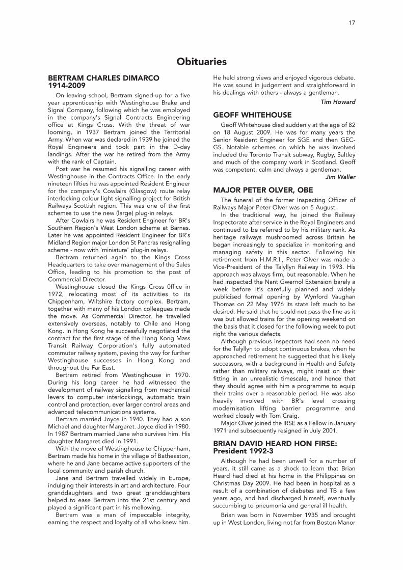
DELL AWARDThe winner of the Dell Award 2010 was Peter
Clifford from Tube Lines Ltd. The Dell award is madeannually under a bequest of the late Robert DellOBE (Past President) and is awarded to a member ofthe Institution employed by London UndergroundLtd or one of its successor companies forachievement of a high standard of skill in the scienceand application of Railway signalling. The awardtakes the form of a plaque with a uniquely designedshield being added each year with the recipient’sname engraved on it and a cheque for £300 tospend as the recipient wishes.
courses and at one time running a study group forprospective IRSE Exam candidates. He was also oneof LU’s first IRSE licensing assessors, and continuesto administer internal, asset-based licences. Since2005, Peter had been the Signalling Lead DisciplineEngineer for the Victoria Line Upgrade. Of note,Peter jointly authored a technical paper entitled‘Implementing the Victoria Line Signalling Overlay’that was presented to the IRSE London meeting inFebruary 2009.
INSTITUTION AWARDS
2010 Dell Award winner, Peter Clifford being presentedwith the award by the President, Frans Heijnen at theAGM on 23 April 2010
Photo Ken Burrage
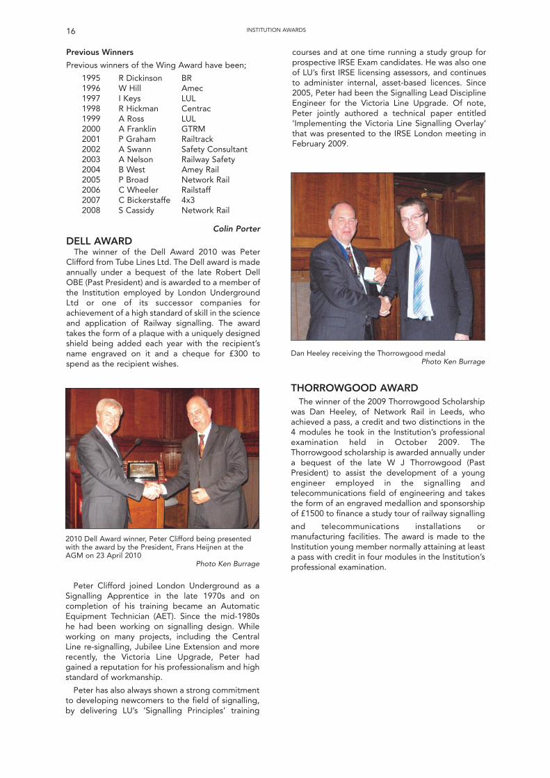
Dan Heeley receiving the Thorrowgood medalPhoto Ken Burrage
Peter Clifford joined London Underground as aSignalling Apprentice in the late 1970s and oncompletion of his training became an AutomaticEquipment Technician (AET). Since the mid-1980she had been working on signalling design. Whileworking on many projects, including the CentralLine re-signalling, Jubilee Line Extension and morerecently, the Victoria Line Upgrade, Peter hadgained a reputation for his professionalism and highstandard of workmanship.
Peter has also always shown a strong commitmentto developing newcomers to the field of signalling,by delivering LU’s ‘Signalling Principles’ training
THORROWGOOD AWARDThe winner of the 2009 Thorrowgood Scholarship
was Dan Heeley, of Network Rail in Leeds, whoachieved a pass, a credit and two distinctions in the4 modules he took in the Institution’s professionalexamination held in October 2009. TheThorrowgood scholarship is awarded annually undera bequest of the late W J Thorrowgood (PastPresident) to assist the development of a youngengineer employed in the signalling andtelecommunications field of engineering and takesthe form of an engraved medallion and sponsorshipof £1500 to finance a study tour of railway signalling
and telecommunications installations ormanufacturing facilities. The award is made to theInstitution young member normally attaining at leasta pass with credit in four modules in the Institution’sprofessional examination.
17
BERTRAM CHARLES DIMARCO 1914-2009
On leaving school, Bertram signed-up for a fiveyear apprenticeship with Westinghouse Brake andSignal Company, following which he was employedin the company's Signal Contracts Engineeringoffice at Kings Cross. With the threat of warlooming, in 1937 Bertram joined the TerritorialArmy. When war was declared in 1939 he joined theRoyal Engineers and took part in the D-daylandings. After the war he retired from the Armywith the rank of Captain.
Post war he resumed his signalling career withWestinghouse in the Contracts Office. In the earlynineteen fifties he was appointed Resident Engineerfor the company's Cowlairs (Glasgow) route relayinterlocking colour light signalling project for BritishRailways Scottish region. This was one of the firstschemes to use the new (large) plug-in relays.
After Cowlairs he was Resident Engineer for BR'sSouthern Region's West London scheme at Barnes.Later he was appointed Resident Engineer for BR'sMidland Region major London St Pancras resignallingscheme - now with 'miniature' plug-in relays.
Bertram returned again to the Kings CrossHeadquarters to take over management of the SalesOffice, leading to his promotion to the post ofCommercial Director.
Westinghouse closed the Kings Cross 0ffice in1972, relocating most of its activities to itsChippenham, Wiltshire factory complex. Bertram,together with many of his London colleagues madethe move. As Commercial Director, he travelledextensively overseas, notably to Chile and HongKong. In Hong Kong he successfully negotiated thecontract for the first stage of the Hong Kong MassTransit Railway Corporation's fully automatedcommuter railway system, paving the way for furtherWestinghouse successes in Hong Kong andthroughout the Far East.
Bertram retired from Westinghouse in 1970.During his long career he had witnessed thedevelopment of railway signalling from mechanicallevers to computer interlockings, automatic traincontrol and protection, ever larger control areas andadvanced telecommunications systems.
Bertram married Joyce in 1940. They had a sonMichael and daughter Margaret. Joyce died in 1980.In 1987 Bertram married Jane who survives him. Hisdaughter Margaret died in 1991.
With the move of Westinghouse to Chippenham,Bertram made his home in the village of Batheaston,where he and Jane became active supporters of thelocal community and parish church.
Jane and Bertram travelled widely in Europe,indulging their interests in art and architecture. Fourgranddaughters and two great granddaughtershelped to ease Bertram into the 21st century andplayed a significant part in his mellowing.
Bertram was a man of impeccable integrity,earning the respect and loyalty of all who knew him.
He held strong views and enjoyed vigorous debate.He was sound in judgement and straightforward inhis dealings with others - always a gentleman.
Tim Howard
GEOFF WHITEHOUSEGeoff Whitehouse died suddenly at the age of 82
on 18 August 2009. He was for many years theSenior Resident Engineer for SGE and then GEC-GS. Notable schemes on which he was involvedincluded the Toronto Transit subway, Rugby, Saltleyand much of the company work in Scotland. Geoffwas competent, calm and always a gentleman.
Jim Waller
MAJOR PETER OLVER, OBEThe funeral of the former Inspecting Officer of
Railways Major Peter Olver was on 5 August.In the traditional way, he joined the Railway
Inspectorate after service in the Royal Engineers andcontinued to be referred to by his military rank. Asheritage railways mushroomed across Britain hebegan increasingly to specialize in monitoring andmanaging safety in this sector. Following hisretirement from H.M.R.I., Peter Olver was made aVice-President of the Talyllyn Railway in 1993. Hisapproach was always firm, but reasonable. When hehad inspected the Nant Gwernol Extension barely aweek before it’s carefully planned and widelypublicised formal opening by Wynford VaughanThomas on 22 May 1976 its state left much to bedesired. He said that he could not pass the line as itwas but allowed trains for the opening weekend onthe basis that it closed for the following week to putright the various defects.
Although previous inspectors had seen no needfor the Talyllyn to adopt continuous brakes, when heapproached retirement he suggested that his likelysuccessors, with a background in Health and Safetyrather than military railways, might insist on theirfitting in an unrealistic timescale, and hence thatthey should agree with him a programme to equiptheir trains over a reasonable period. He was alsoheavily involved with BR's level crossingmodernisation lifting barrier programme andworked closely with Tom Craig.
Major Olver joined the IRSE as a Fellow in January1971 and subsequently resigned in July 2001.
BRIAN DAVID HEARD HON FIRSE:President 1992-3
Although he had been unwell for a number ofyears, it still came as a shock to learn that BrianHeard had died at his home in the Philippines onChristmas Day 2009. He had been in hospital as aresult of a combination of diabetes and TB a fewyears ago, and had discharged himself, eventuallysuccumbing to pneumonia and general ill health.
Brian was born in November 1935 and broughtup in West London, living not far from Boston Manor
Obituaries
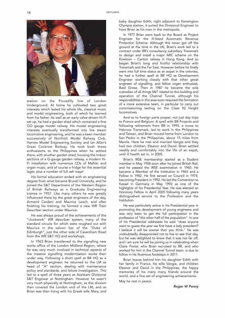
station on the Piccadilly line of LondonUnderground. At home he cultivated two greatinterests which lasted his whole life, classical musicand model engineering, both of which he learnedfrom his father. As well as an early valve-driven Hi-Fiset up, he had a garden shed which contained a fineOO gauge model railway. His model engineeringinterests eventually transformed into live steamlocomotive engineering, and he was a keen membersuccessively of Northolt Model Railway Club,Harrow Model Engineering Society and Ian Allan’sGreat Cockrow Railway. He took both theseenthusiasms to the Philippines when he settledthere, with another garden shed, housing the indoorsections of a G-gauge garden railway, a modern Hi-Fi installation with numerous CDs of Mahler andorgan music, and of course a fridge for the essentiallager, plus a number of full ash trays!
His formal education ended with an engineeringdegree from what became Brunel University, and hejoined the S&T Department of the Western Regionof British Railways as a Graduate Engineeringtrainee in 1957. Like many others he was greatlyinfluenced there by the great engineers of the day,Armand Cardani and Maurice Leach, and afterfinishing his training, he formed a new WR TrainDescriber section under Maurice.
He was always proud of the achievements of the“clockwork” WR describer system, many of thestandard circuits for which were roughed out withMaurice in the saloon bar of the “Duke ofEdinburgh”, just the other side of Caversham Roadfrom the WR S&T HQ and workshops.
In 1963 Brian transferred to the signalling newworks office of the London Midland Region, wherehe was very much involved in technical aspects ofthe massive signalling modernisation works thenunder way. Following a short spell at BR HQ as adevelopment engineer, he returned to the LM ashead of “A” section, dealing with maintenancepolicy and standards, and failure investigation. Thisled to a spell of three years as Assistant DivisionalS&T Engineer at Nottingham. However he wasn’tvery much physically at Nottingham, as this divisionthen covered the London end of the LM, and asBrian was then living with his Greek wife Mary, and
baby daughter Edith, right adjacent to KensingtonOlympia station, it suited the Divisional Engineer tohave Brian as his man in the metropolis.
In 1977 Brian went back to the Board as ProjectEngineer for the ill-fated Automatic RevenueProtection Scheme. Although this never got off theground at the time in the UK, Brian’s work led to acontract under BR’s consultancy subsidiary Transmarkto design and install a major ARC scheme on theKowloon – Canton railway in Hong Kong. And sobegan Brian’s long and fruitful relationship withTransmark and the Far East. However before he finallywent into full time status as an expat in the colonies,he had a further spell at BR HQ as DevelopmentEngineer working closely with that other greatengineer of signalling, and fellow organ enthusiast,Basil Grose. Then in 1987 he became the solecustodian of all things S&T related to the building andoperation of the Channel Tunnel, although hisresponsibilities in this area soon required the formationof a more extensive team, in particular to carry outcommissioning testing on the Class 92 freightlocomotives.
And so to foreign parts proper, not just day tripsto France and Belgium. A spell with BR Projects andfollowing retirement from BR in 1995, a move toHalcrow Transmark, led to work in the Philippinesand Taiwan, and Brian moved home from London toSan Pedro in the Philippines, about 15 miles fromManila. Here he met and married Vangie and theyhad two children, Eleanor and David. Brian settledreadily and comfortably into the life of an expat,until ill health set in, in 2005.
Brian’s IRSE membership started as a Studentmember in May 1958 soon after he joined British Rail,and he passed the IRSE examination in 1960. Hebecame a Member of the Institution in 1965 and aFellow in 1982. He first served on Council in 1974,becoming President in 1992. He led the Convention toKassel in Germany in May 1992 as one of thehighlights of his Presidential Year. He was elected anHonorary Fellow in April 2005 following many yearsdistinguished service to the Profession and theInstitution.
He was particularly active in his Presidential year inpromoting the development of young engineers andwas very keen to get the full participation in theprofession of “the other half of the population”. In oneof his Presidential addresses he said “does anyonewant to guess the year we first have a lady president?I believe it will be sooner than you think.” He wasundoubtedly disappointed not to live to see that day,but he was delighted to know that it was not far off,and I am sure he will be joining us in celebrating whenClaire Porter, who Brian recruited to BR, and whoworked for him in the Channel Tunnel team, is due tofollow in his illustrious footsteps in 2011.
Brian leaves behind him his daughter Edith withher family in France, his wife Vangie, and childrenEleanor and David in the Philippines, the happymemories of his many many friends around theworld, and a fine set of engineering achievements.
May he rest in peace.
Roger W Penny
18 OBITUARIES
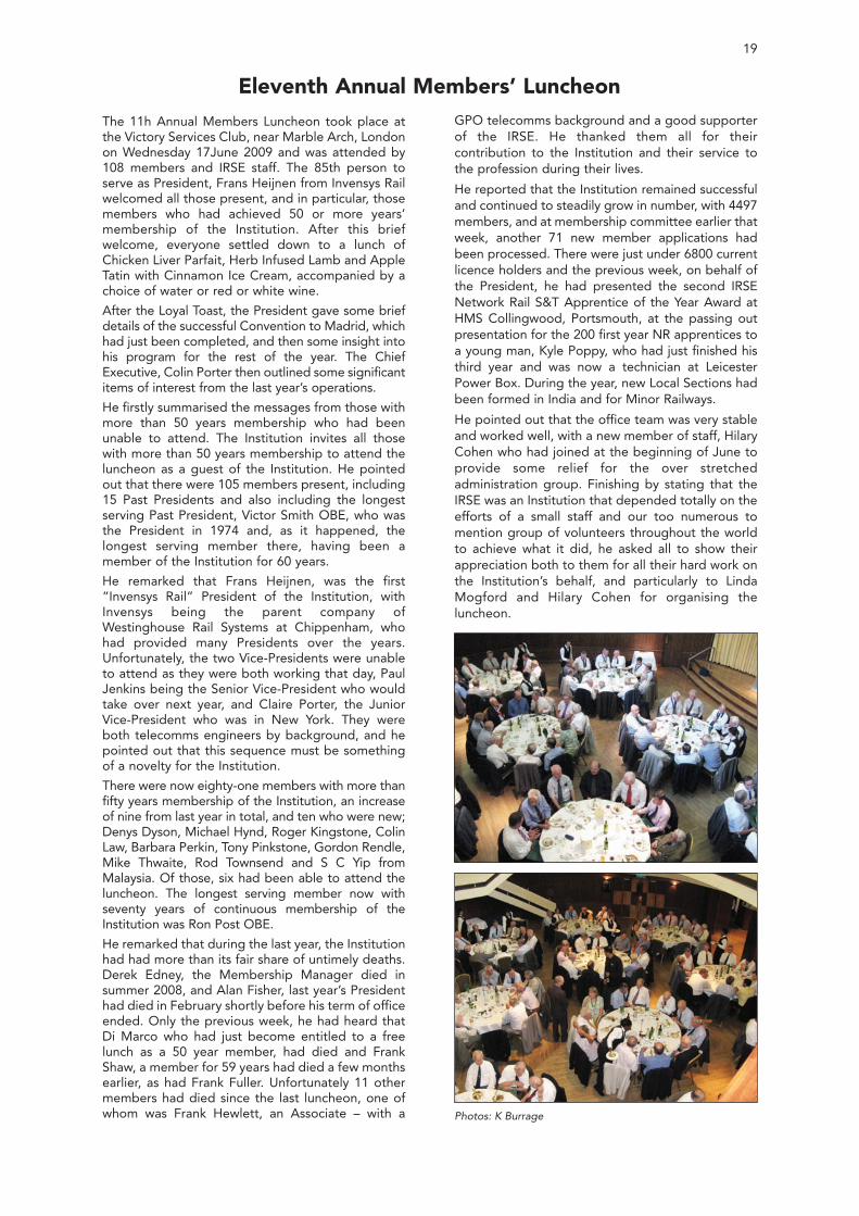
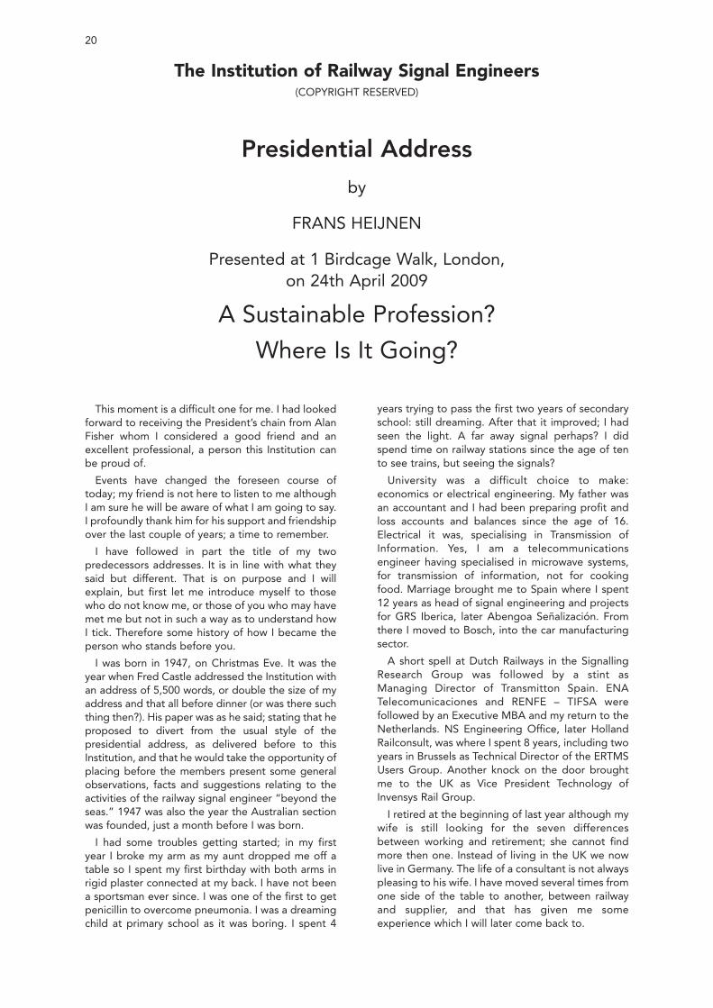
The 11h Annual Members Luncheon took place atthe Victory Services Club, near Marble Arch, Londonon Wednesday 17June 2009 and was attended by108 members and IRSE staff. The 85th person toserve as President, Frans Heijnen from Invensys Railwelcomed all those present, and in particular, thosemembers who had achieved 50 or more years’membership of the Institution. After this briefwelcome, everyone settled down to a lunch ofChicken Liver Parfait, Herb Infused Lamb and AppleTatin with Cinnamon Ice Cream, accompanied by achoice of water or red or white wine.
After the Loyal Toast, the President gave some briefdetails of the successful Convention to Madrid, whichhad just been completed, and then some insight intohis program for the rest of the year. The ChiefExecutive, Colin Porter then outlined some significantitems of interest from the last year’s operations.
He firstly summarised the messages from those withmore than 50 years membership who had beenunable to attend. The Institution invites all thosewith more than 50 years membership to attend theluncheon as a guest of the Institution. He pointedout that there were 105 members present, including15 Past Presidents and also including the longestserving Past President, Victor Smith OBE, who wasthe President in 1974 and, as it happened, thelongest serving member there, having been amember of the Institution for 60 years.
He remarked that Frans Heijnen, was the first“Invensys Rail” President of the Institution, withInvensys being the parent company ofWestinghouse Rail Systems at Chippenham, whohad provided many Presidents over the years.Unfortunately, the two Vice-Presidents were unableto attend as they were both working that day, PaulJenkins being the Senior Vice-President who wouldtake over next year, and Claire Porter, the JuniorVice-President who was in New York. They wereboth telecomms engineers by background, and hepointed out that this sequence must be somethingof a novelty for the Institution.
There were now eighty-one members with more thanfifty years membership of the Institution, an increaseof nine from last year in total, and ten who were new;Denys Dyson, Michael Hynd, Roger Kingstone, ColinLaw, Barbara Perkin, Tony Pinkstone, Gordon Rendle,Mike Thwaite, Rod Townsend and S C Yip fromMalaysia. Of those, six had been able to attend theluncheon. The longest serving member now withseventy years of continuous membership of theInstitution was Ron Post OBE.
He remarked that during the last year, the Institutionhad had more than its fair share of untimely deaths.Derek Edney, the Membership Manager died insummer 2008, and Alan Fisher, last year’s Presidenthad died in February shortly before his term of officeended. Only the previous week, he had heard thatDi Marco who had just become entitled to a freelunch as a 50 year member, had died and FrankShaw, a member for 59 years had died a few monthsearlier, as had Frank Fuller. Unfortunately 11 othermembers had died since the last luncheon, one ofwhom was Frank Hewlett, an Associate – with a
GPO telecomms background and a good supporterof the IRSE. He thanked them all for theircontribution to the Institution and their service tothe profession during their lives.
He reported that the Institution remained successfuland continued to steadily grow in number, with 4497members, and at membership committee earlier thatweek, another 71 new member applications hadbeen processed. There were just under 6800 currentlicence holders and the previous week, on behalf ofthe President, he had presented the second IRSENetwork Rail S&T Apprentice of the Year Award atHMS Collingwood, Portsmouth, at the passing outpresentation for the 200 first year NR apprentices toa young man, Kyle Poppy, who had just finished histhird year and was now a technician at LeicesterPower Box. During the year, new Local Sections hadbeen formed in India and for Minor Railways.
He pointed out that the office team was very stableand worked well, with a new member of staff, HilaryCohen who had joined at the beginning of June toprovide some relief for the over stretchedadministration group. Finishing by stating that theIRSE was an Institution that depended totally on theefforts of a small staff and our too numerous tomention group of volunteers throughout the worldto achieve what it did, he asked all to show theirappreciation both to them for all their hard work onthe Institution’s behalf, and particularly to LindaMogford and Hilary Cohen for organising theluncheon.
19
Eleventh Annual Members’ Luncheon
Photos: K Burrage
This moment is a difficult one for me. I had lookedforward to receiving the President’s chain from AlanFisher whom I considered a good friend and anexcellent professional, a person this Institution canbe proud of.
Events have changed the foreseen course oftoday; my friend is not here to listen to me althoughI am sure he will be aware of what I am going to say.I profoundly thank him for his support and friendshipover the last couple of years; a time to remember.
I have followed in part the title of my twopredecessors addresses. It is in line with what theysaid but different. That is on purpose and I willexplain, but first let me introduce myself to thosewho do not know me, or those of you who may havemet me but not in such a way as to understand howI tick. Therefore some history of how I became theperson who stands before you.
I was born in 1947, on Christmas Eve. It was theyear when Fred Castle addressed the Institution withan address of 5,500 words, or double the size of myaddress and that all before dinner (or was there suchthing then?). His paper was as he said; stating that heproposed to divert from the usual style of thepresidential address, as delivered before to thisInstitution, and that he would take the opportunity ofplacing before the members present some generalobservations, facts and suggestions relating to theactivities of the railway signal engineer “beyond theseas.” 1947 was also the year the Australian sectionwas founded, just a month before I was born.
I had some troubles getting started; in my firstyear I broke my arm as my aunt dropped me off atable so I spent my first birthday with both arms inrigid plaster connected at my back. I have not beena sportsman ever since. I was one of the first to getpenicillin to overcome pneumonia. I was a dreamingchild at primary school as it was boring. I spent 4
years trying to pass the first two years of secondaryschool: still dreaming. After that it improved; I hadseen the light. A far away signal perhaps? I didspend time on railway stations since the age of tento see trains, but seeing the signals?
University was a difficult choice to make:economics or electrical engineering. My father wasan accountant and I had been preparing profit andloss accounts and balances since the age of 16.Electrical it was, specialising in Transmission ofInformation. Yes, I am a telecommunicationsengineer having specialised in microwave systems,for transmission of information, not for cookingfood. Marriage brought me to Spain where I spent12 years as head of signal engineering and projectsfor GRS Iberica, later Abengoa Señalización. Fromthere I moved to Bosch, into the car manufacturingsector.
A short spell at Dutch Railways in the SignallingResearch Group was followed by a stint asManaging Director of Transmitton Spain. ENATelecomunicaciones and RENFE – TIFSA werefollowed by an Executive MBA and my return to theNetherlands. NS Engineering Office, later HollandRailconsult, was where I spent 8 years, including twoyears in Brussels as Technical Director of the ERTMSUsers Group. Another knock on the door broughtme to the UK as Vice President Technology ofInvensys Rail Group.
I retired at the beginning of last year although mywife is still looking for the seven differencesbetween working and retirement; she cannot findmore then one. Instead of living in the UK we nowlive in Germany. The life of a consultant is not alwayspleasing to his wife. I have moved several times fromone side of the table to another, between railwayand supplier, and that has given me someexperience which I will later come back to.
20
The Institution of Railway Signal Engineers(COPYRIGHT RESERVED)
Presidential Address
by
FRANS HEIJNEN
Presented at 1 Birdcage Walk, London,on 24th April 2009
A Sustainable Profession?
Where Is It Going?
THEME OF MY YEARAs I said before, the theme is somewhat different
from Wim Coenraad’s theme and Alan Fisher’ssequel. I did not want it to become like Star Wars soI decided to focus on the people in the profession asthey are the living things in this profession.
First I would like to say that people were not mypassion in my youth, being rather introvert, but overthe years I have recognised that working with peopleand interrelating with them is much more gratifyingthan any engineering wonder. The profession is aninteraction of people; it is the people that make thestuff and not the other way around.
Secondly, I do like technology but I am not a“techie” in that sense. Technology is important butit must serve a purpose. The required functionalityto support a process is what we are trying toimplement; the technology brings that into reality asbest as it can. Being an engineer myself I dounderstand the pitfalls of our profession: put twoengineers in a room and you will get two newsolutions, put three in a room and you will get six. Iwill leave it to the mathematicians amongst you towork out what will happen if you put four in a room.
The engineering profession is about analysing theproblem, investigating the possible solutions andrecommending the way to go. This process is whatshould be taught at engineering school, not justpure factual knowledge as I have seen on too manyoccasions. A reflection on the current status of ourprofession indicates to me that we have created alot of silos. The break up of the railways due to theEuropean Railway Directive has certainly played arole in this. The split between InfrastructureManagers and Railway Undertakings was intendedbut seeing the UK panorama, one sometimeswonders how on earth this complex “patchwork”still allows the trains to run. At the same time therehas been created a drive for cost reduction as manyof these entities were set profitability targets;targets that forced them to rethink every expense.Training was an obvious victim, maybe not intendedbut nevertheless we can now see the results. Thepeople now working in the railway environment findthemselves working for only a part of the system.They work for Roscos, civil contractors, regulators,to name a few; not anymore for a single entity wherebosses and coaches could move them around withina single railway organisation. That gave themexperience of all the different aspects of the railwayprocess or organisation.
For the signalling profession this also had animpact but there were other drivers for this.Research was in the past very much located withinthe railway. Not in all cases but BR Research hadparallels in other countries. This has now mostlydisappeared and what is left does not have in manycases the critical mass to sustain itself. Signallingresearch has moved to the suppliers and consultantswhen it comes to equipment and products.Functionality research now sometimes takes place atEU level, if it takes place at all.
Within each entity, infrastructure manager,supplier or consultant, we have also seen a big
squeeze. Shareholders are demanding returnswithin a very short period. Whatever we do todevelop new products, systems or technologies is ofa relatively low interest to them. We need money forresearch now and when asked, we tell them that thereturns will come within 5 to 7 years. You can clearlyunderstand that this will fall on deaf ears due to theenormous mismatch of timescales; years versusmonths. Another phenomenon to consider is theage profile of our professionals that many timesmatches that of the railway. Influx of new employeescomes in waves and as such people retire in waves ifnot pushed out earlier due to cost reductions. Thebaby boomers, and I am one of them, are retiringright now and with them a lot of general and specificknowledge will leave the sector. This wave seems tobe somewhat universal in Western society. It ispositive for the people who retire but it creates aproblem for the system. The people involved havebeen there in many cases for a long time and theymay be the last generation of lifetime railwaypeople when it comes to our part of the system.
We should also not forget the influence of rulesand regulations on our sector. CENELEC and allother such standards have created a need for veryspecialised people, in many occasions hired fromother sectors like the aviation or process industry.These people enter our sector to perform a certaintask and then leave the sector again as their skillsare also useful elsewhere. Combine this with theimage of our sector and you can see a problem.Software is core to our products and systemsnowadays but a software engineer is not necessarilyinterested in the functionality his work creates, sothe bond with the sector is weak. We havecompartmentalised signal engineering into clearlydemarcated jobs. We have designers, developers,software writers, testers, maintainers etc. Peoplewho do a great job but who do not have thechanges in their career path that previousgenerations had, at a time when the systems andprocesses were less complex and more accessible.
My theory is that we are losing the oversight of ourtrade. Too few people are rotated through differentjobs and positions in the trade to allow them to formthat overview. Even in my own career, although itwas not planned, I had 12 jobs luckily not followedby 13 accidents as we say in the Netherlands, whichdid give me a platform of diversity from which toobserve the different facets of the industry. To seedifferent elements of the “cradle to grave” chain ofour systems gives you an insight in the impact ofactions and decisions that were taken in previousphases. Clear examples of isolated working aredesigns that are a technical miracle but later prove tobe very difficult to implement or to maintain. Mypredecessors’ themes clearly identify some of theseissues. We should do something about this. TheInstitution is a key player when it comes to proposinga new course of action in relation to professionaldevelopment, as it is an Institution of people, not ofsystems. Therefore the Institution is well, if not best,placed to champion some activities.
One of them is within my year. A paper followedby a seminar on employment and education. But I
PRESIDENTIAL ADDRESS 21
think that is not enough. The first thing we need is acommon understanding of the situation. I may bewrong and therefore the first step is to see if myview is shared by the members. I invite all of you toreflect on my words and to tell me what you think isthe case. Without a shared view we cannot moveinternally on this, even less lead the outside world.For those of you who are holding positions in thesector where you have influence on the way we trainand grow people for more responsible positions, Iwould like to invite you to put your view forward inthe internal debate, in a seminar to be held inNovember. The younger members I would ask toreflect of what they expect in their professional lifeand how they would like to be trained and coached.I do not have the recipe for the solution needed; Iwould be happy if at the end of my year we have acommon understanding. Maybe not according theway I see it, but at least a common understanding.
I would now like to turn to what is going tohappen in meetings and other activities during thecoming year since I assume that you will flock to thisroom and other venues. It is part of what you will getfor your subscription.
ACTIVITIES DURING MY YEARI know that we like technical papers, at least that
is what we call them, but you will only get some realtechnical papers in my year.
In the October meeting here in London SteveFeatherstone of Network Rail will present a paperentitled “Maintenance, an update on the UKapproach”. This topic is more about delivering andmaintaining functionality than it is about thetechnology. You will hear some examples of theproblem I described earlier.
“Signalling, Have We Lost the Plot?” is the title ofthe November paper, presented by a Past Presidentknown to you all, Eddie Goddard of LondonUnderground. He will expand on the theme of myyear and will try to describe what we have to do totrain the people we need in this sector in the future.
The November Seminar will deepen out thistheme. The Professional Development committee ofthe Institution has volunteered to prepare thisseminar under the working title “Education andcareer paths in the Industry”.
Our autumn visit in November will take us to thenorth. Scotland has been an area of major signallingrenewals lately. Glasgow, Edinburgh and Airdrie-Bathgate, just to name a few. The final programmeis still being established but it is going to beinteresting. In December you will get a moretechnical paper from Ian Mitchell from Delta Rail. Hispaper, entitled “Sustainable Railway: use of advisorysystems for energy savings”, will describe howtechnology can add a functionality to our systemsthat helps to reduce the environmental impact ofthe railway. But even though it is a technical paper,it is about the future of the railway and how toaddress the challenges.
The January meeting will bring a speaker from myhome country. One of my former colleagues of theDutch Railways, Jeroen Nederlof of Prorail, will
present a paper on Level Crossings in theNetherlands. Jeroen did a lot of analysis on theinfluence of layouts, visibility and other factors onthe rate of accidents on level crossings. Not abouttechnology but about the results of our work: did weprovide the best solution?
The author of the February paper works for theAustrian Frequentis. We visited this company duringthe recent Technical Visit in Vienna. This paper willprovide a comparison on control room managementin different sectors, with the title: “Are Rail and Airso different” and it will be given by Gottfried Almer.Is this telecomms or is this signalling functionality?You can decide after listening to the paper.
In February we will organise a seminar on acurrent research project funded by the EuropeanUnion together with 36 entities from the sector.INESS is about defining the functionality and thearchitecture of future signalling systems and by thetime of the seminar the project will be almosthalfway. History and impact of the planned outcomeof the project are the key topics.
Our spring technical visit is to Wildenrath inGermany. It is near to where I live in the Aachenarea. Established on a former British Airbase theRegional Government of Nord Rhein Westfalen, ithas helped Siemens to establish one of the mostsophisticated test tracks available in the world.Other parts of the visit are bring us to the AachenHauptbahnhof recent interlocking renewal. AsAachen is near by measured from London, as well asthe Ardennes and the Eiffel mountains, it is a goodoccasion for a weekend away, only four hours awayby train. The new High Speed line between Liegeand Aachen will be operational under ETCS Level 2by then.
The March session will see a paper on the 2010Convention. I am not going to disclose where it willbe held so you will get no title here.
THE 2009 CONVENTIONAs you will have gathered by now, Spain played an
important part in my professional career. It istherefore with pleasure that I invite you to join meon a convention in Spain, during the last week ofMay. It will be the fourth occasion that we havevisited Spain. 1970 saw Mr Cardani, a well knownPresident, lead a party of 70 UK Members andGuests, joined by a further 27 overseas members.They visited Madrid Chamartín, Burgos, Segoviaand Metro Madrid. Some interesting names on thediners list: Luis Urquí whom I met while working atAbengoa in 1975, and a certain Mr Martinez whomust have been very young then. José retired someyears ago as my colleague. He was the President ofDimetronic Signals then, having been President andCEO of BTR Rail, the predecessor of the InvensysRail Group. Maybe organising a convention is theway to become a big shot in signalling world.
1984 was the year I attended my first conventionas a brand new Institution member. Starting inBarcelona and ending in Madrid, this conventionwas led by David Norton of Westinghouse. Therewere visits to Segovia, Miranda and El Escorial for
PRESIDENTIAL ADDRESS22
the guests and Sants in Barcelona, Chamartín andthe Metro in Madrid for the members. The last twowere a repeat of the 1970 convention and we willsee them again this year. As was said in theproceedings of the 1995 Summer Convention, it wasthird time lucky. 1970 had seen snow, 1984 was coldand wet but Eddie Goddard and his 300 fellowdelegates had a lot of sunshine. Some of you will stillremember the burn out we had seeing the horses onthe Sevilla Ranch after our run with the High SpeedTrain to Seville. We saw also Metro de Madrid, butnot Chamartín that time; Toledo was part of theprogramme.
This year we will show you a full-grown HighSpeed Network. Madrid to Seville was 472kilometres long and signalled with LZB but nowRENFE has 2,000 kilometres in service or underconstruction with commercial speeds up to 320kph.The theme is ERTMS ETCS for most of theconvention, as this is a topic I have been involved infor 12 years now. On the Tuesday we will give you anupdate on Chamartín where Alstom is installing anew interlocking and we will show you the new HighSpeed line to Segovia and Valladolid with its longtunnel under the Guardarama mountain range. Yourpartners will be close by as they will be visitingSegovia. Wednesday will see all of us in Toledo, fora renewed visit to the city. Thursday will bring you toZaragoza. Friday the update of Metro de Madrid,where the latest in Mass Transit land, CBTC, will be
shown to you. The Dinner on Friday will finish in theearly morning hours so bring your dancing shoeswith you. This means that the convention will end onSaturday, at around 01:30.
CONCLUSIONI am afraid you will have to cope with another
Dutchman for a year having had Wim Coenraad asthe President in 2007-8. So close are our culturesbut sometimes so different. Nevertheless, I hopenot to disappoint you this year, by setting aprogramme that deals with the challenges on ourway into the future. I have tried to accommodate inthe programme for the London papers and for theTechnical Visits and Seminars the preferences ofmany members, however different these are, but Ihope that in the end you will recognise my biggestworry: are we prepared for the future?
I hope that after a year serving you we will havethis on our radar and that initiatives to address thisissue are on our roadmap. As I said in the beginningof my speech, this is not a direct sequel of mypredecessors’ work but it goes in the samedirection: the world is changing and, whether welike it or not, it will do so without asking us forpermission. Our sector is perceived as being slow inits responses; let us pre-empt the future this time.
Thank you
Frans Heijnen
PRESIDENTIAL ADDRESS 23
24
Technical Meeting of the Institutionheld at
1 Birdcage Walk, London
Wednesday 14th October 2009The President, Mr F Heijnen, in the chair.
106 members and visitors were in attendance. There was an apology for absence from David McKeown. It was proposed by Mr R Penny, seconded by Mr M Govas and carried that the minutes of the
technical meeting held on 11 March 2009 be taken as read and they were signed by Mr Heijnen as a correct record. The Chairman then invited any new members present for the first time since their election to come forward to be introduced to the meeting. Mr Paul
Armstrong (Network Rail) and Mr Paul Jenkins (Achilles) came forward to be introduced to warm applause. The Chairman then introduced Steve Featherstone (Director of Infrastructure Maintenance of Network Rail) and asked him to present his paper
“Maintenance – An Update on the Network Rail Approach.”Mr Featherstone started by describing the financial challenges presented by the target costs laid down for the control period 4 by the ORR. He stated that
track worker safety was of paramount importance, and that overall failure performance of the railway was improving steadily. He described the processimprovement initiatives taking place, including “copy with pride”, an initiative for spreading best practice, the increasing use of reliability centred maintenanceand the implications of the “7 day railway” project. Increasing use was being made of specialist inspection trains, and even service trains fitted with monitoringequipment, and the NR helicopter was being used for aerial surveys. He concluded by highlighting the significant intake of apprentices in the last four years,and the maintenance restructuring that was currently being consulted upon. The planned reorganisation would also be subject to a safety validation process.Following the presentation, the discussion was opened by Jacques Poré (Alstom – Past President). Francis How (RIA), Ron Skillet (LUL), Peter Woodbridge(Invensys), Frans Heijnen (President), Colin Porter (Past President), Phil Bartlett (Booz & Co), Buddhadev Dutta-Chowdhury (Bombardier) and Gab Parris (LUL)all took part in the discussion.
The Chairman then thanked the speaker and proposed a vote of thanks to him for providing an interesting insight to the current plans for reorganisation ofthe management of maintenance on Network Rail. He then presented him with a commemorative plaque customarily awarded to the author of a London paper.Mr Heijnen thanked members and visitors for their attendance and their contribution, and then closed the meeting at 1930 by reminding those present aboutthe technical visit to Scotland on 20/21 November, and a seminar on 24 November in London. He announced that the next meeting in London would be atechnical meeting held on the 11 November 2009 when Mr Goddard would present a paper entitled “Signalling – Have We Lost the Plot?”
Maintenance: An Update on the Network RailApproach
Steve Featherstone1
INTRODUCTIONNetwork Rail has recently agreed its funding for
the next five years with the Office of Rail Regulation(ORR). This level of funding challenges us to bemore efficient in the way we carry out ourmaintenance activities, making our resources gofurther whilst increasing the outputs required to bedelivered. We must build upon our success over thepast five years in improving safety and trainperformance whilst significantly reducing costs. It istherefore appropriate at this time to review and toshare how Network Rail intends to maintain therailway assets within our stewardship.
This paper presents an overview of our approachto this task over the coming years. It necessarilyincludes topics that are not directly related totechnical aspects of our signalling infrastructure, asthere are many factors that influence what we do,when we do it and how we do it. The papertherefore includes sections on Network Rail’s peopleand how we organise and manage them to maintaina safe, efficient and reliable railway.
THE CP4 CHALLENGEThe challenges ahead are shaping Network Rail’s
approach to maintenance. Control Period 4 (CP4)
runs from April 2009 to March 2014. In March thisyear Network Rail accepted the determinations ofthe Office of Rail Regulation (ORR) for the fundingand outputs for CP4. We are now committed todelivering the required outputs within the fundingavailable, without compromising safety and in asustainable way.
We have already delivered significant improvementsduring the previous five year control period as follows.
• Train performance was improved from 81.2% to90.6% by Public Performance Measure, that isthe percentage of trains arriving on time at theirfinal destination.
• Incidents causing delay were reduced by 20%.
• Delay minutes were reduced by 50%.
• Asset condition was improved.
• 33% more trains now run on the network.
• This has all been achieved at the same time as areduction in costs of 26%.
We must now build on the significant businessimprovements we have made over the past fiveyears. The outputs we will deliver during CP4 are asfollows, and are summarised in Figure 1.
A HIGHLY RELIABLE RAILWAY
Plans have been developed jointly with ourcustomers to achieve a Public Performance Measureof 92.6% by April 2014. 1 Director, Infrastructure Maintenance with Network Rail.
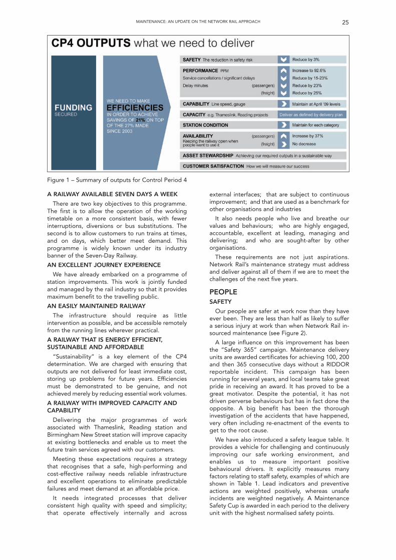
MAINTENANCE: AN UPDATE ON THE NETWORK RAIL APPROACH 25
A RAILWAY AVAILABLE SEVEN DAYS A WEEK
There are two key objectives to this programme.The first is to allow the operation of the workingtimetable on a more consistent basis, with fewerinterruptions, diversions or bus substitutions. Thesecond is to allow customers to run trains at times,and on days, which better meet demand. Thisprogramme is widely known under its industrybanner of the Seven-Day Railway.
AN EXCELLENT JOURNEY EXPERIENCE
We have already embarked on a programme ofstation improvements. This work is jointly fundedand managed by the rail industry so that it providesmaximum benefit to the travelling public.
AN EASILY MAINTAINED RAILWAY
The infrastructure should require as littleintervention as possible, and be accessible remotelyfrom the running lines wherever practical.
A RAILWAY THAT IS ENERGY EFFICIENT,SUSTAINABLE AND AFFORDABLE
“Sustainability” is a key element of the CP4determination. We are charged with ensuring thatoutputs are not delivered for least immediate cost,storing up problems for future years. Efficienciesmust be demonstrated to be genuine, and notachieved merely by reducing essential work volumes.
A RAILWAY WITH IMPROVED CAPACITY ANDCAPABILITY
Delivering the major programmes of workassociated with Thameslink, Reading station andBirmingham New Street station will improve capacityat existing bottlenecks and enable us to meet thefuture train services agreed with our customers.
Meeting these expectations requires a strategythat recognises that a safe, high-performing andcost-effective railway needs reliable infrastructureand excellent operations to eliminate predictablefailures and meet demand at an affordable price.
It needs integrated processes that deliverconsistent high quality with speed and simplicity;that operate effectively internally and across
external interfaces; that are subject to continuousimprovement; and that are used as a benchmark forother organisations and industries
It also needs people who live and breathe ourvalues and behaviours; who are highly engaged,accountable, excellent at leading, managing anddelivering; and who are sought-after by otherorganisations.
These requirements are not just aspirations.Network Rail’s maintenance strategy must addressand deliver against all of them if we are to meet thechallenges of the next five years.
PEOPLESAFETY
Our people are safer at work now than they haveever been. They are less than half as likely to suffera serious injury at work than when Network Rail in-sourced maintenance (see Figure 2).
A large influence on this improvement has beenthe “Safety 365” campaign. Maintenance deliveryunits are awarded certificates for achieving 100, 200and then 365 consecutive days without a RIDDORreportable incident. This campaign has beenrunning for several years, and local teams take greatpride in receiving an award. It has proved to be agreat motivator. Despite the potential, it has notdriven perverse behaviours but has in fact done theopposite. A big benefit has been the thoroughinvestigation of the accidents that have happened,very often including re-enactment of the events toget to the root cause.
We have also introduced a safety league table. Itprovides a vehicle for challenging and continuouslyimproving our safe working environment, andenables us to measure important positivebehavioural drivers. It explicitly measures manyfactors relating to staff safety, examples of which areshown in Table 1. Lead indicators and preventiveactions are weighted positively, whereas unsafeincidents are weighted negatively. A MaintenanceSafety Cup is awarded in each period to the deliveryunit with the highest normalised safety points.
Figure 1 – Summary of outputs for Control Period 4
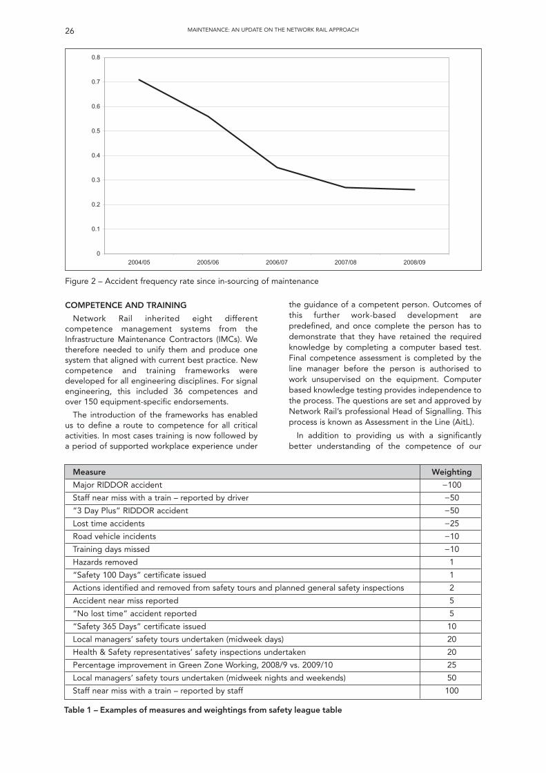
26 MAINTENANCE: AN UPDATE ON THE NETWORK RAIL APPROACH
the guidance of a competent person. Outcomes ofthis further work-based development arepredefined, and once complete the person has todemonstrate that they have retained the requiredknowledge by completing a computer based test.Final competence assessment is completed by theline manager before the person is authorised towork unsupervised on the equipment. Computerbased knowledge testing provides independence tothe process. The questions are set and approved byNetwork Rail’s professional Head of Signalling. Thisprocess is known as Assessment in the Line (AitL).
In addition to providing us with a significantlybetter understanding of the competence of our
0
0.1
0.2
0.3
0.4
0.5
0.6
0.7
0.8
2004/05 2005/06 2006/07 2007/08 2008/09
Figure 2 – Accident frequency rate since in-sourcing of maintenance
COMPETENCE AND TRAINING
Network Rail inherited eight differentcompetence management systems from theInfrastructure Maintenance Contractors (IMCs). Wetherefore needed to unify them and produce onesystem that aligned with current best practice. Newcompetence and training frameworks weredeveloped for all engineering disciplines. For signalengineering, this included 36 competences andover 150 equipment-specific endorsements.
The introduction of the frameworks has enabledus to define a route to competence for all criticalactivities. In most cases training is now followed bya period of supported workplace experience under
Measure Weighting
Major RIDDOR accident −100
Staff near miss with a train – reported by driver −50
“3 Day Plus” RIDDOR accident −50
Lost time accidents −25
Road vehicle incidents −10
Training days missed −10
Hazards removed 1
“Safety 100 Days” certificate issued 1
Actions identified and removed from safety tours and planned general safety inspections 2
Accident near miss reported 5
“No lost time” accident reported 5
“Safety 365 Days” certificate issued 10
Local managers’ safety tours undertaken (midweek days) 20
Health & Safety representatives’ safety inspections undertaken 20
Percentage improvement in Green Zone Working, 2008/9 vs. 2009/10 25
Local managers’ safety tours undertaken (midweek nights and weekends) 50
Staff near miss with a train – reported by staff 100
Table 1 – Examples of measures and weightings from safety league table
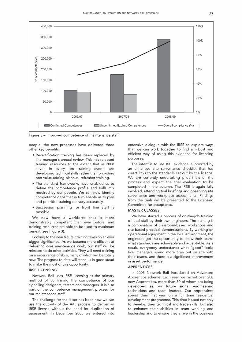
people, the new processes have delivered threeother key benefits.
• Recertification training has been replaced byline manager’s annual review. This has releasedtraining resources to the extent that in 2008seven in every ten training events aredeveloping technical skills rather than providingnon-value adding biannual refresher training.
• The standard frameworks have enabled us todefine the competence profile and skills mixrequired by our people. We can now identifycompetence gaps that in turn enable us to planand prioritise training delivery accurately.
• Succession planning for front line staff ispossible.
We now have a workforce that is moredemonstrably competent than ever before, andtraining resources are able to be used to maximumbenefit (see Figure 3).
Looking to the near future, training takes on an everbigger significance. As we become more efficient atdelivering core maintenance work, our staff will bereleased to do other activities. They will need trainingon a wider range of skills, many of which will be totallynew. The progress to date will stand us in good steadto make the most of this opportunity.
IRSE LICENSING
Network Rail uses IRSE licensing as the primarymethod of confirming the competence of oursignalling designers, testers and managers. It is alsopart of the competence management process forour maintenance staff.
The challenge for the latter has been how we canuse the outputs of the AitL process to deliver anIRSE license without the need for duplication ofassessment. In December 2008 we entered into
27MAINTENANCE: AN UPDATE ON THE NETWORK RAIL APPROACH
extensive dialogue with the IRSE to explore waysthat we can work together to find a robust andefficient way of using this evidence for licensingpurposes.
The intent is to use AitL evidence, supported byan enhanced site surveillance checklist that hasdirect links to the standards set out by the licence.We are currently undertaking pilot trials of theprocess and expect the trial evaluation to becompleted in the autumn. The IRSE is again fullyinvolved, attending trial briefings and observing sitesurveillance and workplace assessments. Findingsfrom the trials will be presented to the LicensingCommittee for acceptance.
MASTER CLASSES
We have started a process of on-the-job trainingof local staff by their own engineers. The training isa combination of classroom-based workshops andsite-based practical demonstrations. By working onoperational equipment in the local environment, theengineers get the opportunity to show their teamswhat standards are achievable and acceptable. As aresult, everybody understands what “good” lookslike, managers spend more time out on site withtheir teams, and there is a significant improvementin asset performance.
APPRENTICES
In 2005 Network Rail introduced an AdvancedApprentice scheme. Each year we recruit over 200new Apprentices, more than 80 of whom are beingdeveloped as our future signal engineeringtechnicians and team leaders. Our apprenticesspend their first year on a full time residentialdevelopment programme. This time is used not onlyto develop their technical and trade skills, but alsoto enhance their abilities in team working andleadership and to ensure they arrive in the business
0
50,000
100,000
150,000
200,000
250,000
300,000
350,000
400,000
90/800280/700270/6002
No
of c
ompe
tenc
ies
0%
20%
40%
60%
80%
100%
120%
Confirmed Competences Unconfirmed/Expired Competences Overall compliance (%)
Figure 3 – Improved competence of maintenance staff
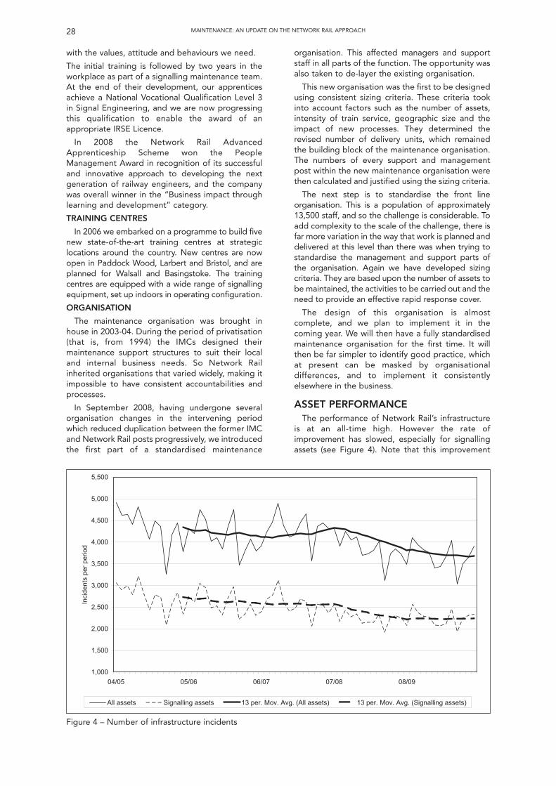
with the values, attitude and behaviours we need.
The initial training is followed by two years in theworkplace as part of a signalling maintenance team.At the end of their development, our apprenticesachieve a National Vocational Qualification Level 3in Signal Engineering, and we are now progressingthis qualification to enable the award of anappropriate IRSE Licence.
In 2008 the Network Rail AdvancedApprenticeship Scheme won the PeopleManagement Award in recognition of its successfuland innovative approach to developing the nextgeneration of railway engineers, and the companywas overall winner in the “Business impact throughlearning and development” category.
TRAINING CENTRES
In 2006 we embarked on a programme to build fivenew state-of-the-art training centres at strategiclocations around the country. New centres are nowopen in Paddock Wood, Larbert and Bristol, and areplanned for Walsall and Basingstoke. The trainingcentres are equipped with a wide range of signallingequipment, set up indoors in operating configuration.
ORGANISATION
The maintenance organisation was brought inhouse in 2003-04. During the period of privatisation(that is, from 1994) the IMCs designed theirmaintenance support structures to suit their localand internal business needs. So Network Railinherited organisations that varied widely, making itimpossible to have consistent accountabilities andprocesses.
In September 2008, having undergone severalorganisation changes in the intervening periodwhich reduced duplication between the former IMCand Network Rail posts progressively, we introducedthe first part of a standardised maintenance
organisation. This affected managers and supportstaff in all parts of the function. The opportunity wasalso taken to de-layer the existing organisation.
This new organisation was the first to be designedusing consistent sizing criteria. These criteria tookinto account factors such as the number of assets,intensity of train service, geographic size and theimpact of new processes. They determined therevised number of delivery units, which remainedthe building block of the maintenance organisation.The numbers of every support and managementpost within the new maintenance organisation werethen calculated and justified using the sizing criteria.
The next step is to standardise the front lineorganisation. This is a population of approximately13,500 staff, and so the challenge is considerable. Toadd complexity to the scale of the challenge, there isfar more variation in the way that work is planned anddelivered at this level than there was when trying tostandardise the management and support parts ofthe organisation. Again we have developed sizingcriteria. They are based upon the number of assets tobe maintained, the activities to be carried out and theneed to provide an effective rapid response cover.
The design of this organisation is almostcomplete, and we plan to implement it in thecoming year. We will then have a fully standardisedmaintenance organisation for the first time. It willthen be far simpler to identify good practice, whichat present can be masked by organisationaldifferences, and to implement it consistentlyelsewhere in the business.
ASSET PERFORMANCEThe performance of Network Rail’s infrastructure
is at an all-time high. However the rate ofimprovement has slowed, especially for signallingassets (see Figure 4). Note that this improvement
28 MAINTENANCE: AN UPDATE ON THE NETWORK RAIL APPROACH
1,000
1,500
2,000
2,500
3,000
3,500
4,000
4,500
5,000
5,500
04/05 05/06 06/07 07/08 08/09
Inci
dent
s pe
r pe
riod
All assets Signalling assets 13 per. Mov. Avg. (All assets) 13 per. Mov. Avg. (Signalling assets)
Figure 4 – Number of infrastructure incidents
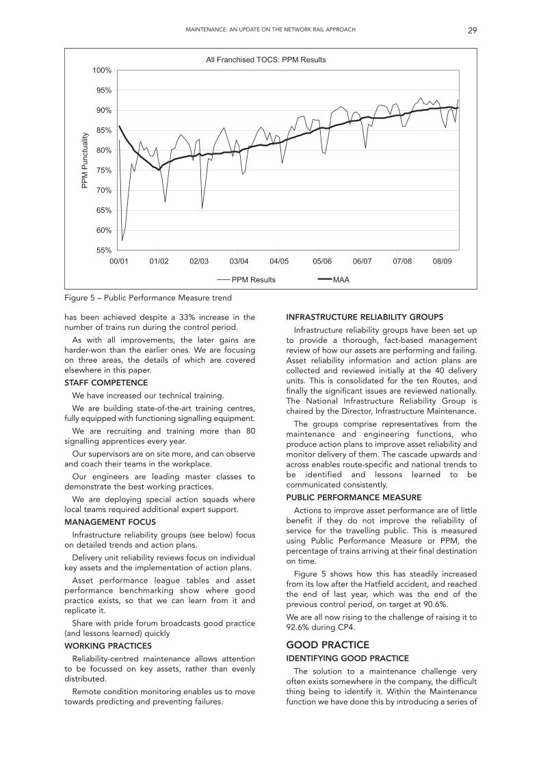
has been achieved despite a 33% increase in thenumber of trains run during the control period.
As with all improvements, the later gains areharder-won than the earlier ones. We are focusingon three areas, the details of which are coveredelsewhere in this paper.
STAFF COMPETENCE
We have increased our technical training.
We are building state-of-the-art training centres,fully equipped with functioning signalling equipment.
We are recruiting and training more than 80signalling apprentices every year.
Our supervisors are on site more, and can observeand coach their teams in the workplace.
Our engineers are leading master classes todemonstrate the best working practices.
We are deploying special action squads wherelocal teams required additional expert support.
MANAGEMENT FOCUS
Infrastructure reliability groups (see below) focuson detailed trends and action plans.
Delivery unit reliability reviews focus on individualkey assets and the implementation of action plans.
Asset performance league tables and assetperformance benchmarking show where goodpractice exists, so that we can learn from it andreplicate it.
Share with pride forum broadcasts good practice(and lessons learned) quickly
WORKING PRACTICES
Reliability-centred maintenance allows attentionto be focussed on key assets, rather than evenlydistributed.
Remote condition monitoring enables us to movetowards predicting and preventing failures.
29MAINTENANCE: AN UPDATE ON THE NETWORK RAIL APPROACH
INFRASTRUCTURE RELIABILITY GROUPS
Infrastructure reliability groups have been set upto provide a thorough, fact-based managementreview of how our assets are performing and failing.Asset reliability information and action plans arecollected and reviewed initially at the 40 deliveryunits. This is consolidated for the ten Routes, andfinally the significant issues are reviewed nationally.The National Infrastructure Reliability Group ischaired by the Director, Infrastructure Maintenance.
The groups comprise representatives from themaintenance and engineering functions, whoproduce action plans to improve asset reliability andmonitor delivery of them. The cascade upwards andacross enables route-specific and national trends tobe identified and lessons learned to becommunicated consistently.
PUBLIC PERFORMANCE MEASURE
Actions to improve asset performance are of littlebenefit if they do not improve the reliability ofservice for the travelling public. This is measuredusing Public Performance Measure or PPM, thepercentage of trains arriving at their final destinationon time.
Figure 5 shows how this has steadily increasedfrom its low after the Hatfield accident, and reachedthe end of last year, which was the end of theprevious control period, on target at 90.6%.
We are all now rising to the challenge of raising it to92.6% during CP4.
GOOD PRACTICEIDENTIFYING GOOD PRACTICE
The solution to a maintenance challenge veryoften exists somewhere in the company, the difficultthing being to identify it. Within the Maintenancefunction we have done this by introducing a series of
55%
60%
65%
70%
75%
80%
85%
90%
95%
100%
00/01 01/02 02/03 03/04 04/05 05/06 06/07 07/08 08/09
PP
M P
unct
ualit
y
PPM Results MAA
All Franchised TOCS: PPM Results
Figure 5 – Public Performance Measure trend
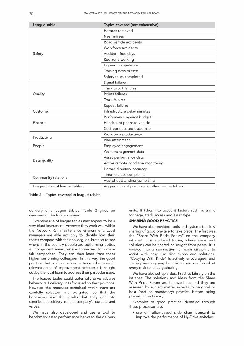
units. It takes into account factors such as traffictonnage, track access and asset type.
SHARING GOOD PRACTICE
We have also provided tools and systems to allowsharing of good practice to take place. The first wasthe “Share With Pride Forum” on the companyintranet. It is a closed forum, where ideas andsolutions can be shared or sought from peers. It isdivided into a sub-section for each discipline toassist with easy use discussions and solutions.“Copying With Pride” is actively encouraged, andsharing and copying behaviours are reinforced atevery maintenance gathering.
We have also set up a Best Practice Library on theintranet. The solutions and ideas from the ShareWith Pride Forum are followed up, and they areassessed by subject matter experts to be good orbest (and so mandatory) practice before beingplaced in the Library.
Examples of good practice identified throughthese processes are:
• use of Teflon-based slide chair lubricant toimprove the performance of Hy-Drive switches;
30 MAINTENANCE: AN UPDATE ON THE NETWORK RAIL APPROACH
delivery unit league tables. Table 2 gives anoverview of the topics covered.
Extensive use of league tables may appear to be avery blunt instrument. However they work well withinthe Network Rail maintenance environment. Localmanagers are able not only to identify how theirteams compare with their colleagues, but also to seewhere in the country people are performing better.All component measures are normalised to providefair comparison. They can then learn from thesehigher performing colleagues. In this way, the goodpractice that is implemented is targeted at specificrelevant areas of improvement because it is soughtout by the local team to address their particular issue.
The league tables could potentially drive adversebehaviours if delivery units focussed on their positions.However the measures contained within them arecarefully selected and weighted, so that thebehaviours and the results that they generatecontribute positively to the company’s outputs andvalues.
We have also developed and use a tool tobenchmark asset performance between the delivery
League table Topics covered (not exhaustive)
Hazards removed
Near misses
Road vehicle accidents
Workforce accidents
Safety Accident-free days
Red zone working
Expired competences
Training days missed
Safety tours completed
Signal failures
Track circuit failures
Quality Points failures
Track failures
Repeat failures
Customer Infrastructure delay minutes
Performance against budget
Finance Headcount per road vehicle
Cost per equated track mile
Workforce productivity
Plan attainment
People Employee engagement
Work management data
Asset performance data
Active remote condition monitoring
Hazard directory accuracy
Time to close complaints
Age of outstanding complaints
League table of league tables! Aggregation of positions in other league tables
Table 2 – Topics covered in league tables
Productivity
Community relations
Data quality
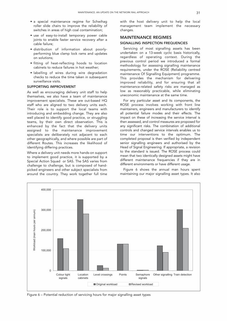
• a special maintenance regime for Schwihagroller slide chairs to improve the reliability ofswitches in areas of high coal contamination;
• use of easy-to-install temporary power cablejoints to enable faster service recovery after acable failure;
• distribution of information about poorly-performing blue clamp lock rams and updateson solutions;
• fitting of heat-reflecting hoods to locationcabinets to reduce failures in hot weather;
• labelling of wires during wire degradationchecks to reduce the time taken in subsequentsurveillance visits.
SUPPORTING IMPROVEMENT
As well as encouraging delivery unit staff to helpthemselves, we also have a team of maintenanceimprovement specialists. These are out-based HQstaff who are aligned to two delivery units each.Their role is to support the local teams withintroducing and embedding change. They are alsowell placed to identify good practice, or strugglingteams, by their own direct observation. This isenhanced by the fact that the delivery unitsassigned to the maintenance improvementspecialists are deliberately not adjacent to eachother geographically, and where possible are part ofdifferent Routes. This increases the likelihood ofidentifying differing practices.
Where a delivery unit needs more hands-on supportto implement good practice, it is supported by aSpecial Action Squad or SAS. The SAS varies fromchallenge to challenge, but is composed of hand-picked engineers and other subject specialists fromaround the country. They work together full time
with the host delivery unit to help the localmanagement team implement the necessarychanges.
MAINTENANCE REGIMESSIGNALLING INSPECTION FREQUENCIES
Servicing of most signalling assets has beenundertaken on a 13-week cyclic basis historically,regardless of operating context. During theprevious control period we introduced a formalmethodology for assessing signalling maintenancerequirements, under the ROSE (Reliability centredmaintenance Of Signalling Equipment) programme.This provides the mechanism for deliveringimproved reliability, and for ensuring that allmaintenance-related safety risks are managed aslow as reasonably practicable, while eliminatinguneconomic maintenance at the same time.
For any particular asset and its components, theROSE process involves working with front linemaintainers, engineers and manufacturers to identifyall potential failure modes and their effects. Theimpact on these of increasing the service interval isthen assessed, and control measures are proposed forany significant risks. The combination of additionalcontrols and changed service intervals enables us totime our interventions to the optimum. Thecompleted proposal is then verified by independentsenior signalling engineers and authorised by theHead of Signal Engineering. If appropriate, a revisionto the standard is issued. The ROSE process couldmean that two identically designed assets might havedifferent maintenance frequencies if they are indifferent environments or have different usage.
Figure 6 shows the annual man hours spentmaintaining our major signalling asset types. It also
31MAINTENANCE: AN UPDATE ON THE NETWORK RAIL APPROACH
0
100,000
200,000
300,000
400,000
Colour lightsignals
Locationcabinets
Level crossings Points Semaphoresignals
Other signalling Train detection
Wor
kloa
d (m
an h
ours
per
ann
um)
Original workload Revised workload
Figure 6 – Potential reduction of servicing hours for major signalling asset types
TRACK INSPECTION FREQUENCIES
The other asset type with significant potential forapplying reliability centred maintenance techniquesis the track. At present, track inspections are carriedout to prescribed frequencies mandated bycompany standards. These usually require weeklyinspections on most routes. The frequency of ourinspections compares unfavourably with the rest ofEurope (see Table 5). Despite introducing one of themost advanced track inspection train fleets in theworld, we have not reduced the frequency ofpedestrian inspection correspondingly.
Appendix A of the applicable standard for routinetrack patrolling contains a risk-based method for
32 MAINTENANCE: AN UPDATE ON THE NETWORK RAIL APPROACH
shows the potential for efficiencies as ROSE isimplemented. Note that this excludes any changesto points servicing frequencies. We have alreadycreated opportunities associated with standardisingfacing point lock testing intervals, are now workingwith the newly created Head of Switch and CrossingEngineering to identify wider potential benefits forthese asset types.
Selecting asset types which are currently over-maintained has allowed servicing of many assets tobe reduced from four times per year, to two, or evenone. Table 3 shows the progress to date.
Although the ROSE programme is not new, thebenefits of the work done to date have yet to befully realised. This is because ROSE is not just ananalytical process. It requires significant businesschanges to allow it to be properly implemented. Inorder to benefit from the technical analysis,servicing work must be regrouped andreprogrammed so that as far as possible the needfor a visit to site is completely eliminated. This isbecause the largest time element associated withservicing an asset, or a group of assets at one site, isthe travelling and set-up time, rather than theduration of the servicing activity itself.
Some small workload or small population assettypes are also included in the programme (such asChiltern ATP and the “Indusi” train stop system usedin the North East). These are included specifically toprovide local managers with greater flexibility torealise benefits, by providing a greater number ofpotential combinations of asset types with revisedservicing intervals. Table 4 shows the next assets tobe included in the ROSE programme.
The benefits of ROSE are not just related to staffsafety and efficiency. The freed up resource can beredeployed to carry out enhanced maintenance ofcritical asset types, or to carry out additional worksuch as special inspections, pre-emptive repairs, orminor upgrades.
The ROSE process can be applied to other assettypes. We are currently reviewing the potentialbenefits of changing servicing frequencies fortelecoms and plant assets.
Table 3 – Progress to date with ROSE
Analysis Population Change Status
ATP (Chiltern) 258 4 visits a year to 1 Complete
Signs unknown 4 visits a year to 1 Complete
DC track circuits 23,800 4 visits a year to 2 Phase 1 complete
Facing point lock tests 21,000 Variable Complete for 75% of points
TPWS 15,000 4 visits a year to 1 Complete
AWS 24,000 4 visits a year to 1 Complete
Colour light signals 23,000 4 visits a year to 2 Complete
LED signals 1,300 4 visits a year to 1 Complete
TI21 track circuits 7,700 4 visits a year to 2 Complete
HVI track circuits 3,280 4 visits a year to 2 Complete
2 or 4 visits a year to 1,AzLM axle counters 3,200 based on the use of Complete
diagnostics
Analysis Population
Aster Type U track circuits 3,000
Location cases 70,000
AC track circuits 5,700
Clamp-lock points 7,700
DC track circuit (low voltage) 14,000
Electronic interlockings 100
FS2000 track circuits 350
Ground frames 1000
Type HPSS point machines 460
Type HW point machines 7,900
Level crossings 1,600
Mechanical interlockings 800
Mechanical points 3,000
Mechanical signals 2,000
Reed track circuits 2,000
Siemens axle counters 300
Style 63 point machines 1,600
Type T72/VCC point machines 69
Train describers 400
Train operated points 100
Table 4 – Next phases of ROSE
33MAINTENANCE: AN UPDATE ON THE NETWORK RAIL APPROACH
increasing the patrolling intervals for continuouslywelded rail, subject to various documentedconsiderations. Exploiting the potential of reliabilitycentred maintenance for track requires the samelevel of business change as for signalling. Onceagain the benefit is realised by reorganisingpatrolling programmes, and by optimising theamended frequencies for plain line track inspectionwith the usually more frequent needs of switch andcrossing inspection.
REMOTE CONDITION MONITORING
Network Rail is investing heavily in the installationof fixed remote condition monitoring (RCM) of ourassets. The benefits of this are two-fold. Firstly thereare significant train performance benefits. SecondlyRCM will provide accurate supporting data toenable us to continue our migration towards a fullyrisk-based maintenance regime.
We have had pockets of RCM fitted for manyyears, mainly on points, but also on power supplies,interlockings, level crossings, bridges and rails. Siteswere selected in a relatively ad hoc manner, usingequipment from a variety of suppliers. This has
≤ 50 1 4 26 6 13 2 8
≤ 75 1 4 26 6 13 2 8
≤ 100 1 4 16 6 13 2 8
≤ 140 1 4 12 * * 2 4
* Information not supplied
Table 5 – Comparison of patrolling intervals
Bri
tain
Po
rtug
al
Ger
man
y
Bel
giu
m
Ho
lland
Swit
zerl
and
Fran
ce
Line
speed,
mph
Minimum plain line patrolling inspection interval, weeks
resulted in a range of different functionalities andinconsistent business processes. Despite this,performance benefits have been substantial. As aconservative estimate a 30% reduction of bothincidents and delay minutes is achieved routinelywithin a year of installing RCM on points, providedthe technology is supported by robust managementprocesses.
Network Rail’s strategy has two elements: tostandardise the remote condition monitoringtechnology and processes in use on our assets; andto link the outputs from different locations so as toprovide an information-rich environment that willenable us to predict and prevent failures, througheither targeted renewal or customised maintenanceregimes.
With standardised logger and data outputspecifications, the outputs from the remotecondition monitoring can be managed consistently.In future, for new installations this will be done via arecently commissioned Network Rail central system(see Figure 7). Sensors attached to an asset providedata to an on-site logger; for example, for a set of
Figure 7 – Schematic of “intelligent infrastructure” remote condition monitoring process
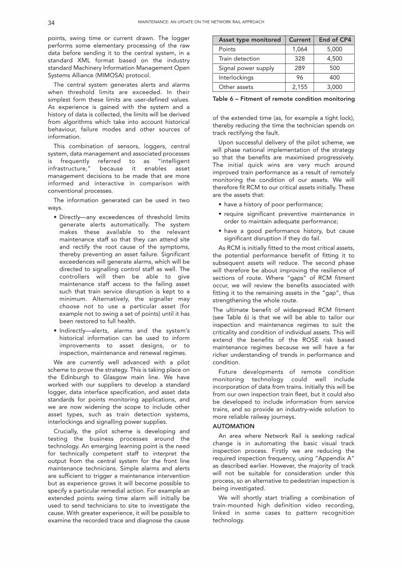
points, swing time or current drawn. The loggerperforms some elementary processing of the rawdata before sending it to the central system, in astandard XML format based on the industrystandard Machinery Information Management OpenSystems Alliance (MIMOSA) protocol.
The central system generates alerts and alarmswhen threshold limits are exceeded. In theirsimplest form these limits are user-defined values.As experience is gained with the system and ahistory of data is collected, the limits will be derivedfrom algorithms which take into account historicalbehaviour, failure modes and other sources ofinformation.
This combination of sensors, loggers, centralsystem, data management and associated processesis frequently referred to as “intelligentinfrastructure,” because it enables assetmanagement decisions to be made that are moreinformed and interactive in comparison withconventional processes.
The information generated can be used in twoways.
• Directly—any exceedences of threshold limitsgenerate alerts automatically. The systemmakes these available to the relevantmaintenance staff so that they can attend siteand rectify the root cause of the symptoms,thereby preventing an asset failure. Significantexceedences will generate alarms, which will bedirected to signalling control staff as well. Thecontrollers will then be able to givemaintenance staff access to the failing assetsuch that train service disruption is kept to aminimum. Alternatively, the signaller maychoose not to use a particular asset (forexample not to swing a set of points) until it hasbeen restored to full health.
• Indirectly—alerts, alarms and the system’shistorical information can be used to informimprovements to asset designs, or toinspection, maintenance and renewal regimes.
We are currently well advanced with a pilotscheme to prove the strategy. This is taking place onthe Edinburgh to Glasgow main line. We haveworked with our suppliers to develop a standardlogger, data interface specification, and asset datastandards for points monitoring applications, andwe are now widening the scope to include otherasset types, such as train detection systems,interlockings and signalling power supplies.
Crucially, the pilot scheme is developing andtesting the business processes around thetechnology. An emerging learning point is the needfor technically competent staff to interpret theoutput from the central system for the front linemaintenance technicians. Simple alarms and alertsare sufficient to trigger a maintenance interventionbut as experience grows it will become possible tospecify a particular remedial action. For example anextended points swing time alarm will initially beused to send technicians to site to investigate thecause. With greater experience, it will be possible toexamine the recorded trace and diagnose the cause
34 MAINTENANCE: AN UPDATE ON THE NETWORK RAIL APPROACH
of the extended time (as, for example a tight lock),thereby reducing the time the technician spends ontrack rectifying the fault.
Upon successful delivery of the pilot scheme, wewill phase national implementation of the strategyso that the benefits are maximised progressively.The initial quick wins are very much aroundimproved train performance as a result of remotelymonitoring the condition of our assets. We willtherefore fit RCM to our critical assets initially. Theseare the assets that:
• have a history of poor performance;
• require significant preventive maintenance inorder to maintain adequate performance;
• have a good performance history, but causesignificant disruption if they do fail.
As RCM is initially fitted to the most critical assets,the potential performance benefit of fitting it tosubsequent assets will reduce. The second phasewill therefore be about improving the resilience ofsections of route. Where “gaps” of RCM fitmentoccur, we will review the benefits associated withfitting it to the remaining assets in the “gap”, thusstrengthening the whole route.
The ultimate benefit of widespread RCM fitment(see Table 6) is that we will be able to tailor ourinspection and maintenance regimes to suit thecriticality and condition of individual assets. This willextend the benefits of the ROSE risk basedmaintenance regimes because we will have a farricher understanding of trends in performance andcondition.
Future developments of remote conditionmonitoring technology could well includeincorporation of data from trains. Initially this will befrom our own inspection train fleet, but it could alsobe developed to include information from servicetrains, and so provide an industry-wide solution tomore reliable railway journeys.
AUTOMATION
An area where Network Rail is seeking radicalchange is in automating the basic visual trackinspection process. Firstly we are reducing therequired inspection frequency, using “Appendix A”as described earlier. However, the majority of trackwill not be suitable for consideration under thisprocess, so an alternative to pedestrian inspection isbeing investigated.
We will shortly start trialling a combination oftrain-mounted high definition video recording,linked in some cases to pattern recognitiontechnology.
Asset type monitored Current End of CP4
Points 1,064 5,000
Train detection 328 4,500
Signal power supply 289 500
Interlockings 96 400
Other assets 2,155 3,000
Table 6 – Fitment of remote condition monitoring
SWITCH AND CROSSING VIDEO INSPECTION
Removing the need to inspect switches andcrossings (S&C) on foot has significant benefits. Thevast majority of S&C must be inspected in daylightbecause of the complex components. Stationthroats frequently have many sets of S&C in a smallarea, and the only way to inspect them on footsafely is to take possession of the line. This in turnrestricts the usage of the station by passengertrains. Introducing a process that does not requiretrack possessions frees up the railway to run trains,a major industry aspiration under the “Seven-DayRailway” programme, and removes staff from a highrisk environment.
The trial is replicating technology and processescurrently in operation in Holland. Video equipmentis mounted on a dedicated Multi Purpose Vehicle. Itwill run in traffic and capture images of S&C. Theseimages will then be processed and transferred to alocal inspection suite where track inspectors canexamine them in comfort and safety.
PLAIN LINE VIDEO INSPECTION
Downward-facing video equipment is fitted onthe New Measurement Train to capture images ofthe track to a similar standard as the S&C videoreferred to above. The vast volume of track coveredmakes it unfeasible to view all of the data andimages manually to identify defects. Thereforesoftware is needed to provide defect reports for thetrack inspectors. This software automaticallyidentifies defects, and produces exception reportsfrom the captured data. These can be linkedautomatically to images of any defects identified.The exception report identifies significant variationsbetween recent surveys so that the whole run doesnot have to be viewed. Track inspectors canexamine the exception report and associated videoimages remotely in the inspection suite.
THE SEVEN-DAY RAILWAYWhere there is an industry business case, NetworkRail has committed to work with train operators torun new train services on routes and at times thataddress customer demand. This means principallyrunning a consistent, timetabled train service everyday of the week.
The initiatives to support this commitment are amix of infrastructure improvements, use of newproducts and changed methods of working. Thefollowing are examples of maintenancecontributions to the Seven-Day Railway.
IMPROVED ACCESS POINTS
New and better access points will reduce both thetravelling time and the access time to reach criticalassets.
JUNCTION LIGHTING
Installation of fixed lineside lighting of sufficientintensity, evenness and extent will enable patrolling,
inspection and maintenance to be undertaken in thehours of darkness.
RCM
Remote monitoring of assets in service will assesstheir performance and determine likely failuremodes. Predicting failure modes will allow moreefficient scheduling of planned maintenance forrepair and replacement, allowing maintenanceactivity to move from “fix and find” to “predict andprevent.”
LOOKOUT OPERATED WARNING SYSTEM
The Lookout Operated Warning System or LOWSallows mid-week daytime opportunities to accessthe track, enabling some activities to be spreadaway from valuable track possessions.
MOTORISED INSPECTION TROLLEYS
Lightweight motorised trolleys fitted with lightingenable patrolling, inspection and maintenance to beundertaken in the hours of darkness.
VIDEO INSPECTION OF SWITCHES ANDCROSSINGS
This will reduce the amount of track accessrequired at complex switch and crossing layouts.
SWITCH AND CROSSING GANTRIES
Specialised lifting gantries will enablereplacement of large switch and crossingcomponents in fewer, shorter possessions. They willalso reduce the risk of component damage duringinstallation.
RAIL REPAIR TECHNIQUES
Faster rail head and crossing repair techniquesmean that rails can be repaired in fewer, shorterpossessions.
ROSE
Increased servicing intervals reduce the need toaccess the track to maintain signalling equipment.
CONCLUSIONThese are exciting times to be maintaining
Britain’s railways. The challenges set for the comingfive years mean that we need to make significantchanges to the way we work. To do this, we must beable to identify good practices from within NetworkRail or elsewhere, and implement them consistentlyand swiftly. Our standard organisation provides theframework for this, but effective sustainable changecan only be delivered by a competent, motivatedwork force. We must examine critically every activitythat we carry out, and decide if we can eliminate it,simplify it, or rationalise it, or only then whether wecan automate it.
The challenges are not easy, but we welcome ouropportunity to make a lasting improvement. And wemust do this without losing sight of our mostimportant challenge – to keep the travelling publicand our staff safe whilst delivering a reliable andefficient network.
35MAINTENANCE: AN UPDATE ON THE NETWORK RAIL APPROACH
36 MAINTENANCE: AN UPDATE ON THE NETWORK RAIL APPROACH
Summary of discussion of paper by S. Featherstoneentitled “Maintenance, An Update on the NetworkRail Approach” given on 14th October 2009.
The discussion was opened by J. Poré (Alstom)who thought that what had been achieved in the lastcouple of years was impressive and he wonderedwhere Network Rail went next. He noted thereference to the use of on-train and track-sidemonitoring to initiate maintenance intervention butstill questioned the high number of broken railscompared with (say) Japan. Referring to the deliveryunits and daily graphs produced, he asked if this wasused to influence staff bonuses. Finally he observedthat the presentation made little reference to theultimate customers, the passengers and freightcarriers, and he questioned what Network Rail wasdoing in this area.
S. Featherstone explained that benchmarking hadshown favourable results in some areas but there isstill much to learn from the Dutch and Swiss, such asvideo-patrolling. He advised that there is aperformance assessment process within thecompany and the league tables influence howpeople are judged. He confirmed that there areregular meetings with customers whose key concernis infrastructure reliability, hence the daily leaguetables, however, as the reliability has improved thereare now other concerns being raised such asvegetation and graffiti issues.
F. How (RIA) commented that it was a remarkablestory which will be a challenge to sustain. As arepresentative of the supply industry, he noted thatthere was no feedback from Network Rail on howmanufacturers’ equipment actually performs in thefield, unless there was some major issue, and heasked if Network Rail planned to introduce asystematic process to achieve this; he believed thatthis would result in real gains for both Network Railand the supply industry.
S. Featherstone agreed totally but explained thatinitially they had concentrated on some big internalreliability fixes but now that these had been tackledthey were now looking to improve supplier reliability.As an example, with the HPSS problems that havebeen experienced, Network Rail have worked backthrough the supply chain to ensure that allcomponents used are as reliable as possible.
R. Skillet (LU) was interested in the speed withwhich the 2A organisation was developed andimplemented and was interested in knowing whatfactors had influenced the process.
S. Featherstone advised that the process hadtaken nine months from initial discussions toimplementation; for stages 2B/C, preliminarydiscussions began in August 2009 with a proposedcommencement date of April 2010 through to March2011 for full implementation to occur.
P. Woodbridge (Invensys) asked if the maintenanceorganisation could influence project specificationsnoting that the figures available show that the morerecently installed equipment tends to be less reliablethan the more established items.
S. Featherstone believed that some problemswere explained by the new equipment mirroring thetypical bath-tub curve and thought that theestablished equipment had probably alsoexperienced similar problems when they had initiallybeen commissioned. He also explained that NetworkRail had been to see how the aviation industry hadovercome these sort of problems and their approachto reliability with any lessons learnt taken on-board.With the on-going maintenance costs as a result ofcapital investment during CP2/3, there had been ageneral philosophy of “least first-costs” with noconsideration for efficient maintenance. Thatsituation is now changing, however, withmaintenance representatives embedded in themajor project teams to ensure continuedmaintainability both during and after the projecttogether with a more definite “whole-life” costapproach.
F. Heijnen (IRSE President) returned to thequestion of project specifications and asked if themaintenance organisation was able to input intoresilience, reliability and diversity requirements toreduce costs and hence support the 24-hour railwayconcept.
S. Featherstone agreed that it was particularlyimportant and explained that the aviation industryhad changed their philosophy to “power-by-the-hour” which placed the onus on the supply industryto either manufacture reliable products or losemoney. The railway model has not yet achieved thisbut Network Rail is focussed on getting the requiredreliability.
C. Porter (IRSE) observed that the holy grail ofinfrastructure maintenance had always been to tryand get the maintenance and faulting staff to multi-skill and wondered if this was being investigated as ameans of achieving efficiencies.
S. Featherstone thought that multi-skilling wasmisunderstood and that it probably wouldn’t happenwith the different core skills required for eachdiscipline although there may be some areas wheresimilar technologies, such as point maintenance,might allow this “overlapping” of skills to happen.
P. Bartlett (Booz and Co.) asked, other than beenable to predict equipment failures, what was thebusiness case for the installation of conditionmonitoring, and on which assets, and also if newprojects included its provision in their specifications.
S. Featherstone clarified that the business casewas primarily based on customer service and delayminutes (Schedule 8 payments) in the short term,which incentivises Network Rail to provide a reliableinfrastructure. Determination of asset fitment isbased on various factors but, as an example, theWest Coast has fitted “RCM light” where the 80/20rule has been applied (80% of the benefits for 20%of the cost) whereas somewhere like Liverpool Streetwould be fully fitted; this concept could also makesome of the community railways more viable.Acquisition of data from these monitoring systems
Discussion
was also used to assist in the implementation ofreliability centred maintenance leading to a costsaving. He finally explained that for all new projects,and following a recent standard change, the fittingof condition monitoring now has to be considered inall cases.
B Dutta-Chowdhury (Bombardier) questionedwhat was being planned to improve maintenance onthe secondary lines and how were the inter-disciplinary issues of changes to the maintenanceregime being approached.
S. Featherstone explained that the league tablesdo not differentiate between the type of linesmaintained by the Delivery Units but specialist skillsare obviously still required for certain areas of theinfrastructure and that was one objective of theMaster Classes. The cross-discipline approach hasbeen ensured by including the Engineering Team insolving problems.
G. Parris (LU) referred to the importance ofcompetence and technical training provided butwondered if the safety engineering management
training had been included when taking into accountthe rapid promotion of many younger members ofstaff into Supervisory roles.
S. Featherstone stated that one of the successcriteria would be the skill base of the Supervisorystaff and explained that there is a programme oftraining for these people to equip them with thenecessary skills that can be applied to the technical,safety and business management as well as thedecision-making process; this will be an on-goingprocess.
F. Heijnen (IRSE President) reiterated that trainingand competence was an important subject thatcould not be ignored; finally he thanked the Speakerfor his paper, which had demonstrated how theperformance of Network Rail had improved since theRailtrack days, and also for his participation in thequestion and answer session that had followed.
(Produced by Peter Grant)
37MAINTENANCE: AN UPDATE ON THE NETWORK RAIL APPROACH
INTRODUCTIONThis paper has two themes. The first concerns the
need to ensure the continuity of signal engineersable to see the big picture. The second looks at theway that signalling is provided and, in particular, therole of assurance in the signalling process.
It endeavours to show that there are linkagesbetween the two and that the industry has to faceup to the changes that have taken place. Finally itproposes a way forward to enable the signallingindustry to remain economic and efficient.
It relies heavily on the author’s experience and sois written from the point of view of Metro signallingin the United Kingdom. It should not be seen asrelating to any particular organisation. However itattempts to bring in the experience of nationalrailways and of other countries.
SCENE SETTINGIs perception reality? The following are views
currently held by many outside the signallingindustry and often expressed by those within it (seeRef. 1).
38
Technical Meeting of the Institutionheld at
1 Birdcage Walk, London
Wednesday 11th November 2009The President, Mr F Heijnen, in the chair.
147 members and visitors were in attendance. There was an apology for absence from David McKeown. It was proposed by Mr K W Burrage seconded by Mr R W Penny and carried that the minutes of
the technical meeting held on 14 October 2009 be taken as read and they were signed by Mr Heijnen as a correct record. The Chairman then invited any new members present for the first time since their election to come forward to be introduced to the meeting. Mr Alastair
Hayden (London Underground) came forward to be introduced to warm applause. The Chairman then introduced Eddie Goddard (Past President and Head of Engineering, Line Upgrades, London Underground Ltd) and asked him to
present his paper “Signalling – Have we lost the plot?”In opening his presentation, Mr Goddard emphasised he was speaking for himself as a Past President of the Institution, rather than his role with LUL. He
outlined the early development stage of his own career, being introduced to work in the drawing office, and the initial introduction of computers into controlsystems, and went on to describe the working arrangements which used to exist between both railways and suppliers and the use of cost plus contracts whichfacilitated the achievement of projects. He went on to talk about the evolution of “safety” as a bolt-on product rather than the incorporation of processesthroughout the design and implementation lifecycle from the basics of defining the requirements before developing the solution, the design checkingprocesses and final testing and commissioning, comparing the traditional fail-safe and newer processor based signalling systems. Finally he drew attention tothe size and weight of documentation for standards and safety cases, and he felt that was not the best way forward. He finished by stressing the importanceof audit trails and the need for a risk based approached to assurance.
Following the presentation, the discussion was opened by Wim Coenraad (Movares - Past President). Malcolm Savage (consultant), David Jeffrey (Invensys),David Waboso (LUL), Malcolm Dobell (LUL), David Mills (retired), Roger Short (Atkins), Andrew Bourne (Tube Lines), Robert Blackadder (Siemens), RichardLockett (ERA), Chris Thompson (HonF), Frans Heijnen (President) and Cy Porter (Past President) all took part in the discussion.
The Chairman then thanked the speaker and proposed a vote of thanks to him for supporting his theme for the year, which was very much about futuretraining for signal control and communications engineers. He then presented him with a commemorative plaque customarily awarded to the author of a Londonpaper.
Mr Heijnen thanked members and visitors for their attendance and their contribution, and then closed the meeting at 2000 by reminding those presentabout the technical visit to Scotland on 20/21 November, and a seminar on Training and careers in S&T Engineering on 24 November in London. He announcedthat the next meeting in London would be a technical meeting held on the 9 December 2009 when Mr Ian Mitchell would present a paper entitled “SustainableRailway: Use of Advisory Systems for Energy Savings”.
1 The author is a past President of the IRSE.
Signalling: Have We Lost the Plot?Eddie Goddard1
They don’t make them like they used to.
“When the current breed of signal engineersretire there will be no one left that understandsthe whole picture.All that we have now are specialists.”
The weight of evidence.
“The amount of documentation for a projectgenerated to satisfy the assurer(s) outweighs thatused to develop the project itself. The criticalpath now lies through the assurance chain. As aresult project cost and implementation time arebecoming untenable.”
Why do these things matter? If they are true, thenthe cost of introducing new systems will becomeunbearable, signalling unaffordable and delaysunacceptable. If we do not do something we will beleft behind. Railways themselves will becomeuneconomic and will fall into decline. The benefitsthat they can bring will be lost, and we will all be outof a job. Even if they are not true the perception isstill there, and unless we are able to counter it thesignalling industry will be marginalised andinvestments made elsewhere (see Ref. 2). What ismore likely is that new companies will be formedwhich are more willing to adopt new ways and ableto undercut the traditional suppliers throughadopting a radical approach.
SIGNALLING: HAVE WE LOST THE PLOT? 39
THEY DON’T MAKE THEM LIKE THEYUSED TOCAREER DEVELOPMENT
To develop these themes the paper will considerthe career of a typical signal engineer of an earliergeneration—as experienced by the author at thetime.
Training
A total apprenticeship of six years, starting as aDip Tech Trainee.
Academic English, Maths and Physics at schoolSponsored for a Degree in Electricaland TelecommunicationsEngineering, and a Master’s Degreein Systems Engineering.
Practical Time spent in workshops, with theMaintainer on call and with aninstallation gang. Knowledge gainedof practicalities, as well as thecultures of the different disciplines.
Signalling Power Signal Linesman course and theory Drawing Office course.
Management British Rail junior management theory course.
Railways Time spent with Divisional Inspectoron stations and with drivers, lookinginto incidents and observing his staffmanagement. Absorbing front-lineoperator’s culture.
Time spent in control rooms andgenerally out and about on therailway.
Project Produced a railway simulator for theVictoria Line through extensive workwith rolling stock engineers tounderstand train characteristics.
Testing New communications system on liverails in an automatic train area. Onthe track, no lookouts, no briefing,no personnel protection equipment.
Doing
Design
Producing “red inks” by copying the work of theEngineering Assistant (just two years older thanmyself!), then preparing circuits and having themchecked. Being given feedback on the design andhence learning the best way. Seeing the approverwork with the Engineering Assistant and hisexperience being fed back. Later still, seeing thetwo principal designers in active debate about themore esoteric aspects of the design.
Installation
Held the meter for the Principal Installationassistant (Tester in charge). Observed the finalcommissioning process where the tester, withoutreference to the circuits but using the scale plan andworking from first principles ensured that the siteperformed as it should by using track droppingboards and lots of staff. Saw design anomaliespicked up and circuit changes made through thedesigner sitting alongside the tester. Later, put in
charge of testing a signal! Realising the homeworkthat went into the testing process with study ofcircuits, and discussion of the designs before testingtook place.
Development
Put in charge of making a new communicationssystem work. Working directly with supplier’s teamand devising modifications. Jointly installing andtesting them.
Railway
Working with Rolling Stock Engineers, spendingconsiderable time with Line Controllers and TrainRegulators and riding in train cabs.
Management
Working in a multidisciplinary team with a senioroperator, timetable compiler and data processingexpert on specification of a computer-based railwaycontrol system (see Ref. 3).
Consultancy
Providing independent assurance to signallingcontractors for novel signalling systems throughLondon Transport’s external consultancy arm. As aresult exposed to other countries’ signallingcultures, and to commercial pressures.
Managing
Development
Leading the team introducing computer controlsystems for the Underground. Providing theengineering support to the cross directorate team(engineering, operations, revenue collection,supplier) developing the Underground’s automaticfare collection and selling systems (which becameOyster) with the supplier.
Maintenance
Responsible for the signalling maintenancedivision.
Client
Managing the Signalling client organisation.
Systems
Managing the Rolling Stock and Signalling clientorganisations, and forming the Systems Engineeringteam.
International committees
Working on standards-setting committees for RIA,ORE, and the IRSE technical committee. Gainingwider appreciation of different signalling andoperating companies, different cultures, anddifferent commercial arrangements.
Professional career
Supported throughout career on IRSE activities,attending lectures and conventions as a student,granted time to attend council meetings, through tosupport during presidential year.
Assuring
Chief Engineer
Managing the team that produces standards andenforces compliance for all engineering disciplines.
SIGNALLING: HAVE WE LOST THE PLOT?
Chairman of safety review panels
Approving introduction of new technology andsystems.
Career Development
Underlying all the above was the certainknowledge that a full career could be followedthrough one employer; that the training managerhad mapped out the early stages and providedmentoring through those difficult times; and thatthe senior managers had devised career progressionplans, and that one’s promotion was often subject tothose plans. Sideways and even downward moveswere encouraged, with the promise that “rescuewould be at hand” should the move prove to be toodisastrous.
THE SIGNALLING WORLD
Railways
Railways were largely self-contained. They dideverything themselves. (London Underground evenhad its own power generating stations).
They were staffed to a great extent by formersoldiers and mariners, and organised as operations,engineering disciplines, and support. Eachengineering discipline was led by a Chief Engineeraccountable for development, design, installationand maintenance. The Chief made decisions, rightor wrong, and was accountable for them. He knewall aspects and was capable of, and indeed far toofrequently did, issue detailed designs himself(Robert Dell when Chief Signal Engineer would issuehis circuits in green ink so that everyone knew not toquestion them!)
Suppliers
Suppliers built what they were asked to build.Research and development were carried out jointlyunder profit sharing agreements, with engineeringdecisions being made first and commercialconsequences agreed later. Engineers workedtogether as a team, each having his own role.When things went wrong, they fixed them. Theresult was often gold-plated signalling—thankgoodness, because most of it is still in commission,and working well beyond its expected life of fortyyears.
SAFETY
Safety was embodied in the fail-safe concept.Every effort was made to understand the failuremodes of components and eliminate the causes ofwrong side failures (see Ref. 4). As a result interfaceproblems were greatly simplified, in that eachcomponent in the chain took on trust that thepreceding ones would fail safe and so did not haveto consider any complex interactions.
Reliability was seen as subservient to safety.
On London Underground a clear distinction wasmade between safety and non-safety circuits, sothat the safety circuitry was kept as simple aspossible (see Ref. 5).
Personnel safety was largely based on drumminginto people just how dangerous the railway was, andthen expecting them to look after themselves. As aresult working on the railway was seen as the second
most dangerous occupation, after the miningindustry.
Assurance
Although the word “assurance” would not havebeen recognized in this context then, the pursuit ofever-increasing levels of safety was ingrained in allsignal engineers, and closely linked to thehierarchical chain. Engineering managers weretechnically competent in the main, and had risenthrough the ranks. They were fully empowered tomanage, they made decisions and they managedthe budgets. They were accountable for delivery tocost and to time, and for the quality of the endresult.
Designs were “Checked” and “Approved” by thedesign engineer’s manager as part of the normalproduction process. They would sign off the designsonly when satisfied that they were correct. Schemeswere approved by the Design Engineer.Independent checking was carried out betweendrawing offices and through discussion with theinstallers and testers.
Components were tested in the supplier’s factoryand signed off by competent inspectors, 100%checking being the norm. Critical components wereretested by the railway.
Installers’ work was checked by wire counts andtesting initially, to prove that the circuits worked asdesigned (verification). Then it was checked by asenior tester to ensure that it met all the signallingprinciples and enabled the operator to run theintended service safely (validation). At each stage asimple signature sufficed.
Close attention was paid to every failure and theroot cause was sought, be it equipment, proceduralor human error.
Her Majesty’s Railway Inspectorate – theRegulator
HMRI staff were traditionally ex-military. They sawtheir role as that of an enforcer, but they always hadthe clear motivation to improve the railway and itssafety and to protect the workforce. They looked toensure that there was adequate paperwork, butspent most of their time talking to the people—operators, engineers and managers alike. Theysought evidence principally through testing thecalibre of the people they talked to.
They gave approvals following a stagedinterrogation. “Cooksey’s Court” was alwayssomething that had to be prepared for, and it nearlyalways surprised with the perception of thequestions asked (see Ref.6).
They were able to turn a blind eye on occasionsbut let the managers know they had done so.
They conducted enquiries with the aim of finding outwhy the accident had happened and preventing ithappening again.
FROM THEN TO NOWEDUCATION
Engineering as a profession fell out of fashion, anduniversities have struggled to recruit good schoolleavers. In a survey in 1997 only 60% of
40
schoolchildren over 16 had even heard ofengineering as a career, less than 3% wereinterested in railways (see Ref. 7). Sponsorship forengineering courses and apprenticeships becamescarce. The few graduates that emerged wereattracted to lucrative careers in finance. As a resultthe flow of young engineers all but dried up. Poorpublicity about railways made it hard to recruit fromeven this depleted pool of talent.
RAILWAYS
The old monoliths have been broken up. Onnational railways, operation has been franchised totrain operating companies, rolling stock is providedby rolling stock companies, signalling andpermanent way by infrastructure companies.
Even in Metros the maintenance has often beenfranchised out, and new signalling and rolling stockprovided by outside suppliers.
SUPPLIERS
Suppliers have formed into large internationalconsortia. They have been required to take on manyof the roles previously performed by the railwaycompanies.
At the same time they have continued toconcentrate on manufacture, with applicationdesign, installation, commissioning, maintenanceand assurance often being franchised out to smaller,niche companies.
SAFETY
Safety has become an industry in itself.Companies have been formed or consultancies havetaken on the role of assurer. In part this is throughthe requirements for independent safety assuranceto satisfy the requirements of EN61508 and fornotified bodies to satisfy the EuropeanCommission’s need to demonstrate faircompetition.
It is also however a reflection of how difficult it isto meet the expectations of the safety industryitself—that is, to prepare safety cases, proofs ofsafety, safety plans etc. in order to demonstrate thatthe requirements arising from the criterion, “As LowAs Reasonably Practicable” have been met.
Software and communications-based systems aremore difficult to understand than the old signallingcircuits. It is harder to see the whole picture Theintroduction of project managers separate fromengineers results in a tendency for the engineers toconcentrate on quality and leave the need to meettimescales and budgets to the project manager, andvice versa. As a result decisions are often made inpractice by the person with the most power ratherthan the one with the best knowledge.
REGULATION
Perhaps the biggest change was the need forregulators to reflect the change that had taken placein public perception. It is no longer the case that“accidents happen.” It is necessary to show thatsomeone is to blame. As a result court cases followany accident, and evidence is required todemonstrate that correct procedures have been
followed. Engineering judgement alone is no longeracceptable as an explanation for decisions. Evenregulators find their decisions questioned andaction threatened against them.
As a result the whole industry has become highlydefensive. It is no longer wise to be a single decisionmaker. Regulators see their role as being protectorsof the public first, improvers of the railway second.
More recently in the UK the ROGS regulations(see Ref. 8) have placed greater emphasis on thesafety management system and the need todemonstrate adherence to it, and have recognisedthe need for collaboration between parties. Writtenverification plans identify the roles of the parties andwhere review is required, the level of intrusionrequired is based on risk.
THE WEIGHT OF EVIDENCEThe net result of the move from simple, fail-safe
components to the need to prove a system to besafe, with the use of software in vital systems,combined with the demand for documentedevidence of every stage of the process in order tosatisfy a potential Court of Law is an industry thathas definitely “lost the plot.”
The basic elements of design, checking andapproval are still recognisable throughout thesupply chain, but part of their purpose has beenlost. The essential learning feedback from master topupil has been replaced by assurance. There is oftena culture in which the assurer feels obliged to findfault. At its most extreme it manifests itself in theform, This is wrong but I will not tell you why it iswrong—an approach based upon the mistakenbelief that it will cause the submitter to find all theother examples of error.
In many cases the errors found are due tocarelessness. Too often though they stem from thesubmitter’s lack of local, domain knowledge. Inother cases they stem from a lack of specialistknowledge of the product or interfaces. In somecases “errors” are the result of straightforwardopinion engineering on the part of the assurer.
In extreme cases, specialist assurance writers areemployed who have no knowledge of the productand simply reprocess paperwork without checkingwith the originators.
Despite this demand for a structured approach,capturing requirements fully and determining thetest criteria at the commencement of a projectremain beyond us. Hence a lot of thedocumentation, when submitted, reflects thechanges that have had to be made along the way.As a result, even in well-run projects, documentationtends to lag behind production. Frequently thisresults in a need to employ specialists to producesafety plans, safety cases, proofs of safety etc. Alltoo often these specialists are from anothercompany, and nearly always they are not the peopledoing the actual work.
This in turn leads to another tranche ofdocumentation as the doers, testers, commissioningagents, operators and maintainers finally catch upwith the process and request permission to operate.
SIGNALLING: HAVE WE LOST THE PLOT? 41
SIGNALLING: HAVE WE LOST THE PLOT?42
All too often this is at the point of maximumpressure on the project to meet deadlines, whenrelationships between the companies are at theirmost strained. As a result, assurance becomes thescapegoat for late delivery.
WHAT HAS TO BE DONECAREER DEVELOPMENT
Education
The first stage is to tackle the lack ofschoolchildren taking maths and science. At leastthis has now been recognised and Mathematicseducation is improving. We all need to spread theword.
In the United Kingdom the “Science, Technology,Engineering and Maths Ambassador” or “STEMAmbassador” programme is helping to address this.
The next need is to encourage schoolchildren to optfor engineering. For Transport for London, ProjectBrunel supported by the Royal Academy is tacklingthis, and it needs our support.
Most importantly all sectors of the industry needto address the issue and reinstate apprenticeships,graduate training etc. Universities need to beencouraged to provide degree and postgraduatecourses to meet this need. In this regard the UK iscertainly lagging behind the rest of Europe as wellas China and India, where technical universities havegreater status and where Railways, and even RailwaySignalling specifically, are seen as suitable subjectsfor first degree courses.
Training
There is a belief that market forces will magicallyprovide the incentive needed for young engineersto plot their careers and, by suitable movementsbetween companies, obtain the breadth of trainingrequired to take on senior positions. In a few casesthis has indeed worked, but the fact that this paperhas been called for demonstrates that overall it hasfailed to produce the numbers required.
The greatest need is to provide a career path thatenables suitable young engineers to gain the breadthof understanding necessary to become a fully-fledged signal engineer and manager of signalling.The move back to integrated infrastructurecompanies places an onus on these companies toreinvigorate their training approach. Similarly themajor signalling suppliers need to recognise the needto invest in the future, looking to move suitablecandidates around the divisions so that they can gainexperience in marketing, development, installationand, where possible, maintenance.
Finally all companies should provide opportunitiesfor young school leavers by providing graduatetraining courses, and the universities should beencouraged to provide modular training that willenable students to pick and mix and still acquire thedegrees that they need to satisfy the Institutions.
The biggest gap remains the lack of opportunityto gain experience of railway operation. There isclearly a need to provide training opportunities andto give suitable candidates a chance to take on roles
closer to the operation of the railway. For Metrosthis is still possible, as signalling and train operationare normally in the same company. As an example,recent London Underground signalling traineeshave qualified as train drivers. For the nationalrailways the split between train operatingcompanies and infrastructure managers makes itmuch more difficult. Surely a protocol could bedrawn up so that all share the burden?
Suppliers’ engineers need to be given access tothe railway so that they can place their promisingengineers in posts that will give them theexperience they need. As the infrastructuremanagers need to ensure that their own engineersgain experience of the problems of production andof research and development, some form of mutualcooperation seems once again to be desirable.Again the simplest approach would appear to be aprotocol that enables staff to be swapped betweencompanies.
Consultancies provide the ideal training ground inmany ways, spanning all areas of signalling and allcountries. It is vital that they contribute to thedevelopment of engineers from the start andsupport the efforts of industry and the railways.There is a tendency for the mature engineers to endtheir careers in consultancy and thus the mentoringof the younger engineers is lost—or even made thesubject of contracts!
The final, and probably the greatest, concern isthe need to address the specialist companies. Thereis a need to find software engineers with therequisite knowledge of the railway, and safetyspecialists who understand the reality of railwayengineering. Many—sub-contractors providinginstallation and maintenance staff, companiesspecialising in providing test and commissioningengineers—are too small to sustain a training coursethemselves and in any case too specialised to beable to provide the opportunities needed in-house.
Today’s signalling manager must be able to workwith many disciplines, to work in a complexcommercial environment and to integrate diverseteams from different companies. Technical skills areless important than managerial and team-buildingskills. The abilities to get the best from people andto ask the right questions at the right time areessential. Good judgement remains the greatestrequirement, and it needs the manager to have abroad background, but that can be gained indifferent ways. It is no longer necessary to havedone everything, indeed it is no longer possible.
Equally there is a need for specialists, able toconcentrate on one area of the industry, but thesetoo must be given the opportunity to broaden theirknowledge and learn the basics of signalling andrailway operation.
Proposal
A potential solution to all the above is to take anidea from the environmental lobby with the CarbonTax. If all companies were to recognise the need forsignalling training, and to accept a training levyoffset by the offering of training posts and suitable
publicity produced to show that this is an integratedscheme, that would attract people into theprofession with the knowledge that railways, andsignalling in particular, are worth coming into as acareer. That would enable engineers to select thetraining they require without having to chop andchange between companies.
It would give companies an incentive to establishtraining schools and courses, and to support theexisting training companies. Whilst this is apotential problem it has generally been recognizedand training facilities have been provided orenhanced to address the shortage of signallingtechnicians.
The IRSE could provide a framework to enablethis to be organised by the companiesthemselves. All that is needed is a simple proforma for placements and a means of identifyingthe places available.
ASSURANCEThe first, and greatest, problem is that no one
company is capable of doing everything and so thework must be split amongst a number of companies.No-one can get their head around the wholepicture. The Chief Engineer of today would be hard-pressed indeed to know all the detail of thesoftware, communications, equipment, testingprocedures and maintenance capability.
The simple philosophy of fail-safe can no longerbe applied, so that the signalling must be seen aspart of a system and all interfaces must beconsidered and defined clearly.
Keep it simple
What the signalling is required to do hasexpanded, and capturing those requirements is amajor task in itself. The clear distinction betweenwhat is required to keep trains safe and all the otherfunctions that the signalling performs has becomeblurred. The fact remains that trains are subject tothe basic laws of nature and so plausibility tests caneasily be built into the systems.
Greater use should be made of two basicprinciples in the approach to signalling: keep thesafety element of the system as simple aspossible; and employ diversity to reducedependence on any one element.
Use industry standards
It is no longer possible to test every path throughthe logic, and issues of timing and interaction needto be considered. The software industry hashowever developed tools to cover every element ofthe life-cycle. Signalling needs to embrace thesetools, while avoiding the temptation to cite everyone as mandatory for SIL 4 systems.
There needs to be a realisation that safetyintegrity (SIL) levels were developed as a shorthandway of putting software-based systems into a safetycontext. Numbers were added to provide parallelswith the standard failure modes, effects andcriticality or FMECA approach possible with discretecomponents.
A clear plan for the assurance processes to beadopted and definition of the level of assurance tobe applied at each stage, and whichcompany/individual will be responsible at eachstage, will reduce the overlap—checkers checkingcheckers—and enable adequate planning and timeto be made available.
Systems approach
Signalling must therefore embrace the systemsengineering approach and work to clear assuranceprocesses, but the current divide between assurersand doers must be bridged nevertheless.
If requirements are properly captured, acceptancecriteria identified at the outset and changesrigorously controlled then the classic model forverification and validation can be followed and theresult is a largely self-assured product.
If assurers throughout the supply chain areprepared to accept less than perfect English andgrammar then the need to spend time rewritingdocuments can be eliminated. If partiescommunicate throughout, the need for reports andstatements can be greatly reduced.
Modelling
One approach is to make greater use of modellingas part of the specification process. It is generallymuch easier to define what is wanted if the potentialusers are able “to see it and play with it,” ratherthan trying to specify it in abstract terms. Well-constructed models also provide a basis for thesuppliers to work from, and can even be used to setthe final acceptance criteria.
Greater reliance on simulation for testing withmore emphasis placed on proving the accuracy ofthe models removes some of the need for sitetesting. Accurate models also enable suppliers totest their interfaces with other suppliers in acontrolled environment.
Self documentation
Automated testing tools provide selfdocumentation; comprehensive logging of eventsand interim states enables self documented testing.
Accurate simulators also enable operators to gainskills in the new system, and can be incorporatedinto the training documentation and even the safetycase.
In short, we need to return to the principle thatassurance arises from doing the right thing andbeing able to evidence it, not from writing reamsof paper.
Data
A great deal of attention is paid to the safety ofthe underlying system and to the processes appliedto its production. In practice the most vulnerablepart of the process lies in capturing and inputtingthe data that characterise the system. This is oftendelegated to the most junior members of the team,and is only proven through testing the installationitself. Attention needs to be paid to means ofreducing the dependence of the system on theaccuracy of data through diversity, plausibility, andautomated testing.
SIGNALLING: HAVE WE LOST THE PLOT? 43
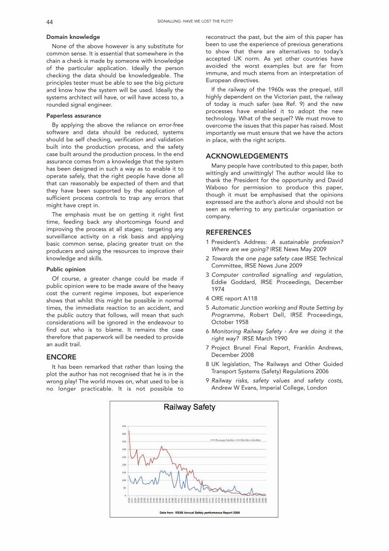
Domain knowledge
None of the above however is any substitute forcommon sense. It is essential that somewhere in thechain a check is made by someone with knowledgeof the particular application. Ideally the personchecking the data should be knowledgeable. Theprinciples tester must be able to see the big pictureand know how the system will be used. Ideally thesystems architect will have, or will have access to, arounded signal engineer.
Paperless assurance
By applying the above the reliance on error-freesoftware and data should be reduced, systemsshould be self checking, verification and validationbuilt into the production process, and the safetycase built around the production process. In the endassurance comes from a knowledge that the systemhas been designed in such a way as to enable it tooperate safely, that the right people have done allthat can reasonably be expected of them and thatthey have been supported by the application ofsufficient process controls to trap any errors thatmight have crept in.
The emphasis must be on getting it right firsttime, feeding back any shortcomings found andimproving the process at all stages; targeting anysurveillance activity on a risk basis and applyingbasic common sense, placing greater trust on theproducers and using the resources to improve theirknowledge and skills.
Public opinion
Of course, a greater change could be made ifpublic opinion were to be made aware of the heavycost the current regime imposes, but experienceshows that whilst this might be possible in normaltimes, the immediate reaction to an accident, andthe public outcry that follows, will mean that suchconsiderations will be ignored in the endeavour tofind out who is to blame. It remains the casetherefore that paperwork will be needed to providean audit trail.
ENCOREIt has been remarked that rather than losing the
plot the author has not recognised that he is in thewrong play! The world moves on, what used to be isno longer practicable. It is not possible to
44 SIGNALLING: HAVE WE LOST THE PLOT?
reconstruct the past, but the aim of this paper hasbeen to use the experience of previous generationsto show that there are alternatives to today’saccepted UK norm. As yet other countries haveavoided the worst examples but are far fromimmune, and much stems from an interpretation ofEuropean directives.
If the railway of the 1960s was the prequel, stillhighly dependent on the Victorian past, the railwayof today is much safer (see Ref. 9) and the newprocesses have enabled it to adopt the newtechnology. What of the sequel? We must move toovercome the issues that this paper has raised. Mostimportantly we must ensure that we have the actorsin place, with the right scripts.
ACKNOWLEDGEMENTSMany people have contributed to this paper, both
wittingly and unwittingly! The author would like tothank the President for the opportunity and DavidWaboso for permission to produce this paper,though it must be emphasised that the opinionsexpressed are the author’s alone and should not beseen as referring to any particular organisation orcompany.
REFERENCES1 President’s Address: A sustainable profession?
Where are we going? IRSE News May 2009
2 Towards the one page safety case IRSE TechnicalCommittee, IRSE News June 2009
3 Computer controlled signalling and regulation,Eddie Goddard, IRSE Proceedings, December1974
4 ORE report A118
5 Automatic Junction working and Route Setting byProgramme, Robert Dell, IRSE Proceedings,October 1958
6 Monitoring Railway Safety - Are we doing it theright way? IRSE March 1990
7 Project Brunel Final Report, Franklin Andrews,December 2008
8 UK legislation, The Railways and Other GuidedTransport Systems (Safety) Regulations 2006
9 Railway risks, safety values and safety costs,Andrew W Evans, Imperial College, London
45SIGNALLING: HAVE WE LOST THE PLOT?
DiscussionSummary of discussion of paper by E. Goddardentitled “Signalling, Have We Lost the Plot?” given on11th November 2009.
The discussion was opened by W. Coenraad(Movares) who thanked the speaker for an interestingand thought provoking paper. Referring to his timespent on the ITC with visits to various countries, heasked what advice he could give to avoid the“English” disease.
E. Goddard recognized that the different culturesdo impact on the safety process; some places have astricter observance of the rules making the processsimpler because there is then no need to question ifthe rules have been followed. In terms of basic safetystandards, such as accessing the track, it is often mucheasier to do this elsewhere indicating that maybe thesituation is too onerous in the UK; if you review theoverall level of safety of the various railways, theresults are very similar so perhaps we need to look atthose differences.
M. Savage (Savoir Ltd) observed that there werefew references to costs or affordability in the paperbut looking at the railway safety graph, noted that theoverall picture was one of a relatively steady natureindicating that the overall impact of the safetyassurance processes that have been implementedhave achieved very little for a great deal ofexpenditure.
E. Goddard pointed out that statistics could alwaysbe used to argue a point and you could question if theincrease in safety was value for money against howthat had been achieved. He believed thatfundamentally the railway is safe but thought thatthere was a need to improve the safety of the railway,not by assurance but by designing it safe in the firstplace. He also believed that abolition of the safetyassurance processes would not keep the railway assafe as it is now; there does need to be some way ofensuring that people are working correctly butperhaps the balance is wrong and needs to bereviewed because of the expense.
D. Jeffrey (Invensys Rail) noted that he not heardthe words “responsibility” or “proportionality”mentioned; all risks being treated as the highest withnobody prepared to take responsibility.
E. Goddard pointed out that trust had to be earnedbut risks do need to be identified at the outset andthen treated in proportion to that particular risk withan emphasis on eliminating the biggest risks anddemonstrating that that had been done.
D. Waboso (LUL) believed that the industry was indanger of pricing itself out of existence andquestioned why it was so difficult to simulate,resulting in numerous tests on the railway itself, andalso why we cannot get products “right first time”.
E. Goddard didn’t think that enough was investedin simulators and modelling before defining thecriteria, building the product and then checking it hasbeen constructed as designed, however, for thosesimulators that do exist, there are still problems andthis does need to be investigated to ensure testing
time is the minimum possible. He was in completeagreement that products need to be “right first time”.
M. Dobell (Rolling Stock Engineer) confirmed thatthere were the same issues within the rolling stockdiscipline but the absolute key has to be “right firsttime”. Taking tried and tested building blocks, ratherthan developing a job in a project environment isessential otherwise you are unsure if you are thenvalidating the product, its development or just thebuild quality.
D. Mills (retired) asked about the development ofyoung engineers and how the Institution can movethis forward. He also noted that the reopened LTMuseum now has no signalling equipment on displayand wondered what had happened to theengineering style periodicals that used to bepublished.
E. Goddard explained that the signallingequipment was not now displayed because thoughtswere that the public were not interested inengineering any more; this is a real concern. Hethought that the Institution could possibly be doingmore to try and “sell” engineering to the youngergeneration.
R. Short (WS Atkins) didn’t believe that it was truethat safety assurance never found anything but withthe (safety) process not starting early enough,problems found at that (late) stage of the projectcould only justify a change if of a very major nature.Any actions would then have to be retrospective,expensive and potentially cause delays which oftenresults in either living with the defect or introducingsome sort of safety related application condition. Hethought we should be looking to replace the safetycase by an audit trail of the safety assurance processwhich continues through the life of the system; thismight even achieve the one page safety case if it wassimply an index of the filing system of this record!
E. Goddard agreed that the safety assurance wasthere to put things right and should be done from thebeginning. He also didn’t think that all of the specificdetails were needed in a safety case if they had beenrecorded and filed as the process continued givingconfidence in what had been undertaken.
A. Bourne (Tubelines) observed that the suppliersoften possess a simulator for their product but thereneeds to be collaboration with the infrastructureowner, who understands the environment in which itis to work, to produce a more realistic simulator. Hethen asked what forum could be utilised that canresolve the problem of the plethora of processes thatis crippling the industry.
E. Goddard had an idea that if simulators hadstandardised interfaces, there may be a way forwardeven though this might require some expenditure. Hewas unsure how the industry could resolve thedifficulties it was facing but knew that it must,somehow, to prevent the “disease” spreading.
R. Blackadder (Siemens) asked if we take thetechnology too far rather than taking a pragmaticapproach that might cost less.
E. Goddard thought that you had to look at thelevel of application and also consider the desire toalways utilise the latest technology rather than usingtried and tested equipment and techniques.
R. Lockett (European Railway Agency) paraphrasedthat the message was to get the product “right firsttime”, and that includes the safety. He also explainedthat previous thinking had been that quality andsafety were the same thing and that finished workinspection was a poor way of assuring quality. Youneed to have good processes and he thought itappeared that we are now doing all of these activitiesbut not doing any of them particularly well.
E. Goddard believed that it was probably “horsesfor courses” but it was still essential to recognise thatpeople do make mistakes. Whilst with hardware youcan undertake inspections, it is impossible to fully testsoftware and hence there is a place for bothinspection and audit. This is more so betweencompanies where you may end up with some form ofoverlapping processes but again it is important toconcentrate on the bigger elements of risk. It is alsosensible to compare processes between the differentdisciplines to get the best of both worlds.
C. Thompson (Honorary Fellow) quoted that “goodorder always requires a great deal of energy tomaintain it” believing this particularly applied to goodprocesses that had probably been neglected. He alsoreferred to the Nimrod report as an example of thefundamental reasons and importance for havingsafety cases; the original idea behind them was thatthe chief designer should explain his safety principlesas he undertook the design - the idea of anindependent body doing this was never considered.The industry has allowed all of these processes to befragmented and he didn’t believe that manycompanies understood the totality of the process nowand it was this that needed to be reversed.
E. Goddard also thought that it was now difficult toget an overall picture but the designer still needs toexpress what they are going to do and why theybelieve it is safe although discipline is needed to dothis.
F. Heijnen (IRSE President) pointed out that we arelosing skills from the industry and he wondered whenthe situation would become impossible to manage.
E. Goddard thought that supply and demand wouldbe a catalyst and encourage people into the industry,however, in the short term the situation is of someconcern that may actually lead to a review of theprojects that can be resourced.
Cy Porter (Past President) noted that theimportance of money was rarely discussed but wasoften just as, if not more important than safety cases;without a good business case you don’t get started inthe first place! He thought that the training ofengineers to include some form of business andcommercial awareness was now needed and wasprobably more important than ever; this is particularlyrelevant when the impression given today is thatengineering is expensive.
E. Goddard stated that he did receive some trainingin economics during his apprenticeship. He thoughtthat engineers had now given the impression that notonly was engineering expensive, but we also madethings more complicated than they need be;engineers need to simplify things and provide valuefor money. He considered this is a result of the trainingprovided; civil engineers are trained in contractmanagement whereas electrical engineers tend not tobe and this shortfall needs to be remedied.
A. Love (Thales) had seen the benefits of simulationbut wondered how its use was to be encouraged. Healso questioned how we get Signal Engineers torealise the importance of the ConfigurationManagement Process and finally wondered how thechangeover and interface issues can be given moreemphasis.
E. Goddard believed that the transfer of experiencefrom other industries is essential but we need to learnto do these ourselves. He thought that thefundamental principle of interfacing with the existingrailway was one of the major challenges to be faced.
F. Heijnen (IRSE President) thanked the author forhis interesting paper, which had given much food forthought; getting new people into the industry andreviewing how we do things was essential.
(Produced by Peter Grant)
46 SIGNALLING: HAVE WE LOST THE PLOT?
47
INTRODUCTIONAs we approach the centenary of the IRSE, one of
the benefits of modern technology is that we can allhave 100 years of the Institution’s proceedings atour fingertips on a DVD, and this makes it mucheasier for prospective authors to check up on thethoughts of our predecessors on the subject matterin question. From the earliest days, speakers havealluded to the role of the signal engineer indelivering efficient operation of the railways, but inthe main this has been considered in the context ofproviding the minimum constraints consistent withsafety. As far as I can tell this is the first paper to lookspecifically at providing the train driver withadditional information to optimise train movementswithin the limits imposed by the signallingmovement authorities.
With a view to simplicity and safety, signallingsystems tell the driver how far and fast the train cansafely proceed within the allocated movementauthority, but the wider traffic management picture ishidden from the driver. With the informationprovided, and pressure to achieve high levels ofpunctuality, the natural tendency for the train driver is
to get to the end of the movement authority as soonas possible. If this results in an early arrival or anothertrain is running late, in many cases the train has tostop and then start again when the movementauthority is eventually extended. If we can avoid thisscenario by regulating the train speed earlier in thejourney there are several potential benefits:
• Capacity improvements by running throughjunctions at higher speed;
• Safety improvements through fewer redsignal approaches;
• Maintenance savings through reduced brakewear on the train;
• Energy savings and reduced carbonemissions.
It is the last of these benefits that I allude to in mytitle, and which has brought this topic to the top ofthe research agenda. Through the inherentmechanical efficiency of the steel wheel on the steelrail, and the flexibility of electric traction to makeuse of a wide range of primary energy sources,railways have a natural advantage over road and airtransport modes in the modern world, wherereduction in carbon emissions has become a priority.However in recent years many of the trends inrolling-stock design have been pushing up energy1 The author is with DeltaRail Group Limited.
The Sustainable RailwayUse of Advisory Systems for Energy Savings
Ian Mitchell1
Technical Meeting of the Institutionheld at
1 Birdcage Walk, London
Wednesday 9th December 2009The President, Mr F Heijnen, in the chair.
51 members and visitors were in attendance. There were apologies for absence from Martin Govas and Ken Burrage. It was proposed by Mr K Walter, seconded by Mr J Tilly and carried that the minutes
of the technical meeting held on 11 November 2009 be taken as read and they were signed by Mr Heijnen as a correct record. The Chairman then invited any new members present for the first time since their election to come forward to be introduced to the meeting. Mr Vivich
Silapasoonthorn (London Underground) and Mr Marco Lüthi (Systransis AG, Switzerland) came forward to be introduced to warm applause. The Chairman then introduced Ian Mitchell (Professional Head of Signalling, DeltaRail Ltd) and asked him to present his paper “Sustainable Railway: Use of
Advisory Systems for Energy Savings”Mr Mitchell started by stating that the work covered within the paper was part of a research project funded by RSSB. He then described the concepts of
energy conversion and dissipation, and the various driving strategies used by trains and their impact on the use of energy. He went on to outline therequirements for a driver advisory system and described different potential architectures for such a system. He went on to describe the technology choices fortrain location/communications and the train installation requirements. He showed a video of an American 14000 ton freight train fitted with one proprietarysystem. He then listed some of the human factors issues and options for automatic train operation, and gave figures for potential energy savings. Results sofar were slightly disappointing in that there did not seem to be a financial case for control centre based solutions. He finished by outlining the outstandinghuman factors and interface standards issues, and the next steps in the research programme.
Following the presentation, the discussion was opened by Jacques Poré (Alstom, France - Past President). Peter Gould (DeltaRail), David Bradley(independent consultant), Peter Halliwell (Network Rail), Marco Lüthi (Systransis AG), Melvyn Nash (independent consultant), and Stuart Bamforth (InvensysRail) all took part in the discussion.
The Chairman then thanked the speaker and proposed a vote of thanks to him for his very interesting paper which covered a different area of train controlfrom the subjects normally discussed at the Institution and which had stimulated some interesting questions. He then presented him with a commemorativeplaque customarily awarded to the author of a London paper.
Mr Heijnen thanked members and visitors for their attendance and their contribution, and then in closing the meeting at 2000, stated that the next meetingin London would be a technical meeting held on the 13 January 2010 when Mr Joeren Nederlof would present a paper entitled “Level Crossings in theNetherlands”. He then wished everyone a peaceful Christmas and Happy New Year.
consumption. For example: trains have got heavieras a result of improved crashworthiness design, andwaste retention toilets; auxiliary powerconsumption is up as a result of improvements in airconditioning and other passenger amenities; andmuch more powerful traction systems are installedto give reduced journey times.
It is now clearly recognised that, with globalwarming a reality and “peak oil” on the horizon, therailways need to improve their act and considerenergy efficiency as a key element in design andoperation of railway systems. Our rolling stockelectrical and mechanical engineering colleaguesare making great strides in this direction.Regenerative braking is now widespread on modernelectric trains, and the next generation of rollingstock is promising significant weight reductionswithout loss of comfort or crashworthiness. We needto make similar contributions from improving theway we operate the railway.
TIMETABLE MARGINSEnergy efficiency in railway operation has to be
constrained by other business requirements, and byand large these are captured in the timetable. Thetimetable for a mixed traffic railway network isinevitably a compromise between journey time,frequency and regularity of service, capacity andreliability. At the moment, in the UK at least, energyefficiency is not a direct consideration in determiningthe timetable. This may change in future, but theother business requirements will continue todominate, so the goal of energy-efficient operationwill generally be to optimise energy consumptionwithin given timetable constraints. In other words,we wish to maintain the departure, arrival andpassing times specified in the timetable, andoptimise the journey profile (speed versus distance)for the train within these constraints.
Of course, if a timetable is designed to match theminimum journey time that the train can achievebetween the timing points precisely, the driver has todrive flat-out all the way and there is no potential forenergy saving. In practice timetables always include atime margin which is made up of two components,explicit allowances and hidden slack.
Explicit allowances are additional time insertedinto the schedules before certain timing points. OnNetwork Rail in the UK, there are three types ofallowances.
• Engineering allowances are added to allowsome extra running time to compensate fortemporary speed restrictions imposed by thecivil engineer due to track defects ormaintenance work. The allowance is based onan assumption of the number, severity andlength of the temporary speed restrictionsthat are expected at any one time.
• Pathing allowances are added at stations andjunctions where it is recognised in thetimetable planning that two trains are goingto conflict, so that the resulting delay is takeninto account in the subsequent timings for thetrain that has not been given priority.
• Performance allowances are added to allowrecovery from delays earlier in the journey.These are often added at the end of a journeyso as to improve the punctuality statistics ofthe railway undertaking.
Hidden slack is the margin between the sectionalrunning times used in planning the timetable, andthe actual minimum running time that the train iscapable of achieving. This margin exists for anumber of reasons.
• Sectional running times are rounded to thenearest minute or half minute.
• Sectional running times have not beenupdated to take account of line speed orrolling stock improvements.
• Sectional running times are based on a worst-case assumption of rolling stock performance,e.g. minimum power supply voltage,maximum loading and the slowest vehicles inthe fleet.
The net effect of all these margins is that, for themajority of train services, a train that departs ontime and runs at the maximum permissible speedwill always arrive early. The aim of energy-efficientdriving is to operate the train to a speed profile thatwill exploit these margins to save energy whilstachieving an arrival on time.
ENERGY EFFICIENT SPEED PROFILELeaving aside all the auxiliary loads that are not
concerned with propulsion, the energy input tomove a train can be split as follows.
• Energy conversion – this includes energyinput to lift the train to a higher altitude on anupward gradient, and to accelerate the trainto a higher speed. In principle this energy canbe recovered, when the train loses altitude orspeed.
• Energy dissipation – this includes mechanicaland aerodynamic resistance to movement ofthe train, and inefficiencies in the traction andbraking systems of the train. This energy islost (usually by conversion to heat) and cannotbe recovered.
Because of the inherent efficiency of the steelwheel on steel rail, aerodynamic resistance is thedominating factor in energy dissipation. This ishighly dependent on train speed, which means thatreducing the maximum speed of the train has to bethe main strategy for energy efficient driving. Thismeans that quite a simple driving strategy, with nochanges to acceleration and braking at the start andend of a journey leg, and a suitable “cruising speed”in between, will achieve very significant reductionsin energy consumption.
This strategy is well suited to modern electrictraction systems which have relatively constantefficiency across a range of speed and powersettings, and use regenerative braking to recoverenergy when braking. If regenerative braking is notavailable, or the traction system is inefficient whenoperating at constant speed, a speed profile thatmakes use of coasting will achieve further savings.
THE SUSTAINABLE RAILWAY – USE OF ADVISORY SYSTEMS FOR ENERGY SAVINGS48
For a suburban route with frequent stops this canbe simply made up of acceleration on maximumpower, coasting without power for a significant partof the distance between stations, and then brakingas late as possible. With this model the averagespeed when coasting is equivalent to the “cruisingspeed” in the constant speed strategy. Thedisadvantage of coasting is that the rate ofdeceleration is sensitive to train characteristics,gradients, curvature, and environmental factorssuch as wind speed and direction. This means that,for longer-distance and higher-speed services,calculation of an optimum speed profileincorporating coasting is much more difficult thatfor a simple “cruising speed”.
MODELLING OF BENEFITSThe level of benefits that might be obtained from
adopting an energy efficient speed profile has beencalculated as part of the Rail Safety and StandardsBoard (RSSB) research project T724, “DriverAdvisory Information for Energy Management andRegulation.” The VISION® operational simulationsoftware was used to model a substantial part of themain line railway network in Kent for three hours inthe morning peak. The modelling madecomparisons between three different scenarios:
• a baseline scenario in which train speedsfollow a “professional driving” model basedon current UK driver training, incorporatingmaximum acceleration to full line speed butcautious braking on approach to restrictivesignal aspects and station stops;
• an energy-efficient driving scenario where thetimetable is used to calculate a “cruisingspeed” for each train, aiming to avoid earlyarrival at the next timing point;
• a control centre optimised scenario, wherethe “cruising speed” for each train is adjustedif necessary to avoid predicted junctionconflicts with other trains.
Figure 1 shows speed profiles for the same trainservice running in the baseline and the energyefficient driving scenarios. The reduced maximumspeed on most of the journey legs is clearly visible.The results show that in the absence of any recoveryof energy, for example from regenerative braking,energy efficient driving could save 26% of energy inideal unperturbed operation of the same timetable.If 90% of the energy lost through braking wererecoverable, the energy savings would still be 15%.The additional energy savings in the control centreoptimised scenario were very small.
Of course, if some trains are running late forwhatever reason, they will need to run at full linespeed to recover time and the energy savings willbe reduced. To take this into account, thesimulation was repeated with perturbations tonormal operation deliberately introduced so thatthe overall punctuality in the baseline scenariomatched the average performance for this area inthe last year. As expected this gave a reduction inenergy savings, to 14% without energy recoveryand 8% with.
The modelling also allows conclusions to bedrawn on some of the other impacts of driveradvisory information. The number of red signalapproaches was reduced by 22% in the unperturbedtimetable and 11% in the perturbed timetable. Thiscan be claimed as a safety benefit, since risk of asignal passed at danger (SPAD) is generally taken tobe proportional to the number of red signalapproaches.
DRIVER PERFORMANCERailway operations modelling is inevitably based
on many assumptions, but the most criticalassumptions in this case relate to driver behaviour.The energy savings assume that drivers behave inaccordance with the VISION® professional drivingmodel today and can be guided to achieve theenergy efficient speed profile in future.
In practice, there is a wide variation in drivingstyles today. Our expectation is that most driverswill perform around the professional driving model,but some may already be driving in a more energyefficient way. Figure 2 shows some measurementsmade by Bombardier. The curve on the graph is thetheoretical minimum energy consumption againstjourney time for a route, and the scatter of pointsare actual measurements. This suggests that manydrivers mismanage the margins in timetables withunnecessary acceleration and braking such that theyuse more energy than the theoretical flat-outminimum journey time speed profile for the route.This gives us some confidence that the baselineenergy consumption in the modelling is areasonable average.
The bigger question is how driver behaviour canbe influenced. Training is an obvious opportunityand some railway undertakings are now introducing“eco-driving” as a theme in the refresher trainingthat they deliver to drivers using driver-trainingsimulators, with a calculation of energy consumedon a training run to feed back to drivers.
Training can ensure that drivers are aware of theprinciples of energy efficient driving, and perhapsprovide some tips on how to drive a specific route inideal conditions, but the task of devising andfollowing an energy efficient speed profile is not aneasy one, and after training the driver is left to hisown devices with minimal feedback. The alternativeapproach is to provide the driver with sometechnology to help him in this task, and this is thesubject of the remainder of this paper.
SYSTEM ARCHITECTURE FOR A DRIVERADVISORY SYSTEM
The fundamental requirements for a driveradvisory system (DAS) are:
• to determine the target arrival time for thetrain at stations and junctions that must beachieved to satisfy the published timetableand avoid conflicts with other trains;
• to calculate an energy-efficientspeed/distance profile starting from thecurrent train location and time, to achieve thetarget arrival times along the route;
THE SUSTAINABLE RAILWAY – USE OF ADVISORY SYSTEMS FOR ENERGY SAVINGS 49
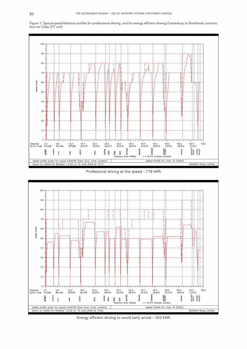
50 THE SUSTAINABLE RAILWAY – USE OF ADVISORY SYSTEMS FOR ENERGY SAVINGS
Figure 1: Typical speed/distance profiles for professional driving, and for energy efficient driving (Canterbury to Shortlands Junction,four-car Class 377 unit)
Professional driving at line speed – 718 kWh
Energy efficient driving to avoid early arrival – 503 kWh
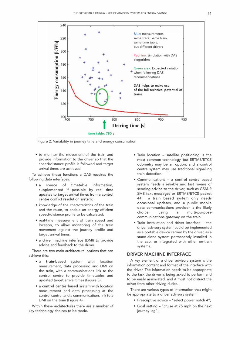
• to monitor the movement of the train andprovide information to the driver so that thespeed/distance profile is followed and targetarrival times are achieved.
To achieve these functions a DAS requires thefollowing data interfaces:
• a source of timetable information,supplemented if possible by real timeupdates to target arrival times from a controlcentre conflict resolution system;
• knowledge of the characteristics of the trainand the route, to enable an energy efficientspeed/distance profile to be calculated;
• real-time measurement of train speed andlocation, to allow monitoring of the trainmovement against the journey profile andtarget arrival times;
• a driver machine interface (DMI) to provideadvice and feedback to the driver.
There are two main architectural options that canachieve this:
• a train-based system with locationmeasurement, data processing and DMI onthe train, with a communications link to thecontrol centre to provide timetables andupdated target arrival times (Figure 3);
• a control centre based system with locationmeasurement and data processing at thecontrol centre, and a communications link to aDMI on the train (Figure 4).
Within these architectures there are a number ofkey technology choices to be made.
THE SUSTAINABLE RAILWAY – USE OF ADVISORY SYSTEMS FOR ENERGY SAVINGS 51
• Train location – satellite positioning is themost common technology, but ERTMS/ETCSodometry may be an option, and a controlcentre system may use traditional signallingtrain detection.
• Communications – a control centre basedsystem needs a reliable and fast means ofsending advice to the driver, such as GSM-RSMS text messages or ERTMS/ETCS packet44; a train based system only needsoccasional updates, and a public mobiledata communications provider is the likelychoice, using a multi-purposecommunications gateway on the train.
• Train installation and driver interface – thedriver advisory system could be implementedas a portable device carried by the driver, as astand-alone system permanently installed inthe cab, or integrated with other on-trainsystems.
DRIVER MACHINE INTERFACEA key element of a driver advisory system is the
information content and format of the interface withthe driver. The information needs to be appropriateto the task the driver is being asked to perform andto be easily assimilated, and it must not distract thedriver from other driving duties.
There are various types of information that mightbe appropriate to a driver advisory system:
• Prescriptive advice – “select power notch 4”;
• Goal setting – “cruise at 75 mph on the nextjourney leg”;
Figure 2: Variability in journey time and energy consumption
Blue: measurements,same track, same train,same time table,but different drivers
Red line: simulation with DASalogorithm
Green area: Expected variationwhen following DASrecommendations
DAS helps to make useof the full technical potential oftrains.
time table: 780 s
Driving time [s]
Ene
rgy
cons
umpt
ion
[kW
h]
240
220
200
180
160
140
120
100700 750 800 850 900 950
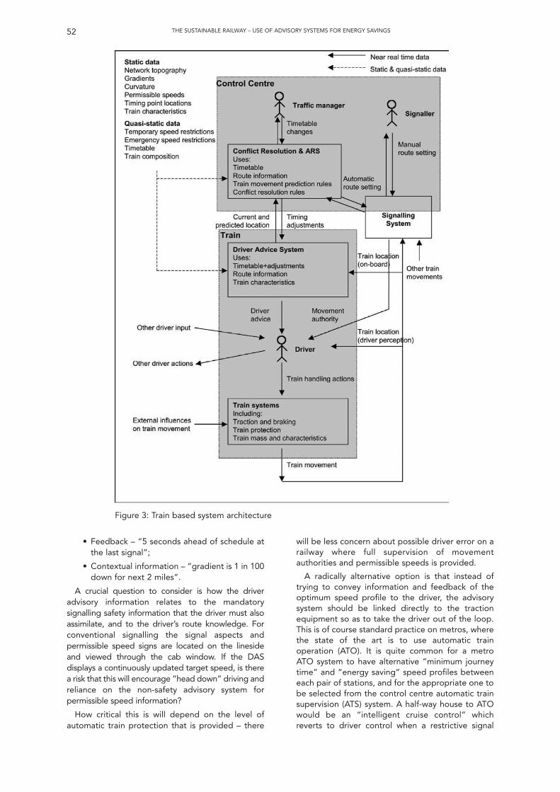
THE SUSTAINABLE RAILWAY – USE OF ADVISORY SYSTEMS FOR ENERGY SAVINGS52
• Feedback – “5 seconds ahead of schedule atthe last signal”;
• Contextual information – “gradient is 1 in 100down for next 2 miles”.
A crucial question to consider is how the driveradvisory information relates to the mandatorysignalling safety information that the driver must alsoassimilate, and to the driver’s route knowledge. Forconventional signalling the signal aspects andpermissible speed signs are located on the linesideand viewed through the cab window. If the DASdisplays a continuously updated target speed, is therea risk that this will encourage “head down” driving andreliance on the non-safety advisory system forpermissible speed information?
How critical this is will depend on the level ofautomatic train protection that is provided – there
will be less concern about possible driver error on arailway where full supervision of movementauthorities and permissible speeds is provided.
A radically alternative option is that instead oftrying to convey information and feedback of theoptimum speed profile to the driver, the advisorysystem should be linked directly to the tractionequipment so as to take the driver out of the loop.This is of course standard practice on metros, wherethe state of the art is to use automatic trainoperation (ATO). It is quite common for a metroATO system to have alternative “minimum journeytime” and “energy saving” speed profiles betweeneach pair of stations, and for the appropriate one tobe selected from the control centre automatic trainsupervision (ATS) system. A half-way house to ATOwould be an “intelligent cruise control” whichreverts to driver control when a restrictive signal
Figure 3: Train based system architecture
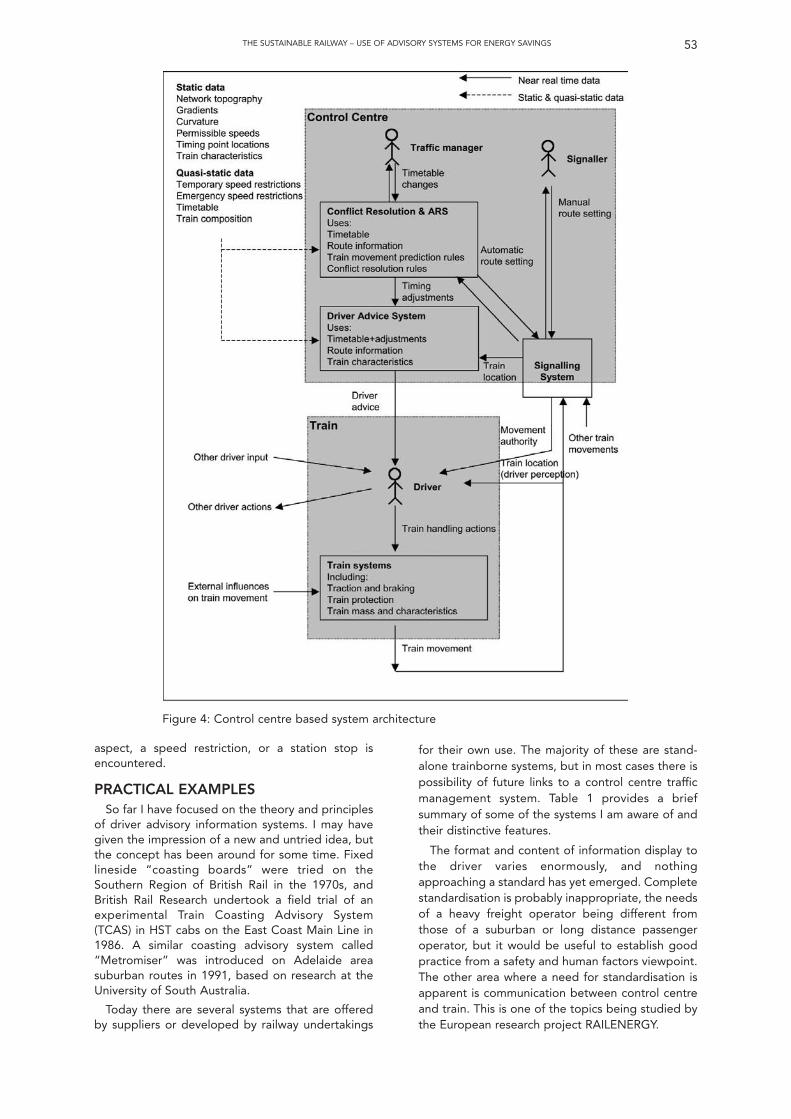
aspect, a speed restriction, or a station stop isencountered.
PRACTICAL EXAMPLESSo far I have focused on the theory and principles
of driver advisory information systems. I may havegiven the impression of a new and untried idea, butthe concept has been around for some time. Fixedlineside “coasting boards” were tried on theSouthern Region of British Rail in the 1970s, andBritish Rail Research undertook a field trial of anexperimental Train Coasting Advisory System(TCAS) in HST cabs on the East Coast Main Line in1986. A similar coasting advisory system called“Metromiser” was introduced on Adelaide areasuburban routes in 1991, based on research at theUniversity of South Australia.
Today there are several systems that are offeredby suppliers or developed by railway undertakings
53THE SUSTAINABLE RAILWAY – USE OF ADVISORY SYSTEMS FOR ENERGY SAVINGS
for their own use. The majority of these are stand-alone trainborne systems, but in most cases there ispossibility of future links to a control centre trafficmanagement system. Table 1 provides a briefsummary of some of the systems I am aware of andtheir distinctive features.
The format and content of information display tothe driver varies enormously, and nothingapproaching a standard has yet emerged. Completestandardisation is probably inappropriate, the needsof a heavy freight operator being different fromthose of a suburban or long distance passengeroperator, but it would be useful to establish goodpractice from a safety and human factors viewpoint.The other area where a need for standardisation isapparent is communication between control centreand train. This is one of the topics being studied bythe European research project RAILENERGY.
Figure 4: Control centre based system architecture
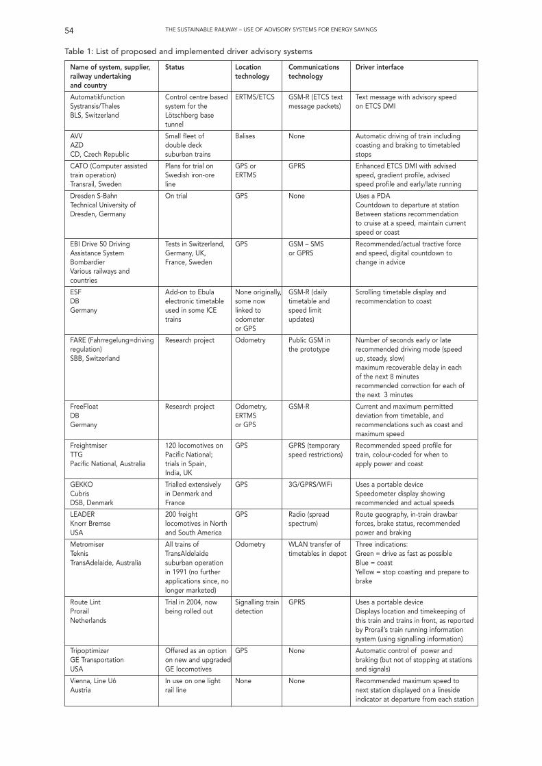
54 THE SUSTAINABLE RAILWAY – USE OF ADVISORY SYSTEMS FOR ENERGY SAVINGS
Name of system, supplier, Status Location Communications Driver interfacerailway undertaking technology technologyand country
Automatikfunction Control centre based ERTMS/ETCS GSM-R (ETCS text Text message with advisory speed Systransis/Thales system for the message packets) on ETCS DMIBLS, Switzerland Lötschberg base
tunnel
AVV Small fleet of Balises None Automatic driving of train includingAZD double deck coasting and braking to timetabledCD, Czech Republic suburban trains stops
CATO (Computer assisted Plans for trial on GPS or GPRS Enhanced ETCS DMI with advisedtrain operation) Swedish iron-ore ERTMS speed, gradient profile, advisedTransrail, Sweden line speed profile and early/late running
Dresden S-Bahn On trial GPS None Uses a PDATechnical University of Countdown to departure at stationDresden, Germany Between stations recommendation
to cruise at a speed, maintain current speed or coast
EBI Drive 50 Driving Tests in Switzerland, GPS GSM – SMS Recommended/actual tractive forceAssistance System Germany, UK, or GPRS and speed, digital countdown toBombardier France, Sweden change in adviceVarious railways and countries
ESF Add-on to Ebula None originally, GSM-R (daily Scrolling timetable display andDB electronic timetable some now timetable and recommendation to coastGermany used in some ICE linked to speed limit
trains odometer updates)or GPS
FARE (Fahrregelung=driving Research project Odometry Public GSM in Number of seconds early or lateregulation) the prototype recommended driving mode (speedSBB, Switzerland up, steady, slow)
maximum recoverable delay in each of the next 8 minutesrecommended correction for each ofthe next 3 minutes
FreeFloat Research project Odometry, GSM-R Current and maximum permittedDB ERTMS deviation from timetable, andGermany or GPS recommendations such as coast and
maximum speed
Freightmiser 120 locomotives on GPS GPRS (temporary Recommended speed profile for TTG Pacific National; speed restrictions) train, colour-coded for when toPacific National, Australia trials in Spain, apply power and coast
India, UK
GEKKO Trialled extensively GPS 3G/GPRS/WiFi Uses a portable deviceCubris in Denmark and Speedometer display showing DSB, Denmark France recommended and actual speeds
LEADER 200 freight GPS Radio (spread Route geography, in-train drawbarKnorr Bremse locomotives in North spectrum) forces, brake status, recommendedUSA and South America power and braking
Metromiser All trains of Odometry WLAN transfer of Three indications:Teknis TransAldelaide timetables in depot Green = drive as fast as possibleTransAdelaide, Australia suburban operation Blue = coast
in 1991 (no further Yellow = stop coasting and prepare toapplications since, no brakelonger marketed)
Route Lint Trial in 2004, now Signalling train GPRS Uses a portable deviceProrail being rolled out detection Displays location and timekeeping of Netherlands this train and trains in front, as reported
by Prorail’s train running information system (using signalling information)
Tripoptimizer Offered as an option GPS None Automatic control of power and GE Transportation on new and upgraded braking (but not of stopping at stations USA GE locomotives and signals)
Vienna, Line U6 In use on one light None None Recommended maximum speed to Austria rail line next station displayed on a lineside
indicator at departure from each station
Table 1: List of proposed and implemented driver advisory systems
PROSPECTS FOR APPLICATION INGREAT BRITAIN
There have been a number of shortdemonstrations of driver advisory systemsorganised by suppliers in association with Britishtrain operating companies, but the main focus forstudy of this technology at present is an RSSBresearch project known as “T724 Driver AdvisoryInformation for Energy Management andRegulation”. This has brought together a number ofstakeholders with a range of interests in the topic:
• the Department for Transport, who wish toreduce the carbon footprint of the railindustry;
• passenger and freight train operatingcompanies, who wish to reduce their energycosts;
• Network Rail, who wish to optimise trafficflow on congested areas of the network;
• rolling stock companies, who want tomaximise the whole-life energy efficiency oftheir assets.
The contract to undertake this research wasawarded to DeltaRail Group Limited, with supportfrom Human Engineering Limited and BAE Systems.The work is being undertaken in stages.
Stage 1 was undertaken in 2008. Outputs at thisstage were: information gathered on existingsystems; review of the main-line railway context inBritain including engineering, operational andsocietal issues, human factors and safety analysis,definition of options for system architecture, traininstallation and driver interface; and a preliminarybusiness case.
Stage 2 took place in 2009, and included ananalysis of timetable margins, modelling of energysavings and other impacts, further work onalternative system architectures, a review of theimpact of gaps in GPS and mobile radio coverage, adefinition of data interface requirements andplanning of cab simulator trials.
As with other RSSB research projects, the fullformal reports from each stage are made availableon the RSSB web site following stakeholder review.The conclusions that have been reached in theproject so far are as follows.
• There are undoubtedly significant energysavings to be obtained from energy-efficientdriving for a wide range of types of passengerand freight services on the UK main-line
railway network. Almost all the benefit can beobtained from a system that manages eachtrain individually to its pre-planned timetable,with only marginal additional benefits from amore sophisticated system with activemanagement of conflicts from the controlcentre.
• There will be a secondary benefit to safetythrough reduced numbers of red signalapproaches, but the modelling so far hasfailed to identify any widespread performanceand capacity benefits, and there may even bea small increase in average train lateness as aresult of aiming for arrival on time rather thanearly.
• It is likely that a positive business case can bemade for introducing a driver advisorysystem, but this will be sensitive toassumptions made regarding what level ofenergy saving could be achieved simplythrough better driver training, to the cost oftrain fitment and to the monetary value puton performance impact.
• The technology exists to achieve a workabledriver advisory system, but the wide range ofdriver interfaces on offer from existingsystems is symptomatic of a lack offundamental human factors research. This isof particular concern for an application onNetwork Rail where the standard trainprotection system AWS/TPWS does notprovide continuous speed supervision.
It is hoped that funds will be available in 2010 totake the project forward to Stage 3 which willinclude cab simulator trials of alternative driverinterface information and formats, with the aim ofunderstanding how best to give the driver anadditional information source whilst avoidingdistraction from primary safety related tasks.
ACKNOWLEDGEMENTSI would like to thank Rail Safety and Standards
Board and DeltaRail Group Limited for permissionto present this paper and make use of results fromthe T724 research project. I would also like to thanka number of the suppliers of the driver advisorysystems I have listed in Table 1 for information theyhave provided, and in particular Bombardier forproviding the graph in Figure 2. However I am solelyresponsible the opinions expressed in the paper,and any errors or misrepresentations that I haveintroduced.
55THE SUSTAINABLE RAILWAY – USE OF ADVISORY SYSTEMS FOR ENERGY SAVINGS
56 THE SUSTAINABLE RAILWAY – USE OF ADVISORY SYSTEMS FOR ENERGY SAVINGS
DiscussionSummary of discussion of paper by I. Mitchellentitled “Sustainable Railway: Use of AdvisorySystems for Energy Savings” given on 9thDecember 2009.
The discussion was opened by J Poré (Alstom)who thanked the speaker for his interesting paperthat was not just confined to the UK; he observedthat the technology was already in use elsewhere inthe world and allowed for better utilisation andregulation such as “meet and pass”. He wondered ifit would be possible to use the technology toreward those staff who drive economically andasked the speaker to expand on the sectors wherethe technology could be utilised.
I. Mitchell explained that the Train OperatingCompanies (TOC’s) were taking the issue of energyconsumption seriously with some fitting meters andothers analysing the On Train Monitoring Recordersand giving feedback to the driving staff wherenecessary. This could therefore, in theory, be usedto encourage better driving techniques until the useof ATO supersedes the human input. He admittedthat the paper had focussed chiefly on the mainlinesystem but thought that dwell times were often thekey to consistent performance. He believed thatsome of the existing timetable recovery timecatered for extended dwell times which would belost if right-time arrivals were adhered to. One itemthat had not been investigated, but was critical tothe operators’ costs was looking at the peakdemand for electricity and optimising thoserequirements. He confirmed that the “meet andpass” philosophy had been in use in North Americafor some time and that although the driver interfacewas often through a radio message, it would bepossible to integrate this with some form of MMI toprovide a continuous display. Finally, he describedan Australian system that allows the driver to inputa target arrival time with the system calculating themost efficient method of driving to achieve this.
P. Gould (Delta Rail) asked if any research hadbeen carried out by the TOCs to determine whichdriver in a particular depot drove more efficiently.
I. Mitchell acknowledged that this informationexisted, and was illustrated in figure 2 in the paper;this data is been used to influence drivingtechniques and provide feedback to the staff. Thespeaker thought that if an advisory system wasfitted in the cab, then the results in figure 2 wouldtend to “cluster” rather than be “scattered”.
D. Bradley (Independent Engineer) thought thatthe paper was the next step in the evolution ofsignal engineering with a move towards trafficmanagement and efficient operation of the railway.Whilst timetable parameters were within the remitof the TOCs, signalling information could be utilisedto predict and prevent conflicts, all of which wouldresult in the saving of energy. He thought that thebusiness case would not necessarily be easilydemonstrated with the current delay regime, andthe consequent financial implications, and he askedfor the speakers thoughts on what steps the signal
engineer could take to assist in this including howfar away from conflict points should these “conflictresolution decisions” be made.
I. Mitchell clarified that energy savings had beencalculated on a number of approximations with amore systematic model being developed toproduce the final results. He agreed that there wasa real issue with the current performance regimeand providing a business case to justify theeconomies was difficult although the purchase offuel was a very apparent outgoing for a company;there was a real enthusiasm within the TOCs, butnot so within Network Rail, who feel that some ofthe inherent, but hidden, timetable errors could berevealed if trains were driven at the optimum level.With critical junctions, he felt that conflictmanagement simulation had been shown to providebenefits but the traffic management tools had stillto be developed together with the driver advisorysystems to realise the full potential of this work.
P. Halliwell (Network Rail) referred to the slack inthe timetable, some of which is specificallydesigned, and other quantisation errors, and heasked if the research had investigated thepossibilities associated with tightening up on theslack and errors with a view to increasing capacitybalanced against the increased risk of perturbation.
I. Mitchell acknowledged that it had beenconsidered but had not been taken further. Hepointed out that the timetable was a very complexoptimisation process to achieve all of the conflictingdemands and requirements and thought it wassurprising that a working timetable had actually everbeen produced! He confirmed that energyconsumption had never been a factor considered intheir production but this research has shown upsome of these discrepancies that are inherentlypresent. He thought that the additional capacitywas probably only available at certain specific pointson the network. Looking forward, he felt it waspossible that some of these issues could beconsidered in the future but believed that it wouldbe a real challenge to achieve this with any furtheroptimisation of the timetable.
M. Lüthi (Systransis AG) was surprised that theresults did not show a real reduction in attributeddelays. He also explained that showing speed to thedriver increased efficiency and he asked if thespeaker was aware of any other country that did thiswithout some form of ATP system.
I. Mitchell believed that some of the systems thatdisplayed speed to the driver did not have a form ofcontinuous ATP but there was nervousness, in theUK, about displaying speed under thesecircumstances although there had, however, beensome interest in presenting some form oftimekeeping advice to the driver.
M. Nash (Independent Consultant) was unclearabout where the business case was for providing anelectrified railway with the separation of theinfrastructure from the train operating companies.
I. Mitchell agreed that it is not so apparent; theTOCs pay Network Rail for their electricity throughtheir track access charges whilst Network Rail paysthe electricity suppliers for the energy supplied.Should one company apply energy saving measuresthen, in theory, all TOCs would benefit and there isa thought that in the future there may be a form of“billing” for each train with the TOC billed for theenergy actually consumed.
F. Heijnen (IRSE President) confirmed that thereare meters fitted to all trains in Spain to determinethe cost of the energy consumed - the InfrastructureOwner simply “transports” the energy from sub-station to the train.
I. Mitchell observed that this can lead to thesituation where the sum of the energy used by eachtrain does not actually equate to the total energysupplied and leads to the problem of who then paysfor the difference!
S. Bamforth (Invensys) believed that any (historic)slack in the timetable had been taken up bydefensive driving techniques and extended stationdwell times, except for the last few minutes addedbetween the final two stations, and he asked if the
results obtained had been normalised against realityrather than theoretical. He pointed out that theimplementation of ETCS would provide all of theon-board data required, together with the benefit ofATP necessary to display the advisory speeds, andsuggested that this was a key element.
I. Mitchell was not convinced that normalisation,in his experience, was necessarily required in allcases; all routes being different and the use of realdata was needed. If ETCS was here today, he agreedit would provide a superb platform for overlayingthese advisory systems but that is not reality andhence the research was undertaken to see whatcould be done in the short term. One additionalproblem with modifying ETCS, which is a SIL 4system, is the affect of the modifications required toprovide the non-critical advisory informationneeded by the TOCs.
F. Heijnen (IRSE President) thanked the author forhis interesting paper noting that something needsto be done to ensure the future for the followinggenerations.
(Produced by Peter Grant)
57THE SUSTAINABLE RAILWAY – USE OF ADVISORY SYSTEMS FOR ENERGY SAVINGS
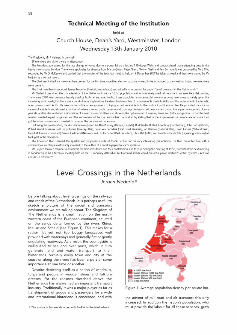
Before talking about level crossings on the railwaysand roads of the Netherlands, it is perhaps useful tosketch a picture of the social and transportenvironment we are talking about. The Kingdom ofThe Netherlands is a small nation on the north-western coast of the European continent, situatedon the sandy delta formed by the rivers Rhine,Meuse and Scheld (see Figure 1). This makes for arather flat yet not too boggy landscape, wellprovided with waterways and generally flat or gentlyundulating roadways. As a result the countryside iswell-suited to sea and river ports, which in turngenerate land and water transport to theirhinterlands. Virtually every town and city at thecoast or along the rivers has been a port of someimportance at one time or another.
Despite depicting itself as a nation of windmills,tulips and people in wooden shoes and folkloredresses, for the reasons sketched above theNetherlands has always had an important transportindustry. Traditionally it was a major player as far astranshipment of goods and passengers for a wideand international hinterland is concerned, and with
58
Technical Meeting of the Institutionheld at
Church House, Dean’s Yard, Westminster, London
Wednesday 13th January 2010The President, Mr F Heijnen, in the chair.
39 members and visitors were in attendance. The President apologised for the late change of venue due to a power failure affecting 1 Birdcage Walk, and congratulated those attending despite the
heavy snow around London. There were apologies for absence from Martin Govas, Peter Grant, Melvyn Nash and Ken Burrage. It was proposed by Mr J Tilly,seconded by Mr D McKeown and carried that the minutes of the technical meeting held on 9 December 2009 be taken as read and they were signed by MrHeijnen as a correct record.
The Chairman invited any new members present for the first time since their election to come forward to be introduced to the meeting, but no new memberswere present.
The Chairman then introduced Jeroen Nederlof (ProRail, Netherlands) and asked him to present his paper “Level Crossings in the Netherlands.”Mr Nederlof described the characteristics of the Netherlands, with a 16.5m population and an intensively used rail network in an essentially flat country,
There were 2700 level crossings heavily used by both rail and road traffic. It was a problem maintaining let alone improving level crossing safety given theincreasing traffic levels, but there was a trend of reducing fatalities. He described a number of improvements made to AHBs and the replacement of automaticopen crossings with AHBs. He went on to outline a new approach to trying to reduce accidents further with a 7 point action plan. He provided statistics oncauses of accidents and showed a number of videos showing public behaviour at crossings. Research had been carried out on the impact of extended closureperiods, and he demonstrated a simulation of a level crossing at Hilversum showing the optimisation of warning times and traffic congestion. To get the bestsolution needed expert judgement and the involvement of the road authorities. He finished by stating that further improvements in safety needed more thanjust technical innovation – it needed to consider the behavioural issues also.
Following the presentation, the discussion was opened by Alan Rumsey, (Delcan, Canada). Buddhadev Dutta-Chowdhury (Bombardier), John Batts (retired),Robert Wood (Invensys Rail), Tony Kornas (Invensys Rail), Peter Van der Mark (First Great Western), Ian Harman (Network Rail), David Fenner (Network Rail),David McKeown (consultant), Simon Eastmond (Network Rail), Colin Porter (Past President), Chris Hall (RAIB) and Jonathon Hinchcliffe (Signalling Solutions) alltook part in the discussion.
The Chairman then thanked the speaker and proposed a vote of thanks to him for his very interesting presentation. He then presented him with acommemorative plaque customarily awarded to the author of a London paper, to warm applause.
Mr Heijnen thanked members and visitors for their attendance and their contribution, and then in closing the meeting at 19.55, stated that the next meetingin London would be a technical meeting held on the 10 February 2010 when Mr Gottfried Allmer would present a paper entitled “Control Systems – Are Railand Air so different?”
Level Crossings in the NetherlandsJeroen Nederlof1
1 The author is System Manager with ProRail in the Netherlands.
the advent of rail, road and air transport this onlyincreased. In addition the nation’s population, whomust provide the labour for all these services, grew
Figure 1: Average population density per square km.
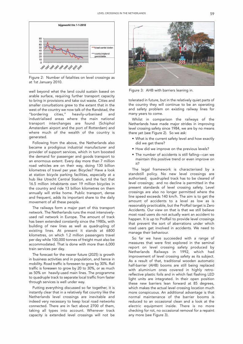
59LEVEL CROSSINGS IN THE NETHERLANDS
tolerated in future, but in the relatively quiet parts ofthe country they will continue to be an operatingand safety problem on existing railway lines formany years to come.
Whilst in comparison the railways of theNetherlands have made major strides in improvinglevel crossing safety since 1984, we are by no meansthere yet (see Figure 2). So we ask:
• What is the current safety level and how exactlydid we get there?
• How did we improve on the previous levels?
• The number of accidents is still falling—can wemaintain this positive trend or even improve onit?
The legal framework is characterised by astandstill policy. No new level crossings areauthorised; quadrupled track has to be cleared oflevel crossings; and no decline is permitted in thepresent standards of level crossing safety. Levelcrossings are also no longer permitted where theline speed exceeds 140 km/h. The aim is to get theamount of accidents to a level as low as isreasonably practicable, but the ProRail target is ZeroAccidents. Our view on that is that we still believemost road users do not actually want an accident tohappen. It is up to ProRail to provide level crossingsthat prevent the sort of aberrations under whichroad users get involved in accidents. We need tomanage their behaviour.
So far we have succeeded with a range ofmeasures that were first explored in the seminalreport on level crossing safety produced byNetherlands Railways in 1992, which hadimprovement of level crossing safety as its subject.As a result of that, traditional wooden automatichalf-barrier (AHB) booms are still being replacedwith aluminium ones covered in highly retro-reflective plastic foils and in which fast flashing LEDlight units are integrated. In their open positionthese new barriers lean forward at 85 degrees,which makes the actual level crossing location muchmore conspicuous. An additional advantage is thatnormal maintenance of the barrier booms isreduced to an occasional clean and a look at theelectric equipment inside. There is no morechecking for rot, no occasional removal for a repaintany more (see Figure 3).
Figure 2: Number of fatalities on level crossings asat 1st January 2010.
well beyond what the land could sustain based onarable surface, requiring further transport capacityto bring in provisions and take out waste. Cities andsmaller conurbations grew to the extent that in thewest of the country we now talk of the Randstad, the“bordering cities,” heavily-urbanised andindustrialised areas where the main nationaltransport interchanges are found (SchipholAmsterdam airport and the port of Rotterdam) andwhere much of the wealth of the country isgenerated.
Following from the above, the Netherlands alsobecame a prodigious industrial manufacturer andprovider of support services, which in turn boostedthe demand for passenger and goods transport toan enormous extent. Every day more than 7 millionroad vehicles are on their way, doing 130 billionkilometres of travel per year. Bicycles? Have a lookat station bicycle parking facilities, especially at ahub like Utrecht Central Station, and the fact that16.5 million inhabitants own 19 million bicycles inthe country and ride 13 billion kilometres on themannually will strike home. Public transport, denseand frequent, adds its important share to the dailymovement of all these people.
The railways form a major part of this transportnetwork. The Netherlands runs the most intensively-used rail network in Europe. The amount of trackhas been extended constantly since the 1980s, withbuilding of new lines as well as quadrupling ofexisting lines. At present it stands at 6800kilometres, on which 1.2 million passengers travelper day while 100,000 tonnes of freight must also beaccommodated. That is done with more than 6,000train services per day.
The forecast for the nearer future (2025) is growthin business activities and in population, and hence inmobility. Road traffic is foreseen to grow by 30%. Railtraffic is foreseen to grow by 20 to 30%, or as muchas 50% on heavily-used main lines. The programmeto quadruple track to separate local traffic from fasterthrough services is well under way.
Putting everything discussed so far together, it isinstantly clear that in a relatively flat country like theNetherlands level crossings are inevitable andindeed very necessary to keep local road networksconnected. There are in fact about 2700 of them,taking all types into account. Wherever trackcapacity is extended level crossings will not be
Figure 3: AHB with barriers leaning in.
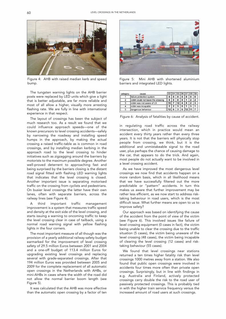
60 LEVEL CROSSINGS IN THE NETHERLANDS
The tungsten warning lights on the AHB barrierposts were replaced by LED units which give a lightthat is better adjustable, are far more reliable andmost of all allow a higher, visually more arrestingflashing rate. We are fully in line with internationalexperience in that respect.
The layout of crossings has been the subject ofmuch research too. As a result we found that wecould influence approach speeds—one of theknown precursors to level crossing accidents—safelyby narrowing the roadway and installing speedhumps in the approach, by making the actualcrossing a raised traffic-table as is common in roadcrossings, and by installing median kerbing in theapproach road to the level crossing to hinderinitiatives such as zigzagging around the barriers bymotorists to the maximum possible degree. Anotherwell-proved deterrent to approaching fast andbeing surprised by the barriers closing is the distantroad signal fitted with flashing LED warning lightsthat indicates that the level crossing is closed.Another important issue is separating motorisedtraffic on the crossing from cyclists and pedestrians.On busier level crossings the latter have their ownlanes, often with separate barriers, across therailway lines (see Figure 4).
A third important traffic managementimprovement is a system that measures traffic speedand density at the exit side of the level crossing, andstarts issuing a warning to oncoming traffic to keepthe level crossing clear in case of tailback, using anormal road warning signal with yellow flashinglights in the four corners.
The most important measure of all though was theprovision of a yearly additional railway safety budgetearmarked for the improvement of level crossingsafety of 29.5 million Euros between 2001 and 2004and a one-off budget of 113.4 million Euros forupgrading existing level crossings and replacingseveral with grade-separated crossings. After that194 million Euros was provided between 2005 and2009 for the complete replacement of all automaticopen crossings in the Netherlands with AHBs, ormini-AHBs in cases where the width of the road didnot allow the normal barrier boom length (seeFigure 5).
It was calculated that the AHB was more effectivethan the automatic open crossing by a factor of ten
Figure 4: AHB with raised median kerb and speedbump.
in regulating road traffic across the railwayintersection, which in practice would mean anaccident every thirty years rather than every threeyears. It is not that the barriers will physically stoppeople from crossing, we think, but it is theadditional and unmistakeable signal to the roaduser, plus perhaps the chance of causing damage tothe car, that appears to do the trick. And again,most people do not actually want to be involved ina level crossing accident.
As we have improved the most dangerous levelcrossings we now find that accidents happen on amore random basis, which in all likelihood meansthat we have successfully filtered out the morepredictable or “pattern” accidents. In turn thismakes us aware that further improvement may berather less efficient, as we now start to address risk-taking behaviour in road users, which is the mostdifficult issue. What further means are open to us toimprove safety?
Our approach was based on identifying the causeof the accident from the point of view of the victim(see Figure 6). This involved issues like failure oflevel crossing equipment (0 cases in fact), the victimbeing unable to clear the crossing due to the trafficsituation (5 cases), the victim being unaware of thelevel crossing (48 cases), the victim being incapableof clearing the level crossing (12 cases) and risk-taking behaviour (55 cases).
We found that level crossings near stationsreturned a ten times higher fatality risk than levelcrossings 1000 metres away from a station. We alsofound that public open crossings were involved inaccidents four times more often than private opencrossings. Surprisingly, but in line with findings ine.g. Australia and Finland, actively protectedcrossings carry double the risk to the road user ofpassively protected crossings. This is probably tiedin with the higher train service frequency versus theincreased amount of road users at such crossings.
Figure 5: Mini AHB with shortened aluminiumbarriers and integrated LED lights.
Figure 6: Analysis of fatalities by cause of accident.
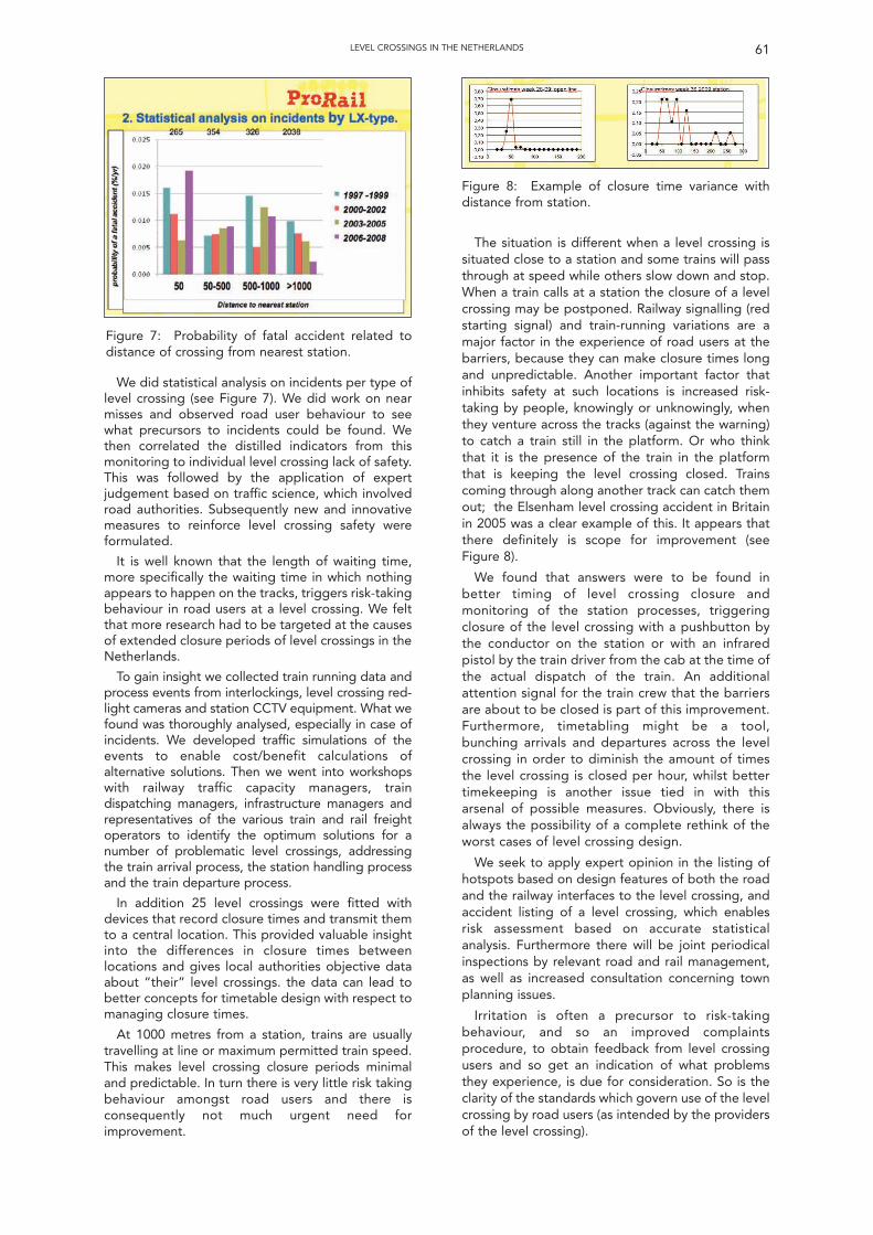
61LEVEL CROSSINGS IN THE NETHERLANDS
We did statistical analysis on incidents per type oflevel crossing (see Figure 7). We did work on nearmisses and observed road user behaviour to seewhat precursors to incidents could be found. Wethen correlated the distilled indicators from thismonitoring to individual level crossing lack of safety.This was followed by the application of expertjudgement based on traffic science, which involvedroad authorities. Subsequently new and innovativemeasures to reinforce level crossing safety wereformulated.
It is well known that the length of waiting time,more specifically the waiting time in which nothingappears to happen on the tracks, triggers risk-takingbehaviour in road users at a level crossing. We feltthat more research had to be targeted at the causesof extended closure periods of level crossings in theNetherlands.
To gain insight we collected train running data andprocess events from interlockings, level crossing red-light cameras and station CCTV equipment. What wefound was thoroughly analysed, especially in case ofincidents. We developed traffic simulations of theevents to enable cost/benefit calculations ofalternative solutions. Then we went into workshopswith railway traffic capacity managers, traindispatching managers, infrastructure managers andrepresentatives of the various train and rail freightoperators to identify the optimum solutions for anumber of problematic level crossings, addressingthe train arrival process, the station handling processand the train departure process.
In addition 25 level crossings were fitted withdevices that record closure times and transmit themto a central location. This provided valuable insightinto the differences in closure times betweenlocations and gives local authorities objective dataabout “their” level crossings. the data can lead tobetter concepts for timetable design with respect tomanaging closure times.
At 1000 metres from a station, trains are usuallytravelling at line or maximum permitted train speed.This makes level crossing closure periods minimaland predictable. In turn there is very little risk takingbehaviour amongst road users and there isconsequently not much urgent need forimprovement.
Figure 7: Probability of fatal accident related todistance of crossing from nearest station.
Figure 8: Example of closure time variance withdistance from station.
The situation is different when a level crossing issituated close to a station and some trains will passthrough at speed while others slow down and stop.When a train calls at a station the closure of a levelcrossing may be postponed. Railway signalling (redstarting signal) and train-running variations are amajor factor in the experience of road users at thebarriers, because they can make closure times longand unpredictable. Another important factor thatinhibits safety at such locations is increased risk-taking by people, knowingly or unknowingly, whenthey venture across the tracks (against the warning)to catch a train still in the platform. Or who thinkthat it is the presence of the train in the platformthat is keeping the level crossing closed. Trainscoming through along another track can catch themout; the Elsenham level crossing accident in Britainin 2005 was a clear example of this. It appears thatthere definitely is scope for improvement (seeFigure 8).
We found that answers were to be found inbetter timing of level crossing closure andmonitoring of the station processes, triggeringclosure of the level crossing with a pushbutton bythe conductor on the station or with an infraredpistol by the train driver from the cab at the time ofthe actual dispatch of the train. An additionalattention signal for the train crew that the barriersare about to be closed is part of this improvement.Furthermore, timetabling might be a tool,bunching arrivals and departures across the levelcrossing in order to diminish the amount of timesthe level crossing is closed per hour, whilst bettertimekeeping is another issue tied in with thisarsenal of possible measures. Obviously, there isalways the possibility of a complete rethink of theworst cases of level crossing design.
We seek to apply expert opinion in the listing ofhotspots based on design features of both the roadand the railway interfaces to the level crossing, andaccident listing of a level crossing, which enablesrisk assessment based on accurate statisticalanalysis. Furthermore there will be joint periodicalinspections by relevant road and rail management,as well as increased consultation concerning townplanning issues.
Irritation is often a precursor to risk-takingbehaviour, and so an improved complaintsprocedure, to obtain feedback from level crossingusers and so get an indication of what problemsthey experience, is due for consideration. So is theclarity of the standards which govern use of the levelcrossing by road users (as intended by the providersof the level crossing).
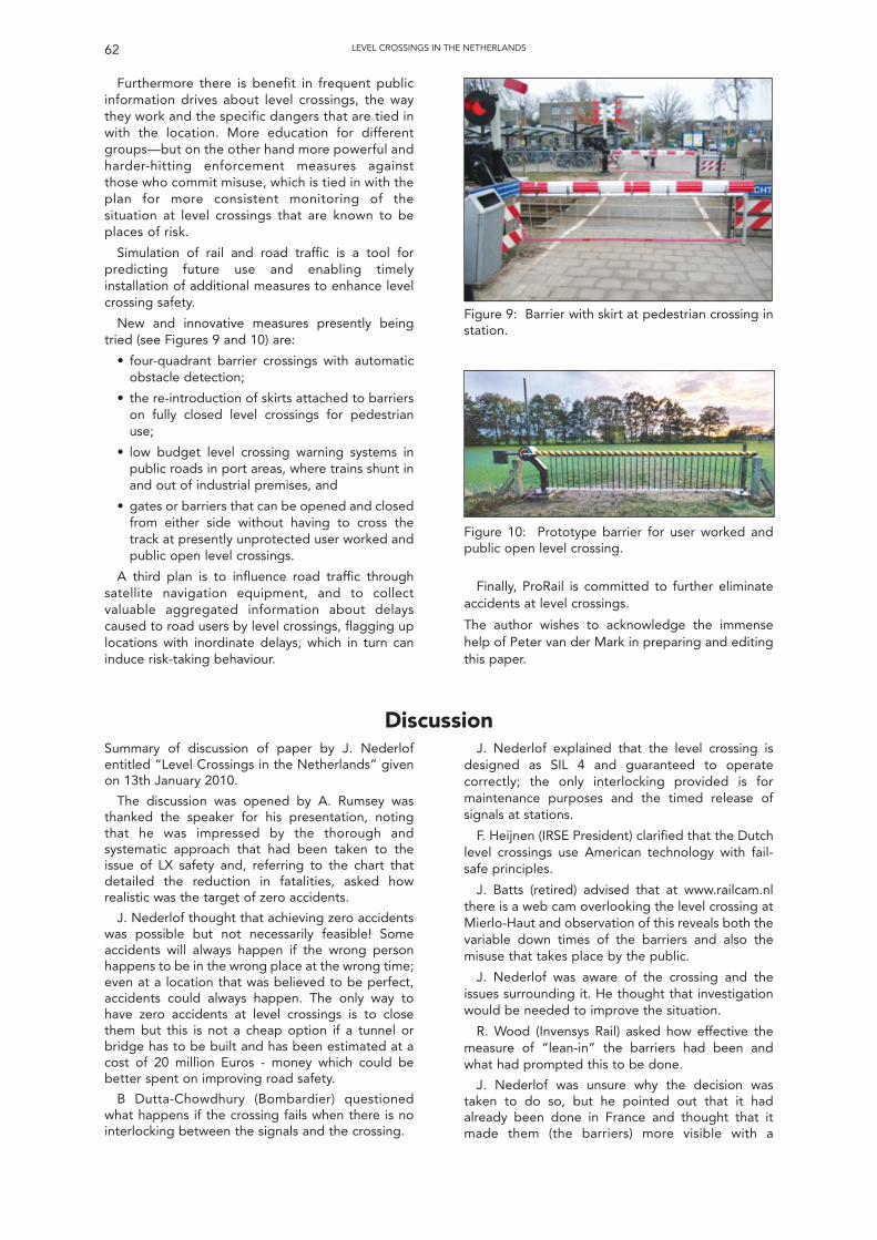
Furthermore there is benefit in frequent publicinformation drives about level crossings, the waythey work and the specific dangers that are tied inwith the location. More education for differentgroups—but on the other hand more powerful andharder-hitting enforcement measures againstthose who commit misuse, which is tied in with theplan for more consistent monitoring of thesituation at level crossings that are known to beplaces of risk.
Simulation of rail and road traffic is a tool forpredicting future use and enabling timelyinstallation of additional measures to enhance levelcrossing safety.
New and innovative measures presently beingtried (see Figures 9 and 10) are:
• four-quadrant barrier crossings with automaticobstacle detection;
• the re-introduction of skirts attached to barrierson fully closed level crossings for pedestrianuse;
• low budget level crossing warning systems inpublic roads in port areas, where trains shunt inand out of industrial premises, and
• gates or barriers that can be opened and closedfrom either side without having to cross thetrack at presently unprotected user worked andpublic open level crossings.
A third plan is to influence road traffic throughsatellite navigation equipment, and to collectvaluable aggregated information about delayscaused to road users by level crossings, flagging uplocations with inordinate delays, which in turn caninduce risk-taking behaviour.
Finally, ProRail is committed to further eliminateaccidents at level crossings.
The author wishes to acknowledge the immensehelp of Peter van der Mark in preparing and editingthis paper.
LEVEL CROSSINGS IN THE NETHERLANDS62
Figure 9: Barrier with skirt at pedestrian crossing instation.
Figure 10: Prototype barrier for user worked andpublic open level crossing.
DiscussionSummary of discussion of paper by J. Nederlofentitled “Level Crossings in the Netherlands” givenon 13th January 2010.
The discussion was opened by A. Rumsey wasthanked the speaker for his presentation, notingthat he was impressed by the thorough andsystematic approach that had been taken to theissue of LX safety and, referring to the chart thatdetailed the reduction in fatalities, asked howrealistic was the target of zero accidents.
J. Nederlof thought that achieving zero accidentswas possible but not necessarily feasible! Someaccidents will always happen if the wrong personhappens to be in the wrong place at the wrong time;even at a location that was believed to be perfect,accidents could always happen. The only way tohave zero accidents at level crossings is to closethem but this is not a cheap option if a tunnel orbridge has to be built and has been estimated at acost of 20 million Euros - money which could bebetter spent on improving road safety.
B Dutta-Chowdhury (Bombardier) questionedwhat happens if the crossing fails when there is nointerlocking between the signals and the crossing.
J. Nederlof explained that the level crossing isdesigned as SIL 4 and guaranteed to operatecorrectly; the only interlocking provided is formaintenance purposes and the timed release ofsignals at stations.
F. Heijnen (IRSE President) clarified that the Dutchlevel crossings use American technology with fail-safe principles.
J. Batts (retired) advised that at www.railcam.nlthere is a web cam overlooking the level crossing atMierlo-Haut and observation of this reveals both thevariable down times of the barriers and also themisuse that takes place by the public.
J. Nederlof was aware of the crossing and theissues surrounding it. He thought that investigationwould be needed to improve the situation.
R. Wood (Invensys Rail) asked how effective themeasure of “lean-in” the barriers had been andwhat had prompted this to be done.
J. Nederlof was unsure why the decision wastaken to do so, but he pointed out that it hadalready been done in France and thought that itmade them (the barriers) more visible with a
63
psychological factor making people believe that thebarriers were already descending.
F. Heijnen (IRSE President) clarified that thistechnique was also applied in the US.
A. Kornas (Invensys Rail) was interested to knowwhat results had been seen from the efforts toeducate pedestrians and road users.
J. Nederlof explained that they were unsure of theeffectiveness of the education but it is somethingthat other countries and whilst it is difficult toquantify the results, it is something that they willcontinue to do as they believe it helps.
P. Van de Mark (First Great Western) thought thatpeople will do things based on what they believe isthe case and that education is therefore essential toimprove the safety at level crossings. He alsoexplained that in Holland, if a level crossing isdetected as having failed, the driver is advised toproceed at caution and the barriers will (only) thendrop when the train occupies the track circuit overthe level crossing.
I. Harman (Network Rail) was interested in anyrules that were applied to the cycle time of the levelcrossing and how they were enforced.
J. Nederlof explained that there were engineeringrules which enable calculation of when the levelcrossing should be initiated based on various factorsincluding line speed and road user transit time; thereare no laws for the maximum or minimum roadclosure times but road closure times were optimised.
D. Fenner (Network Rail) thought that statistics inthe UK showed that there were increases in peopleattempting to commit suicide on level crossings andthat more incidents occurred at certain times of theyear, such as in the autumn and spring as a result oflow sunlight, and he wondered if this had been alsobeen seen in the Netherlands.
J. Nederlof advised that suicides on level crossingswere not considered as a level crossing accident.Their analysis had also not shown that there were anyspecific seasonal issues resulting in an increase inaccidents even when all factors had been considered.
W. Coenraad (Movares) commented that therewere sunlight issues some years ago but these hadbeen addressed and are not now deemed to be aproblem.
J. Nederlof also pointed out that the flashing rateof the crossing lights was increased and there arealso now a lot more crossings that have been fittedwith barriers.
D. McKeown (Institute of Asset Management)asked for some idea of the costs involved andwondered if the case had now been made for notdoing anything else; spending the moneyelsewhere. He also questioned if the signal engineershould consider the road-user and concentrate oncrossing open times?
J. Nederlof explained the programme has so farcost several hundred million Euros, which equates toabout 23 million Euros per yearly saved life. ProRailbelieve that the Minister will request a continuationin the programme of improvements but are unsureof how far they should go. He thought that opentimes should also be considered such that a decision
can be made as to whether or not a crossing is keptclosed if there is only going to be a short period ofopen time; generally it has been considered betterto open the crossing even if it only allows a few carsto cross.
S. Eastmond (Network Rail) asked if there wereproblems in fitting half barriers to open crossings onminor roads, where restricted widths could preventvehicles from escaping.
J. Nederlof explained that these crossings werefitted with smaller barriers where required.
C. Porter (IRSE) observed that the protectionsystems were often based on standard Americanpractice and technologies and asked ifconsideration had been given to the use of ConstantWarning Time Crossings.
J. Nederlof explained that they had beenconsidered but was not sure if they would work withthe Dutch fail-safe crossing concept, short approachtimes and the proximity of stations, however, forcrossings in open territory with differingcharacteristics between freight and passengertrains, there could be some benefits.
F. Heijnen (IRSE President) also added that theConstant Warning Time and Predictor Crossingsoften utilise overlay track circuits which can beadversely affected when block joints and impedancebonds are provided for traction return purposes.
J. Nederlof thought that perhaps themanufacturers of the predictor equipment could bechallenged to come up with a solution.
C. Hall (RAIB) noted that the most successfulmeasure had been the fitting of barriers to opencrossings and asked where the justification toundertake this work had come.
J. Nederlof was unsure how the finance wasdecided but the programme was funded by theGovernment.
F. Heijnen (IRSE President) clarified that inHolland, there was no requirement to undertake acost/benefit analysis for each level crossing but aprogramme of work was drawn up and costed whichwas then funded.
J. Nederlof explained that the Dutch philosophywas that with such a large programme ofimprovements there were bound to be overallbenefits from doing the work.
J. Hinchcliffe (Signalling Solutions) believed thatNetwork Rail had commissioned its first obstacledetection system and asked where they were fittedand how reliable they have been.
J. Nederlof explained that there were threeinstallations in work at the present time, the initialinstallations about two to three years ago. Someproblems had been experienced with theequipment and failure of the system result in the exitbarriers remaining open with the crossing behavinglike an half barrier crossing, however, this has causedproblems with the road users and ProRail were nowlooking to review the whole concept.
F. Heijnen (IRSE President) thanked the author forhis interesting paper and the debate that followed.
(Produced by Peter Grant)
LEVEL CROSSINGS IN THE NETHERLANDS
64
Control Systems: Are Rail and Air So Different?Gottfried Allmer1
1 The author is with Frequentis.
Technical Meeting of the Institutionheld at
1 Birdcage Walk, London
Wednesday 10th February 2010
The President, Mr F Heijnen, in the chair.82 members and visitors were in attendance. There were apologies for absence from David Weedon and Ken Burrage. It was proposed by Mr W J Coenraad, seconded by Mr D
McKeown and carried that the minutes of the technical meeting held on 13 January 2010 be taken as read and they were signed byMr Heijnen as a correct record.
The Chairman invited any new members present for the first time since their election to come forward to be introduced to themeeting, and a new member from Atkins came forward to be introduced to warm applause.The Chairman then introduced Gottfried Allmer (Frequentis, Austria) and asked him to present his paper “Control Systems - Are Railand Air so Different?”
Mr Allmer started his presentation by showing some photographs of surprisingly similar looking control rooms for some modern railand air traffic installations. He used the analogy of the transit of an aircraft from air sector to air sector during a journey as a sort oflevel 3 moving block system for air. He explained some key differences between signalling control and air traffic control, but also somesimilarities. He postulated that it was more straightforward to gain acceptance for new systems if the method of working replicatedthe manual processes previously used wherever practicable in order to maintain familiarity with the process between new and oldtechnology. He finished by showing a schematic of an air traffic control system and described the process used for live updates to thesoftware.
Following the presentation, the discussion was opened by Paul Jenkins, (Vice-President). Jon Shaw (Ansaldo STS), John Francis(Network Rail), John Gurney (Frequentis), Clive Kessell (Past-President), Peter van der Mark (First Great Western), Ian Mitchell(DeltaRail) and Wim Coenraad (Past-President and Movares) all took part in the discussion.
The Chairman then thanked the speaker and proposed a vote of thanks to him for his very interesting presentation which hadshowed some interesting contrasts as well as similarities between the two modes of transport. He then presented him with acommemorative plaque customarily awarded to the author of a London paper, to warm applause from the audience.
Mr Heijnen thanked members and visitors for their attendance and their contribution, and then in closing the meeting at 19.30,stated that the next meeting in London would be a technical meeting held on the 10 March 2010 when Mr Anshul Gupta, from RailtelIndia would present a paper on Signalling and telecommunications in India as a precursor to the convention to be held in Delhi inOctober 2010.
meet similar patterns of problem at some point. Butit does get more telling if we look into the detail ofhow institutions deal with these challenges, and howsystems are really set up. This is what this paperintends to do, for perhaps there is some commonground between control centres of differenttransportation genres which is not really discussed.
HOW DO RAIL AND AIR COMPARE?This paper will in no way suggest that anything
could or should be copied from one field oftransport to the other. And by absolutely no meansdoes Rail have to look up to Air to learn how to dothings correctly. Indeed there are areas where theopposite is the case. Take the drive to Internetprotocol (IP) networks. I for one would expect Railinstitutions to change more quickly to IP backbonesthan their air traffic counterparts (the non-militaryones at least), simply because the scale is larger inthe case of Rail so that the business case is stronger.
One thing Air does seem to have though is morebudget – not in total, but that part of the budgetthat systems architects can use “to play aroundwith.” This is not surprising given that Air does nothave to build and maintain the track for its vehicles.
INTRODUCTION“The European airspace is fragmented and will
become more and more congested, as traffic isforecast to grow steadily over the next 15 years. Theair navigation services and their supporting systemsare not fully integrated and are based ontechnologies which are already running atmaximum. In order to accommodate future air trafficneeds a “paradigm shift”, supported by state-of-the-art and innovative technologies, is required.”
Does that sound remotely familiar? It is theintroductory statement in EUROCONTROL’s SESARprogramme, which is a vision to create a seamlessregion of areas of responsibility for air traffic controlover the whole of Europe. The first three letters SESstand for “Single European Sky.”
Now substitute railway for airspace, signallingsystems for air navigation services and rail traffic forair traffic—and we have a statement which is equallytrue for rail.
This may not be entirely surprising. Withincreasing size, all transport systems will probably
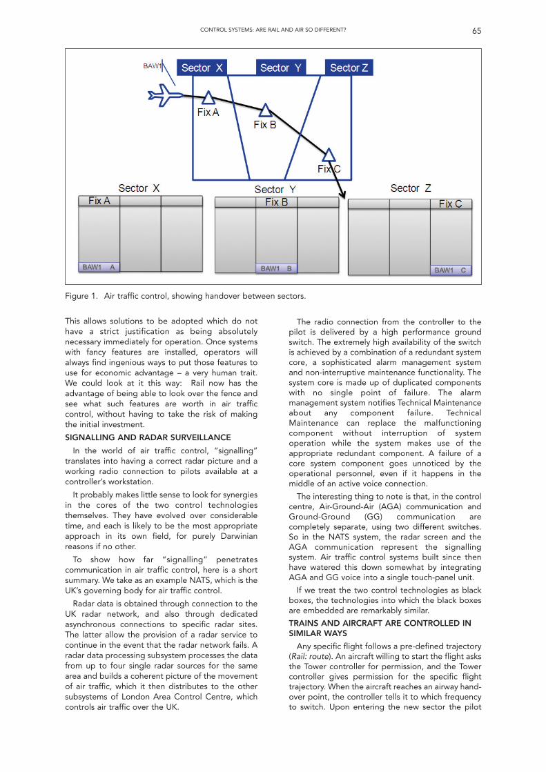
CONTROL SYSTEMS: ARE RAIL AND AIR SO DIFFERENT? 65
This allows solutions to be adopted which do nothave a strict justification as being absolutelynecessary immediately for operation. Once systemswith fancy features are installed, operators willalways find ingenious ways to put those features touse for economic advantage – a very human trait.We could look at it this way: Rail now has theadvantage of being able to look over the fence andsee what such features are worth in air trafficcontrol, without having to take the risk of makingthe initial investment.
SIGNALLING AND RADAR SURVEILLANCE
In the world of air traffic control, “signalling”translates into having a correct radar picture and aworking radio connection to pilots available at acontroller’s workstation.
It probably makes little sense to look for synergiesin the cores of the two control technologiesthemselves. They have evolved over considerabletime, and each is likely to be the most appropriateapproach in its own field, for purely Darwinianreasons if no other.
To show how far “signalling” penetratescommunication in air traffic control, here is a shortsummary. We take as an example NATS, which is theUK’s governing body for air traffic control.
Radar data is obtained through connection to theUK radar network, and also through dedicatedasynchronous connections to specific radar sites.The latter allow the provision of a radar service tocontinue in the event that the radar network fails. Aradar data processing subsystem processes the datafrom up to four single radar sources for the samearea and builds a coherent picture of the movementof air traffic, which it then distributes to the othersubsystems of London Area Control Centre, whichcontrols air traffic over the UK.
The radio connection from the controller to thepilot is delivered by a high performance groundswitch. The extremely high availability of the switchis achieved by a combination of a redundant systemcore, a sophisticated alarm management systemand non-interruptive maintenance functionality. Thesystem core is made up of duplicated componentswith no single point of failure. The alarmmanagement system notifies Technical Maintenanceabout any component failure. TechnicalMaintenance can replace the malfunctioningcomponent without interruption of systemoperation while the system makes use of theappropriate redundant component. A failure of acore system component goes unnoticed by theoperational personnel, even if it happens in themiddle of an active voice connection.
The interesting thing to note is that, in the controlcentre, Air-Ground-Air (AGA) communication andGround-Ground (GG) communication arecompletely separate, using two different switches.So in the NATS system, the radar screen and theAGA communication represent the signallingsystem. Air traffic control systems built since thenhave watered this down somewhat by integratingAGA and GG voice into a single touch-panel unit.
If we treat the two control technologies as blackboxes, the technologies into which the black boxesare embedded are remarkably similar.
TRAINS AND AIRCRAFT ARE CONTROLLED INSIMILAR WAYS
Any specific flight follows a pre-defined trajectory(Rail: route). An aircraft willing to start the flight asksthe Tower controller for permission, and the Towercontroller gives permission for the specific flighttrajectory. When the aircraft reaches an airway hand-over point, the controller tells it to which frequencyto switch. Upon entering the new sector the pilot
Figure 1. Air traffic control, showing handover between sectors.
contacts the new controller. The controller identifiesthe plane unambiguously with the help of its radiobeacon, and then follows the plane on the radarscreen to the next hand-over point.
The presence of the plane is representedphysically by a flight strip on the controller’s desk(see Figure 1, BAW1 A, BAW1 B and BAW1 C).These strips used to be real print-outs, but they arereplaced more and more by an electronicrepresentation on a controller’s screen. This iscurrently less sophisticated than what train radiodelivers, for in Cab Secure Radio and GSM-R thefrequency switching is automated.
JOURNEY DATA IS DISTRIBUTED IN A SIMILARWAY
Flights are coordinated by means of flight plans,electronically stored in a central database for thewhole of Europe, the Central Flight ManagementUnit or CFMU which is located in Maastricht in theNetherlands, the busiest flying region in Europe.Repetitive-flight plans (Rail: timetable) are generatedhalf a year in advance by the airlines and submittedto the CFMU, which distributes the data to thevarious countries’ flight data processing systems.
The flight plan is entered into the air traffic controlflight data processing system automatically, all thedatabases sitting in an IP cloud which it owns. Thecontrollers access all their data from the flight dataprocessing system to route the planes through thetrajectories. The flight plan is normally not changed.In case of small abnormalities, the controllersimprovise a modified route up to the next hand-overpoint. Only in case of major traffic disruption is thedata in the flight data processing system changed—in that case by the controller locally and not via theCFMU.
CONGESTION HANDLING
If there is congestion along the way this isreported to CFMU, which recalculates the globalflight plan and distributes the updated version tothe flight data processing systems. The Towercontroller does not give start permission to theplane and it is held on the ground until CFMU hasworked out a slot, an extra-normal trajectory to theplane’s destination.
Network Rail currently has a tender out to renewthe whole of traffic management, so Rail is going tofollow a similar path in the immediate future.
COST ISSUES SHOW UP IN SIMILAR WAYS
In both Rail and Air there is potential for costsavings by “removing” country borders.
Rail hopes to eliminate border crossing costsusing ERTMS.
In the case of Air, although flight routes arealready managed centrally in EUROCONTROL’sCFMU, fragmentation of the European airspace stillcauses higher costs than necessary. This is becauseairspace always has borders running along countryborders, and because most countries in Europe onlyhave narrow airways for civil aviation cutting throughimmense, largely-unused areas reserved for themilitary.
66 CONTROL SYSTEMS: ARE RAIL AND AIR SO DIFFERENT?
VISIONS OF THE FUTURERail is pushing for ERTMS, a Europe-wide
harmonised train control and communicationsystem, with ETCS for train control and GSM-R theradio system to handle communications, bothcontrol and voice. Regarding geographicalorganization of systems, we have a trend towardspulling control sites out of the countryside into a farsmaller number of larger control centres.
Air avoids some of the standardisation problemsthat the Rail community faces naturally becausemost of the traffic has always been international, butit has congestion problems and it has to cut theoperating costs of control.
Air Traffic Control in Europe is currently in theprocess of creating the “Single European Sky”(SESAR). This is an ambitious programme foundedby EUROCONTROL and the European Commission.EUROCONTROL is the Brussels-based Air TrafficManagement agency with practically all theEuropean states as members. SESAR aims to mergecurrent airspace areas of responsibility into biggerblocks in order to be more flexible in thetrajectories. Flight paths should be disentangled torequire less involvement by controllers along theroute (cutting down on the number of controllersrequired), and should follow more direct routes forfuel efficiency. This programme was started asrecently as 2008.
So again, there is the similarity that Europe-wideprogrammes of harmonization are in place (andeven have similar timescales). However, while Rail isstill struggling more in the control area, Air isalready more involved in the specifics of trafficmanagement.
AREAS OF TECHNOLOGICAL ADVANCESo where are the differences? Currently we are
seeing technical improvements in the followingareas. No claim is made for completeness.
SINGLE CONTROLLER’S WORKSTATION
First there is the quest for prediction functionality,to permit conflicts between trains or aircraft to beseen as they emerge. Rail would seem to be in fronthere with the time-distance diagram, although itonly shows the traffic on two tracks at a time.
Air traffic control centres are currently developingtools which allow prediction for the whole area ofresponsibility. In the United Kingdom the air trafficcontrol institution NATS is currently rolling out aproduct named iFACTS which allows controllers tosee up to 18 minutes ahead. The motive is to be ableto control higher aircraft density without the need ofairspace redesign (in effect achieving the ambitionsof SESAR with technology on the single workstation).
However while this is being developed in a controlcontext, it will quite probably be used even moreextensively in a traffic management context. Routecontrollers will test the viability of various options,and choose the most economical.
A track diagram where you can make artificialdecisions and then “fast forward” into the future tosee the situation unfold in the controlled area would
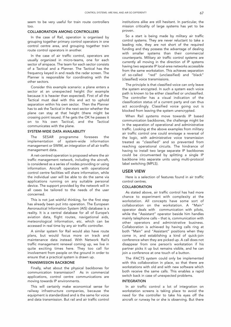
seem to be very useful for train route controllerstoo.
COLLABORATION AMONG CONTROLLERS
In the case of Rail, operation is organised bygrouping together primary control operators in onecontrol centre area, and grouping together trainroute control operators in another.
In the case of air traffic control, operators areusually organized in micro-teams, one for eachsector of airspace. The team for each sector consistsof a Tactical and a Planner. The Tactical has thefrequency keyed in and reads the radar screen. ThePlanner is responsible for coordinating with theother sectors.
Consider this example scenario: a plane enters asector at an unexpected height (for examplebecause it is heavier than expected). First of all theTactical must deal with this and act to upholdseparation within his own sector. Then the Plannerhas to ask the Tactical in the next sector whether theplane can stay at that height (there might becrossing point issues). If he gets the OK he passes iton to his own Tactical, and the Tacticalcommunicates with the plane.
SYSTEM-WIDE DATA AVAILABILITY
The SESAR programme foresees theimplementation of system-wide informationmanagement or SWIM, an integration of all air trafficmanagement data.
A net-centred operation is proposed where the airtraffic management network, including the aircraft,is considered as a series of nodes providing or usinginformation. Aircraft operators with operationalcontrol centre facilities will share information, whilethe individual user will be able to do the same viaapplications running on any suitable personaldevice. The support provided by the network will inall cases be tailored to the needs of the userconcerned.
This is not just wishful thinking, for the first stephas already been put into operation. The EuropeanAeronautical Information System (AIS) database is areality. It is a central database for all of Europe’saviation data, flight routes, navigational aids,meteorological information, etc. which can beaccessed in real time by any air traffic controller.
A similar system for Rail would also have routeplans, but would focus more on track andmaintenance data instead. With Network Rail’straffic management renewal coming up, we live inquite exciting times here. They too call forinvolvement from people on the ground in order toensure that a practical system is drawn up.
TRANSMISSION BACKBONE
Finally, what about the physical backbones forcommunication transmission? As in commercialapplications, control centre communications aremoving towards IP environments.
This will certainly make economical sense forrailway infrastructure companies, because theequipment is standardized and is the same for voiceand data transmission. But rail and air traffic control
institutions alike are still hesitant. In particular, themission criticality of large systems has yet to beproven.
So a start is being made by military air trafficcontrol systems. They are never reluctant to take aleading role, they are not short of the requiredfunding and they possess the advantage of dealingwith smaller systems than their commercialcounterparts. Military air traffic control systems arecurrently all moving in the direction of IP systemshaving two separate IP local-area networks accessiblefrom the same workstation. This achieves separationof so-called “red” (unclassified) and “black”(classified) voice transmissions.
The principle is that classified voice can only leavethe system encrypted. In such a system each voicepath is known to be either classified or unclassified.The controller has a visual indication of theclassification status of a current party and can thusact accordingly. Classified voice going out isblocked from leaving the system unencrypted.
When Rail systems move towards IP basedcommunication backbones, the challenge might bein the separation of operational and administrativetraffic. Looking at the above examples from militaryair traffic control one could envisage a reversal ofthe logic, with administrative voice transmissiontreated as “classified” and so prevented fromreaching operational circuits. The hindrance ofhaving to install two large separate IP backbonescould be circumvented by splitting a single IPbackbone into separate units using multi-protocollabel switching (MPLS).
USER VIEWHere is a selection of features found in air traffic
control centres.
COLLABORATION
As stated above, air traffic control has had morechance to experiment with complexity at theworkstation. All concepts have some sort ofcollaboration on the workstation. A “Main”operator deals with communication with pilots,while the “Assistant” operator beside him handlesmainly telephone calls – that is, communication withother operators and administrative business.Collaboration is achieved by having calls ring atboth “Main” and “Assistant” positions when theycome in, and establishing a kind of quick-joinconference when they are picked up. A call does notdisappear from one person’s workstation if hispartner picks it up but remains visible, and he canjoin a conference at one touch of a button.
The iFACTS system could only be implementedwith this collaboration in place, so that there areworkstations with old and with new software whichboth receive the same calls. This enables a rapidswitch back in case of unexpected problems.
INTEGRATION
In air traffic control a lot of integration onworkstation screens is taking place to avoid theneed for the controller to take his eyes off theaircraft or runway he or she is observing. But there
67CONTROL SYSTEMS: ARE RAIL AND AIR SO DIFFERENT?
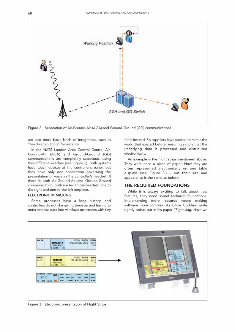
are also more basic kinds of integration, such as“head-set splitting” for instance.
In the NATS London Area Control Centre, Air-Ground-Air (AGA) and Ground-Ground (GG)communications are completely separated, usingtwo different switches (see Figure 2). Both systemshave touch devices at the controller’s panel, butthey have only one connection governing thepresentation of voice in the controller’s headset. Ifthere is both Air-Ground-Air and Ground-Groundcommunication, both are fed to the headset, one tothe right and one to the left earpiece.
ELECTRONIC MIMICKING
Some processes have a long history, andcontrollers do not like giving them up and having toenter endless data into windows on screens with tiny
68 CONTROL SYSTEMS: ARE RAIL AND AIR SO DIFFERENT?
Figure 2. Separation of Air-Ground-Air (AGA) and Ground-Ground (GG) communications.
fonts instead. So suppliers have started to mimic theworld that existed before, ensuring simply that theunderlying data is processed and distributedelectronically.
An example is the flight strips mentioned above.They were once a piece of paper. Now they areoften represented electronically on pen tabledisplays (see Figure 3.) – but their size andappearance is the same as before!
THE REQUIRED FOUNDATIONSWhile it is always exciting to talk about new
features, they need sound technical foundations.Implementing more features means makingsoftware more complex. As Eddie Goddard quiterightly points out in his paper “Signalling: Have we
Figure 3. Electronic presentation of Flight Strips.
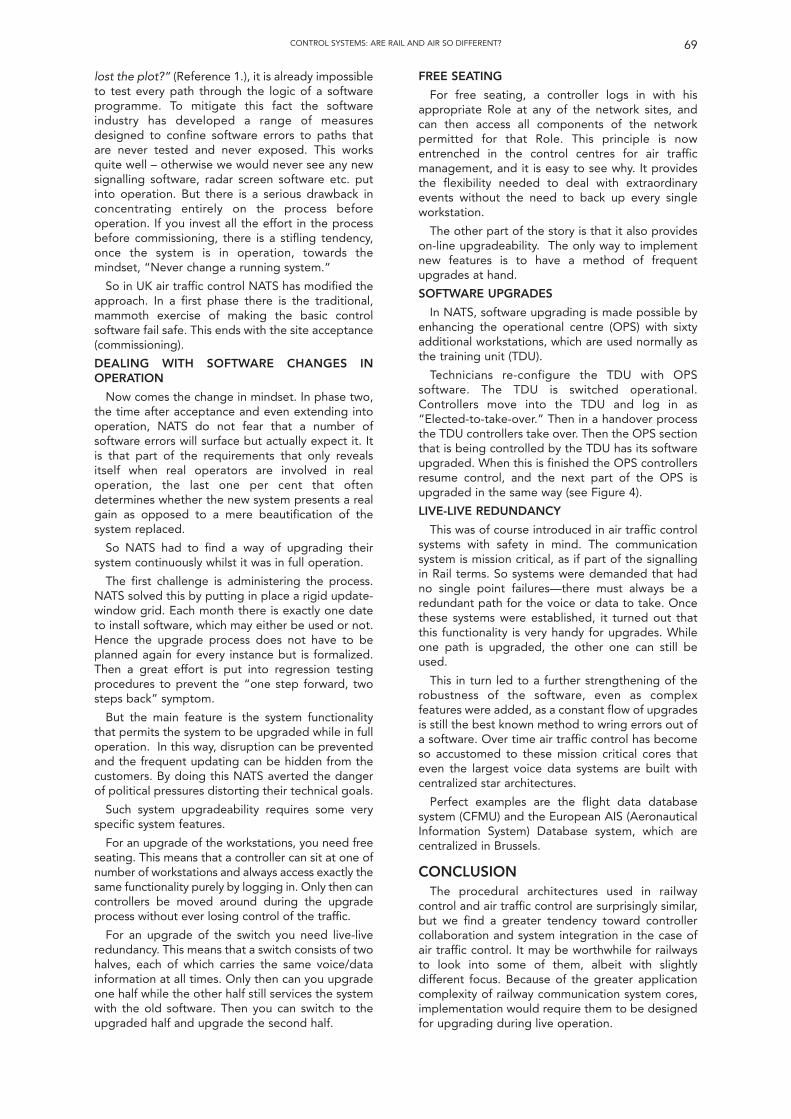
lost the plot?” (Reference 1.), it is already impossibleto test every path through the logic of a softwareprogramme. To mitigate this fact the softwareindustry has developed a range of measuresdesigned to confine software errors to paths thatare never tested and never exposed. This worksquite well – otherwise we would never see any newsignalling software, radar screen software etc. putinto operation. But there is a serious drawback inconcentrating entirely on the process beforeoperation. If you invest all the effort in the processbefore commissioning, there is a stifling tendency,once the system is in operation, towards themindset, “Never change a running system.”
So in UK air traffic control NATS has modified theapproach. In a first phase there is the traditional,mammoth exercise of making the basic controlsoftware fail safe. This ends with the site acceptance(commissioning).
DEALING WITH SOFTWARE CHANGES INOPERATION
Now comes the change in mindset. In phase two,the time after acceptance and even extending intooperation, NATS do not fear that a number ofsoftware errors will surface but actually expect it. Itis that part of the requirements that only revealsitself when real operators are involved in realoperation, the last one per cent that oftendetermines whether the new system presents a realgain as opposed to a mere beautification of thesystem replaced.
So NATS had to find a way of upgrading theirsystem continuously whilst it was in full operation.
The first challenge is administering the process.NATS solved this by putting in place a rigid update-window grid. Each month there is exactly one dateto install software, which may either be used or not.Hence the upgrade process does not have to beplanned again for every instance but is formalized.Then a great effort is put into regression testingprocedures to prevent the “one step forward, twosteps back” symptom.
But the main feature is the system functionalitythat permits the system to be upgraded while in fulloperation. In this way, disruption can be preventedand the frequent updating can be hidden from thecustomers. By doing this NATS averted the dangerof political pressures distorting their technical goals.
Such system upgradeability requires some veryspecific system features.
For an upgrade of the workstations, you need freeseating. This means that a controller can sit at one ofnumber of workstations and always access exactly thesame functionality purely by logging in. Only then cancontrollers be moved around during the upgradeprocess without ever losing control of the traffic.
For an upgrade of the switch you need live-liveredundancy. This means that a switch consists of twohalves, each of which carries the same voice/datainformation at all times. Only then can you upgradeone half while the other half still services the systemwith the old software. Then you can switch to theupgraded half and upgrade the second half.
FREE SEATING
For free seating, a controller logs in with hisappropriate Role at any of the network sites, andcan then access all components of the networkpermitted for that Role. This principle is nowentrenched in the control centres for air trafficmanagement, and it is easy to see why. It providesthe flexibility needed to deal with extraordinaryevents without the need to back up every singleworkstation.
The other part of the story is that it also provideson-line upgradeability. The only way to implementnew features is to have a method of frequentupgrades at hand.
SOFTWARE UPGRADES
In NATS, software upgrading is made possible byenhancing the operational centre (OPS) with sixtyadditional workstations, which are used normally asthe training unit (TDU).
Technicians re-configure the TDU with OPSsoftware. The TDU is switched operational.Controllers move into the TDU and log in as“Elected-to-take-over.” Then in a handover processthe TDU controllers take over. Then the OPS sectionthat is being controlled by the TDU has its softwareupgraded. When this is finished the OPS controllersresume control, and the next part of the OPS isupgraded in the same way (see Figure 4).
LIVE-LIVE REDUNDANCY
This was of course introduced in air traffic controlsystems with safety in mind. The communicationsystem is mission critical, as if part of the signallingin Rail terms. So systems were demanded that hadno single point failures—there must always be aredundant path for the voice or data to take. Oncethese systems were established, it turned out thatthis functionality is very handy for upgrades. Whileone path is upgraded, the other one can still beused.
This in turn led to a further strengthening of therobustness of the software, even as complexfeatures were added, as a constant flow of upgradesis still the best known method to wring errors out ofa software. Over time air traffic control has becomeso accustomed to these mission critical cores thateven the largest voice data systems are built withcentralized star architectures.
Perfect examples are the flight data databasesystem (CFMU) and the European AIS (AeronauticalInformation System) Database system, which arecentralized in Brussels.
CONCLUSIONThe procedural architectures used in railway
control and air traffic control are surprisingly similar,but we find a greater tendency toward controllercollaboration and system integration in the case ofair traffic control. It may be worthwhile for railwaysto look into some of them, albeit with slightlydifferent focus. Because of the greater applicationcomplexity of railway communication system cores,implementation would require them to be designedfor upgrading during live operation.
69CONTROL SYSTEMS: ARE RAIL AND AIR SO DIFFERENT?
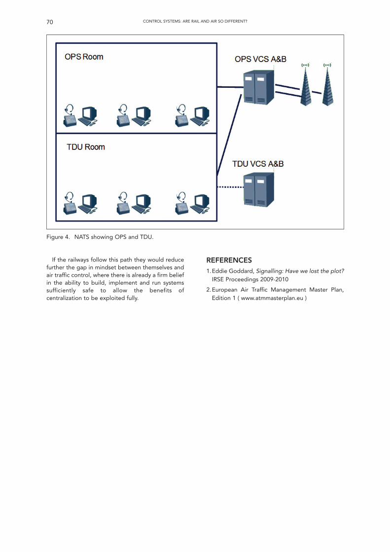
If the railways follow this path they would reducefurther the gap in mindset between themselves andair traffic control, where there is already a firm beliefin the ability to build, implement and run systemssufficiently safe to allow the benefits ofcentralization to be exploited fully.
70 CONTROL SYSTEMS: ARE RAIL AND AIR SO DIFFERENT?
REFERENCES1.Eddie Goddard, Signalling: Have we lost the plot?
IRSE Proceedings 2009-2010
2.European Air Traffic Management Master Plan,Edition 1 ( www.atmmasterplan.eu )
Figure 4. NATS showing OPS and TDU.
Summary of discussion of paper by G. Allmerentitled “Control Systems – Are Rail and Air SoDifferent?” given on 10th February 2010.
The discussion was opened by P. Jenkins (SeniorVice President) who thanked the speaker for hispaper which appeared to describe a three-dimensional form of moving block with no signallingall controlled by voice communication and he askedhow the railway industry could be persuaded toadopt some of the ideas, such as the tactical andstrategic planners working together, used within theAir Traffic Control system.
G. Allmer didn’t think he could persuade anybodyto implement these ideas! He was glad of theopportunity to present what was done in the AirTraffic Control industry, but he didn’t think it wouldbe possible to transfer some of these workingpractices on to the railway. He thought that themethod of putting route controls and collaborationinto place was sensible and implementation ofGSM-R should be the next step to be taken.
J. Shaw (Ansaldo) noted that the speaker hadreferred to the Safety Integrity Level (SIL) of theradio function and asked if there was an associatedSIL for the visual displays.
G. Allmer explained that the “strips” display is ahighly redundant system which was developed witha great deal of security upon it; he was unaware ofthe actual SIL.
J. Francis (Network Rail) observed that the aircraftindustry also had height, as well as space separation,which probably mirrored the “Up” and “Down” lineseparation of the railways although this has beendegraded in more recent years with the introductionof reversible and bi-directional working. He alsonoted that railway communications are movingtowards the provision of in-cab signalling and hewondered if there were any moves to introduce someform of cockpit display that either supplemented orwould replace the voice control. Finally he asked ifthere were any moves toward replacing the analogueradio with digital transmission.
G. Allmer clarified that the voice communicationguarantees aircraft separation; aircraft are also fittedwith a secondary radar system, known as TrafficConflict Avoidance System (TCAS), which advisesthe aircrew if another plane is on a collision coursewith it and can also take avoiding action.
J. Gurney (Frequentis) advised that there were noplans to move ATC communications towards digitaltransmission although Public Safety Systems, suchas TETRA, use a standard digital radio system for“inter-operability” which has additional features thatcould be utilised in a railway environment includingpersonnel and vehicle location.
G. Allmer also explained that there is an Europeaninitiative, within ATC, where the routes aredisentangled to leave only “highways” and this willpotentially lead on to the aircraft flying themselves.In-cockpit information generally only comprisesweather information and there are no plans toreplace the voice communication.
C. Kessell (Retired) noted that the concept ofperforming upgrades and closing down the airspace
is an unheard of concept, as opposed to the railwayswhere disruptive possessions are the norm. Inaddition he asked how approval of the softwarechanges was undertaken and implemented.
G. Allmer confirmed that safety approvals wereundertaken within the industry but he pointed outthat they also go to great lengths to avoidinterfacing with other elements of the system. In theUK, NATS controls this process and any softwaresupplier has to be approved and are audited on anannual basis; the software is not a two-out-of-threetype of software but each line of code has to have aseparate test undertaken which is then audited.
J. Gurney (Frequentis) also clarified that there isan overseeing safety regulatory group, part of theCAA, which sits above NATS.
P. Van der Mark (First Great Western) thought thatthe idea of an in-cab/cockpit display was particularlyrelevant when required to convey some form ofmessage, especially when considering the potentialfor misunderstanding, and he questioned if it waspossible to integrate a display into the cabs of trainsand aircraft flight decks.
G. Allmer believed that there were in-cab displaysfor messages sent using GSM-R with ETCS and headmitted that he, personally, found it very difficult tounderstand the voice communications between ATCand aircraft.
F. Heijnen (IRSE President) also noted that withrailway voice communications, a more formalmethod of communicating was utilised to ensureclarity of speech.
I. Mitchell (Delta Rail) asked how the handoverbetween the different groups of people is managedwhen software changes take place, in particular howspecific information that a person may have in theirmind is transferred.
G. Allmer explained that the “newer, modified”software shouldn’t affect the functionality of thesystem. The oncoming controller “logs-on” andelects to “takeover” control on the upgradedposition, the system having “free-seating”, and theaction of “logging-on” is onto the radar screenworkstation which also has a connection to thetelecommunications element. The individuals cancommunicate with one another if they wish totransfer information.
W. Coenraad (Movares) thought whilst the railwaysystem was probably more complex, IECC type ofcontrol centres could be upgraded using similarfree-seating techniques. For other type of (direct-wired) interlockings this method would not bepossible and he asked for the speaker’s thoughts.He also noted that the railway method of controlwas different from ATC.
G. Allmer believed that the railway method ofroute control was superior to that in ATC. He wasunable to understand why the free-seating methodcouldn’t work even if the infrastructure was hard-wired.
F. Heijnen (IRSE President) thanked the speakerfor his paper, especially coming from both an un-related industry and in a foreign language.
(Produced by Peter Grant)
71CONTROL SYSTEMS: ARE RAIL AND AIR SO DIFFERENT?
Discussion
72
Technical Meeting of the Institutionheld at
1 Birdcage Walk, London
Wednesday 10th March 2010The Senior Vice-President, Mr P Jenkins, in the chair.
64 members and visitors were in attendance. There were apologies for absence from the President who was travelling to the Indian, Singaporean and Australasian Sections and Peter Grant.It was proposed by Mr R W Penny, seconded by Mr C Kessell and carried that the minutes of the technical meeting held on 10 February 2010
be taken as read and they were signed by Mr Jenkins as a correct record. The Chairman invited any new members present for the first time since their election to come forward to be introduced to the meeting, and
Michael Day from Network Rail and D S Paul came forward to be introduced to warm applause.The Chairman then introduced Anshul Gupta (RailTel, India) and asked him to present his paper “Journey for Safe and Reliable Train Control
Systems: Railway Signalling and Telecoms Systems on Indian Railways.”Mr Gupta outlined the history of India, the world’s largest democracy and 4th largest economy with a diverse geography and climate. Public
transport formed a backbone support for the country, from buses through to the Delhi Metro. He described the key parameters of Indian Railwayswith 16 Regions and 67 Divisional offices, 11,000 trains per day and 1.4m employees and annual revenue of US$22bn, and a profit of approxUS$2.5bn. He went on to describe the evolution of signalling in India, with an increasing trend of installing electronic interlockings since 2005. Thefocus of the railway in recent years had been the enhancement of safety, provision of condition monitoring and real time train running informationand the augmentation of line capacity. He then described the system of technical training used for S&T personnel and the development of on boardcontrol systems with TPWS/ETCS level 1 and an anti-collision device. He then described the Railtel fibre-optic based transmission system used tosupport the passenger reservation and GSM-R systems and completed his presentation by describing the success of the Delhi Metro.
Following the presentation, the discussion was opened by Mike Watkins (Consultant). Peter Woodbridge (Invensys), another member, DavidMcKeown (IAM) and Bob Wyatt (consultant) all took part in the discussion.
The Chairman then thanked the speaker and proposed a vote of thanks to him for his very comprehensive presentation which highlighted thesize and complexity of the railways in India and gave a good insight into what members would see during the convention in Delhi in October. Hethen presented him with a commemorative plaque customarily awarded to the author of a London paper, to warm applause from the audience.Mr Jenkins thanked members and visitors for their attendance and their contribution, and then in closing the meeting at 19.55, stated that the nextmeeting in London would be the Annual General Meeting followed by the incoming President’s address on Friday 23 April 2010.
Journey for Safe and Reliable Train ControlSystems: Railway Signalling and Telecomms
Systems on Indian RailwaysAnshul Gupta1
1 The author is Secretary, IRSE Indian Section
INTRODUCTIONINDIA
The Republic of India in South Asia is the seventh-largest country by geographical area in the world,the second-most populous country and the mostpopulous democracy. The Constitution of India, thelongest and most exhaustive constitution of anyindependent nation in the world, came into force on26th January 1950. The preamble of the constitutiondefines India as a sovereign, socialist, secular,democratic republic. India has a bicameralparliament operating under a Westminster-styleparliamentary system. Bounded by the Indian Oceanto the south, the Arabian Sea to the west and theBay of Bengal to the east, India has a coastline of7517 km. Home to the Indus Valley civilisation and aregion of historic trade routes and vast empires, theIndian subcontinent was identified with itscommercial and cultural wealth for much of its longhistory. Four major religions—Hinduism, Buddhism,Jainism and Sikhism—originated here, whileZoroastrianism, Judaism, Christianity and Islam
arrived in the first millennium of the Common Eraand shaped the region's diverse culture.
The Republic of India consists of 28 states andseven Union Territories, with parliamentary systemsof democracy.
Economic reforms since 1991 have transformedIndia into one of the fastest-growing economies inthe world, with a gross domestic product (GDP)growing at an average annual rate of 5.8% for thepast two decades. India has the world’s secondlargest labour force, with 516.3 million people. Interms of output, the agricultural sector accounts for28% of GDP while the service and industrial sectorsmake up 54% and 18% respectively. Majoragricultural products include rice, wheat, oilseed,cotton, jute, tea, sugarcane, potatoes; cattle, waterbuffalo, sheep, goats, poultry; and fish. Majorindustries include textiles, chemicals, foodprocessing, steel, transport equipment, cement,mining, petroleum, machinery and software.
India's GDP is US$1237 billion, which makes it thetwelfth-largest economy in the world, or the fourthlargest by purchasing-power-adjusted exchangerates. Its nominal per capita income of US$1068 is
JOURNEY FOR SAFE AND RELIABLE TRAIN CONTROL SYSTEMS: RAILWAY SIGNALLING AND TELECOMMS SYSTEMS ON INDIAN RAILWAYS 73
ranked 128th in the world. A Goldman Sachs reportin 2007 projected that “from 2007 to 2020, India’sGDP per capita will quadruple,” and that the IndianGDP will surpass that of the United States before2050, but India “will remain a low-income countryfor several decades, with per capita incomes wellbelow its other BRIC peers” (that is, Brazil, Russiaand China).
THE TRANSPORT SYSTEM IN INDIA
Transport in the Republic of India is an importantpart of the nation’s economy. The country has a landarea of 3,287,240 sq km and an estimatedpopulation of 1029 millions, so transport is anecessity as well as a convenience. Since theeconomic liberalisation of the 1990s, developmentof infrastructure has progressed at a rapid pace, andtoday there is a wide variety of modes of transportby land, water and air. However the relatively lowGDP has meant that access to these modes oftransport has not been uniform. Public transport,and especially railways, remains the primary modeof transport for most of the population, and India’spublic transport systems are among the mostheavily utilised in the world.
India’s rail network is the longest system in theworld, and the fourth most heavily-used.
Growing international trade is putting strain onIndia’s ports. The country’s overburdened airportshave just begun to get a makeover, withmodernisation work and greater investment in theaviation sector. In general, public transport suffersfrom outdated technology, overstaffing and lowworker productivity. According to recent estimatesby Goldman Sachs, India will need to spendUS$1700 billion on infrastructure projects over thenext decade to boost economic growth, andUS$500 billion of this is budgeted to be spentduring the Eleventh Five-Year Plan.
INDIAN RAILWAYS
Indian Railways came into existence in the year1853 with the historical journey between Boribandarand Thana.
In 1844 the Governor-General of India LordHardinge allowed private entrepreneurs to set up arail system in India. The East India Company (andlater the British Government) encouraged newrailway companies backed by private investorsunder a scheme that would provide land andguarantee an annual return of up to five percentduring the initial years of operation. The companieswere to build and operate the lines under a 99-yearlease, with the government having the option to buythem earlier. Railway companies were createdduring this period to construct and operate two“experimental” lines, near Mumbai (then Bombay)and Kolkata (then Calcutta). So rail services in Indiawere introduced commercially in 1853 betweenChurchgate and Virar in Mumbai.
By 1947, the year of India's independence, therewere forty-two rail systems. In 1951 the systemswere nationalised as one unit, becoming one of thelargest networks in the world. Services now areprovided by the state-run Indian Railways, under the
supervision of the Ministry of Railways. IndianRailways provides an important mode of transport inIndia, transporting over 20 million passengers andmore than 2.5 million tonnes of freight daily acrossone of the largest and busiest rail networks in theworld. Indian Railways is divided into sixteen zones,which are further sub-divided into 67 divisions, eachhaving a divisional headquarters.
The rail network traverses the length and breadthof the country, covering 6909 stations over a totalroute length of around 63,465 km. With more than1.4 million employees, it is the world's largestcommercial or utility employer. As to rolling stock, IRowns over 200,000 freight wagons, 50,000passenger coaches and 8,000 locomotives. It alsoowns production facilities for locomotives andcoaches.
It operates both long-distance and suburban railsystems, on a multi-gauge network of broad, metreand narrow gauges. Despite intense competitionfrom the road sector, Indian Railways continues tobe the backbone of the nation’s transportinfrastructure and is a strong, unifying national forceconnecting all parts of the country.
The Kashmir Railway, of which the first phase wascompleted in 2009, is the second-highest in theworld.
Proposals have been made to introduce high-speed rail. One proposal is for a Maglev lineconnecting the national capital New Delhi andMumbai. Another is for Shinkansen-type trains asused in Japan.
The Metro Railway in Kolkata is the firstunderground metro in India. It extends from Dum-Dum near Netaji Subhas Chandra Bose airport toTollygunj, the busy North-South axis of Kolkata.There are seventeen stations en route at an averagespacing of one kilometre. It was constructedprogressively from 1972 to 1995, Phase Ia with alength of 3.04 km from Esplanade to Bhowanipurbeing completed in 1984, and the full lengthcommissioned in 1995.
However the metro rail revolution actually startedwith the opening of the Delhi metro, and now sevenmore cities are going ahead with metro projects.
Delhi Metro Rail Corporation (DMRC) wasestablished on 5th March 1995, by the Governmentof India and the Government of Delhi, to build ametro system in Delhi, after more than 40 years ofstudies into a rail-based mass transit system.Construction began on 1st October 1998. On 24thDecember 2002 the first section of Line 1 fromShahdara to Tis-Hazari was opened. Today DelhiMetro boasts 97 route-km of network, with a further90 route-km likely to be ready by October 2010.
EVOLUTION OF RAILWAY SIGNALLINGIN INDIA
Although the railway system started operating in1853, signalling in the real sense did not arrive onthe Indian railways until the end of the 19th Century.For many years, the trains were run on messages,candle light signals, free disc and crossbar signals.
JOURNEY FOR SAFE AND RELIABLE TRAIN CONTROL SYSTEMS: RAILWAY SIGNALLING AND TELECOMMS SYSTEMS ON INDIAN RAILWAYS74
The first signalling system was introduced on IndianRailways in 1894, between Lahore and Ghaziabad.
Signalling systems on Indian railways were mostlyorthodox mechanical systems until the early 1950s.During the mid-1960s electromechanical and relay-based systems such as panel interlocking (PI) androute relay interlocking (RRI) were introduced.Colour-light signalling came into existence in 1925with the start of electrified suburban traffic inMumbai, and the first RRI was provided atChurchgate station in 1958-59. Indian Railways havenow about 250 RRIs and 2450 PIs.
IR has the distinction of having its name in theGuinness Book of World Records for the largest RRIin the world, at Delhi Main station. In fact thoughthe RRI at New Delhi has become bigger than DelhiMain.
With increase in concern for conservation ofenergy resources and environmental considerationsall over the world and especially in developedcountries, there is a renewed interest in thedevelopment of modern, rail-based transportsystems. Such railway systems not only providemuch higher levels of energy efficiency but alsorequire much less space, which is an invaluable assetin today’s conditions. On Indian Railways howeverthe emphasis remained on constructing new lines oradditional lines, instead of employing modern andeconomical solutions provided by signalling systemsto meet the requirements of ever-increasing urbanrail traffic by optimising utilisation of existing linecapacity. This way not only is line capacity generatedbut also utilisation of assets is enhanced and safetystandards are improved by reducing the human rolein various train operation activities.
Although IR has been using modern signalling andtelecomms systems for many years, sustained andcontinuous growth has only occurred since the lastdecade of the 20th Century. Centralized trafficcontrol and on-board train control systems have notyet been applied widely.
There are about 6150 block stations on IR. Modernsignalling systems, in the form of multi-aspectcolour-light signalling and PIs, RRIs or electronicinterlockings, have been provided at about 3890 ofthese. Modern signalling systems are being providedcurrently at over 400 stations per year.
Now in the 21st Century we are at the thresholdof another revolution in railway signalling andtelecommunication technology. Electronic signallingis slowly, steadily and silently making inroads. IR hasnearly 400 such interlockings with another 225approved, and this will grow exponentially.Introduction of GSM-R mobile communicationspecific to railway requirements will increasingly actas a backbone for communication-based signallingsystems as well as a mobile communication system.A state-of-the-art onboard train control system willalso be introduced.
THE RESEARCH DESIGN AND STANDARDORGANIZATION
As the railways developed in India through the20th century, signalling systems started to grow and
to be obtained from a variety of vendors, and IRstarted to face issues such as interoperability andquality assurance.
So in order to enforce standardisation andcoordination in the field of railway signalling andtelecomms, basically with the aim of achievinginteroperability, reliability and life-cycle support withnear-100% availability, in 1957 IR set up theResearch Design and Standard Organization(RDSO).
RDSO plays an important role. The SignalDirectorate within RDSO is engaged indevelopment and quality assurance of signallingequipment and systems for use on IR along withvendor development. This multifarious task involvesdesign and development of modern signallingequipment, standardisation of equipment, adoptionand absorption of emerging technologies,improving reliability of existing equipments,providing consultancy to Zonal Railways andinvestigation of field problems referred by ZonalRailways or the Railway Board.
RDSO is also entrusted with the job of issuinginstallation and maintenance codes, laying qualityassurance principles, standards for equipmentmanufacturers and conducting quality audits,vendor development for emerging systems andtesting of signalling safety equipments.
RDSO has recently indigenised the followingdevelopments:
• single- or multi-section digital axle counters;
• electronic interlocking technology (a systemusing 2oo3 processors is under developmentcurrently);
• fog vision instrumentation;
• a satellite imaging and navigation system, forpassenger information and train tracking.
IR also has nine signalling workshops, whichmanufacture mechanical signalling items, axlecounters and block instruments and also undertakerepairs and overhauling of this equipment.
IRISETThe Indian Railway Institute of Signal Engineering
and Telecommunications (IRISET) is one of sevencentralized training institutes on IR, and trainsofficers and staff, providing structured programmesfor manpower training.
IRISET has working models of all equipmentdeployed on IR, and gives hands-on training. It hasbeen quick to acquire TPWS and clamp-lock typepoint machines, as well as thick web switches whichhave only recently been deployed on IR. IRISET alsohas work on further augmenting of its laboratoriessanctioned. IRISET has always been up-to-date inacquiring new models, revising course content withlatest developments and incorporating them intocourses. Staff are regularly deputed fordevelopment programmes to improve theirteaching skills.
IRISET has started to develop remote learning or“e-learning.” Part of the content has beendeveloped and further content development is in
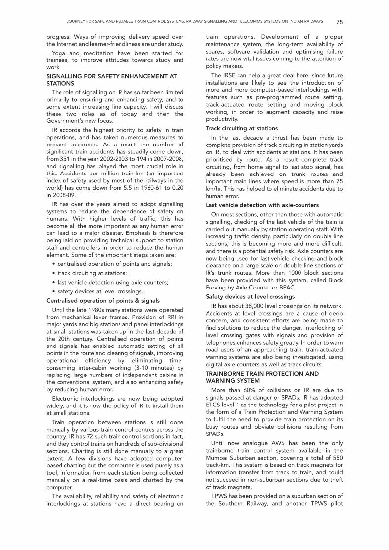
JOURNEY FOR SAFE AND RELIABLE TRAIN CONTROL SYSTEMS: RAILWAY SIGNALLING AND TELECOMMS SYSTEMS ON INDIAN RAILWAYS 75
progress. Ways of improving delivery speed overthe Internet and learner-friendliness are under study.
Yoga and meditation have been started fortrainees, to improve attitudes towards study andwork.
SIGNALLING FOR SAFETY ENHANCEMENT ATSTATIONS
The role of signalling on IR has so far been limitedprimarily to ensuring and enhancing safety, and tosome extent increasing line capacity. I will discussthese two roles as of today and then theGovernment’s new focus.
IR accords the highest priority to safety in trainoperations, and has taken numerous measures toprevent accidents. As a result the number ofsignificant train accidents has steadily come down,from 351 in the year 2002-2003 to 194 in 2007-2008,and signalling has played the most crucial role inthis. Accidents per million train-km (an importantindex of safety used by most of the railways in theworld) has come down from 5.5 in 1960-61 to 0.20in 2008-09.
IR has over the years aimed to adopt signallingsystems to reduce the dependence of safety onhumans. With higher levels of traffic, this hasbecome all the more important as any human errorcan lead to a major disaster. Emphasis is thereforebeing laid on providing technical support to stationstaff and controllers in order to reduce the humanelement. Some of the important steps taken are:
• centralised operation of points and signals;
• track circuiting at stations;
• last vehicle detection using axle counters;
• safety devices at level crossings.
Centralised operation of points & signals
Until the late 1980s many stations were operatedfrom mechanical lever frames. Provision of RRI inmajor yards and big stations and panel interlockingsat small stations was taken up in the last decade ofthe 20th century. Centralised operation of pointsand signals has enabled automatic setting of allpoints in the route and clearing of signals, improvingoperational efficiency by eliminating time-consuming inter-cabin working (3-10 minutes) byreplacing large numbers of independent cabins inthe conventional system, and also enhancing safetyby reducing human error.
Electronic interlockings are now being adoptedwidely, and it is now the policy of IR to install themat small stations.
Train operation between stations is still donemanually by various train control centres across thecountry. IR has 72 such train control sections in fact,and they control trains on hundreds of sub-divisionalsections. Charting is still done manually to a greatextent. A few divisions have adopted computer-based charting but the computer is used purely as atool, information from each station being collectedmanually on a real-time basis and charted by thecomputer.
The availability, reliability and safety of electronicinterlockings at stations have a direct bearing on
train operations. Development of a propermaintenance system, the long-term availability ofspares, software validation and optimising failurerates are now vital issues coming to the attention ofpolicy makers.
The IRSE can help a great deal here, since futureinstallations are likely to see the introduction ofmore and more computer-based interlockings withfeatures such as pre-programmed route setting,track-actuated route setting and moving blockworking, in order to augment capacity and raiseproductivity.
Track circuiting at stations
In the last decade a thrust has been made tocomplete provision of track circuiting in station yardson IR, to deal with accidents at stations. It has beenprioritised by route. As a result complete trackcircuiting, from home signal to last stop signal, hasalready been achieved on trunk routes andimportant main lines where speed is more than 75km/hr. This has helped to eliminate accidents due tohuman error.
Last vehicle detection with axle-counters
On most sections, other than those with automaticsignalling, checking of the last vehicle of the train iscarried out manually by station operating staff. Withincreasing traffic density, particularly on double linesections, this is becoming more and more difficult,and there is a potential safety risk. Axle counters arenow being used for last-vehicle checking and blockclearance on a large scale on double-line sections ofIR’s trunk routes. More than 1000 block sectionshave been provided with this system, called BlockProving by Axle Counter or BPAC.
Safety devices at level crossings
IR has about 38,000 level crossings on its network.Accidents at level crossings are a cause of deepconcern, and consistent efforts are being made tofind solutions to reduce the danger. Interlocking oflevel crossing gates with signals and provision oftelephones enhances safety greatly. In order to warnroad users of an approaching train, train-actuatedwarning systems are also being investigated, usingdigital axle counters as well as track circuits.
TRAINBORNE TRAIN PROTECTION ANDWARNING SYSTEM
More than 60% of collisions on IR are due tosignals passed at danger or SPADs. IR has adoptedETCS level 1 as the technology for a pilot project inthe form of a Train Protection and Warning Systemto fulfil the need to provide train protection on itsbusy routes and obviate collisions resulting fromSPADs.
Until now analogue AWS has been the onlytrainborne train control system available in theMumbai Suburban section, covering a total of 550track-km. This system is based on track magnets forinformation transfer from track to train, and couldnot succeed in non-suburban sections due to theftof track magnets.
TPWS has been provided on a suburban section ofthe Southern Railway, and another TPWS pilot
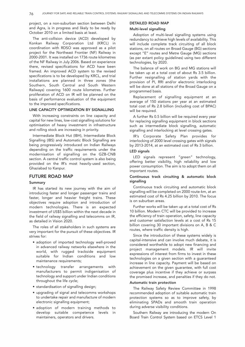
JOURNEY FOR SAFE AND RELIABLE TRAIN CONTROL SYSTEMS: RAILWAY SIGNALLING AND TELECOMMS SYSTEMS ON INDIAN RAILWAYS76
project, on a non-suburban section between Delhiand Agra, is in progress and likely to be ready byOctober 2010 on a limited basis at least.
The anti-collision device (ACD) developed byKonkan Railway Corporation Ltd (KRCL) incoordination with RDSO was approved as a pilotproject for the Northeast Frontier (NF) Railway in2000-2001. It was installed on 1736 route kilometresof the NF Railway in July 2006. Based on experiencethere, revised specifications for ACD have beenframed. An improved ACD system to the revisedspecifications is to be developed by KRCL, and trialinstallations are planned in three zones (theSouthern, South Central and South WesternRailways) covering 1600 route kilometres. Furtherproliferation of ACD on IR will be planned on thebasis of performance evaluation of the equipmentto the improved specifications.
LINE CAPACITY OPTIMIZATION BY SIGNALLING
With increasing constraints on line capacity andcapital for new lines, low-cost signalling solutions foroptimisation of heavy investment in infrastructureand rolling stock are increasing in priority.
Intermediate Block Hut (IBH), Intermediate BlockSignalling (IBS) and Automatic Block Signalling arebeing progressively introduced on Indian Railwaysdepending on the traffic requirements under themodernisation of signalling on the GZB-CNBsection. A central traffic control system is also beingprovided on the IR’s most heavily-used section,Ghaziabad to Kanpur.
FUTURE ROAD MAPSummary
IR has started its new journey with the aim ofintroducing faster and longer passenger trains andfaster, longer and heavier freight trains. Theseobjectives require adoption and introduction ofmodern technologies. There is an expectedinvestment of US$5 billion within the next decade inthe field of railway signalling and telecomms on IR,as detailed in Vision 2020.
The roles of all stakeholders in such systems arevery important for the pursuit of these objectives. IRstrives for:
• adoption of imported technology well-provedin advanced railway networks elsewhere in theworld, with rugged trackside equipmentsuitable for Indian conditions and lowmaintenance requirements;
• technology transfer arrangements withmanufacturers to permit indigenisation oftechnology and support under Indian conditionsthroughout the life cycle;
• standardisation of signalling design;
• upgrading of signal and telecomms workshopsto undertake repair and manufacture of modernelectronic signalling equipment;
• adoption of modern training methods todevelop suitable competence levels inmaintainers, operators and drivers.
DETAILED ROAD MAP
Multi-level signalling
Adoption of multi-level signalling systems usingredundancy to achieve high levels of availability. Thiswill include complete track circuiting of all blockstations, on all routes on Broad Gauge (BG) sectionsexcept “E” routes and Metre Gauge (MG) sections(as per extant policy guidelines) using two differenttechnologies, by 2020.
The balance of work on BG and MG stations willbe taken up at a total cost of about Rs 3.5 billion.Further resignalling of station yards with theprovision of PI, RRI and/or electronic interlockingwill be done at all stations of the Broad Gauge on aprogrammed basis.
Replacement of signalling equipment at anaverage of 150 stations per year at an estimatedtotal cost of Rs 2.8 billion (including cost of BPAC)will be required.
A further Rs 0.5 billion will be required every yearfor replacing signalling equipment in block sectionssuch as intermediate block signalling, automaticsignalling and interlocking at level crossing gates.
IR’s Corporate Safety Plan provides forinterlocking of 2000 level crossing gates with signalsby 2013-2014, at an estimated cost of Rs 3 billion.
LED signals
LED signals represent “green” technology,offering better visibility, high reliability and lowpower consumption. The aim is to adopt them on allimportant routes.
Continuous track circuiting & automatic blocksignalling
Continuous track circuiting and automatic blocksignalling will be completed on 2000 route-km, at anestimated cost of Rs 4.25 billion by 2010. The focusis on suburban areas.
Further works will be taken up at a total cost of Rs10 billion. Modern CTC will be provided to increasethe efficiency of train operation, safety, line capacityand customer satisfaction levels at a cost of Rs 15billion covering 30 important divisions on A, B & Croutes, where traffic density is high.
Since the introduction of these systems widely iscapital-intensive and can involve much debate, it isconsidered worthwhile to adopt new financing andproject management models. IR will inviteexpressions of interest from firms to invest in thesetechnologies on a given section with a guaranteedincrease in line capacity. Payment will be based onachievement on the given guarantee, with full costcoverage plus incentive if they achieve or surpassthe promised increase, and penalties if they do not.
Automatic train protection
The Railway Safety Review Committee in 1998recommended adoption of suitable automatic trainprotection systems so as to improve safety, byeliminating SPADs and smooth train operationduring adverse visibility conditions.
Southern Railway are introducing the modern OnBoard Train Control System based on ETCS Level 1
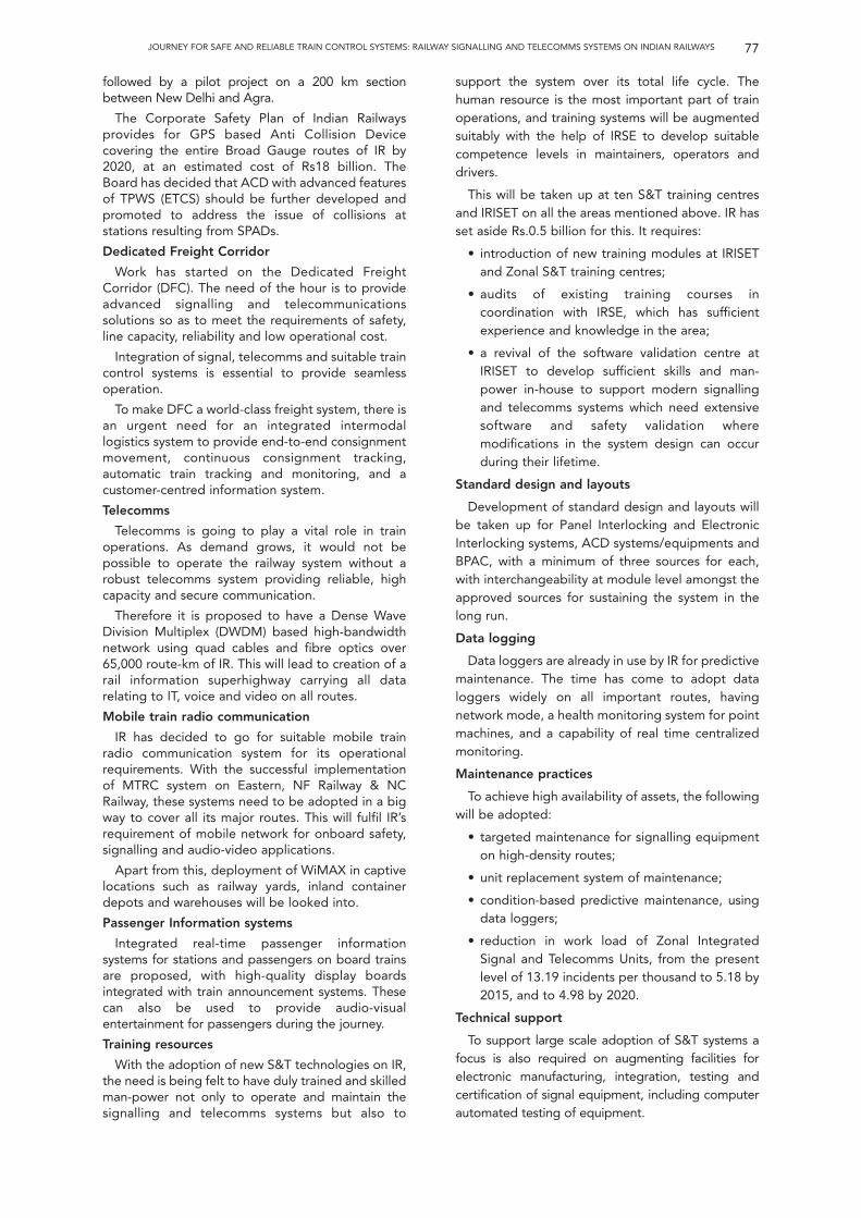
followed by a pilot project on a 200 km sectionbetween New Delhi and Agra.
The Corporate Safety Plan of Indian Railwaysprovides for GPS based Anti Collision Devicecovering the entire Broad Gauge routes of IR by2020, at an estimated cost of Rs18 billion. TheBoard has decided that ACD with advanced featuresof TPWS (ETCS) should be further developed andpromoted to address the issue of collisions atstations resulting from SPADs.
Dedicated Freight Corridor
Work has started on the Dedicated FreightCorridor (DFC). The need of the hour is to provideadvanced signalling and telecommunicationssolutions so as to meet the requirements of safety,line capacity, reliability and low operational cost.
Integration of signal, telecomms and suitable traincontrol systems is essential to provide seamlessoperation.
To make DFC a world-class freight system, there isan urgent need for an integrated intermodallogistics system to provide end-to-end consignmentmovement, continuous consignment tracking,automatic train tracking and monitoring, and acustomer-centred information system.
Telecomms
Telecomms is going to play a vital role in trainoperations. As demand grows, it would not bepossible to operate the railway system without arobust telecomms system providing reliable, highcapacity and secure communication.
Therefore it is proposed to have a Dense WaveDivision Multiplex (DWDM) based high-bandwidthnetwork using quad cables and fibre optics over65,000 route-km of IR. This will lead to creation of arail information superhighway carrying all datarelating to IT, voice and video on all routes.
Mobile train radio communication
IR has decided to go for suitable mobile trainradio communication system for its operationalrequirements. With the successful implementationof MTRC system on Eastern, NF Railway & NCRailway, these systems need to be adopted in a bigway to cover all its major routes. This will fulfil IR’srequirement of mobile network for onboard safety,signalling and audio-video applications.
Apart from this, deployment of WiMAX in captivelocations such as railway yards, inland containerdepots and warehouses will be looked into.
Passenger Information systems
Integrated real-time passenger informationsystems for stations and passengers on board trainsare proposed, with high-quality display boardsintegrated with train announcement systems. Thesecan also be used to provide audio-visualentertainment for passengers during the journey.
Training resources
With the adoption of new S&T technologies on IR,the need is being felt to have duly trained and skilledman-power not only to operate and maintain thesignalling and telecomms systems but also to
support the system over its total life cycle. Thehuman resource is the most important part of trainoperations, and training systems will be augmentedsuitably with the help of IRSE to develop suitablecompetence levels in maintainers, operators anddrivers.
This will be taken up at ten S&T training centresand IRISET on all the areas mentioned above. IR hasset aside Rs.0.5 billion for this. It requires:
• introduction of new training modules at IRISETand Zonal S&T training centres;
• audits of existing training courses incoordination with IRSE, which has sufficientexperience and knowledge in the area;
• a revival of the software validation centre atIRISET to develop sufficient skills and man-power in-house to support modern signallingand telecomms systems which need extensivesoftware and safety validation wheremodifications in the system design can occurduring their lifetime.
Standard design and layouts
Development of standard design and layouts willbe taken up for Panel Interlocking and ElectronicInterlocking systems, ACD systems/equipments andBPAC, with a minimum of three sources for each,with interchangeability at module level amongst theapproved sources for sustaining the system in thelong run.
Data logging
Data loggers are already in use by IR for predictivemaintenance. The time has come to adopt dataloggers widely on all important routes, havingnetwork mode, a health monitoring system for pointmachines, and a capability of real time centralizedmonitoring.
Maintenance practices
To achieve high availability of assets, the followingwill be adopted:
• targeted maintenance for signalling equipmenton high-density routes;
• unit replacement system of maintenance;
• condition-based predictive maintenance, usingdata loggers;
• reduction in work load of Zonal IntegratedSignal and Telecomms Units, from the presentlevel of 13.19 incidents per thousand to 5.18 by2015, and to 4.98 by 2020.
Technical support
To support large scale adoption of S&T systems afocus is also required on augmenting facilities forelectronic manufacturing, integration, testing andcertification of signal equipment, including computerautomated testing of equipment.
77JOURNEY FOR SAFE AND RELIABLE TRAIN CONTROL SYSTEMS: RAILWAY SIGNALLING AND TELECOMMS SYSTEMS ON INDIAN RAILWAYS

78 JOURNEY FOR SAFE AND RELIABLE TRAIN CONTROL SYSTEMS: RAILWAY SIGNALLING AND TELECOMMS SYSTEMS ON INDIAN RAILWAYS
Figure 1 Map of Indian Railways
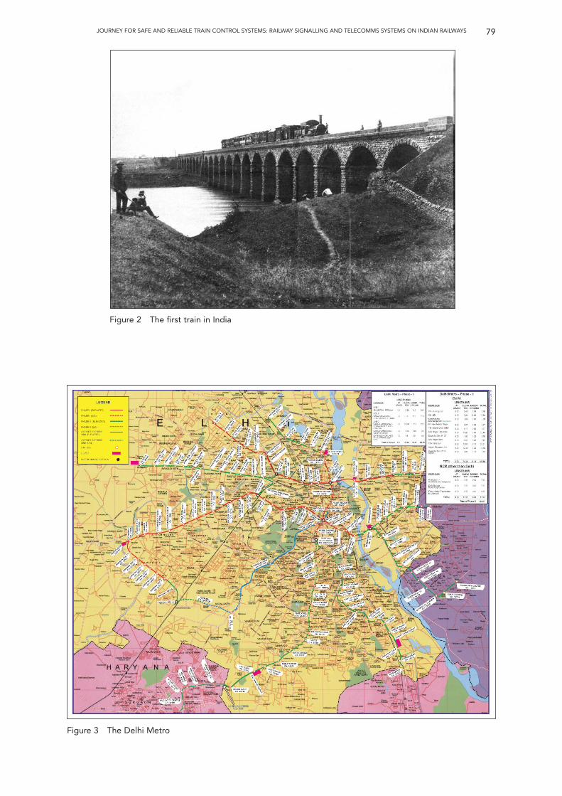
79JOURNEY FOR SAFE AND RELIABLE TRAIN CONTROL SYSTEMS: RAILWAY SIGNALLING AND TELECOMMS SYSTEMS ON INDIAN RAILWAYS
Figure 3 The Delhi Metro
Figure 2 The first train in India
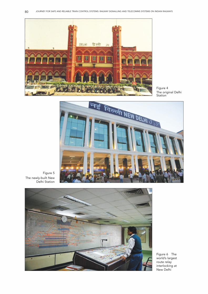
80 JOURNEY FOR SAFE AND RELIABLE TRAIN CONTROL SYSTEMS: RAILWAY SIGNALLING AND TELECOMMS SYSTEMS ON INDIAN RAILWAYS
Figure 4 The original DelhiStation
Figure 5
The newly-built NewDelhi Station
Figure 6 Theworld’s largestroute relayinterlocking atNew Delhi
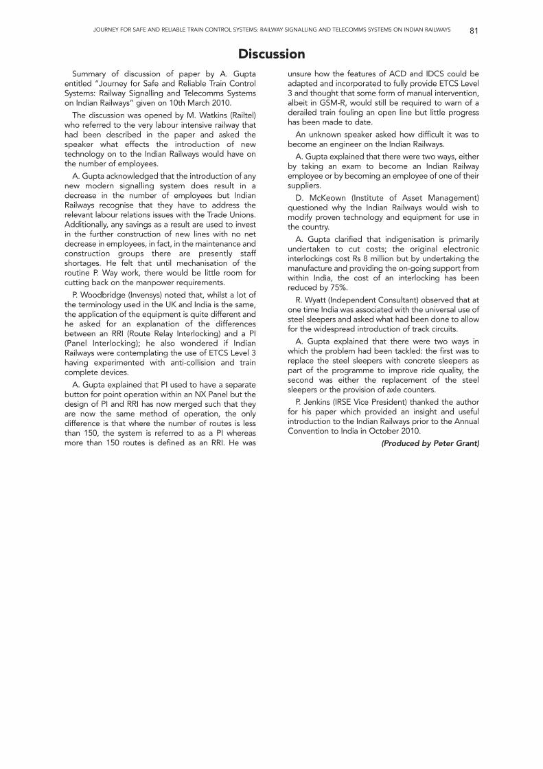
81JOURNEY FOR SAFE AND RELIABLE TRAIN CONTROL SYSTEMS: RAILWAY SIGNALLING AND TELECOMMS SYSTEMS ON INDIAN RAILWAYS
DiscussionSummary of discussion of paper by A. Gupta
entitled “Journey for Safe and Reliable Train ControlSystems: Railway Signalling and Telecomms Systemson Indian Railways” given on 10th March 2010.
The discussion was opened by M. Watkins (Railtel)who referred to the very labour intensive railway thathad been described in the paper and asked thespeaker what effects the introduction of newtechnology on to the Indian Railways would have onthe number of employees.
A. Gupta acknowledged that the introduction of anynew modern signalling system does result in adecrease in the number of employees but IndianRailways recognise that they have to address therelevant labour relations issues with the Trade Unions.Additionally, any savings as a result are used to investin the further construction of new lines with no netdecrease in employees, in fact, in the maintenance andconstruction groups there are presently staffshortages. He felt that until mechanisation of theroutine P. Way work, there would be little room forcutting back on the manpower requirements.
P. Woodbridge (Invensys) noted that, whilst a lot ofthe terminology used in the UK and India is the same,the application of the equipment is quite different andhe asked for an explanation of the differencesbetween an RRI (Route Relay Interlocking) and a PI(Panel Interlocking); he also wondered if IndianRailways were contemplating the use of ETCS Level 3having experimented with anti-collision and traincomplete devices.
A. Gupta explained that PI used to have a separatebutton for point operation within an NX Panel but thedesign of PI and RRI has now merged such that theyare now the same method of operation, the onlydifference is that where the number of routes is lessthan 150, the system is referred to as a PI whereasmore than 150 routes is defined as an RRI. He was
unsure how the features of ACD and IDCS could beadapted and incorporated to fully provide ETCS Level3 and thought that some form of manual intervention,albeit in GSM-R, would still be required to warn of aderailed train fouling an open line but little progresshas been made to date.
An unknown speaker asked how difficult it was tobecome an engineer on the Indian Railways.
A. Gupta explained that there were two ways, eitherby taking an exam to become an Indian Railwayemployee or by becoming an employee of one of theirsuppliers.
D. McKeown (Institute of Asset Management)questioned why the Indian Railways would wish tomodify proven technology and equipment for use inthe country.
A. Gupta clarified that indigenisation is primarilyundertaken to cut costs; the original electronicinterlockings cost Rs 8 million but by undertaking themanufacture and providing the on-going support fromwithin India, the cost of an interlocking has beenreduced by 75%.
R. Wyatt (Independent Consultant) observed that atone time India was associated with the universal use ofsteel sleepers and asked what had been done to allowfor the widespread introduction of track circuits.
A. Gupta explained that there were two ways inwhich the problem had been tackled: the first was toreplace the steel sleepers with concrete sleepers aspart of the programme to improve ride quality, thesecond was either the replacement of the steelsleepers or the provision of axle counters.
P. Jenkins (IRSE Vice President) thanked the authorfor his paper which provided an insight and usefulintroduction to the Indian Railways prior to the AnnualConvention to India in October 2010.
(Produced by Peter Grant)
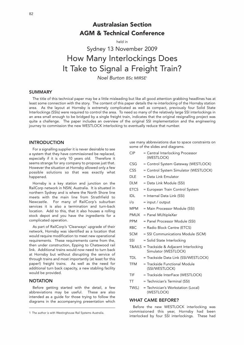
82
Australasian SectionAGM & Technical Conference
held in
Sydney 13 November 2009
How Many Interlockings DoesIt Take to Signal a Freight Train?
Noel Burton BSc MIRSE1
INTRODUCTIONFor a signalling supplier it is never desirable to see
a system that they have commissioned be replaced,especially if it is only 10 years old. Therefore itseems strange for any company to propose just that.However the situation at Hornsby allowed only a fewpossible solutions so that was exactly whathappened.
Hornsby is a key station and junction on theRailCorp network in NSW, Australia. It is situated innorthern Sydney and is where the North Shore linemeets with the main line from Strathfield toNewcastle. For many of RailCorp’s suburbanservices it is also a termination and turn-backlocation. Add to this, that it also houses a rollingstock depot and you have the ingredients for acomplicated operation.
As part of RailCorp’s ‘Clearways’ upgrade of theirnetwork, Hornsby was identified as a location thatwould require modification to meet new operationalrequirements. These requirements came from the,then under construction, Epping to Chatswood raillink. Additional trains would now need to turn backat Hornsby but without disrupting the service ofthrough trains and most importantly (at least for thispaper!) freight trains. As well as the need foradditional turn back capacity, a new stabling facilitywould be provided.
NOTATIONBefore getting started with the detail, a few
abbreviations may be useful. These are alsointended as a guide for those trying to follow thediagrams in the accompanying presentation which
use many abbreviations due to space constraints onsome of the slides and diagrams.
CIP = Central Interlocking Processor (WESTLOCK)
CSG = Control System Gateway (WESTLOCK)
CSS = Control System Simulator (WESTLOCK)
DLE = Data Link Emulator
DLM = Data Link Module (SSI)
ETCS = European Train Control System
IDL = Internal Data Link (SSI)
i/o = input / output
MPM = Main Processor Module (SSI)
PMUX = Panel MUltipleXer
PPM = Panel Processor Module (SSI)
RBC = Radio Block Centre (ETCS)
SCM = SSI Communications Module (SCM)
SSI = Solid State Interlocking
T&AILS = Trackside & Adjacent Interlocking Simulator (WESTLOCK)
TDL = Trackside Data Link (SSI/WESTLOCK)
TFM = Trackside Functional Module (SSI/WESTLOCK)
TIF = Trackside InterFace (WESTLOCK)
TT = Technician’s Terminal (SSI)
TW(L) = Technician’s Workstation (Local)(WESTLOCK)
WHAT CAME BEFORE?Before the new WESTLOCK interlocking was
commissioned this year, Hornsby had beeninterlocked by four SSI interlockings. These had
SUMMARYThe title of this technical paper may be a little misleading but like all good attention grabbing headlines has at
least some connection with the story. The content of this paper details the re-interlocking of the Hornsby stationarea. As the layout at Hornsby is extremely complicated as well as compact, previously four Solid StateInterlockings (SSIs) were required to control the area. To need so many of the relatively large SSI interlockings inan area small enough to be bridged by a single freight train, indicates that the original resignalling project wasquite a challenge. The paper includes an overview of the original SSI implementation and the engineeringjourney to commission the new WESTLOCK interlocking to eventually reduce that number.
1 The author is with Westinghouse Rail Systems Australia.
been installed by Westinghouse Signals Australia in1999 as part of a full re-signalling of the Hornsbystation area. The area covered by the interlockingsincluded the close approaches from the south and areasonable length of automatic signalled section tothe north.
Compared to other layouts of equivalentgeographical length and breath, four SSIs may haveseemed excessive. The opposite was actually true,with the sheer number of routes through the heartof the junction mixed with full braking lengthswinging overlaps used by NSW signallingprinciples, contributing to data that was some of the(if not the most) complex in the world.
As soon as they were commissioned, the four SSIsat Hornsby were full. The central two were atabsolute capacity, with the original data havingbeen skilfully re-written many times during theoriginal design phase to make it “fit in”!
5th PLATFORM AND STABLING YARDPROJECT
In 2006 WRSA were awarded the contract for thesignalling works on the Hornsby 5th Platform andStabling yards upgrade project. During thetendering for this work, the core technical challengewas how to add the new routes and additionalsignalling objects without having to renew the entiresignalling system. Normally with SSI this would be asimple case of adding some more data and slottingin some new object controllers. The problem withthis project was that the areas where the new workswere going to be installed coincided with the twoSSIs that were at capacity already.
It appeared that the only remotely cost effectivemethod would be to add a fifth SSI to provide theadditional capacity. The problem with this solutionwas that the two existing central SSIs were not justat their data limits but also their cross boundary datalimits. Adding a fifth SSI would only work if all of thedata from the existing interlockings was scrappedand new, even more complex, interlockingboundaries were demarked. This obviously wouldbe akin to starting the job again.
WRSA suggested that there may be a secondoption. WESTLOCK was a new product that wasjust about to go into an operation pilot atLeamington Spa in the UK. WESTLOCK would allowthe four existing SSIs to be replaced with one singlemassive pseudo-SSI interlocking. WESTLOCK hadthree key features that made it ideal for this project:
• An interlocking capacity of over 4 SSIs.Therefore it would easily encompass all theexisting data, plus the new. It would also allowthe deletion of the verbose and extremelycomplex cross boundary SSI data which was acore limitation on the expansion of the existingsystem.
• It could use standard SSI trackside objectcontrollers and data links. This meant that theexisting trackside signalling SSI assets could beretained and new equipment would only be
required for the new track work areas.
• It uses a data language that is the same as theone used to program SSI. This would allow theold data to be reused, thereby reducing thedesign effort.
Despite the fact that this was a new and largelyunproven technology, it was seen as the onlyreasonable solution. The risk of the new technologycould also be mitigated by pre-commissioningtesting as the WESTLOCK could be used to controlthe existing layout during possessions. This isexplained in more detail later in the paper.
THE NEW INTERLOCKING SYSTEMThe remainder of this paper sets out to detail the
system that was provided, its differences from theprevious SSI interlocking and engineeringchallenges that were met on course to the finalcommissioning.
Before delving into the detail of the systemarchitecture at Hornsby, it is worthwhile taking astep back to consider some of the commoninterlocking architectures used as a bit of usefulback ground discussion.
TYPICAL INTERLOCKING ARCHITECTURES
In the age of the Computer Based Interlocking(CBI) there are now a number of different options onhow to arrange an interlocking and its associatedinput/output (i/o). There are three commonarchitectures commonly used, they are:
• Centralised interlocking, centralised i/o;
• Centralised interlocking, distributed i/o; and
• Distributed interlocking, distributed i/o.
All three architectures are used in a reasonablyeven ratio worldwide so there are obviously benefitsand drawbacks to each of the different approaches.
British Rail’s Solid State Interlocking (SSI) is a CBIwhich used the second of these architectures. Theinterlocking is centralised in a single housing with truedistribution of its i/o made possible by the provisionof a vital data link and standard, non-programmable,slave object controllers. Assuming power is alreadyavailable at each location, this means that in theoryonly two, one-pair copper communications cablesneed be installed along the trackside.
The benefits of a distributed i/o arrangement areobvious but not always easy to realise. Thearchitecture is ideal for long thin layouts, wheredirect cabling from a few centralised interlockings isextremely wasteful in terms of cable and associatedducting.
WESTLOCK allowed for this architecture to beretained at Hornsby, and we will revisit whether thiswas the best arrangement later in the paper.
‘THE NEW’ VS ‘THE OLD’
So what has actually changed at Hornsby? Thesupposed benefit of WESTLOCK, which allows thecustomer to retain most of an existing SSIinstallation, begs the question as to what actuallychanges.
83HOW MANY INTERLOCKINGS DOES IT TAKE TO SIGNAL A FREIGHT TRAIN?
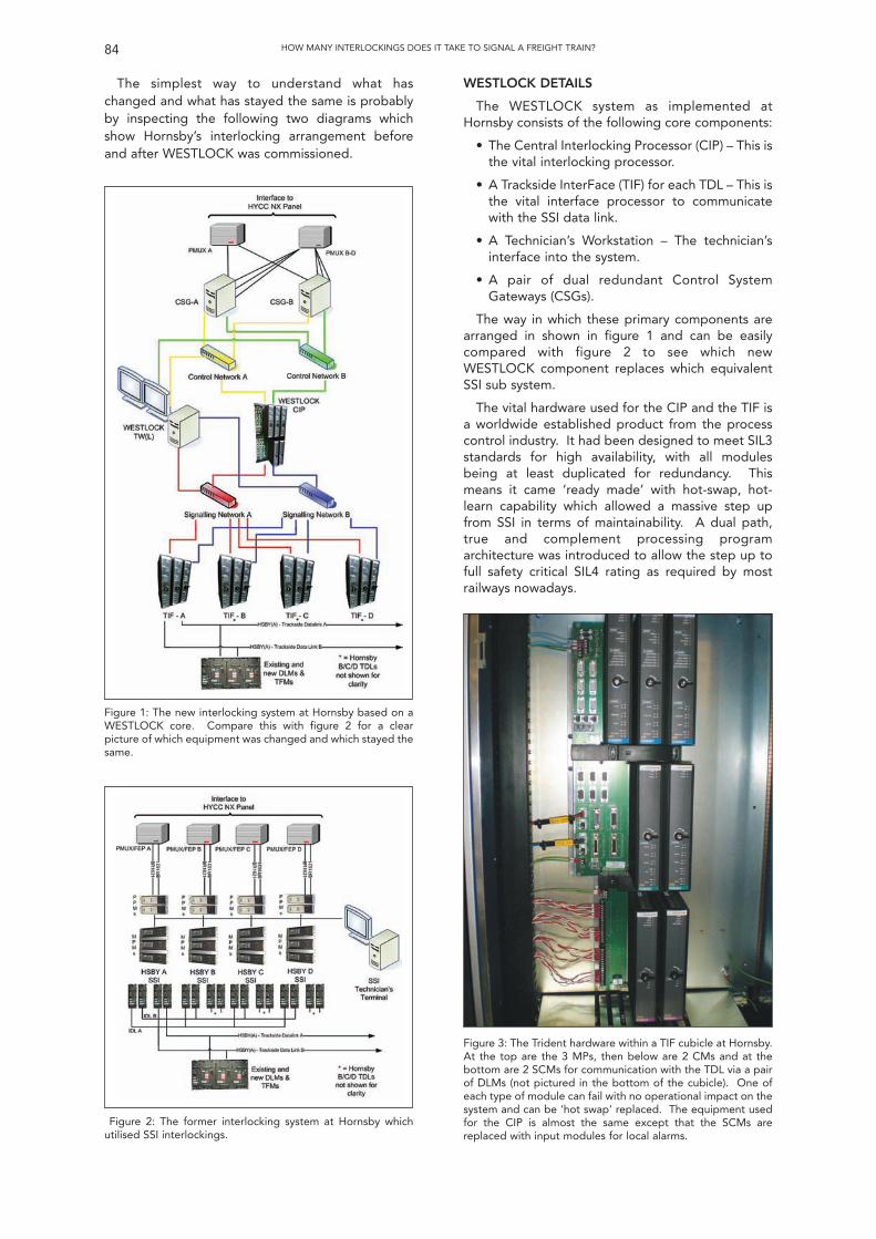
The simplest way to understand what haschanged and what has stayed the same is probablyby inspecting the following two diagrams whichshow Hornsby’s interlocking arrangement beforeand after WESTLOCK was commissioned.
WESTLOCK DETAILS
The WESTLOCK system as implemented atHornsby consists of the following core components:
• The Central Interlocking Processor (CIP) – This isthe vital interlocking processor.
• A Trackside InterFace (TIF) for each TDL – This isthe vital interface processor to communicatewith the SSI data link.
• A Technician’s Workstation – The technician’sinterface into the system.
• A pair of dual redundant Control SystemGateways (CSGs).
The way in which these primary components arearranged in shown in figure 1 and can be easilycompared with figure 2 to see which newWESTLOCK component replaces which equivalentSSI sub system.
The vital hardware used for the CIP and the TIF isa worldwide established product from the processcontrol industry. It had been designed to meet SIL3standards for high availability, with all modulesbeing at least duplicated for redundancy. Thismeans it came ‘ready made’ with hot-swap, hot-learn capability which allowed a massive step upfrom SSI in terms of maintainability. A dual path,true and complement processing programarchitecture was introduced to allow the step up tofull safety critical SIL4 rating as required by mostrailways nowadays.
84 HOW MANY INTERLOCKINGS DOES IT TAKE TO SIGNAL A FREIGHT TRAIN?
Figure 1: The new interlocking system at Hornsby based on aWESTLOCK core. Compare this with figure 2 for a clearpicture of which equipment was changed and which stayed thesame.
Figure 2: The former interlocking system at Hornsby whichutilised SSI interlockings.
Figure 3: The Trident hardware within a TIF cubicle at Hornsby.At the top are the 3 MPs, then below are 2 CMs and at thebottom are 2 SCMs for communication with the TDL via a pairof DLMs (not pictured in the bottom of the cubicle). One ofeach type of module can fail with no operational impact on thesystem and can be ‘hot swap’ replaced. The equipment usedfor the CIP is almost the same except that the SCMs arereplaced with input modules for local alarms.
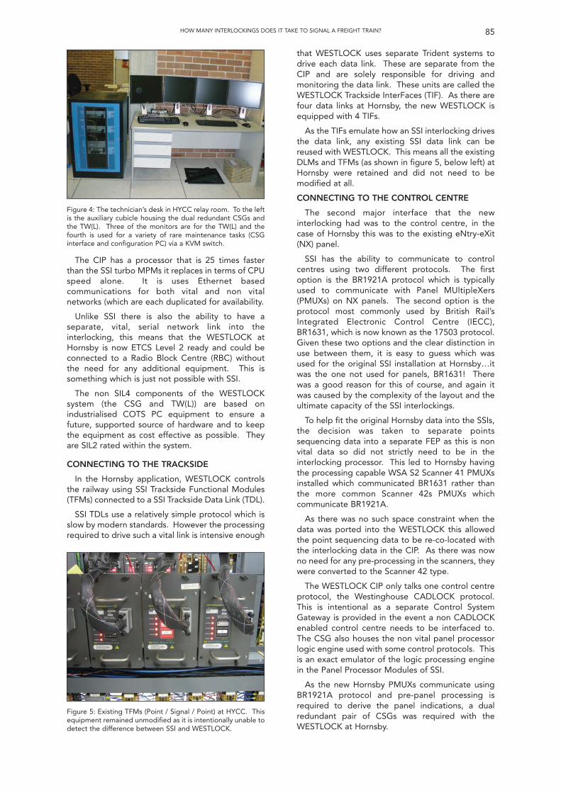
The CIP has a processor that is 25 times fasterthan the SSI turbo MPMs it replaces in terms of CPUspeed alone. It is uses Ethernet basedcommunications for both vital and non vitalnetworks (which are each duplicated for availability.
Unlike SSI there is also the ability to have aseparate, vital, serial network link into theinterlocking, this means that the WESTLOCK atHornsby is now ETCS Level 2 ready and could beconnected to a Radio Block Centre (RBC) withoutthe need for any additional equipment. This issomething which is just not possible with SSI.
The non SIL4 components of the WESTLOCKsystem (the CSG and TW(L)) are based onindustrialised COTS PC equipment to ensure afuture, supported source of hardware and to keepthe equipment as cost effective as possible. Theyare SIL2 rated within the system.
CONNECTING TO THE TRACKSIDE
In the Hornsby application, WESTLOCK controlsthe railway using SSI Trackside Functional Modules(TFMs) connected to a SSI Trackside Data Link (TDL).
SSI TDLs use a relatively simple protocol which isslow by modern standards. However the processingrequired to drive such a vital link is intensive enough
that WESTLOCK uses separate Trident systems todrive each data link. These are separate from theCIP and are solely responsible for driving andmonitoring the data link. These units are called theWESTLOCK Trackside InterFaces (TIF). As there arefour data links at Hornsby, the new WESTLOCK isequipped with 4 TIFs.
As the TIFs emulate how an SSI interlocking drivesthe data link, any existing SSI data link can bereused with WESTLOCK. This means all the existingDLMs and TFMs (as shown in figure 5, below left) atHornsby were retained and did not need to bemodified at all.
CONNECTING TO THE CONTROL CENTRE
The second major interface that the newinterlocking had was to the control centre, in thecase of Hornsby this was to the existing eNtry-eXit(NX) panel.
SSI has the ability to communicate to controlcentres using two different protocols. The firstoption is the BR1921A protocol which is typicallyused to communicate with Panel MUltipleXers(PMUXs) on NX panels. The second option is theprotocol most commonly used by British Rail’sIntegrated Electronic Control Centre (IECC),BR1631, which is now known as the 17503 protocol.Given these two options and the clear distinction inuse between them, it is easy to guess which wasused for the original SSI installation at Hornsby…itwas the one not used for panels, BR1631! Therewas a good reason for this of course, and again itwas caused by the complexity of the layout and theultimate capacity of the SSI interlockings.
To help fit the original Hornsby data into the SSIs,the decision was taken to separate pointssequencing data into a separate FEP as this is nonvital data so did not strictly need to be in theinterlocking processor. This led to Hornsby havingthe processing capable WSA S2 Scanner 41 PMUXsinstalled which communicated BR1631 rather thanthe more common Scanner 42s PMUXs whichcommunicate BR1921A.
As there was no such space constraint when thedata was ported into the WESTLOCK this allowedthe point sequencing data to be re-co-located withthe interlocking data in the CIP. As there was nowno need for any pre-processing in the scanners, theywere converted to the Scanner 42 type.
The WESTLOCK CIP only talks one control centreprotocol, the Westinghouse CADLOCK protocol.This is intentional as a separate Control SystemGateway is provided in the event a non CADLOCKenabled control centre needs to be interfaced to.The CSG also houses the non vital panel processorlogic engine used with some control protocols. Thisis an exact emulator of the logic processing enginein the Panel Processor Modules of SSI.
As the new Hornsby PMUXs communicate usingBR1921A protocol and pre-panel processing isrequired to derive the panel indications, a dualredundant pair of CSGs was required with theWESTLOCK at Hornsby.
85HOW MANY INTERLOCKINGS DOES IT TAKE TO SIGNAL A FREIGHT TRAIN?
Figure 4: The technician’s desk in HYCC relay room. To the leftis the auxiliary cubicle housing the dual redundant CSGs andthe TW(L). Three of the monitors are for the TW(L) and thefourth is used for a variety of rare maintenance tasks (CSGinterface and configuration PC) via a KVM switch.
Figure 5: Existing TFMs (Point / Signal / Point) at HYCC. Thisequipment remained unmodified as it is intentionally unable todetect the difference between SSI and WESTLOCK.
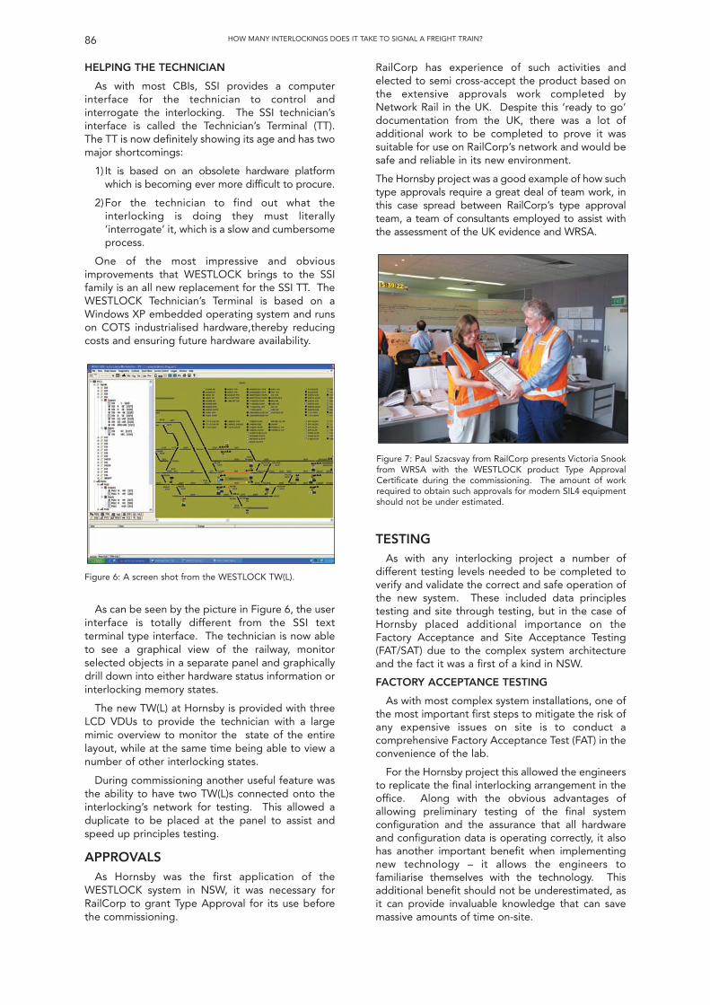
HELPING THE TECHNICIAN
As with most CBIs, SSI provides a computerinterface for the technician to control andinterrogate the interlocking. The SSI technician’sinterface is called the Technician’s Terminal (TT).The TT is now definitely showing its age and has twomajor shortcomings:
1) It is based on an obsolete hardware platformwhich is becoming ever more difficult to procure.
2)For the technician to find out what theinterlocking is doing they must literally‘interrogate’ it, which is a slow and cumbersomeprocess.
One of the most impressive and obviousimprovements that WESTLOCK brings to the SSIfamily is an all new replacement for the SSI TT. TheWESTLOCK Technician’s Terminal is based on aWindows XP embedded operating system and runson COTS industrialised hardware,thereby reducingcosts and ensuring future hardware availability.
RailCorp has experience of such activities andelected to semi cross-accept the product based onthe extensive approvals work completed byNetwork Rail in the UK. Despite this ‘ready to go’documentation from the UK, there was a lot ofadditional work to be completed to prove it wassuitable for use on RailCorp’s network and would besafe and reliable in its new environment.
The Hornsby project was a good example of how suchtype approvals require a great deal of team work, inthis case spread between RailCorp’s type approvalteam, a team of consultants employed to assist withthe assessment of the UK evidence and WRSA.
86 HOW MANY INTERLOCKINGS DOES IT TAKE TO SIGNAL A FREIGHT TRAIN?
Figure 6: A screen shot from the WESTLOCK TW(L).
As can be seen by the picture in Figure 6, the userinterface is totally different from the SSI textterminal type interface. The technician is now ableto see a graphical view of the railway, monitorselected objects in a separate panel and graphicallydrill down into either hardware status information orinterlocking memory states.
The new TW(L) at Hornsby is provided with threeLCD VDUs to provide the technician with a largemimic overview to monitor the state of the entirelayout, while at the same time being able to view anumber of other interlocking states.
During commissioning another useful feature wasthe ability to have two TW(L)s connected onto theinterlocking’s network for testing. This allowed aduplicate to be placed at the panel to assist andspeed up principles testing.
APPROVALSAs Hornsby was the first application of the
WESTLOCK system in NSW, it was necessary forRailCorp to grant Type Approval for its use beforethe commissioning.
Figure 7: Paul Szacsvay from RailCorp presents Victoria Snookfrom WRSA with the WESTLOCK product Type ApprovalCertificate during the commissioning. The amount of workrequired to obtain such approvals for modern SIL4 equipmentshould not be under estimated.
TESTINGAs with any interlocking project a number of
different testing levels needed to be completed toverify and validate the correct and safe operation ofthe new system. These included data principlestesting and site through testing, but in the case ofHornsby placed additional importance on theFactory Acceptance and Site Acceptance Testing(FAT/SAT) due to the complex system architectureand the fact it was a first of a kind in NSW.
FACTORY ACCEPTANCE TESTING
As with most complex system installations, one ofthe most important first steps to mitigate the risk ofany expensive issues on site is to conduct acomprehensive Factory Acceptance Test (FAT) in theconvenience of the lab.
For the Hornsby project this allowed the engineersto replicate the final interlocking arrangement in theoffice. Along with the obvious advantages ofallowing preliminary testing of the final systemconfiguration and the assurance that all hardwareand configuration data is operating correctly, it alsohas another important benefit when implementingnew technology – it allows the engineers tofamiliarise themselves with the technology. Thisadditional benefit should not be underestimated, asit can provide invaluable knowledge that can savemassive amounts of time on-site.
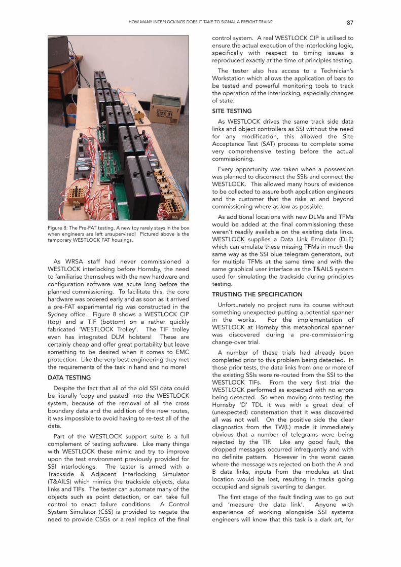
As WRSA staff had never commissioned aWESTLOCK interlocking before Hornsby, the needto familiarise themselves with the new hardware andconfiguration software was acute long before theplanned commissioning. To facilitate this, the corehardware was ordered early and as soon as it arriveda pre-FAT experimental rig was constructed in theSydney office. Figure 8 shows a WESTLOCK CIP(top) and a TIF (bottom) on a rather quicklyfabricated ‘WESTLOCK Trolley’. The TIF trolleyeven has integrated DLM holsters! These arecertainly cheap and offer great portability but leavesomething to be desired when it comes to EMCprotection. Like the very best engineering they metthe requirements of the task in hand and no more!
DATA TESTING
Despite the fact that all of the old SSI data couldbe literally ‘copy and pasted’ into the WESTLOCKsystem, because of the removal of all the crossboundary data and the addition of the new routes,it was impossible to avoid having to re-test all of thedata.
Part of the WESTLOCK support suite is a fullcomplement of testing software. Like many thingswith WESTLOCK these mimic and try to improveupon the test environment previously provided forSSI interlockings. The tester is armed with aTrackside & Adjacent Interlocking Simulator(T&AILS) which mimics the trackside objects, datalinks and TIFs. The tester can automate many of theobjects such as point detection, or can take fullcontrol to enact failure conditions. A ControlSystem Simulator (CSS) is provided to negate theneed to provide CSGs or a real replica of the final
control system. A real WESTLOCK CIP is utilised toensure the actual execution of the interlocking logic,specifically with respect to timing issues isreproduced exactly at the time of principles testing.
The tester also has access to a Technician’sWorkstation which allows the application of bars tobe tested and powerful monitoring tools to trackthe operation of the interlocking, especially changesof state.
SITE TESTING
As WESTLOCK drives the same track side datalinks and object controllers as SSI without the needfor any modification, this allowed the SiteAcceptance Test (SAT) process to complete somevery comprehensive testing before the actualcommissioning.
Every opportunity was taken when a possessionwas planned to disconnect the SSIs and connect theWESTLOCK. This allowed many hours of evidenceto be collected to assure both application engineersand the customer that the risks at and beyondcommissioning where as low as possible.
As additional locations with new DLMs and TFMswould be added at the final commissioning theseweren’t readily available on the existing data links.WESTLOCK supplies a Data Link Emulator (DLE)which can emulate these missing TFMs in much thesame way as the SSI blue telegram generators, butfor multiple TFMs at the same time and with thesame graphical user interface as the T&AILS systemused for simulating the trackside during principlestesting.
TRUSTING THE SPECIFICATION
Unfortunately no project runs its course withoutsomething unexpected putting a potential spannerin the works. For the implementation ofWESTLOCK at Hornsby this metaphorical spannerwas discovered during a pre-commissioningchange-over trial.
A number of these trials had already beencompleted prior to this problem being detected. Inthose prior tests, the data links from one or more ofthe existing SSIs were re-routed from the SSI to theWESTLOCK TIFs. From the very first trial theWESTLOCK performed as expected with no errorsbeing detected. So when moving onto testing theHornsby ‘D’ TDL it was with a great deal of(unexpected) consternation that it was discoveredall was not well. On the positive side the cleardiagnostics from the TW(L) made it immediatelyobvious that a number of telegrams were beingrejected by the TIF. Like any good fault, thedropped messages occurred infrequently and withno definite pattern. However in the worst caseswhere the message was rejected on both the A andB data links, inputs from the modules at thatlocation would be lost, resulting in tracks goingoccupied and signals reverting to danger.
The first stage of the fault finding was to go outand ‘measure the data link’. Anyone withexperience of working alongside SSI systemsengineers will know that this task is a dark art, for
87HOW MANY INTERLOCKINGS DOES IT TAKE TO SIGNAL A FREIGHT TRAIN?
Figure 8: The Pre-FAT testing. A new toy rarely stays in the boxwhen engineers are left unsupervised! Pictured above is thetemporary WESTLOCK FAT housings.
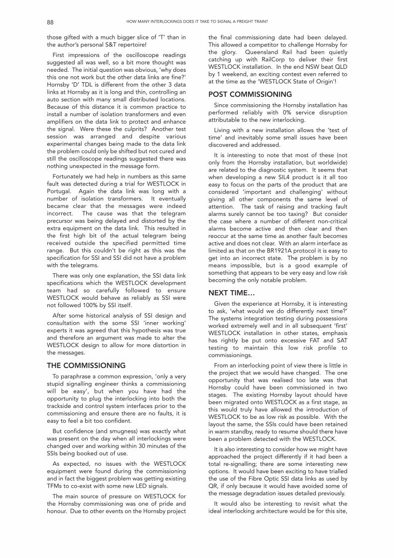
those gifted with a much bigger slice of ‘T’ than inthe author’s personal S&T repertoire!
First impressions of the oscilloscope readingssuggested all was well, so a bit more thought wasneeded. The initial question was obvious, ‘why doesthis one not work but the other data links are fine?’Hornsby ‘D’ TDL is different from the other 3 datalinks at Hornsby as it is long and thin, controlling anauto section with many small distributed locations.Because of this distance it is common practice toinstall a number of isolation transformers and evenamplifiers on the data link to protect and enhancethe signal. Were these the culprits? Another testsession was arranged and despite variousexperimental changes being made to the data linkthe problem could only be shifted but not cured andstill the oscilloscope readings suggested there wasnothing unexpected in the message form.
Fortunately we had help in numbers as this samefault was detected during a trial for WESTLOCK inPortugal. Again the data link was long with anumber of isolation transformers. It eventuallybecame clear that the messages were indeedincorrect. The cause was that the telegramprecursor was being delayed and distorted by theextra equipment on the data link. This resulted inthe first high bit of the actual telegram beingreceived outside the specified permitted timerange. But this couldn’t be right as this was thespecification for SSI and SSI did not have a problemwith the telegrams.
There was only one explanation, the SSI data linkspecifications which the WESTLOCK developmentteam had so carefully followed to ensureWESTLOCK would behave as reliably as SSI werenot followed 100% by SSI itself.
After some historical analysis of SSI design andconsultation with the some SSI ‘inner working’experts it was agreed that this hypothesis was trueand therefore an argument was made to alter theWESTLOCK design to allow for more distortion inthe messages.
THE COMMISSIONINGTo paraphrase a common expression, ‘only a very
stupid signalling engineer thinks a commissioningwill be easy’, but when you have had theopportunity to plug the interlocking into both thetrackside and control system interfaces prior to thecommissioning and ensure there are no faults, it iseasy to feel a bit too confident.
But confidence (and smugness) was exactly whatwas present on the day when all interlockings werechanged over and working within 30 minutes of theSSIs being booked out of use.
As expected, no issues with the WESTLOCKequipment were found during the commissioningand in fact the biggest problem was getting existingTFMs to co-exist with some new LED signals.
The main source of pressure on WESTLOCK forthe Hornsby commissioning was one of pride andhonour. Due to other events on the Hornsby project
the final commissioning date had been delayed.This allowed a competitor to challenge Hornsby forthe glory. Queensland Rail had been quietlycatching up with RailCorp to deliver their firstWESTLOCK installation. In the end NSW beat QLDby 1 weekend, an exciting contest even referred toat the time as the ‘WESTLOCK State of Origin’!
POST COMMISSIONINGSince commissioning the Hornsby installation has
performed reliably with 0% service disruptionattributable to the new interlocking.
Living with a new installation allows the ‘test oftime’ and inevitably some small issues have beendiscovered and addressed.
It is interesting to note that most of these (notonly from the Hornsby installation, but worldwide)are related to the diagnostic system. It seems thatwhen developing a new SIL4 product is it all tooeasy to focus on the parts of the product that areconsidered ‘important and challenging’ withoutgiving all other components the same level ofattention. The task of raising and tracking faultalarms surely cannot be too taxing? But considerthe case where a number of different non-criticalalarms become active and then clear and thenreoccur at the same time as another fault becomesactive and does not clear. With an alarm interface aslimited as that on the BR1921A protocol it is easy toget into an incorrect state. The problem is by nomeans impossible, but is a good example ofsomething that appears to be very easy and low riskbecoming the only notable problem.
NEXT TIME…Given the experience at Hornsby, it is interesting
to ask, ‘what would we do differently next time?’The systems integration testing during possessionsworked extremely well and in all subsequent ‘first’WESTLOCK installation in other states, emphasishas rightly be put onto excessive FAT and SATtesting to maintain this low risk profile tocommissionings.
From an interlocking point of view there is little inthe project that we would have changed. The oneopportunity that was realised too late was thatHornsby could have been commissioned in twostages. The existing Hornsby layout should havebeen migrated onto WESTLOCK as a first stage, asthis would truly have allowed the introduction ofWESTLOCK to be as low risk as possible. With thelayout the same, the SSIs could have been retainedin warm standby, ready to resume should there havebeen a problem detected with the WESTLOCK.
It is also interesting to consider how we might haveapproached the project differently if it had been atotal re-signalling; there are some interesting newoptions. It would have been exciting to have trialledthe use of the Fibre Optic SSI data links as used byQR, if only because it would have avoided some ofthe message degradation issues detailed previously.
It would also be interesting to revisit what theideal interlocking architecture would be for this site,
88 HOW MANY INTERLOCKINGS DOES IT TAKE TO SIGNAL A FREIGHT TRAIN?
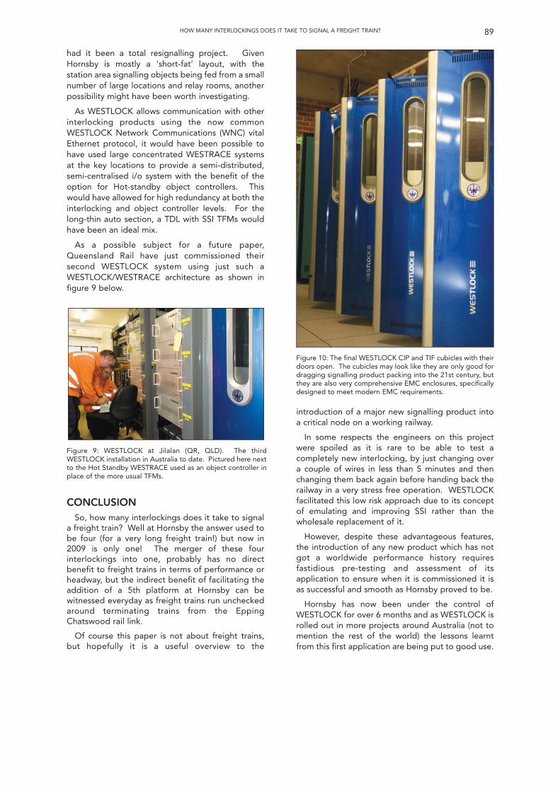
had it been a total resignalling project. GivenHornsby is mostly a ‘short-fat’ layout, with thestation area signalling objects being fed from a smallnumber of large locations and relay rooms, anotherpossibility might have been worth investigating.
As WESTLOCK allows communication with otherinterlocking products using the now commonWESTLOCK Network Communications (WNC) vitalEthernet protocol, it would have been possible tohave used large concentrated WESTRACE systemsat the key locations to provide a semi-distributed,semi-centralised i/o system with the benefit of theoption for Hot-standby object controllers. Thiswould have allowed for high redundancy at both theinterlocking and object controller levels. For thelong-thin auto section, a TDL with SSI TFMs wouldhave been an ideal mix.
As a possible subject for a future paper,Queensland Rail have just commissioned theirsecond WESTLOCK system using just such aWESTLOCK/WESTRACE architecture as shown infigure 9 below.
introduction of a major new signalling product intoa critical node on a working railway.
In some respects the engineers on this projectwere spoiled as it is rare to be able to test acompletely new interlocking, by just changing overa couple of wires in less than 5 minutes and thenchanging them back again before handing back therailway in a very stress free operation. WESTLOCKfacilitated this low risk approach due to its conceptof emulating and improving SSI rather than thewholesale replacement of it.
However, despite these advantageous features,the introduction of any new product which has notgot a worldwide performance history requiresfastidious pre-testing and assessment of itsapplication to ensure when it is commissioned it isas successful and smooth as Hornsby proved to be.
Hornsby has now been under the control ofWESTLOCK for over 6 months and as WESTLOCK isrolled out in more projects around Australia (not tomention the rest of the world) the lessons learntfrom this first application are being put to good use.
89HOW MANY INTERLOCKINGS DOES IT TAKE TO SIGNAL A FREIGHT TRAIN?
Figure 9: WESTLOCK at Jilalan (QR, QLD). The thirdWESTLOCK installation in Australia to date. Pictured here nextto the Hot Standby WESTRACE used as an object controller inplace of the more usual TFMs.
CONCLUSIONSo, how many interlockings does it take to signal
a freight train? Well at Hornsby the answer used tobe four (for a very long freight train!) but now in2009 is only one! The merger of these fourinterlockings into one, probably has no directbenefit to freight trains in terms of performance orheadway, but the indirect benefit of facilitating theaddition of a 5th platform at Hornsby can bewitnessed everyday as freight trains run uncheckedaround terminating trains from the EppingChatswood rail link.
Of course this paper is not about freight trains,but hopefully it is a useful overview to the
Figure 10: The final WESTLOCK CIP and TIF cubicles with theirdoors open. The cubicles may look like they are only good fordragging signalling product packing into the 21st century, butthey are also very comprehensive EMC enclosures, specificallydesigned to meet modern EMC requirements.
INTRODUCTIONIn this paper we look at what goal-based
standards can provide to the railway industry and ifgoal-based safety cases could be a valuable tool forreasoning about safety. We discuss opportunitiesand challenges for the development and use ofgoal-based safety cases. Finally we discuss thefuture of safety standards and investigate how thiscan become a reality in the railway industry.
The structure of the paper is outlined as follows.
1.Why we need goal-based standards
2.What goal-based standards exist
3.Generic goal structures
4.Generic safety management goals
5.Generic safety development assurance goals
6.Generic sets of goals
7.The assurance evidence required
8.The impact on railway safety standards
BACKGROUNDThe term “Assurance” inherently means a positive
declaration intended to give confidence. It is asubjective determination of the strength of aninference. Safety assurance is the determination ofthe confidence that can be placed in the safety of asystem. Assurance is a property of an argument’sconclusion and is based upon:
• the likelihood that the claims are true (i.e. theassurance of the claims); and
• the extent to which the claims entail theconclusion.
Safety Assurance is therefore a qualitativestatement expressing the degree of confidencethat a safety claim is true. The overall assurance ofa system is equal to the assurance of the top-levelgoal.
A Safety Case is the primary means ofcommunicating the safety requirements, safetymanagement environment and argument forassurance of critical systems. More specifically asafety case is a documented body of evidence thatprovides a convincing and valid argument that asystem is adequately safe for a given applicationin a given environment.
Although safety cases are generally accepted,there are different ways of constructing an argumentand providing the assurance evidence. The threemain approaches can be characterised as shown inFigure 1.
• Assurance via a set of claims about the system’ssafety behaviour.
• The use of accepted industry “good” practicesand guidelines.
• An investigation of known potentialvulnerabilities of the system.
90
Australasian SectionTechnical Meeting
held in
Brisbane 26 March 2010
Moving Towards Goal-BasedSafety Management
Dr Holder M Becht Phd BInfTech(Hons)1
SUMMARYIn virtually all safety-critical industries the operators of systems have to demonstrate a systematic and thorough
consideration of safety. This is generally done through the application of safety standards as part of thedevelopment of safety critical systems.
Many safety assurance standards (like EN50126 [1], IEC 61508 [8], DEF (Aust) 5679) [6] are very prescriptive. Theyrequire specific techniques, approaches or measures to be applied to achieve the safety objective without allowingthe users to select a suite of techniques and measures best suited for their application and developmentenvironment. The application of prescriptive techniques can work well for some systems but can be a hindrance forothers.
There has therefore been an increasing trend in many industries to demonstrate safety by assuring certain goalshave been achieved, rather than simply following prescriptive standards.
Goal-based standards do not specify the means of achieving compliance but sets goals that allow for alternativeways of achieving compliance. Goal-based safety standards are now a reality and applied in the medical industryand defence; examples of such standards are the UK Defence Standard 00-56 [5], and the UK Railway SafetyStandard The Yellow Book [11]
1 The author is a Safety & RAM Manager with Ansaldo STS.
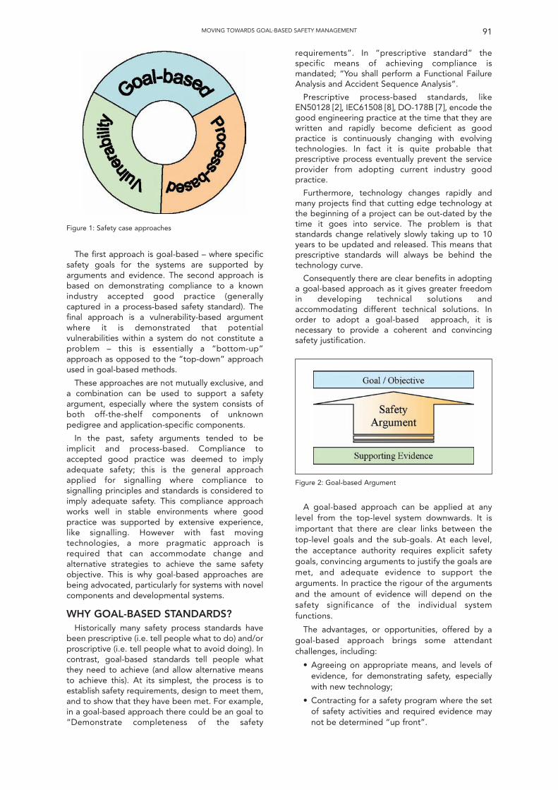
91MOVING TOWARDS GOAL-BASED SAFETY MANAGEMENT
Figure 1: Safety case approaches
The first approach is goal-based – where specificsafety goals for the systems are supported byarguments and evidence. The second approach isbased on demonstrating compliance to a knownindustry accepted good practice (generallycaptured in a process-based safety standard). Thefinal approach is a vulnerability-based argumentwhere it is demonstrated that potentialvulnerabilities within a system do not constitute aproblem – this is essentially a “bottom-up”approach as opposed to the “top-down” approachused in goal-based methods.
These approaches are not mutually exclusive, anda combination can be used to support a safetyargument, especially where the system consists ofboth off-the-shelf components of unknownpedigree and application-specific components.
In the past, safety arguments tended to beimplicit and process-based. Compliance toaccepted good practice was deemed to implyadequate safety; this is the general approachapplied for signalling where compliance tosignalling principles and standards is considered toimply adequate safety. This compliance approachworks well in stable environments where goodpractice was supported by extensive experience,like signalling. However with fast movingtechnologies, a more pragmatic approach isrequired that can accommodate change andalternative strategies to achieve the same safetyobjective. This is why goal-based approaches arebeing advocated, particularly for systems with novelcomponents and developmental systems.
WHY GOAL-BASED STANDARDS?Historically many safety process standards have
been prescriptive (i.e. tell people what to do) and/orproscriptive (i.e. tell people what to avoid doing). Incontrast, goal-based standards tell people whatthey need to achieve (and allow alternative meansto achieve this). At its simplest, the process is toestablish safety requirements, design to meet them,and to show that they have been met. For example,in a goal-based approach there could be an goal to“Demonstrate completeness of the safety
requirements”. In “prescriptive standard” thespecific means of achieving compliance ismandated; “You shall perform a Functional FailureAnalysis and Accident Sequence Analysis”.
Prescriptive process-based standards, likeEN50128 [2], IEC61508 [8], DO-178B [7], encode thegood engineering practice at the time that they arewritten and rapidly become deficient as goodpractice is continuously changing with evolvingtechnologies. In fact it is quite probable thatprescriptive process eventually prevent the serviceprovider from adopting current industry goodpractice.
Furthermore, technology changes rapidly andmany projects find that cutting edge technology atthe beginning of a project can be out-dated by thetime it goes into service. The problem is thatstandards change relatively slowly taking up to 10years to be updated and released. This means thatprescriptive standards will always be behind thetechnology curve.
Consequently there are clear benefits in adoptinga goal-based approach as it gives greater freedomin developing technical solutions andaccommodating different technical solutions. Inorder to adopt a goal-based approach, it isnecessary to provide a coherent and convincingsafety justification.
Figure 2: Goal-based Argument
A goal-based approach can be applied at anylevel from the top-level system downwards. It isimportant that there are clear links between thetop-level goals and the sub-goals. At each level,the acceptance authority requires explicit safetygoals, convincing arguments to justify the goals aremet, and adequate evidence to support thearguments. In practice the rigour of the argumentsand the amount of evidence will depend on thesafety significance of the individual systemfunctions.
The advantages, or opportunities, offered by agoal-based approach brings some attendantchallenges, including:
• Agreeing on appropriate means, and levels ofevidence, for demonstrating safety, especiallywith new technology;
• Contracting for a safety program where the setof safety activities and required evidence maynot be determined “up front”.
GENERIC GOAL STRUCTURESAlthough several standards have adopted goal-
based approaches to safety assurance, there aredifferences in the way the safety argument isconstructed and justified. The Goal StructuringNotation (GSN) is emerging as one of the preferredmethods for constructing a goal-based argument,and is defined in Def Stan 00-56 [5] and The YellowBook [11].
92 MOVING TOWARDS GOAL-BASED SAFETY MANAGEMENT
It may also be difficult for certifying bodies tocertify products to a goal-based standard. Withprescriptive standards this is a relative mechanicalprocess. The certifier would certify a product byusing the prescriptive requirements in that standardas a checklist to confirm compliance. With goal-based standards this will no longer be possible andthere is much more responsibility placed on thecertifier who will need to make a subjectivejudgement instead of an objective one. Certifiers inturn will most likely shift this responsibility onto theIndependent Safety Assessor to make thejudgement that a specific product or system is safe.
This means that in order for a goal-based standardto be effective some of the inherent subjectivity ofthis approach needs to be reduced to simplify theacceptance and certification process.
GOAL-BASED STANDARDSDespite the differences in detail, goal-based
approaches are now being adopted in standardswith the key premise that they are not to betechnology specific.
The UK Civil Aviation Authority software safetyassurance standard [12] identifies a standard set oftop-level goals for software based systems whichare generic (e.g. specification is valid, specificationis correctly implemented, etc.).
The software part of Def Stan 00-56 [5] requiresgoal-based safety justification and explicit safetyarguments to support the safety claims made. DefStan 00-56 [5] may have taken the goal-basedapproach too far in an attempt to be completelyflexible. The standard places all the onus on theservice provider to develop the system as theyplease and provide justification that the system issafe. It is clear from this standard, that somestructure and minimal processes need to beprescribed. In reality we see both approachesworking in parallel. The Yellow Book is one of thefew standards that provides high level goals andsuggests several process-based standards toachieve each goal.
As stated, a combination of somewhat prescriptivesafety management activities, generic goals, andprocess-based guidance must be captured in a goal-based standard for it to be effective and to allow awide range of technologies to be certified. Morespecifically, it must be recognised that theprescriptive process-based standards are primarily ahindrance for the development and assurance ofsoftware. It is this aspect of safety engineering thatneeds to be, and that will gain the most benefit from,a goal-based approach. The Safety Managementapproach is expected to remain fairly prescriptive,structured and consistent in future safety standards.In fact it is already fairly consistent across safetystandards from different countries and industries.The objectives and goal of safety management isinvestigated in more detail in a subsequent sectionbut before this is done, we depict the generic top-level goals that would be applicable to mostdevelopment projects and that should be reflectedin a goal-based standard.
Figure 3: Elements of Goal Structured Notation
The GSN is a graphical notation that explicitlyrepresents the individual elements of a safetyargument (requirements, claims, evidence andcontext) and, perhaps more significantly, therelationships that exist between these elements.That is, the GSN depicts how individualrequirements are supported by specific claims, howclaims are supported by evidence, and the assumedcontext that is defined for the argument. Theprincipal symbols of the notation are shown inFigure 3.
Figure 4 provides an example of a goal structureof safety arguments, which is generally applicable tomost applications.
GENERIC SAFETY MANAGEMENTGOALS
As detailed above, the safety managementapproach is expected to remain consistent amongststandards. This section will expand goal G7 ofFigure 4 to define the safety management goals thatwould enable the other goals to be achieved byensuring that safety activities are planned,monitored against the plan, and effectivelyexecuted.
Research and practical experience in safety-relatedsystems and careful study of existing safetystandards (e.g. Def Stan 00-56 [5], The Yellow Book[11], IEC 61508 [8], MIL-STD-882C [4], and Def(Aust)5679 [6]) have identified the following keyrequirements for the development of safety systems.
• It is essential to have a systematic approach tosafety that incorporates techniques which arevalid for hardware, operators and software.
• System design must be inherently safe; issuesraised during hazard analyses must be allowedto impact system design if necessary.
• The use of integrity levels allows the applicationof effort and rigor which is appropriate to thecriticality of a component. A practicable and
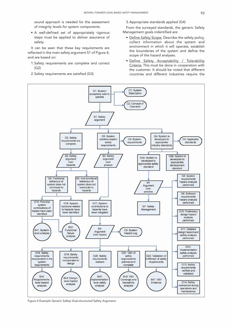
sound approach is needed for the assessmentof integrity levels for system components.
• A well-defined set of appropriately rigoroussteps must be applied to deliver assurance ofsafety.
It can be seen that these key requirements arereflected in the main safety argument S1 of Figure 4,and are based on:
1.Safety requirements are complete and correct(G2)
2.Safety requirements are satisfied (G3)
3.Appropriate standards applied (G4)
From the surveyed standards, the generic SafetyManagement goals indentified are:
• Define Safety Scope: Describe the safety policy,collect information about the system andenvironment in which it will operate, establishthe boundaries of the system and define thescope of the hazard analyses.
• Define Safety Acceptability / TolerabilityCriteria: This must be done in cooperation withthe customer. It should be noted that differentcountries and different industries require the
93MOVING TOWARDS GOAL-BASED SAFETY MANAGEMENT
Figure 4 Example Generic Safety Goal-structured Safety Argument.
risk scale to be adaptable to suit the particularsystem implementation depending on theoperational profile of the relevant system.
• Define Safety Organization: Establish andmaintain a safety organisation structure for theproject, including specifying roles and duties ofpersonnel and groups, providing reportingchannels, and ensuring adequate levels ofmanagerial and technical skills andindependence.
• Define Interface to Other Disciplines: Define theinteractions and data/information flow to andfrom other safety disciplines and other systemengineering disciplines to ensure theyeffectively work together and do not duplicatework.
• Define Hazard Tracking System: Define a singleclosed-loop hazard tracking system todocument hazards from identification toclosure, detailing the risk assessment, riskreduction and verification evidence.
• Establish Safety Management Group: Set up asystem safety management group (also referredto as system safety working group and safetycommittee by the surveyed standards) tooversee, review and endorse safetymanagement and engineering activities.
• Define Safety Development Assurance Tasks:Define the process for demonstrating allocatedintegrity / assurance levels of components.
• Define System Safety Management Plan:Describe the activities for achieving functionalsafety, plan the safety analyses andassessments, and describe the means todevelop and maintain the Safety Case.
• Independent Safety Assessment: Plan for andassign an independent organisation to provideassurance that relevant legislations, standardsand policies are complied with.
• Define Safety Management System: Provide athrough life safety management plan to manageand maintain the system Safety Case duringmaintenance and modifications untildecommissioning and disposal of the system.
As mentioned above, it is expected that thisaspect of safety management will remain relativelyprescriptive and consistent amongst standards,including those for railway signalling. The mainreason why this can be more prescriptive is becauseit is not technology specific.
The key benefit of the goal-based approach willhowever be more evident and obvious for thedevelopment assurance of software and, to a lesserextent, hardware which are technology dependent.
SAFETY DEVELOPMENT ASSURANCEThe primary objective of development assurance
is to provide confidence that the system is free fromsystematic faults. The second objective is todemonstrate that the safety requirements havebeen correctly implemented. Developmentassurance is required for the development of
software, hardware and configuration data, likeapplication logic for a signalling interlocking.
Functional safety requirements (generally) requirethe performance of certain functions to provide alevel of hazard mitigation and risk reduction. Thesafety integrity (also referred to as DevelopmentAssurance Level) requirements define theseperformance requirements, which are directlyproportional to the level of risk reduction requiredand claimed. The higher the level of risk reduction,the higher the level of integrity and confidencerequired that the component is functioningcorrectly.
Integrity requirements define the reliability androbustness required for the given safetyrequirements and can also be used to define theavailability of the system to perform its functions.
Standards that use Safety Integrity Levels (e.g. IEC61508 [8]), or their equivalent concepts(Development Assurance Levels in SAE ARP 4761[10] or Safety Assurance Levels in DEF (Aust) 5679),[6] explicitly or implicitly define good practice foreach of the levels and therefore implicitly linkengineering methods and tools with risk andquantitative or pseudo-quantitative requirements.By dictating methods, a strategy for achieving therequisite confidence is imposed, which may workwell for some applications but be a hindrance inothers as already discussed.
Development assurance is an area where a goal-based standard can and needs to provide flexibilityto allow service providers to select the mostappropriate set of techniques and practices for thesystem under development. We cannot get awayfrom applying a set of techniques and measures todevelop software and hardware. Furthermore unlessthe techniques and measures applied areconsidered to be industry good practice, it will bedifficult to justify in the safety argument.
The Yellow Book provides the service providersome flexibility when it comes to developmentassurance by providing a list of prescriptive processstandards (e.g. EN50128 [2], IEC 61508 [8]) that maybe applied. What is required is to allow for theservice provider to select, mix and match,techniques and measures from various developmentstandards, or wherever current industry goodpractice is defined. This is easier said than done.That is, for this to be effective, there needs to be alink between development assurance goals anddevelopment processes defined within thestandards.
The software assurance parts of developmentassurance standards, like EN50128 [2], IEC 61508[8], DO-178B [7], DO-278 [9], Def(Aust) 5679 [6],SAE ARP 4761 [10], need to be goal-based. Theyneed to provide a tailorable safety developmentprocess framework that details the type ofassurance that must be provided (i.e. the goals). Thederivation of the framework must focus on safedesign concepts (i.e. goal-based) instead of gooddesign practices (i.e. process-based), as designpractices are generally tuned towards reliability andquality instead of safety [13].
94 MOVING TOWARDS GOAL-BASED SAFETY MANAGEMENT
In addition, these standards need to providesufficient guidance for alternative techniques andmeasures that can be selected in order to achievethese goals for the required integrity. This means alink needs to be provided between goals anddevelopment processes to make it easier for serviceproviders to justify that a selected set of processesmeets the development goal.
For example, when considering software safetydevelopment assurance, the good-practicetechniques and measures mandated and/orsuggested in the surveyed standards can becategorised into four objectives or goals:
• Providing a good design basis for development,customized for safety; expressed as a designand coding standard including selection of asuitable programming language or a safesubset of the programming language.
• Ensuring that safety requirements are correctand complete; by the application of structuredhazard and risk analyses.
• Ensuring that safety requirements areadequately addressed in the design, and thatthe code implements only the allocated andderived requirements; by the provision oftraceability and coverage.
• Providing evidence that each softwarecomponent meets its allocated safetyrequirements; by the provision of design andcoding verification & validation.
The key generic goals for the development ofhardware would be very similar and cover:
• Quality and Reliability Assurance ofComponents.
• Completeness of safety requirements.
• Requirements traceability and coverage.
• Design and manufacturing verification andvalidation.
The other important aspect to remember is thatdevelopment goals need to focus on safety and notjust quality and reliability to ensure that the end-product is safe [13].
It is believed that defining generic sets ofdevelopment goals, particularly for software, asdetailed above, is what standards bodies need tofocus on in order for the goal-based approach to beeffective. Generic sets of development goals willmost likely need to be defined and fine-tuned fordifferent industries and different types ofapplication to make it easier for the service providerto determine what evidence is required and easierto convince the acceptance authority. This will notbe an easy activity and much effort and expertise isrequired to get this right.
THE ASSURANCE EVIDENCEThe main problem and the question always asked
with the goal-based approach, as mentioned severaltimes, is “What evidence is needed and how muchevidence is enough?” Unfortunately there is nodefinitive answer to this question. Much effort isrequired by the service provider to define what
evidence will be provided and then convince theacceptance authority. The reason that there is nodefinitive answer is intrinsic to the goal-basedapproach in that the evidence required isapplication specific and specific to the selectedmethod of development. What is clearer is that theamount of evidence required is proportional to thelevel of integrity required or associated with theproduct.
Having generic sets of development goalsdefined, as detailed above, will help by providing amore structured breakdown of the type of evidencerequired. The service provider needs to break eachgoal down into manageable sub-goals which in turnmake it easier to identify what evidence wouldsupport an argument to justify each sub-goal.
Def Stan 00-56 [5] discusses the need for threetypes of evidence, and requires that a combinationof these need to be provided to justify the overallsafety argument; these are: process-based, product-based, and counter evidence based on vulnerabilitystudies. It should be noted that these actually reflectthe three approaches described in Figure 1, and arealso evident in the generic goal structure shown inFigure 4.
Process-based evidence needs to provideconfidence that industry “good” practice wasapplied for system development and safetymanagement. Generally, product-based evidence isconsidered to be an output or result of following aparticular process. Subsequently having thedevelopment processes identified should guide theservice provider in identifying the type of product-based evidence that is required for the systemunder development.
It is important to understand the purpose of theevidence, and what it will be used for. The evidencewill be to support arguments about the behaviour ofa system to gain confidence that the system is safe.The independent safety assessor will assess eachpiece of evidence subjectively against eachargument by considering:
• Relevance
• Sufficiency
• Argument coverage
• Validity
• Independence
As already mentioned, the intrinsic subjectivity ofthe goal-based approach is the main drawback withthis approach. This is why well-defined sets ofgeneric development goals and a consistent safetymanagement approach is so important for reducingsome of the subjectivity.
Evidence needs to be placed under configurationmanagement and associated with the systemconfiguration that it allies to. Quality attributes thatare associated with most engineering artefacts arelikewise applicable to evidence. It must be possibleto demonstrate the following properties for eachpiece of evidence.
• Existence
• Precision
95MOVING TOWARDS GOAL-BASED SAFETY MANAGEMENT
• Completeness
• Correctness
These will be assessed objectively by the safetyassessor.
RAILWAY SAFETY STANDARDS IMPACTSo what does this mean for the railway industry
and the well known standards (i.e. CENELEC [1][2][3]and The Yellow Book [11]) that regulate and governit?
The CENELEC standards EN5012x are well knownand widely accepted in the railway industry acrossthe globe, including Australia, Europe, Asia andAfrica. The main problem with regard to thesestandards is that they are closely linked andinterleaved.
This does not necessarily mean that this would bethe end of the CENELEC standards. In fact,EN50126 [1] and EN50129 [3] would not requiremuch change, as they are not technology specificand define a relatively generic safety lifecycle andacceptance framework, along the lines of thegeneric safety argument in Figure 4. One importantchange would be the decoupling between thesestandards, e.g. EN50129 should not prescribe theuse of EN50126 [1].
EN50129 [3] would require Safety Cases to begoal-based and require the evidence to be againstthe behaviour of the system instead of focusing oncompliance against the requirements of EN5012x.
The biggest impact would be for EN50128 [2],which will need to change to goal based, asdiscussed above, and focus on safe designconcepts, covering:
• Design and coding standard.
• Application of structured hazard and riskanalyses.
• Safety requirements traceability and coverage.
• Design and coding verification & validation.
The Yellow Book [11] is most likely going tobecome the standard of choice in the railwayindustry and is already being preferred or adoptedby many acceptance authorities in the UK andAustralia. The Yellow Book [11] is already goal-based and includes the goal structured notation.The Yellow Book [11] will need to allow for flexibilityfor the selection of development processes andshould define generic sets of development goals,instead of listing prescriptive standards that shouldbe applied.
From a railway signalling perspective, someacceptance authorities (e.g. RailCorp, TIDC) arealready requiring service providers to provide moreassurance evidence and not just show compliance tosignalling standards and principles. Even withoutthe use of goal-based standards, there will be muchmore effort required by the acceptance authoritiesin the future to justify a signalling design,particularly justification of the application logic of aninterlocking. However goal-based standards willallow service providers to develop the applicationlogic using techniques that best suit their needs.
CONCLUSIONSIt should be clear at this stage that prescriptive
standards hampers the continual move forward intechnology, while the goal-based approach leavesus without suitable advice or agreement onachieving assurance.
A goal-based approach, along the lines of thatused in Def Stan 00-56 and The Yellow Book [11],has obvious benefits as it imposes fewer constraintson the implementation, both in terms of processesand in technical solutions. The goal-based approachis useful from a safety assurance perspective, as thequestions focus on safety-related outcomes (e.g.“what evidence do you have to show that displayupdates occur within x seconds?).
In a goal-based approach, it is not sufficient todemonstrate compliance to a generic safety process(such as IEC 61508 [8]). Convincing arguments haveto be constructed that relate to the behaviour of thespecific product and its safety properties and thiscan be difficult for service providers to adopt. Thereis a need to shift from documenting how hardpeople have tried to develop a system, to providingevidence and arguments about the behaviour ofthat system.
However, it has to be recognised that such anapproach represents a significant shift from:
• a process compliance approach to a productorientated, safety property approach
• a tick-box mentality to argument-based mind-set
The future of safety management is and needs tobe goal-based as prescriptive standards cannotkeep up with fast changing technology. For a goal-based approach to be effective and efficient:
• The goals need to not be technologicallyspecific and focus on safe design concepts.
• There needs to be a well-defined (somewhatprescriptive) and structured process for safetymanagement, as detailed in Figure 4.
• Development assurance processes, particularlyfor software, need to be tailorable and flexible,with a clear link to goals.
• A rich collection of generic sets of developmentgoals needs to be defined and captured instandards.
• Guidance needs to be provided for defining thegoals and indentifying (and gaining agreementwith the acceptance authority) on the type andamount of evidence required.
This shift towards goal-based standards will by nomeans be easy and it will most likely take some timeto get things right. A quite a mature industry withlots of experts is required, with the UK leading theway, particularly to develop the generic sets of goalsfor each industry.
The main challenge with the goal-based approachwill be for the service provider and acceptanceauthority to agree on the goals and requiredevidence. It is also not clear if the goal-basedapproach would actually make it easier or more
96 MOVING TOWARDS GOAL-BASED SAFETY MANAGEMENT
difficult for cross standard acceptance andcertification, because of the more subjective natureof the goal-based approach.
REFERENCES1. CENELEC EN 50126. Railway applications -
The specification and demonstration ofReliability, Availability, Maintainability andSafety (RAMS). 1999.
2. CENELEC EN 50128. Railway applications -Communications, signalling and processingsystems - Software for railway control andprotection systems. 2001.
3. CENELEC EN 50129. Railway applications -Communication, signalling and processingsystems - Safety related electronic systemsfor signalling. 2003.
4. MIL-STD-882C: System Safety ProgramRequirements. United States of AmericaDepartment of Defense. 1996.
5. Def Stan 00-56: Safety Management ofDefence Systems. United Kingdom Ministry ofDefence. 2007.
6. Def (Aust) 5679: The Procurement OfComputer-based Safety Critical Systems.Defence Science Technology Organisation(DSTO). 1998.
7. RTCA DO-178B: Software Considerations inAirborne Systems and Equipment
Certification. Radio Technical Commission forAeronautics (RTCA). 1992.
8. IEC 61508: Functional Safety: Safety RelatedSystems. International Electro-technicalCommission (IEC). 1995.
9. RTCA DO-278: Guidelines forCommunications, Navigation, Surveillance,and Air Traffic Management. Radio TechnicalCommission for Aeronautics (RTCA). 2002
10. SAE ARP 4761: Guidelines and Methods forConducting the Safety Assessment Processon Civil Airborne Systems and Equipments.Society of Automotive Engineers. 1996.
11. The Yellow Book: Engineering SafetyManagement, Volumes 1 and 2,Fundamentals and Guidance. Rail Safety andStandards Board. Issue 4, 2007.
12. CAA SW01: Regulatory Objective forSoftware in Safety Related Air Traffic Services.Civil Aviation Authority, Safety RegulationGroup, Air Traffic Services SafetyRequirement, Document CAP 670, SectionSW01: 2002.
13. J.A. McDermid, Software Safety: Where’s theEvidence?. 6th Australian Workshop onIndustrial Experience with Safety CriticalSystems and Software (SCS’01), 2001.
97MOVING TOWARDS GOAL-BASED SAFETY MANAGEMENT
1 WHAT IS SIX SIGMA?Six Sigma is process based and data driven. It is a
disciplined way to improve an organisationalculture, and to drive an improvement in anorganisation to meet an important need. It is a wayof driving Improvement, speed and excellence.
There are plenty of other texts and resourcesavailable which can tell you all about it in moredetail.
The term Six Sigma was initiated by Motorola todescribe a process, which used a number of qualitytools with statistical analysis to improve a businessprocess, or a manufacturing process. The aim is toimprove product quality, performance, andreliability or to minimise it’s cost.
The Six Sigma symbol or notation is
The sigma is the Greek symbol used to describestandard deviation. Six Sigma refers to six standarddeviations from the mean when referred to astandard distribution.
1.1 SIX SIGMA APPLICATIONS
Six Sigma can be used and adapted to suit theneed:
• Tool to eliminate variation
• Vision of product & service excellence
• Value to our customers
• Business Improvement tool of choice for WorldClass Companies
There are a lot successful companies in Australia andoverseas using Six Sigma. A number of railorganisations and rail companies (here & overseas)have or are applying Six Sigma to improve theirbusinesses.
1.2 BASIC SIX SIGMA CONCEPTS
• All processes have variability
• Variability has definable causes
• Typically only a few causes are significant
• If causes can be identified and understood, theycan be controlled
• Data, rather than assumptions, is held as truthand drives decision making
Six Sigma can be applied to many processes notjust Engineering and Manufacturing such as-Financial, Human Resources, etc.
Reducing Variability Is the Essence of Six Sigma
1.3 SOME SIX SIGMA THOUGHTS
• If you can’t measure the business ….. you can’tfix it
• The data is not always there in front of yournose, and it’s not always perfect or in the formthat you want it
• Everything you do is a process….Processbehaviour always determines what you and yourcustomer get!
• All the information needed to improve aprocess resides in the data, and within theexperience of the people working the processes
• Six Sigma is all about applying statistical toolsto raw data to provide leaders with informationthat improves processes in practical ways
• Six Sigma process improvement rarely finds thesilver bullet. Incremental change most oftenyields the results needed
98
Australasian SectionTechnical Meeting
held in
Brisbane 26 March 2010
Using Six Sigma to Improve Track CircuitReliability
Peter McGregor BEng(Elect) Grad Dip (Systems) MIRSE1
EXECUTIVE SUMMARYIs Six Sigma just another management fad? Is it just another business opportunity for the consultancy industry?
Yes, it could be if you let it. For RailCorp our Six Sigma journey has commenced with an initial number of projectsin the Asset Management group focusing on reliability improvements which were being sought by theorganisation.
In the first part of the paper I give a brief introduction to Six Sigma and what it is. I than go onto describe howwe commenced using Six Sigma and how it was applied to our reliability improvement projects. In the third partof the paper I describe in more detail a project where we used some of the Six Sigma tools and methodology toimprove the reliability of FS2500 jointless track circuits in a critical area of the RailCorp network and how using asimple clip on ferrite solved a problem with Receiver (RX) lockup.
1 The author is A/Head of Signalling Design – Professional ServicesDivision RailCorp.
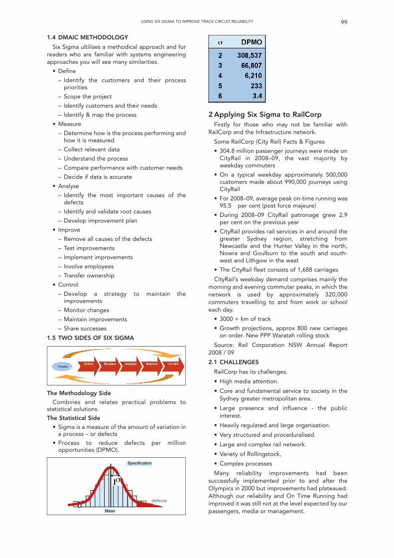
1.4 DMAIC METHODOLOGY
Six Sigma ultilises a methodical approach and forreaders who are familiar with systems engineeringapproaches you will see many similarities.
• Define
– Identify the customers and their processpriorities
– Scope the project
– Identify customers and their needs
– Identify & map the process
• Measure
– Determine how is the process performing andhow it is measured
– Collect relevant data
– Understand the process
– Compare performance with customer needs
– Decide if data is accurate
• Analyse
– Identify the most important causes of thedefects
– Identify and validate root causes
– Develop improvement plan
• Improve
– Remove all causes of the defects
– Test improvements
– Implement improvements
– Involve employees
– Transfer ownership
• Control
– Develop a strategy to maintain theimprovements
– Monitor changes
– Maintain improvements
– Share successes
1.5 TWO SIDES OF SIX SIGMA
2 Applying Six Sigma to RailCorpFirstly for those who may not be familiar with
RailCorp and the Infrastructure network.
Some RailCorp (City Rail) Facts & Figures
• 304.8 million passenger journeys were made onCityRail in 2008–09, the vast majority byweekday commuters
• On a typical weekday approximately 500,000customers made about 990,000 journeys usingCityRail
• For 2008–09, average peak on-time running was95.5 per cent (post force majeure)
• During 2008–09 CityRail patronage grew 2.9per cent on the previous year
• CityRail provides rail services in and around thegreater Sydney region, stretching fromNewcastle and the Hunter Valley in the north,Nowra and Goulburn to the south and south-west and Lithgow in the west
• The CityRail fleet consists of 1,688 carriages
CityRail’s weekday demand comprises mainly themorning and evening commuter peaks, in which thenetwork is used by approximately 320,000commuters travelling to and from work or schooleach day.
• 3000 + km of track
• Growth projections, approx 800 new carriageson order. New PPP Waratah rolling stock
Source: Rail Corporation NSW Annual Report2008 / 09
2.1 CHALLENGES
RailCorp has its challenges.
• High media attention.
• Core and fundamental service to society in theSydney greater metropolitan area.
• Large presence and influence - the publicinterest.
• Heavily regulated and large organisation.
• Very structured and proceduralised.
• Large and complex rail network.
• Variety of Rollingstock,
• Complex processes
Many reliability improvements had beensuccessfully implemented prior to and after theOlympics in 2000 but improvements had plateaued.Although our reliability and On Time Running hadimproved it was still not at the level expected by ourpassengers, media or management.
99USING SIX SIGMA TO IMPROVE TRACK CIRCUIT RELIABILITY
The Methodology Side
Combines and relates practical problems tostatistical solutions.
The Statistical Side
• Sigma is a measure of the amount of variation ina process – or defects
• Process to reduce defects per millionopportunities (DPMO).
Prepare
Specification
Mean
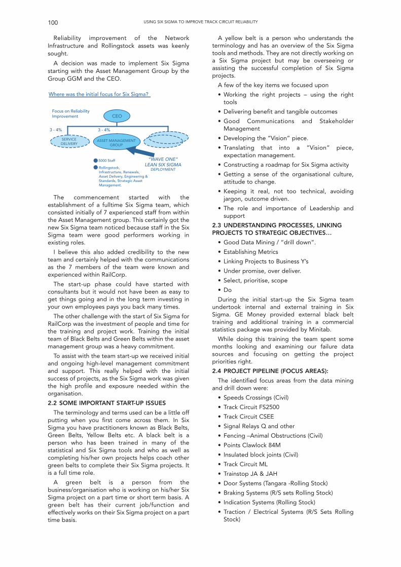
Reliability improvement of the NetworkInfrastructure and Rollingstock assets was keenlysought.
A decision was made to implement Six Sigmastarting with the Asset Management Group by theGroup GGM and the CEO.
A yellow belt is a person who understands theterminology and has an overview of the Six Sigmatools and methods. They are not directly working ona Six Sigma project but may be overseeing orassisting the successful completion of Six Sigmaprojects.
A few of the key items we focused upon
• Working the right projects – using the righttools
• Delivering benefit and tangible outcomes
• Good Communications and StakeholderManagement
• Developing the “Vision” piece.
• Translating that into a “Vision” piece,expectation management.
• Constructing a roadmap for Six Sigma activity
• Getting a sense of the organisational culture,attitude to change.
• Keeping it real, not too technical, avoidingjargon, outcome driven.
• The role and importance of Leadership andsupport
2.3 UNDERSTANDING PROCESSES, LINKINGPROJECTS TO STRATEGIC OBJECTIVES…
• Good Data Mining / “drill down”.
• Establishing Metrics
• Linking Projects to Business Y’s
• Under promise, over deliver.
• Select, prioritise, scope
• Do
During the initial start-up the Six Sigma teamundertook internal and external training in SixSigma. GE Money provided external black belttraining and additional training in a commercialstatistics package was provided by Minitab.
While doing this training the team spent somemonths looking and examining our failure datasources and focusing on getting the projectpriorities right.
2.4 PROJECT PIPELINE (FOCUS AREAS):
The identified focus areas from the data miningand drill down were:
• Speeds Crossings (Civil)
• Track Circuit FS2500
• Track Circuit CSEE
• Signal Relays Q and other
• Fencing –Animal Obstructions (Civil)
• Points Clawlock 84M
• Insulated block joints (Civil)
• Track Circuit ML
• Trainstop JA & JAH
• Door Systems (Tangara -Rolling Stock)
• Braking Systems (R/S sets Rolling Stock)
• Indication Systems (Rolling Stock)
• Traction / Electrical Systems (R/S Sets RollingStock)
100 USING SIX SIGMA TO IMPROVE TRACK CIRCUIT RELIABILITY
• •
“WA
The commencement started with theestablishment of a fulltime Six Sigma team, whichconsisted initially of 7 experienced staff from withinthe Asset Management group. This certainly got thenew Six Sigma team noticed because staff in the SixSigma team were good performers working inexisting roles.
I believe this also added credibility to the newteam and certainly helped with the communicationsas the 7 members of the team were known andexperienced within RailCorp.
The start-up phase could have started withconsultants but it would not have been as easy toget things going and in the long term investing inyour own employees pays you back many times.
The other challenge with the start of Six Sigma forRailCorp was the investment of people and time forthe training and project work. Training the initialteam of Black Belts and Green Belts within the assetmanagement group was a heavy commitment.
To assist with the team start-up we received initialand ongoing high-level management commitmentand support. This really helped with the initialsuccess of projects, as the Six Sigma work was giventhe high profile and exposure needed within theorganisation.
2.2 SOME IMPORTANT START-UP ISSUES
The terminology and terms used can be a little offputting when you first come across them. In SixSigma you have practitioners known as Black Belts,Green Belts, Yellow Belts etc. A black belt is aperson who has been trained in many of thestatistical and Six Sigma tools and who as well ascompleting his/her own projects helps coach othergreen belts to complete their Six Sigma projects. Itis a full time role.
A green belt is a person from thebusiness/organisation who is working on his/her SixSigma project on a part time or short term basis. Agreen belt has their current job/function andeffectively works on their Six Sigma project on a parttime basis.
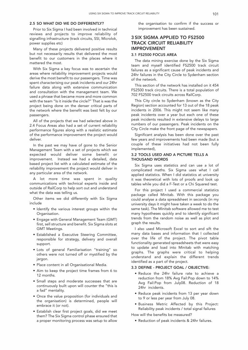
2.5 SO WHAT DID WE DO DIFFERENTLY?
Prior to Six Sigma I had been involved in technicalreviews and projects to improve reliability ofsignalling infrastructure (track circuits, SSI, Microlok,power supplies etc)
Many of these projects delivered positive resultsbut not necessarily results that delivered the mostbenefit to our customers in the places where itmattered the most.
With Six Sigma a key focus was to ascertain theareas where reliability improvement projects wouldderive the most benefit to our passengers. Time wasspent characterising our peak incidents and our 24hrfailure data along with extensive communicationand consultation with the management team. Weused a phrase that became more and more commonwith the team “Is it inside the circle?” That is was theproject being done on the denser critical parts ofthe network where the benefit was best felt by ourpassengers.
All of the projects that we had selected above in2.4 Focus Areas also had a set of current reliabilityperformance figures along with a realistic estimateof the performance improvement the project woulddeliver.
In the past we may have of gone to the SeniorManagement Team with a set of projects which weexpected would deliver some benefit orimprovement. Instead we had a detailed, databased project list with a calculated estimate of thereliability improvement the project would deliver inany particular area of the network.
A lot more time was spent in qualitycommunications with technical experts inside andoutside of RailCorp to help sort out and understandwhat the data was telling us.
Other items we did differently with Six Sigmainclude
• Identify the various interest groups within theOrganisation.
• Engage with General Management Team (GMT)first, sell structure and benefit. Six Sigma slots atGMT Meetings.
• Established a Executive Steering Committee,responsible for strategy, delivery and overallsupport.
• Lots of general Familiarisation “training” soothers were not turned off or mystified by thejargon.
• Place content in all Organisational Media.
• Aim to keep the project time frames from 6 to12 months.
• Small steps and moderate successes that arecontinuously built upon will counter the “this isa fad” mentality.
• Once the value proposition (for individuals andthe organisation) is determined, people willembrace it (or not).
• Establish clear first project goals, did we meetthem? The Six Sigma control phase ensured thata proper monitoring process was setup to allow
the organisation to confirm if the success orimprovement has been sustained.
3 SIX SIGMA APPLIED TO FS2500TRACK CIRCUIT RELIABILITYIMPROVEMENT3.1 FS2500 FOCUS AREA
The data mining exercise done by the Six Sigmateam and myself identified FS2500 track circuitfailures as a significant cause of peak incidents and24hr failures in the City Circle to Sydenham sectionof the network.
This section of the network has installed on it 454FS2500 track circuits. There is a total population of702 FS2500 track circuits across RailCorp.
This City circle to Sydenham (known as the CityRegion) section accounted for 13 out of the 18 peakincidents in 2006. This might not seem like manypeak incidents over a year but each one of thesepeak incidents resulted in extensive delays to largenumbers of our passengers. Peak incidents on theCity Circle make the front page of the newspapers.
Significant analysis has been done over the pastfew years and improvements had been made (but acouple of these initiatives had not been fullyimplemented),
3.2 TOOLS USED AND A PICTURE TELLS ATHOUSAND WORDS
Six Sigma uses statistics and can use a lot ofcomplicated maths. Six Sigma uses what I callapplied statistics. When I did statistics at universityit was theoretical with lots of proofs and look uptables while you did a F-Test or a Chi Squared test.
For this project I used a commercial statisticspackage called Minitab. With this package youcould analyse a data spreadsheet in seconds (in myuniversity days it might have taken a week to do thesame task). The Minitab software allowed me to testmany hypotheses quickly and to identify significanttrends from the random noise as well as plot andgraph the results.
I also used Microsoft Excel to sort and sift themany data bases and information that I collectedover the life of the project. The pivot tablefunctionality generated spreadsheets that were easyto update and load into Minitab with matchinggraphs. The graphs were critical to helpingunderstand and explain the different trendsidentified as a part of the project.
3.3 DEFINE - PROJECT GOAL / OBJECTIVE:
• Reduce the 24hr failure rate to achieve areduction from 18% Avg Fail:Pop down to 14%Avg Fail:Pop from July08. Reduction of 1824hr incidents.
• Reduce peak incidents from 13 per year downto 9 or less per year from July 08.
• Business Metric Affected by this Project:Reliability peak incidents / total signal failures
How will the benefits be measured?
• Reduction of peak incidents & 24hr failures.
101USING SIX SIGMA TO IMPROVE TRACK CIRCUIT RELIABILITY
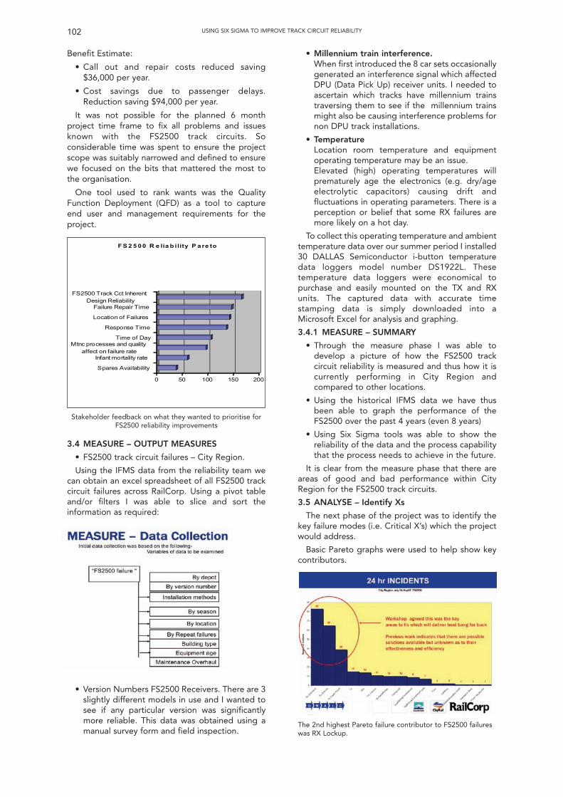
Benefit Estimate:
• Call out and repair costs reduced saving$36,000 per year.
• Cost savings due to passenger delays.Reduction saving $94,000 per year.
It was not possible for the planned 6 monthproject time frame to fix all problems and issuesknown with the FS2500 track circuits. Soconsiderable time was spent to ensure the projectscope was suitably narrowed and defined to ensurewe focused on the bits that mattered the most tothe organisation.
One tool used to rank wants was the QualityFunction Deployment (QFD) as a tool to captureend user and management requirements for theproject.
• Millennium train interference.When first introduced the 8 car sets occasionallygenerated an interference signal which affectedDPU (Data Pick Up) receiver units. I needed toascertain which tracks have millennium trainstraversing them to see if the millennium trainsmight also be causing interference problems fornon DPU track installations.
• TemperatureLocation room temperature and equipmentoperating temperature may be an issue.Elevated (high) operating temperatures willprematurely age the electronics (e.g. dry/ageelectrolytic capacitors) causing drift andfluctuations in operating parameters. There is aperception or belief that some RX failures aremore likely on a hot day.
To collect this operating temperature and ambienttemperature data over our summer period I installed30 DALLAS Semiconductor i-button temperaturedata loggers model number DS1922L. Thesetemperature data loggers were economical topurchase and easily mounted on the TX and RXunits. The captured data with accurate timestamping data is simply downloaded into aMicrosoft Excel for analysis and graphing.
3.4.1 MEASURE – SUMMARY
• Through the measure phase I was able todevelop a picture of how the FS2500 trackcircuit reliability is measured and thus how it iscurrently performing in City Region andcompared to other locations.
• Using the historical IFMS data we have thusbeen able to graph the performance of theFS2500 over the past 4 years (even 8 years)
• Using Six Sigma tools was able to show thereliability of the data and the process capabilitythat the process needs to achieve in the future.
It is clear from the measure phase that there areareas of good and bad performance within CityRegion for the FS2500 track circuits.
3.5 ANALYSE – Identify Xs
The next phase of the project was to identify thekey failure modes (i.e. Critical X’s) which the projectwould address.
Basic Pareto graphs were used to help show keycontributors.
102 USING SIX SIGMA TO IMPROVE TRACK CIRCUIT RELIABILITY
0 50 100 150 200
FS2500 Track Cct InherentDesign Reliability
Failure Repair Time
Location of Failures
Response Time
Time of DayMtnc processes and quality
affect on failure rateInfant mortality rate
Spares Availability
F S 2 5 0 0 R e lia b i lity P a re to
Stakeholder feedback on what they wanted to prioritise forFS2500 reliability improvements
3.4 MEASURE – OUTPUT MEASURES
• FS2500 track circuit failures – City Region.
Using the IFMS data from the reliability team wecan obtain an excel spreadsheet of all FS2500 trackcircuit failures across RailCorp. Using a pivot tableand/or filters I was able to slice and sort theinformation as required:
• Version Numbers FS2500 Receivers. There are 3slightly different models in use and I wanted tosee if any particular version was significantlymore reliable. This data was obtained using amanual survey form and field inspection.
The 2nd highest Pareto failure contributor to FS2500 failureswas RX Lockup.
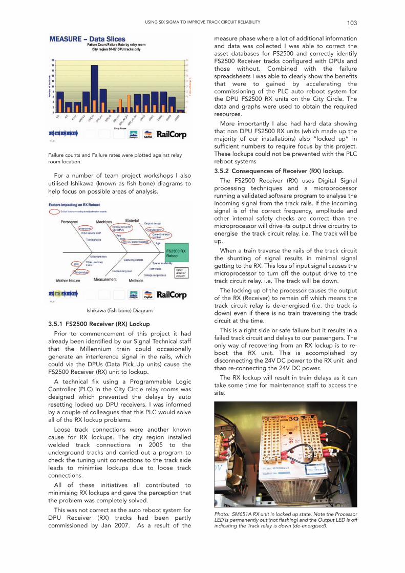
Failure counts and Failure rates were plotted against relayroom location.
For a number of team project workshops I alsoutilised Ishikawa (known as fish bone) diagrams tohelp focus on possible areas of analysis.
measure phase where a lot of additional informationand data was collected I was able to correct theasset databases for FS2500 and correctly identifyFS2500 Receiver tracks configured with DPUs andthose without. Combined with the failurespreadsheets I was able to clearly show the benefitsthat were to gained by accelerating thecommissioning of the PLC auto reboot system forthe DPU FS2500 RX units on the City Circle. Thedata and graphs were used to obtain the requiredresources.
More importantly I also had hard data showingthat non DPU FS2500 RX units (which made up themajority of our installations) also “locked up” insufficient numbers to require focus by this project.These lockups could not be prevented with the PLCreboot systems
3.5.2 Consequences of Receiver (RX) lockup.
The FS2500 Receiver (RX) uses Digital Signalprocessing techniques and a microprocessorrunning a validated software program to analyse theincoming signal from the track rails. If the incomingsignal is of the correct frequency, amplitude andother internal safety checks are correct than themicroprocessor will drive its output drive circuitry toenergise the track circuit relay. i.e. The track will beup.
When a train traverse the rails of the track circuitthe shunting of signal results in minimal signalgetting to the RX. This loss of input signal causes themicroprocessor to turn off the output drive to thetrack circuit relay. i.e. The track will be down.
The locking up of the processor causes the outputof the RX (Receiver) to remain off which means thetrack circuit relay is de-energised (i.e. the track isdown) even if there is no train traversing the trackcircuit at the time.
This is a right side or safe failure but it results in afailed track circuit and delays to our passengers. Theonly way of recovering from an RX lockup is to re-boot the RX unit. This is accomplished bydisconnecting the 24V DC power to the RX unit andthan re-connecting the 24V DC power.
The RX lockup will result in train delays as it cantake some time for maintenance staff to access thesite.
103USING SIX SIGMA TO IMPROVE TRACK CIRCUIT RELIABILITY
Ishikawa (fish bone) Diagram
3.5.1 FS2500 Receiver (RX) Lockup
Prior to commencement of this project it hadalready been identified by our Signal Technical staffthat the Millennium train could occasionallygenerate an interference signal in the rails, whichcould via the DPUs (Data Pick Up units) cause theFS2500 Receiver (RX) unit to lockup.
A technical fix using a Programmable LogicController (PLC) in the City Circle relay rooms wasdesigned which prevented the delays by autoresetting locked up DPU receivers. I was informedby a couple of colleagues that this PLC would solveall of the RX lockup problems.
Loose track connections were another knowncause for RX lockups. The city region installedwelded track connections in 2005 to theunderground tracks and carried out a program tocheck the tuning unit connections to the track sideleads to minimise lockups due to loose trackconnections.
All of these initiatives all contributed tominimising RX lockups and gave the perception thatthe problem was completely solved.
This was not correct as the auto reboot system forDPU Receiver (RX) tracks had been partlycommissioned by Jan 2007. As a result of the
Photo: SM651A RX unit in locked up state. Note the ProcessorLED is permanently out (not flashing) and the Output LED is offindicating the Track relay is down (de-energised).
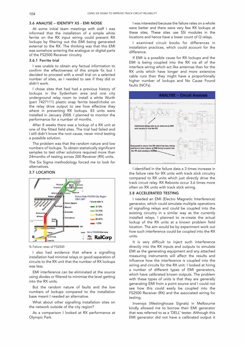
3.6 ANALYSE – IDENTIFY XS - EMI NOISE
At some initial team meetings with staff I wasinformed that the installation of a simple whiteferrite on the RX input wiring could prevent RXlockups by filtering out the EMI being generatedexternal to the RX. The thinking was that this EMIwas somehow entering the analogue or digital partsof the FS2500 Receiver circuitry
3.6.1 Ferrite trial
I was unable to obtain any factual information toconfirm the effectiveness of this simple fix but Idecided to proceed with a small trial on a selectednumber of sites, as I needed to see if they did ordidn’t work.
I chose sites that had had a previous history oflockups in the Sydenham area and one cityunderground relay room to install a white Wurth(part 7427111) plastic snap ferrite bead/choke onthe relay drive output to see how effective theywhere in preventing RX lockups. 83 units wereinstalled in January 2008. I planned to monitor theperformance for a number of months.
After 8 weeks there was a lockup of a RX unit atone of the fitted field sites. The trial had failed andI still didn’t know the root cause, never mind testinga possible solution.
The problem was that the random nature and lownumbers of lockups. To obtain statistically significantsamples to test other solutions required more than24months of testing across 200 Receiver (RX) units.
The Six Sigma methodology forced me to look foralternatives.
3.7 LOCATION
I was interested because the failure rates on a wholewere better and there were very few RX lockups atthese sites. These sites use SSI modules in thelocations and hence have a lower count of Q relays.
I examined circuit books for differences ininstallation practices, which could account for thedifference.
If EMI is a possible cause for RX lockups and theEMI is being coupled into the RX via all of theinterface wiring which act like antennas than for theRX units which have longer and more extensivecable runs than they might have a proportionallyhigher number of lockups and No Cause Foundfaults (NCFs).
104 USING SIX SIGMA TO IMPROVE TRACK CIRCUIT RELIABILITY
% Failure rates of FS2500
I also had evidence that where a signallinginstallation had minimal relays or good separation ofcircuits to the RX unit that the number of RX lockupswas less.
EMI interference can be eliminated at the sourceusing diodes or filtered to minimise the level gettinginto the RX units.
But the random nature of faults and the lownumbers of lockups compared to the installationbase meant I needed an alternative.
What about other signalling installation sites onthe network outside of the city region?
As a comparison I looked at RX performance atOlympic Park.
I identified in the failure data a 3 times increase inthe failure rate for RX units with track stick circuitrycompared to RX units which just directly drive thetrack circuit relay. RX Reboots occur 3.6 times moreoften on RX units with track stick wiring.
3.8 ACCELERATED TESTING
I needed an EMI (Electro Magnetic Interference)generator, which could simulate multiple operationsof signalling relays and could be coupled into theexisting circuitry in a similar way as the currentlyinstalled relays. I planned to re-create the actuallockup of the RX units at a known problem fieldlocation. The aim would be by experiment work outhow such interference could be coupled into the RXunits.
It is very difficult to inject such interferencedirectly into the RX inputs and outputs to simulateEMI as the generating equipment and any attachedmeasuring instruments will affect the results andinfluence how the interference is coupled into thewiring and circuits for the RX unit. I looked at hiringa number of different types of EMI generators,which have calibrated known outputs. The problemwith these types of units is that they are generallygenerating EMI from a point source and I could notsee how this could easily be coupled into theFS2500 Receiver (RX) and the associated wiring fortesting.
Invensys (Westinghouse Signals) in Melbournekindly allowed me to borrow their EMI generatorthat was referred to as a ‘DELL’ tester. Although thisEMI generator did not have a calibrated output it
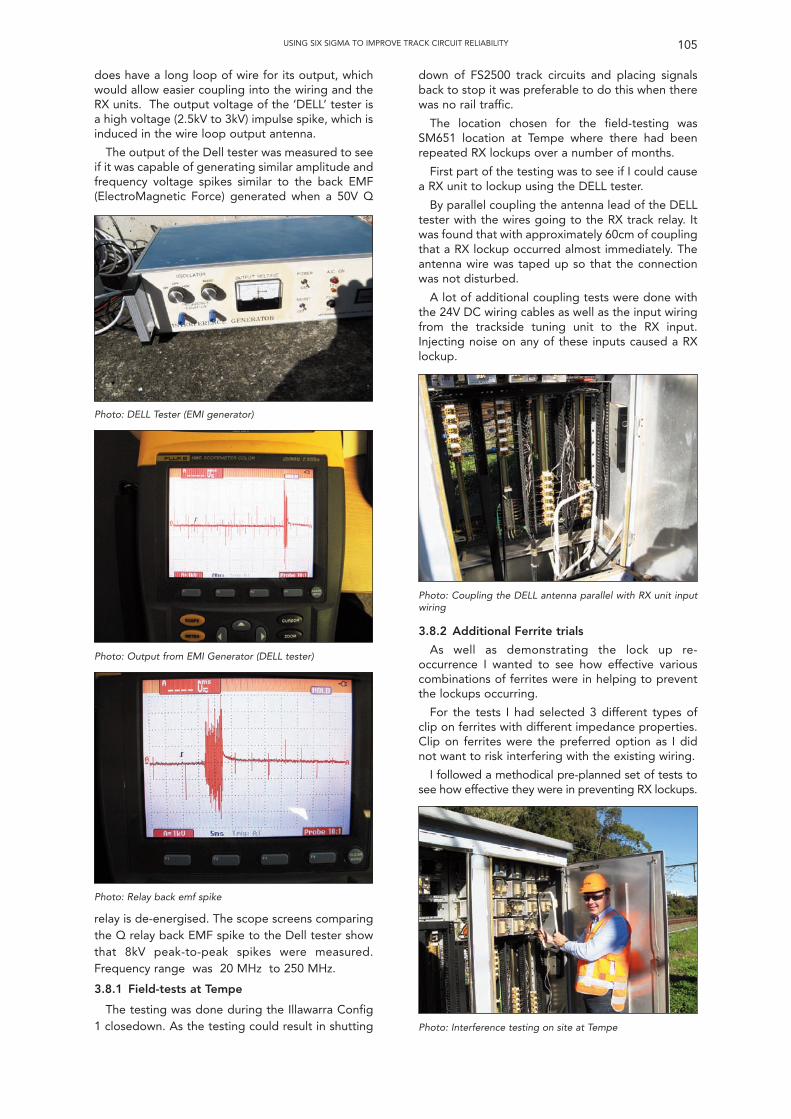
does have a long loop of wire for its output, whichwould allow easier coupling into the wiring and theRX units. The output voltage of the ‘DELL’ tester isa high voltage (2.5kV to 3kV) impulse spike, which isinduced in the wire loop output antenna.
The output of the Dell tester was measured to seeif it was capable of generating similar amplitude andfrequency voltage spikes similar to the back EMF(ElectroMagnetic Force) generated when a 50V Q
down of FS2500 track circuits and placing signalsback to stop it was preferable to do this when therewas no rail traffic.
The location chosen for the field-testing wasSM651 location at Tempe where there had beenrepeated RX lockups over a number of months.
First part of the testing was to see if I could causea RX unit to lockup using the DELL tester.
By parallel coupling the antenna lead of the DELLtester with the wires going to the RX track relay. Itwas found that with approximately 60cm of couplingthat a RX lockup occurred almost immediately. Theantenna wire was taped up so that the connectionwas not disturbed.
A lot of additional coupling tests were done withthe 24V DC wiring cables as well as the input wiringfrom the trackside tuning unit to the RX input.Injecting noise on any of these inputs caused a RXlockup.
105USING SIX SIGMA TO IMPROVE TRACK CIRCUIT RELIABILITY
Photo: DELL Tester (EMI generator)
Photo: Output from EMI Generator (DELL tester)
Photo: Coupling the DELL antenna parallel with RX unit inputwiring
Photo: Interference testing on site at Tempe
Photo: Relay back emf spike
relay is de-energised. The scope screens comparingthe Q relay back EMF spike to the Dell tester showthat 8kV peak-to-peak spikes were measured.Frequency range was 20 MHz to 250 MHz.
3.8.1 Field-tests at Tempe
The testing was done during the Illawarra Config1 closedown. As the testing could result in shutting
3.8.2 Additional Ferrite trials
As well as demonstrating the lock up re-occurrence I wanted to see how effective variouscombinations of ferrites were in helping to preventthe lockups occurring.
For the tests I had selected 3 different types ofclip on ferrites with different impedance properties.Clip on ferrites were the preferred option as I didnot want to risk interfering with the existing wiring.
I followed a methodical pre-planned set of tests tosee how effective they were in preventing RX lockups.
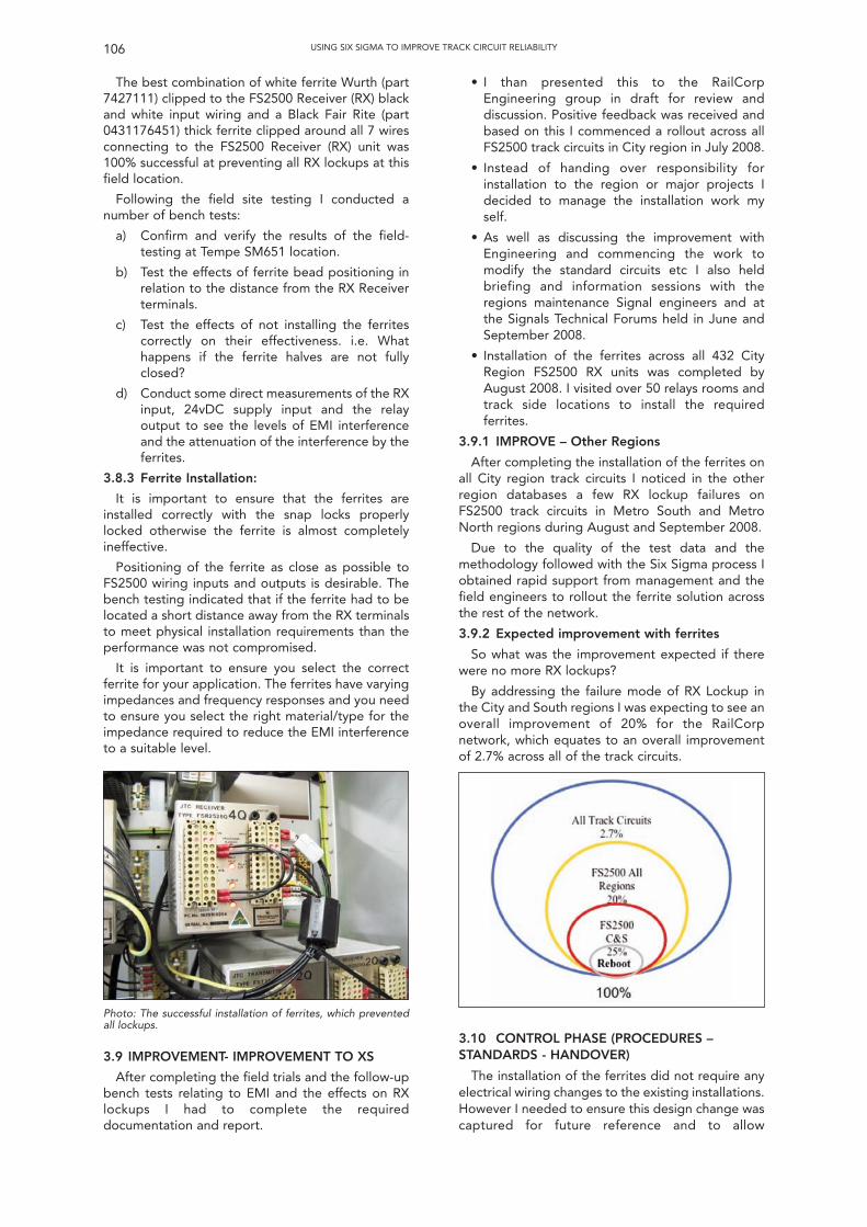
The best combination of white ferrite Wurth (part7427111) clipped to the FS2500 Receiver (RX) blackand white input wiring and a Black Fair Rite (part0431176451) thick ferrite clipped around all 7 wiresconnecting to the FS2500 Receiver (RX) unit was100% successful at preventing all RX lockups at thisfield location.
Following the field site testing I conducted anumber of bench tests:
a) Confirm and verify the results of the field-testing at Tempe SM651 location.
b) Test the effects of ferrite bead positioning inrelation to the distance from the RX Receiverterminals.
c) Test the effects of not installing the ferritescorrectly on their effectiveness. i.e. Whathappens if the ferrite halves are not fullyclosed?
d) Conduct some direct measurements of the RXinput, 24vDC supply input and the relayoutput to see the levels of EMI interferenceand the attenuation of the interference by theferrites.
3.8.3 Ferrite Installation:
It is important to ensure that the ferrites areinstalled correctly with the snap locks properlylocked otherwise the ferrite is almost completelyineffective.
Positioning of the ferrite as close as possible toFS2500 wiring inputs and outputs is desirable. Thebench testing indicated that if the ferrite had to belocated a short distance away from the RX terminalsto meet physical installation requirements than theperformance was not compromised.
It is important to ensure you select the correctferrite for your application. The ferrites have varyingimpedances and frequency responses and you needto ensure you select the right material/type for theimpedance required to reduce the EMI interferenceto a suitable level.
• I than presented this to the RailCorpEngineering group in draft for review anddiscussion. Positive feedback was received andbased on this I commenced a rollout across allFS2500 track circuits in City region in July 2008.
• Instead of handing over responsibility forinstallation to the region or major projects Idecided to manage the installation work myself.
• As well as discussing the improvement withEngineering and commencing the work tomodify the standard circuits etc I also heldbriefing and information sessions with theregions maintenance Signal engineers and atthe Signals Technical Forums held in June andSeptember 2008.
• Installation of the ferrites across all 432 CityRegion FS2500 RX units was completed byAugust 2008. I visited over 50 relays rooms andtrack side locations to install the requiredferrites.
3.9.1 IMPROVE – Other Regions
After completing the installation of the ferrites onall City region track circuits I noticed in the otherregion databases a few RX lockup failures onFS2500 track circuits in Metro South and MetroNorth regions during August and September 2008.
Due to the quality of the test data and themethodology followed with the Six Sigma process Iobtained rapid support from management and thefield engineers to rollout the ferrite solution acrossthe rest of the network.
3.9.2 Expected improvement with ferrites
So what was the improvement expected if therewere no more RX lockups?
By addressing the failure mode of RX Lockup inthe City and South regions I was expecting to see anoverall improvement of 20% for the RailCorpnetwork, which equates to an overall improvementof 2.7% across all of the track circuits.
106 USING SIX SIGMA TO IMPROVE TRACK CIRCUIT RELIABILITY
Photo: The successful installation of ferrites, which preventedall lockups.
3.9 IMPROVEMENT- IMPROVEMENT TO XS
After completing the field trials and the follow-upbench tests relating to EMI and the effects on RXlockups I had to complete the requireddocumentation and report.
3.10 CONTROL PHASE (PROCEDURES –STANDARDS - HANDOVER)
The installation of the ferrites did not require anyelectrical wiring changes to the existing installations.However I needed to ensure this design change wascaptured for future reference and to allow
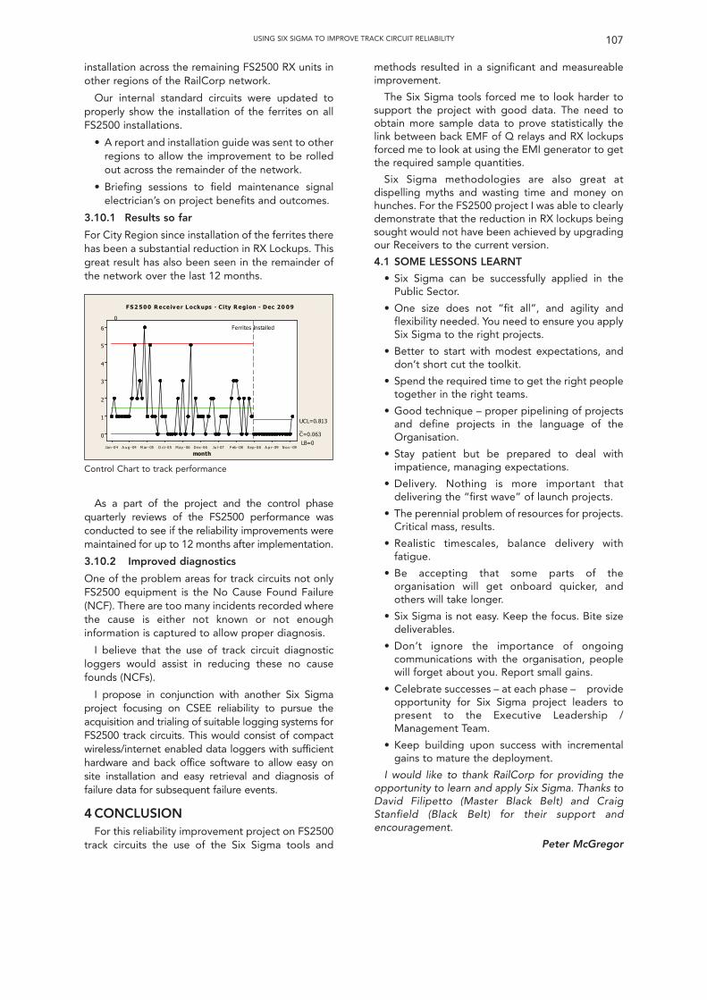
installation across the remaining FS2500 RX units inother regions of the RailCorp network.
Our internal standard circuits were updated toproperly show the installation of the ferrites on allFS2500 installations.
• A report and installation guide was sent to otherregions to allow the improvement to be rolledout across the remainder of the network.
• Briefing sessions to field maintenance signalelectrician’s on project benefits and outcomes.
3.10.1 Results so far
For City Region since installation of the ferrites therehas been a substantial reduction in RX Lockups. Thisgreat result has also been seen in the remainder ofthe network over the last 12 months.
methods resulted in a significant and measureableimprovement.
The Six Sigma tools forced me to look harder tosupport the project with good data. The need toobtain more sample data to prove statistically thelink between back EMF of Q relays and RX lockupsforced me to look at using the EMI generator to getthe required sample quantities.
Six Sigma methodologies are also great atdispelling myths and wasting time and money onhunches. For the FS2500 project I was able to clearlydemonstrate that the reduction in RX lockups beingsought would not have been achieved by upgradingour Receivers to the current version.
4.1 SOME LESSONS LEARNT
• Six Sigma can be successfully applied in thePublic Sector.
• One size does not “fit all”, and agility andflexibility needed. You need to ensure you applySix Sigma to the right projects.
• Better to start with modest expectations, anddon’t short cut the toolkit.
• Spend the required time to get the right peopletogether in the right teams.
• Good technique – proper pipelining of projectsand define projects in the language of theOrganisation.
• Stay patient but be prepared to deal withimpatience, managing expectations.
• Delivery. Nothing is more important thatdelivering the “first wave” of launch projects.
• The perennial problem of resources for projects.Critical mass, results.
• Realistic timescales, balance delivery withfatigue.
• Be accepting that some parts of theorganisation will get onboard quicker, andothers will take longer.
• Six Sigma is not easy. Keep the focus. Bite sizedeliverables.
• Don’t ignore the importance of ongoingcommunications with the organisation, peoplewill forget about you. Report small gains.
• Celebrate successes – at each phase – provideopportunity for Six Sigma project leaders topresent to the Executive Leadership /Management Team.
• Keep building upon success with incrementalgains to mature the deployment.
I would like to thank RailCorp for providing theopportunity to learn and apply Six Sigma. Thanks toDavid Filipetto (Master Black Belt) and CraigStanfield (Black Belt) for their support andencouragement.
Peter McGregor
107USING SIX SIGMA TO IMPROVE TRACK CIRCUIT RELIABILITY
N o v - 09A p r- 09Sep -08F eb -08Ju l-07D ec-06M ay - 06O ct-05M ar- 05A ug -04Jan -04
6
5
4
3
2
1
0
month
_C=0.063
UCL=0.813
LB=0
0
Ferrites Installed
F S 2 500 R ece iv er L ockups - City R egion - Dec 20 09
Control Chart to track performance
As a part of the project and the control phasequarterly reviews of the FS2500 performance wasconducted to see if the reliability improvements weremaintained for up to 12 months after implementation.
3.10.2 Improved diagnostics
One of the problem areas for track circuits not onlyFS2500 equipment is the No Cause Found Failure(NCF). There are too many incidents recorded wherethe cause is either not known or not enoughinformation is captured to allow proper diagnosis.
I believe that the use of track circuit diagnosticloggers would assist in reducing these no causefounds (NCFs).
I propose in conjunction with another Six Sigmaproject focusing on CSEE reliability to pursue theacquisition and trialing of suitable logging systems forFS2500 track circuits. This would consist of compactwireless/internet enabled data loggers with sufficienthardware and back office software to allow easy onsite installation and easy retrieval and diagnosis offailure data for subsequent failure events.
4 CONCLUSIONFor this reliability improvement project on FS2500
track circuits the use of the Six Sigma tools and
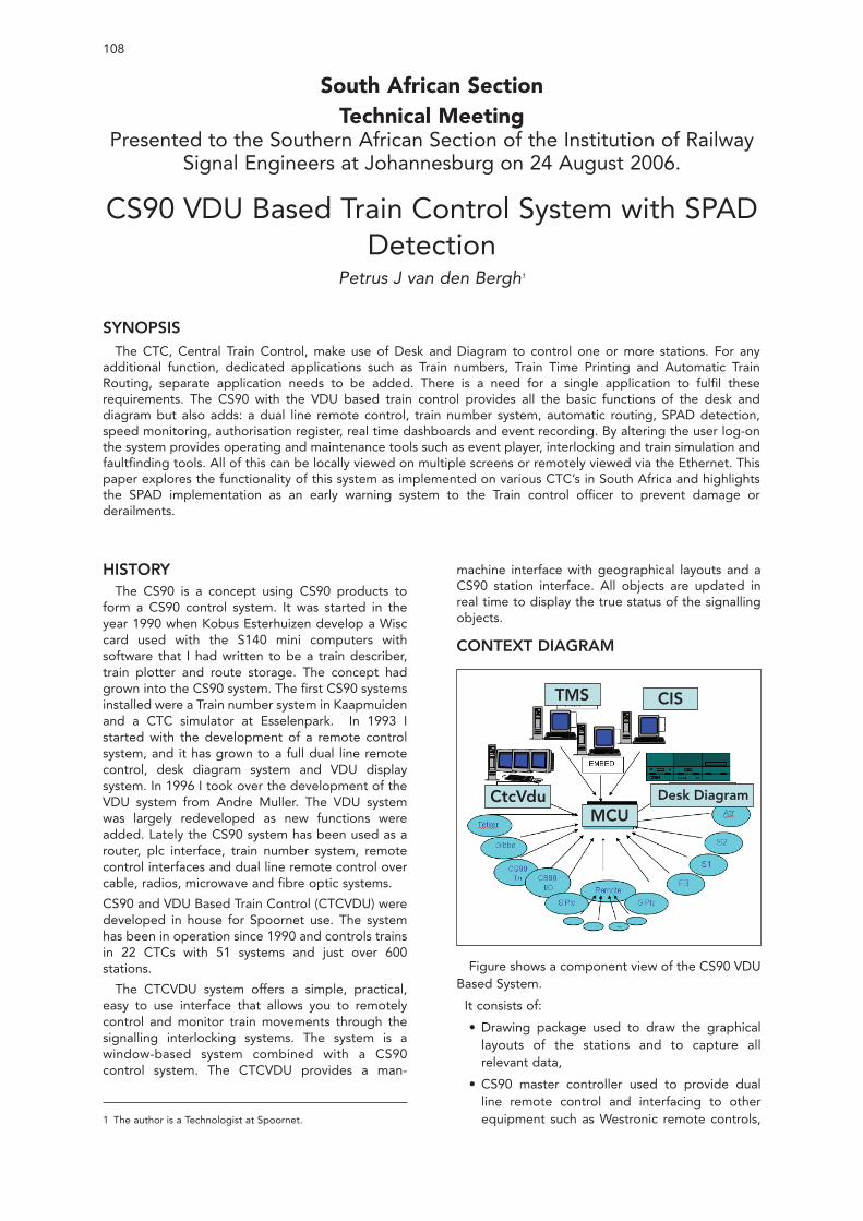
HISTORYThe CS90 is a concept using CS90 products to
form a CS90 control system. It was started in theyear 1990 when Kobus Esterhuizen develop a Wisccard used with the S140 mini computers withsoftware that I had written to be a train describer,train plotter and route storage. The concept hadgrown into the CS90 system. The first CS90 systemsinstalled were a Train number system in Kaapmuidenand a CTC simulator at Esselenpark. In 1993 Istarted with the development of a remote controlsystem, and it has grown to a full dual line remotecontrol, desk diagram system and VDU displaysystem. In 1996 I took over the development of theVDU system from Andre Muller. The VDU systemwas largely redeveloped as new functions wereadded. Lately the CS90 system has been used as arouter, plc interface, train number system, remotecontrol interfaces and dual line remote control overcable, radios, microwave and fibre optic systems.
CS90 and VDU Based Train Control (CTCVDU) weredeveloped in house for Spoornet use. The systemhas been in operation since 1990 and controls trainsin 22 CTCs with 51 systems and just over 600stations.
The CTCVDU system offers a simple, practical,easy to use interface that allows you to remotelycontrol and monitor train movements through thesignalling interlocking systems. The system is awindow-based system combined with a CS90control system. The CTCVDU provides a man-
machine interface with geographical layouts and aCS90 station interface. All objects are updated inreal time to display the true status of the signallingobjects.
CONTEXT DIAGRAM
108
South African SectionTechnical Meeting
Presented to the Southern African Section of the Institution of RailwaySignal Engineers at Johannesburg on 24 August 2006.
CS90 VDU Based Train Control System with SPADDetection
Petrus J van den Bergh1
SYNOPSISThe CTC, Central Train Control, make use of Desk and Diagram to control one or more stations. For any
additional function, dedicated applications such as Train numbers, Train Time Printing and Automatic TrainRouting, separate application needs to be added. There is a need for a single application to fulfil theserequirements. The CS90 with the VDU based train control provides all the basic functions of the desk anddiagram but also adds: a dual line remote control, train number system, automatic routing, SPAD detection,speed monitoring, authorisation register, real time dashboards and event recording. By altering the user log-onthe system provides operating and maintenance tools such as event player, interlocking and train simulation andfaultfinding tools. All of this can be locally viewed on multiple screens or remotely viewed via the Ethernet. Thispaper explores the functionality of this system as implemented on various CTC’s in South Africa and highlightsthe SPAD implementation as an early warning system to the Train control officer to prevent damage orderailments.
1 The author is a Technologist at Spoornet.
TMS CIS
CtcVduMCU
Desk Diagram
Figure shows a component view of the CS90 VDUBased System.
It consists of:
• Drawing package used to draw the graphicallayouts of the stations and to capture allrelevant data,
• CS90 master controller used to provide dualline remote control and interfacing to otherequipment such as Westronic remote controls,
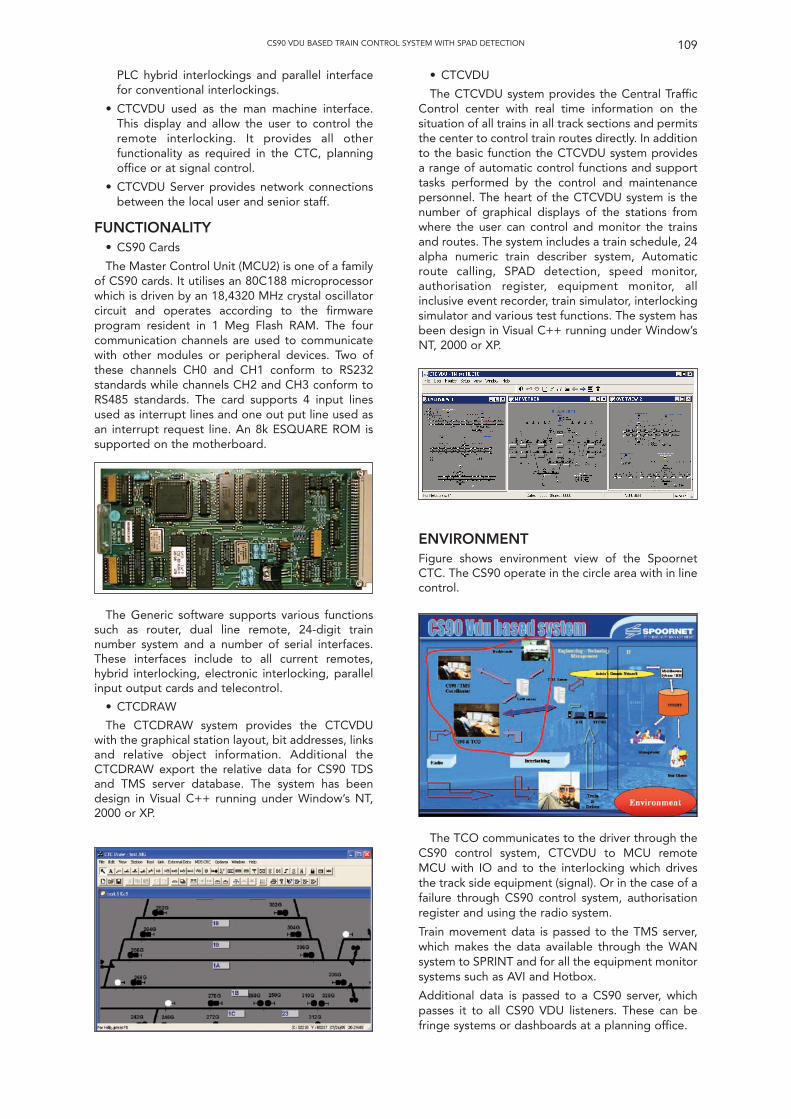
PLC hybrid interlockings and parallel interfacefor conventional interlockings.
• CTCVDU used as the man machine interface.This display and allow the user to control theremote interlocking. It provides all otherfunctionality as required in the CTC, planningoffice or at signal control.
• CTCVDU Server provides network connectionsbetween the local user and senior staff.
FUNCTIONALITY• CS90 Cards
The Master Control Unit (MCU2) is one of a familyof CS90 cards. It utilises an 80C188 microprocessorwhich is driven by an 18,4320 MHz crystal oscillatorcircuit and operates according to the firmwareprogram resident in 1 Meg Flash RAM. The fourcommunication channels are used to communicatewith other modules or peripheral devices. Two ofthese channels CH0 and CH1 conform to RS232standards while channels CH2 and CH3 conform toRS485 standards. The card supports 4 input linesused as interrupt lines and one out put line used asan interrupt request line. An 8k ESQUARE ROM issupported on the motherboard.
• CTCVDU
The CTCVDU system provides the Central TrafficControl center with real time information on thesituation of all trains in all track sections and permitsthe center to control train routes directly. In additionto the basic function the CTCVDU system providesa range of automatic control functions and supporttasks performed by the control and maintenancepersonnel. The heart of the CTCVDU system is thenumber of graphical displays of the stations fromwhere the user can control and monitor the trainsand routes. The system includes a train schedule, 24alpha numeric train describer system, Automaticroute calling, SPAD detection, speed monitor,authorisation register, equipment monitor, allinclusive event recorder, train simulator, interlockingsimulator and various test functions. The system hasbeen design in Visual C++ running under Window’sNT, 2000 or XP.
109CS90 VDU BASED TRAIN CONTROL SYSTEM WITH SPAD DETECTION
The Generic software supports various functionssuch as router, dual line remote, 24-digit trainnumber system and a number of serial interfaces.These interfaces include to all current remotes,hybrid interlocking, electronic interlocking, parallelinput output cards and telecontrol.
• CTCDRAW
The CTCDRAW system provides the CTCVDUwith the graphical station layout, bit addresses, linksand relative object information. Additional theCTCDRAW export the relative data for CS90 TDSand TMS server database. The system has beendesign in Visual C++ running under Window’s NT,2000 or XP.
ENVIRONMENTFigure shows environment view of the SpoornetCTC. The CS90 operate in the circle area with in linecontrol.
The TCO communicates to the driver through theCS90 control system, CTCVDU to MCU remoteMCU with IO and to the interlocking which drivesthe track side equipment (signal). Or in the case of afailure through CS90 control system, authorisationregister and using the radio system.
Train movement data is passed to the TMS server,which makes the data available through the WANsystem to SPRINT and for all the equipment monitorsystems such as AVI and Hotbox.
Additional data is passed to a CS90 server, whichpasses it to all CS90 VDU listeners. These can befringe systems or dashboards at a planning office.
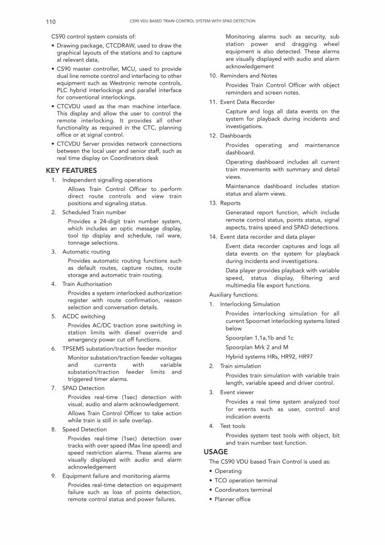
CS90 control system consists of:
• Drawing package, CTCDRAW, used to draw thegraphical layouts of the stations and to captureal relevant data,
• CS90 master controller, MCU, used to providedual line remote control and interfacing to otherequipment such as Westronic remote controls,PLC hybrid interlockings and parallel interfacefor conventional interlockings.
• CTCVDU used as the man machine interface.This display and allow the user to control theremote interlocking. It provides all otherfunctionality as required in the CTC, planningoffice or at signal control.
• CTCVDU Server provides network connectionsbetween the local user and senior staff, such asreal time display on Coordinators desk
KEY FEATURES1. Independent signalling operations
Allows Train Control Officer to performdirect route controls and view trainpositions and signaling status.
2. Scheduled Train number
Provides a 24-digit train number system,which includes an optic message display,tool tip display and schedule, rail ware,tonnage selections.
3. Automatic routing
Provides automatic routing functions suchas default routes, capture routes, routestorage and automatic train routing.
4. Train Authorisation
Provides a system interlocked authorizationregister with route confirmation, reasonselection and conversation details.
5. ACDC switching
Provides AC/DC traction zone switching instation limits with diesel override andemergency power cut off functions.
6. TPSEMS substation/traction feeder monitor
Monitor substation/traction feeder voltagesand currents with variablesubstation/traction feeder limits andtriggered timer alarms.
7. SPAD Detection
Provides real-time (1sec) detection withvisual, audio and alarm acknowledgement.
Allows Train Control Officer to take actionwhile train is still in safe overlap.
8. Speed Detection
Provides real-time (1sec) detection overtracks with over speed (Max line speed) andspeed restriction alarms. These alarms arevisually displayed with audio and alarmacknowledgement
9. Equipment failure and monitoring alarms
Provides real-time detection on equipmentfailure such as loss of points detection,remote control status and power failures.
Monitoring alarms such as security, substation power and dragging wheelequipment is also detected. These alarmsare visually displayed with audio and alarmacknowledgement
10. Reminders and Notes
Provides Train Control Officer with objectreminders and screen notes.
11. Event Data Recorder
Capture and logs all data events on thesystem for playback during incidents andinvestigations.
12. Dashboards
Provides operating and maintenancedashboard.
Operating dashboard includes all currenttrain movements with summary and detailviews.
Maintenance dashboard includes stationstatus and alarm views.
13. Reports
Generated report function, which includeremote control status, points status, signalaspects, trains speed and SPAD detections.
14. Event data recorder and data player
Event data recorder captures and logs alldata events on the system for playbackduring incidents and investigations.
Data player provides playback with variablespeed, status display, filtering andmultimedia file export functions.
Auxiliary functions:
1. Interlocking Simulation
Provides interlocking simulation for allcurrent Spoornet interlocking systems listedbelow
Spoorplan 1,1a,1b and 1c
Spoorplan Mrk 2 and M
Hybrid systems HRs, HR92, HR97
2. Train simulation
Provides train simulation with variable trainlength, variable speed and driver control.
3. Event viewer
Provides a real time system analyzed toolfor events such as user, control andindication events
4. Test tools
Provides system test tools with object, bitand train number test function.
USAGEThe CS90 VDU based Train Control is used as:
• Operating
• TCO operation terminal
• Coordinators terminal
• Planner office
110 CS90 VDU BASED TRAIN CONTROL SYSTEM WITH SPAD DETECTION
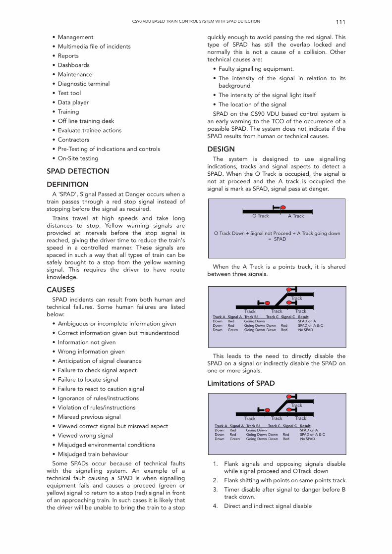
• Management
• Multimedia file of incidents
• Reports
• Dashboards
• Maintenance
• Diagnostic terminal
• Test tool
• Data player
• Training
• Off line training desk
• Evaluate trainee actions
• Contractors
• Pre-Testing of indications and controls
• On-Site testing
SPAD DETECTION
DEFINITIONA 'SPAD', Signal Passed at Danger occurs when a
train passes through a red stop signal instead ofstopping before the signal as required.
Trains travel at high speeds and take longdistances to stop. Yellow warning signals areprovided at intervals before the stop signal isreached, giving the driver time to reduce the train'sspeed in a controlled manner. These signals arespaced in such a way that all types of train can besafely brought to a stop from the yellow warningsignal. This requires the driver to have routeknowledge.
CAUSESSPAD incidents can result from both human and
technical failures. Some human failures are listedbelow:
• Ambiguous or incomplete information given
• Correct information given but misunderstood
• Information not given
• Wrong information given
• Anticipation of signal clearance
• Failure to check signal aspect
• Failure to locate signal
• Failure to react to caution signal
• Ignorance of rules/instructions
• Violation of rules/instructions
• Misread previous signal
• Viewed correct signal but misread aspect
• Viewed wrong signal
• Misjudged environmental conditions
• Misjudged train behaviour
Some SPADs occur because of technical faultswith the signalling system. An example of atechnical fault causing a SPAD is when signallingequipment fails and causes a proceed (green oryellow) signal to return to a stop (red) signal in frontof an approaching train. In such cases it is likely thatthe driver will be unable to bring the train to a stop
quickly enough to avoid passing the red signal. Thistype of SPAD has still the overlap locked andnormally this is not a cause of a collision. Othertechnical causes are:
• Faulty signalling equipment.
• The intensity of the signal in relation to itsbackground
• The intensity of the signal light itself
• The location of the signal
SPAD on the CS90 VDU based control system isan early warning to the TCO of the occurrence of apossible SPAD. The system does not indicate if theSPAD results from human or technical causes.
DESIGNThe system is designed to use signalling
indications, tracks and signal aspects to detect aSPAD. When the O Track is occupied, the signal isnot at proceed and the A track is occupied thesignal is mark as SPAD, signal pass at danger.
111CS90 VDU BASED TRAIN CONTROL SYSTEM WITH SPAD DETECTION
O Track Down + Signal not Proceed + A Track going down= SPAD
O Track A Track
When the A Track is a points track, it is sharedbetween three signals.
This leads to the need to directly disable theSPAD on a signal or indirectly disable the SPAD onone or more signals.
Limitations of SPAD
1. Flank signals and opposing signals disablewhile signal proceed and OTrack down
2. Flank shifting with points on same points track
3. Timer disable after signal to danger before Btrack down.
4. Direct and indirect signal disable
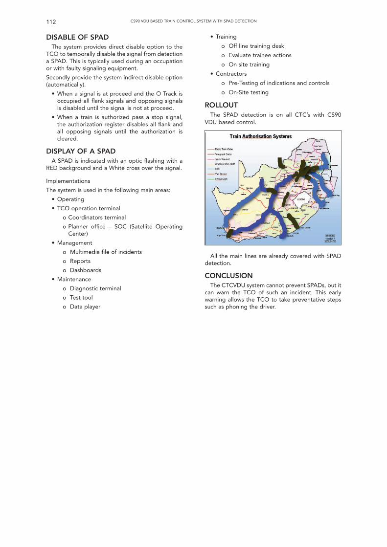
DISABLE OF SPADThe system provides direct disable option to the
TCO to temporally disable the signal from detectiona SPAD. This is typically used during an occupationor with faulty signaling equipment.
Secondly provide the system indirect disable option(automatically).
• When a signal is at proceed and the O Track isoccupied all flank signals and opposing signalsis disabled until the signal is not at proceed.
• When a train is authorized pass a stop signal,the authorization register disables all flank andall opposing signals until the authorization iscleared.
DISPLAY OF A SPADA SPAD is indicated with an optic flashing with a
RED background and a White cross over the signal.
Implementations
The system is used in the following main areas:
• Operating
• TCO operation terminal
o Coordinators terminal
o Planner office – SOC (Satellite OperatingCenter)
• Management
o Multimedia file of incidents
o Reports
o Dashboards
• Maintenance
o Diagnostic terminal
o Test tool
o Data player
• Training
o Off line training desk
o Evaluate trainee actions
o On site training
• Contractors
o Pre-Testing of indications and controls
o On-Site testing
ROLLOUTThe SPAD detection is on all CTC’s with CS90
VDU based control.
112 CS90 VDU BASED TRAIN CONTROL SYSTEM WITH SPAD DETECTION
All the main lines are already covered with SPADdetection.
CONCLUSIONThe CTCVDU system cannot prevent SPADs, but it
can warn the TCO of such an incident. This earlywarning allows the TCO to take preventative stepssuch as phoning the driver.

INTRODUCTIONAn interesting year is nearing its end at the time
of writing. Snow is on the ground right now and wesee our railways trying to cope to satisfy the needsof customers. The perception of the last decades ofmild winter weather has weakened a little the abilityto cope with winter. This observation brings meback to one of my topics: it is people that make thesystem, not the other way around. All kinds oftechnical marvels mean nothing if not applied in aproper way. Nice systems supposed to work underharsh conditions do fail when these conditions aftermany years do arrive. The IRSE is for and aboutpeople; please remember that. I hope that mytheme for the year has been perceived by you topromote that view.
It started early for me with the sudden passingaway of my friend Alan Fisher in February 2009, asituation only formalised when Wim Coenraad asPast President put the Chain of Office around myneck during the AGM in April 2009. The count downhad started for a year in which I felt very muchsupported by everyone, not the least by our capableoffice staff who had to handle yet again a Presidentwho did not live in the UK and who was not availableat short notice. They have done very well under theleadership of our never resting Chief Executive.Colin Porter has been a solid support during theyear and I think I can see that finally we haveunderstood each other up to a level of solid trust. Ithank him for that.
As said by previous Presidents, from the AGM it isall down hill and so it was. My Presidential addressturned the theme of my predecessors in to a peoplething: do we have enough signal engineers in thepipeline to cover both the retirement of ageneration and the increasing demands of themodernisation and expansion of railways around theworld? The International Convention in Madrid,Spain, was well attended and has shown us that ifyou turn your back on this country for a couple ofyears, you will find on your next visit a completelychanged railway. High Speed lines all over thecountry in operation (and successfully so) is what wehave seen, combined with a lot of information abouthow and why the systems were developed. Goodfood too I must say; the only complaints in that areawere about the quantity, perceived by some as toocopious!
More serious issues were presented in thetechnical meetings around the world some of whichI attended. I chaired the London papers but as weare a global organisation the content of these
papers are intended for all and as such we now havea vehicle for that by putting these papers as podcastor vodcast on the web. Knowledge dissemination isa hobby horse of mine hence I encourage thisinitiative and encourage other sections to do thesame and make their papers available to the wholecommunity. Some topics nevertheless I would like tomention. The seminar in London in November onEducation and Career paths for Signal engineersproved to be an eye opener for many present as thetheme resonated with other initiatives already inexistence in some places.
During the year, an exercise started by ourprevious Presidents made progress. Rod Muttramled a group to produce a guidance document forengineers working in the industry to try and containthe ever increasing burden of proof of safety,referred to elsewhere in this report.
During my visits to the North American Sectionand the South African Section I found that my themealso connected with what is happening there. Ageprofile and demands are in line of what we foundduring the seminar, leading to the same issues ofbrain drain and shortage of skills and how to copewith that.
During my long tour to IRSE Sections in Asia andAustralia in mid-late March 2010, my wife and I willhave visited many places and spoken with a lot ofpeople, many of whom we consider friends. At thetime of going to press. having just arrived inSingapore, I can only tell my impression of my visit tothe Indian Section. This is a country with a lot ofchallenges for which a specific local solution must befound due to the size of the network. I visited Delhi,Kolkata and Bangalore, hosted by the very activesection members in these cities. One of my worriesabout people was at least partially answered inBangalore where over 120 signal engineers / IRSEMembers were presented to me, with a very healthyproportion of female signal engineers, at around 35%.
The visit to the Dutch section was of course ahome game for me although formally I could not bea member of the section as I live in Germany butluckily they adopted me.
Some other topics I must mention: the wellorganised technical visit to Glasgow in November2009 and the visit to the Wildenrath Test Centre ofSiemens in February 2010. After all, people do wantto see and touch a live railway (health and safetypermitting; conditions apply in each country in adifferent way).
I could not visit all the UK sections in a proper waybut I know these are alive and kicking having seen
113
The Institution of Railway Signal Engineers(Incorporated 1912)
Ninety-Seventh Annual Report
1st January to 31st December 2009
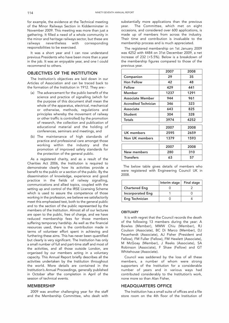
for example, the evidence at the Technical meetingof the Minor Railways Section in Kidderminster inNovember 2009. This meeting was more than just agathering. It filled a need of a whole community inthe minor and heritage railways sector, but these arerailways nevertheless with correspondingresponsibilities to be exercised.
It was a short year and I can now understandprevious Presidents who have been more than a yearin the job. It was an enjoyable year, and one I couldrecommend to others.
OBJECTIVES OF THE INSTITUTIONThe Institution’s objectives are laid down in our
Articles of Association and can be traced back tothe formation of the Institution in 1912. They are:-
(a) The advancement for the public benefit of thescience and practice of signalling (which forthe purpose of this document shall mean thewhole of the apparatus, electrical, mechanicalor otherwise, methods, regulations andprinciples whereby the movement of railwayor other traffic is controlled) by the promotionof research, the collection and publication ofeducational material and the holding ofconferences, seminars and meetings, and
(b) The maintenance of high standards ofpractice and professional care amongst thoseworking within the industry and thepromotion of improved safety standards forthe protection of the general public.
As a registered charity, and as a result of theCharities Act 2006, the Institution is required todemonstrate clearly how its activities provide abenefit to the public or a section of the public. By thedissemination of knowledge, experience and goodpractice in the fields of railway signalling,communications and allied topics, coupled with thesetting up and control of the IRSE Licensing Schemewhich is used to assure the competence of thoseworking in the profession, we believe we satisfactorilymeet this emphasised test, both to the general publicand to the section of the public represented by themembers of the Institution. Almost all of our lecturesare open to the public, free of charge, and we havereduced membership fees for those memberssuffering temporary hardship. As well as the financialresources used, there is the contribution made interms of volunteer effort spent in achieving andfurthering these aims. This has never been quantifiedbut clearly is very significant. The Institution has onlya small number of full and part-time staff and most ofthe activities, and all those outside London, areorganised by our members acting in a voluntarycapacity. This Annual Report briefly describes all theactivities undertaken by the Institution throughoutthe world. More details are contained in theInstitution’s Annual Proceedings, generally publishedin October after the completion in April of thesession of technical events.
MEMBERSHIP2009 was another challenging year for the staff
and the Membership Committee, who dealt with
NINETY-SEVENTH ANNUAL REPORT114
substantially more applications than the previousyear. The Committee, which met on eightoccasions, and considered over 600 applications, ismade up of members from across the industry.Their time and contribution is invaluable to themembership process and is much appreciated.
The registered membership on 1st January 2009was 4252 with 4484 on 31st December 2009, a netincrease of 232 (+5.5%). Below is a breakdown ofthe membership figures compared to those of theprevious year.
OBITUARY
It is with regret that the Council records the deathof the following 13 members during the year: ABowles (Member), MMW Chiu (Member), RJCoulson (Associate), BC Di Marco (Member), DJFeuerherdt (Associate), AJ Fisher (President andFellow), FM Fuller (Fellow), FM Hewlett (Associate), M McGoay (Member), J Reeks (Associate), SARobinson (Associate), F Shaw (Fellow) and GTWhitehouse (Associate).
Council was saddened by the loss of all thesemembers, a number of whom were strongsupporters of the Institution for a considerablenumber of years and in various ways hadcontributed considerably to the Institution’s work,none more so than Alan Fisher,
HEADQUARTERS OFFICEThe Institution has a small suite of offices and a file
store room on the 4th floor of the Institution of
Interim stage Final stage
Chartered Eng 0 2
Incorporated Eng 1 0
Eng Technician 0 4
2007 2008
New members 280 310
Transfers 63 57
2007 2008
UK members 2595 2659
Non UK members 1379 1593
2007 2008
Companion 29 35
Hon Fellow 42 48
Fellow 429 441
Member 1237 1291
Associate Member 944 961
Accredited Technician 346 323
Associate 643 825
Student 304 328
Totals 3974 4252
The below table gives details of members whowere registered with Engineering Council UK in2008.
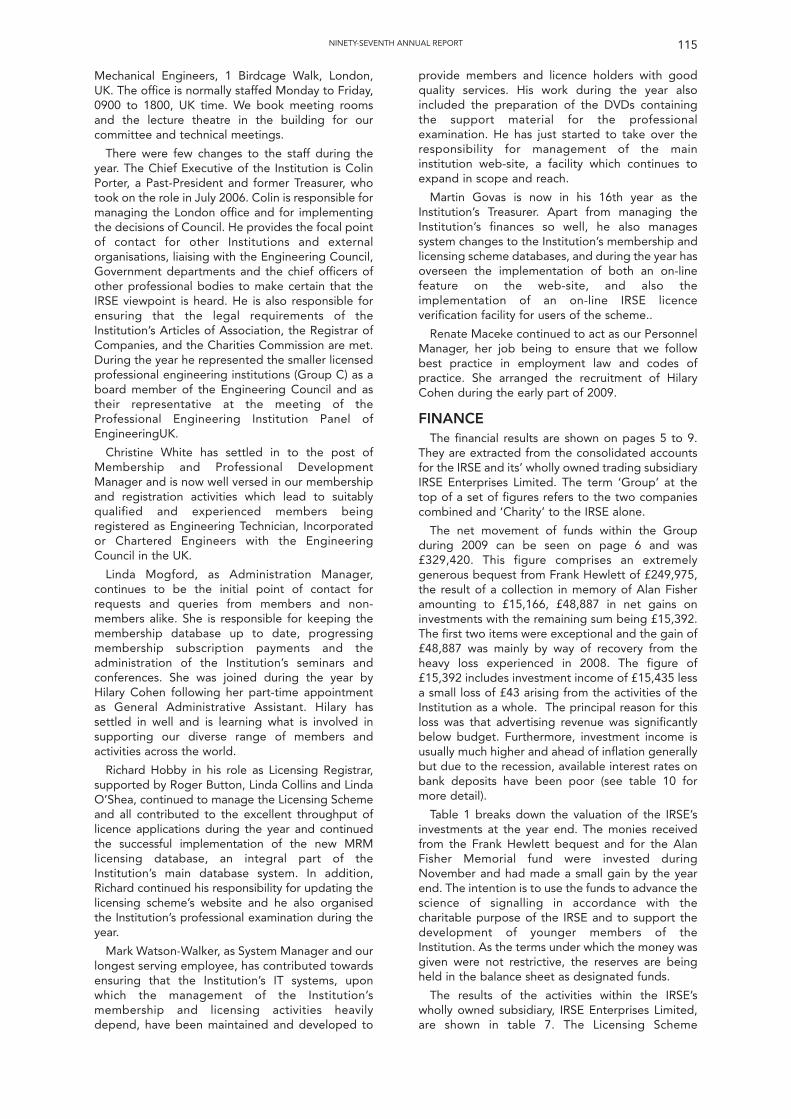
Mechanical Engineers, 1 Birdcage Walk, London,UK. The office is normally staffed Monday to Friday,0900 to 1800, UK time. We book meeting roomsand the lecture theatre in the building for ourcommittee and technical meetings.
There were few changes to the staff during theyear. The Chief Executive of the Institution is ColinPorter, a Past-President and former Treasurer, whotook on the role in July 2006. Colin is responsible formanaging the London office and for implementingthe decisions of Council. He provides the focal pointof contact for other Institutions and externalorganisations, liaising with the Engineering Council,Government departments and the chief officers ofother professional bodies to make certain that theIRSE viewpoint is heard. He is also responsible forensuring that the legal requirements of theInstitution’s Articles of Association, the Registrar ofCompanies, and the Charities Commission are met.During the year he represented the smaller licensedprofessional engineering institutions (Group C) as aboard member of the Engineering Council and astheir representative at the meeting of theProfessional Engineering Institution Panel ofEngineeringUK.
Christine White has settled in to the post ofMembership and Professional DevelopmentManager and is now well versed in our membershipand registration activities which lead to suitablyqualified and experienced members beingregistered as Engineering Technician, Incorporatedor Chartered Engineers with the EngineeringCouncil in the UK.
Linda Mogford, as Administration Manager,continues to be the initial point of contact forrequests and queries from members and non-members alike. She is responsible for keeping themembership database up to date, progressingmembership subscription payments and theadministration of the Institution’s seminars andconferences. She was joined during the year byHilary Cohen following her part-time appointmentas General Administrative Assistant. Hilary hassettled in well and is learning what is involved insupporting our diverse range of members andactivities across the world.
Richard Hobby in his role as Licensing Registrar,supported by Roger Button, Linda Collins and LindaO’Shea, continued to manage the Licensing Schemeand all contributed to the excellent throughput oflicence applications during the year and continuedthe successful implementation of the new MRMlicensing database, an integral part of theInstitution’s main database system. In addition,Richard continued his responsibility for updating thelicensing scheme’s website and he also organisedthe Institution’s professional examination during theyear.
Mark Watson-Walker, as System Manager and ourlongest serving employee, has contributed towardsensuring that the Institution’s IT systems, uponwhich the management of the Institution’smembership and licensing activities heavilydepend, have been maintained and developed to
NINETY-SEVENTH ANNUAL REPORT 115
provide members and licence holders with goodquality services. His work during the year alsoincluded the preparation of the DVDs containingthe support material for the professionalexamination. He has just started to take over theresponsibility for management of the maininstitution web-site, a facility which continues toexpand in scope and reach.
Martin Govas is now in his 16th year as theInstitution’s Treasurer. Apart from managing theInstitution’s finances so well, he also managessystem changes to the Institution’s membership andlicensing scheme databases, and during the year hasoverseen the implementation of both an on-linefeature on the web-site, and also theimplementation of an on-line IRSE licenceverification facility for users of the scheme..
Renate Maceke continued to act as our PersonnelManager, her job being to ensure that we followbest practice in employment law and codes ofpractice. She arranged the recruitment of HilaryCohen during the early part of 2009.
FINANCEThe financial results are shown on pages 5 to 9.
They are extracted from the consolidated accountsfor the IRSE and its’ wholly owned trading subsidiaryIRSE Enterprises Limited. The term ‘Group’ at thetop of a set of figures refers to the two companiescombined and ‘Charity’ to the IRSE alone.
The net movement of funds within the Groupduring 2009 can be seen on page 6 and was£329,420. This figure comprises an extremelygenerous bequest from Frank Hewlett of £249,975,the result of a collection in memory of Alan Fisheramounting to £15,166, £48,887 in net gains oninvestments with the remaining sum being £15,392.The first two items were exceptional and the gain of£48,887 was mainly by way of recovery from theheavy loss experienced in 2008. The figure of£15,392 includes investment income of £15,435 lessa small loss of £43 arising from the activities of theInstitution as a whole. The principal reason for thisloss was that advertising revenue was significantlybelow budget. Furthermore, investment income isusually much higher and ahead of inflation generallybut due to the recession, available interest rates onbank deposits have been poor (see table 10 formore detail).
Table 1 breaks down the valuation of the IRSE’sinvestments at the year end. The monies receivedfrom the Frank Hewlett bequest and for the AlanFisher Memorial fund were invested duringNovember and had made a small gain by the yearend. The intention is to use the funds to advance thescience of signalling in accordance with thecharitable purpose of the IRSE and to support thedevelopment of younger members of theInstitution. As the terms under which the money wasgiven were not restrictive, the reserves are beingheld in the balance sheet as designated funds.
The results of the activities within the IRSE’swholly owned subsidiary, IRSE Enterprises Limited,are shown in table 7. The Licensing Scheme
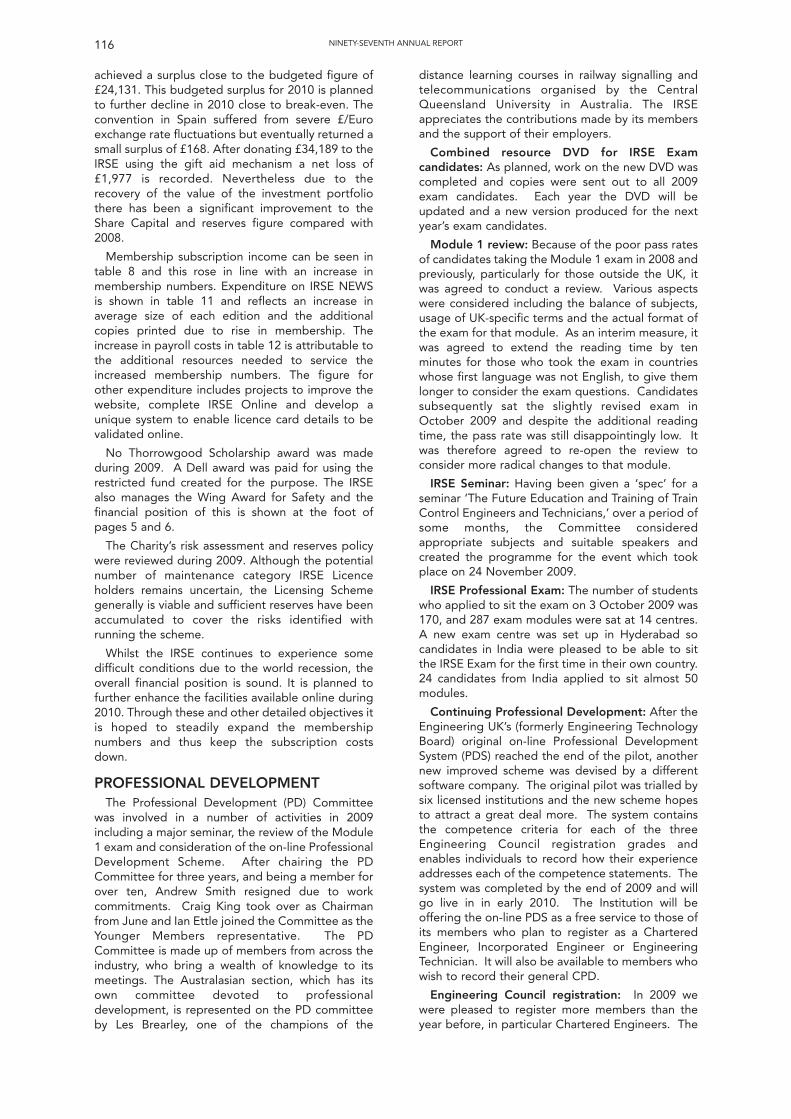
116 NINETY-SEVENTH ANNUAL REPORT
achieved a surplus close to the budgeted figure of£24,131. This budgeted surplus for 2010 is plannedto further decline in 2010 close to break-even. Theconvention in Spain suffered from severe £/Euroexchange rate fluctuations but eventually returned asmall surplus of £168. After donating £34,189 to theIRSE using the gift aid mechanism a net loss of£1,977 is recorded. Nevertheless due to therecovery of the value of the investment portfoliothere has been a significant improvement to theShare Capital and reserves figure compared with2008.
Membership subscription income can be seen intable 8 and this rose in line with an increase inmembership numbers. Expenditure on IRSE NEWSis shown in table 11 and reflects an increase inaverage size of each edition and the additionalcopies printed due to rise in membership. Theincrease in payroll costs in table 12 is attributable tothe additional resources needed to service theincreased membership numbers. The figure forother expenditure includes projects to improve thewebsite, complete IRSE Online and develop aunique system to enable licence card details to bevalidated online.
No Thorrowgood Scholarship award was madeduring 2009. A Dell award was paid for using therestricted fund created for the purpose. The IRSEalso manages the Wing Award for Safety and thefinancial position of this is shown at the foot ofpages 5 and 6.
The Charity’s risk assessment and reserves policywere reviewed during 2009. Although the potentialnumber of maintenance category IRSE Licenceholders remains uncertain, the Licensing Schemegenerally is viable and sufficient reserves have beenaccumulated to cover the risks identified withrunning the scheme.
Whilst the IRSE continues to experience somedifficult conditions due to the world recession, theoverall financial position is sound. It is planned tofurther enhance the facilities available online during2010. Through these and other detailed objectives itis hoped to steadily expand the membershipnumbers and thus keep the subscription costsdown.
PROFESSIONAL DEVELOPMENT The Professional Development (PD) Committee
was involved in a number of activities in 2009including a major seminar, the review of the Module1 exam and consideration of the on-line ProfessionalDevelopment Scheme. After chairing the PDCommittee for three years, and being a member forover ten, Andrew Smith resigned due to workcommitments. Craig King took over as Chairmanfrom June and Ian Ettle joined the Committee as theYounger Members representative. The PDCommittee is made up of members from across theindustry, who bring a wealth of knowledge to itsmeetings. The Australasian section, which has itsown committee devoted to professionaldevelopment, is represented on the PD committeeby Les Brearley, one of the champions of the
distance learning courses in railway signalling andtelecommunications organised by the CentralQueensland University in Australia. The IRSEappreciates the contributions made by its membersand the support of their employers.
Combined resource DVD for IRSE Examcandidates: As planned, work on the new DVD wascompleted and copies were sent out to all 2009exam candidates. Each year the DVD will beupdated and a new version produced for the nextyear’s exam candidates.
Module 1 review: Because of the poor pass ratesof candidates taking the Module 1 exam in 2008 andpreviously, particularly for those outside the UK, itwas agreed to conduct a review. Various aspectswere considered including the balance of subjects,usage of UK-specific terms and the actual format ofthe exam for that module. As an interim measure, itwas agreed to extend the reading time by tenminutes for those who took the exam in countrieswhose first language was not English, to give themlonger to consider the exam questions. Candidatessubsequently sat the slightly revised exam inOctober 2009 and despite the additional readingtime, the pass rate was still disappointingly low. Itwas therefore agreed to re-open the review toconsider more radical changes to that module.
IRSE Seminar: Having been given a ‘spec’ for aseminar ‘The Future Education and Training of TrainControl Engineers and Technicians,’ over a period ofsome months, the Committee consideredappropriate subjects and suitable speakers andcreated the programme for the event which tookplace on 24 November 2009.
IRSE Professional Exam: The number of studentswho applied to sit the exam on 3 October 2009 was170, and 287 exam modules were sat at 14 centres.A new exam centre was set up in Hyderabad socandidates in India were pleased to be able to sitthe IRSE Exam for the first time in their own country.24 candidates from India applied to sit almost 50modules.
Continuing Professional Development: After theEngineering UK’s (formerly Engineering TechnologyBoard) original on-line Professional DevelopmentSystem (PDS) reached the end of the pilot, anothernew improved scheme was devised by a differentsoftware company. The original pilot was trialled bysix licensed institutions and the new scheme hopesto attract a great deal more. The system containsthe competence criteria for each of the threeEngineering Council registration grades andenables individuals to record how their experienceaddresses each of the competence statements. Thesystem was completed by the end of 2009 and willgo live in in early 2010. The Institution will beoffering the on-line PDS as a free service to those ofits members who plan to register as a CharteredEngineer, Incorporated Engineer or EngineeringTechnician. It will also be available to members whowish to record their general CPD.
Engineering Council registration: In 2009 wewere pleased to register more members than theyear before, in particular Chartered Engineers. The
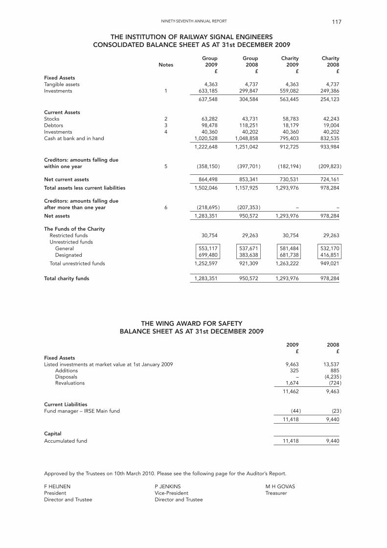
117NINETY-SEVENTH ANNUAL REPORT
THE INSTITUTION OF RAILWAY SIGNAL ENGINEERSCONSOLIDATED BALANCE SHEET AS AT 31st DECEMBER 2009
Group Group Charity CharityNotes 2009 2008 2009 2008
£ £ £ £Fixed AssetsTangible assets 4,363 4,737 4,363 4,737Investments 1 633,185 299,847 559,082 249,386
637,548 304,584 563,445 254,123
Current AssetsStocks 2 63,282 43,731 58,783 42,243Debtors 3 98,478 118,251 18,179 19,004Investments 4 40,360 40,202 40,360 40,202Cash at bank and in hand 1,020,528 1,048,858 795,403 832,535
1,222,648 1,251,042 912,725 933,984
Creditors: amounts falling duewithin one year 5 (358,150 ) (397,701 ) (182,194 ) (209,823 )
Net current assets 864,498 853,341 730,531 724,161
Total assets less current liabilities 1,502,046 1,157,925 1,293,976 978,284
Creditors: amounts falling dueafter more than one year 6 (218,695 ) (207,353 ) – –
Net assets 1,283,351 950,572 1,293,976 978,284
The Funds of the CharityRestricted funds 30,754 29,263 30,754 29,263Unrestricted funds
General 553,117 537,671 581,484 532,170Designated 699,480 383,638 681,738 416,851
Total unrestricted funds 1,252,597 921,309 1,263,222 949,021
Total charity funds 1,283,351 950,572 1,293,976 978,284
THE WING AWARD FOR SAFETYBALANCE SHEET AS AT 31st DECEMBER 2009
2009 2008£ £
Fixed AssetsListed investments at market value at 1st January 2009 9,463 13,537
Additions 325 885Disposals – (4,235 )Revaluations 1,674 (724 )
11,462 9,463
Current LiabilitiesFund manager – IRSE Main fund (44 ) (23 )
11,418 9,440
CapitalAccumulated fund 11,418 9,440
Approved by the Trustees on 10th March 2010. Please see the following page for the Auditor’s Report.
F HEIJNEN P JENKINS M H GOVASPresident Vice-President TreasurerDirector and Trustee Director and Trustee
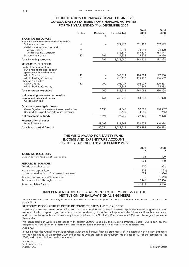
118 NINETY-SEVENTH ANNUAL REPORT
THE INSTITUTION OF RAILWAY SIGNAL ENGINEERSCONSOLIDATED STATEMENT OF FINANCIAL ACTIVITIES
FOR THE YEAR ENDED 31st DECEMBER 2009Total Total
Notes Restricted Unrestricted 2009 2008£ £ £ £
INCOMING RESOURCESIncoming resources from generated funds
Voluntary income 8 – 571,498 571,498 287,449Activities for generating funds:
within Charity 9 – 70,811 70,811 74,090within Trading Company 7 – 585,877 585,877 683,473
Investment income 10 561 14,874 15,435 46,816
Total incoming resources 561 1,243,060 1,243,621 1,091,828
RESOURCES EXPENDEDCosts of generating funds
Fund-raising trading: cost ofgoods sold and other costswithin Charity 11 – 108,534 108,534 97,950within Trading Company 7 – 475,178 475,178 536,609
Charitable activitieswithin Charity 12 300 301,727 302,027 280,267within Trading Company – 77,349 77,349 75,632
Total resources expended 300 962,788 963,088 990,458
Net incoming resources before otherrecognised gains and losses 261 280,272 280,533 101,370
Corporation Tax – – – –
Other recognised gains/losses(Losses)/gains on investment asset revaluation 1,230 51,302 52,532 (90,507 )Realised (loss)/profit on sale of investments – (3,645 ) (3,645 ) (965 )
Net movement in funds 1,491 327,929 329,420 9,898
Reconciliation of FundsBrought forward 29,263 921,309 950,572 940,674
Total funds carried forward 30,754 1,249,238 1,279,992 950,572
THE WING AWARD FOR SAFETY FUNDINCOME AND EXPENDITURE ACCOUNT
FOR THE YEAR ENDED 31st DECEMBER 20092009 2008
£ £INCOMING RESOURCESDividends from fixed asset investments 904 480
904 480RESOURCES EXPENDEDAwards and other costs 600 603
Income less expenditure 304 (123 )Losses on revaluation of fixed asset investments 1,674 (1,496 )
Realised (loss) on sale of investments – (1,305 )Accumulated fund brought forward 9,440 12,364
Funds available for use 11,418 9,440
INDEPENDENT AUDITOR’S STATEMENT TO THE MEMBERS OF THE INSTITUTION OF RAILWAY SIGNAL ENGINEERS
We have examined the summary financial statement in the Annual Report for the year ended 31 December 2009 set out onpages 5 – 9.
RESPECTIVE RESPONSIBILITIES OF THE DIRECTORS/TRUSTEES AND THE AUDITORThe directors/trustees are responsible for preparing the Annual Report in accordance with applicable United Kingdom law. Ourresponsibility is to report to you our opinion on the consistency of the Annual Report with the full annual financial statements,and its compliance with the relevant requirements of section 427 of the Companies Act 2006 and the regulations madethereunder.
We conducted our work in accordance with bulletin 2008/3 issued by the Auditing Practices Board. Our report on thecompany’s full annual financial statements describes the basis of our opinion on those financial statements.
OPINIONIn our opinion the Annual Report is consistent with the full annual financial statements of The Institution of Railway Engineersfor the year ended 31 December 2009 and complies with the applicable requirements of section 427 of the companies Act2006, and the regulations made thereunder.
Ian Katté Statutory auditorAddlestone 10 March 2010
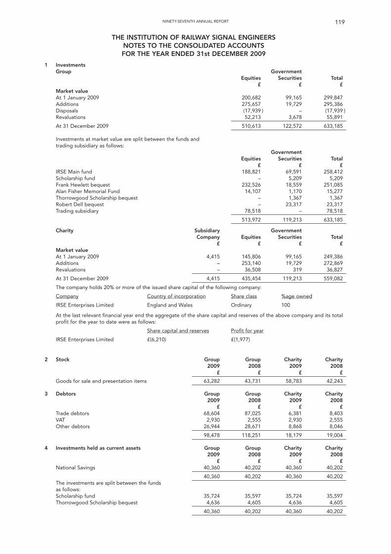
119NINETY-SEVENTH ANNUAL REPORT
THE INSTITUTION OF RAILWAY SIGNAL ENGINEERSNOTES TO THE CONSOLIDATED ACCOUNTSFOR THE YEAR ENDED 31st DECEMBER 2009
1 InvestmentsGroup Government
Equities Securities Total£ £ £
Market valueAt 1 January 2009 200,682 99,165 299,847Additions 275,657 19,729 295,386Disposals (17,939 ) – (17,939 )Revaluations 52,213 3,678 55,891
At 31 December 2009 510,613 122,572 633,185
Investments at market value are split between the funds andtrading subsidiary as follows:
GovernmentEquities Securities Total
£ £ £IRSE Main fund 188,821 69,591 258,412Scholarship fund – 5,209 5,209Frank Hewlett bequest 232,526 18,559 251,085Alan Fisher Memorial Fund 14,107 1,170 15,277Thorrowgood Scholarship bequest – 1,367 1,367Robert Dell bequest – 23,317 23,317Trading subsidiary 78,518 – 78,518
513,972 119,213 633,185
Charity Subsidiary GovernmentCompany Equities Securities Total
£ £ £ £Market valueAt 1 January 2009 4,415 145,806 99,165 249,386Additions – 253,140 19,729 272,869Revaluations – 36,508 319 36,827
At 31 December 2009 4,415 435,454 119,213 559,082
The company holds 20% or more of the issued share capital of the following company:
Company Country of incorporation Share class %age owned
IRSE Enterprises Limited England and Wales Ordinary 100
At the last relevant financial year end the aggregate of the share capital and reserves of the above company and its totalprofit for the year to date were as follows:
Share capital and reserves Profit for year
IRSE Enterprises Limited £(6,210) £(1,977)
2 Stock Group Group Charity Charity2009 2008 2009 2008
£ £ £ £
Goods for sale and presentation items 63,282 43,731 58,783 42,243
3 Debtors Group Group Charity Charity2009 2008 2009 2008
£ £ £ £Trade debtors 68,604 87,025 6,381 8,403VAT 2,930 2,555 2,930 2,555Other debtors 26,944 28,671 8,868 8,046
98,478 118,251 18,179 19,004
4 Investments held as current assets Group Group Charity Charity2009 2008 2009 2008
£ £ £ £National Savings 40,360 40,202 40,360 40,202
40,360 40,202 40,360 40,202The investments are split between the fundsas follows:Scholarship fund 35,724 35,597 35,724 35,597Thorrowgood Scholarship bequest 4,636 4,605 4,636 4,605
40,360 40,202 40,360 40,202
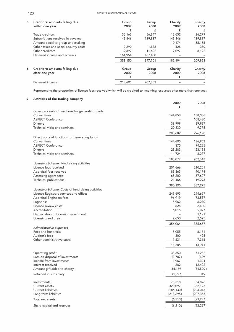
120 NINETY-SEVENTH ANNUAL REPORT
5 Creditors: amounts falling due Group Group Charity Charitywithin one year 2009 2008 2009 2008
£ £ £ £Trade creditors 35,163 56,847 18,652 26,279Subscriptions received in advance 145,846 139,887 145,846 139,887Amount owed to group undertaking – – 10,174 35,135Other taxes and social security costs 2,290 1,888 425 350Other creditors 9,897 11,622 7,097 8,172Deferred income and accruals 164,954 187,458 – –
358,150 397,701 182,194 209,823
6 Creditors: amounts falling due Group Group Charity Charityafter one year 2009 2008 2009 2008
£ £ £ £
Deferred income 218,695 207,353 – –
Representing the proportion of licence fees received which will be credited to Incoming resources after more than one year.
7 Activities of the trading company2009 2008
£ £Gross proceeds of functions for generating funds:Conventions 144,853 138,006ASPECT Conference – 108,430Dinners 39,999 39,987Technical visits and seminars 20,830 9,775
205,682 296,198Direct costs of functions for generating funds:Conventions 144,695 136,953ASPECT Conference 375 94,225Dinners 25,283 23,188Technical visits and seminars 14,724 8,277
185,077 262,643Licensing Scheme: Fundraising activitiesLicence fees received 201,666 210,201Appraisal fees received 88,863 90,174Assessing agent fees 68,200 67,607Technical publications 21,466 19,293
380,195 387,275Licensing Scheme: Costs of fundraising activitiesLicence Registrars services and offices 243,693 244,657Appraisal Engineers fees 96,919 73,537Logbooks 5,962 6,270Licence review costs 825 2,400Accreditation 6,015 5,077Depreciation of Licensing equipment – 1,191Licensing audit fee 2,650 2,525
356,064 335,657Administrative expensesFees and honoraria 3,055 6,151Auditor’s fees 800 425Other administrative costs 7,531 7,365
11,386 13,941
Operating profit 33,350 71,232Loss on disposal of investments (3,787 ) (129 )Income from investments 1,967 1,324Interest received 682 12,422Amount gift aided to charity (34,189 ) (84,500 )
Retained in subsidiary (1,977 ) 349
Investments 78,518 54,876Current assets 320,097 352,193Current liabilities (186,130 ) (223,013 )Long term liabilities (218,695 ) (207,353 )
Total net assets (6,210 ) (23,297 )
Share capital and reserves (6,210 ) (23,297 )
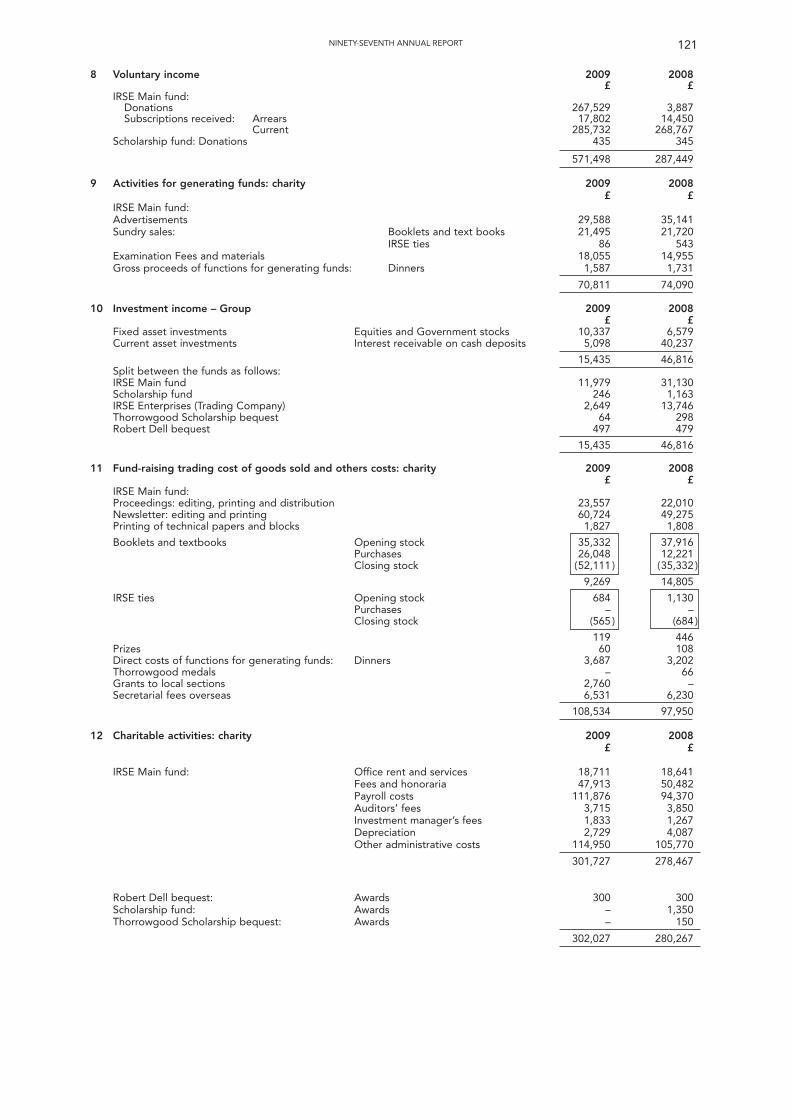
NINETY-SEVENTH ANNUAL REPORT 121
8 Voluntary income 2009 2008£ £
IRSE Main fund:Donations 267,529 3,887Subscriptions received: Arrears 17,802 14,450
Current 285,732 268,767Scholarship fund: Donations 435 345
571,498 287,449
9 Activities for generating funds: charity 2009 2008£ £
IRSE Main fund:Advertisements 29,588 35,141Sundry sales: Booklets and text books 21,495 21,720
IRSE ties 86 543Examination Fees and materials 18,055 14,955Gross proceeds of functions for generating funds: Dinners 1,587 1,731
70,811 74,090
10 Investment income – Group 2009 2008£ £
Fixed asset investments Equities and Government stocks 10,337 6,579Current asset investments Interest receivable on cash deposits 5,098 40,237
15,435 46,816Split between the funds as follows:IRSE Main fund 11,979 31,130Scholarship fund 246 1,163IRSE Enterprises (Trading Company) 2,649 13,746Thorrowgood Scholarship bequest 64 298Robert Dell bequest 497 479
15,435 46,816
11 Fund-raising trading cost of goods sold and others costs: charity 2009 2008£ £
IRSE Main fund:Proceedings: editing, printing and distribution 23,557 22,010Newsletter: editing and printing 60,724 49,275Printing of technical papers and blocks 1,827 1,808
Booklets and textbooks Opening stock 35,332 37,916Purchases 26,048 12,221Closing stock (52,111 ) (35,332 )
9,269 14,805
IRSE ties Opening stock 684 1,130Purchases – –Closing stock (565 ) (684 )
119 446Prizes 60 108Direct costs of functions for generating funds: Dinners 3,687 3,202Thorrowgood medals – 66Grants to local sections 2,760 –Secretarial fees overseas 6,531 6,230
108,534 97,950
12 Charitable activities: charity 2009 2008£ £
IRSE Main fund: Office rent and services 18,711 18,641Fees and honoraria 47,913 50,482Payroll costs 111,876 94,370Auditors’ fees 3,715 3,850Investment manager’s fees 1,833 1,267Depreciation 2,729 4,087Other administrative costs 114,950 105,770
301,727 278,467
Robert Dell bequest: Awards 300 300Scholarship fund: Awards – 1,350Thorrowgood Scholarship bequest: Awards – 150
302,027 280,267
number of members who pay their fees throughIRSE also increased, by almost 14%. We willcontinue to encourage Engineering Councilregistration.
AWARDSFrank Hewlett Bequest
Frank Hewlett was an Associate of the Institution,having joined in April 1979. He had spent his careermainly as a telecommunications engineer with theGeneral Post Office/British Telecomm in the UK. Hedied in September 2008 and during 2009, theInstitution was advised that he had left a mostgenerous bequest of a third of his estate to theInstitution. So far, £250,000 has been received andthis has been invested. In line with Frank’s wish forthe Institution to use the bequest to support thedevelopment of younger members and theInstitution, Council has decided that for the nexttwo years, they will use the income from theinvestments to provide travelling bursaries toyounger members to support their attendance atthe International Technical Convention. Full detailsand application forms will be circulated to allyounger members prior to the 2010 Convention.
Alan Fisher Memorial Fund
Our President in 2008/9, Alan Fisher, diedunexpectedly in February 2009 just before the endof his Presidential year. Council launched an appealfor money to establish a memorial fund in hismemory, with the intention of using the fund tosupport the development of young S&T engineers,particularly those outside the UK. Alan had been adriving force in promoting professionaldevelopment and learning in connection with theIRSE examination to young engineers in Thailand. Atotal of over £15,000 was raised during 2009 for thefund, and thanks are due to those members whoresponded, and particularly to Bombardier RailControl Systems, Alan’s former employer, who madea substantial contribution. The amount received hasbeen invested, and Council agreed to couple theincome received from the investments with thatfrom the Frank Hewlett bequest to fund thetravelling bursaries for two years, as describedabove.
IRSE Network Rail S&T Apprenticeship of theYear
This new award was created in 2008 for NetworkRail’s outstanding apprentice. The award is madeup of a trophy kindly donated by the Unipart ServiceCentre at York; a cheque for £100; and a year’s freeInstitution membership. This year the award waspresented to Mr Kyle Poppy by the Chief Executiveat Network Rail’s annual awards ceremony at theirtraining facility at HMS Collingswood nearPortsmouth on 12th June 2009.
Thorrowgood Scholarship
The Thorrowgood scholarship is awarded annuallyunder a bequest of the late W J Thorrowgood (PastPresident) to assist the development of a youngengineer employed in the signalling andtelecommunications field of engineering and takes
the form of an engraved medallion and a cheque fora sum to be used to finance a study tour of railwaysignalling installations or signalling manufacturingfacilities. The award is made to the Institution youngmember attaining at least a pass with credit in fourmodules in the Institution’s examination.
There was no award made in 2008 as no candidateachieved the necessary qualifying pass marks.
Dell Award
Under a bequest made by the late Robert DellOBE (Past President) this award is made to anemployee of London Underground Ltd or itssuccessor bodies for achievement of a high standardof skill in the science and application of railwaysignalling. The winner of the 2009 Dell Award was MrAndy Heath of London Underground Ltd and he waspresented with his award by the retiring President atthe Annual General Meeting in April 2009.
Wing Award for Safety
The 2009 Wing Award for Safety, commemoratingthe life and work of the late Peter Wing (Fellow),was presented to Mr Mark Wild of WestinghouseRail Systems by the Secretary of State for Transport,Lord Adonis, at a Modern Railways’ awardsceremony held on 26th June 2009 in London. Theaward was in recognition of his leadership inimproving the safety performance of theWestinghouse Signals staff over a number of years.
IRSE Merit Award
At its December 2006 meeting, following asuggestion from one of the members of theInstitution, Council agreed to the formation of IRSEMerit Awards. These are presented to rewardmeritorious service to the Institution. The award ismade by the Council following consideration of anomination made by either an individual who knowsof the contribution of the person, a Local Section,another body in the rail industry, one of the IRSEcommittees or Council itself. Meritorious service isdefined as making a substantial contribution to theInstitution’s work over a period of time byorganising activities, or carrying out specific taskswhich have furthered the Institution’s aims andobjectives. The award takes the form of a plaquemounted on a rectangular plinth, approximately150mm x 100mm, containing the Institution badgeand an engraved citation. No awards were made in2009
LICENSING2009 was another busy year for the Licensing
Scheme. It continues to meet the demands of theindustry with over 1500 licences issued during theyear and the number of valid licences held at theend of the year was over 6300. Sales of the IRSEProfessional Development Log Book also continuedto be high with over 740 being sold.
2009 saw the provisional approval of 2 AssessingAgencies and subsequent full approval of 1, thus thenumber of Assessing Agents stands currently at 33.The scheme continues to attract interest fromoverseas, particularly from India, where the numberof licences issued continues to increase. The 2009
NINETY-SEVENTH ANNUAL REPORT122
123
audit programme was completed in a timely mannerthanks to the hard work of the Appraisal TeamMembers.
As part of our ongoing two-way communicationwith users of the Scheme one Appraisal TeamMembers’ meeting and two Assessing Agencymeetings were held during the year. Attendees atthe last Assessing Agency Meeting were asked tocomplete a survey regarding the perceptions of theLicensing Scheme in the Signalling andTelecommunications industry. The survey attractedan 80% response rate and a summary of theresponses received to the survey has been sent to allattendees of the meeting and will be used to informthe improvement actions that the Scheme willundertake.
The Licensing Scheme website continues tooperate specifically for IRSE licensing. Its address iswww.irselicences.co.uk and a thorough re-design ofthe site will be undertaken in 2010. The newlydesigned site will still contain both generalinformation about licensing (how to obtain a licence,maintaining a logbook etc.) and also thecompetence assessment checklists, which are usedto assess competence for the various categories butthe intention is to make it more user-friendly and itwill follow the IRSE’s new branding. From the 1stJanuary 2009–31st December 2009 the websiteexperienced 67,610 sessions and a total number748,300 hits.
In April 2009 the IRSE underwent a successfulaudit from the United Kingdom AccreditationService (UKAS) against ISO17024 at which 4 findingswere raised that required mandatory action and onethat proposed recommended action. The Schemecontinues to hold full approval against theinternational standard to which it is assessed. Inaddition to this external audit, internal audits of thescheme were carried out.
In 2008 the Licensing Scheme dealt with acomplaint against a licence holder in accordance withthe Scheme procedures and the outcome of the casewas that the licence holder’s licence was revoked.The licence holder appealed against the revocation,the appeal was heard, dismissed and the revocationwas upheld. The licence holder then appealed to theCouncil of the Institution. This second appeal wasalso dismissed and the revocation was again upheld.The licence holder then took the Institution to Courtfor a Judicial Review of the case. The Judicial Reviewtook place in the High Court of Justice, Queen’sBench Division, Administrative Court in the Strand,London on 31 March 2009. The judge havingconsidered the merits of the case brought by thelicence holder against the IRSE decided that therewas no merit in the case and awarded the Institutioncosts against the licence holder. Steps have beentaken to recover the costs awarded. Although theInstitution would have wished to avoid the time andcosts involved in pursuing this case to the ultimatelimit of the UK legal procedure, it is at least is re-assuring to receive confirmation from the Court thatthe Licensing Scheme’s processes and procedures areadequate and fair.
NINETY-SEVENTH ANNUAL REPORT
The Licensing Scheme carried out a number ofinitiatives in 2009 two of which were designed toensure consistency of assessments across AssessingAgencies. These consisted of standardisationexercises for both the Design and Testing licencecategories. Both exercises revealed that althoughthe assessment processes varied slightly betweenAssessing Agencies there was a consistentinterpretation of the requirements of theCompetence Assessment Checklists.
Following on from the ‘fraudulent licence’incident that was reported in 2008, an online licencevalidation system has been implemented thatenables any individual to check the validity of alicence online by entering key information shown ona licence card. If the data entered into the licencevalidation system matches the information held bythe IRSE then a positive responses is provided to theuser. If the information does not match theinformation held on the IRSE licensing databasethen the user is asked to contact the IRSE for furtherinformation.
For some time the Licensing Scheme has beenreceiving queries regarding the provision of licencesfor train-borne control systems. In 2008/2009 aworking group of interested cross-industryrepresentatives led the production of a guidancedocument designed to help organisations makepragmatic risk based decisions about how tomanage the competence of persons working ontrain-borne train control systems at all phases of thesystem lifecycle. The guidance document has nowbeen completed and is available both on-line andfrom the Institution.
The complaints process continues to operate forcompanies or individuals wishing to register acomplaint about a licence holder’s licensable work.In 2009 11 complaints were received andsubsequently investigated.
The staff within the Licensing Office has remainedun-changed with Richard Hobby continuing his roleas Licensing Registrar, Linda Collins concentratingher efforts on the financial/credit control aspects ofthe scheme and Roger Button and Linda O’Sheaundertaking Certification and Competence AssessorApproval duties respectively. The LicensingCommittee remains unchanged with the exceptionof Les Braithwaite from Signalling Solutionsreplacing Thomas Godfrey who relocated withinBombardier to Thailand.
ANNUAL GENERAL MEETINGThe 96th Annual General Meeting chaired by
Past-President Mr W J Coenraad as a result of thedeath of the President Mr AJ Fisher in February2009, was held at the Institution of MechanicalEngineers, Birdcage Walk, Westminster, London onFriday 24th April 2009 when the composition of thenew Council was announced, as follows:
President: F Heijnen
Vice Presidents: PA Jenkins
Mrs CL Porter
Members of Council from class of Fellow
F How Dr AF Rumsey
J Irwin C Sevestre
I Mitchell A Simmons
Miss A Parker GJ Simpson
CR Page DN Weedon
Members of Council from Class of Member
JJ Aitken AS Kornas
I Allison Dr DN Woodland
PJ Grant N Wright
Members of Council from Class of AssociateMember
Miss LC Simón Vena D Young
The formal proceedings included a warm vote ofthanks to the following member retiring fromCouncil for his valuable service to the work of theInstitution.
Mr BD Chowdhury, Council member for 2 years.
ELECTION OF HONORARY FELLOWS
The Chairman announced that the Council haddecided to elect the following to become HonoraryFellows of the Institution in recognition of their longand distinguished service to the profession and tothe IRSE.
Jacques Poré, President 2005/2006
Chandrika Prasad
In addition, the Chairman announced that Councilhad agreed to make a posthumous award ofHonorary Fellow to Alan Fisher for his majorcontribution to the profession and the Institutionover many years. A presentation of his certificate ofHonorary Fellowship and his Past-President’smedallion was then made to Mrs Jennie Fisher, AlanFishers widow.
This was followed by the inauguration of the newPresident, Mr F Heijnen, who gave his PresidentialAddress.
COUNCIL MEETINGSSeven meetings of the Council were held during
the year during which the business of the Institutionwas conducted. During the year, Mr D Youngresigned from the Council in October 2009 and MrS Eastmond was co-opted to fill the resultingvacancy. The Articles of Association provide for thecurrent Chairmen of all local sections, both in andoutside the UK, and also Country Vice-Presidents toattend Council meetings and Council is alwayspleased to welcome any who are able to be presentat a Council meeting in London.
IRSE ENTERPRISES LTDAs mentioned in the finance section of this report,
IRSE Enterprises Ltd is the trading company whollyowned by the Institution. The trading companyhandles a number of activities which are associatedwith but outside the direct scope of the charity. TheDirectors appointed for the year 2009/10 were:
Chairman JD Francis
The Junior Vice-President Mrs CL Porter
The Chairman of Finance Committee WJ Coenraad
The IRSE Treasurer MH Govas
The IRSE Chief Executive CH Porter
Any profits from the company where possible aregift-aided back to the Institution.
EXTERNAL AND INTERNAL AUDITThe finances of the Institution are subject to audit
annually by independent external auditors whosubmit their report to the Annual General Meeting.The Licensing Scheme is subject to ongoing annualexternal audit by the United Kingdom AccreditationService (UKAS). As a registered Charity theInstitution is subject to periodic external review bythe Charity Commission. As an Institution licensedby the Engineering Council to register Charteredand Incorporated Engineers and EngineeringTechnicians, the Institution is also subject to reviewperiodically by the Engineering Council to ensurecompliance with Engineering Council registrationstandards. The last Engineering Council review visittook place in June 2006 and was satisfactorilyconcluded. There was an external audit of theLicensing Scheme by UKAS during 2009 and this iscovered in the licensing section of this report.
In March 2000 Council decided to set up aprocess whereby an internal audit committeecomprising senior Fellows of the Institution would,over a period of time, undertake independentinternal scrutiny of the Institution’s management ofall its activities not subject to formal external audits.The internal auditors report annually to Council andCouncil uses their reports and the recommendationsthat they make to continually improve themanagement of the Institution’s affairs and thedelivery of its services to members. During 2009/10,audits on the operation of the finance andinternational technical committees were concluded,and an audit on external perceptions of the licensingscheme and its contribution to the Institution’scharitable status started. Finally, the operation ofthe Licensing Scheme is subject to internal audit asreported in the Licensing section of this report.
ANNUAL DINNERThe 45th Annual Dinner was again held this year
at the Sheraton Park Lane Hotel, Piccadilly, Londonon Friday 24th April 2009 following the AnnualGeneral Meeting. 435 members and their guestswere present. There was a repeat appearance ofdouble-decker bus to transport members betweenthe AGM at 1 Birdcage Walk and the hotel, and thisyear it included a circumnavigation of Marble Archto help prepare the members on board for aconvivial evening.
Frans Heijnen, the newly installed President,introduced his guests for the evening, with his guestof honour being James Drummond, the Presidentand Chief Executive Officer of the Invensys RailGroup, of which Westinghouse Rail Systems is a keymember. He emphasised the significantopportunities for the signalling industry in
NINETY-SEVENTH ANNUAL REPORT124 -
forthcoming years but only if the industry played itsfull contribution in realising efficiency gains andlower overall costs. He later proposed a toast to theInstitution. The President responded by proposing atoast to the guests, after which, desert was served. A collection carried out during the meal for theRailway Benefit Fund (RBF) raised over £3800 for theFund.
Council continues to be grateful for all the hardwork that Mr Quentin Macdonald and the IRSE staffundertake every year to ensure the success of thispopular event.
MEMBERS’ LUNCHEON105 members including 16 Past Presidents
attended the eleventh annual Members’ Luncheonheld on 17th June 2009 at the at the Victory ServicesClub in Seymour Street London. Our longest servingPast President, Victor Smith OBE, who wasPresident in 1974 and also 30 members of the 81members with over 50 years membership wereamongst the members present. A very pleasant 3-course luncheon with wine was served.
The group was then addressed by the President,Frans Heijnen, the 85th person to serve as Presidentsince the Institution’s formation in 1912 who saidhow pleased he was to be able to attend and gavebrief details of his forthcoming programme. TheChief Executive, Colin Porter then went on to detailthe ten newcomers to the 50 year list; Denys Dyson,Michael Hynd, Roger Kingstone, Colin Law, BarbaraPerkin, Tony Pinkstone, Gordon Rendle, Mike Thwaite, Rod Townsend and S C Yip fromMalaysia. He went on to describe the currentmembership figures for the Institution, whichcontinued a steady upward trend.
Members attending the luncheon with over 50years membership of the Institution were Messrs DR Bowlby, D Graham Brown, David G Brown, V Brown, R Bugler, KW Burrage, R Clements, D Dyson, LT Eccles, JH Fensom, Alan Fleet, A D(Tony) Fleet, RS Gilbert, C Hale, B Hesketh, B Hillier, F Hounsom, MS Hynd,RL Kingstone, IMPage, RA Pinkstone, DT Plummer, JP Raindle, FG Rayers, GEJ Rendle, RF Rowland, VH SmithOBE, PC Taylor, R Thatcher, M Thwaite, AH Walker,J Waller and MF Wilkins.
Past Presidents present at the luncheon wereMessrs WG Boddy, JD Corrie, JD Francis, EOGoddard, C Hale, TS Howard, AC Howker, C Kessell,RC Nelson, CA Porter, CH Porter, VH Smith, J Waller, AD Wilson and FP Wiltshire.
The luncheon as ever concluded in its usual happyatmosphere of friendship and camaraderie and wasthoroughly enjoyed by all present. The eventprovides an opportunity to meet members, youngand old, who are interested in the Institution and inmany cases, have devoted a considerable amount oftheir time to the furtherance of the Institution’sobjectives over many years.
INTERNATIONAL CONVENTIONThe International Convention was held in Madrid,
Spain from 25th to the 29th May 2009. 230
members and guests from around the world werepresent at the event. Blessed with our normal goodweather, the Convention started with registrationand a buffet reception on the Monday, with a formalstart with welcoming speeches at the Melia CastillaHotel on the Tuesday morning, followed by the firstof the week’s technical visits, to ADIF installations atChamartin station, Madrid. During the week, visitswere made to installations at Segovia, Zaragoza andMetro de Madrid. The group also visited Toledo onthe 27th May. The Convention concluded with theConvention Dinner on the Friday evening. A fullreport on the Convention has been published inIRSE News and will also appear in the Institution’sProceedings. The Council is very appreciative of thearrangements made by Fernando Montes and theother members of the Spanish organisingcommittee for a very interesting and efficientprogramme and to the officials and staff of therailways and suppliers in Spain, and also for thegenerous support of the Convention’s sponsors thatmade the event a reality as well as a memorable andenjoyable occasion. Particular mention should alsobe made of hard work of the Convention Co-ordinator, Mr Roger Penny, and those involved withhim in ensuring that the Convention ran smoothly.
LONDON TECHNICAL MEETINGSFive of the six main London technical meetings
were held again this year in the main lecture theatreat the Institution of Mechanical Engineers at 1Birdcage Walk, with the January 2010 meetinghaving to decamp to Church House, Westminsterdue to a power failure during severe winter weatheraffecting 1 Birdcage Walk and other buildings in thearea. There was an attendance level of between 39(at the January meeting) and 147. These meetingsare open to members of other Institutions as well asmembers of the general public and are free ofcharge to attend. The Council is grateful to thosewho find the time from their increasingly busyschedules to prepare and present papers at thesemeetings, which always secure a high degree ofaudience participation with the questions.Following the trials with making video recordings ofthe London meetings during the last session, mostof the meetings were videoed and these togetherwith copies of the presentations made wereuploaded onto a web-site with access from theInstitution’s own web-site. Council hopes that thiswill provide a particular benefit for the manymembers world-wide for whom it is not practicableto attend the London meetings. Thanks are due toMr P Grant, Papers Assistant Editor, for the servicehe has provided in the transcription and editing ofthe tapes of the discussion following the Londonpapers for publication later in the Proceedings.Thanks are also due to Mr D Stratton, the papersEditor, for proof reading and preparing the papersfor publication, sometimes having to meet somevery tight deadlines. Full details of the paperspresented and the discussion that follows theirpresentation is reported in the Annual Proceedingsof the Institution.
NINETY-SEVENTH ANNUAL REPORT 125
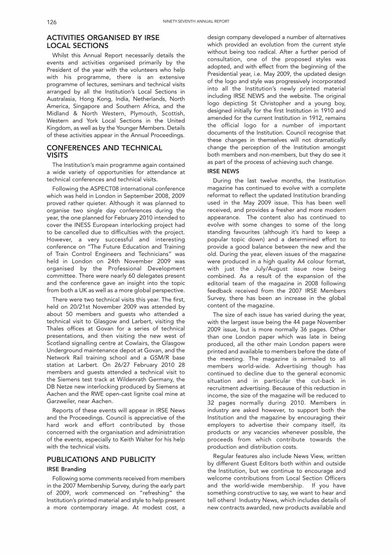
ACTIVITIES ORGANISED BY IRSELOCAL SECTIONS
Whilst this Annual Report necessarily details theevents and activities organised primarily by thePresident of the year with the volunteers who helpwith his programme, there is an extensiveprogramme of lectures, seminars and technical visitsarranged by all the Institution’s Local Sections inAustralasia, Hong Kong, India, Netherlands, NorthAmerica, Singapore and Southern Africa, and theMidland & North Western, Plymouth, Scottish,Western and York Local Sections in the UnitedKingdom, as well as by the Younger Members. Detailsof these activities appear in the Annual Proceedings.
CONFERENCES AND TECHNICALVISITS
The Institution’s main programme again containeda wide variety of opportunities for attendance attechnical conferences and technical visits.
Following the ASPECT08 international conferencewhich was held in London in September 2008, 2009proved rather quieter. Although it was planned toorganise two single day conferences during theyear, the one planned for February 2010 intended tocover the INESS European interlocking project hadto be cancelled due to difficulties with the project.However, a very successful and interestingconference on “The Future Education and Trainingof Train Control Engineers and Technicians” washeld in London on 24th November 2009 wasorganised by the Professional Developmentcommittee. There were nearly 60 delegates presentand the conference gave an insight into the topicfrom both a UK as well as a more global perspective.
There were two technical visits this year. The first,held on 20/21st November 2009 was attended byabout 50 members and guests who attended atechnical visit to Glasgow and Larbert, visiting theThales offices at Govan for a series of technicalpresentations, and then visiting the new west ofScotland signalling centre at Cowlairs, the GlasgowUnderground maintenance depot at Govan, and theNetwork Rail training school and a GSM/R basestation at Larbert. On 26/27 February 2010 28members and guests attended a technical visit tothe Siemens test track at Wildenrath Germany, theDB Netze new interlocking produced by Siemens atAachen and the RWE open-cast lignite coal mine atGarzweiler, near Aachen.
Reports of these events will appear in IRSE Newsand the Proceedings. Council is appreciative of thehard work and effort contributed by thoseconcerned with the organisation and administrationof the events, especially to Keith Walter for his helpwith the technical visits.
PUBLICATIONS AND PUBLICITYIRSE Branding
Following some comments received from membersin the 2007 Membership Survey, during the early partof 2009, work commenced on “refreshing” theInstitution’s printed material and style to help presenta more contemporary image. At modest cost, a
design company developed a number of alternativeswhich provided an evolution from the current stylewithout being too radical. After a further period ofconsultation, one of the proposed styles wasadopted, and with effect from the beginning of thePresidential year, i.e. May 2009, the updated designof the logo and style was progressively incorporatedinto all the Institution’s newly printed materialincluding IRSE NEWS and the website. The originallogo depicting St Christopher and a young boy,designed initially for the first Institution in 1910 andamended for the current Institution in 1912, remainsthe official logo for a number of importantdocuments of the Institution. Council recognise thatthese changes in themselves will not dramaticallychange the perception of the Institution amongstboth members and non-members, but they do see itas part of the process of achieving such change.
IRSE NEWS
During the last twelve months, the Institutionmagazine has continued to evolve with a completereformat to reflect the updated Institution brandingused in the May 2009 issue. This has been wellreceived, and provides a fresher and more modernappearance. The content also has continued toevolve with some changes to some of the longstanding favourites (although it’s hard to keep apopular topic down) and a determined effort toprovide a good balance between the new and theold. During the year, eleven issues of the magazinewere produced in a high quality A4 colour format,with just the July/August issue now beingcombined. As a result of the expansion of theeditorial team of the magazine in 2008 followingfeedback received from the 2007 IRSE MembersSurvey, there has been an increase in the globalcontent of the magazine.
The size of each issue has varied during the year,with the largest issue being the 44 page November2009 issue, but is more normally 36 pages. Otherthan one London paper which was late in beingproduced, all the other main London papers wereprinted and available to members before the date ofthe meeting. The magazine is airmailed to allmembers world-wide. Advertising though hascontinued to decline due to the general economicsituation and in particular the cut-back inrecruitment advertising. Because of this reduction inincome, the size of the magazine will be reduced to32 pages normally during 2010. Members inindustry are asked however, to support both theInstitution and the magazine by encouraging theiremployers to advertise their company itself, itsproducts or any vacancies whenever possible, theproceeds from which contribute towards theproduction and distribution costs.
Regular features also include News View, writtenby different Guest Editors both within and outsidethe Institution, but we continue to encourage andwelcome contributions from Local Section Officersand the world-wide membership. If you havesomething constructive to say, we want to hear andtell others! Industry News, which includes details ofnew contracts awarded, new products available and
NINETY-SEVENTH ANNUAL REPORT126
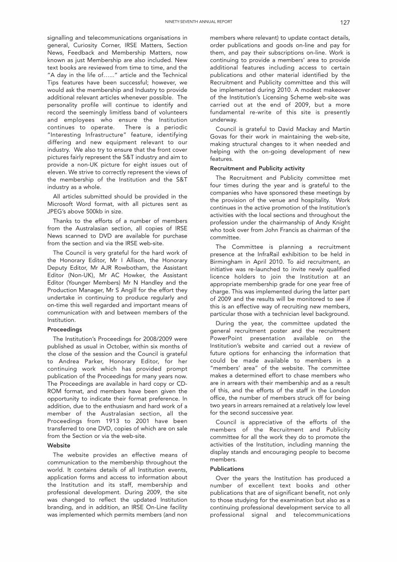
signalling and telecommunications organisations ingeneral, Curiosity Corner, IRSE Matters, SectionNews, Feedback and Membership Matters, nowknown as just Membership are also included. Newtext books are reviewed from time to time, and the“A day in the life of…...” article and the TechnicalTips features have been successful; however, wewould ask the membership and Industry to provideadditional relevant articles whenever possible. Thepersonality profile will continue to identify andrecord the seemingly limitless band of volunteersand employees who ensure the Institutioncontinues to operate. There is a periodic“Interesting Infrastructure” feature, identifyingdiffering and new equipment relevant to ourindustry. We also try to ensure that the front coverpictures fairly represent the S&T industry and aim toprovide a non-UK picture for eight issues out ofeleven. We strive to correctly represent the views ofthe membership of the Institution and the S&Tindustry as a whole.
All articles submitted should be provided in theMicrosoft Word format, with all pictures sent asJPEG’s above 500kb in size.
Thanks to the efforts of a number of membersfrom the Australasian section, all copies of IRSENews scanned to DVD are available for purchasefrom the section and via the IRSE web-site.
The Council is very grateful for the hard work ofthe Honorary Editor, Mr I Allison, the HonoraryDeputy Editor, Mr AJR Rowbotham, the AssistantEditor (Non-UK), Mr AC Howker, the AssistantEditor (Younger Members) Mr N Handley and theProduction Manager, Mr S Angill for the effort theyundertake in continuing to produce regularly andon-time this well regarded and important means ofcommunication with and between members of theInstitution.
Proceedings
The Institution’s Proceedings for 2008/2009 werepublished as usual in October, within six months ofthe close of the session and the Council is gratefulto Andrea Parker, Honorary Editor, for hercontinuing work which has provided promptpublication of the Proceedings for many years now.The Proceedings are available in hard copy or CD-ROM format, and members have been given theopportunity to indicate their format preference. Inaddition, due to the enthusiasm and hard work of amember of the Australasian section, all theProceedings from 1913 to 2001 have beentransferred to one DVD, copies of which are on salefrom the Section or via the web-site.
Website
The website provides an effective means ofcommunication to the membership throughout theworld. It contains details of all Institution events,application forms and access to information aboutthe Institution and its staff, membership andprofessional development. During 2009, the sitewas changed to reflect the updated Institutionbranding, and in addition, an IRSE On-Line facilitywas implemented which permits members (and non
members where relevant) to update contact details,order publications and goods on-line and pay forthem, and pay their subscriptions on-line. Work iscontinuing to provide a members’ area to provideadditional features including access to certainpublications and other material identified by theRecruitment and Publicity committee and this willbe implemented during 2010. A modest makeoverof the Institution’s Licensing Scheme web-site wascarried out at the end of 2009, but a morefundamental re-write of this site is presentlyunderway.
Council is grateful to David Mackay and MartinGovas for their work in maintaining the web-site,making structural changes to it when needed andhelping with the on-going development of newfeatures.
Recruitment and Publicity activity
The Recruitment and Publicity committee metfour times during the year and is grateful to thecompanies who have sponsored these meetings bythe provision of the venue and hospitality. Workcontinues in the active promotion of the Institution’sactivities with the local sections and throughout theprofession under the chairmanship of Andy Knightwho took over from John Francis as chairman of thecommittee.
The Committee is planning a recruitmentpresence at the InfraRail exhibition to be held inBirmingham in April 2010. To aid recruitment, aninitiative was re-launched to invite newly qualifiedlicence holders to join the Institution at anappropriate membership grade for one year free ofcharge. This was implemented during the latter partof 2009 and the results will be monitored to see ifthis is an effective way of recruiting new members,particular those with a technician level background.
During the year, the committee updated thegeneral recruitment poster and the recruitmentPowerPoint presentation available on theInstitution’s website and carried out a review offuture options for enhancing the information thatcould be made available to members in a“members’ area” of the website. The committeemakes a determined effort to chase members whoare in arrears with their membership and as a resultof this, and the efforts of the staff in the Londonoffice, the number of members struck off for beingtwo years in arrears remained at a relatively low levelfor the second successive year.
Council is appreciative of the efforts of themembers of the Recruitment and Publicitycommittee for all the work they do to promote theactivities of the Institution, including manning thedisplay stands and encouraging people to becomemembers.
Publications
Over the years the Institution has produced anumber of excellent text books and otherpublications that are of significant benefit, not onlyto those studying for the examination but also as acontinuing professional development service to allprofessional signal and telecommunications
127NINETY-SEVENTH ANNUAL REPORT
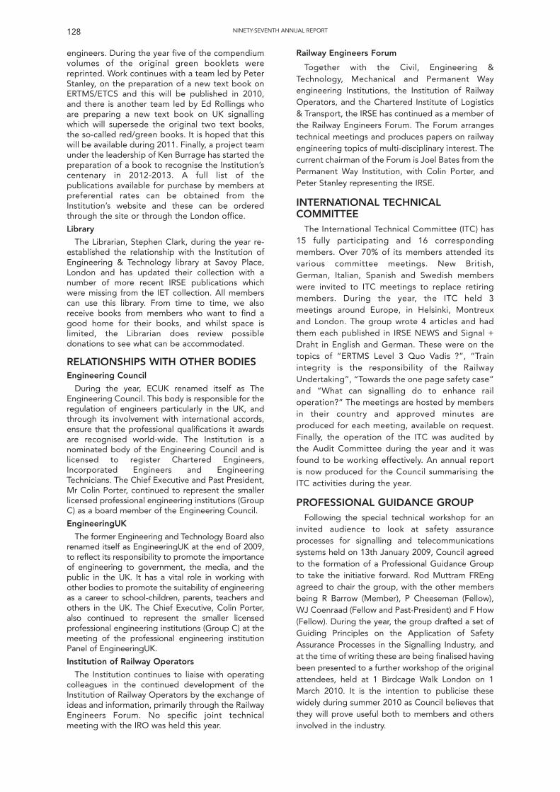
engineers. During the year five of the compendiumvolumes of the original green booklets werereprinted. Work continues with a team led by PeterStanley, on the preparation of a new text book onERTMS/ETCS and this will be published in 2010,and there is another team led by Ed Rollings whoare preparing a new text book on UK signallingwhich will supersede the original two text books,the so-called red/green books. It is hoped that thiswill be available during 2011. Finally, a project teamunder the leadership of Ken Burrage has started thepreparation of a book to recognise the Institution’scentenary in 2012-2013. A full list of thepublications available for purchase by members atpreferential rates can be obtained from theInstitution’s website and these can be orderedthrough the site or through the London office.
Library
The Librarian, Stephen Clark, during the year re-established the relationship with the Institution ofEngineering & Technology library at Savoy Place,London and has updated their collection with anumber of more recent IRSE publications whichwere missing from the IET collection. All memberscan use this library. From time to time, we alsoreceive books from members who want to find agood home for their books, and whilst space islimited, the Librarian does review possibledonations to see what can be accommodated.
RELATIONSHIPS WITH OTHER BODIESEngineering Council
During the year, ECUK renamed itself as TheEngineering Council. This body is responsible for theregulation of engineers particularly in the UK, andthrough its involvement with international accords,ensure that the professional qualifications it awardsare recognised world-wide. The Institution is anominated body of the Engineering Council and islicensed to register Chartered Engineers,Incorporated Engineers and EngineeringTechnicians. The Chief Executive and Past President,Mr Colin Porter, continued to represent the smallerlicensed professional engineering institutions (GroupC) as a board member of the Engineering Council.
EngineeringUK
The former Engineering and Technology Board alsorenamed itself as EngineeringUK at the end of 2009,to reflect its responsibility to promote the importanceof engineering to government, the media, and thepublic in the UK. It has a vital role in working withother bodies to promote the suitability of engineeringas a career to school-children, parents, teachers andothers in the UK. The Chief Executive, Colin Porter,also continued to represent the smaller licensedprofessional engineering institutions (Group C) at themeeting of the professional engineering institutionPanel of EngineeringUK.
Institution of Railway Operators
The Institution continues to liaise with operatingcolleagues in the continued development of theInstitution of Railway Operators by the exchange ofideas and information, primarily through the RailwayEngineers Forum. No specific joint technicalmeeting with the IRO was held this year.
Railway Engineers Forum
Together with the Civil, Engineering &Technology, Mechanical and Permanent Wayengineering Institutions, the Institution of RailwayOperators, and the Chartered Institute of Logistics& Transport, the IRSE has continued as a member ofthe Railway Engineers Forum. The Forum arrangestechnical meetings and produces papers on railwayengineering topics of multi-disciplinary interest. Thecurrent chairman of the Forum is Joel Bates from thePermanent Way Institution, with Colin Porter, andPeter Stanley representing the IRSE.
INTERNATIONAL TECHNICALCOMMITTEE
The International Technical Committee (ITC) has15 fully participating and 16 correspondingmembers. Over 70% of its members attended itsvarious committee meetings. New British,German, Italian, Spanish and Swedish memberswere invited to ITC meetings to replace retiringmembers. During the year, the ITC held 3meetings around Europe, in Helsinki, Montreuxand London. The group wrote 4 articles and hadthem each published in IRSE NEWS and Signal +Draht in English and German. These were on thetopics of “ERTMS Level 3 Quo Vadis ?”, “Trainintegrity is the responsibility of the RailwayUndertaking”, “Towards the one page safety case”and “What can signalling do to enhance railoperation?” The meetings are hosted by membersin their country and approved minutes areproduced for each meeting, available on request.Finally, the operation of the ITC was audited bythe Audit Committee during the year and it wasfound to be working effectively. An annual reportis now produced for the Council summarising theITC activities during the year.
PROFESSIONAL GUIDANCE GROUPFollowing the special technical workshop for an
invited audience to look at safety assuranceprocesses for signalling and telecommunicationssystems held on 13th January 2009, Council agreedto the formation of a Professional Guidance Groupto take the initiative forward. Rod Muttram FREngagreed to chair the group, with the other membersbeing R Barrow (Member), P Cheeseman (Fellow),WJ Coenraad (Fellow and Past-President) and F How(Fellow). During the year, the group drafted a set ofGuiding Principles on the Application of SafetyAssurance Processes in the Signalling Industry, andat the time of writing these are being finalised havingbeen presented to a further workshop of the originalattendees, held at 1 Birdcage Walk London on 1March 2010. It is the intention to publicise thesewidely during summer 2010 as Council believes thatthey will prove useful both to members and othersinvolved in the industry.
128 NINETY-SEVENTH ANNUAL REPORT
COMMITTEESThe following were appointed to serve on the
standing committees shown and the Councilextends its thanks to them for the valuable workthey undertake on behalf of the Institution:
Management Committee: Messrs PA Jenkins(Chairman), WJ Coenraad, JD Francis, MH Govas, J Haile, F Heijnen, F How, J Irwin, I Mitchell, J Poré,Mrs CL Porter, CH Porter (Secretary) and D Weedon.
Membership Committee: Mrs CL Porter(Chairman), I Bridges, BD Cowdhury, M Fenner,P Grant, R Gray, PA Jenkins, IH Mitchell, RW Penny,CH Porter (Chief Executive), G Simpson, PW Stanley, D Weedon, Ms C White (Membership &PD Manager/Secretary), and I Beaton (repEngineering Council).
Finance Committee: Messrs WJ Coenraad(Chairman), JD Francis, MH Govas (Treasurer/Secretary), F Heijnen, PA Jenkins, IH Mitchell, CH Porter (Chief Executive) and Mrs CL Porter.
Professional Development Committee:Messrs C King (Chairman), W Alexander, L Brearley,BD Chowdhury, D Cornall, I Ettle, J Joyce, K Marchand, G Wire, DN Woodland, Ms C White(Secretary) and C H Porter (Chief Executive).
Examination Committee: Messrs DN Woodland(Chairman), J Alexander, I Brown, P Darlington, P Hetherington, DA Hotchkiss, D Jones, Miss U Khaleel,A Kornas, B Lui, T Lee, C Lovelock, M Miller, S Rodgers (Secretary), RC Short, NT Smith,A Stringer, CI Weightman, CR White and Ms C White.
International Technical Committee: C Sevestre -Chairman (France), WJ Coenraad, (Netherlands), F Fabbian (Italy),I Gal (Hungary), EO Goddard (UK),G Hagelin (Sweden), F Heijnen (Germany), Y Hirao(Japan), S Hiraguri (Japan), C Kessell (UK), F Kollmannsberger (Germany), L Lochmann,(Belgium) L Matikainen (Finland), R Mattenberger(Switzerland), I McCullough (UK), I Mitchell (UK), F Montes (Spain), M Montigel (Switzerland), J Noffsinger (USA), J Poré, (France), CH Porter(IRSE), H Rochford (Secretary), C Rodriguez (Spain),A Rumsey (Canada), R Seiffert, (Switzerland), A Simmons (UK), G Simpson (UK), PW Stanley (UK),B Steyn (South Africa), J Stutzbach (Germany), P Symons (Australia), and A Zierl (Austria).
Licensing Committee: Messrs KW Burrage(Chairman), L Braithwaite, JWA Colvin, F How, P Mann, P Martell, I Maxwell, AJ Metcalfe, MD Moore, A Nattrass, MK Poole and ex officio: MH Govas (Treasurer), CH Porter (Chief Executive)and R Hobby (Licensing Registrar/Secretary).Advisors R Bell, M Watson-Walker, and FP Wiltshire.
Recruitment & Publicity Committee:Messrs A Knight (Chairman), I Allison, SJ Clark, P Eldridge (Secretary), M Glover, M Hewett, R Hobby,I Mitchell, CH Porter (Chief Executive), RH Price, AJRRowbotham, S Turner, and GF Wire.
Internal Auditors: PW Stanley (Chairman), D McKeown and RW Penny.
LOCAL SECTIONS AND YOUNGERMEMBERS
The Non-UK Sections of the Institution inAustralasia, Hong Kong, India, The Netherlands,North America, Singapore and Southern Africa, andthe Midland & North Western, Minor Railways,Plymouth, Scottish, Western and York Local Sectionsin the United Kingdom all continued to operatesuccessfully. The Sections which were newly formedin 2009, the Indian and Minor Railways Sections,started to organise lectures and visits during theirfirst year, with the Indian Section being set thechallenge of organising the 2010 InternationalTechnical Convention. Some interest has beenshown in forming a new Section in Ireland, and it willhave to be seen whether this comes to fruition overthe next few years.
The Younger Members again arranged aninteresting series of meetings during the year,commencing with a module 5 examinationpreparation day at GM Rail’s training centre in Rugbyin July 2009, and then a further day on modules 2 & 3at Signet’s training centre in Derby in August. This wasfollowed by a YM conference and visit held in York inNovember 2009, and then a half day conference andexamination review in London in January 2010.
The Council wishes to record its thanks to theOfficers, Committee members and all others in theSections, for the excellent work they undertake inorganising the meetings and other events. Theirdedication, hard work and enthusiasm, when underincreasingly heavy day-to-day work pressures, is amajor contribution to the success of the Institution.In addition, Council very much appreciates the helpand support given by many companies in facilitatingand supporting the events organised by theSections.
The Officers of the Sections were:
NON-UK
Australasian Section: Chairman, Mr J Aitken;Country Vice-President, Mr PR Symons; Vice-Chairman, Mr S Boshier; Hon Secretary & Treasurer,Mr G Willmott.
Hong Kong Section: Chairman, Mr Lai Yan Lam; Vice-Chairman, Mr Chun Pong Lung; Secretary, Mr Yuen Fat Sung; Treasurer, Kenny, Tim Yau Ng.
Indian Section: Chairman, Mr KK Bajpeyee; Vice-Chairman, Mr S Lahiri; Secretary/Treasurer, Mr A Gupta.
Netherlands Section: Chairman, Mr J Oonincx; Vice-Chairman, Mr P Musters; Treasurer, Mr P Otten;Secretary, Mr A Förrer.
North American Section: Chairman, Mr D Thurston; Vice-Chairman, Mr K Bisset; Secretary, Mr G Young;Country Vice-President, Mr WJ Scheerer.
Singaporean Section: Chairman, Mr M Appleyard; Vice-Chairman, Mr R Shield; Secretary/Treasurer, Mr I Tomlins.
Southern African Section: Chairman, Mr B van derMerwe; Vice-Chairman, Mr B Ostendorf; HonSecretary, Mr P Meyer; Hon Treasurer, Mr JC van dePol; Country Vice-President, Mr GB Paverd.
129NINETY-SEVENTH ANNUAL REPORT
UK
Midland & North Western Section: Chairman, Mr G Hill; Vice-Chairman, Mr P Duguay; HonSecretary, Mr W Redfern; Hon Treasurer, Mr C Williams.
Minor Railways: Chairman, Mr I Allison; Secretary, Mr M Huibers; Treasurer, Mr T Hodgson.
Plymouth Section: Chairman, Mr A Lovett; Vice-Chairman, Mr R Nettleton; Hon Secretary &Treasurer, Mr D Came.
Scottish Section: Chairman, Mrs L Hunter; Vice-Chairman, Mr C Hourston; Hon Secretary, Mr S Wright; Hon Treasurer, Mr B McKendrick.
Western Section: Chairman, Mr P Duggan; Vice-Chairman, M Peters; Treasurer, Mr A Scarisbrick;Hon Secretary, Mr M Peters.
York Section: Chairman, Mr J Maw; Vice-Chairman, Mr D Gillanders; Hon Secretary, Mr J Maw; HonTreasurer, Mr AP Smith.
Younger Members: Chairman, Mrs L Hunter; Hon Secretary, Mr M Fenner; Hon Treasurer Mr A Whitton.
ACKNOWLEDGEMENTSAs I said at the beginning of the report, it was a
strange start to the year but I was wonderfullysupported by Colin Porter and the staff of the IRSEenabling me to fill the gap left by Alan quickly. Iwould also like to thank Invensys for making all thetravel needed for my activities as President possibleand for sponsoring some of the activities. Last butnot least I would like to thank my wife Alphonsinefor being at my side in many occasions and forhaving to live with me not being home on so manyoccasions.
Frans HeijnenPresident1 Birdcage WalkWestminsterLondon, UK March 2010
130 NINETY-SEVENTH ANNUAL REPORT
The Chairman welcomed members to the AnnualGeneral Meeting.
PREVIOUS MINUTES AND AUDITOR'SREPORT
It was proposed by Mr K W Burrage (Hon Fellow)and seconded by Mr C Kessell (Hon Fellow) andcarried that the minutes of the 96th Annual GeneralMeeting held on 24th April, 2009, be taken as readand they were signed by the Chairman.
The Chairman then asked the Secretary to readthe Report of the Auditor, which he did.
ANNUAL REPORT AND ACCOUNTS,2008
The Chairman stated that the annual report andaccounts had been circulated to all membersworldwide and then at the request of the Chairman,the Institution's Treasurer, Mr M.H. Govascommented on the overall increase in theInstitutions funds due mainly to the generousbequest from Frank Hewlett, and a partial recoveryin the value of the capital investments of theInstitution. The small loss in the trading account wasprimarily due to the decline in advertising income, asituation which was continuing in the current year.The Chairman then asked whether anyone presentwished to discuss any point in the Annual Reportand Accounts. No one did.
There being no questions it was proposed by theChairman, seconded by Mr A Simmons (Fellow) andcarried that the Annual Report and Accounts for theyear 2009 as presented be adopted. The Chairmanthen put the motion to the meeting which wascarried with none against.
COMPOSITION OF COUNCIL, 2010-2011
The Chairman announced that as a result of theballot that had been held, the Institution's Councilfor the year 2010-2011 would be composed asunder: -
President: P A Jenkins
Vice Presidents: Mrs C L Porter
F How
Members of Council from class of Fellow
K W Burrage Dr A F Rumsey
J Irwin C Sevestre
I Mitchell A Simmons
Miss A Parker G J Simpson
C R Page D N Weedon
Members of Council from Class of Member
J J Aitken P Grant
I Allison A S Kornas
B Chowdhury Dr D N Woodland
Members of Council from Class of AssociateMember
S Eastmond Miss L C Simón
The Chairman then proposed a vote of thanks tothe following retiring members of Council for theirservice to the Institution;
Jacques Poré, Past President, 13 years serviceon Council
Nick Wright, 7 years service on Council
The meeting showed its appreciation and thankswith applause
AUDITORThe Chairman announced that the Institution's
Auditors, Ian Katté & Co., of Addlestone, Surrey,had indicated their willingness to continue in thiscapacity for a further year and it was therecommendation of the Council that they should doso. It was proposed by Mr. J Tilley (Fellow),seconded by Mr. E O Goddard (Hon Fellow) andcarried with none against that Ian Katté &Co. beappointed Auditors to the Institution for the year2010.
OTHER BUSINESS.AWARDS
Dell award
The Dell award is made annually under a bequestof the late Robert Dell OBE (Past President). It isawarded to a member of the Institution employedby London Underground Ltd (or its successorbodies) for achievement of a high standard of skill inthe science and application of railway signalling. Theaward takes the form of a plaque with a uniquelydesigned shield being added each year with therecipient’s name engraved on it and a cheque for£300 to spend as the recipient wishes.
The winner of this year’s Dell award was named asPeter Clifford of Tube Lines Ltd and the Presidentpresented Mr Clifford with the Dell award toapplause.
Thorrowgood Scholarship
The Thorrowgood scholarship is awarded annuallyunder a bequest of the late W J Thorrowgood (PastPresident) to assist the development of a youngengineer employed in the signalling and
131
Ninety-Seventh Annual General Meeting
Minutes of the Ninety-Seventh Annual General Meetingheld at 1 Birdcage Walk, London, SW1
on Friday 23rd April 2010
The President, Mr F Heijnen, in the Chair
telecommunications field of engineering and takesthe form of an engraved medallion and a cheque for£1500 to be used to finance a study tour of railwaysignalling installations or signalling manufacturingfacilities. The award is made, subject to satisfactoryinterview, to the Institution young member attainingat least a pass with credit in four modules in theInstitution’s examination.
The winner of the 2009 Thorrowgood Scholarshipwas Dan Heeley, from Network Rail and thePresident presented Mr Heeley with his Scholarshipmedallion amidst applause.
Election of Honorary Fellows
The Chief Executive then announced that theCouncil had decided to elect the following tobecome Honorary Fellows of the Institution inrecognition of their long and distinguished serviceto the profession and to the IRSE.
Derek Hotchkiss, Fellow, UK
Graham Paverd, Fellow, from South Africa
Jan Oonincx, Fellow, from the Netherlands
The Lord Denis Tunnicliffe CBE, formerCompanion, UK
Geoff Wilmott, Associate, from Australia
Lord Tunnicliffe was unable to be present, but theChief Executive read out a letter he had sentexpressing his pleasure at being elected anHonorary Fellow. As Derek Hotchkiss was present,he was invited to come forward to receive his newcertificate of membership from the President. TheChief Executive commented that Derek had beenawarded the first Thorrowgood Scholarshipmedallion at the AGM held in 1960, 50 years ago,and had been a member of the examinationcommittee since 1968. The meeting showed theirapproval of his award with prolonged applause.
PRESENTATION OF FINAL DRAFT OFETCS TEXTBOOK
Mr Peter Stanley then came forward to presentthe President with a copy of the final draft of thenew IRSE text book “ETCS for Engineers.” Finalediting and printing would take place during thesummer to achieve a publication date of 1September 2010.
NEWLY ELECTED PRESIDENT TAKESTHE CHAIR
The Chairman, Mr F Heijnen, then invited thenewly elected President, Mr Paul Jenkins, to takethe Chair, which he did amidst applause, and MrHeijnen invested him with the Presidential Chain ofoffice.
VOTE OF THANKS TO THE PASTPRESIDENT
Having taken the Chair, Mr Jenkins thanked MrHeijnen for his excellent Presidential year andmembers showed their appreciation with prolongedapplause.
PRESIDENTIAL ADDRESSThe President, Mr Paul Jenkins then delivered his
Inaugural Address a copy of which will appear inIRSE News and in the Proceedings.
A vote of thanks to him for his Address wasproposed by Mr C Kessell (Hon Fellow) who alsogave some background on the President’s initialappointment to British Rail, and this vote of thankswas carried with applause.
The President then declared the Annual GeneralMeeting closed.
NINETY-SEVENTH ANNUAL GENERAL MEETING132
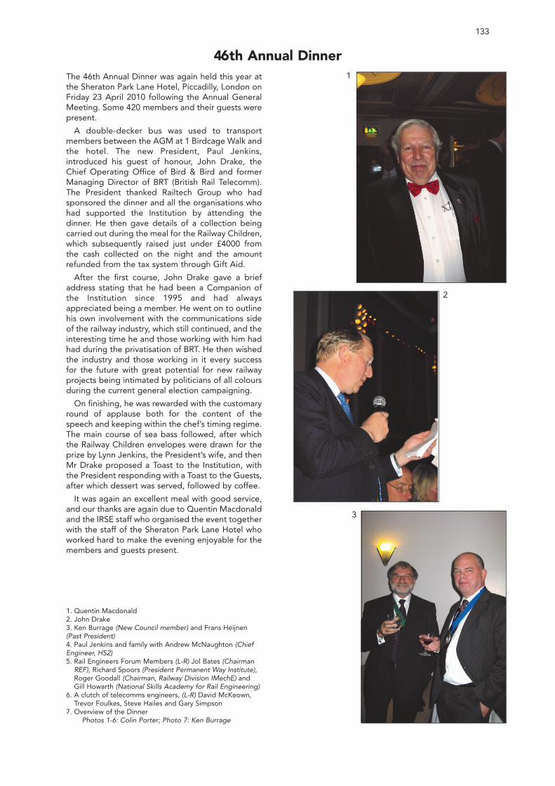
133
46th Annual DinnerThe 46th Annual Dinner was again held this year atthe Sheraton Park Lane Hotel, Piccadilly, London onFriday 23 April 2010 following the Annual GeneralMeeting. Some 420 members and their guests werepresent.
A double-decker bus was used to transportmembers between the AGM at 1 Birdcage Walk andthe hotel. The new President, Paul Jenkins,introduced his guest of honour, John Drake, theChief Operating Office of Bird & Bird and formerManaging Director of BRT (British Rail Telecomm).The President thanked Railtech Group who hadsponsored the dinner and all the organisations whohad supported the Institution by attending thedinner. He then gave details of a collection beingcarried out during the meal for the Railway Children,which subsequently raised just under £4000 fromthe cash collected on the night and the amountrefunded from the tax system through Gift Aid.
After the first course, John Drake gave a briefaddress stating that he had been a Companion ofthe Institution since 1995 and had alwaysappreciated being a member. He went on to outlinehis own involvement with the communications sideof the railway industry, which still continued, and theinteresting time he and those working with him hadhad during the privatisation of BRT. He then wishedthe industry and those working in it every successfor the future with great potential for new railwayprojects being intimated by politicians of all coloursduring the current general election campaigning.
On finishing, he was rewarded with the customaryround of applause both for the content of thespeech and keeping within the chef’s timing regime.The main course of sea bass followed, after whichthe Railway Children envelopes were drawn for theprize by Lynn Jenkins, the President’s wife, and thenMr Drake proposed a Toast to the Institution, withthe President responding with a Toast to the Guests,after which dessert was served, followed by coffee.
It was again an excellent meal with good service,and our thanks are again due to Quentin Macdonaldand the IRSE staff who organised the event togetherwith the staff of the Sheraton Park Lane Hotel whoworked hard to make the evening enjoyable for themembers and guests present.
1. Quentin Macdonald2. John Drake3. Ken Burrage (New Council member) and Frans Heijnen(Past President)4. Paul Jenkins and family with Andrew McNaughton (ChiefEngineer, HS2)5. Rail Engineers Forum Members (L-R) Jol Bates (Chairman
REF), Richard Spoors (President Permanent Way Institute),Roger Goodall (Chairman, Railway Division IMechE) andGill Howarth (National Skills Academy for Rail Engineering)
6. A clutch of telecomms engineers, (L-R) David McKeown,Trevor Foulkes, Steve Hailes and Gary Simpson
7. Overview of the DinnerPhotos 1-6: Colin Porter; Photo 7: Ken Burrage
1
2
3
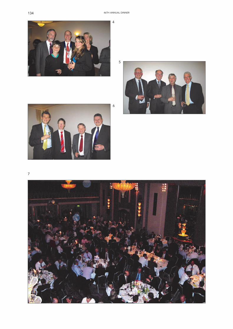
134 46TH ANNUAL DINNER
4
5
6
7
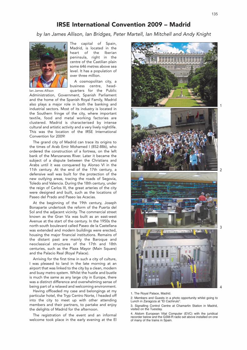
135
The capital of Spain,Madrid, is located in theheart of the Iberianpeninsula, right in thecentre of the Castilian plainsome 646 metres above sealevel. It has a population ofover three million.
A cosmopolitan city, abusiness centre, head-quarters for the Public
Administration, Government, Spanish Parliamentand the home of the Spanish Royal Family, Madridalso plays a major role in both the banking andindustrial sectors. Most of its industry is located inthe Southern fringe of the city, where importanttextile, food and metal working factories areclustered. Madrid is characterised by intensecultural and artistic activity and a very lively nightlife.This was the location of the IRSE InternationalConvention for 2009!
The grand city of Madrid can trace its origins tothe times of Arab Emir Mohamed I (852-886), whoordered the construction of a fortress, on the leftbank of the Manzanares River. Later it became thesubject of a dispute between the Christians andArabs until it was conquered by Alonso VI in the11th century. At the end of the 17th century, adefensive wall was built for the protection of thenew outlying areas, tracing the roads of Segovia,Toledo and Valencia. During the 18th century, underthe reign of Carlos III, the great arteries of the citywere designed and built, such as the locations ofPaseo del Prado and Paseo las Acacias.
At the beginning of the 19th century, JosephBonaparte undertook the reform of the Puerta delSol and the adjacent vicinity. The commercial streetknown as the Gran Vía was built as an east-westAvenue at the start of the century. In the 1950s thenorth-south boulevard called Paseo de la Castellanawas extended and modern buildings were erected,housing the major financial institutions. Remains ofthe distant past are mainly the Baroque andneoclassical structures of the 17th and 18thcenturies, such as the Plaza Mayor (Main Square)and the Palacio Real (Royal Palace).
Arriving for the first time in such a city of culture,I was pleased to land in the late morning at anairport that was linked to the city by a clean, modernand busy metro system. Whilst the hustle and bustleis much the same as any large city in Europe, therewas a distinct difference and overwhelming sense ofbeing part of a relaxed and welcoming environment.
Having offloaded my case and belongings at myparticular hotel, the Tryp Centro Norte, I headed offinto the city to meet up with other attendingmembers and their partners, to partake and enjoythe delights of Madrid for the afternoon.
The registration of the event and an informalwelcome took place in the early evening at the El
IRSE International Convention 2009 – Madridby Ian James Allison, Ian Bridges, Peter Martell, Ian Mitchell and Andy Knight
Ian James Allison
1. The Royal Palace, Madrid.2. Members and Guests in a photo opportunity whilst going toLunch in Zaragoza at “El Cachirulo”.3. Signalling Control Centre at Chamartin Station in Madrid,visited on the Tuesday.4. Alstom European Vital Computer (EVC) with the juridicalrecorder below and the GSM-R radio set above installed on oneof many of the trains in Spain.
1
2
3
4
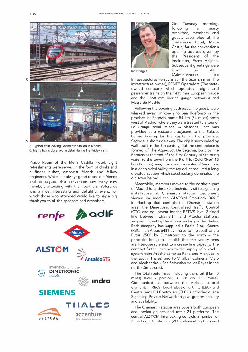
Prado Room of the Melia Castilla Hotel. Lightrefreshments were served in the form of drinks anda finger buffet, amongst friends and fellowengineers. Whilst it is always good to see old friendsand colleagues, this convention saw many newmembers attending with their partners. Before uswas a most interesting and delightful event, forwhich those who attended would like to say a bigthank you to all the sponsors and organisers.
IRSE INTERNATIONAL CONVENTION 2009136
On Tuesday morning,following a heartybreakfast, members andguests assembled at theconference hotel, MeliaCastle, for the convention’sopening address given bythe President of theInstitution, Frans Heijnen.Subsequent greetings weregiven by ADIF(Administrador de
Infraestructuras Ferroviarias - the Spanish main lineinfrastructure owner), RENFE Operadora (The state-owned company which operates freight andpassenger trains on the 1435 mm European gaugeand the 1668 mm Iberian gauge networks) andMetro de Madrid.
Following the opening addresses, the guests werewhisked away by coach to San Ildefonso in theprovince of Segovia, some 54 km (34 miles) northwest of Madrid, where they were treated to a tour ofLa Granja Royal Palace. A pleasant lunch wasprovided at a restaurant adjacent to the Palace,before leaving for the capital of the province,Segovia, a short ride away. The city is surrounded bywalls built in the 8th century, but the centrepiece isformed of The Aqueduct De Segovia, built by theRomans at the end of the First Century AD to bringwater to the town from the Río Frío (Cold River) 18km (12 miles) away. Because the centre of Segovia isin a deep sided valley, the aqueduct required a longelevated section which spectacularly dominates theold town below.
Meanwhile, members moved to the northern partof Madrid to undertake a technical visit to signallinginstallations at Chamartin station. Equipmentviewed included the ALSTOM Smartlock 300-Zinterlocking that controls the Chamartin stationarea, the Dimetronic Centralised Traffic Control(CTC) and equipment for the ERTMS level 2 fittedline between Chamartin and Atocha stations,supplied in part by Dimetronic and in part by Thales.Each company has supplied a Radio Block Centre(RBC) – an Altrac 6481 by Thales to the south and aFutur 2500 by Dimetronic to the north – theprinciples being to establish that the two systemsare interoperable and to increase line capacity. Thecontract further extends to the supply of a level 1system from Atocha as far as Parla and Aranjuez inthe south (Thales) and to Villalba, Colmenar Viejoand Alcobendas – San Sebastián de los Reyes in thenorth (Dimetronic).
The total route miles, including the short 8 km (5miles) level 2 portion, is 178 km (111 miles).Communications between the various controlelements – RBCs, Local Electronic Units (LEU) andCentralised LEU Controllers (CLC) is provided over aSignalling Private Network to give greater securityand availability.
The Chamartin station area covers both Europeanand Iberian gauges and totals 21 platforms. Thecentral ALSTOM interlocking controls a number ofZone Logic Controllers (ZLC), eliminating the need
5. Typical train leaving Chamartin Station in Madrid.6. Metro trains observed in detail during the Friday visit.
5
6
Ian Bridges
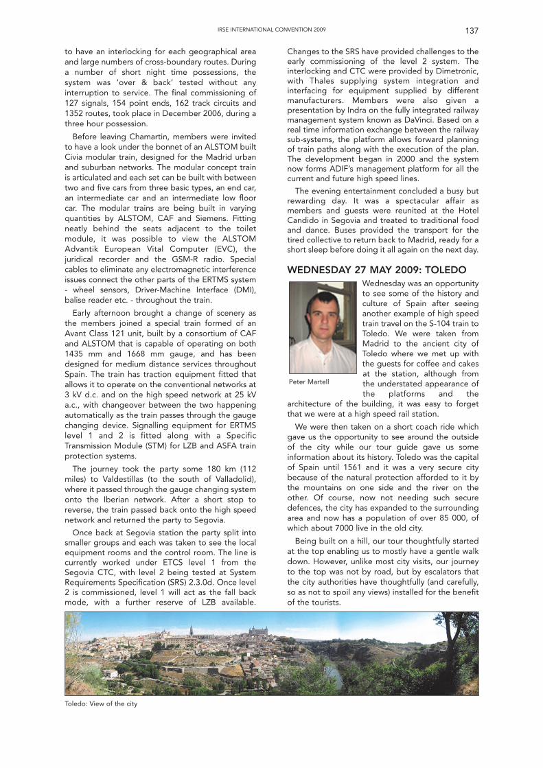
to have an interlocking for each geographical areaand large numbers of cross-boundary routes. Duringa number of short night time possessions, thesystem was ‘over & back’ tested without anyinterruption to service. The final commissioning of127 signals, 154 point ends, 162 track circuits and1352 routes, took place in December 2006, during athree hour possession.
Before leaving Chamartin, members were invitedto have a look under the bonnet of an ALSTOM builtCivia modular train, designed for the Madrid urbanand suburban networks. The modular concept trainis articulated and each set can be built with betweentwo and five cars from three basic types, an end car,an intermediate car and an intermediate low floorcar. The modular trains are being built in varyingquantities by ALSTOM, CAF and Siemens. Fittingneatly behind the seats adjacent to the toiletmodule, it was possible to view the ALSTOMAdvantik European Vital Computer (EVC), thejuridical recorder and the GSM-R radio. Specialcables to eliminate any electromagnetic interferenceissues connect the other parts of the ERTMS system- wheel sensors, Driver-Machine Interface (DMI),balise reader etc. - throughout the train.
Early afternoon brought a change of scenery asthe members joined a special train formed of anAvant Class 121 unit, built by a consortium of CAFand ALSTOM that is capable of operating on both1435 mm and 1668 mm gauge, and has beendesigned for medium distance services throughoutSpain. The train has traction equipment fitted thatallows it to operate on the conventional networks at3 kV d.c. and on the high speed network at 25 kVa.c., with changeover between the two happeningautomatically as the train passes through the gaugechanging device. Signalling equipment for ERTMSlevel 1 and 2 is fitted along with a SpecificTransmission Module (STM) for LZB and ASFA trainprotection systems.
The journey took the party some 180 km (112miles) to Valdestillas (to the south of Valladolid),where it passed through the gauge changing systemonto the Iberian network. After a short stop toreverse, the train passed back onto the high speednetwork and returned the party to Segovia.
Once back at Segovia station the party split intosmaller groups and each was taken to see the localequipment rooms and the control room. The line iscurrently worked under ETCS level 1 from theSegovia CTC, with level 2 being tested at SystemRequirements Specification (SRS) 2.3.0d. Once level2 is commissioned, level 1 will act as the fall backmode, with a further reserve of LZB available.
IRSE INTERNATIONAL CONVENTION 2009 137
Changes to the SRS have provided challenges to theearly commissioning of the level 2 system. Theinterlocking and CTC were provided by Dimetronic,with Thales supplying system integration andinterfacing for equipment supplied by differentmanufacturers. Members were also given apresentation by Indra on the fully integrated railwaymanagement system known as DaVinci. Based on areal time information exchange between the railwaysub-systems, the platform allows forward planningof train paths along with the execution of the plan.The development began in 2000 and the systemnow forms ADIF’s management platform for all thecurrent and future high speed lines.
The evening entertainment concluded a busy butrewarding day. It was a spectacular affair asmembers and guests were reunited at the HotelCandido in Segovia and treated to traditional foodand dance. Buses provided the transport for thetired collective to return back to Madrid, ready for ashort sleep before doing it all again on the next day.
WEDNESDAY 27 MAY 2009: TOLEDOWednesday was an opportunityto see some of the history andculture of Spain after seeinganother example of high speedtrain travel on the S-104 train toToledo. We were taken fromMadrid to the ancient city ofToledo where we met up withthe guests for coffee and cakesat the station, although fromthe understated appearance ofthe platforms and the
architecture of the building, it was easy to forgetthat we were at a high speed rail station.
We were then taken on a short coach ride whichgave us the opportunity to see around the outsideof the city while our tour guide gave us someinformation about its history. Toledo was the capitalof Spain until 1561 and it was a very secure citybecause of the natural protection afforded to it bythe mountains on one side and the river on theother. Of course, now not needing such securedefences, the city has expanded to the surroundingarea and now has a population of over 85 000, ofwhich about 7000 live in the old city.
Being built on a hill, our tour thoughtfully startedat the top enabling us to mostly have a gentle walkdown. However, unlike most city visits, our journeyto the top was not by road, but by escalators thatthe city authorities have thoughtfully (and carefully,so as not to spoil any views) installed for the benefitof the tourists.
Peter Martell
Toledo: View of the city
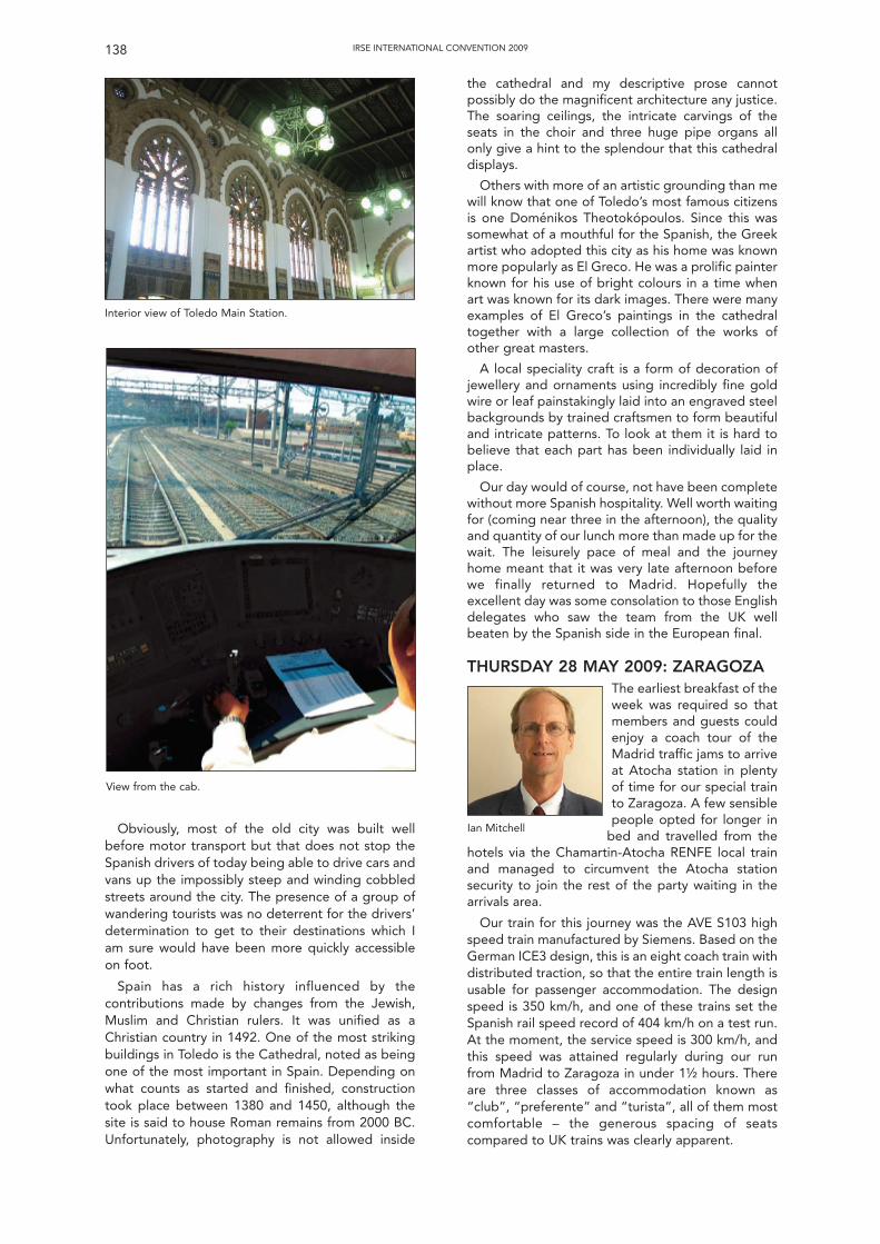
Obviously, most of the old city was built wellbefore motor transport but that does not stop theSpanish drivers of today being able to drive cars andvans up the impossibly steep and winding cobbledstreets around the city. The presence of a group ofwandering tourists was no deterrent for the drivers’determination to get to their destinations which Iam sure would have been more quickly accessibleon foot.
Spain has a rich history influenced by thecontributions made by changes from the Jewish,Muslim and Christian rulers. It was unified as aChristian country in 1492. One of the most strikingbuildings in Toledo is the Cathedral, noted as beingone of the most important in Spain. Depending onwhat counts as started and finished, constructiontook place between 1380 and 1450, although thesite is said to house Roman remains from 2000 BC.Unfortunately, photography is not allowed inside
the cathedral and my descriptive prose cannotpossibly do the magnificent architecture any justice.The soaring ceilings, the intricate carvings of theseats in the choir and three huge pipe organs allonly give a hint to the splendour that this cathedraldisplays.
Others with more of an artistic grounding than mewill know that one of Toledo’s most famous citizensis one Doménikos Theotokópoulos. Since this wassomewhat of a mouthful for the Spanish, the Greekartist who adopted this city as his home was knownmore popularly as El Greco. He was a prolific painterknown for his use of bright colours in a time whenart was known for its dark images. There were manyexamples of El Greco’s paintings in the cathedraltogether with a large collection of the works ofother great masters.
A local speciality craft is a form of decoration ofjewellery and ornaments using incredibly fine goldwire or leaf painstakingly laid into an engraved steelbackgrounds by trained craftsmen to form beautifuland intricate patterns. To look at them it is hard tobelieve that each part has been individually laid inplace.
Our day would of course, not have been completewithout more Spanish hospitality. Well worth waitingfor (coming near three in the afternoon), the qualityand quantity of our lunch more than made up for thewait. The leisurely pace of meal and the journeyhome meant that it was very late afternoon beforewe finally returned to Madrid. Hopefully theexcellent day was some consolation to those Englishdelegates who saw the team from the UK wellbeaten by the Spanish side in the European final.
THURSDAY 28 MAY 2009: ZARAGOZAThe earliest breakfast of theweek was required so thatmembers and guests couldenjoy a coach tour of theMadrid traffic jams to arriveat Atocha station in plentyof time for our special trainto Zaragoza. A few sensiblepeople opted for longer in
bed and travelled from thehotels via the Chamartin-Atocha RENFE local trainand managed to circumvent the Atocha stationsecurity to join the rest of the party waiting in thearrivals area.
Our train for this journey was the AVE S103 highspeed train manufactured by Siemens. Based on theGerman ICE3 design, this is an eight coach train withdistributed traction, so that the entire train length isusable for passenger accommodation. The designspeed is 350 km/h, and one of these trains set theSpanish rail speed record of 404 km/h on a test run.At the moment, the service speed is 300 km/h, andthis speed was attained regularly during our runfrom Madrid to Zaragoza in under 1½ hours. Thereare three classes of accommodation known as“club”, “preferente” and “turista”, all of them mostcomfortable – the generous spacing of seatscompared to UK trains was clearly apparent.
IRSE INTERNATIONAL CONVENTION 2009138
Interior view of Toledo Main Station.
View from the cab.
Ian Mitchell
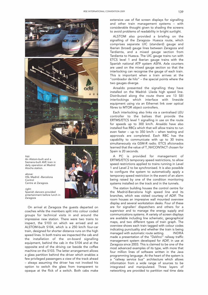
On arrival at Zaragoza the guests departed oncoaches while the members split into colour codedgroups for technical visits in and around theimpressive new station. There were two trains toinspect, the S103 on which we arrived and anALSTOM-built S104, which is a 250 km/h four-cartrain, designed for shorter distance runs on the highspeed lines. In both trains we inspected the cab andthe installation of the on-board signallingequipment, behind the cab in the S104 and at theopposite end of the driving car beside the coffeemachine on the S103. The latter arrangement allowsa glass partition behind the driver which enables afew privileged passengers a view of the track ahead– always assuming the driver has not invoked hisoption to switch the glass from transparent toopaque at the flick of a switch. Both cabs make
extensive use of flat screen displays for signallingand other train management systems – withconsiderable thought given to shading the screensto avoid problems of readability in bright sunlight.
ALSTOM also provided a briefing on thesignalling of the Zaragoza- Huesca route, whichcomprises separate UIC (standard) gauge andIberian (broad) gauge lines between Zaragoza andTardienta, and a mixed gauge section fromTardienta to Huesca. The UIC gauge trains run withETCS level 1 and Iberian gauge trains with theSpanish national ATP system ASFA. Axle countersare used on the mixed gauge section so that theinterlocking can recognise the gauge of each train.This is important when a train arrives at the“combiador de hilo” – the special points where thetwo gauges diverge.
Ansaldo presented the signalling they haveinstalled on the Madrid- Llieda high speed line.Distributed along the route there are 13 SEIinterlockings which interface with linesideequipment using via an Ethernet link over opticalfibres to MTOR object controllers.
Each interlocking also links via a centralised LEUcontroller to the balises that provide theERTMS/ETCS level 1 signalling in use on the routefor speeds up to 300 km/h. Ansaldo have alsoinstalled five RBCs which that will allow trains to runeven faster – up to 350 km/h – when testing andapprovals are completed. Each RBC has thecapability to communicate with up to 30 trainssimultaneously via GSM-R radio. ETCS aficionadoslearned that the value of T_NVCONTACT chosen forSpain is 20 seconds.
A PC is provided for management ofERTMS/ETCS temporary speed restrictions, to allowspeed restrictions applied to trains running in Level1 and Level 2 to be synchronised. It is also possibleto configure the system to automatically apply atemporary speed restriction in the event of an alarmbeing raised by one of the condition monitoringsystems installed on the track and in the tunnels.
The station building houses the control centre forthe Madrid-Barcelona high speed line and itsbranches, which was visited courtesy of ADIF. Theroom houses an impressive wall mounted overviewdisplay and several workstation desks. Four of theseare for signaller/ dispatchers and others for asupervisor and to manage the energy supply andcommunications systems. A variety of screen displaysare available including line schematic, geographicalmaps, and two different types of train graph. Theoverview shows each train tagged with colour codesindicating punctuality and whether the train is beingmanaged with automatic route setting. INDRAmade a presentation of the “DaVinci” railway trafficmanagement system developed for ADIF, in use atZaragoza since 2003. This is claimed to be one of themost advanced examples of its type, with more thatfour million lines of software written in the Javaprogramming language. At the heart of the system isa “railway service bus” architecture which allowsinformation from a wide range of sources to beintegrated and manipulated. Three layers ofnetworking are provided to partition real time data
IRSE INTERNATIONAL CONVENTION 2009 139
top:An Alstom-built and aSiemens-built AVE train indaily operation at MadridAtocha station.
above:HSL Madrid –BarcelonaControlCentre at Zaragoza.
right:Spanish dancers providedentertainment before lunch inZaragoza
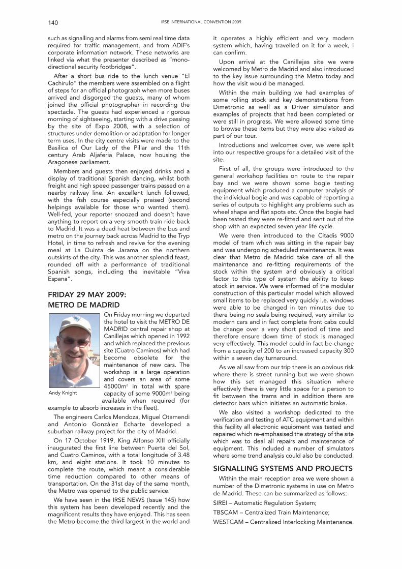
140 IRSE INTERNATIONAL CONVENTION 2009
such as signalling and alarms from semi real time datarequired for traffic management, and from ADIF’scorporate information network. These networks arelinked via what the presenter described as “mono-directional security footbridges”.
After a short bus ride to the lunch venue “ElCachirulo” the members were assembled on a flightof steps for an official photograph when more busesarrived and disgorged the guests, many of whomjoined the official photographer in recording thespectacle. The guests had experienced a rigorousmorning of sightseeing, starting with a drive passingby the site of Expo 2008, with a selection ofstructures under demolition or adaptation for longerterm uses. In the city centre visits were made to theBasilica of Our Lady of the Pillar and the 11thcentury Arab Aljaferia Palace, now housing theAragonese parliament.
Members and guests then enjoyed drinks and adisplay of traditional Spanish dancing, whilst bothfreight and high speed passenger trains passed on anearby railway line. An excellent lunch followed,with the fish course especially praised (secondhelpings available for those who wanted them).Well-fed, your reporter snoozed and doesn’t haveanything to report on a very smooth train ride backto Madrid. It was a dead heat between the bus andmetro on the journey back across Madrid to the TrypHotel, in time to refresh and revive for the eveningmeal at La Quinta de Jarama on the northernoutskirts of the city. This was another splendid feast,rounded off with a performance of traditionalSpanish songs, including the inevitable “VivaEspana”.
FRIDAY 29 MAY 2009: METRO DE MADRID
On Friday morning we departedthe hotel to visit the METRO DEMADRID central repair shop atCanillejas which opened in 1992and which replaced the previoussite (Cuatro Caminos) which hadbecome obsolete for themaintenance of new cars. Theworkshop is a large operationand covers an area of some45000m2 in total with sparecapacity of some 9000m2 being
available when required (forexample to absorb increases in the fleet).
The engineers Carlos Mendoza, Miguel Otamendiand Antonio González Echarte developed asuburban railway project for the city of Madrid.
On 17 October 1919, King Alfonso XIII officiallyinaugurated the first line between Puerta del Sol,and Cuatro Caminos, with a total longitude of 3.48km, and eight stations. It took 10 minutes tocomplete the route, which meant a considerabletime reduction compared to other means oftransportation. On the 31st day of the same month,the Metro was opened to the public service.
We have seen in the IRSE NEWS (Issue 145) howthis system has been developed recently and themagnificent results they have enjoyed. This has seenthe Metro become the third largest in the world and
it operates a highly efficient and very modernsystem which, having travelled on it for a week, Ican confirm.
Upon arrival at the Canillejas site we werewelcomed by Metro de Madrid and also introducedto the key issue surrounding the Metro today andhow the visit would be managed.
Within the main building we had examples ofsome rolling stock and key demonstrations fromDimetronic as well as a Driver simulator andexamples of projects that had been completed orwere still in progress. We were allowed some timeto browse these items but they were also visited aspart of our tour.
Introductions and welcomes over, we were splitinto our respective groups for a detailed visit of thesite.
First of all, the groups were introduced to thegeneral workshop facilities on route to the repairbay and we were shown some bogie testingequipment which produced a computer analysis ofthe individual bogie and was capable of reporting aseries of outputs to highlight any problems such aswheel shape and flat spots etc. Once the bogie hadbeen tested they were re-fitted and sent out of theshop with an expected seven year life cycle.
We were then introduced to the Citadis 9000model of tram which was sitting in the repair bayand was undergoing scheduled maintenance. It wasclear that Metro de Madrid take care of all themaintenance and re-fitting requirements of thestock within the system and obviously a criticalfactor to this type of system the ability to keepstock in service. We were informed of the modularconstruction of this particular model which allowedsmall items to be replaced very quickly i.e. windowswere able to be changed in ten minutes due tothere being no seals being required, very similar tomodern cars and in fact complete front cabs couldbe change over a very short period of time andtherefore ensure down time of stock is managedvery effectively. This model could in fact be changefrom a capacity of 200 to an increased capacity 300within a seven day turnaround.
As we all saw from our trip there is an obvious riskwhere there is street running but we were shownhow this set managed this situation whereeffectively there is very little space for a person tofit between the trams and in addition there aredetector bars which initiates an automatic brake.
We also visited a workshop dedicated to theverification and testing of ATC equipment and withinthis facility all electronic equipment was tested andrepaired which re-emphasised the strategy of the sitewhich was to deal all repairs and maintenance ofequipment. This included a number of simulatorswhere some trend analysis could also be conducted.
SIGNALLING SYSTEMS AND PROJECTSWithin the main reception area we were shown a
number of the Dimetronic systems in use on Metrode Madrid. These can be summarized as follows:
SIREI – Automatic Regulation System;
TBSCAM – Centralized Train Maintenance;
WESTCAM – Centralized Interlocking Maintenance.
Andy Knight
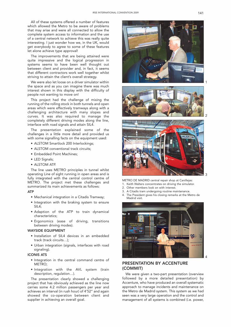
All of these systems offered a number of featureswhich allowed the Metro to be aware of problemsthat may arise and were all connected to allow thecomplete system access to information and the useof a central network to achieve this was really quiteinteresting. I just wonder how we, in the UK, wouldget everybody to agree to some of these featureslet alone achieve type approval!
The improvements that are being attained werequite impressive and the logical progression insystems seems to have been well thought outbetween client and provider and, in fact, it seemsthat different contractors work well together whilststriving to attain the client’s overall strategy.
We were also let loose on a driver simulator withinthe space and as you can imagine there was muchinterest shown in this display with the difficulty ofpeople not wanting to move on!
This project had the challenge of mixing therunning of the rolling stock in both tunnels and openareas which were effectively tramways along with achallenging architecture with many slopes andcurves. It was also required to manage thecompletely different driving modes along the line,interface with road signals and attain SIL4.
The presentation explained some of thechallenges in a little more detail and provided uswith some signalling facts on the equipment used:
• ALSTOM Smartlock 200 Interlockings;
• ALSTOM conventional track circuits;
• Embedded Point Machines;
• LED Signals;
• ALSTOM ATP.
The line uses METRO principles in tunnel whilstoperating Line of sight running in open areas and isfully integrated with the central control centre ofMETRO. The project met these challenges andsummarized its main achievements as follows:
ATP
• Mechanical integration in a Citadis Tramway;
• Integration with the braking system to ensureSIL4;
• Adaption of the ATP to train dynamicalcharacteristics;
• Ergonomics (ease of driving, transitionsbetween driving modes).
WAYSIDE EQUIPMENT
• Installation of SIL4 devices in an embeddedtrack (track circuits…);
• Urban integration (signals, interfaces with roadsignaling).
ICONIS ATS
• Integration in the central command centre ofMETRO;
• Integration with the AVL system (traindescription, regulation…).
The presentation clearly showed a challengingproject that has obviously achieved as the line nowcarries some 4.2 million passengers per year andachieves an interval (in rush hour) of 4’52” and againshowed the co-operation between client andsupplier in achieving an overall goal.
141IRSE INTERNATIONAL CONVENTION 2009
METRO DE MADRID central repair shop at Canillejas:1. Keith Walters concentrates on driving the simulator.2. Other members look on with interest.3. A Citadis tram undergoing routine maintenance.4. The President gives his closing remarks at the Metro de
Madrid visit.
PRESENTATION BY ACCENTURE(COMMIT)
We were given a two-part presentation (overviewfollowed by a more detailed presentation) byAccenture, who have produced an overall systematicapproach to manage incidents and maintenance onthe Metro de Madrid system. This system as we hadseen was a very large operation and the control andmanagement of all systems is combined (i.e. power,
1
2
3
4
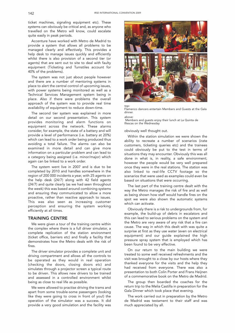
ticket machines, signaling equipment etc). Thesesystems can obviously be critical and, as anyone whotravelled on the Metro will know, could escalatequite easily in peak periods.
Accenture have worked with Metro de Madrid toprovide a system that allows all problems to bemanaged clearly and effectively. This provides ahelp desk to manage issues quickly and efficientlywhilst there is also provision of a second tier (oragents) that are sent out to site to deal with faultyequipment (Ticketing and Turnstiles account for40% of the problems).
The system was not just about people howeverand there are a number of mentoring systems inplace to alert the central control of upcoming issues,with power systems being monitored as well as aTechnical Services Management system being inplace. Also if there were problems the overallapproach of the system was to provide real timeavailability of equipment to reduce down-time.
The second tier system was explained in moredetail on our second presentation. This systemprovides monitoring and alarm functions onequipment across the network. These alarmsconsider, for example, the state of a battery and willprovide a level of performance (i.e. battery at 20%)which can lead to a work order being produced thusavoiding a total failure. The alarms can also beexamined in more detail and can give moreinformation on a particular problem and can lead toa category being assigned (i.e. minor/major) whichagain can be linked to a work order.
The system went live in 2007 and is due to becompleted by 2010 and handles somewhere in theregion of 200 000 incidents a year, with 25 agents onthe help desk (24/7) along with 42 field agents(24/7) and quite clearly (as we had seen throughoutthe week) this was based around combining systemsand ensuring they communicated to allow a moreproactive, rather than reactive approach to issues.This was also seen as increasing customerperception and ensuring the system workingefficiently at all times.
TRAINING CENTREWe were given a tour of the training centre within
the complex where there is a full driver simulator, acomplete replication of the station environment(ticket office, barriers etc) and finally a facility thatdemonstrates how the Metro deals with the risk offires.
The driver simulator provides a complete unit anddriving compartment and allows all the controls tobe operated as they would in real operation(checking the doors, closing doors etc) andsimulates through a projector screen a typical routeto be driven. This allows new drivers to be trainedand assessed in a controlled environment whilstbeing as close to real life as possible.
We were allowed to practise driving the trams andapart from some trouble-some passengers (lookinglike they were going to cross in front of you!) theoperation of the simulator was a success. It didprovide a very good simulation and the facility was
obviously well thought out.
Within the station simulation we were shown theability to recreate a number of scenarios (iratecustomers, ticketing queries etc) and the traineescould obviously be put to the test in terms ofsituations they may encounter. Obviously this was alldone in what is, in reality, a safe environment;however the people would be very well preparedonce they were in the real stations. The station wasalso linked to real-life CCTV footage so thescenarios that were used as examples could even bebased on situations that were occurring.
The last part of the training centre dealt with theway the Metro manages the risk of fire and as wellas being shown how staff would handle fires on thespot we were also shown the automatic systemswhich can activate.
Obviously there is a risk to undergrounds from, forexample, the build-up of debris in escalators andthis can lead to serious problems on the system andthe Metro are very aware of any risk that a fire cancause. The way in which this dealt with was quite asurprise at first as they use water (even on electricalequipment) and our guide explained the highpressure spray system that is employed which hasbeen found to be very effective.
On our return to the main building we weretreated to some well received refreshments and thevisit was brought to a close by our hosts where theythanked everyone for the visits and the help theyhad received from everyone. There was also apresentation to both Colin Porter and Frans Heijnenof a commemorative book on the Metro de Madrid.
The group then boarded the coaches for thereturn trip to the Melia Castilla in preparation for theGala Dinner which took place that evening.
The work carried out in preparation by the Metrode Madrid was testament to their staff and wasmuch appreciated by all.
142 IRSE INTERNATIONAL CONVENTION 2009
top: Flamenco dancers entertain Members and Guests at the Galadinner.
above:Members and guests enjoy their lunch at La Quinta de
Illescas on the Wednesday
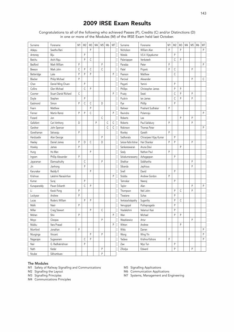
143
2009 IRSE Exam ResultsCongratulations to all of the following who achieved Passes (P), Credits (C) and/or Distinctions (D)
in one or more of the Modules (M) of the IRSE Exam held last October.
Surname Forename M1 M2 M3 M4 M5 M6 M7
Adepu Swetha Rani P
Antoney Biju P
Batchu Atchi Raju P C
Bedford Mark William P P
Beeson Mark John C P C C
Betteridge Luke P P P P
Blacker Philip Michael P
Chan Daniel Ming Chuen P
Collins Glen Michael C P
Coomer Stuart Daniel Richard C P
Doyle Stephen P
Eastmond Simon P C C D
Fearn Matthew P
Fenner Martin Ramzi P P C P
Fozard Jon C
Gallafant Carl Anthony D P C C
Gardner John Spencer C C
Gowthaman Selvaraju P
Hardcastle Alan George P
Heeley Daniel James P D C D
Howley James P
Hung Ho Man P
Ingram Phillip Alexander P
Jayaraman Elamvazhuthy C P
Jin Jianhong P
Karunakar Reddy K P
Krishnan Lakshmi Narasimhan P
Kumar Suraj P
Kunapareddy Pavan Srikanth C P
Li Kwok Pong P
Lockyear Andrew P
Lucas Roderic William P P
Malik Nasir P
Miller Craig Stewart P C
Mohan Shiv P P
Moyo Cleopas P
Mukku Vara Prasad P
Mumford Jonathan P
Munginga Vincent P P
Nagarajan Sugavanam C P
Nair G. Radhakrishnan P
Nath Kedar P
Ncube Sikhumbuzo P
Surname Forename M1 M2 M3 M4 M5 M6 M7
Nicholson William Alan P P P
Nistala V.S.V. Vijayakumar P
Palaniappan Venkatesh C P
Paradza Peter P P
Patel Priyank P C P
Pearson Matthew C
Percival Alexander P C
Peyyeti Yamini P
Phillips Christopher James P P
Prusty Swati C P P
Puckrin Ian James C P P
Pye Phillip P
Raikwar Prashant Sudhakar P
Ravindra Polamraju P
Roberts Lee P P
Roberts Paul Salisbury P P
Robinson Thomas Peter P
Rowley Gareth P
Sadhanala Chiranjeevi Vijay Kumar P
Sankaran Radha Krishnan Hari Shankar P P P
Sankareswaran Aruna Devi P
Sealy Nathan Paul P
Selvakumaraswamy Azhagappan P
Shekhar Siddhartha P
Sibanda Jephious P
Snell David P
Stubbs Andrew Gordon P
Tamrakar Neeraj P
Taylor Alan P P
Thompson Neil John P C P
Tiwatane Suhas P
Venkatachalapathy Suganthy P C
Venugopal Pothapragada P
Visalakshmi Velamuri Kasi P
Wan Michael P P
Waszkiewicz Artur P
Witton Andrew P
Witts Darren P
Wong Wing Yin P
Yadava Krishna Kishore P P
Zaw Myo Tun P
Zifodya Edward P P
The ModulesM1 Safety of Railway Signalling and CommunicationsM2 Signalling the LayoutM3 Signalling PrinciplesM4 Communications Principles
M5 Signalling ApplicationsM6 Communication ApplicationsM7 Systems, Management and Engineering
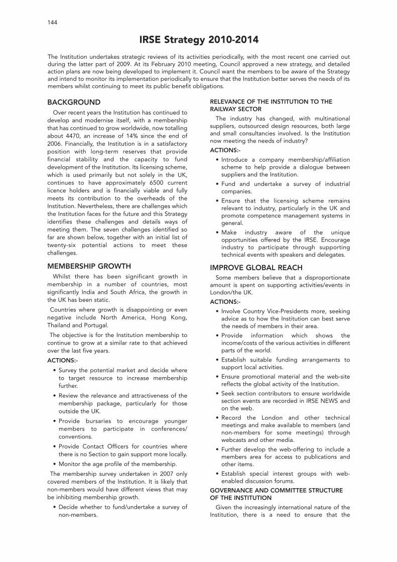
BACKGROUNDOver recent years the Institution has continued to
develop and modernise itself, with a membershipthat has continued to grow worldwide, now totallingabout 4470, an increase of 14% since the end of2006. Financially, the Institution is in a satisfactoryposition with long-term reserves that providefinancial stability and the capacity to funddevelopment of the Institution. Its licensing scheme,which is used primarily but not solely in the UK,continues to have approximately 6500 currentlicence holders and is financially viable and fullymeets its contribution to the overheads of theInstitution. Nevertheless, there are challenges whichthe Institution faces for the future and this Strategyidentifies these challenges and details ways ofmeeting them. The seven challenges identified sofar are shown below, together with an initial list oftwenty-six potential actions to meet thesechallenges.
MEMBERSHIP GROWTHWhilst there has been significant growth in
membership in a number of countries, mostsignificantly India and South Africa, the growth inthe UK has been static.
Countries where growth is disappointing or evennegative include North America, Hong Kong,Thailand and Portugal.
The objective is for the Institution membership tocontinue to grow at a similar rate to that achievedover the last five years.
ACTIONS:-
• Survey the potential market and decide whereto target resource to increase membershipfurther.
• Review the relevance and attractiveness of themembership package, particularly for thoseoutside the UK.
• Provide bursaries to encourage youngermembers to participate in conferences/conventions.
• Provide Contact Officers for countries wherethere is no Section to gain support more locally.
• Monitor the age profile of the membership.
The membership survey undertaken in 2007 onlycovered members of the Institution. It is likely thatnon-members would have different views that maybe inhibiting membership growth.
• Decide whether to fund/undertake a survey ofnon-members.
RELEVANCE OF THE INSTITUTION TO THERAILWAY SECTOR
The industry has changed, with multinationalsuppliers, outsourced design resources, both largeand small consultancies involved. Is the Institutionnow meeting the needs of industry?
ACTIONS:-
• Introduce a company membership/affiliationscheme to help provide a dialogue betweensuppliers and the Institution.
• Fund and undertake a survey of industrialcompanies.
• Ensure that the licensing scheme remainsrelevant to industry, particularly in the UK andpromote competence management systems ingeneral.
• Make industry aware of the uniqueopportunities offered by the IRSE. Encourageindustry to participate through supportingtechnical events with speakers and delegates.
IMPROVE GLOBAL REACHSome members believe that a disproportionate
amount is spent on supporting activities/events inLondon/the UK.
ACTIONS:-
• Involve Country Vice-Presidents more, seekingadvice as to how the Institution can best servethe needs of members in their area.
• Provide information which shows theincome/costs of the various activities in differentparts of the world.
• Establish suitable funding arrangements tosupport local activities.
• Ensure promotional material and the web-sitereflects the global activity of the Institution.
• Seek section contributors to ensure worldwidesection events are recorded in IRSE NEWS andon the web.
• Record the London and other technicalmeetings and make available to members (andnon-members for some meetings) throughwebcasts and other media.
• Further develop the web-offering to include amembers area for access to publications andother items.
• Establish special interest groups with web-enabled discussion forums.
GOVERNANCE AND COMMITTEE STRUCTUREOF THE INSTITUTION
Given the increasingly international nature of theInstitution, there is a need to ensure that the
144
The Institution undertakes strategic reviews of its activities periodically, with the most recent one carried outduring the latter part of 2009. At its February 2010 meeting, Council approved a new strategy, and detailedaction plans are now being developed to implement it. Council want the members to be aware of the Strategyand intend to monitor its implementation periodically to ensure that the Institution better serves the needs of itsmembers whilst continuing to meet its public benefit obligations.
IRSE Strategy 2010-2014
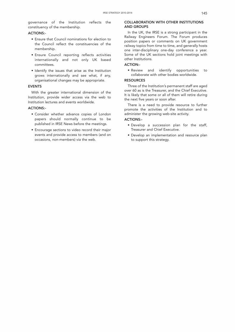
governance of the Institution reflects theconstituency of the membership.
ACTIONS:-
• Ensure that Council nominations for election tothe Council reflect the constituencies of themembership.
• Ensure Council reporting reflects activitiesinternationally and not only UK basedcommittees.
• Identify the issues that arise as the Institutiongrows internationally and see what, if any,organisational changes may be appropriate.
EVENTS
With the greater international dimension of theInstitution, provide wider access via the web toInstitution lectures and events worldwide.
ACTIONS:-
• Consider whether advance copies of Londonpapers should normally continue to bepublished in IRSE News before the meetings.
• Encourage sections to video record their majorevents and provide access to members (and onoccasions, non-members) via the web.
COLLABORATION WITH OTHER INSTITUTIONSAND GROUPS
In the UK, the IRSE is a strong participant in theRailway Engineers Forum. The Forum producesposition papers or comments on UK governmentrailway topics from time to time, and generally hostsone inter-disciplinary one-day conference a year.Some of the UK sections hold joint meetings withother Institutions.
ACTION:-
• Review and identify opportunities tocollaborate with other bodies worldwide.
RESOURCES
Three of the Institution’s permanent staff are agedover 60 as is the Treasurer, and the Chief Executive.It is likely that some or all of them will retire duringthe next five years or soon after.
There is a need to provide resource to furtherpromote the activities of the Institution and toadminister the growing web-site activity.
ACTIONS:-
• Develop a succession plan for the staff,Treasurer and Chief Executive.
• Develop an implementation and resource planto support this strategy.
145IRSE STRATEGY 2010-2014
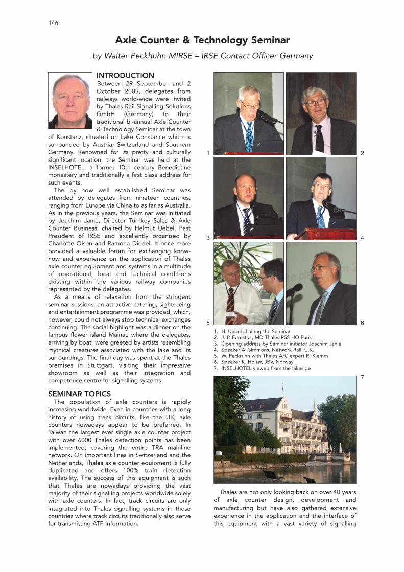
INTRODUCTIONBetween 29 September and 2October 2009, delegates fromrailways world-wide were invitedby Thales Rail Signalling SolutionsGmbH (Germany) to theirtraditional bi-annual Axle Counter& Technology Seminar at the town
of Konstanz, situated on Lake Constance which issurrounded by Austria, Switzerland and SouthernGermany. Renowned for its pretty and culturallysignificant location, the Seminar was held at theINSELHOTEL, a former 13th century Benedictinemonastery and traditionally a first class address forsuch events.
The by now well established Seminar wasattended by delegates from nineteen countries,ranging from Europe via China to as far as Australia.As in the previous years, the Seminar was initiatedby Joachim Janle, Director Turnkey Sales & AxleCounter Business, chaired by Helmut Uebel, PastPresident of IRSE and excellently organised byCharlotte Olsen and Ramona Diebel. It once moreprovided a valuable forum for exchanging know-how and experience on the application of Thalesaxle counter equipment and systems in a multitudeof operational, local and technical conditionsexisting within the various railway companiesrepresented by the delegates.
As a means of relaxation from the stringentseminar sessions, an attractive catering, sightseeingand entertainment programme was provided, which,however, could not always stop technical exchangescontinuing. The social highlight was a dinner on thefamous flower island Mainau where the delegates,arriving by boat, were greeted by artists resemblingmythical creatures associated with the lake and itssurroundings. The final day was spent at the Thalespremises in Stuttgart, visiting their impressiveshowroom as well as their integration andcompetence centre for signalling systems.
SEMINAR TOPICSThe population of axle counters is rapidly
increasing worldwide. Even in countries with a longhistory of using track circuits, like the UK, axlecounters nowadays appear to be preferred. InTaiwan the largest ever single axle counter projectwith over 6000 Thales detection points has beenimplemented, covering the entire TRA mainlinenetwork. On important lines in Switzerland and theNetherlands, Thales axle counter equipment is fullyduplicated and offers 100% train detectionavailability. The success of this equipment is suchthat Thales are nowadays providing the vastmajority of their signalling projects worldwide solelywith axle counters. In fact, track circuits are onlyintegrated into Thales signalling systems in thosecountries where track circuits traditionally also servefor transmitting ATP information.
Thales are not only looking back on over 40 yearsof axle counter design, development andmanufacturing but have also gathered extensiveexperience in the application and the interface ofthis equipment with a vast variety of signalling
146
Axle Counter & Technology Seminarby Walter Peckhuhn MIRSE – IRSE Contact Officer Germany
1. H. Uebel chairing the Seminar2. J.-P. Forestier, MD Thales RSS HQ Paris3. Opening address by Seminar initiator Joachim Janle4. Speaker A. Simmons, Network Rail, U.K.5. W. Peckruhn with Thales A/C expert R. Klemm6. Speaker K. Holter, JBV, Norway7. INSELHOTEL viewed from the lakeside
1
3
5
2
4
6
7
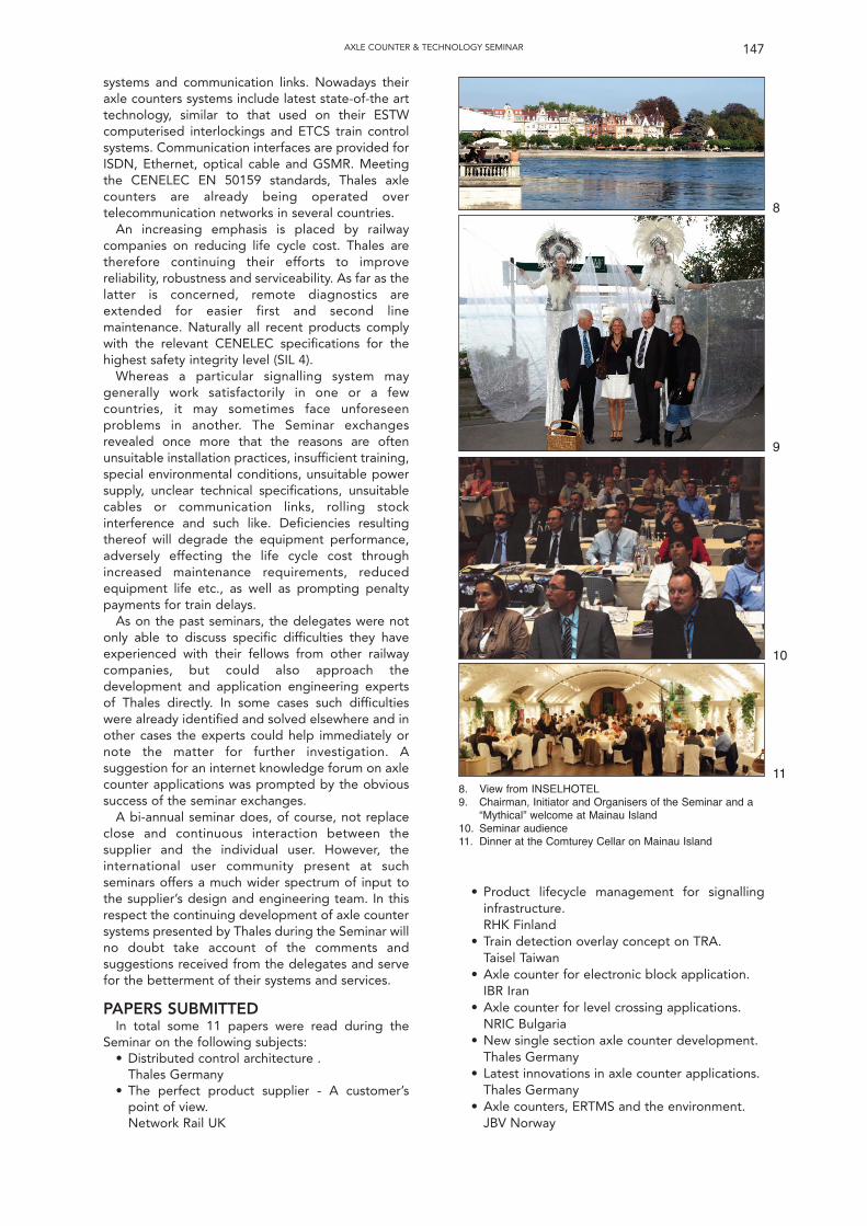
systems and communication links. Nowadays theiraxle counters systems include latest state-of-the arttechnology, similar to that used on their ESTWcomputerised interlockings and ETCS train controlsystems. Communication interfaces are provided forISDN, Ethernet, optical cable and GSMR. Meetingthe CENELEC EN 50159 standards, Thales axlecounters are already being operated overtelecommunication networks in several countries.
An increasing emphasis is placed by railwaycompanies on reducing life cycle cost. Thales aretherefore continuing their efforts to improvereliability, robustness and serviceability. As far as thelatter is concerned, remote diagnostics areextended for easier first and second linemaintenance. Naturally all recent products complywith the relevant CENELEC specifications for thehighest safety integrity level (SIL 4).
Whereas a particular signalling system maygenerally work satisfactorily in one or a fewcountries, it may sometimes face unforeseenproblems in another. The Seminar exchangesrevealed once more that the reasons are oftenunsuitable installation practices, insufficient training,special environmental conditions, unsuitable powersupply, unclear technical specifications, unsuitablecables or communication links, rolling stockinterference and such like. Deficiencies resultingthereof will degrade the equipment performance,adversely effecting the life cycle cost throughincreased maintenance requirements, reducedequipment life etc., as well as prompting penaltypayments for train delays.
As on the past seminars, the delegates were notonly able to discuss specific difficulties they haveexperienced with their fellows from other railwaycompanies, but could also approach thedevelopment and application engineering expertsof Thales directly. In some cases such difficultieswere already identified and solved elsewhere and inother cases the experts could help immediately ornote the matter for further investigation. Asuggestion for an internet knowledge forum on axlecounter applications was prompted by the obvioussuccess of the seminar exchanges.
A bi-annual seminar does, of course, not replaceclose and continuous interaction between thesupplier and the individual user. However, theinternational user community present at suchseminars offers a much wider spectrum of input tothe supplier’s design and engineering team. In thisrespect the continuing development of axle countersystems presented by Thales during the Seminar willno doubt take account of the comments andsuggestions received from the delegates and servefor the betterment of their systems and services.
PAPERS SUBMITTEDIn total some 11 papers were read during the
Seminar on the following subjects:• Distributed control architecture .
Thales Germany• The perfect product supplier - A customer’s
point of view.Network Rail UK
• Product lifecycle management for signallinginfrastructure.RHK Finland
• Train detection overlay concept on TRA.Taisel Taiwan
• Axle counter for electronic block application.IBR Iran
• Axle counter for level crossing applications.NRIC Bulgaria
• New single section axle counter development.Thales Germany
• Latest innovations in axle counter applications.Thales Germany
• Axle counters, ERTMS and the environment.JBV Norway
147AXLE COUNTER & TECHNOLOGY SEMINAR
8. View from INSELHOTEL9. Chairman, Initiator and Organisers of the Seminar and a
“Mythical” welcome at Mainau Island10. Seminar audience11. Dinner at the Comturey Cellar on Mainau Island
8
9
10
11
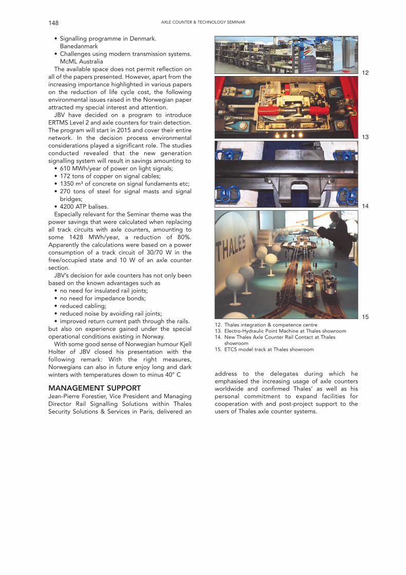
• Signalling programme in Denmark.Banedanmark
• Challenges using modern transmission systems.McML Australia
The available space does not permit reflection onall of the papers presented. However, apart from theincreasing importance highlighted in various paperson the reduction of life cycle cost, the followingenvironmental issues raised in the Norwegian paperattracted my special interest and attention.
JBV have decided on a program to introduceERTMS Level 2 and axle counters for train detection.The program will start in 2015 and cover their entirenetwork. In the decision process environmentalconsiderations played a significant role. The studiesconducted revealed that the new generationsignalling system will result in savings amounting to
• 610 MWh/year of power on light signals;• 172 tons of copper on signal cables;• 1350 m³ of concrete on signal fundaments etc;• 270 tons of steel for signal masts and signal
bridges;• 4200 ATP balises.Especially relevant for the Seminar theme was the
power savings that were calculated when replacingall track circuits with axle counters, amounting tosome 1428 MWh/year, a reduction of 80%.Apparently the calculations were based on a powerconsumption of a track circuit of 30/70 W in thefree/occupied state and 10 W of an axle countersection.
JBV’s decision for axle counters has not only beenbased on the known advantages such as
• no need for insulated rail joints;• no need for impedance bonds;• reduced cabling;• reduced noise by avoiding rail joints;• improved return current path through the rails.
but also on experience gained under the specialoperational conditions existing in Norway.
With some good sense of Norwegian humour KjellHolter of JBV closed his presentation with thefollowing remark: With the right measures,Norwegians can also in future enjoy long and darkwinters with temperatures down to minus 40° C
MANAGEMENT SUPPORTJean-Pierre Forestier, Vice President and ManagingDirector Rail Signalling Solutions within ThalesSecurity Solutions & Services in Paris, delivered an
148 AXLE COUNTER & TECHNOLOGY SEMINAR
12. Thales integration & competence centre13. Electro-Hydraulic Point Machine at Thales showroom14. New Thales Axle Counter Rail Contact at Thales
showroom15. ETCS model track at Thales showroom
address to the delegates during which heemphasised the increasing usage of axle countersworldwide and confirmed Thales’ as well as hispersonal commitment to expand facilities forcooperation with and post-project support to theusers of Thales axle counter systems.
12
13
14
15
149
Younger Members’ 2009Seminar & Technical Visit
SIGNALLING TECHNOLOGY, OLD ANDNEWDAY 1
A sunny morning on Thursday 12 November 2009saw a cohort of IRSE members and otherprofessionals descend on the National RailwayMuseum in York for the annual IRSE YoungerMembers seminar. Following on from the success ofthe 2008 seminar in Glasgow, the stakes were high,but with a perfect venue, the solid theme of theseminar – Signalling Technology, Old and New – anda line up of eminent speakers, the event was surely‘on track’ for success.
The day kicked off with an opening address fromour Chief Executive, Colin Porter. Colincongratulated the organisers on the excellentturnout – over 100 people were in attendance andfilled the conference room. The Younger Memberswere also praised for continuing to be just as activeand dynamic as Colin recalled the Student andGraduate section to be in his early days with theinstitution. Colin closed by motivating the YoungerMembers to continue to take an ever increasing rolein the institution and to challenge and give feedbackto help ensure that the institution remains aligned totheir ambitions and needs.
Peter Woodbridge of Invensys Rail, a well knownface to the Younger Members, set the scene bygiving the first presentation of the day on the earlyprinciples of signalling. This actually covered ahistory of signalling principles right through fromthe early days of the policeman ‘bobby’ rightthrough to ERTMS in the present day, with some ofthe key events and developments along the waysuch as semaphore and power signalling. Peter livedup to expectations and managed to cram a wealthof information into the short time available. Peterconcluded by reminding everyone that it is alwaysimportant that we understand why things are theway they are and to remember and learn from thelessons of the past when looking to the future.
Rodrigo Alvarez Garcia Sanchidrian of NetworkRail followed hot on the heels of Peter by giving atechnical overview of the GSM-R system and itsapplication to Network Rail in the UK along with thenew Fixed Telecommunications Network. Theaudience was provided with a comprehensiveunderstanding of the main building blocks thatmake up the GSM-R system and the features thatbuild on the public GSM system we all use everydaywith our mobile phones.
After a short coffee break, two speakers werelined up to provide some real project experiencesof ERTMS implementation. Dave Fenner ofNetwork Rail took the lead by outlining thefundamentals of ERTMS and the various modes ofsystem operation, before moving on to the real lifeapplication of the technology to the Cambrian linein the UK. Dave described some of the challengesand opportunities that are surfacing for thesignalling engineer.
Ronald Bresser of Movares then contrasted thiswith ERTMS projects in the Netherlands. Ronaldpaid particular attention to the Betuweroute freightline between Rotterdam and Germany, and gave auseful insight into many of the problems that havebeen faced along the way.
Following a spot of lunch, Tony Kornas of InvensysRail tackled the fundamentals of point operatingmechanisms and the role of the signal engineer inthis multi-disciplinary interface. Tony remarked thatthis was to be an updated version of a presentationhe gave to the IRSE a few years ago, although whendusting it down it became quite apparent how littlehad changed! The presentation detailed the mainpoint machine types and some of the features andissues associated with each type. This concluded bylooking forward to some of the developments forpoint machines of the future. The key to achieving agood point machine for the future would seem to beto take the best bits from the point machines oftoday where possible, enhance them whererequired, and then wrap them all together in asimple and integrated system that supports minimaland easy maintenance.
After a short technical hitch and an – unplanned –demonstration of the principles of redundancy,Brian Mulvana of Network Rail took to the floor togive a run down on the work of the level crossingteam based in York. It is without question that levelcrossings represent the single biggest risk in termsof railway safety in the UK, and Network Rail isextremely focussed in reducing this risk throughcampaigns and/or technical solutions. Brianpresented an entertaining yet informative overviewof the main level crossing types from user workedcrossings to full barrier crossings. A number of themain challenges and causes of risk were presented,along with some of the different solutions andtechnologies that are being considered and
Martin Fenner, YM committee,introducing theevent
implemented to drive the risk down, such asmagnetic locks on gates and radar to detectobstacles at the crossing for example. It wassurprising just how cheap some of the solutionsactually are when weighed up against the very realbenefits that they might bring.
The next speaker, Xen Christodoulou of LondonUnderground, gave the audience a differentviewpoint on introducing new technology byintroducing the important principle of cross-acceptance whereby a system is accepted into usebased on an existing certification elsewhere and athorough assessment of the differences to its nativeenvironment. Xen apologised to the audience forthe lack of exciting pictures/photos given the natureof the presentation, but this was not required as heproceeded to give a lively and interestingpresentation on what is a very important but oftenmisunderstood process. It was acknowledged by thespeaker that while the principle is relativelystraightforward, cross-acceptance in practice can bevery challenging and can even effectively lead to afull assessment of the system from first principles inthe worst of cases. However, if managed andapplied correctly, cross-acceptance can significantlyreduce the time and cost of the acceptance process.
Richard Lant of Network Rail brought thepresentations to a close with an overview of axlecounter technology and its application in the UK,with particular attention to the AzLM system. Sincethe West Coast Mainline project, the rollout of axlecounters in the UK has been gaining ground, but asRichard indicated, this has not been without itsproblems along the way. An outline of some of theproblems was given along with some interestingfacts regarding axle counter reliability on the variousprojects to which they’ve been applied. It isencouraging to see that many of the earlierproblems have now been resolved and that axlecounter reliability is starting to meet the targets seton many of the schemes to which they’ve beenapplied.
The final part of the day saw the speakers engagein a lively debate with the audience, where manytopical issues were discussed. With no end to theenthusiasm of the audience in sight, the organisersreluctantly had to stand firm and draw the seminarto a close. The day had certainly lived up toexpectations and with the breadth and depth ofmaterial covered it seemed that it had provedinteresting and informative for all delegates.
DAY 2
The second day of the seminar promised to be asinteresting as the first, with a variety of events linedup. The morning session was based at Saxby Housewith Invensys Rail where the delegation divided intogroups to be shown around the differentdepartments, where presentations anddemonstrations were given on some of theequipment that Invensys has developed over theyears. These are briefly described below.
Solid State Interlocking (SSI)
SSI was developed by GEC (now ALSTOM/Signalling Solutions), Westinghouse (now Invensys)
and British Rail in the 1980’s, with the aspiration toreduce and near eliminate the need for signallingrelays on a scheme. It is a military style vitalcomputer system with two out of three redundancy(i.e. there are three processors, of which at least twoout of three must agree based on receivedinformation, before any action can be taken). Aswith any interlocking, SSI is considered to be safety-critical and is therefore designed to be fail safe,utilising high integrity software appropriate to theSafety Integrity Level (SIL) 4 application.
The SSI processing speed is 2MHz and theinterlocking data relating to the area of railwayunder control is stored on Erasable ProgrammableRead-Only Memory (EPROM) devices. As signallingarrangements have become more complex over thelast ten years, the quantity of data hasproportionally increased which starts to highlightthe limits of what SSI is capable of. Features such asAutomatic Route Setting (ARS) interface capabilityand Train Operated Route Release (TORR) can beprogrammed in to ease a Signaller’s job wherenecessary.
Another notable fact of SSI is that a lot of theprinciples testing can be done off-site, thusreducing risk and minimising disruption at the pointof installation and commissioning.
WESTLOCK
The WESTLOCK system is one of the two modernderivatives of SSI (the other is ALSTOM’sSMARTLOCK) and has the equivalent capacity offour conventional SSI interlockings. This reduces thenumber of separate interlockings required for agiven job, which in turn reduces the number ofinterlocking boundaries and the significant workthat is associated with managing these boundariesboth physically and in terms of data preparation.However, one possible disadvantage of such a largeinterlocking is that a bigger area of control isaffected in the event of system failure or duringsystem modification/upgrade.
WESTLOCK also provides an improved diagnosticcomputer for the maintenance Technician. One canuse this to monitor as many different pieces ofequipment within the interlocking area as required(both track side as well as in locations or RelocatableEquipment Buildings). It also automatically logs anyfailures. The delegates were shown one of theseterminals and the ease with which one can drag anddrop the equipment for monitoring onto the mainscreen to begin receiving diagnostic information.
WESTLOCK works using the same principles as itspredecessor, thus making. the system backwardscompatible and able to communicate and controlexisting SSI equipment.
WESTeX
The current type approved heart of the WESTeXsuite of level crossing products is the GCP3000. Thisis much smaller, simpler and cheaper than existingsystems because there is far less equipmentrequired. This is partly due to the use of the LevelCrossing Predictor (LCP), which is very much like ana.c. track circuit. As a train approaches, sensors
150 YOUNG MEMBERS’ 2009 SEMINAR AND TECHNICAL VISIT
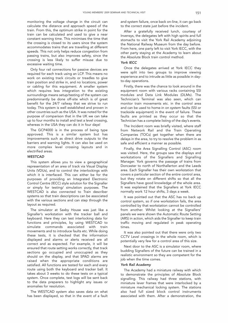
monitoring the voltage change in the circuit cancalculate the distance and approach speed of thetrain. From this, the optimum strike in point for thetrain can be calculated and used to give a nearconstant warning time. This minimises the time thatthe crossing is closed to its users since the systemaccommodates trains that are travelling at differentspeeds. This not only helps reduce congestion frompassing trains, but also improves safety, since thecrossing is less likely to suffer misuse due toexcessive waiting time.
Only four rail connections for passive devices arerequired for each track using an LCP. This means nowork on existing track circuits or treadles to givetrain position and strike in, and no locations, poweror cabling for this equipment. A smaller systemwhich requires less integration to the existingsurroundings means setup/testing of the system canpredominantly be done off-site which is of greatbenefit for the 24/7 railway that we strive to runtoday. This system is well established and proven inother countries such as the USA. It was noted for thepurpose of comparison that in the UK we can takeup to four months to install and test a level crossing,whereas in the USA they can do it in four days!
The GCP4000 is in the process of being typeapproved. This is a similar system but hasimprovements such as direct drive outputs to thebarriers and warning lights. It can also be used onmore complex level crossing layouts and inelectrified areas.
WESTCAD
This system allows you to view a geographicalrepresentation of an area of track via Visual DisplayUnits (VDUs), and to control the interlockings withwhich it is interfaced. This can either be for thepurposes of providing an Integrated ElectronicControl Centre (IECC) style solution for the Signalleror simply for testing/ simulation purposes. TheWESTCAD is also connected to Train describersystems so that train descriptions can be associatedwith the various sections and can step through thelayout as required.
The simulator at Saxby House was just like aSignaller’s workstation with the tracker ball andkeyboard. Here they can test interlocking data forfunctions and principles, by using WESTCAD tosimulate commands associated with trainmovements and to introduce faults etc. While doingthese tests, it is checked that the informationdisplayed and alarms or alerts received are allcorrect and as expected. For example, it will beensured that route setting works correctly, that tracksections go occupied and unoccupied as theyshould on the display, and that SPAD alarms areraised when the appropriate conditions aresatisfied. All functions are tested for each and everyroute using both the keyboard and tracker ball. Ittakes about 3 weeks to do these tests on a typicalsystem. Once complete, test logs will be sent backto the data preparers to highlight any issues oranomalies for resolution.
The WESTCAD system also saves data on whathas been displayed, so that in the event of a fault
and system failure, once back on-line, it can go backto the correct state just before the incident.
After a gratefully received lunch, courtesy ofInvensys, the delegates left with high spirits and fullstomachs to visit the York Rail Academy adjoiningthe National Railway Museum from the day before.From here, one party left to visit York IECC, with theother party staying at the Academy to learn aboutthe Absolute Block train control method.
York IECC
Once the delegates arrived at York IECC theywere split into two groups to improve viewingexperience and to intrude as little as possible in day-to-day operations.
Firstly, there was the chance to look around in theequipment room with various racks containing SSImodules and Data Link Modules (DLMs). TheTechnician’s Terminal was also seen, which canmonitor train movements etc. in the control areaand can be used to home-in on system faults (SSI ortrackside equipment) in the event of failure. Thesefaults are printed as they occur so that theTechnician has a complete listing of the day’s events.
The Incident room was briefly visited, where stafffrom Network Rail and the Train OperatingCompanies (TOCs) get together when there aredelays in the area, to try to resolve the problem in assafe and efficient a manner as possible.
Finally, the Area Signalling Control (ASC) roomwas visited. Here, the groups saw the displays andworkstations of the Signallers and SignallingManager. York governs the passage of trains fromDoncaster to north of Northallerton and the Leedsarea. Each Signaller has their own workstation thatcovers a particular section of the entire control area,but they rotate on different shifts so that all theSignallers have good knowledge of the whole area.It was explained that the Signallers at York IECCnormally work 12 hour shifts, 3 days a week.
It was pointed out that the ASC has no back upcontrol system, so if one workstation fails, the areacontrolled by that workstation cannot be controlledfrom another. Whilst looking at the Signallers’panels we were shown the Automatic Route Setting(ARS) in action, which aids the Signaller to keep traintraffic moving and regulated in peak operatingtimes.
It was also pointed out that there were only twoCCTV Level crossings in the whole room, which ispotentially very few for a control area of this size.
Next door to the ASC is a simulator room, wherebudding Signallers of the future can be trained in arealistic environment so they are competent for thejob when the time comes.
York Rail Academy
The Academy had a miniature railway with whichto demonstrate the principles of Absolute Blocksignalling. This railway had three stations, withminiature lever frames that were interlocked by aminiature mechanical locking system. The stationsalso had full sized block control instrumentsassociated with them. After a demonstration, the
151YOUNG MEMBERS’ 2009 SEMINAR AND TECHNICAL VISIT
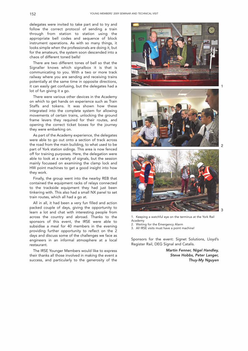
delegates were invited to take part and to try andfollow the correct protocol of sending a trainthrough from station to station using theappropriate bell codes and sequence of blockinstrument operations. As with so many things, itlooks simple when the professionals are doing it, butfor the amateurs, the system soon descended into achaos of different toned bells!
There are two different tones of bell so that theSignaller knows which signalbox it is that iscommunicating to you. With a two or more trackrailway where you are sending and receiving trainspotentially at the same time in opposite directions,it can easily get confusing, but the delegates had alot of fun giving it a go.
There were various other devices in the Academyon which to get hands on experience such as TrainStaffs and tokens. It was shown how theseintegrated into the complete system for allowingmovements of certain trains, unlocking the groundframe levers they required for their routes, andopening the correct ticket boxes for the journeythey were embarking on.
As part of the Academy experience, the delegateswere able to go out onto a section of track acrossthe road from the main building, to what used to bepart of York station sidings. This area is now fencedoff for training purposes. Here, the delegation wereable to look at a variety of signals, but the sessionmainly focussed on examining the clamp lock andHW point machines to get a good insight into howthey work.
Finally, the group went into the nearby REB thatcontained the equipment racks of relays connectedto the trackside equipment they had just beentinkering with. This also had a small NX panel to settrain routes, which all had a go at.
All in all, it had been a very fun filled and actionpacked couple of days, giving the opportunity tolearn a lot and chat with interesting people fromacross the country and abroad. Thanks to thesponsors of this event, the IRSE were able tosubsidise a meal for 40 members in the eveningproviding further opportunity to reflect on the 2days and discuss some of the challenges we face asengineers in an informal atmosphere at a localrestaurant.
The IRSE Younger Members would like to expresstheir thanks all those involved in making the event asuccess, and particularly to the generosity of the
Sponsors for the event: Signet Solutions, Lloyd’sRegister Rail, DEG Signal and Catalis.
Martin Fenner, Nigel Handley,Steve Hobbs, Peter Langer,
Thuy-My Nguyen
152 YOUNG MEMBERS’ 2009 SEMINAR AND TECHNICAL VISIT
1. Keeping a watchful eye on the terminus at the York RailAcademy2. Waiting for the Emergency Alarm3. All IRSE visits must have a point machine!
1
2
3
153
The Future Education and Training of Train Control Engineersand Technicians
by Ken Burrage
INTRODUCTIONThe Institution’s Professional Development
Committee had arranged this seminar to considerthe important questions that the changes to railwayorganisations/structures over the last twenty yearshave posed to the training and development ofengineers and technicians for the future.
The Institution’s President, Frans Heijnen andChief Executive, Colin Porter, led the seminar andspeakers were chosen from a cross-section ofrailway administrations and supply organisationsfrom around the world.
THE SCALE OF THE PROBLEMAfter an introduction by the President the
seminar opened with sessions that described theimpact of recent change on the personaldevelopment of S&T engineers and technicians,considered what future business requirementswould be and information about currentpopulation demographics. Eddie Goddard, Headof Engineering, LUL Line Upgrades and SteveHailes, Director, Control and CommunicationsEngineering, Network Rail gave the keynoteaddresses. Eddie explained, by using the exampleof his own career, the traditional route forproducing S&T engineers, which involvedstructured ‘on the job’ training in a wide range ofS&T activities including time spent with theoperations function and employer support toachieve academic qualifications. Thesearrangements were typical in the verticallyintegrated railway administrations that existed upuntil the 1990s. The privatisation arrangements,implemented first in the UK but then alsoelsewhere around the world, led to organisationalfragmentation to a greater or lesser degree andthe demise of traditional S&T training schemes. Inthe post privatised fragmented railway it is muchmore difficult to arrange training and developmentexperiences that will produce the well rounded,competent, motivated engineers and techniciansthat the railway needs for the future. Stevereviewed the recent training and developmenthistory from a Network Rail perspective, describingthe 10 year gap when recruitment of bothgraduates and technicians had been curtailed inthe immediate pre and post-privatisation periodfrom 1994 and explained that more IncorporatedEngineers were required to become the front-linemanagers of the S&T work force of the future.Given the life of signalling systems, it would still benecessary to train people in mechanicalinstallations for many years to come in his view, aswell as dealing with the full range of more moderntechnology. He was concerned that a “complianceculture” had developed without people necessarilyunderstanding the underlying principles and
reasoning, and felt that signal engineers of thefuture needed to be equipped to challengeinappropriate standards. He suggested we neededto establish an industry-wide vision on futuretraining requirements, and finished by drawingattention to the Association of Train OperatingCompanies’ cross-industry training scheme whichhad been running for several years.
We then heard from Paul Jackson, ChiefExecutive, Engineering Technology Board, whoexplained the societal changes impacting upon thefuture recruitment of railway S&T engineers andtechnicians. In the UK there is an ageingpopulation, there will be a 16 per cent decline inthe number of 18 year olds in the next ten yearsresulting in fewer potential starters. Also, acrossthe UK, fewer than 60 per cent of students onfurther education engineering courses actuallycomplete them, so there are fewer completers, andwe are already facing sector skills shortages in theUK including in railway construction andmaintenance. Young people have a poorperception of engineering as a career; only 18% of7-16 year olds perceive engineering as a desirablecareer and only 12% of 11-16 year olds currentlyclaim to have some knowledge of what engineersdo. He finished by describing some of theinitiatives being taken by the ETB (which heannounced would be re-launched as EngineeringUK on 1 December) to promote engineering toschool children, their teachers and parents. Onesuch event was the second Big Bang EngineeringFair to be held in Manchester in March 2010 and asecond was the “Tomorrow’s Engineers” initiativebeing run in conjunction with a wide range ofprofessional engineering bodies.
SOME CURRENT ISSUES/CONCERNSThe next session dealt with changes that are
occurring currently in the education of youngpeople and in general engineering qualifications.Kevin Marchand, from Go Skills, the UK Sector SkillsCouncil for passenger transport, who in conjunctionwith the IRSE produce the national occupationstandards for railway S&T engineering in the UK,explained that the approach to vocationalqualifications is changing. In future learners will gaincredits for demonstrating learning, credits will beadded together to earn a qualification and thenumber of credits will determine the qualificationtitles. It is envisaged that there will be three levels ofqualification, with 1 to 12 credits earning an‘Award’, 13 to 36 credits a ‘Certificate’ and morethan 37 credits a ‘Diploma’. The focus for 14 – 19year olds will be on preparation for employmenteither directly or through further learning. He alsoreferred to the work currently going on to set up theNational Skills Academy for Railway Engineering (in
which the IRSE is already participating). Work hasalready been done to identify shortages oftechnicians and engineers and the National SkillsAcademy concept is to add value through co-ordination/integration by undertaking detailedanalysis of gaps; information, advice and guidanceto attract recruits; training programmeaccreditation; trainer accreditation and a brokerageservice for employers and training organisations.
Bruce MacDougall, an IRSE Fellow andexperienced signal engineer, then gave apresentation drawing upon his own and other’sexperience and asking, “Have we got the balanceright and what can we do to help everyone achievetheir best?” His concern was prompted byknowledge of incidents where process had beenslavishly followed, engineering judgement was notexercised and the wrong conclusions were reached.In his experience the current training regimesexposed concerns about the initial introduction tothe S&T discipline being very variable; theimportance on ‘why’ something should be donerather than just ‘what’ should be done was also veryvariable; there was a lack of sufficient structure forconsistency of content or delivery. There was anexpectation gap and possible conflict for employersbetween employee career development versusproductivity; and a tendency for a ‘conveyor belt’approach at the training/job threshold. The end ofthe training course is not the completion of training;training and professional development has only justbegun and is a lifelong process.
PRESENT TRAINING INITIATIVESIn the first session after lunch, Bill Alexander,
National Training Manager for Network Rail, gavethe Seminar attendees details of Network Rail’s‘Advanced Apprenticeship Scheme’.
He explained that subsequent to the 2004decision to take infrastructure (including S&T)maintenance back ‘in-house’ after 10 years, (havingbeen the responsibility of a number of differentprivate company maintenance contractors as aresult of the privatisation of British Rail and duringthis time recruitment, training and developmentwas, at best fragmented and variable in quality) itwas decided to set up a standardised nationaltraining programme. A 25-year manpower-planninghorizon was assumed, with account being taken ofthe age profile, skills profile and anticipatedefficiency savings that could be achieved with theintroduction of new technology and methods ofwork.
It was decided to set up a 3-year AdvancedApprenticeship Scheme, based upon the Royal Navyengineering training establishment at HMS Sultan inPortsmouth, with the first year completed atPortsmouth, and then second and third year at thetrainees’ home depots, although with periods oftraining back at HMS Sultan. The scheme leads toNVQ level 3 qualifications in rail engineering and,after a competence assessment by an IRSEapproved competence assessor, an appropriatelevel IRSE licence, with a BEng foundation degree
being attainable by the best candidates. To date1089 apprentices covering track, signalling andelectrification and plant have entered the scheme,the retention rate is 94% and 396 have alreadycompleted the programme. There are plans toexpand the scheme to include locking fitters and tocover signal design and to take a further 1200apprentices over the next 5 years. The programmenot only provided technical training, but alsoprovided the young trainees with opportunities todemonstrate pride, teamwork, determination andrespect for others throughout the period of training,and after.
Andy Knight, Managing Director of SignetSolutions then gave a presentation on behalf ofCraig King, Technical Director of Catalis who wasnot able to be present, reporting upon the both thehistory of S&T training in British Rail and the presentS&T engineering training opportunities provided forindustry by Catalis. Catalis still owned the formerBR’s national S&T engineering training school atDerby, as well as other training facilities. Catalis sawthe future as providing opportunities for support oftraineeships, conversion schemes and graduatedevelopment programmes. Assistance in highereducation programmes, refresher and updateevents, standardised regional training centres, newinterlocking technologies, modular signalling,ERTMS/GSM-R and transmission based traincontrol. Craig also foresaw significant opportunitiesfor technology based training which has potentiallyvery cheap unit costs for large volume requirements,and is already successfully widely used for Signallertraining, and also internet delivery, distance learningand directed study.
Andy then went on to describe the work thatSignet Solutions had undertaken to run conversionprogrammes for experienced engineers from otherdisciplines in the 27 - 40 age profile to transfer theirskills to become S&T engineers.
Karl Dodsworth, Director (Engineering SystemsDivision) and Andrea Knight, (HR Director), fromBombardier Transportation then provided asupplier’s view on the seminar topic. Karl firstexplained the global background of Bombardier’sproducts and services, which are sold to numerousrailway administrations in more than 60 countriesworldwide. Bombardier has more than 30 000employees and a manufacturing presence in 22countries. Andrea explained that the age profile inthe world’s developed countries mirrored the ageprofile that is occurring in the UK and similarly, apartfrom India and the US, the world’s talent pool ofyounger people (under age 30) is also shrinking.
The shortage of skilled S&T engineers andtechnicians is therefore not just a UK phenomenon itis most definitely worldwide.
THE GLOBAL PERSPECTIVEBuddhadev Dutta-Chowdhury, from Bombardier
and Les Brearley from Ansaldo STS were the finalpresenters to the seminar. Buddhadev began bybriefly describing the huge undertaking that isIndian railways; 63 000 route km, 1.4 million
154 THE FUTURE EDUCATION AND TRAINING OF TRAIN CONTROL ENGINEERS AND TECHNICIANS
employees, 16 zonal railways with 3 to 6 DivisionalHeadquarters for each zone and a variation ofsignalling design in each zone. S&T training anddevelopment for Indian railways is undertaken bythe railway’s own centralised training establishment,the Indian Railways Institute of Signal Engineeringand Telecommunications (IRISET) at Secunderabad.This takes over 2000 officers and supervisors a year,has laboratories for hands-on practical training andprovides initial classroom and field training,refresher/equipment specific training, yoga,meditation and stress management courses. Thereare also 10 Regional Training Centres for techniciansacross India.
Buddhadev saw considerable benefit in thesupport the IRSE could give in providing a commonplatform via the IRSE exam to support competencydevelopment for the contractors down the supplychain, IRSE licensing expansion for the developingcountries and producing an internationallyacceptable syllabus for training with perhaps theIRSE’s International Technical Committee taking alead role to standardise and issue guidance on goodpractice.
For the final presentation of the day Les Brearleythen gave a view from an Australasian perspective.His presentation showed that Australia faced thefamiliar skills shortages and age profile problems forS&T engineers and technicians as had been notedearlier from the UK presentations. Problems alsoarose from the disaggregated nature of the railwayindustry in Australia coupled with numerousdifferent signalling standards, resulting in a generallack of critical mass in organisations to do training.Consequently the focus of the rail organisations ismainly ‘inhouse’ trade training.
There is limited training provision at engineeringlevel, which is also mainly ‘in-house’ and on the jobfrom the large companies that have trainingavailable e.g. Invensys do some basic generic,mainly product, training and Ansaldo have a suite ofgeneric and a range of product training. There isalso the IRSE Examination, which is held each year inAustralia. An industry wide approach was requiredand the big success story in Australia is theGraduate Diploma in S&T engineering run byCentral Queensland University, which had been setup in 2004 facilitated by the IRSE Australasiansection. This is a distance learning educationprogramme, comprising a study guide, a teachingteam (from Central Queensland University with IRSEtutors and mentors) and workplace activities thatlink theory to local practice by means of teamprojects, a web forum and weekly assignments.
Courses comprise: Signalling and Safe RailwayOperations; Signalling Principles; Signalling theLayout; Signalling Applications Engineering;Systems Management and Engineering; SignallingResearch/Investigation Project.
Successful completion of the Diploma isrecognised by the IRSE as an appropriate equivalentqualification to the IRSE examination for thepurposes of IRSE membership. Railwaytelecommunications was included in 2008 and a
Masters degree was also introduced in 2008. AProfessional Competency course is to be introducedin 2010.
A lively question and answer session had followedeach series of presentations and the final session ofthe day was a general discussion of the topic guidedby Colin Porter when points made included theusefulness of having senior mentors taking a longerterm view of trainees’ career prospects; the need toembrace trainborne systems in training andcompetency assessment; practical examples oftrainees from one company being given experiencein another company; the possibility of the IRSEtaking a lead to set job/competency profiles so thatthe Engineering Council standards for registrationcould be demonstrated and a suggestion was thatthe IRSE should consider taking a more prominentrole in school and graduate engineering fairs,possibly in conjunction with industry partners.
CONCLUSIONSThe disaggregated nature of railway structures,
especially following the privatisation of formernational railways, has resulted in the curtailment oreven abandonment of many training schemes forthe S&T profession. This, together with theretirement of many senior engineers, has led to acurrent skills shortage.
This is compounded by demographic forecasts forthe next ten years or so, which indicate that thepopulation of young people in the developedcountries will result in significant shortages in thetalent pool for the signalling andtelecommunications engineers and technicians ofthe future.
The frequent uncertainty and variability in S&Tworkload is an added disincentive to industry toengage heavily in training and development for thefuture. However taking a global perspective of boththe potential workload and the training anddevelopment commitment can offset this.
There are excellent examples of practical,financially viable training and development facilitiesaround the world, e.g. Network Rail’s AdvancedApprenticeship Scheme at HMS Sultan, Indianrailways training establishment IRISET atSecunderabad and Australia’s Graduate Diploma inS&T engineering at Central Queensland University.
WHAT COULD/SHOULD THE IRSE DO?The IRSE is the pre-eminent professional
organisation for S&T engineers and technicians inthe world and can help the aim to ensure that thereis an adequate supply of educated, trained andmotivated S&T engineers and technicians for railwayadministrations and the railway S&T supply industryin the future by:
• Continuing its efforts to become a globalprofessional body by extending its membershipand influence into all the countries of the worldwhere there are railways with significant S&Tinfrastructures and especially in the developingcountries;
155THE FUTURE EDUCATION AND TRAINING OF TRAIN CONTROL ENGINEERS AND TECHNICIANS
For one of the final events of his Presidential year,Frans Heijnen and his wife Alphonsine hosted atechnical visit based in the city of Aachen, near theirhome in the borderlands of Germany, Netherlandsand Belgium, on 26-27 February 2010. Aachen is ahistoric city with an attractive “old town” area builtaround the cathedral where the EmperorCharlemagne was buried in 814 AD. It is linked toBrussels by a recently completed extension to theBelgian high speed railway network. Many membershad problems travelling from London as the accidentat Hann south of Brussels caused major disruption tohigh speed services into Belgium from Lille.
DAY 1:SIEMENS WILDENRATH TEST TRACK
The party assembled outside Aachen Hbf at 11:00on Friday morning, and were taken by coach to visitthe Siemens test track at Wegberg-Wildenrath.During the journey, a large number of wind turbineswere evident, as this region of Germany has a policyto encourage “green” industries to set up in thearea to replace the previous deep coal miningindustry. The Siemens test track is constructed on 35Hectares of a former military airfield, alongsidesome other industrial units, areas of woodland, anda golf course. A hotel has been constructed justoutside the entrance to the Siemens complex – anastute business move as there is a constant demandfor accommodation from engineers who visit thesite from all over Europe to use the testing facilities– it also provides an excellent venue for entertainingvisitors such as ourselves.
After a good lunch, we were welcomed on behalfof Siemens by Robert Grootings who gave anoverview of the facilities provided and the type of
testing work undertaken. The test track wasconstructed in 1997 to provide a dedicated facilityfor testing of complex modern rolling stock andrailway systems away from the constraints that applyon public railway networks. Over €140 million hasbeen invested in 28 km of track, traction powersupplies, train preparation workshops, andspecialised testing facilities. The facilities areaccredited as an independent inspection body andtesting laboratory, and recognised by the GermanFederal Railway Authority and the Eisenbahn-CertNotified Body. This enables the facilities to be usedby suppliers other than Siemens – this makes up40% of the usage.
There are typically 250 Siemens staff and 100others working on the site at any time. The main testoval is 6 km long and is equipped with overhead andthird rail electrification for speeds of up to 160km/h. A wide range of traction supplies is availablefrom 12 kV to 25 kV a.c. at frequencies from 16.7 Hzto 60 Hz, or 400 V to 4 kV d.c. A shorter dual gauge(metre and standard) test oval with a curve radius of300 m can be used at speeds up to 100 km/h. Thereare also three other test tracks which providestraight lengths, sharp curves and gradients.
A unique feature of the main test oval is a lengthof track that is specially prepared for testing railwayvehicles for compliance with the European TechnicalSpecification for Interoperability (TSI) for RollingStock Noise. The method of testing defined in theTSI requires a very smooth rail surface and anabsence of ambient noise to ensure it is the noisefrom the rolling stock alone that is measured. It isimpossible to find these conditions on an ordinaryrailway track and Siemens have had to speciallypolish the rails, cut down trees and import tons of
156 THE FUTURE EDUCATION AND TRAINING OF TRAIN CONTROL ENGINEERS AND TECHNICIANS
Technical Visit to Aachen area of Germany
by Ian Mitchell and Mike Tyrrell
• Encouraging and facilitating the learning andprofessional development activities of all theyounger members of the Institution;
• Encouraging and facilitating industry to worktogether to provide training and continuingprofessional development opportunities;
• Continuing to work with colleagues to establishthe National Skills Academy for Rail Engineeringin the UK;
• Providing a common platform of qualifyingstandards for S&T technicians and engineers,e.g. the IRSE exam, (and similar equivalentqualifications), exemplifies the knowledgestandard to be reached for engineers and theIRSE licensing scheme exemplifies thecompetence standards to be obtained for bothtechnicians and engineers;
• Continuing to make the IRSE professionalqualifying examination available at exam
centres around the world and facilitating theestablishment of exam study groups and theprovision of learning material for studentsstudying to take the examination;
• Encouraging the establishment of exemplartraining establishments and professionalqualifying courses around the world;
• Developing an internationally acceptablesyllabus for training. The IRSE’s InternationalTechnical Committee could take a lead role instandardisation and guidance on good practice.
Speakers Bill Alexander, Kevin Marchand, CraigKing, Buddhadev Dutta-Chowdhury and LesBrearley all serve as members on the IRSEProfessional Development Committee and as suchare active in supporting the Institution’s work in thevital field of promoting the training andprofessional development of the S&T Engineers ofthe future.
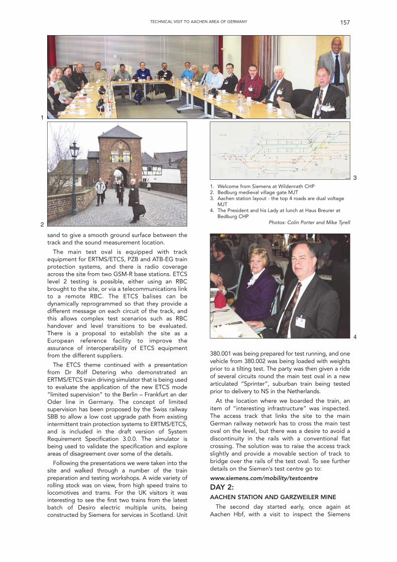
sand to give a smooth ground surface between thetrack and the sound measurement location.
The main test oval is equipped with trackequipment for ERTMS/ETCS, PZB and ATB-EG trainprotection systems, and there is radio coverageacross the site from two GSM-R base stations. ETCSlevel 2 testing is possible, either using an RBCbrought to the site, or via a telecommunications linkto a remote RBC. The ETCS balises can bedynamically reprogrammed so that they provide adifferent message on each circuit of the track, andthis allows complex test scenarios such as RBChandover and level transitions to be evaluated.There is a proposal to establish the site as aEuropean reference facility to improve theassurance of interoperability of ETCS equipmentfrom the different suppliers.
The ETCS theme continued with a presentationfrom Dr Rolf Detering who demonstrated anERTMS/ETCS train driving simulator that is being usedto evaluate the application of the new ETCS mode“limited supervision” to the Berlin – Frankfurt an derOder line in Germany. The concept of limitedsupervision has been proposed by the Swiss railwaySBB to allow a low cost upgrade path from existingintermittent train protection systems to ERTMS/ETCS,and is included in the draft version of SystemRequirement Specification 3.0.0. The simulator isbeing used to validate the specification and exploreareas of disagreement over some of the details.
Following the presentations we were taken into thesite and walked through a number of the trainpreparation and testing workshops. A wide variety ofrolling stock was on view, from high speed trains tolocomotives and trams. For the UK visitors it wasinteresting to see the first two trains from the latestbatch of Desiro electric multiple units, beingconstructed by Siemens for services in Scotland. Unit
380.001 was being prepared for test running, and onevehicle from 380.002 was being loaded with weightsprior to a tilting test. The party was then given a rideof several circuits round the main test oval in a newarticulated “Sprinter”, suburban train being testedprior to delivery to NS in the Netherlands.
At the location where we boarded the train, anitem of “interesting infrastructure” was inspected.The access track that links the site to the mainGerman railway network has to cross the main testoval on the level, but there was a desire to avoid adiscontinuity in the rails with a conventional flatcrossing. The solution was to raise the access trackslightly and provide a movable section of track tobridge over the rails of the test oval. To see furtherdetails on the Siemen’s test centre go to:
www.siemens.com/mobility/testcentre
DAY 2:AACHEN STATION AND GARZWEILER MINE
The second day started early, once again atAachen Hbf, with a visit to inspect the Siemens
157TECHNICAL VISIT TO AACHEN AREA OF GERMANY
1. Welcome from Siemens at Wildenrath CHP2. Bedburg medieval village gate MJT3. Aachen station layout - the top 4 roads are dual voltage
MJT4. The President and his Lady at lunch at Haus Breurer at
Bedburg CHPPhotos: Colin Porter and Mike Tyrell
3
4
1
2
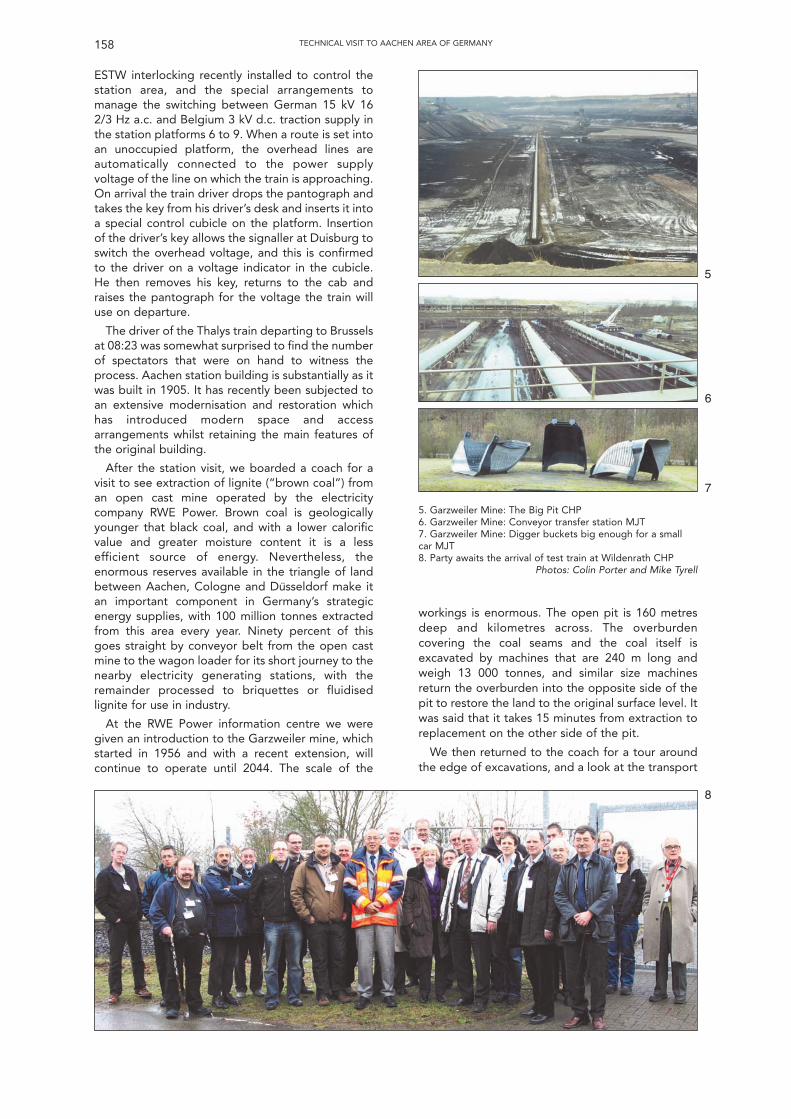
ESTW interlocking recently installed to control thestation area, and the special arrangements tomanage the switching between German 15 kV 162/3 Hz a.c. and Belgium 3 kV d.c. traction supply inthe station platforms 6 to 9. When a route is set intoan unoccupied platform, the overhead lines areautomatically connected to the power supplyvoltage of the line on which the train is approaching.On arrival the train driver drops the pantograph andtakes the key from his driver’s desk and inserts it intoa special control cubicle on the platform. Insertionof the driver’s key allows the signaller at Duisburg toswitch the overhead voltage, and this is confirmedto the driver on a voltage indicator in the cubicle.He then removes his key, returns to the cab andraises the pantograph for the voltage the train willuse on departure.
The driver of the Thalys train departing to Brusselsat 08:23 was somewhat surprised to find the numberof spectators that were on hand to witness theprocess. Aachen station building is substantially as itwas built in 1905. It has recently been subjected toan extensive modernisation and restoration whichhas introduced modern space and accessarrangements whilst retaining the main features ofthe original building.
After the station visit, we boarded a coach for avisit to see extraction of lignite (“brown coal”) froman open cast mine operated by the electricitycompany RWE Power. Brown coal is geologicallyyounger that black coal, and with a lower calorificvalue and greater moisture content it is a lessefficient source of energy. Nevertheless, theenormous reserves available in the triangle of landbetween Aachen, Cologne and Dusseldorf make itan important component in Germany’s strategicenergy supplies, with 100 million tonnes extractedfrom this area every year. Ninety percent of thisgoes straight by conveyor belt from the open castmine to the wagon loader for its short journey to thenearby electricity generating stations, with theremainder processed to briquettes or fluidisedlignite for use in industry.
At the RWE Power information centre we weregiven an introduction to the Garzweiler mine, whichstarted in 1956 and with a recent extension, willcontinue to operate until 2044. The scale of the
workings is enormous. The open pit is 160 metresdeep and kilometres across. The overburdencovering the coal seams and the coal itself isexcavated by machines that are 240 m long andweigh 13 000 tonnes, and similar size machinesreturn the overburden into the opposite side of thepit to restore the land to the original surface level. Itwas said that it takes 15 minutes from extraction toreplacement on the other side of the pit.
We then returned to the coach for a tour aroundthe edge of excavations, and a look at the transport
158 TECHNICAL VISIT TO AACHEN AREA OF GERMANY
5. Garzweiler Mine: The Big Pit CHP6. Garzweiler Mine: Conveyor transfer station MJT7. Garzweiler Mine: Digger buckets big enough for a smallcar MJT8. Party awaits the arrival of test train at Wildenrath CHP
Photos: Colin Porter and Mike Tyrell
5
6
7
8

arrangements including kilometres of conveyorbelts, and a railway system that connects Garzwelierand two other mines to the lignite processingplants. As the railway does not need to beinteroperable the locomotives and wagons areallowed to operate with a 35 tonne axleload. Therailway is electrified and the locomotives areequipped with an additional side-mountedpantograph to allow them to collect traction powerwhilst running underneath the coal loading bunkers.For further information: www.rwe.com/ web/cms/mediablob/en/247478/data/235578/34705/rwepower-ag/media-center/lignite/blob.pdf
The scale of the mining operation has meantenormous disruption to the landscape. The recentextension to the Garzweiler mining area will require
the closure and subsequent rebuilding of a railway,two motorways, and the relocation of severalvillages to new sites. Our tour finished with a visit tothe relocated village of Königshoven with anattractive variety of houses in local styles,constructed by the former villagers using theircompensation money, and a new church thatincorporates the altar from the church in the oldvillage. On route to lunch the party visited theoriginal quarter of the village of Bedburg to view themedieval gatehouse and Village Street. The visitended with a typical local lunch of meat anddumplings at restaurant Haus Breurer in the oldervillage of Bedburg that has survived the mining, andthe coach returned the party to Aachen for theparticipants to make their way home or spend somemore time in the city.
159TECHNICAL VISIT TO AACHEN AREA OF GERMANY
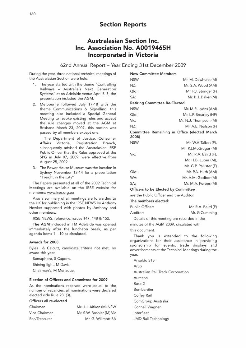
160
During the year, three national technical meetings ofthe Australasian Section were held.
1. The year started with the theme “ControllingRailways – Australia’s Next GenerationSystems” at an Adelaide venue April 3–5, thepresentation included the AGM.
2. Melbourne followed July 17-18 with thetheme Communications & Signalling, thismeeting also included a Special GeneralMeeting to revoke existing rules and acceptthe rule changes moved at the AGM atBrisbane March 23, 2007, this motion waspassed by all members except one.
The Department of Justice, ConsumerAffairs Victoria, Registration Branch,subsequently advised the Australasian IRSEPublic Officer that the Rules approved at theSPG in July 07, 2009, were effective fromAugust 25, 2009
3. The Power House Museum was the location inSydney November 13-14 for a presentation“Freight in the City”
The Papers presented at all of the 2009 TechnicalMeetings are available on the IRSE website formembers: www.irse.org.au
Also a summary of all meetings are forwarded tothe UK for publishing in the IRSE NEWS by AnthonyHowker supported with photos by Anthony andother members.
IRSE NEWS, reference, issues 147, 148 & 152.
The AGM included in TM Adelaide was openedimmediately after the luncheon break, as peragenda items 1 – 10 as circulated.
Awards for 2008.
Byles & Calcutt, candidate criteria not met, noaward this year.
Semaphore, S Caporn.
Shining light, M Davis,
Chairman’s, M Menadue.
Election of Officers and Committee for 2009
As the nominations received were equal to thenumber of vacancies, all nominations were declaredelected vide Rule 23. (3).
Officers all re-elected
Chairman Mr. J.J. Aitken (M) NSW
Vice Chairman Mr. S.W. Boshier (M) Vic
Sec/Treasurer Mr. G. Willmott SA
New Committee Members
NSW: Mr. M. Dewhurst (M)
NZ: Mr. S.A. Wood (AM)
Qld: Mr. P.J. Stringer (F)
SA: Mr. B.J. Baker (M)
Retiring Committee Re-Elected
NSW: Mr. M.R. Lyons (AM)
Qld: Mr. L.F. Brearley (HF)
Vic: Mr. N.J. Thompson (M)
NZ: Mr. A.E. Neilson (F)
Committee Remaining in Office (elected March2008)
NSW: Mr. W.V. Talbot (F),
Mr. P.J.McGregor (M)
Vic: Mr. R.A. Baird (F),
Mr. H.B. Luber (M),
Mr. G.P. Pallister (F)
Qld: Mr. P.A. Huth (AM)
WA: Mr. A.M. Godber (M)
SA: Mr. M.A. Forbes (M)
Officers to be Elected by Committee
are the Public Officer and the Auditor.
The members elected:
Public Officer: Mr. R.A. Baird (F)
Auditor: Mr. G Cumming
Details of this meeting are recorded in the
minutes of the AGM 2009, circulated with
this document.
Thank you is extended to the followingorganizations for their assistance in providingsponsorship for events, trade displays andadvertisements at the Technical Meetings during theyear.
Ansaldo STS
Arup
Australian Rail Track Corporation
Aurecon
Base 2
Bombardier
Coffey Rail
ComGroup Australia
Connell Wagner
Interfleet
JMD Rail Technology
Australasian Section Inc.Inc. Association No. A0019465H
Incorporated in Victoria
62nd Annual Report – Year Ending 31st December 2009
Section Reports
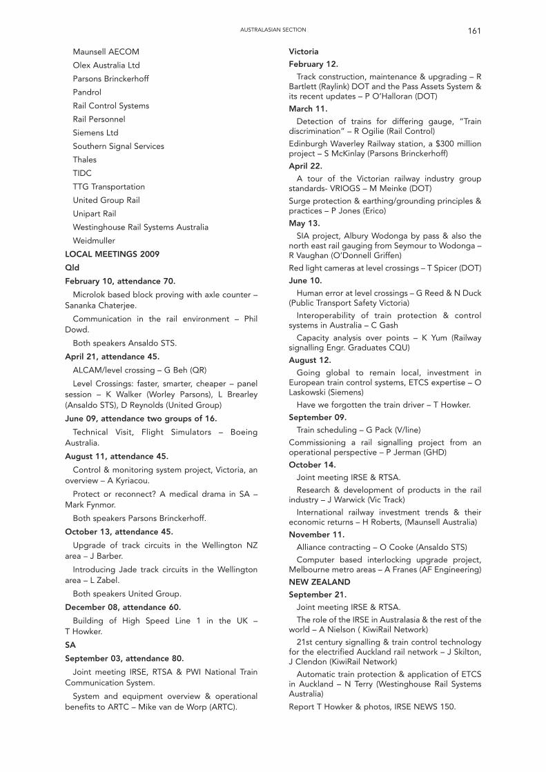
Maunsell AECOM
Olex Australia Ltd
Parsons Brinckerhoff
Pandrol
Rail Control Systems
Rail Personnel
Siemens Ltd
Southern Signal Services
Thales
TIDC
TTG Transportation
United Group Rail
Unipart Rail
Westinghouse Rail Systems Australia
Weidmuller
LOCAL MEETINGS 2009
Qld
February 10, attendance 70.
Microlok based block proving with axle counter –Sananka Chaterjee.
Communication in the rail environment – PhilDowd.
Both speakers Ansaldo STS.
April 21, attendance 45.
ALCAM/level crossing – G Beh (QR)
Level Crossings: faster, smarter, cheaper – panelsession – K Walker (Worley Parsons), L Brearley(Ansaldo STS), D Reynolds (United Group)
June 09, attendance two groups of 16.
Technical Visit, Flight Simulators – BoeingAustralia.
August 11, attendance 45.
Control & monitoring system project, Victoria, anoverview – A Kyriacou.
Protect or reconnect? A medical drama in SA –Mark Fynmor.
Both speakers Parsons Brinckerhoff.
October 13, attendance 45.
Upgrade of track circuits in the Wellington NZarea – J Barber.
Introducing Jade track circuits in the Wellingtonarea – L Zabel.
Both speakers United Group.
December 08, attendance 60.
Building of High Speed Line 1 in the UK – T Howker.
SA
September 03, attendance 80.
Joint meeting IRSE, RTSA & PWI National TrainCommunication System.
System and equipment overview & operationalbenefits to ARTC – Mike van de Worp (ARTC).
Victoria
February 12.
Track construction, maintenance & upgrading – RBartlett (Raylink) DOT and the Pass Assets System &its recent updates – P O’Halloran (DOT)
March 11.
Detection of trains for differing gauge, “Traindiscrimination” – R Ogilie (Rail Control)
Edinburgh Waverley Railway station, a $300 millionproject – S McKinlay (Parsons Brinckerhoff)
April 22.
A tour of the Victorian railway industry groupstandards- VRIOGS – M Meinke (DOT)
Surge protection & earthing/grounding principles &practices – P Jones (Erico)
May 13.
SIA project, Albury Wodonga by pass & also thenorth east rail gauging from Seymour to Wodonga –R Vaughan (O’Donnell Griffen)
Red light cameras at level crossings – T Spicer (DOT)
June 10.
Human error at level crossings – G Reed & N Duck(Public Transport Safety Victoria)
Interoperability of train protection & controlsystems in Australia – C Gash
Capacity analysis over points – K Yum (Railwaysignalling Engr. Graduates CQU)
August 12.
Going global to remain local, investment inEuropean train control systems, ETCS expertise – OLaskowski (Siemens)
Have we forgotten the train driver – T Howker.
September 09.
Train scheduling – G Pack (V/line)
Commissioning a rail signalling project from anoperational perspective – P Jerman (GHD)
October 14.
Joint meeting IRSE & RTSA.
Research & development of products in the railindustry – J Warwick (Vic Track)
International railway investment trends & theireconomic returns – H Roberts, (Maunsell Australia)
November 11.
Alliance contracting – O Cooke (Ansaldo STS)
Computer based interlocking upgrade project,Melbourne metro areas – A Franes (AF Engineering)
NEW ZEALAND
September 21.
Joint meeting IRSE & RTSA.
The role of the IRSE in Australasia & the rest of theworld – A Nielson ( KiwiRail Network)
21st century signalling & train control technologyfor the electrified Auckland rail network – J Skilton,J Clendon (KiwiRail Network)
Automatic train protection & application of ETCSin Auckland – N Terry (Westinghouse Rail SystemsAustralia)
Report T Howker & photos, IRSE NEWS 150.
AUSTRALASIAN SECTION 161
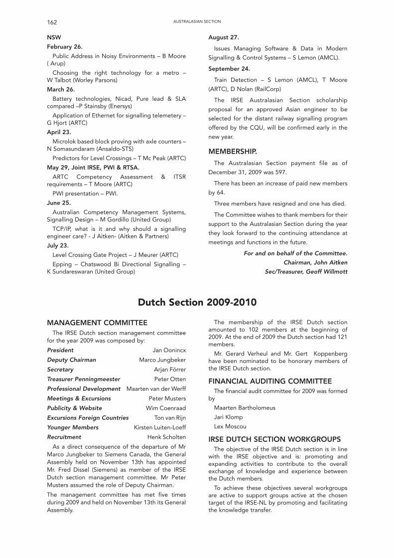
NSW
February 26.
Public Address in Noisy Environments – B Moore ( Arup)
Choosing the right technology for a metro – W Talbot (Worley Parsons)
March 26.
Battery technologies, Nicad, Pure lead & SLAcompared –P Stainsby (Enersys)
Application of Ethernet for signalling telemetery –G Hjort (ARTC)
April 23.
Microlok based block proving with axle counters –N Somasundaram (Ansaldo-STS)
Predictors for Level Crossings – T Mc Peak (ARTC)
May 29, Joint IRSE, PWI & RTSA.
ARTC Competency Assessment & ITSRrequirements – T Moore (ARTC)
PWI presentation – PWI.
June 25.
Australian Competency Management Systems,Signalling Design – M Gordillo (United Group)
TCP/IP, what is it and why should a signallingengineer care? - J Aitken- (Aitken & Partners)
July 23.
Level Crossing Gate Project – J Meurer (ARTC)
Epping – Chatswood Bi Directional Signalling – K Sundareswaran (United Group)
August 27.
Issues Managing Software & Data in Modern
Signalling & Control Systems – S Lemon (AMCL).
September 24.
Train Detection – S Lemon (AMCL), T Moore
(ARTC), D Nolan (RailCorp)
The IRSE Australasian Section scholarship
proposal for an approved Asian engineer to be
selected for the distant railway signalling program
offered by the CQU, will be confirmed early in the
new year.
MEMBERSHIP.
The Australasian Section payment file as of
December 31, 2009 was 597.
There has been an increase of paid new members
by 64.
Three members have resigned and one has died.
The Committee wishes to thank members for their
support to the Australasian Section during the year
they look forward to the continuing attendance at
meetings and functions in the future.
For and on behalf of the Committee.
Chairman, John Aitken
Sec/Treasurer, Geoff Willmott
AUSTRALASIAN SECTION162
Dutch Section 2009-2010
MANAGEMENT COMMITTEEThe IRSE Dutch section management committee
for the year 2009 was composed by:
President Jan Oonincx
Deputy Chairman Marco Jungbeker
Secretary Arjan Förrer
Treasurer Penningmeester Peter Otten
Professional Development Maarten van der Werff
Meetings & Excursions Peter Musters
Publicity & Website Wim Coenraad
Excursions Foreign Countries Ton van Rijn
Younger Members Kirsten Luiten-Loeff
Recruitment Henk Scholten
As a direct consequence of the departure of MrMarco Jungbeker to Siemens Canada, the GeneralAssembly held on November 13th has appointedMr. Fred Dissel (Siemens) as member of the IRSEDutch section management committee. Mr PeterMusters assumed the role of Deputy Chairman.
The management committee has met five timesduring 2009 and held on November 13th its GeneralAssembly.
The membership of the IRSE Dutch sectionamounted to 102 members at the beginning of2009. At the end of 2009 the Dutch section had 121members.
Mr. Gerard Verheul and Mr. Gert Koppenberghave been nominated to be honorary members ofthe IRSE Dutch section.
FINANCIAL AUDITING COMMITTEEThe financial audit committee for 2009 was formed
by
Maarten Bartholomeus
Jari Klomp
Lex Moscou
IRSE DUTCH SECTION WORKGROUPSThe objective of the IRSE Dutch section is in line
with the IRSE objective and is: promoting andexpanding activities to contribute to the overallexchange of knowledge and experience betweenthe Dutch members.
To achieve these objectives several workgroupsare active to support groups active at the chosentarget of the IRSE-NL by promoting and facilitatingthe knowledge transfer.
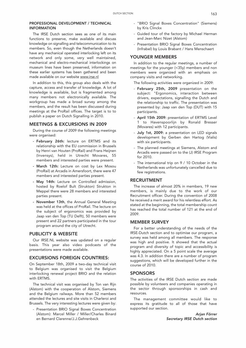
PROFESSIONAL DEVELOPMENT / TECHNICALINFORMATION
The IRSE Dutch section sees as one of its mainfunctions to preserve, make available and discussknowledge on signalling and telecommunication to itsmembers. So, even though the Netherlands doesn’thave any mechanical operated interlocking left on itsnetwork and only some, very well maintained,mechanical and electro-mechanical interlockings onmuseum lines have been preserved, information onthese earlier systems has been gathered and beenmade available on our website www.irse.nl
In addition to this, this group also deals with thecapture, access and transfer of knowledge. A lot ofknowledge is available, but is fragmented amongmany members not electronically available. Theworkgroup has made a broad survey among themembers, and the result has been discussed duringmeetings at the ProRail offices. The target is to topublish a paper on Dutch Signalling in 2010.
MEETINGS & EXCURSIONS IN 2009During the course of 2009 the following meetings
were organised:
- February 26th: lecture on ERTMS and itsrelationship with the EU commission in Brusselsby Henri van Houten (ProRail) and Frans Heijnen(Invensys), held in Utrecht Movares, 55members and interested parties were present.
- March 12th: Lecture on cost by Lex Mosou(ProRail) at Arcadis in Amersfoort, there were 47members and interested parties present.
- May 14th: Lecture on Controlled admission,hosted by Roelof Bult (Strukton) Strukton inMeppel there were 28 members and interestedparties present.
- November 13th, the Annual General Meetingwas held at the offices of ProRail. The lecture onthe subject of ergonomics was provided byJaap van den Top (TU Delft), 50 members werepresent and 22 partners participated in the tourprogram around the city of Utrecht.
PUBLICITY & WEBSITEOur IRSE.NL website was updated on a regular
basis. This year also video podcasts of thepresentations were made available.
EXCURSIONS FOREIGN COUNTRIES:On September 18th, 2009 a two-day technical visitto Belgium was organised to visit the Belgiuminterlocking renewal project BRIO and the relationwith ERTMS.
The technical visit was organised by Ton van Rijn(Alstom) with the cooperation of Alstom, Siemensand the Belgium railways. More than 52 membersattended the lectures and site visits in Charleroi andBrussels. The very interesting lectures were given by:
- Presentation BRIO Signal Boxes Concentration(Alstom): Marcel Miller / Miller/Charles Binarden Bernard Clarenne/J.J.Gehrenbeck
- "BRIO Signal Boxes Concentration" (Siemens)by Kris Clinckx
- Guided tour of the factory by Michael Hermanand Jean-Marc Nizet (Alstom)
- Presentation BRIO Signal Boxes Concentration(Infrabel) by Louis Brabant / Hans Menschaert
YOUNGER MEMBERSIn addition to the regular meetings, a number of
meetings for the younger (<35y) members and nonmembers were organized with an emphasis oncompany visits and networking.
The following activities were organized in 2009:
- February 25th, 2009 presentation on thesubject: "Ergonomics, interaction betweendrivers, expectations, signalling the Dutch andthe relationship to traffic. The presentation waspresented by: Jaap van den Top (DUT) with 15participants.
- April 15th 2009: presentation of ERTMS Level1 to Havenspoorlijn by Ronald Bresser(Movares) with 12 participants.
- July 1st, 2009: a presentation on LED signalsdevelopment by Gerben den Hartog (Vialis)with six participants.
- The planned meetings at Siemens, Alstom andArcadis were passed on to the (J) IRSE Programfor 2010.
- The international trip on 9 / 10 October in theNetherlands was unfortunately cancelled due tofew registrations.
RECRUITMENTThe increase of almost 20% in members, 19 new
members, is mainly due to the work of ourRecruitment officer. During the convention of 2008he received a merit award for his relentless effort. Asstated at the beginning, the total membership counthas reached the total number of 121 at the end of2009.
MEMBER SURVEY For a better understanding of the needs of the
IRSE-Dutch section and to optimise our program, asurvey was held among all members. The responsewas high and positive. It showed that the actualprogram and diversity of topic and accessibility ishighly appreciated. On a 5 point scale the averagewas 4.3. In addition there are a number of programsuggestions, which will be developed further in thecourse of 2010.
SPONSORS The activities of the IRSE Dutch section are madepossible by volunteers and companies operating inthe sector through sponsorships in cash andresources.
The management committee would like toexpress its gratitude to all of those that havesupported our section.
Arjan Förrer Secretary IRSE Dutch section
163DUTCH SECTION
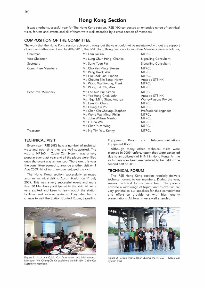
TECHNICAL VISITEvery year, IRSE (HK) hold a number of technical
visits and each time they are well supported. Thevisit to NP360 – Cable Car System, was a verypopular event last year and all the places were filledonce the event was announced. Therefore, this yearthe committee agreed to arrange another visit on 1Aug 2009. All of our members enjoyed the visit.
The Hong Kong section successfully arrangedanother technical visit to Austin Station on 11 July2009. This was a very successful event and morethan 30 Members participated in the visit. All werevery excited and keen to learn about the stationfacilities and railway systems. They also had achance to visit the Station Control Room, Signalling
Equipment Room and TelecommunicationsEquipment Room.
Although many other technical visits wereplanned in 2009, unfortunately they were cancelleddue to an outbreak of H1N1 in Hong Kong. All thevisits have now been rescheduled to be held in thesecond half of 2010.
TECHNICAL FORUMThe IRSE Hong Kong section regularly delivers
technical forums to our members. During the year,several technical forums were held. The paperscovered a wide range of topics, and as ever we arevery grateful to our speakers for their commitmentand effort to provide us with high qualitypresentations. All forums were well attended.
164
Hong Kong SectionIt was another successful year for The Hong Kong session. IRSE (HK) conducted an extensive range of technical
visits, forums and events and all of them were well attended by a cross-section of members.
COMPOSITION OF THE COMMITTEEThe work that the Hong Kong session achieves throughout the year could not be maintained without the supportof our committee members. In 2009/2010, the IRSE Hong Kong Section – Committee Members were as follows,
Chairman Mr. Lam Lai Yin MTRCL
Vice Chairman Mr. Lung Chun Pong, Charles Signalling Consultant
Secretary Mr. Sung Yuen Fat Signalling Consultant
Committee Members Mr. Cho Yan Ming, Steven MTRCLMr. Pang Kwok Wai MTRCLMr. Hui Fook Lun, Francis MTRCLMr. Cheung Nin Sang, Henry Ansaldo STS HKMr. Wong Wai Kwong, Frank MTRCLMr. Wong Tak Chi, Alex MTRCL
Executive Members Mr. Lee Kun Pui, Simon MTRCLMr. Yee Hung Choi, John Ansaldo STS HKMs. Ngai Ming Shan, Anthea WorleyParsons Pty LtdMr. Lam Kin Chung MTRCLMr. Leung Kin Po MTRCLMr. Chan Chi Cheung, Stephen Professional EngineerMr. Wong Wai Ming, Philip MTRCLMr. John William Manho MTRCLMr. Li Chu Wai MTRCLMr. Chan Yuet Wing MTRCL
Treasurer Mr. Ng Tim Yau, Kenny MTRCL
Figure 1 Assistant Cable Car Operations and MaintenanceManager - Mr. Chung Chi Kit explained the NP 360 - Cable CarSystem to members
Figure 2 Group Photo taken during the NP360 - Cable CarSystem Visit
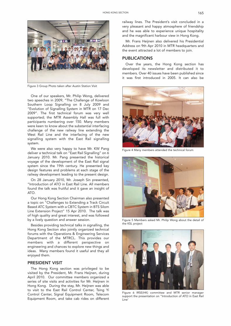
One of our speakers, Mr. Philip Wong, deliveredtwo speeches in 2009, “The Challenge of KowloonSouthern Loop Signalling on 8 July 2009 and“Evolution of Signalling System in MTR on 17 Dec2009”. The first technical forum was very wellsupported; the MTR Assembly Hall was full withparticipants numbering over 150. Many memberswere keen to know about the substantial interfacingchallenge of the new railway line extending theWest Rail Line and the interfacing of the newsignalling system with the East Rail signallingsystem.
We were also very happy to have Mr. KW Pangdeliver a technical talk on “East Rail Signalling” on 6January 2010. Mr. Pang presented the historicalvoyage of the development of the East Rail signalsystem since the 19th century. He presented keydesign features and problems at each stage of therailway development leading to the present design.
On 28 January 2010, Mr. Joseph Sin presented,“Introduction of ATO in East Rail Line. All membersfound the talk was fruitful and it gave an insight ofATO.
Our Hong Kong Section Chairman also presenteda topic on "Challenges to Extending a Track CircuitBased ATC System with a CBTC System in BTS SilomLine Extension Project" 15 Apr 2010. The talk wasof high quality and great interest, and was followedby a lively question and answer session.
Besides providing technical talks in signalling, theHong Kong Section also jointly organized technicalforums with the Operations & Engineering ServicesDepartment of the MTRCL. This provides ourmembers with a different perspective onengineering and chances to explore new things andideas. Many members found it useful and they allenjoyed them.
PRESIDENT VISITThe Hong Kong section was privileged to be
visited by the President, Mr. Frans Heijnen, duringApril 2010. Our committee members organized aseries of site visits and activities for Mr. Heijnen inHong Kong. During the stay, Mr. Heijnen was ableto visit to the East Rail Control Center, Tsing YiControl Center, Signal Equipment Room, TelecomEquipment Room, and take cab rides on different
railway lines. The President’s visit concluded in avery pleasant and happy atmosphere of friendshipand he was able to experience unique hospitalityand the magnificent harbour view in Hong Kong.
Mr. Frans Heijnen also delivered his PresidentialAddress on 9th Apr 2010 in MTR headquarters andthe event attracted a lot of members to join.
PUBLICATIONSOver the years, the Hong Kong section has
developed its newsletter and distributed it tomembers. Over 40 issues have been published sinceit was first introduced in 2005. It can also be
165HONG KONG SECTION
Figure 3 Group Photo taken after Austin Station Visit
Figure 5 Members asked Mr. Philip Wong about the detail ofthe KSL project
Figure 6 IRSE(HK) committee and MTR senior managersupport the presentation on “Introduction of ATO in East RailLine’
Figure 4 Many members attended the technical forum
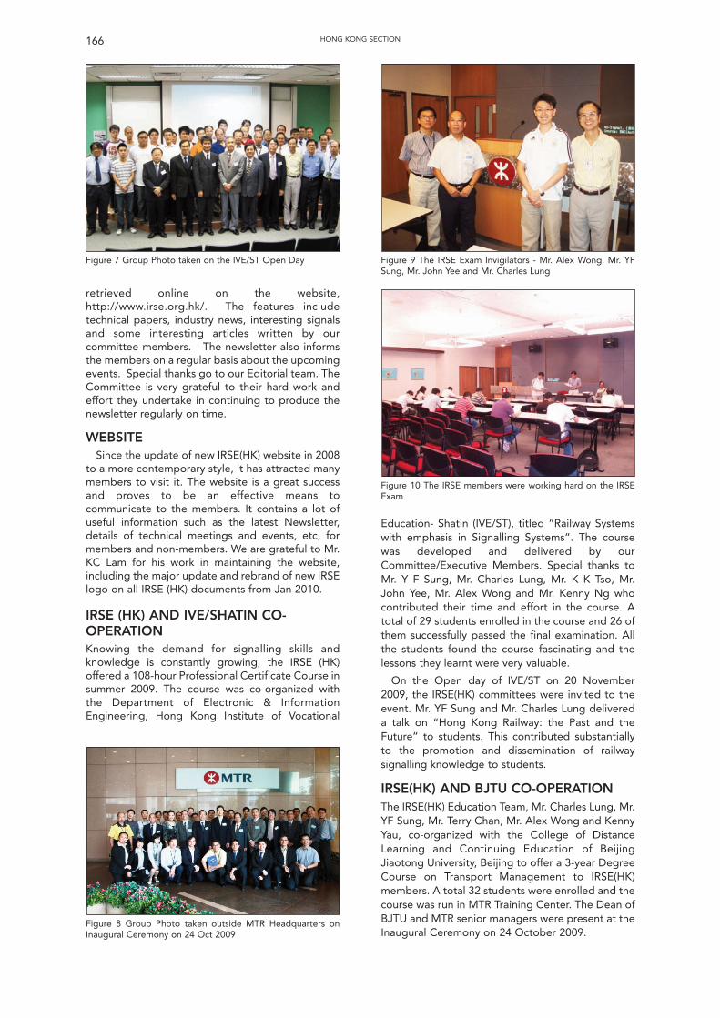
retrieved online on the website,http://www.irse.org.hk/. The features includetechnical papers, industry news, interesting signalsand some interesting articles written by ourcommittee members. The newsletter also informsthe members on a regular basis about the upcomingevents. Special thanks go to our Editorial team. TheCommittee is very grateful to their hard work andeffort they undertake in continuing to produce thenewsletter regularly on time.
WEBSITESince the update of new IRSE(HK) website in 2008
to a more contemporary style, it has attracted manymembers to visit it. The website is a great successand proves to be an effective means tocommunicate to the members. It contains a lot ofuseful information such as the latest Newsletter,details of technical meetings and events, etc, formembers and non-members. We are grateful to Mr.KC Lam for his work in maintaining the website,including the major update and rebrand of new IRSElogo on all IRSE (HK) documents from Jan 2010.
IRSE (HK) AND IVE/SHATIN CO-OPERATIONKnowing the demand for signalling skills andknowledge is constantly growing, the IRSE (HK)offered a 108-hour Professional Certificate Course insummer 2009. The course was co-organized withthe Department of Electronic & InformationEngineering, Hong Kong Institute of Vocational
Education- Shatin (IVE/ST), titled “Railway Systemswith emphasis in Signalling Systems”. The coursewas developed and delivered by ourCommittee/Executive Members. Special thanks toMr. Y F Sung, Mr. Charles Lung, Mr. K K Tso, Mr.John Yee, Mr. Alex Wong and Mr. Kenny Ng whocontributed their time and effort in the course. Atotal of 29 students enrolled in the course and 26 ofthem successfully passed the final examination. Allthe students found the course fascinating and thelessons they learnt were very valuable.
On the Open day of IVE/ST on 20 November2009, the IRSE(HK) committees were invited to theevent. Mr. YF Sung and Mr. Charles Lung delivereda talk on “Hong Kong Railway: the Past and theFuture” to students. This contributed substantiallyto the promotion and dissemination of railwaysignalling knowledge to students.
IRSE(HK) AND BJTU CO-OPERATIONThe IRSE(HK) Education Team, Mr. Charles Lung, Mr.YF Sung, Mr. Terry Chan, Mr. Alex Wong and KennyYau, co-organized with the College of DistanceLearning and Continuing Education of BeijingJiaotong University, Beijing to offer a 3-year DegreeCourse on Transport Management to IRSE(HK)members. A total 32 students were enrolled and thecourse was run in MTR Training Center. The Dean ofBJTU and MTR senior managers were present at theInaugural Ceremony on 24 October 2009.
166 HONG KONG SECTION
Figure 7 Group Photo taken on the IVE/ST Open Day Figure 9 The IRSE Exam Invigilators - Mr. Alex Wong, Mr. YFSung, Mr. John Yee and Mr. Charles Lung
Figure 10 The IRSE members were working hard on the IRSEExam
Figure 8 Group Photo taken outside MTR Headquarters onInaugural Ceremony on 24 Oct 2009
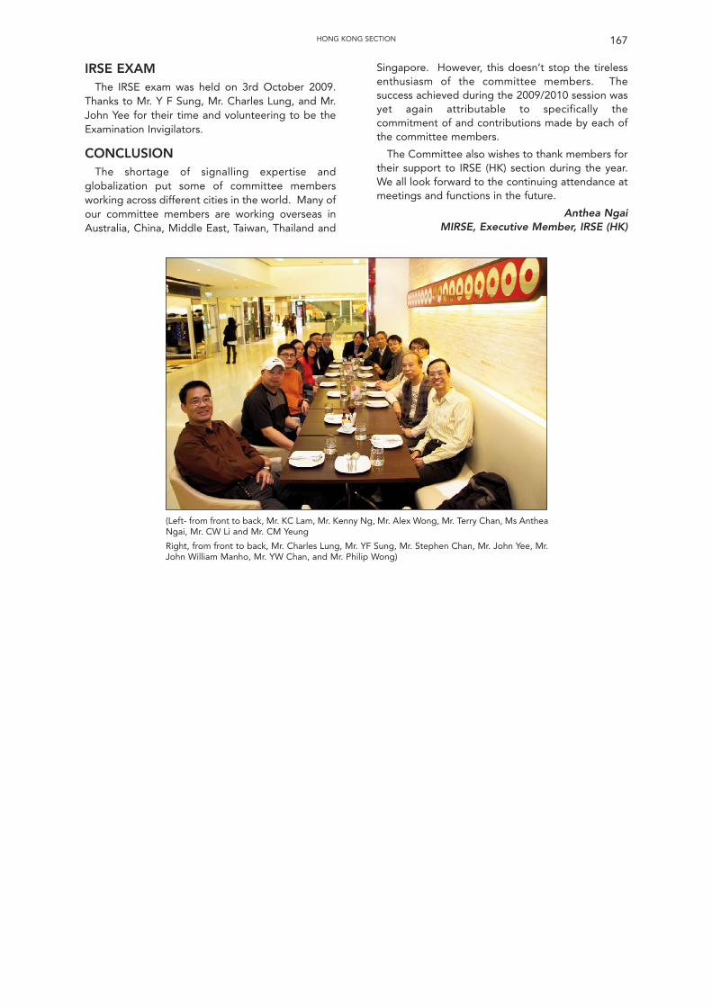
IRSE EXAMThe IRSE exam was held on 3rd October 2009.
Thanks to Mr. Y F Sung, Mr. Charles Lung, and Mr.John Yee for their time and volunteering to be theExamination Invigilators.
CONCLUSION The shortage of signalling expertise and
globalization put some of committee membersworking across different cities in the world. Many ofour committee members are working overseas inAustralia, China, Middle East, Taiwan, Thailand and
Singapore. However, this doesn’t stop the tirelessenthusiasm of the committee members. Thesuccess achieved during the 2009/2010 session wasyet again attributable to specifically thecommitment of and contributions made by each ofthe committee members.
The Committee also wishes to thank members fortheir support to IRSE (HK) section during the year.We all look forward to the continuing attendance atmeetings and functions in the future.
Anthea NgaiMIRSE, Executive Member, IRSE (HK)
167HONG KONG SECTION
(Left- from front to back, Mr. KC Lam, Mr. Kenny Ng, Mr. Alex Wong, Mr. Terry Chan, Ms AntheaNgai, Mr. CW Li and Mr. CM Yeung
Right, from front to back, Mr. Charles Lung, Mr. YF Sung, Mr. Stephen Chan, Mr. John Yee, Mr.John William Manho, Mr. YW Chan, and Mr. Philip Wong)
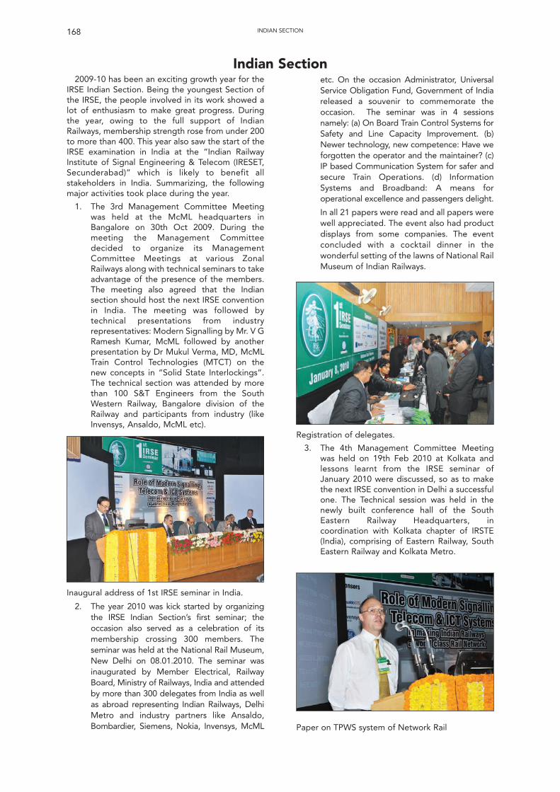
2009-10 has been an exciting growth year for theIRSE Indian Section. Being the youngest Section ofthe IRSE, the people involved in its work showed alot of enthusiasm to make great progress. Duringthe year, owing to the full support of IndianRailways, membership strength rose from under 200to more than 400. This year also saw the start of theIRSE examination in India at the “Indian RailwayInstitute of Signal Engineering & Telecom (IRESET,Secunderabad)” which is likely to benefit allstakeholders in India. Summarizing, the followingmajor activities took place during the year.
1. The 3rd Management Committee Meetingwas held at the McML headquarters inBangalore on 30th Oct 2009. During themeeting the Management Committeedecided to organize its ManagementCommittee Meetings at various ZonalRailways along with technical seminars to takeadvantage of the presence of the members.The meeting also agreed that the Indiansection should host the next IRSE conventionin India. The meeting was followed bytechnical presentations from industryrepresentatives: Modern Signalling by Mr. V GRamesh Kumar, McML followed by anotherpresentation by Dr Mukul Verma, MD, McMLTrain Control Technologies (MTCT) on thenew concepts in “Solid State Interlockings”.The technical section was attended by morethan 100 S&T Engineers from the SouthWestern Railway, Bangalore division of theRailway and participants from industry (likeInvensys, Ansaldo, McML etc).
etc. On the occasion Administrator, UniversalService Obligation Fund, Government of Indiareleased a souvenir to commemorate theoccasion. The seminar was in 4 sessionsnamely: (a) On Board Train Control Systems forSafety and Line Capacity Improvement. (b)Newer technology, new competence: Have weforgotten the operator and the maintainer? (c)IP based Communication System for safer andsecure Train Operations. (d) InformationSystems and Broadband: A means foroperational excellence and passengers delight.
In all 21 papers were read and all papers werewell appreciated. The event also had productdisplays from some companies. The eventconcluded with a cocktail dinner in thewonderful setting of the lawns of National RailMuseum of Indian Railways.
168 INDIAN SECTION
Indian Section
Inaugural address of 1st IRSE seminar in India.
2. The year 2010 was kick started by organizingthe IRSE Indian Section’s first seminar; theoccasion also served as a celebration of itsmembership crossing 300 members. Theseminar was held at the National Rail Museum,New Delhi on 08.01.2010. The seminar wasinaugurated by Member Electrical, RailwayBoard, Ministry of Railways, India and attendedby more than 300 delegates from India as wellas abroad representing Indian Railways, DelhiMetro and industry partners like Ansaldo,Bombardier, Siemens, Nokia, Invensys, McML
Registration of delegates.
3. The 4th Management Committee Meetingwas held on 19th Feb 2010 at Kolkata andlessons learnt from the IRSE seminar ofJanuary 2010 were discussed, so as to makethe next IRSE convention in Delhi a successfulone. The Technical session was held in thenewly built conference hall of the SouthEastern Railway Headquarters, incoordination with Kolkata chapter of IRSTE(India), comprising of Eastern Railway, SouthEastern Railway and Kolkata Metro.
Paper on TPWS system of Network Rail
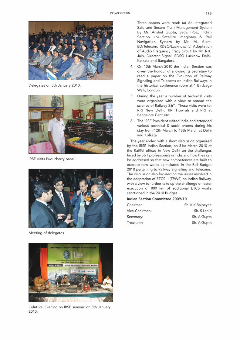
Three papers were read: (a) An integratedSafe and Secure Train Management SystemBy Mr. Anshul Gupta, Secy. IRSE, IndianSection. (b) Satellite Imaginary & RailNavigation System by Mr. M. Alam,ED/Telecom, RDSO/Lucknow. (c) Adoptationof Audio Frequency Tracy circuit by Mr. R.K.Jain, Director Signal, RDSO Lucknow Delhi,Kolkata and Bangalore.
4. On 10th March 2010 the Indian Section wasgiven the honour of allowing its Secretary toread a paper on the Evolution of RailwaySignaling and Telecoms on Indian Railways inthe historical conference room at 1 BirdcageWalk, London.
5. During the year a number of technical visitswere organized with a view to spread thescience of Railway S&T. These visits were to:RRI New Delhi, RRI Howrah and RRI atBangalore Cant etc.
6. The IRSE President visited India and attendedvarious technical & social events during hisstay from 12th March to 18th March at Delhiand Kolkata.
The year ended with a short discussion organizedby the IRSE Indian Section, on 31st March 2010 atthe RailTel offices in New Delhi on the challengesfaced by S&T professionals in India and how they canbe addressed so that new competences are built toexecute new works as included in the Rail Budget2010 pertaining to Railway Signalling and Telecoms.The discussion also focused on the issues involved inthe adaptation of ETCS -I (TPWS) on Indian Railway,with a view to further take up the challenge of fasterexecution of 800 km of additional ETCS workssanctioned in the 2010 Budget.
Indian Section Committee 2009/10
Chairman: Sh. K K Bajpeyee
Vice-Chairman: Sh. S Lahiri
Secretary: Sh. A Gupta
Treasurer: Sh. A Gupta
169INDIAN SECTION
Culutural Evening on IRSE seminar on 8th January2010.
Delegates on 8th January 2010.
IRSE visits Puducherry panel.
Meeting of delegates.
170
The Session has seen a programme whichfeatured the 6th Annual Steam Lunch, one technicalvisit and eight lectures, two in Birmingham, two inDerby and one each in Banbury, Crewe, Manchester,and Preston.
The technical visit was to the recentlycommissioned East Midlands Signalling ControlCentre on the 7th January, which included abackground paper explaining the overallimplementation strategy for the East MidlandsResignalling Schemes, the construction andcommissioning of the control centre and thecommissioning of the first projects into thesignalling centre. The tour of the facilities includedthe equipment rooms, operational floor, trainingfacilities and the incident control room.
The Annual Luncheon and Technical Visit wereheld on the Peak Railway in Derbyshire on Saturday14th June when members and guests had theopportunity to enjoy the line from Matlock toRowsley. The day started with a trip from RowsleySouth Station to Darley Dale Station on the train.The group then enjoyed a leisurely stroll back toRowsley South Station station in glorious sunshinewhile visiting Darley Dale and Church Lane Crossingboxes, and also inspecting one of the point machineinstallations in typical IRSE style. The party thenrejoined the train service at Rowsley South in time tostart the excellent three course meal eaten on thePalatine Dining Train while enjoying the sceneryduring two round trips of the line.
The winter lecture season commenced in Derby inOctober with a talk on Training Requirements givenby Reuben Dakin of Signet Solutions and Craig Kingof Catalis Rail Training. The lecture gave theaudience an insight to the history and structure oftechnical signalling training and also the needs thatmay be required to sustain the highly qualifiedengineers for the future. The lecture finished with atour of the facilities on site.
The second meeting was held in Birmingham inNovember when D Hayward of Signalling SolutionsLimited gave his paper on Smartlock. This paperlooked at the development, acceptance andcommissioning of the system into the UKenvironment and the challenges that where faced.
In December the meeting was held in Crewe andwas addressed by Phil Waddingham and PaulRobertshaw from Invensys Rail who gave a talk titledLevel Crossing Solutions. The lecture looked at theacceptance and commissioning of the WESTeX levelcrossing solution to the UK market.
The New Year started with a return visit to Derbyto the East Midlands Control Centre with apresentation from Dave Scarth of Network Rail. Thepaper and technical visit was well attended withpeople battling through the snow and ice.
The second January meeting was held inManchester. This dealt with Driver AdvisoryInformation for Energy Management and Regulationgiven by Ian Mitchell of Delta Rail which he hadpreviously presented in London.
In February we moved to Banbury for a talk onAxle Counter Applications on the Settle to CarlisleLine (SCAM) given by Steve Moore of Siemens &David Teasdel of Babcock Rail. This presentationwas repeated in March in Preston giving theopportunity for more members local to the projectarea to hear and question the speakers.
In February, a new Midland and North WesternSection tie was launched to celebrate the section’s40th Anniversary.
It is a great pleasure to announce that the Midland& North Western Section Chairman’s Award isawarded to John Phillips. The section and the IRSEhave recognised the work and support that John hasprovided not only to the local section, but to theInstitution as a whole. The work that he undertakeshas put a lot back into the industry, often unpaidand in is own time. On the Severn Valley RailwayJohn not only supports the day to day running of therailway, but also keeps the "traditional" signalling inservice for everyone to enjoy.
I would like to thank the members of theCommittee, in particular our Secretary Bill Redfern,the speakers who provided an interesting selectionof subjects, the companies that supported thesponsorship of the venues and those responsible fortaking an active part with the organisation of theyears events.
IRSE Midland and North WesternSection – 2009/10Committee officers:
Chairman Graham Hill
Vice Chairman Paul DuGuay
Hon. Secretary Bill Redfern
Visits Secretary Ian Allison
Hon. Treasurer Clive Williams
Younger Members Representative Matthew Lupton
MEMBERS OF THE COMMITTEE:Ian AllisonBob BarnardIan BridgesPaul DuGuayBuddhadev Dutta-ChowdhuryIan FuryTapas Halder Peter HalliwellGraham Hill Ian JohnsonMatthew Lupton Ian H MitchellMelvyn NashBill Redfern Clive Williams
Graham HillChairman 2009-10
IRSE Midland and North Western Section
IRSE Midland & North Western Section
171
Minor Railways SectionThe 2009/2010 Committee consists of: -
Chairman Ian James Allison
Vice-Chairman Dave Helliwell
Treasurer Trevor Hodgson
Secretary Martijn Huibers
Committee Stephen ClarkSteve Growcott
Ian HughesRoger Phelps
Mike TyrrellKevin Weston
In its first full year of its existence the MinorRailways Section has organised 4 successful events.
The first event was a 2-day visit to the Paignton &Dartmouth Steam Railway and the South DevonRailway on Saturday and Sunday 26/27 September2009. Some 30 members and guests were present inwhat was a most enjoyable and informative event,with opportunities to study a number of innovativeideas and technological advances put into practicaloperation. On Saturday the day started with astructured safety briefing and overview of therailway signalling and telecommunications systemsemployed by Mr Dave Helliwell. The group thansplit into two groups and departed by special trainfrom Paignton to Goodrington Sands and BritanniaCrossing signal box near Kingswear where the visitwas continued. At Goodrington Sands there wasthe possibility to look at the site of the soon-to-be-commissioned passenger passing loop, sidings andground frame panel, to be controlled by Britanniasignal box via a Westinghouse S3 (Westronic) TDM.This must be a first where such technology has beenused in the Minor Railways world. The relay room onsite was inspected in great detail, having previouslybeen a permanent way building converted for thepurpose. The groups were also briefed on the typesof equipment used and where they have beenlocated on site, due to the nearby coast line and theenvironmental impact regarding corrosion andmaintenance related issues. At Churston, the newreplacement entrance-exit signalling panelconstructed by the railway themselves forinstallation at Britannia Crossing for GoodringtonSands was shown. It was interesting to note thatmany off-the-shelf products were used to constructthe panel, which will operate the Route RelayInterlocking based on the former Western RegionW10K signalling circuit design. Also available forinspection was a hydro-pneumatic point machine,the ground frames for the sidings for the variousworkshops and storage facilities along with theground frame release instrument at Churston. It wasinteresting to note the use of standard bulk-headlights skilfully altered and adjusted to be used as‘OFF’ indicators on both of the platforms. AtBritannia Crossing signal box, Mr David Mabey,Signalling Technician of the railway, gave anoverview of the railway signalling andtelecommunication systems employed on site.There was also ample time to observe the signalman
at the box, which also controlled the level crossingnext to the box for the nearby ferry crossing and thelevel crossing at Kingswear station for the nearbymarina. The railway has no internal telephoneexchange at present and relies upon the Series 600former Western Region telephone concentrator fortrain-to-signal box communication, supplementedby local radio and BT telephones. Key operating andengineering staff are also issued with mobiletelephones as part of a package negotiated with BT.Communications to the Network Rail Signaller atPaignton is via a direct line over the BT network.
On Sunday, the visit continued at the South DevonRailway, where Mr Trevor Hodgson, the SignalEngineer of the railway, invited all members andguests to board the special train from Buckfastleighto Totnes Littlehempston station. With signallingbased on typical GWR practice, the railway hasthree operational signal boxes (Buckfastleigh South,Bishops Bridge and crossing box Staverton) and afurther two non-operational boxes (the originalBuckfastleigh box and Ashburton Junction box).After the required safety briefing, Mr Hodgson gavean overview of the railway signalling andtelecommunications systems employed, after whichthe group visited the site including the new southground frame, the station and Ashburton Junctionsignal box under restoration. At the north end of thesite is the ground frame that currently operates thesignal for the station platform line, along with thepoints to allow locomotive run-round and for thethrough passenger trains that arrive from NetworkRail infrastructure each operating season. AtStaverton station the original 1911 crossing box wasvisited, released from the nearby Bishops Bridgesignal box. The Bishops Bridge signal box andpassenger passing loop were installed andcommissioned in 1999 having preciously beenlocated at Athelney in Somerset, with furtheralterations to the Dock Siding and Staverton levelcrossing installed and commissioned in 2005. Thesignal box itself is fitted with a GWR stud frame andhas a closing lever installed. The block working is byelectric key token (EKT) to Buckfastleigh and bytrain staff (with ticket working for special events) toTotnes. When Bishops Bridge signal box is closed,the railway is operated under the one-engine-in-steam principle with a long-section train staff. Backin Buckfastleigh both the North and South signalboxes were visited as well as the extensivelocomotive engineering facilities. This later is amajor revenue-earner for the railway, undertakingtyre installation and renewal for other railwaycompanies, both mainline and heritage.
The Minor Railways Section would like to thankthe following people who made this event possible:Mr & Mrs Dave Helliwell, Mr David Mabey, Mr PeterRoach, Mr Andrew Pooley, Mr Trevor Hodgson, MrDick Wood and both the Dart Valley Railway and theSouth Devon Railway Association. The sponsors forthis event were: Catalis Railway Training Ltd, DEGSignals Ltd, Green Dragon Rail Ltd, Signet Solutions
172 MINOR RAILWAYS SECTION
Ltd as well as all those individual Members whodonated so generously.
The second event was our Winter TechnicalMeeting, a Seminar on Saturday 7 November 2009at the Kidderminster Railway Museum. This seminarwas a follow-up from the popular seminar held in2005 at the same location. About 70 peopleattended this time with a very broad range ofpresentations. The day started with a welcome byour Chairman and an opening address by PastPresident Mr John Francis, who was our Presidentduring the convention in 2005. The firstpresentation was by Mr John Tilly about HeritageRailway Level Crossings. He discussed the dangersof level crossings and the non-compliance of aseveral level crossings on heritage railways with theregulations. The second presentation was by Mr IanHughes about probably the first signalling projecton a minor railway commissioned under ROGS, anew repeater for a signal on the Ravenglass andEskdale Railway. Using this example, the process ofROGS was explained and it actually does not haveto be a difficult exercise. The third presentation wasby the Section secretary Mr Martijn Huibers. Hepresented the progress so far with the initiative tomake redundant signalling and telecommunicationsequipment from main-line renewal projects andsurplus equipment at heritage railways available forthose who might give it a good home. After thesethree presentations was some time to discuss thesubjects presented so far with the presenters and ashort break for the next session.
The second session of the day started with apresentation by Mr Richard Lemon named“Operations – keep it simple”. He questioned theamount of signalling sometimes found on heritagerailways which, although it does present a sort ofheritage scenery, can make the way the railway isoperated more complex than is necessary. The nextpresentation was about ROGS and SafetyVerification by Mr David Keay, Principal Inspector ofRailways, HMRI. Some practical guidance was givenon what the HMRI will inspect with respect to ROGSand Safety Verification. The last presentation of themorning sessions was from RAIB. Mr Andy Savagetold about what RAIB is and does and what thecurrent ‘track-record’ is for heritage lines. Hefinished with a short description of what happenswhen there is an accident, what the role of the RAIBis and what you should or shouldn’t do yourself.Following another discussion with the presentersthere was an excellent lunch and the possibility tovisit the Kidderminster Railway Museum and thesignalbox and a large signalbox frame next to themuseum.
The afternoon session started with a presentationby Steve Bradbury about the Voice over IPtelephony at the Severn Valley Railway. Thepresentation told all members and guests how thiswas achieved and the challenges faced during theinstallation. For the second presentation by MrCraig Donald another heritage line was visited, thistime the North York Moors Railway. The subject ofthis presentation was renewal of lineside signals.
Several signal renewals were shown with the winterconditions not helping getting to site as well. Thethird presentation was another ‘keep it simple’message, this time about connections to the mainline. Mr John Jenkins took us to the West SomersetRailway where he explained which considerations arailway organisation should take into account whenaiming for a mainline connection. Such a connectionis never cheap and a proper agreement about costsand future maintenance boundaries should be inplace. Another discussion with the presentersclosed this third block of presentations.
The last session of the day started with apresentation about Practical MechanicalInterlocking by Mr Stuart Ward from the SwanageRailway. He discussed a basic method of designinga mechanical interlocking, the things to take intoaccount doing so and some practical advice for theinstallation. The second presentation was an updateon the progress of Peak Rail by Mr Dom Beglin. Thethings that have happened in the last few years werepresented as well as the aims for the years to come.The last presentation of the day was from Mr BillHillier from the Heritage Railway Association. Hetalked about the guidance the HRA can give onseveral subjects in the form of guidance notes, somepublished on the members-only part of the HRAwebsite but some also on the public part of theirwebsite.
The day was finally closed by an address from ourPresident, Mr Frans Heijnen, who was surprised bythe level of professionalism shown by the heritagerailways. He congratulated all on the very successfulday.
The third event on Saturday 10 April was a visit tothe Ravenglass and Eskdale Railway in Cumbria, a15 inch (381 mm) gauge heritage railway. This 7 milelong line runs from Ravenglass, a shared station onthe Cumbrian Coast Line, to Dalegarth station nearBoot in the valley of Eskdale in the Lake District.Upon arrival the 23 members and guests were splitinto two groups and given a guided tour of theRavenglass site including the engineer restorationand maintenance sheds, signal box with its MidlandStyle frame and the former Furness Railway Signalbox, which previously controlled the CumbrianCoast Line and access to the station yard and line toMurthwaite. The signal box has been restored as avisitor attraction. The complete group than boardedthe service train up to Dalegarth where an excellentlunch was presented. After the lunch a historicalpresentation was given by Mr Dave Jenner, therailway’s historian and archivist, and Mr TrevorStockton, the General Manager who brought usright up to date with current methods used on therailway. This was than followed by a presentation byMr Grahame Taylor regarding trials of a newsignalling system called TERN (Token Exchangeusing Random Numbers). This is a simple computer-based signal control system designed for use onminor railways. Grahame provided the backgroundto this equipment and provided an offsitedemonstration whit the assistance of Mr StuartMarsh, the Signalling and Telecommunications
Engineer for the Railway and also Director of SignalAspects Ltd. After this meeting, members andguests boarded the train back to Ravenglass. Uponarrival some members departed, whilst a fewremained to wait until the service trains had stoppedrunning. After a possession of the line had beentaken by the S&T engineer, the remaining membersand guests were afforded the opportunity toobserve the first live trial of the TERN control systemon the railway, in a special train diesel hauled toIrton Road run round and back to Ravenglass. Uponreturn to Ravenglass there was also the opportunityto view at close hand with the lid off the narrowgauge point machine which featured in theNovember 2009 issue of IRSE news. Thanks must goto Mr Trevor Stockton and the employees andvolunteers of the Ravenglass & Eskdale Railway,along with Mr Stuart Marsh and Mr Grahame Taylorfor such an enjoyable day. Green Dragon Rail Ltdand Henry Williams Ltd were sponsors of the eventand Mr Ian Hughes organised the event on behalf ofthe Minor Railways Section.
The fourth and final event of the 2009/2010season was the Minor Railways Section AGM,combined with a visit to the Derwent Valley LightRailway in Murton (just outside York) on Saturday 5June 2010 and the National Railway Museum in Yorkon Sunday 6 June. In total 16 members and guestsattended on Saturday and 7 on Sunday. The AGMwas held in the Yorkshire Museum of Farming wherethe library was available for the official part of theprogramme and the presentations that followed.During the AGM our Chairman presented anoverview of our first year after which the secretary’sreport was presented. As our Treasurer was unableto attend at the last minute the (healthy) financialsituation was only discussed briefly. All members ofthe committee were allowed another term with onlyKevin Weston having resigned due to personalreasons, but his place was filled again by RonWhalley who voluntarily agreed to fill the vacancy.Following the AGM, Mrs. Liesel von Metz presentedher paper ‘Risk assessment demystified’, following asimple process of risk assessment, and Mr IanHughes presented ‘New Works under ROGS’, apresentation about the procedures regarding theROGS regulations in the UK. The third presentationwas by Mr Jonathan Stockwell, the librarian of theDerwent Valley Light Railway, with a very interestingpresentation about the history of the DVLR, fromthe early start up to the present preserved sectionas part of the Yorkshire Museum of Farming. Thelunch was enjoyed during these presentations, sofollowing the last presentation the group visited theDVLR station, signal box and was allowed a walk upto the nearly-completed run-round loop at the end.Halfway the line is a footpath crossing, and Mr IanHughes took the opportunity to show that also aheritage railway does have the possibility to makesure such a crossing can comply with theregulations.
On Sunday, the remaining members and guestsvisited the National Railway Museum in York.Following a general visit in the morning, theafternoon provided a challenge for all of the
members as it was arranged that hands-onexperience could be gained on the …… layout inthe Warehouse of the NRM. The volunteers for thislayout were present to give an introduction andassist with running the trains, but the membersthemselves were required to operate the signalboxes on the layout following a very challengingtime table. This provided some hilarious momentsbut luckily without any accidents. Although most ofthe members had to leave early to get home in time,some members took the opportunity to visit thelibrary of the NRM, the Search Engine, where MrTim Procter was available to give a behind-the-scenes tour through the storage facilities. Althoughlocated in some of the older parts of the museum,the storage facilities are equipped with all thenecessary installations to keep the drawings, books,paintings, etc in an optimal environment, availablefor many generations to come. Many thanks for MrsLiesel von Metz, Mr Ian Hughes, Mr JonathanStockwell and volunteers of the Yorkshire Museumof Farming and the Derwent Valley Light Railway forthe Saturday programme. Thanks must also go toMr Phil Graham and his son, Mr Bob Brook and MrTim Procter of the National Railway Museum fortheir assistance to make the Sunday visit a day toremember.
The committee of the Minor Railways Section isnot only organising events, but is also involved inguidelines for Signalling and Telecommunicationsfor the use by Minor Railways. These guidelines willbe published in co-operation with the HeritageRailway Association and will also be available fornon HRA-members. The first guidelines on bothsignalling but also telecommunications are nowdrafted and are reviewed by several experiencedpersons within the industry and the committee aimsto publish the first of these guidelines during the2010/2011 season. The committee would like tothank the HRA for their support during the past yearand their presence at our committee meetings.
Also, at the Winter Technical Meeting inKidderminster, the Section expressed a wish to startoperating a new award on a yearly basis toencourage a greater interest in railway signallingand telecommunications, along with increasing theawareness of the Institution of Railway SignalEngineers and the Minor Railways Section itself. Thewinning individual will receive the following:
• The Winner’s Trophy for the period of oneyear;
• One years membership of the IRSE at thegrade of Associate;
• An IRSE Logbook to enable the winner towork towards a future IRSE Licence;
• Attendance at a leading Industry TrainingSchool for relevant identified training;
• The opportunity to work with other S&T staffon other minor/heritage railways forexperience and further understanding
• £ 100 in cash.
The award is open for nominations from minorand heritage railways regarding their particular
173MINOR RAILWAYS SECTION
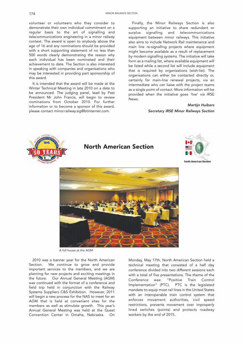
volunteer or volunteers who they consider todemonstrate their own individual commitment on aregular basis to the art of signalling andtelecommunications engineering in a minor railwaycontext. The award is open to anybody above theage of 16 and any nominations should be providedwith a short supporting statement of no less than500 words clearly demonstrating the reason whyeach individual has been nominated and theirachievement to date. The Section is also interestedin speaking with companies and organisations whomay be interested in providing part sponsorship ofthis award.
It is intended that the award will be made at theWinter Technical Meeting in late 2010 on a date tobe announced. The judging panel, lead by PastPresident Mr John Francis, will begin to reviewnominations from October 2010. For furtherinformation or to become a sponsor of this award,please contact [email protected].
Finally, the Minor Railways Section is alsosupporting an initiative to share redundant orsurplus signalling and telecommunicationsequipment between minor railways. This initiativealso aims to include Network Rail maintenance andmain line re-signalling projects where equipmentmight become available as a result of replacementby modern signalling systems. The initiative will takeform as a mailing list, where available equipment willbe listed while a second list will include equipmentthat is required by organisations (wish-list). Theorganisations can either be contacted directly or,certainly for main-line renewal projects, via anintermediate who can liaise with the project teamsas a single point of contact. More information will beprovided when the initiative goes ‘live’ via IRSENews.
Martijn Huibers
Secretary IRSE Minor Railways Section
174 MINOR RAILWAYS SECTION
North American Section
A full house at the AGM
2010 was a banner year for the North AmericanSection. We continue to grow and provideimportant services to the members, and we areplanning for new projects and exciting meetings inthe future. Our Annual General Meeting (AGM)was continued with the format of a conference andfield trip held in conjunction with the RailwaySystems Suppliers C&S Exhibition. However, 2011will begin a new process for the NAS to meet for anAGM that is held at convenient sites for themembers as well as stimulate growth. This year’sAnnual General Meeting was held at the QuestConvention Center in Omaha, Nebraska. On
Monday, May 17th, North American Section held atechnical meeting that consisted of a half dayconference divided into two different sessions eachwith a total of five presentations. The theme of theConference was: “Positive Train ControlImplementation” (PTC). PTC is the legislatedmandate to equip most rail lines in the United Stateswith an interoperable train control system thatenforces movement authorities, civil speedrestrictions, prevents movement over improperlylined switches (points) and protects roadwayworkers by the end of 2015.
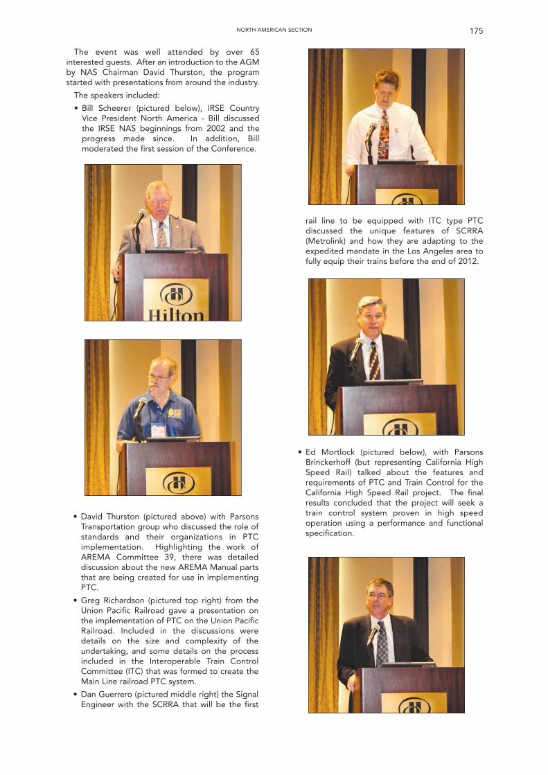
175NORTH AMERICAN SECTION
The event was well attended by over 65interested guests. After an introduction to the AGMby NAS Chairman David Thurston, the programstarted with presentations from around the industry.
The speakers included:
• Bill Scheerer (pictured below), IRSE CountryVice President North America - Bill discussedthe IRSE NAS beginnings from 2002 and theprogress made since. In addition, Billmoderated the first session of the Conference.
• David Thurston (pictured above) with ParsonsTransportation group who discussed the role ofstandards and their organizations in PTCimplementation. Highlighting the work ofAREMA Committee 39, there was detaileddiscussion about the new AREMA Manual partsthat are being created for use in implementingPTC.
• Greg Richardson (pictured top right) from theUnion Pacific Railroad gave a presentation onthe implementation of PTC on the Union PacificRailroad. Included in the discussions weredetails on the size and complexity of theundertaking, and some details on the processincluded in the Interoperable Train ControlCommittee (ITC) that was formed to create theMain Line railroad PTC system.
• Dan Guerrero (pictured middle right) the SignalEngineer with the SCRRA that will be the first
rail line to be equipped with ITC type PTCdiscussed the unique features of SCRRA(Metrolink) and how they are adapting to theexpedited mandate in the Los Angeles area tofully equip their trains before the end of 2012.
• Ed Mortlock (pictured below), with ParsonsBrinckerhoff (but representing California HighSpeed Rail) talked about the features andrequirements of PTC and Train Control for theCalifornia High Speed Rail project. The finalresults concluded that the project will seek atrain control system proven in high speedoperation using a performance and functionalspecification.
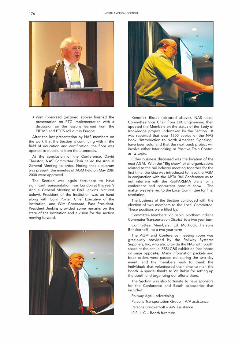
• Wim Coenraad (pictured above) finished thepresentation on PTC Implementation with adiscussion on the lessons learned from theERTMS and ETCS roll out in Europe.
After the last presentation by NAS members onthe work that the Section is continuing with in thefield of education and certification, the floor wasopened to questions from the attendees.
At the conclusion of the Conference, DavidThurston, NAS Committee Chair called the AnnualGeneral Meeting to order. Noting that a quorumwas present, the minutes of AGM held on May 20th2008 were approved.
The Section was again fortunate to havesignificant representation from London at this year’sAnnual General Meeting as Paul Jenkins (picturedbelow), President of the Institution was on handalong with Colin Porter, Chief Executive of theInstitution, and Wim Coenraad, Past President.President Jenkins provided some remarks on thestate of the Institution and a vision for the sectionmoving forward.
Kendrick Bisset (pictured above), NAS LocalCommittee Vice Chair from LTK Engineering thenupdated the Members on the status of the Body ofKnowledge project undertaken by the Section. Itwas reported that over 1300 copies of the NASbook “Introduction to North American Signaling”have been sold, and that the next book project willinvolve either Interlocking or Positive Train Controlas its topic.
Other business discussed was the location of thenext AGM. With the “Big show” of all organizationsrelated to the rail industry meeting together for thefirst time, the idea was introduced to have the AGMin conjunction with the APTA Rail Conference as tonot interfere with the RSSI/AREMA plans for aconference and concurrent product show. Thematter was referred to the Local Committee for finalresolution.
The business of the Section concluded with theelection of two members to the Local Committee.These positions were filled by:
Committee Members: Vic Babin, Northern IndianaCommuter Transportation District- to a two year term
Committee Members: Ed Mortlock, ParsonsBrinckerhoff - to a two year term
The AGM and Conference meeting room wasgraciously provided by the Railway SystemsSuppliers, Inc, who also provide the NAS with boothspace at the annual RSSI C&S exhibition (see photoon page opposite). Many information packets andbook orders were passed out during the two dayevent, and the members wish to thank theindividuals that volunteered their time to man thebooth. A special thanks to Vic Babin for setting upthe booth and organizing our efforts there.
The Section was also fortunate to have sponsorsfor the Conference and Booth accessories thatincluded:
Railway Age – advertising
Parsons Transportation Group – A/V assistance
Parsons Brinckerhoff – A/V assistance
ISIS, LLC – Booth furniture
176 NORTH AMERICAN SECTION
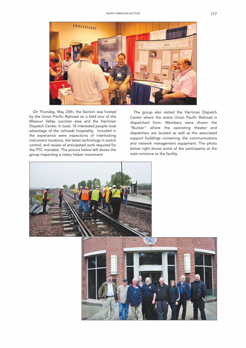
177NORTH AMERICAN SECTION
On Thursday, May 20th, the Section was hostedby the Union Pacific Railroad on a field tour of theMissouri Valley Junction area and the HarrimanDispatch Center. In total, 18 interested people tookadvantage of the railroads hospitality. Included inthe experience were inspections of interlockinginstrument locations, the latest technology in switchcontrol, and review of anticipated work required forthe PTC mandate. The picture below left shows thegroup inspecting a rotary helper movement.
The group also visited the Harriman DispatchCenter where the entire Union Pacific Railroad isdispatched from. Members were shown the“Bunker” where the operating theater anddispatchers are located as well as the associatedsupport buildings containing the communicationsand network management equipment. The photobelow right shows some of the participants at themain entrance to the facility.
178 NORTH AMERICAN SECTION
Following a number of years where the sectionsactivities had been substantially limited as a result oflocal employment circumstances, and in additionbeing a period that included the sad loss of IRSEPresident and colleague Alan Fisher, the section isable to report a brighter situation for the 2009-2010session. The programme of events planned by thelocal committee was largely completed, with theonly casualty being one of three technical papersthat had been programmed.
The first technical meeting was held on 14thOctober 2009 when Andy Millar and MatthewRadmore of Bombardier Transportation presentedtheir paper entitled “Assured Safety by theApplication of EBITrack 400 Coded Track Circuit”.The main thrust of the paper was the fact that thesafety performance of the track circuit for systemsassurance purposes is substantially mathematicallyproven, as against previous generations of trackcircuits where safety was proved in the main by wayof experimentation and trial application. It alsobecame evident to the audience that the wordcoded in the title does not carry the meaning as inprevious generations of track circuits, where the“coded” refers to the transmission of data via therails, but that the safety of the track circuit isachieved by way of coded digital communicationbetween transmitter and receiver. Nevertheless datatransmission remains an option within the design.The track circuit was designed in conjunction withthe University of Plymouth, in particular a groupwithin the university that specialises in digitaltransmissions relating mainly to satellitecommunications. When the two sides first cametogether, those from the railway signallingbackground began to wonder whether there wouldbe any useful outcome from the alliance withseemingly so little understanding of railwaysignalling and in particular track circuit safety needsby the students and graduates, but after some
detailed work during which both sides began tounderstand the others perspective andrequirements, there was a successful conclusion.Essentially the safety level meets the requiredfigures as a result of the extremely low probabilitythat a correct code will be received from a sourceother than the transmitter associated with aparticular receiver. Otherwise the track circuitcomponents are much as the well established TI21,e.g. tuning units, modulated audio frequency etc.The presenters wished it to be made known that akey member of the design team mathematician MissJ Cai would normally have been present, but hadreturned to China for a holiday.
The second technical meeting was held on 24thNovember 2009 when Richard Belli of TRE Ltd.presented his paper entitled “Chasing your Tail, orRegulating a Circular Railway”. This paper describedthe current Glasgow Subway Signal Control Systemand related in main to the headway regulationfunction of the computer based package, but alsoencompassed passenger information and otherfacilities included in the system. Richard was a keymember of the Bombardier team that designed andinstalled the control system and continued to beheavily involved in ironing out ongoing issues. Thebasic signal control elements of the installation weretouched upon, e.g. control and indication ofsignalling and traction, displays, automation versusmanual for various functions, but the main interestfor the evening was the train regulationmanagement designed to deal with a large numberof scenarios as encountered on the subway, whichby default included the timetable generation andediting facility. The software includes a functionwherein during traffic hours calculations are carriedout at very frequent intervals in turn initiating realtime changes to the non fixed parameters includedin the timetabled pattern. Given time the softwarewould arrive at the most efficient departure pattern
Plymouth Section
Preparations for the 2011 AGM are just gettingunderway. Any members interested in presenting apaper should contact Kendrick Bisset([email protected]) or Dave Thurston([email protected]) to find out moreabout this exciting opportunity. Details on the timeand location will be sent out when available.
The North American Section (NAS) was formed onMay 24, 2002 to support the goals of the Institutionin North America. The NAS presently has over 50members, and is encouraging railroadcommunication and signal professionals to join.While prospective NAS members must also bemembers of the IRSE, the NAS Local Committeewould be pleased to offer assistance to anyoneinterested in the applying for the benefits ofmembership with their application. NASmembership at present is free. IRSE membership isavailable at several levels, from Associate to Fellowwith appropriate membership fees. Information on
IRSE and NAS membership can be found atwww.irse.org.
North American Section officers are:
David Thurston, P.E., FIRSE, ChairmanVice President and Deputy Sector Manager -SystemsParsons Transportation Group1601 Market Street, 9th FloorPhiladelphia, PA 19103Tel: (215) 606-2365; Fax: (215) 567 1581E-mail: [email protected]
Kendrick Bisset, FIRSE, Vice ChairmanSenior Systems EngineerLTK EngineeringP.O. box 212Mountainhome, PA 18342Tel: 502 558 1062E-mail: [email protected]
179PLYMOUTH SECTION
for each of the 15 stations so as to provide a regularservice for customers at times of disruption. Thereare options for the operators to choose eithertimetable or headway mode, as best befits thesituation. The reason for the inclusion of “chasingyour tail” in the title is to emphasise the risk thattaking the easy option of holding trains at particularstations for regulation purposes on a circular railwayruns the risk they will all end up bunched together.There are so many scenarios that may affect therailway that the presentation was limited to anumber of obvious ones such as failed trains,temporary speed restrictions and special timetables.Richard was able to use technology to show largescreen displays of the train graph, network basedmanagement facilities and real time passengerinformation data.
Unfortunately the third of the three plannedlectures did not go ahead as the developmentstatus of the proposed subject matter was notsufficiently advanced. An attempt was made toidentify a replacement at short notice but this wasnot successful.
Following the suggestion at the previous AnnualGeneral Meeting that the section attempts to returnto holding a technical visit in conjunction with theAGM, this was achieved for this session with a visitto the Tamar Bridge control room and toll booths.The toll collection system for the road carryingsuspension bridge over the River Tamar had recentlybeen modified to include automatic toll collectionby the application of RFID tags. Attendees were notsurprised by much of what was shown in terms ofCCTV, the RFID process, lane control illuminationsetc., but were very impressed with a vehicle profilingsoftware package that was able to very accuratelyidentify any vehicle that passed though any of thebooths, using data from sensors positioned at each
of the booths. This was necessary in view of thenumber of different tolls that can apply, for exampletaking onto account number of axles, size of vehicle,distinction between buses and lorries, trailers etc. Itwould seem its cost will be recouped as a result ofthe number of vehicles that will not get away withpaying less than they should. As is often the casewith these events, the visit was extremely interestingand showed there was more to the system than maybe imagined.
Following the visit to the road bridge membersretreated to the Royal Albert pub under the railbridge of the same name for the Annual GeneralMeeting. At the meeting the committee for the2010-2011 session was elected as follows. AndyLovett and Andrew Jones stood down havingcompleted their three year stint, Dave Smith andRichard Nettleton (two years in office), and JulianStiles and Peter Stiles (one year in office) continuedas members of the committee. New members votedon to the committee were Dave Biss and JeremyWhitley. The meeting was keen to ensure that as faras possible the committee included representativesfrom as many of the local signalling companies ascould be entertained. Other essential businessdetermined that it should be ensured the committeemet and carried out its responsibilities, that thecurrent pattern of three technical papers plus onetechnical visit in conjunction with the AGM seemedto be an acceptable combination, and the financialstatus and banking arrangements were discussedand approved. The secretary Dave Came presentedhis report for the year and Alan Peters as financialscrutineer, although absent from the meeting, hadpreviously agreed the financial status.
At a subsequent committee meeting Dave Smithwas confirmed as Chairperson, and Julian Stiles waselected to the position of Vice-Chair.
Scottish SectionThe 2009/10 session started a month earlier than
in previous years with a lecture in September on the‘Efficient Modular Re-signalling of SecondaryRoutes’ by Pat McFadden of Network Rail. Thispresentation gave a detailed explanation of whatclassifies a secondary route, the new styleequipment that we can expect to see on it, and thechallenges faced in implementing modularsignalling onto an operation railway.
(Attendance : Members 25, Guests 3)
In October the section held a joint lecture with thePermanent Way Institute (PWI), the Institute ofRailway Operators (IRO), and the Institute ofMechanical Engineers (IMechE) on the ‘Edinburghto Glasgow Improvement Programme’ in the IET’sTeachers Building. This lecture was introduced andhosted by Bill Reeve (Transport Scotland), and hadpresentations on EGIP Engineering by Geoff Cook(Network Rail) and Roger Querns (TransportScotland). There was then a presentation on therolling stock by Jerry Farquharson (First ScotRail),
before being concluded by Ron McAulay (NetworkRail). For the first time, the joint lecture filled theIET’s lecture theatre with a number of non-membershaving to be turned away.
(Attendance (IRSE Only): Members 25, Guests 36)
In November we were once again pleased towelcome members of the institution and guestsfrom all parts of the British Isles to our AnnualDinner. The evening was started with a presentationon ‘Edinburgh Trams – Construction, Signalling andTraffic Interface’ by Steven Bell (Edinburgh Trams).The evening then moved on to the Dinner itself withthe keynote address being given by StewartStevenson (Scottish Government Minister forTransport). It is usually the tradition of the section toinvite the immediate past president to the dinner.Sadly, with the untimely passing of Alan Fisher inFebruary 2009, we were unable to continue with thistradition. However, Martin Govas (IRSE Treasurer)kindly accepted our invitation as a form of thanksfrom the section for all his help over the years. In
addition to Martin, Alan King and Tommy Gallacheralso accepted invitations to the dinner for theirmany years of work on the IRSE committee. Thaleswas this year’s kind sponsor for the lecture anddinner, this allowed us to subsidise the costs forfood and drink for the members tables. The dinnerwas once again excellent and the Marriot Hotel didus proud. This provided the guests with a relaxedatmosphere in which to catch up and informallydiscuss the issues of the day.
(Attendance (presentation): Members 32, Guests 12)
(Attendance (dinner): Members and Guests 193,Companies 14)
Following hotly in the heels of the annual dinner,the Scottish Section hosted the IRSE TechnicalSeminar on Friday the 20th and Saturday the 21st ofNovember. The seminar was titled “Scotland’sRailways” and focused on the new projectscommissioned, or in the process of beingcommissioned, on the Scottish Network. The Fridaystarted off at the Thales facility in Govan where theIRSE President Frans Heijnen gave an introductionand welcome to the group. A background tosignalling in Scotland was given by Alan King(Network Rail), before going to Dougie Kirk(Transport Scotland) who gave his experience onrecently commissioned Stirling – Alloa – Kincardinerail line. Graham Kelly (Invensys Rail) finished off thelecture part of the day with a presentation on theAirdrie to Bathgate rail line. The afternoon wasfinished off with a visit to the West of ScotlandSignalling Centre, with a presentation by Alan Taylor(Network Rail). Saturday’s events started off with atour of the SPT depot and presentation by PaulSmith (SPT) of the ‘Airwave’ emergency servicestelecommunication system currently beingcommissioned on the underground. The delegatesthen travelled to the Network Rail Training Centre atLarbert before being given a tour of the facility anda presentation on the GSM-R radio network byNetwork Rail and Cisco Systems. The two dayseminar was open to all IRSE members andattracted 33 members from both the UK andoverseas. The seminar was only able to beundertaken with the generous sponsorship fromParsons Brinckerhoff, Halcrow, Invensys, ScottWilson and Thales. I would personally like to thankall the members and presenters who helped overthe two days in making the seminar such a greatsuccess.
(Attendance: Members 33)
In January the section was due to host a lecture on‘A tale of two branch lines, home and away’, byDavid Nye (Scott Wilson). Unfortunately, due to theextreme weather conditions across the UK at thattime, the committee took the decision to cancel thislecture.
The February lecture is traditionally theTelecomms Lecture and this year was no different.Alan Blackwood (Babcock Rail) and Dr Paul Clark(Comms Design Ltd) gave a joint presentation on‘Application of Modern Digital Techniques for RETBRadio Equipment’. Mr Blackwood started off this
lecture with a concise background to RETBsignalling, and the existing analogue systemcurrently in use. Dr Clark then went on to detail thedifferences between analogue and digitaltelecommunications before showing the benefits interms of communication clarity and in using off theshelf technology. The lecture was very well attendedby both Signalling and TelecommunicationsEngineers.
(Attendance: Members 18, Guests 14)
In March the section organised a technical visit toNetwork Rail’s West of Scotland Signalling Centre(WSSC). As the section had recently hosted a visit tothe WSSC as part of the two day seminar inNovember, the evening was opened up to membersof the Retired Railway Officers Association (RROA).The evening was started in the MaintenanceDelivery Unit with a presentation by Alan Taylor(Network Rail) on why the new signalling centre wasrequired, the construction work, and the areas nowunder control from the operating floor. The groupthen split into three teams for tours of the operatingfloor by Luke Betteridge (Network Rail), theequipment room by Peter Allan (Invensys Rail) andthe signalling simulator by Alan Taylor (NetworkRail).
(Attendance: Members 14, Guests 20)
Our session ended in April with the joint AGM andQuiz Night. This was held locally in licensedpremises (O’Neills in Candleriggs) with a buffetsupplied from the remaining section funds.
Scottish Section Committee 2009 / 10:
Chairman: Lynsey Hunter
Vice Chairman: Craig Hourston
Secretary: Stephen Wright
Treasurer: Brian McKendrick
Peter RowellSimon Lowe
Paul SmithRicky Scarff
Chris WatersRobert GunnBarry Young
Chairman’s Report – Session 2009/2010Craig Hourston and myself have shared the duties
of the role of Chairman of the Scottish SectionCommittee over this past session. I undertook therole until Christmas, thereafter Craig took over themantle. It has been a pleasure to lead such adedicated committee, some of whom have servedfaithfully year after year. We have also beenfortunate to have a number of new members joiningthe committee. They have brought new ideas andenthusiasm to the committee and we hope that thiswill continue into the forthcoming session. We arealways delighted to accommodate anyoneinterested in becoming involved in the ScottishSection, so if you would like to help, just ask one ofthe committee members.
The committee has again worked tirelessly to puttogether an interesting programme of technical
180 SCOTTISH SECTION
meetings. This year 5 technical meetings have beenheld, the details of which have been summarised inthe Secretary’s report. We would like to thank ourspeakers for giving us of their time and expertise inorder to provide us with a stimulating programme.
Following previous successful events, anotherjoint meeting was held in October. This meeting, inthe IET Teachers Building was held jointly with theInstitute of Mechanical Engineers (IMechE),Permanent Way Institute (PWI) and Institution ofRailway Operators (IRO). The subject chosen wasthe much anticipated EGIP (Edinburgh to GlasgowImprovement Programme) and speakers from thethree main client bodies gave a cross-disciplineoverview. The meeting was very well attended, withstanding room only! We look forward to furtherjoint meetings in the future and continuing tostrengthen our relationships with other institutions.
With this collaboration in mind, I met with thechairmen of the other institutions at the IMechEannual dinner. They are all keen that we worktogether and attempt to open up our events tomembers of the various institutions. Our aims willbe to share programme information early so as toavoid duplication, and also to publicise each others’events. Hopefully this may increase our attendance,and also encourage our members to visit otherinstitution events that may interest them.
The Annual Dinner remains as successful as ever.Despite the gloomy financial climate of the pastyear, attendance was high, with the majority ofcompanies being represented. Thales was themajor sponsor this year, with other companiessupporting through their attendance. Thepopularity of the largest rail dinner in Scotlandcontinues to attract members and guests from allover the British Isles and beyond! This year it was apleasure to have Martin Govas, the IRSE Treasurer,as a guest. We were also privileged to have StewartStevenson, the Scottish Minister for Transport as ourafter dinner speaker. Since the Dinner has noweffectively evolved into being the main ‘RailwayIndustry’ specific annual function in Scotland it hasbeen suggested that it may now be an appropriatetime to recognise this and rebrand the event as theScottish Railway Forum Annual Dinner. By doing thisit would be possible to share the organisation of theevent with the other organisations. This issomething that may be looked at over theforthcoming year for consideration by our members.
The Scottish Section was in a privileged positionthis year as it was asked to host the annual IRSEtechnical visit. This event took a significant effort toorganise, but the committee stepped up to thechallenge. Focussing on ‘Scotland’s Railways’ thevisit included lectures on SAK (Stirling AlloaKincardine) and A2B (Airdrie to Bathgate). Site visitsincluded the Glasgow Underground, West ofScotland Signal Centre and Larbert Training School.Organising this event was a very significant step forthe committee. From the feedback received we
believe we did an excellent job, however we wouldhave liked to have seen some more support fromour Scottish members. I know that the visits mayhave been to sites that you have all seen before, butthese events are designed to promote cross industrycommunication and the social aspect is key. I wouldencourage you all to attend these seminars if youcan in the future.
As stated in the Secretary’s report unfortunatelywe had to cancel the January lecture due touncertainty in the travel arrangements of ourspeaker caused by the severe weather we had atthat time. Hopefully this winter was not a taste ofthings to come, if so we shall need to plan to invitelocal speakers during the winter months!
February has become the month of the telecomlecture on our calendar and this year’s presentationwas notable for its ambitious choice of including alive demonstration of the new RETB digitaltechnology. It is always a risky thing to attempt toinclude demonstrations of equipment andtechnology in a lecture but in this case everythingworked perfectly with a live radio call put inbetween the Caledonian University lecture theatreand the signaller at Banavie. This capped off anexcellent technical lecture nicely demonstrating thetheory in practice.
The final event, other than the AGM, arrangedduring this year’s events calendar was [another]technical visit to the, now not so new, West ofScotland Signalling Centre. It was good to be ableto open this visit up to our friends and ex colleaguesin the Retired Railway Operators Association andthis helped to keep the numbers up to make theevent worthwhile.
We have very much appreciated the support fromthe committee members who managed to find thetime to attend meetings and undertake all thevaried tasks that need to be done. The running ofthe section does take a lot of time and effort and isentirely reliant on this voluntary support. Specialmention must be given to those involved with thetechnical visit and the additional workload that itbrought. Many thanks to everyone who has beeninvolved, however small or large a part you played.
A special mention must also go to Stephen Wrightin his role as Secretary. Steve really holds thecommittee together and does the large majority ofthe work. We really appreciate his commitment andhope that he wants to continue with hisinvolvement!
As always the Section relies on the support of themembership; we would like to record our thanks toall. I would like to ask you to encourage yourcolleagues to attend our meetings, so we cancontinue to build on the success already achieved.
Lynsey Hunter and Craig HourstonChairmen, IRSE Scottish Section 2009/2010
22nd April 2010
181SCOTTISH SECTION
182
The IRSE Singaporean Section has had anotherquiet year in comparison to previous years, mainlydue to the increased effort required by the ongoingprojects in Singapore. However, the local sectioncontinued to provide good opportunities fornetworking, even though there were no TechnicalPresentations this year.
As contracts finish and new ones begin there areinevitable staff movements in and out of Singapore,happily the section has managed to attract newmembers locally to maintain membership levels.
We were happy to welcome the IRSE PresidentFrans Heijnen for a short visit. During his stay hemanaged to take in some of the local installations,including the Circle Line Depot.
We are always happy to hear from any IRSEmembers, who are visiting or passing throughSingapore, particularly those who would beinterested in presenting a paper.
SECTION WEB SITE The local section web site gives details of all thesections activities and forthcoming presentations. Italso includes articles of interest and useful links.The IRSE (Singaporean Section) web-site address iswww.irse.org.sg, please pay us a visit.
COMMITTEEChairman Mark Appleyard
Vice-Chairman Russell Shield
Secretary Lim Meng Chai
Treasurer Ian Tomlins
Committee Members Toh Kim ToonLim Chiau Khoon
Lor Kok YewMartin White
Ian TomlinsSecretary IRSE Singaporean Section
Singaporean Section
Southern African Section
MEMBERSHIPThanks in the main to the efforts of Mr Ken Boss,
a substantial batch of new membership applicationswere received and processed in the early part of2009. Further applications were received andprocessed in much smaller numbers throughout thebalance of 2009. As a result of this, the activemembership of the Southern African Section grewfrom 55 to 103 by the end of the 2009/10 session.This achievement was heartily applauded by theserving chairman and committee.
In the context of the significant change in themembership numbers, a comprehensive review andreconciliation of the membership records was done.As per the amended records on hand, themembership at the end of the session was made upas follows:
Honorary Fellows 3
Fellows 5
Members 42
Associate Members 38
Associates 13
Companions 2
The membership per country within the SouthernAfrican Section was:
South Africa 101
Botswana 1
Zimbabwe 1
The application to the Engineering Council ofSouth Africa (ECSA) for recognition as a VoluntaryAssociation, as referred to in the proceedings forthe 2007/08, was declined on the basis of themembership of the Southern African Section of the
IRSE being too small. Their criterion is amembership of 100. The membership numbers nowbeing fractionally in excess of the ECSA criteriaopens the door for the Southern African Section ofthe IRSE to resubmit an application.
OFFICE BEARERS FOR THE 2009SESSION
In accordance with the Constitution of TheInstitution of Railway Signal Engineers and the Bye-Laws of the Southern African Section, the term ofoffice for four General Committee members expiredat the end of the 2008 session.
The General Committee members affected were:-
Mr R C Gould
Mr B J van der Merwe
Mrs A Govender
Mr J C Van de Pol
Having relocated to Durban and having gotmarried during 2008, compounded by workpressures and the logistic challenges ofparticipating in the regular Johannesburg basedmeetings and events, Mrs A Govender declinednomination for re-election.
Only four nominations were received for whichthe nominees had formally indicated theirwillingness to stand for election/ re-election. Thesenominees were:-
Mr R C Gould
Mr B J van der Merwe
Mr J C Van de Pol
Mr B M Ostendorf
At the 2008 Annual General Meeting that washeld on 04 November 2008, all four of these
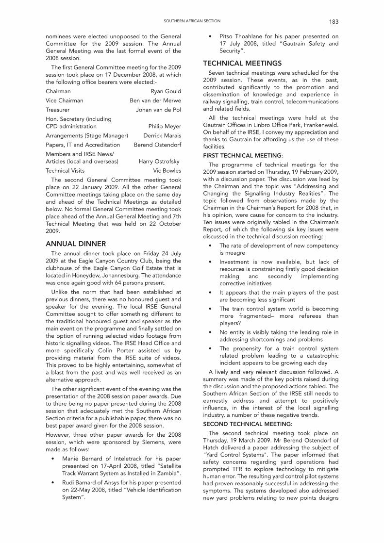
183SOUTHERN AFRICAN SECTION
nominees were elected unopposed to the GeneralCommittee for the 2009 session. The AnnualGeneral Meeting was the last formal event of the2008 session.
The first General Committee meeting for the 2009session took place on 17 December 2008, at whichthe following office bearers were elected:-
Chairman Ryan Gould
Vice Chairman Ben van der Merwe
Treasurer Johan van de Pol
Hon. Secretary (including CPD administration Philip Meyer
Arrangements (Stage Manager) Derrick Marais
Papers, IT and Accreditation Berend Ostendorf
Members and IRSE News/Articles (local and overseas) Harry Ostrofsky
Technical Visits Vic Bowles
The second General Committee meeting tookplace on 22 January 2009. All the other GeneralCommittee meetings taking place on the same dayand ahead of the Technical Meetings as detailedbelow. No formal General Committee meeting tookplace ahead of the Annual General Meeting and 7thTechnical Meeting that was held on 22 October2009.
ANNUAL DINNERThe annual dinner took place on Friday 24 July
2009 at the Eagle Canyon Country Club, being theclubhouse of the Eagle Canyon Golf Estate that islocated in Honeydew, Johannesburg. The attendancewas once again good with 64 persons present.
Unlike the norm that had been established atprevious dinners, there was no honoured guest andspeaker for the evening. The local IRSE GeneralCommittee sought to offer something different tothe traditional honoured guest and speaker as themain event on the programme and finally settled onthe option of running selected video footage fromhistoric signalling videos. The IRSE Head Office andmore specifically Colin Porter assisted us byproviding material from the IRSE suite of videos.This proved to be highly entertaining, somewhat ofa blast from the past and was well received as analternative approach.
The other significant event of the evening was thepresentation of the 2008 session paper awards. Dueto there being no paper presented during the 2008session that adequately met the Southern AfricanSection criteria for a publishable paper, there was nobest paper award given for the 2008 session.
However, three other paper awards for the 2008session, which were sponsored by Siemens, weremade as follows:
• Manie Bernard of Inteletrack for his paperpresented on 17-April 2008, titled “SatelliteTrack Warrant System as Installed in Zambia”.
• Rudi Barnard of Ansys for his paper presentedon 22-May 2008, titled “Vehicle IdentificationSystem”.
• Pitso Thoahlane for his paper presented on17 July 2008, titled “Gautrain Safety andSecurity”.
TECHNICAL MEETINGSSeven technical meetings were scheduled for the
2009 session. These events, as in the past,contributed significantly to the promotion anddissemination of knowledge and experience inrailway signalling, train control, telecommunicationsand related fields.
All the technical meetings were held at theGautrain Offices in Linbro Office Park, Frankenwald.On behalf of the IRSE, I convey my appreciation andthanks to Gautrain for affording us the use of thesefacilities.
FIRST TECHNICAL MEETING:
The programme of technical meetings for the2009 session started on Thursday, 19 February 2009,with a discussion paper. The discussion was lead bythe Chairman and the topic was “Addressing andChanging the Signalling Industry Realities”. Thetopic followed from observations made by theChairman in the Chairman’s Report for 2008 that, inhis opinion, were cause for concern to the industry.Ten issues were originally tabled in the Chairman’sReport, of which the following six key issues werediscussed in the technical discussion meeting:
• The rate of development of new competencyis meagre
• Investment is now available, but lack ofresources is constraining firstly good decisionmaking and secondly implementingcorrective initiatives
• It appears that the main players of the pastare becoming less significant
• The train control system world is becomingmore fragmented– more referees thanplayers?
• No entity is visibly taking the leading role inaddressing shortcomings and problems
• The propensity for a train control systemrelated problem leading to a catastrophicincident appears to be growing each day
A lively and very relevant discussion followed. Asummary was made of the key points raised duringthe discussion and the proposed actions tabled. TheSouthern African Section of the IRSE still needs toearnestly address and attempt to positivelyinfluence, in the interest of the local signallingindustry, a number of these negative trends.
SECOND TECHNICAL MEETING:
The second technical meeting took place onThursday, 19 March 2009. Mr Berend Ostendorf ofHatch delivered a paper addressing the subject of"Yard Control Systems". The paper informed thatsafety concerns regarding yard operations hadprompted TFR to explore technology to mitigatehuman error. The resulting yard control pilot systemshad proven reasonably successful in addressing thesymptoms. The systems developed also addressednew yard problems relating to new points designs
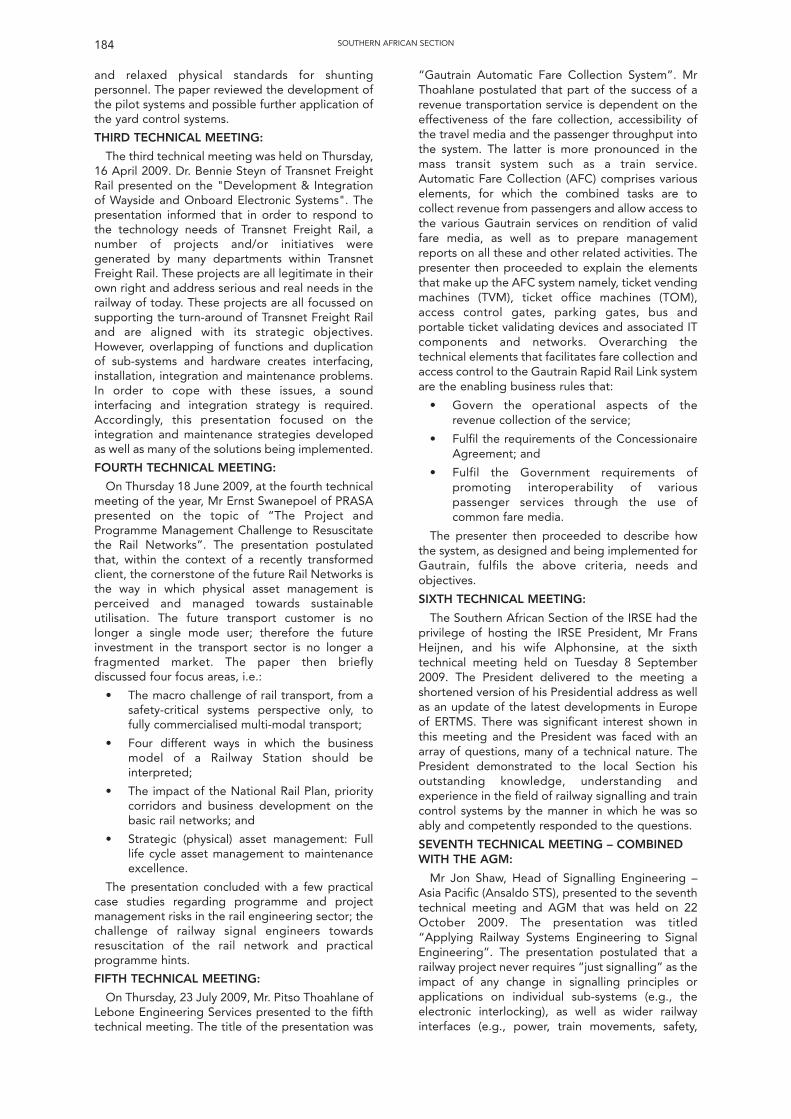
and relaxed physical standards for shuntingpersonnel. The paper reviewed the development ofthe pilot systems and possible further application ofthe yard control systems.
THIRD TECHNICAL MEETING:
The third technical meeting was held on Thursday,16 April 2009. Dr. Bennie Steyn of Transnet FreightRail presented on the "Development & Integrationof Wayside and Onboard Electronic Systems". Thepresentation informed that in order to respond tothe technology needs of Transnet Freight Rail, anumber of projects and/or initiatives weregenerated by many departments within TransnetFreight Rail. These projects are all legitimate in theirown right and address serious and real needs in therailway of today. These projects are all focussed onsupporting the turn-around of Transnet Freight Railand are aligned with its strategic objectives.However, overlapping of functions and duplicationof sub-systems and hardware creates interfacing,installation, integration and maintenance problems.In order to cope with these issues, a soundinterfacing and integration strategy is required.Accordingly, this presentation focused on theintegration and maintenance strategies developedas well as many of the solutions being implemented.
FOURTH TECHNICAL MEETING:
On Thursday 18 June 2009, at the fourth technicalmeeting of the year, Mr Ernst Swanepoel of PRASApresented on the topic of “The Project andProgramme Management Challenge to Resuscitatethe Rail Networks”. The presentation postulatedthat, within the context of a recently transformedclient, the cornerstone of the future Rail Networks isthe way in which physical asset management isperceived and managed towards sustainableutilisation. The future transport customer is nolonger a single mode user; therefore the futureinvestment in the transport sector is no longer afragmented market. The paper then brieflydiscussed four focus areas, i.e.:
• The macro challenge of rail transport, from asafety-critical systems perspective only, tofully commercialised multi-modal transport;
• Four different ways in which the businessmodel of a Railway Station should beinterpreted;
• The impact of the National Rail Plan, prioritycorridors and business development on thebasic rail networks; and
• Strategic (physical) asset management: Fulllife cycle asset management to maintenanceexcellence.
The presentation concluded with a few practicalcase studies regarding programme and projectmanagement risks in the rail engineering sector; thechallenge of railway signal engineers towardsresuscitation of the rail network and practicalprogramme hints.
FIFTH TECHNICAL MEETING:
On Thursday, 23 July 2009, Mr. Pitso Thoahlane ofLebone Engineering Services presented to the fifthtechnical meeting. The title of the presentation was
“Gautrain Automatic Fare Collection System”. MrThoahlane postulated that part of the success of arevenue transportation service is dependent on theeffectiveness of the fare collection, accessibility ofthe travel media and the passenger throughput intothe system. The latter is more pronounced in themass transit system such as a train service.Automatic Fare Collection (AFC) comprises variouselements, for which the combined tasks are tocollect revenue from passengers and allow access tothe various Gautrain services on rendition of validfare media, as well as to prepare managementreports on all these and other related activities. Thepresenter then proceeded to explain the elementsthat make up the AFC system namely, ticket vendingmachines (TVM), ticket office machines (TOM),access control gates, parking gates, bus andportable ticket validating devices and associated ITcomponents and networks. Overarching thetechnical elements that facilitates fare collection andaccess control to the Gautrain Rapid Rail Link systemare the enabling business rules that:
• Govern the operational aspects of therevenue collection of the service;
• Fulfil the requirements of the ConcessionaireAgreement; and
• Fulfil the Government requirements ofpromoting interoperability of variouspassenger services through the use ofcommon fare media.
The presenter then proceeded to describe howthe system, as designed and being implemented forGautrain, fulfils the above criteria, needs andobjectives.
SIXTH TECHNICAL MEETING:
The Southern African Section of the IRSE had theprivilege of hosting the IRSE President, Mr FransHeijnen, and his wife Alphonsine, at the sixthtechnical meeting held on Tuesday 8 September2009. The President delivered to the meeting ashortened version of his Presidential address as wellas an update of the latest developments in Europeof ERTMS. There was significant interest shown inthis meeting and the President was faced with anarray of questions, many of a technical nature. ThePresident demonstrated to the local Section hisoutstanding knowledge, understanding andexperience in the field of railway signalling and traincontrol systems by the manner in which he was soably and competently responded to the questions.
SEVENTH TECHNICAL MEETING – COMBINEDWITH THE AGM:
Mr Jon Shaw, Head of Signalling Engineering –Asia Pacific (Ansaldo STS), presented to the seventhtechnical meeting and AGM that was held on 22October 2009. The presentation was titled“Applying Railway Systems Engineering to SignalEngineering”. The presentation postulated that arailway project never requires “just signalling” as theimpact of any change in signalling principles orapplications on individual sub-systems (e.g., theelectronic interlocking), as well as wider railwayinterfaces (e.g., power, train movements, safety,
SOUTHERN AFRICAN SECTION184
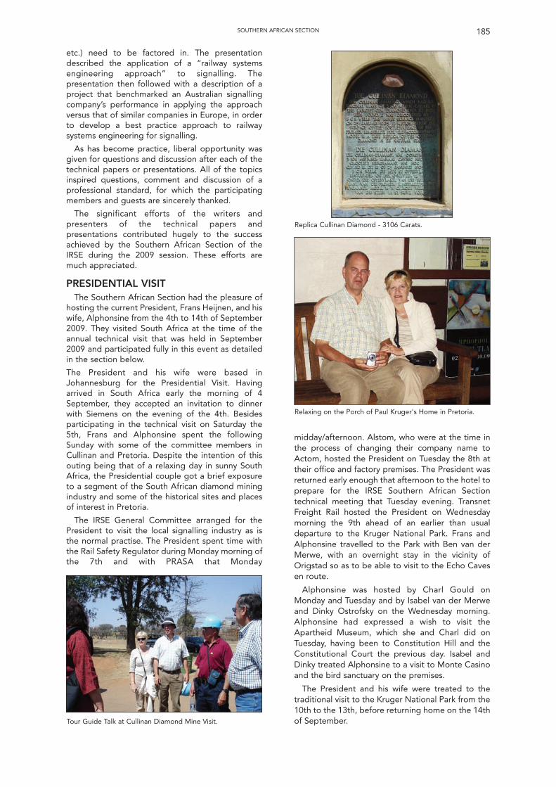
185SOUTHERN AFRICAN SECTION
etc.) need to be factored in. The presentationdescribed the application of a “railway systemsengineering approach” to signalling. Thepresentation then followed with a description of aproject that benchmarked an Australian signallingcompany’s performance in applying the approachversus that of similar companies in Europe, in orderto develop a best practice approach to railwaysystems engineering for signalling.
As has become practice, liberal opportunity wasgiven for questions and discussion after each of thetechnical papers or presentations. All of the topicsinspired questions, comment and discussion of aprofessional standard, for which the participatingmembers and guests are sincerely thanked.
The significant efforts of the writers andpresenters of the technical papers andpresentations contributed hugely to the successachieved by the Southern African Section of theIRSE during the 2009 session. These efforts aremuch appreciated.
PRESIDENTIAL VISITThe Southern African Section had the pleasure of
hosting the current President, Frans Heijnen, and hiswife, Alphonsine from the 4th to 14th of September2009. They visited South Africa at the time of theannual technical visit that was held in September2009 and participated fully in this event as detailedin the section below.
The President and his wife were based inJohannesburg for the Presidential Visit. Havingarrived in South Africa early the morning of 4September, they accepted an invitation to dinnerwith Siemens on the evening of the 4th. Besidesparticipating in the technical visit on Saturday the5th, Frans and Alphonsine spent the followingSunday with some of the committee members inCullinan and Pretoria. Despite the intention of thisouting being that of a relaxing day in sunny SouthAfrica, the Presidential couple got a brief exposureto a segment of the South African diamond miningindustry and some of the historical sites and placesof interest in Pretoria.
The IRSE General Committee arranged for thePresident to visit the local signalling industry as isthe normal practise. The President spent time withthe Rail Safety Regulator during Monday morning ofthe 7th and with PRASA that Monday
midday/afternoon. Alstom, who were at the time inthe process of changing their company name toActom, hosted the President on Tuesday the 8th attheir office and factory premises. The President wasreturned early enough that afternoon to the hotel toprepare for the IRSE Southern African Sectiontechnical meeting that Tuesday evening. TransnetFreight Rail hosted the President on Wednesdaymorning the 9th ahead of an earlier than usualdeparture to the Kruger National Park. Frans andAlphonsine travelled to the Park with Ben van derMerwe, with an overnight stay in the vicinity ofOrigstad so as to be able to visit to the Echo Cavesen route.
Alphonsine was hosted by Charl Gould onMonday and Tuesday and by Isabel van der Merweand Dinky Ostrofsky on the Wednesday morning.Alphonsine had expressed a wish to visit theApartheid Museum, which she and Charl did onTuesday, having been to Constitution Hill and theConstitutional Court the previous day. Isabel andDinky treated Alphonsine to a visit to Monte Casinoand the bird sanctuary on the premises.
The President and his wife were treated to thetraditional visit to the Kruger National Park from the10th to the 13th, before returning home on the 14thof September.
Replica Cullinan Diamond - 3106 Carats.
Relaxing on the Porch of Paul Kruger's Home in Pretoria.
Tour Guide Talk at Cullinan Diamond Mine Visit.
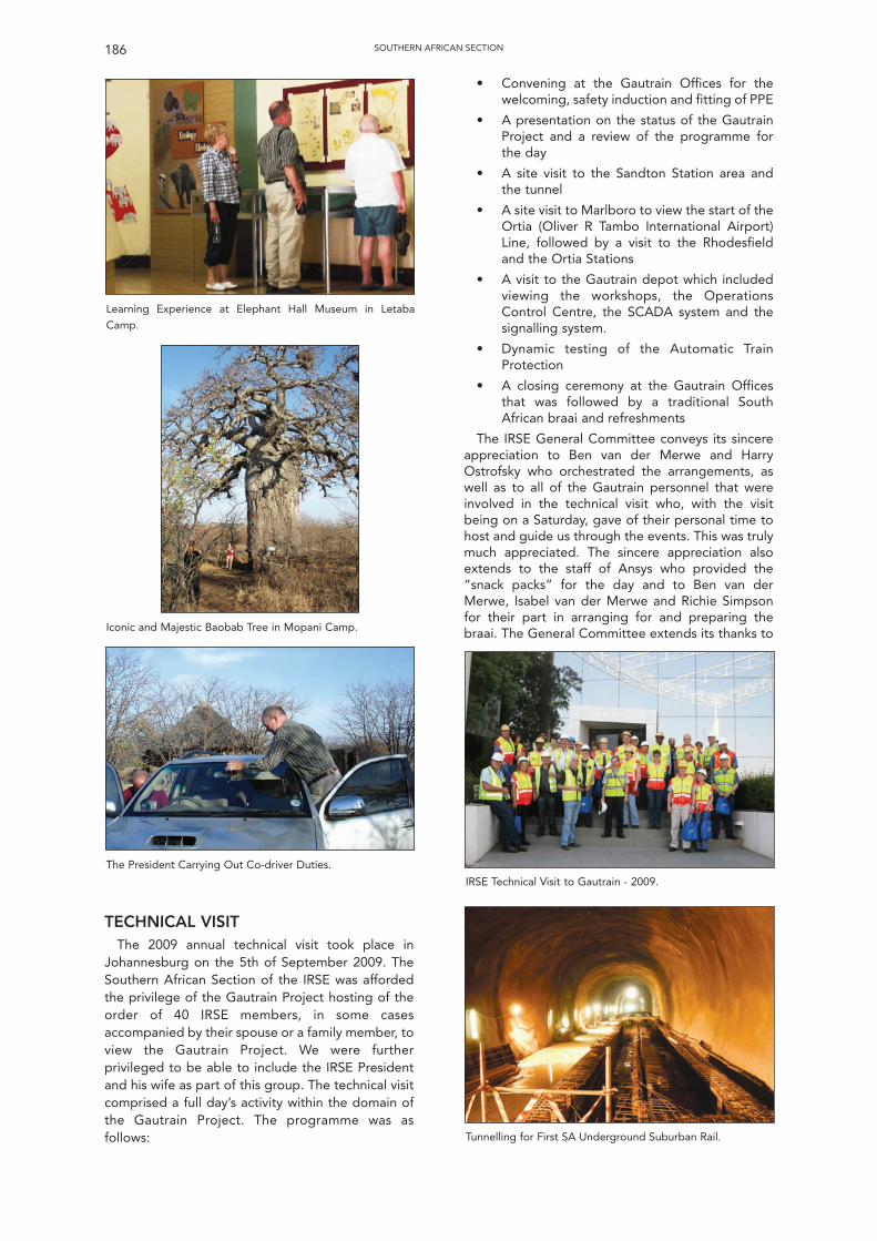
SOUTHERN AFRICAN SECTION186
• Convening at the Gautrain Offices for thewelcoming, safety induction and fitting of PPE
• A presentation on the status of the GautrainProject and a review of the programme forthe day
• A site visit to the Sandton Station area andthe tunnel
• A site visit to Marlboro to view the start of theOrtia (Oliver R Tambo International Airport)Line, followed by a visit to the Rhodesfieldand the Ortia Stations
• A visit to the Gautrain depot which includedviewing the workshops, the OperationsControl Centre, the SCADA system and thesignalling system.
• Dynamic testing of the Automatic TrainProtection
• A closing ceremony at the Gautrain Officesthat was followed by a traditional SouthAfrican braai and refreshments
The IRSE General Committee conveys its sincereappreciation to Ben van der Merwe and HarryOstrofsky who orchestrated the arrangements, aswell as to all of the Gautrain personnel that wereinvolved in the technical visit who, with the visitbeing on a Saturday, gave of their personal time tohost and guide us through the events. This was trulymuch appreciated. The sincere appreciation alsoextends to the staff of Ansys who provided the“snack packs” for the day and to Ben van derMerwe, Isabel van der Merwe and Richie Simpsonfor their part in arranging for and preparing thebraai. The General Committee extends its thanks to
TECHNICAL VISITThe 2009 annual technical visit took place in
Johannesburg on the 5th of September 2009. TheSouthern African Section of the IRSE was affordedthe privilege of the Gautrain Project hosting of theorder of 40 IRSE members, in some casesaccompanied by their spouse or a family member, toview the Gautrain Project. We were furtherprivileged to be able to include the IRSE Presidentand his wife as part of this group. The technical visitcomprised a full day’s activity within the domain ofthe Gautrain Project. The programme was asfollows:
Learning Experience at Elephant Hall Museum in Letaba
Camp.
IRSE Technical Visit to Gautrain - 2009.
Tunnelling for First SA Underground Suburban Rail.
Iconic and Majestic Baobab Tree in Mopani Camp.
The President Carrying Out Co-driver Duties.
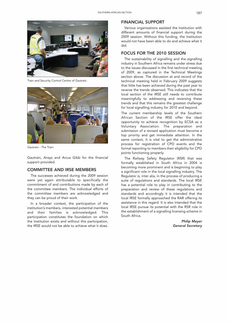
Gautrain, Ansys and Arcus Gibb for the financialsupport provided.
COMMITTEE AND IRSE MEMBERSThe successes achieved during the 2009 session
were yet again attributable to specifically thecommitment of and contributions made by each ofthe committee members. The individual efforts ofthe committee members are acknowledged andthey can be proud of their work.
In a broader context, the participation of theinstitution’s members, interested potential membersand their families is acknowledged. Thisparticipation constitutes the foundation on whichthe Institution exists and without this participation,the IRSE would not be able to achieve what it does.
FINANCIAL SUPPORTVarious organisations assisted the Institution with
different amounts of financial support during the2009 session. Without this funding, the Institutionwould not have been able to do and achieve what itdid.
FOCUS FOR THE 2010 SESSIONThe sustainability of signalling and the signalling
industry in Southern Africa remains under stress dueto the issues discussed in the first technical meetingof 2009, as captured in the Technical Meetingssection above. The discussion at and record of thetechnical meeting held in February 2009 suggeststhat little has been achieved during the past year toreverse the trends observed. This indicates that thelocal section of the IRSE still needs to contributemeaningfully to addressing and reversing thesetrends and that this remains the greatest challengefor local signalling industry for 2010 and beyond.
The current membership levels of the SouthernAfrican Section of the IRSE offer the idealopportunity to achieve recognition by ECSA as aVoluntary Association. The preparation andsubmission of a revised application must become atop priority and get immediate attention. In thesame context, it is vital to get the administrativeprocess for registration of CPD events and theformal reporting to members their eligibility for CPDpoints functioning properly.
The Railway Safety Regulator (RSR) that wasformally established in South Africa in 2004 isbecoming more prominent and is beginning to playa significant role in the local signalling industry. TheRegulator is, inter alia, in the process of producing asuite of regulations and standards. The local IRSEhas a potential role to play in contributing to thepreparation and review of these regulations andstandards and accordingly it is intended that thelocal IRSE formally approached the RAR offering itsassistance in this regard. It is also intended that thelocal IRSE pursue its potential with the RSR role inthe establishment of a signalling licensing scheme inSouth Africa.
Philip MeyerGeneral Secretary
187SOUTHERN AFRICAN SECTION
Train and Security Control Centre of Gautrain.
Gautrain - The Train.
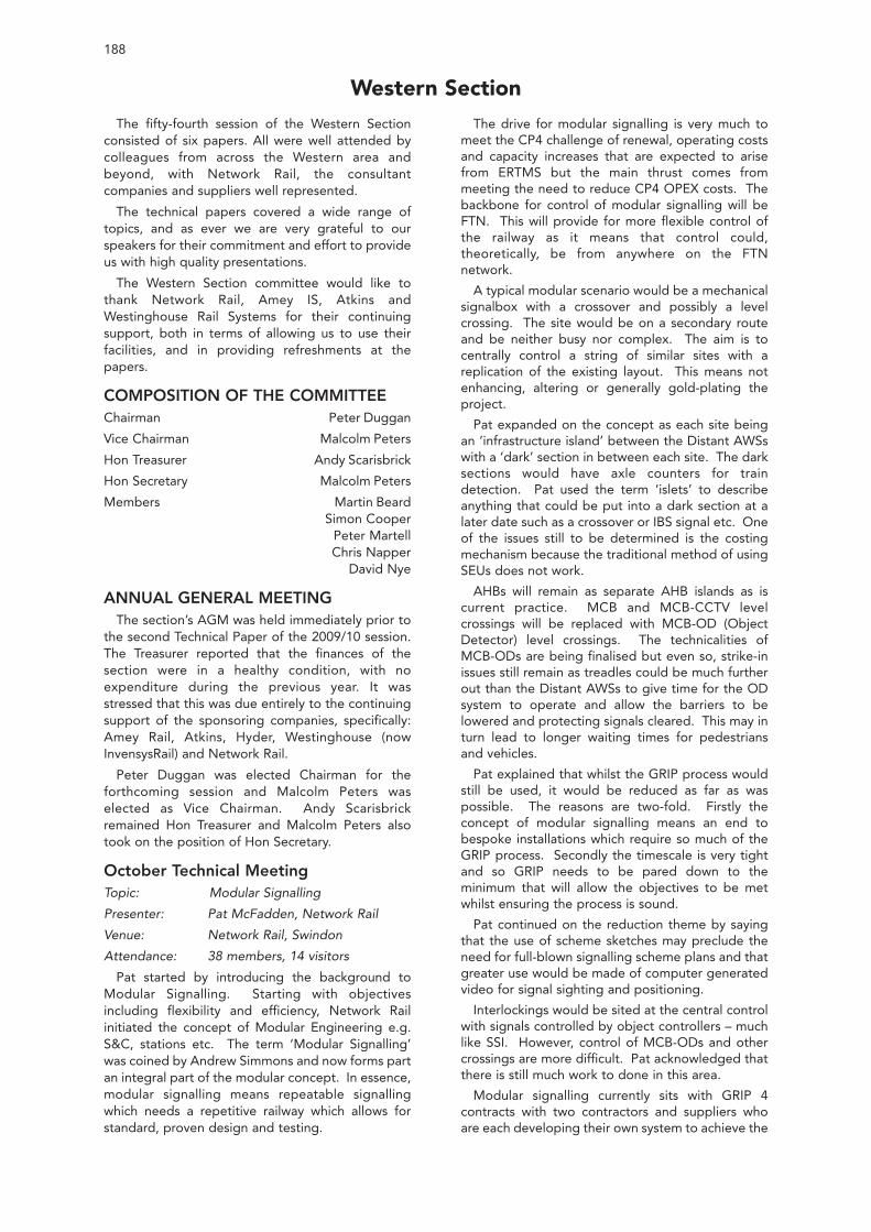
188
The fifty-fourth session of the Western Sectionconsisted of six papers. All were well attended bycolleagues from across the Western area andbeyond, with Network Rail, the consultantcompanies and suppliers well represented.
The technical papers covered a wide range oftopics, and as ever we are very grateful to ourspeakers for their commitment and effort to provideus with high quality presentations.
The Western Section committee would like tothank Network Rail, Amey IS, Atkins andWestinghouse Rail Systems for their continuingsupport, both in terms of allowing us to use theirfacilities, and in providing refreshments at thepapers.
COMPOSITION OF THE COMMITTEEChairman Peter Duggan
Vice Chairman Malcolm Peters
Hon Treasurer Andy Scarisbrick
Hon Secretary Malcolm Peters
Members Martin BeardSimon Cooper
Peter MartellChris Napper
David Nye
ANNUAL GENERAL MEETINGThe section’s AGM was held immediately prior to
the second Technical Paper of the 2009/10 session.The Treasurer reported that the finances of thesection were in a healthy condition, with noexpenditure during the previous year. It wasstressed that this was due entirely to the continuingsupport of the sponsoring companies, specifically:Amey Rail, Atkins, Hyder, Westinghouse (nowInvensysRail) and Network Rail.
Peter Duggan was elected Chairman for theforthcoming session and Malcolm Peters waselected as Vice Chairman. Andy Scarisbrickremained Hon Treasurer and Malcolm Peters alsotook on the position of Hon Secretary.
October Technical MeetingTopic: Modular Signalling
Presenter: Pat McFadden, Network Rail
Venue: Network Rail, Swindon
Attendance: 38 members, 14 visitors
Pat started by introducing the background toModular Signalling. Starting with objectivesincluding flexibility and efficiency, Network Railinitiated the concept of Modular Engineering e.g.S&C, stations etc. The term ‘Modular Signalling’was coined by Andrew Simmons and now forms partan integral part of the modular concept. In essence,modular signalling means repeatable signallingwhich needs a repetitive railway which allows forstandard, proven design and testing.
The drive for modular signalling is very much tomeet the CP4 challenge of renewal, operating costsand capacity increases that are expected to arisefrom ERTMS but the main thrust comes frommeeting the need to reduce CP4 OPEX costs. Thebackbone for control of modular signalling will beFTN. This will provide for more flexible control ofthe railway as it means that control could,theoretically, be from anywhere on the FTNnetwork.
A typical modular scenario would be a mechanicalsignalbox with a crossover and possibly a levelcrossing. The site would be on a secondary routeand be neither busy nor complex. The aim is tocentrally control a string of similar sites with areplication of the existing layout. This means notenhancing, altering or generally gold-plating theproject.
Pat expanded on the concept as each site beingan ‘infrastructure island’ between the Distant AWSswith a ‘dark’ section in between each site. The darksections would have axle counters for traindetection. Pat used the term ‘islets’ to describeanything that could be put into a dark section at alater date such as a crossover or IBS signal etc. Oneof the issues still to be determined is the costingmechanism because the traditional method of usingSEUs does not work.
AHBs will remain as separate AHB islands as iscurrent practice. MCB and MCB-CCTV levelcrossings will be replaced with MCB-OD (ObjectDetector) level crossings. The technicalities ofMCB-ODs are being finalised but even so, strike-inissues still remain as treadles could be much furtherout than the Distant AWSs to give time for the ODsystem to operate and allow the barriers to belowered and protecting signals cleared. This may inturn lead to longer waiting times for pedestriansand vehicles.
Pat explained that whilst the GRIP process wouldstill be used, it would be reduced as far as waspossible. The reasons are two-fold. Firstly theconcept of modular signalling means an end tobespoke installations which require so much of theGRIP process. Secondly the timescale is very tightand so GRIP needs to be pared down to theminimum that will allow the objectives to be metwhilst ensuring the process is sound.
Pat continued on the reduction theme by sayingthat the use of scheme sketches may preclude theneed for full-blown signalling scheme plans and thatgreater use would be made of computer generatedvideo for signal sighting and positioning.
Interlockings would be sited at the central controlwith signals controlled by object controllers – muchlike SSI. However, control of MCB-ODs and othercrossings are more difficult. Pat acknowledged thatthere is still much work to done in this area.
Modular signalling currently sits with GRIP 4contracts with two contractors and suppliers whoare each developing their own system to achieve the
Western Section
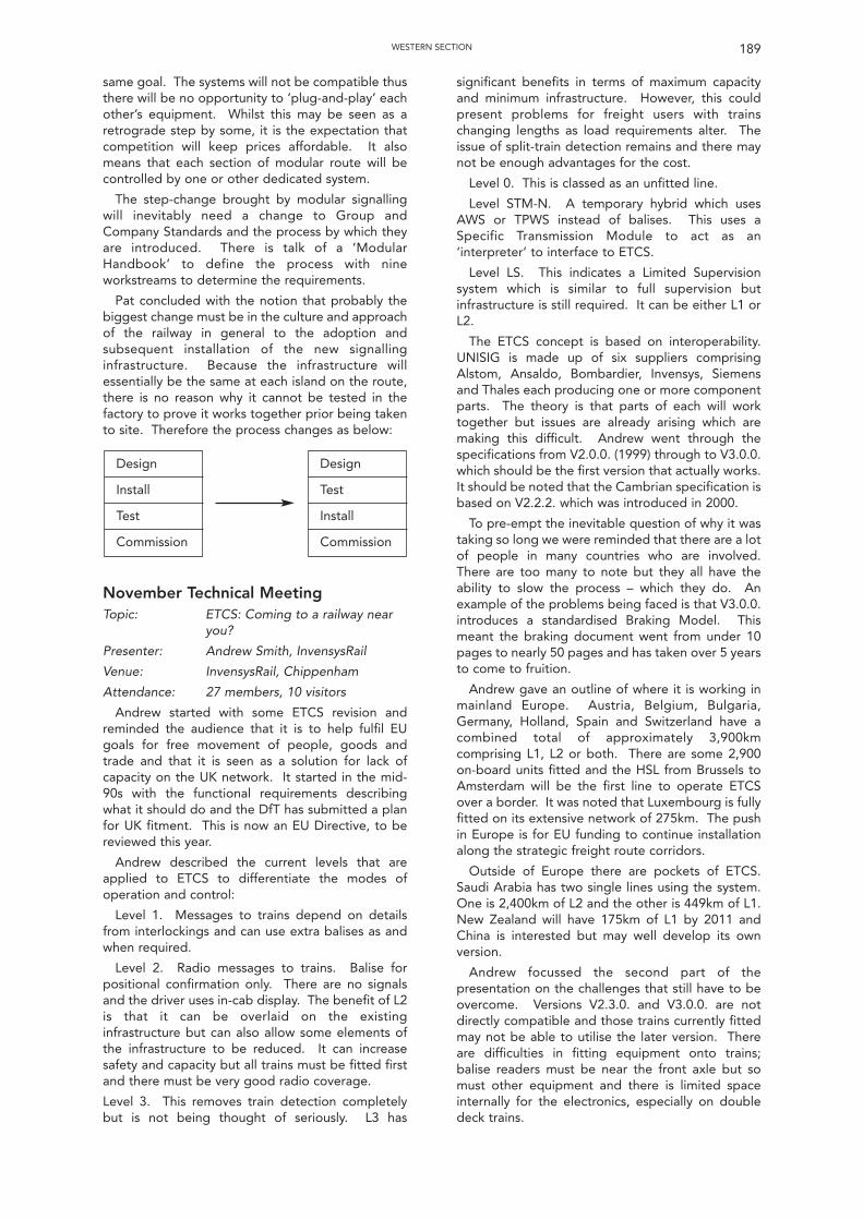
same goal. The systems will not be compatible thusthere will be no opportunity to ‘plug-and-play’ eachother’s equipment. Whilst this may be seen as aretrograde step by some, it is the expectation thatcompetition will keep prices affordable. It alsomeans that each section of modular route will becontrolled by one or other dedicated system.
The step-change brought by modular signallingwill inevitably need a change to Group andCompany Standards and the process by which theyare introduced. There is talk of a ‘ModularHandbook’ to define the process with nineworkstreams to determine the requirements.
Pat concluded with the notion that probably thebiggest change must be in the culture and approachof the railway in general to the adoption andsubsequent installation of the new signallinginfrastructure. Because the infrastructure willessentially be the same at each island on the route,there is no reason why it cannot be tested in thefactory to prove it works together prior being takento site. Therefore the process changes as below:
November Technical MeetingTopic: ETCS: Coming to a railway near
you?
Presenter: Andrew Smith, InvensysRail
Venue: InvensysRail, Chippenham
Attendance: 27 members, 10 visitors
Andrew started with some ETCS revision andreminded the audience that it is to help fulfil EUgoals for free movement of people, goods andtrade and that it is seen as a solution for lack ofcapacity on the UK network. It started in the mid-90s with the functional requirements describingwhat it should do and the DfT has submitted a planfor UK fitment. This is now an EU Directive, to bereviewed this year.
Andrew described the current levels that areapplied to ETCS to differentiate the modes ofoperation and control:
Level 1. Messages to trains depend on detailsfrom interlockings and can use extra balises as andwhen required.
Level 2. Radio messages to trains. Balise forpositional confirmation only. There are no signalsand the driver uses in-cab display. The benefit of L2is that it can be overlaid on the existinginfrastructure but can also allow some elements ofthe infrastructure to be reduced. It can increasesafety and capacity but all trains must be fitted firstand there must be very good radio coverage.
Level 3. This removes train detection completelybut is not being thought of seriously. L3 has
significant benefits in terms of maximum capacityand minimum infrastructure. However, this couldpresent problems for freight users with trainschanging lengths as load requirements alter. Theissue of split-train detection remains and there maynot be enough advantages for the cost.
Level 0. This is classed as an unfitted line.
Level STM-N. A temporary hybrid which usesAWS or TPWS instead of balises. This uses aSpecific Transmission Module to act as an‘interpreter’ to interface to ETCS.
Level LS. This indicates a Limited Supervisionsystem which is similar to full supervision butinfrastructure is still required. It can be either L1 orL2.
The ETCS concept is based on interoperability.UNISIG is made up of six suppliers comprisingAlstom, Ansaldo, Bombardier, Invensys, Siemensand Thales each producing one or more componentparts. The theory is that parts of each will worktogether but issues are already arising which aremaking this difficult. Andrew went through thespecifications from V2.0.0. (1999) through to V3.0.0.which should be the first version that actually works.It should be noted that the Cambrian specification isbased on V2.2.2. which was introduced in 2000.
To pre-empt the inevitable question of why it wastaking so long we were reminded that there are a lotof people in many countries who are involved.There are too many to note but they all have theability to slow the process – which they do. Anexample of the problems being faced is that V3.0.0.introduces a standardised Braking Model. Thismeant the braking document went from under 10pages to nearly 50 pages and has taken over 5 yearsto come to fruition.
Andrew gave an outline of where it is working inmainland Europe. Austria, Belgium, Bulgaria,Germany, Holland, Spain and Switzerland have acombined total of approximately 3,900kmcomprising L1, L2 or both. There are some 2,900on-board units fitted and the HSL from Brussels toAmsterdam will be the first line to operate ETCSover a border. It was noted that Luxembourg is fullyfitted on its extensive network of 275km. The pushin Europe is for EU funding to continue installationalong the strategic freight route corridors.
Outside of Europe there are pockets of ETCS.Saudi Arabia has two single lines using the system.One is 2,400km of L2 and the other is 449km of L1.New Zealand will have 175km of L1 by 2011 andChina is interested but may well develop its ownversion.
Andrew focussed the second part of thepresentation on the challenges that still have to beovercome. Versions V2.3.0. and V3.0.0. are notdirectly compatible and those trains currently fittedmay not be able to utilise the later version. Thereare difficulties in fitting equipment onto trains;balise readers must be near the front axle but somust other equipment and there is limited spaceinternally for the electronics, especially on doubledeck trains.
189WESTERN SECTION
Design
Install
Test
Commission
Design
Test
Install
Commission
There is much debate about what to do withsignals if they are retained. Should they be capableof being switched out, should they have additionalaspects fitted or retain their current aspects.Further, most interlockings are country (or region)specific and so not universally compatible.
There is also no incentive for the TOC/FOCs.ETCS means more equipment to fail but franchisesrequire it to be fitted and some trains e.g. steam,are probably too difficult to fit. Inevitably, somecountries want specific add-ons which will negatecompatibility and so ETCS could fragment withcountry or even project specific solutions. Anotherissue to be considered, but no one has reallyaddressed, is that of security encryption andencryption keys for ETCS and how they are to bedistributed and how often.
Andrew concluded with the following thoughts:
ETCS is coming – slowly
Some countries are faster than others – and havebetter funding
There is a Euro solution – possibly
It could be anywhere near you – maybe!
December Technical MeetingTopic: 9 ½ years of level crossings
Presenters: John Tilly, Senalizacion Ltd
Venue: Amey IS, Bristol
Attendance: 24 members, 9 visitors
The basis of John’s paper was some of the issueshe dealt with during the time he spent with HMRIspecialising on level crossings. He started bythanking Andrew Harvey, John Jenkins and others fortheir advice and assistance over that period. Beforediscussing his time with HMRI he gave a briefoverview of what are considered to be the six mostserious level crossing accidents in the UK, thosebeing Fenny Stratford, Naworth, Hixon, Beckingham,Lockington and Ufton. We were informed that in theUK there are about 12 fatalities per year on crossings,the majority of which involved pedestrians and forsome reason there is a particularly high percentage ofelderly males. John also pointed out that the UK’srecord of level crossing accidents is better than mostdeveloped countries. It appears that the accidentrate at level crossings accounts for approximately 1%of road traffic accidents in the developed world butin UK the accident rate equates to more like 0.4% ofroad traffic accidents.
John then went through a list of historical eventsfrom Level Crossing Acts, accidents, installation ofbarriers etc with the intention of showing howregulation shaped events and vice versa. Heexplained how the 2006 Road Traffic Act wasdelayed by some six months at Network Rail’sbehest whilst amendments were made to makeLocal Authorities accountable for road signage. Healso made us aware that since 2008 he, along withAndrew Harvey and others have been working withthe Law Commission to undertake a full review oflevel crossings and described some of the benefits,not just concerning safety, that can be accrued
through closure.
For the next topic John listed all the types ofcrossings found on the network and the subtledifferences between those that appear, on the faceof it, to be the much the same. He went through thebenefits and problems of each and made us awarethat AOCLs have a particularly poor safety record. Itis perhaps for this reason that Network Rail isunlikely to be able to renew AOCLs in a like-for-likeform and that conversion to ABCL is the minimumrenewal expected by HMRI. He then listed thecurrent legislation to which we must comply, thesebeing the Railway Clauses Consolidation 1845, LevelCrossings Act 1983, Level Crossings Regulations1997 and the Road Safety Act 2006, and the salientpoints that they cover.
John then moved on to a few of the crossings thathe has been involved with. The first was aparticularly difficult level crossing modernisation atBrittania Bridge on the Welsh Highland Railway.While there were some technical problems to beresolved, a lot of the problems arose around legalissues. For example, there was opposition andargument because the Level Crossing Order hadbeen signed by an English Secretary of State andnot the Welsh Secretary of State. A small section ofthe route has been classified as a tramway and assuch the drivers require a vehicle driving licence,and the lack of coordination between agencies hasled to the threat of a legal battle due to themovement of a path by 10 metres. As Johnexplained, all these matters could have been dealtwith by simple common sense but those involved donot seem able to recognise that fact.
An example of good cooperation andunderstanding was outlined for Mellionen crossing,again on the Welsh Highland Railway. The issue herewas the fear of children from the nearby campsiterunning on the lines. This was dealt with by theprovision of a vehicular crossing with cattle grids anda fenced in section leading to the crossing plus aseparate pedestrian crossing. This has worked wellwith no incidents in the year it has been in use.
Another simple application of common sense wasat Lincoln High Street crossing. This can see up to30,000 pedestrians per day on the crossing and whenit was renewed as an MCB CCTV crossing the timingfor the exit barriers were delayed by 10 second. Thisallows the large number of pedestrians to clear thecrossing and has proven to be very effective.
John described two crossings where the power ofthe law was used to initiate alterations. One was atBeddingham which had the worst risk rating on thenetwork. When the Highways Authority failed totake the risk seriously the power of the LevelCrossing Act was used to raise a Level CrossingOrder to force the issue with the Secretary of State.The culmination was the provision of a 1 ½ milebypass that was built over the railway. The otherwas at Hixon where the Health & Safety at Work Actwas used to force the issue of the provision of abridge that only cost £300k more than the cost of acrossing renewal and, in doing so, removed one ofthe worst crossings in the country from the network.
190 WESTERN SECTION
He then talked through what he considered to beone of the worst pedestrian crossings that he hadcause to come across which was at Mountsorrel.This crossing is over six lines on a twisting section ofroute at speeds up to 100mph. Under threat of aProhibition Notice Network Rail and LeFarge werehappy to cooperate but the local council were not.By informing them that as they had been madeaware of the nature of the problem and the risk of aNotice they had ‘guilty knowledge’ and could beliable, they had a sudden change of mind and anemergency closure order was in place within threehours.
John concluded his talk with a selection ofphotographs showing poor signage, and why levelcrossing owners are at risk of prosecution due to itand problems of poor maintenance to bothequipment and road decking.
John interspersed his talk with video clips whichmade clear some of the risks and actions undertakenby the public. These included a horsebox beingtowed over a crossing which was hit by a steamtrain. At only 5mph is demonstrated the potentialfor real carnage. Another showed a lorry beingdriven over a crossing with someone standing onthe load and lifting a protective wire put in place towarn against load contact with the overhead lines.A third video showed a youth jumping clear of atrain. It should be noted that the video evidenceallowed the perpetrators to be prosecuted.
February Technical Meeting (Joint with IET Local Section)Topic: The Tornado Story – from dream
to steam
Presenter: David Elliott, A1 SteamLocomotive Trust
Venue: InvensysRail, Chippenham
Attendance: IRSE and IET 24 members, 30 visitors
This was the annual joint meeting with the IETwith IET acting as sponsor.
David started the paper with a clip from YouTubeshowing Tornado running on the Settle to Carlisleline in full steam pulling a rake of carriages. Hestructured the talk with a brief introduction of thewhy the project had been started with a more in-depth talk as to how it had been undertaken.
The A1 Pacific Class was an A H Peppercorndesigned steam train to run on the LNER. 26 weremade in Doncaster and 23 were made in Darlingtonin 1948/49. They were very reliable and well builtand it was usual for the boilers to need renewalbefore the bearings and other mechanical parts.They were eventually scrapped due to the increasein the price of copper and the introduction ofdiesels. When it was decided to build a new A1, ateam of trustees and advisors were appointed.Among them was Dorothy Mather, widow of ArthurPeppercorn, who holds the post of President.
David then went on to describe how the projectcame to life starting with the engineering principleswhich were that it had to run on the main line, it had
to be as close to the original design where possible,it had to incorporate modern safety systems andhave the option to convert to oil firing in case futureemissions issues made it impossible to run on coal.
Around 95% of the required drawings were heldat York. They were mainly non-indexed andrequired electronic cleaning. Many had to bemodified or redrawn to make them useable. In all,some 1250 drawings have been scanned. Some ofthe problems found were that many drawings hadno tolerances, there was a lack of materialspecifications and that one drawing could covermany loco classes which led to incorrectmanufacture of parts. Material descriptions werevague and general which led to the use of two mainsources of information – 1957 LM region materialbook and the BR materials engineering department.
The metalwork part of the project started in 2005in GWR works but then moved to what was aderelict building in Darlington. The building wasrepaired and improved by Darlington Council andLottery funding for which project now pays a rent of£100 per year. Labour comprises 90% professionalengineers and 10% volunteers due to the need towork with new materials to close tolerances.
David described some of the managerial aspectswhich involved liaison with the Vehicle AcceptanceBody, HMRI (ORR), DfT for interoperability, NR andRSSB. The RSSB was particularly important as a lotof derogations needed due to the fact that a newloco could not comply with recent Standards.Because the project cannot run Tornado onmainlines by themselves they work with DBSchenker which has a steam safety case.
As with any project of this type there remains aneed for money – and lots of it. It has currently costover £3m which has come in the form of regulardonations and one-off donations and throughsponsorship. In one instance a bond issue raised£0.5m to cover the cost of the boiler. However, afurther £0.5m is required to continue funding futureoverhauls.
David then went on to talk about the manufactureof parts. This ranged from small industrial forgingunits in places like Dudley to large manufacturingplants in Europe who made the boiler. The boileralone took nearly a year to make and it is atestament to the people involved that the boilerfitted into the frame perfectly considering they weremade 500 miles apart. Other specialist workinvolved wheel manufacture and balancing toensure wheel loading was within the set limits toallow 90mph running. One particular issue to beundertaken was the change in design of the tender.This was altered to hold more water and less coal toallow for less frequent stops in running traffic.
The electrical system had three design principles –reliability, maintainability and safety + environment.There are several electrical systems availablecomprising a steam turbo generator, an alternatormounted on the tender and shore power. Thepower supplies are dual redundant and utilisecontrol and protection units mounted in the cab.These provide power for the OTMR and TPWS as
191WESTERN SECTION
well as other systems. The loco has an original AWSsunflower and the TPWS lights are incorporatedunderneath it.
David finished by giving a few facts and figures.Tornado first steamed in Jan 08 and its first movewas in Aug 08. It was tested on the Great CentralRailway which allowed running up to 60 mph and itsfirst test run was to Scarborough in Nov 08. Itcarried its first mainline passengers in Jan 09. It hassince been used on many public routes includinguse as the Royal Train plus many steam centres andheritage railways.
March Technical Meeting (Joint with PWI Local Section)Topic: Modular S&C – A signalling
challenge
Presenter: John Alexander, Network Rail
Venue: King’s Hotel, Newport
Attendance: IRSE and PWI members 14, 9 visitors
This was the annual joint meeting with the PWIwith PWI acting as sponsor.
John started his presentation by stating the trackchallenge of renewing a turnout (and have itworking) in an overnight possession and went on totalk of the difficulties of getting the signalling backin during the same possession. He alluded to thesomewhat unfair reputation put upon signalling asbeing responsible for delays as we are the last out.This is compounded by the need to be out of thetrack engineer’s way during the S&C renewal itselfbut having a target of 30 minutes to completehandback.
He then described the concept of modular S&Cwhich, it seems, is really very simple. Preparatorywork is undertaken in a series of possessions to prepand install new cables and a control loc case. Thenlift out the old S&C and prep the track bed. Nextbring in the new S&C on a tilting wagon that fitswithin our loading gauge. Finally lift the S&C off thewagon with a big crane which keeps the pre-madeset straight and level.
Whilst the theory is easy, the challenges are not.John went through some of the challenges includingissues of using new point operating mechanismswith differing supplementary detection, how thetrain detection can be reinstated in such a limitedtimescale, how to ensure the railway is safe tooperate following renewal and the need for highreliability in supplementary drives.
In order to meet these issues some requirementswere drawn up. These were to be able to interfaceany point operating mechanism to any controlsystem, to minimise alterations to power suppliesand to reduce testing on site due to extensivetesting and setting up at the manufacturer’s facility.In essence, what was needed was plug ‘n’ playfunctionality.
John talked through the steps of how such arenewal could be undertaken:
• Deliver control loc
• Parallel test with existing equipment
• Install wiring, cables and dis boxes ready forconnection to new S&C
• Remove old cables
• Slip links
• Cut track
• Remove old S&C
• Prep track bed
• Install new S&C
• Connect cables
• Operate and check detection under power
• Correspond to signalbox
• Job complete
In order for the above to be possible a set ofassumptions must be made:
• S&C is fully made and tested away from site
• All cables are fully set out to correct length
• All connections use plug couplers – includinghydraulic hoses
• Everyone buys into the plug, install and testmethodology.
However, some issues still remain. The onlyfeasible point operating machine is the in-bearerclamp lock coupled with ‘SO’ hydraulic backdrives.This is because the loading gauge is not sufficient toallow HW machines and mechanical backdrives tobe carried on the tilting wagons. This is driving thepolicy that would see IBCL as the preferred pointoperating mechanism but logic dictates that IBCL isnot suited to every location.
One area that has moved forwards is that of thepoint interface loc (PIL). It is envisaged that it willallow any point operating mechanism to connect toany control system in true plug ‘n’ play style. It willbe a standard loc with standard wiring that can berolled off a production line. It will have a battery toassist in driving the points and work is beingundertaken to see if the battery could power thewhole loc in situations where power is cut off. Thismight provide a MOM the ability to operate thepoints several times to keep traffic moving untilpower is restored.
An additional unit within the loc is theindication/control unit. Two teams of graduateswere tasked with designing a unit to assist in thespeedy installation and future maintenance of thenew S&C. One team chose a reasonably basicdesign with indication lamps for operation anddetection (up to six sets of detection that can bestrapped out depending on switch type). The otherteam chose a simple computer based system withan LCD message output. A benefit of the lattersystem is that it retains the last fault which shouldaid fault rectification. Indeed, the potential of theunit is such that Ops have requested that somethingsimilar be made available for use by MOMs.
John proceeded to discuss further issues that needto be resolved. These included whether an axlecounter or temporary TI21 in a suitcase could beused to allow train detection to be maintained in the
192 WESTERN SECTION
short term to allow completion of the renewal withinthe short duration possession with subsequentreconnection to the original track circuit in a follow-up possession. Another issue is that of connectingthe S&C into the plain line. It is probably notpossible to weld in time and so a policy decisionmust be formed as to when it will be welded.
The first use of the modular process was at OxfordNorth in mid-Feb 2010. The control loc did notinclude an indication box as this may have beenconsidered one step too many for early installations.Lessons learnt will undoubtedly improve the processand then it might be time to introduce it.
John finished his presentation by summarising theprocess as follows:
• Ensure site is suitable for modular renewal
• Use templated design to plan the work
• Install the PIL
• Install correct length cables/pipework withplug couplers
• Assemble equipment
• Undertake the renewal
• Carry out minimal testing
• Recover redundant equipment
April Technical Meeting (Rescheduledfrom January)Topic: Update on FTN
Presenter: Trevor Foulkes, Network Rail
Venue: Network Rail, Swindon
Attendance: Members 37, 13 visitors
Trevor started his presentation by giving anoverview of what the Fixed Telecoms Network (FTN)was. He felt that it is best described as being what wewould buy from companies such as Global Crossing orBT, namely a telecoms system infrastructure.
He then continued by identifying some of thethings that FTN will carry. These include GSM-R,electrification controls, signalling bearer circuits,operational and business telephony and radiosystems. It can also be used for TDMs and forms thebasis of the Network Rail Information ManagementWide Area Network or NRIM WAN.
Trevor showed how the network is built up usingpictures to indicate the core network of Telecomscentres and how it radiates outwards in rings withdifferent layers of the network consisting of differentring sizes.
The current S&T approach with cables is to filltroughing with all manner of cables with differingfunctions. This is particularly true of large renewalschemes where new routes may not be provided.The scope of the FTN project is such that it providesopportunities for signalling projects to get into thesystem provided the two can be effectively aligned.This is happening throughout the country butgreater use of FTN would lead to cost savings.
FTN is essentially made up of a series of layerswith copper at the bottom and the core layer, STM-16 at the top. Trevor described the layers in
different levels of detail as:
STM – 16. So called because it is capable ofspeeds 16 times faster than that of STM – 1. It is setup over the largest of the rings and utilises 24-fibrecables. The rings cover most of the network but afew places, such as Penzance, require BT closurelinks where the ring cannot close itself. There ishowever much debate over this as to some itpresents an opportunity for a break to occur. Thislayer is used for national applications such as TRUSTand for IECCs. It has a very high bandwidth and iscapable of auto-rerouting. However, it is onlyaccessible at a few locations.
STM – 1. Operates at 150Gb. Configured insmaller rings, it has core nodes at signalboxes andaccess nodes approximately every 8km. This ringlinks into the fibre cables. It has high bandwidth,auto-rerouting and can be used for remote alarms. Itcan be used for computer terminals and in the futurecould be used for remote operation of interlockingsor even disaster recovery of a signalbox.
Primary layer. It uses MUXs for variousconfigurations and can utilise modems and VFTDMs. It can be used for SSI circuits and acts as anISDN for speech and data. The primary layer couldmanage controls and indications and vital circuits. Itis resilient and allows for remote management butrequires power and equipment cabinet housings.
Copper. This is the bottom layer. Copper cablesare only installed where existing cables are lifeexpired. It has advantages in testing and powerapplications and will carry data up to 2Mb.However it is susceptible to damage, is expensiveand needs immunisation in electrified areas. It isused for control and indication circuits and could,theoretically be used for LED signals.
Trevor played a big role in developing a new typeof termination block that allows for fast connectionand where the centre of the block betweenterminations is removable to provide a direct accesspoint for testing.
Realising the extensive need for new troughing toput the FTN cables in, a super-armoured cable wasinvented. It was trialled at Northampton where itwas subjected to attack by chainsaw and burning byremnants of a rail weld. It was only finally damagedto the point it was unserviceable by being crushedby the buckets of a digger.
Having proved it could withstand being lefttrackside it is now run on the surface and peggedinto place. The use of super-armoured cable hassaved the project approximately £200m. Fibre isEMC immune and cheaper to install but is doesrequire skilled jointers to work on it.
Trevor went into detail of how the system can beconfigured and then how much the network hasincreased over a short space of time. It is now beingused for routing diversity. There has currently beensynergy with about 20 resignalling schemes withmore scheduled.
The cabling rollout is nearing completion and theproject team will then focus its attention on GSM-R.
193WESTERN SECTION
194
The York section membership stands at 365 out of4634 which represents 7.9% of the total IRSEmembership compared with 8.7% last year. In thisyear the York Section membership has shown asteady increase, however the main body of the IRSEhas increased at a higher rate, mainly, looking at theIRSE News, in overseas members.
The 2009/10 Committee consists of: -
Chairman J. Maw
Vice-Chairman D. Gillanders
Treasurer A.P. Smith
Visits Secretary K. Yews
Recruitment Secretary R.H. Price
Membership Secretary A.P. Smith
Secretary J. Maw
Committee I. T. MooreA. S. Kornas
R.A. PinkstoneK. Yews
The first meeting of this year’s session was byChris Hall of the RAIB who presented a paper on“Accident Investigation”. From 17 October 2005,the Railway Accident Investigation Board (RAIB)became the independent railway accidentinvestigation organisation for the UK and its solepurpose is to improve the safety of railways andprevent further occurrences. It was made clear thatit does not apportion blame or liability, nor enforcelaws or carry out prosecutions. Chris detailed theinvestigations that were carried out following aderailment of a freight train at Maltby and therecommendations that ensued. The biggest area ofrisk is the road/rail interface at level crossings. Anaccident at Wraysholme was investigated andrecommendations made which resulted in NetworkRail carrying out various modifications at thecrossing to improve safety. The RAIB hasinvestigated 144 accidents or incidents andpublished 126 reports, which has resulted in 753recommendations. 30 members and 1 guestattended this meeting.
The October meeting which was sponsored byNetwork Rail welcomed Dave Weedon who talkedabout “High Capacity Mainline Signalling throughthe Heart of London”. The Thameslink Programmeis not a signalling project but its primary purpose isto improve operational capability, to easecongestion & maximise potential. Dave explainedthat major stations have to be reconstructed andtrack layouts changed at Blackfriars, Farringdon,London Bridge stations. There is also a portfolio ofprojects of varying scope which include minorplatform extensions, huge civil constructions, ATOand resignalling works. Additional capacity is to beprovided by increasing train length to 12 cars,increasing the train frequency through the heart ofLondon from 8 to 24 trains per hour. This meetingwas attended by 37 members and 1 guest.
In December Martin Marsden presented his paper“Modular S & C – The Joint Approach”. Martin
outlined the problems with installing a typical S&Cunit; they are too long and too wide so are out ofgauge for rail delivery. To overcome this; a splice ismade along the length of the unit and it now can bedelivered in two pieces and re-assembled on site.This can be done in a 27 hour possession time. Forfull modular applications the aim is to install in 8hours, with the signalling element reduced to 30minutes! Within this 30 minute slot the testingconsists of wire count, strap and function test,gauging, full function test and final correspondenceand commissioning. 27 members and 5 guestsattended this meeting.
13 members and 5 visitors attended the firstTechnical Meeting of 2010, which was a paper byAndrew Plumb on “Automatic Control on HighCapacity Mass Transit Railways – Victoria Line”. Anoverview of the DTG-R (Distance to Go – Radio)system architecture as applied to the Victoria Linewas explained. The control centre, which maintainsthe timetable and provides ARS and ATR, sends routeinformation to a local site computer in each signallingequipment room (SER) which communicates with theinterlocking (WESTRACE). The Victoria Line uses twocontrol techniques to ensure high performance;stepped braking profile vs calculated braking profileand constant speed profile limiting. This meeting wassponsored by Invensys Rail.
In February, Steve Oldridge of Thales (meetingsponsor), gave a paper on “Manchester MetrolinkPhase 3A – An Infrastructure Project”. Steve beganby explaining the key figures of the project whichincluded; a route length of 32 Km (compared with37 for Phase 1), 27 stops (stations), trammaintenance and stabling depot at Trafford, and 2core Network nodes plus 41 at stops andsubstations. The Thales portion of the projectincluded system engineering processes across thewhole project, generic designs for E&M disciplinesproviding assurance for requirements compliance,ducting, bases for cabinets, equipment rooms, andOLE poles and substations. This meeting wasattended by 31 members and 5 guests.
The final meeting of this year’s session, in March,was by Richard Genner who gave his paper “If itbegins with N….It could be ours”. In this paperRichard dealt with the resignalling projects atNuneaton, Newport and the North London Line.This meeting was attended by 26 members and 3 guests.
The average attendance for the six TechnicalMeetings was 31, which is a very creditable figure.
As a follow up to the paper on “AccidentInvestigation” given by Chris Hall in the last session, anumber of members of the York section visited theDerby offices of the Rail Accident Investigation Branch(RAIB) during the summer. After a brief presentationexplaining why the RAIB was founded and the scopeof their investigations we were given a tour of theirfacilities and presentations on a number of accidentsthey had investigated. This included an investigationof why a train had derailed at a level crossing. It was
York Section
only after the investigators reviewed the CCTVpictures and visited the site they determined that aroad vehicle had lifted the level crossing road surfaceand when a train came by this piece of materialderailed the train. The RAIB also showed ourmembers their response vehicles, which apart frombeing fitted with tools, had access to all the main TVnews media channels, and aerials for all the majormobile phone networks, ensuring communicationcould be maintained at almost any point in thecountry. It was a very interesting and informative visitand we were grateful the RAIB gave us their time toshow the work involved in accident investigation.
The finances of the York section were reviewed forthe previous year by Andrew Smith. In 2009 the YorkSection received no sponsorship for any of the talkswhich were given in 2009. The Income andExpenditure accounts for 2008 and 2009 both showslight losses with regard to the holding of the talks,but this is hidden amongst the dinner costs. TheProfit & Loss accounts uncover this. The issue wasnot helped by the sponsorship from Network Rail,which was apparently paid, but never reached ouraccount. We have been unable to find where it went.The same has happened this year and we are stillinvestigating what has happened. However, thisdoes not cover up the fact that in 2008 we had anear £1500 profit on our activities, but getting on for£1700 loss last year. Whilst we still have money in thebank, we clearly cannot let this happen for very long.We suspect that it is evidence of the downturn in therail industry, further evidence of which will appear innext year’s accounts in a significant loss we haveincurred from this year’s Annual Dinner as a result ofthe late withdrawal of one company. The precise sizeof this loss is currently unclear but is likely to be inthe order of several hundred pounds We will have toconsider very carefully where to hold next year’sdinner as without being able to expect a minimumnumber of attendees we have to pay a room hirecharge as well as the dinner cost, which would havean impact on the price of the meal.
Whilst it is to be hoped that we may receive moresponsorship in the next session, I do not hold outgreat hopes and fear that we are possiblyapproaching the time when we have to eitherreconsider how we carry out our activities, orapproach Council for sponsorship as we used to do.This, too, is something for the committee toconsider in the next session.
However, to end on a positive note, once again Iam very grateful to Ernie Thomson for auditing theaccounts.
This year’s selection of papers has reflected thework of three of our local section members. MartinMarsden gave a talk on The Modular approach toS&C renewals and it was interesting to include workcarried out by our Civil Engineering colleagues aswell as Signalling. On our “Metro” subject SteveOldridge talked about the extensions to theManchester Metrolink. Richard Genner gave us our“Project” talk about the work in Wales. Othersubjects were “Accident Investigation” by ChrisHall, always a popular subject although thankfully it
has been a number of years since the UK railway hassuffered a major accident. The topic of HighCapacity signalling was covered in The ThameslinkProject by Dave Weedon whilst Mass transit byAndrew Plumb, presented Automatic control asapplied to the Victoria line.
We have tried to make the subjects of our talks ofinterest to signal and telecommunicationsengineers, and this year have also managed toattract a few from the operators as well. Each yearthe Committee tries to make the talks as wideranging and interesting as possible but it oftendifficult to persuade speakers that their subject willbe of interest and the incoming chairman alwaysworks hard to come up with subjects that willhopefully prove of interest. The talks this year havebeen generally well attended with the possibleexception of January. I think that this was more todo with the bad weather than the subject of the talk.
Again there has been a lack of interest in thecommittee. I can only repeat what Andrew Smith saidlast year that this is very definitely the one route in ourinstitution’s life which all members of the York sectionhave the opportunity to influence, and yet year afteryear we end up with the same group running thesection because no one shows any interest inreplacing us! This year Rod Price has decided to stepdown after more than 16 years on the Committee, atleast 11 of those as the organiser of the dinner dance,no mean feat in itself. The Committee would like topass on our thanks to Rod for his years on theCommittee and for his support and guidance.However as I have already said no-one has steppedforward to replace him. It’s true that an IRSE SectionalCommittee is unlikely to change IRSE policy, buthopefully it can provide influence upwards.
This year’s dinner dance was again held at theRoyal York Hotel. Although numbers were down onlast year it was a thoroughly enjoyable occasion.
On this point I would like to thank Rod Price fororganising the dinner. As I said previously he hasmore or less single handedly organised the Sectiondinner dance for the last 11 years or so and it can bea somewhat thankless task as people drop out at thelast moment especially after agreeing a number ofplaces.
Likewise, I would like to thank Keith Yews forcontinuing to organise visits. Visit venues are almostas hard to find as subjects for talks as the health andsafety police become ever keener. I have not beenable to make any of last years visits, but hopefullynow that I am fully retired (?) I will be able to enjoythe forthcoming visits this summer. Againsuggestions for visits would always be welcome.
I would also like to pass on my thanks to theCommittee without whom none of the talks wouldhave happened.
Finally my best wishes to Doug Gillanders as hisfirst stint as Chairman of the York Section begins forthe coming session.
John Maw Chairman 2009/10
195YORK SECTION
196
Younger Members’ SectionThe Younger Members of the IRSE continue to
flourish, with a number of extremely successfulevents being held during the last session. The yearstarted with a Module 5 exam preparation day inRugby in July and a Module 2&3 exam preparationweekend in Derby in August with approximately 60engineers attending each and gaining vitalinformation and practice in preparation for theforthcoming IRSE examinations. This was followed inNovember by a two day Seminar & Technical visit inYork. Day one packed in a number of signallinglectures with day two covering a visit to Invensys toexplore their new technology and a trip to YorkIECC or a demonstration of Absolute Block workingat the National Railway Museum. The New Yearbrought our traditional Half Day Seminar, whichincluded the AGM and exam review. May saw anearlier start to the exam preparation workshops for2010 with another Module 2&3 weekend in Derby.
IRSE EXAM MODULE 5 PREPARATIONDAY
Throughout the years of the YM Exam Review,requests for practical help have constantly beenfiltering through to the committee. The 2009-10season kicked off with a Module 5 preparation dayheld at GM Rail’s facilities in Rugby and offered arange of sessions for young engineers to haveclassroom based discussion around principles andpast exam questions followed by the chance tomake use of the equipment available at GM Rail todemonstrate application of principles. Our thanksgo to GM Rail and all the volunteers who made thisday possible.
IRSE EXAM MODULES 2&3PREPARATION DAYS
Following on from the success of the Modules2&3 workshops in 2008, another Module 2&3 examworkshop was held in the summer of 2009. The 2day session was held at Signet Solutions in Derby onthe weekend of the 15th and 16th August 2009.These sessions helped over 60 young engineers intheir preparations for these modules. An early startwas made to the 2010 exam preparation withanother 2 day session at Signet Solutions in Derbyon the weekend of 8th and 9th May 2010. As thisevent was a little earlier than those that were run inprevious years, it was decided to focus more on ageneral exploration of signalling principles ratherthan purely focussing on particular exam questions.Many thanks to Reuben Daken & Mark Naylor ofSignet Solutions and Peter Woodbridge of InvensysRail for their time and support over this weekend.
SEMINAR AND TECHNICAL VISIT(YORK)
The annual YM conference in 2009 was held on12th and 13th November 2009 at the York NationalRailway Museum. The conference took the format ofa seminar (12 November) and technical visit (13November). 110 delegates attended the seminar
where 7 presentations covered signallingtechnology old and new from the origins ofsignalling principles through to ERTMS as well asmetro input, concluding with enthusiastic debate.The technical visit was held at Invensys Rail’s officesat Saxby House where a talk and presentation weregiven on SSI, WestLock, WesTex and WestCAD; thiswas followed by the choice of either a visit to YorkIECC or a demonstration of Absolute Block at theNational Railway Museum.
AGMThursday 28th January 2010 saw the annual event
of the YM AGM, Seminar and Exam Review. Theevent took place at the IRSE headquarters inLondon and 50 delegates were present.
The YM committee had two resignations, ourChairman Lynsey Hunter and Publicity SecretaryOlga Wisniewaka. Our thanks go to them for all theirhard work contributing to the success of theYounger Members section.
We are pleased to announce the new committee:Chairman – Martin Fenner; General Secretary – TomRobinson; Treasurer – Andrew Witton; PublicitySecretary – Ian Ettle.
LECTURESFollowing the AGM, Roy Butchart of Catalis gave
a presentation on the past, present and future ofS&T training on the UK Mainline Railway. This wasfollowed by Kenny Doggett who gave a talk onYounger Member International Technical Visits.
Peter Martell of Amey Rail then presented anentertaining session entitled “Rules – For TheGuidance Of Wise Men And Adherence Of Fools”.
The final presentation was given by MathewLupton of Atkins who discussed Braking and Brakingcurves asking; Where Will It Stop?
EXAM REVIEWThe exam review directly followed the AGM, and
was attended by many who either sat the exam theyear before, or were planning on sitting it next year.This session is invaluable as many of the examineesdo not understand where they went wrong, andthey can have a chance to ask questions of theexaminers directly. The Younger Members aregrateful to all the examiners for the time they spendat the review.
YOUNG RAILWAY PROFESSIONALSAn exciting new group has been formed this year
from the Young Members sections of the maininstitutions that form the Railway Engineer’s Forum(REF) namely the IRSE, IRO, IMechE, IET and PWI.This group was launched under the banner of YoungRailway Professionals (YRP) at a formal black tiedinner on the 4th February 2010 held at 1 BirdcageWalk in London with a sell out 150 delegates inattendance.
The YRP has been set up with three aims: toPromote, Inspire and Bring Together. To Promote
197YOUNGER MEMBERS’ SECTION
the best events being held by the institutionsrepresented to the YRP network, to Inspire youngrailway professionals to actively continue theirprofessional development by giving them access tosenior industry figures, and to Bring Together byorganising national and international networkingevents for all railway staff.
More information about the YRP can be found onwww.youngrailwayprofessionals.org
The website also includes a forum for discussion,and allows for free subscription to the YRPnewsletter.
SESSION 2010-2011As we move into the next session, plans are
already forming for the opportunities we want toprovide to our members. Significant planned eventsinclude a Younger Members seminar and technicalvisit to be held in London on the 12th and 13thNovember 2010.
Study days will be held for IRSE Exam Module 5 inAugust with the AGM and exam review in January.
There are currently plans to hold an InternationalTechnical Visit to Stockholm in February/March2011.
If you would like to be included on our mailing listand receive details of our upcoming events, pleasesend an email to [email protected].
COMMITTEEThe sterling work that the Younger Members’
achieve throughout the year could not bemaintained without the tireless enthusiasm of thecommittee members. The committee compositionchanges yearly, and is always open for newmembers/helpers. It is only with your support thatwe can continue to deliver what the YoungerMembers require.
The committee members for the 2009 - 2010session were as follows:
Chairman Lynsey Hunter, Network Rail
General Secretary Martin Fenner, London Underground
Treasure Andrew Witton, Network Rail
Publicity Secretary Olga Wisniewska, Lloyds Register Rail
YM forum Champion Madiraju Ananthudu, McML Systems
Management Committee Representative John Haile, Thales
Many thanks to all of the committee members,and also those non-committee members who haveworked and supported the Younger Members overthe past year. If you are interested in becominginvolved with the Younger Members, please contactany member of the committee.
Tom Robinson

Advertisers
Page
DeltaRail ………………………………………………………………………………………………………………………………………………………………………………… ifc
Bombardier ……………………………………………………………………………………………………………………………………………………………………………… 2
Henry Williams ……………………………………………………………………………………………………………………………………………………………………… 11
Kelly………………………………………………………………………………………………………………………………………………………………………………………… ibc
Atkins Rail ……………………………………………………………………………………………………………………………………………………………………………… bc
198

199

200
The Editor would like to thank Linda Mogford, Peter Grant, Colin Porter, Frans Heijnenall the UK and Overseas Section secretaries and the staff of
Fericon Press, Reading, for their assistance and co-operation in the production of theProceedings. The Institution is also most grateful to our colleagues within
the signalling industry who have kindly supported the Proceedingsby placing an advertisement.
Plan Design Enable
As one of the country’s leading signalling design houses, Atkins has the skills and capacity to successfully deliver complex resignalling projects which will improve the UK’s railway infrastructure.
Thanks to a proven track record and a commitment to technical excellence, our expertise is currently being utilised on a number of significant programmes both in the UK and overseas, including Newport Area resignalling scheme and the implementation of ERTMS across the Danish network.
Signalling Specialists
Consultancy Design Testing Installation Commissioning
[email protected]/railandmetro


![(2010) · 2010. 8. 3. · Detailaruanne[30.07.2010 13:07]: Riigikogu liige: Aivar Riisalu, Kululiigid: kõik € € jaanuar (2010) veebruar (2010) märts (2010) aprill (2010) mai](https://img.pdfslide.net/doc/110x75/6106a7003ec91d28267f3cc7/2010-2010-8-3-detailaruanne30072010-1307-riigikogu-liige-aivar-riisalu.jpg)