Embed Size (px)
Citation preview

Disclosure to Promote the Right To Information
Whereas the Parliament of India has set out to provide a practical regime of right to information for citizens to secure access to information under the control of public authorities, in order to promote transparency and accountability in the working of every public authority, and whereas the attached publication of the Bureau of Indian Standards is of particular interest to the public, particularly disadvantaged communities and those engaged in the pursuit of education and knowledge, the attached public safety standard is made available to promote the timely dissemination of this information in an accurate manner to the public.
इंटरनेट मानक
“!ान $ एक न' भारत का +नम-ण”Satyanarayan Gangaram Pitroda
“Invent a New India Using Knowledge”
“प0रा1 को छोड न' 5 तरफ”Jawaharlal Nehru
“Step Out From the Old to the New”
“जान1 का अ+धकार, जी1 का अ+धकार”Mazdoor Kisan Shakti Sangathan
“The Right to Information, The Right to Live”
“!ान एक ऐसा खजाना > जो कभी च0राया नहB जा सकता है”Bhartṛhari—Nītiśatakam
“Knowledge is such a treasure which cannot be stolen”
“Invent a New India Using Knowledge”
है”ह”ह
IS 10086 (1982): Specification for moulds for use in testsof cement and concrete [CED 2: Cement and Concrete]


Gr 5
IS: 10086
Indian Standard Reaffirmed 2008
- 1982
SPECIFICATION FOR
Reaffirmed 2004
MOULDS FOR USE IN TESTS OFCEMENT AND CONCRETE
Third Reprint MARCH 2008( Including Amendment No, 1,2.3,4 & 5 )
UDC 666.9055: 621.744.3 : 620.173/.174
© Copyright 1982BUREAU OF INDIAN STANDARDSMANAK BHAVAN, 9 BAHADUR SHAH ZAFAR MARG
NEW DELHI 110002
August 1982

IS : 10086• 1981
Indian StandardSPECIFICAnON FOR
MOULDS FOR USE IN TESTS OFCEMENT AND CONCRETE
Cement and Concrete Sectional Committee, BDC 2
CluzirmtlllDR H. C. VrSVESVARAYA
Membn,
RepresmtUltCement Research Institute of India, New Delhi
Central 8011 and Materials Research Station, NewDelhI
Hyderabad Asbestos Cement Products Ltd,Hyderabad
Engmeer-m-Chref '5 Branch, Army Headquarters,New Delhi
The Concrete ASSOCiation of India, Bombay
Geological Survey of India, Calcutta
Central Pubhc Works Department, New Delhi
The Associated Cement Companies Ltd, Bombay
] rriganon Department. Government of Punjab,Chandigarh
SHRt S N, PANDE (Alternate)DR R R HATTIANGADI
SHRIP.J.JAGUS (Alternate)
SURI V. K. GUPTA
DIRECTOR, IPRI (Alternate)D,REGTOR (CSMRS)
D&PUTY DIRECTOR ( CSMRS )( Alternate )
SHRIT. A E. D'S"SHa. N. C. DUGGAL ( Alterant, )
SHRJ A. K GUPTA
ADDITIoNAL DIRECTOR, STANDARDS Research, Dengns & Standards Organiaaticn(B & S) ( Ministry of Railways), Lucknow
DEPUTY DJRECTOR, STANDARDS
( B & S) ( AI'm"," )SHRI K. P. BANERJEE Larsen & Toubro Ltd, Bombay
SHRJ HARISH N. MALANI (Alternale)SaRI S. K. BANERJEE National Test House, CalcuttaSHill R. N. BANSAL Beas Designs Orgamaanon, Nanga! Township
SHRI T. C CARG (Alurnau)SHRI R. V. CHALAPATHI RAO
SHIn S. RoY ( Alternate)CHIEF ENGINEER ( DESIGNS)
EXECUTIVE ENG I NEE Il( DESIGN.) III (AI,,,,,,,,,)
CIlIEF ENGINEER ( PROJECTS)
( Continued on page 2 )
• Copyrigh, 1982BUREAU OF INDIAN STANDARDS
Thte publication IS protected under the Indian Copyright Art (XIV of J'57) andreproduction ID whole or ID pan bv any means except With written perrmsaen or tb.publisher shall be deemed to be an tnfrmgement of copynght under the .ald Act.

IS ; 10086 - 1981
(Cont,nued/rom pa,. 1 )
Membtrs Repnmdmg
D. IQBAL Au Engineering Research Laboratortea, HyderabadSHaI S. R. KUL&AR~I M. N. Dastur & Co Pvt Ltd. CalcuttaSHill S. K. LARA The Inantuuon of Engineers ( India ), Calcutta
SUR' B. T. UNW'ALLA ( Altn-natt)DR MOHAN RAJ Central Budding Research Institute ( CSIR),
Roorkee
In personal capacity (C RamorroltJYd I J1 First ern",,'Park Road. Gandhmogar, Adyo,. Madras J
Hmdustan Prefab Ltd, New Delhi( A./temnle)
Central Road Research Institute (CSIR J. NewDelhi
SHRr M R. CHATTERJEE ( ALtmlate I )SHRI K. L SETHI ( Altmzote II )
Oil M RAMAIAH Structural Engineering Research Centre (CSIR),Roorkee
SHill H 5 PA-SRICHASURI C. S. MIStlRA
SHill Y R. PnULL
D. S. S RBMII ( Alterna',)SHill K. K. NUfBIAR
Directorate General of Supplies and DIsposals. NewDelhi
National Buildings Organization, New Delhi
DR N. S. BHAL ( A/Innate)
SHRI G. RAMO AS
DBA. V. R RAOSHRI J SEN GUPT.... ( Alltrnate )
SHRI T N. S RAO Gammon India Ltd, BombaySHRI S. R. PINHEIRO (Alternate)
REPRESENTATIVE Indian Roads Congress. New DelhiSHal ARJUN R'JHSINGH NI Cement Corporation of India Ltd, New Dellu
SHRr K. VITH .... t. R o ( Alternate)
SECRETARY Central Board of Irngation and Power, New DelhlDEPUTY SECREtARY (I) ( Alternate)
SHRI N SlVAGURU Roads Wmg, MInistry of Sb1ppmg and Transport.New Deihl
SHRI R. L. KAFOOR ( Alternate)SHRI K A. SUBRAMANIAM The India Cements Ltd, Madras
SHRI P. S RAMIo.CHANDRAN ( Alternate)SUPERINTENDING EN 0 I NEE R Public Works Department, Government of Tamil
(DESIGN5) Nadc, MadrasEXECUTIYE ENGINEER ( SM&R
DIVISION) (Alternate)
SURI L. SWAROOP Dalmia Cement (Bharat) Lui, New DelhiSHRI A V. RAYANA (Alternate)
SH'" G. R",,,,,,'N, Du:ec\ot Genenl. lSI (,E:c-officw MtnW-n)Director (Civ Engg )
SUiTe/MY
SHRl M N. NEELAKANDHAN
AssIStant Director (Civ Engg), lSI
( Continued 01.1 fJa'.e 19)
2

tlE;r) AMENDMENT NO. 1 NOVEMBER 1984TO
IS:10086-1982 SPECIFICATION FOR MOULDS FOR USEIN TESTS OF CEMENT AND CONCRETE
Addendum----(RzgB 14# TablB Z) - Add the following new note
below the table:
'NOTE - The length and width of base plate dependupon the arrlLll6ement provided for clamping the lIIouldto the base plate and hence lII&y vary f'1'OIII the valuesspecified in the table.'
(BDC 2)Printed at Simco Printing Pr.... Deihl, Indle

Al"1ENDI4ENT NO. 2 JUNE 1~5TO
IS:10086-1982 SPECIFICATION FOR MOULDS FOR USE INTESTS OF CEMENT AND CONCRETE
(R:rge 4. clause 4.1) - Renumber the existing NOTEas NOTE I and add the following as NOTE 2 under thisclause:
'NOTE 2 - For checking the permissible variationin the planeness. the surface should be Wholly conta.ined between t \lO plane s not furt her apart than thespecified value.'
(IDC 2)

AMENDMENT NO. 3 FEBRUARY 1988
TO
IS: 10086-1982 SPECIFICATION FOR MOULDS FOR USEIN TESTS OF CEMENT AND CONCRETE
(Page 17, clause 7.1, line 2) - Add the words'and the accessories' after the words 'the mould'.
(Page 17, clause 7.1. 1) - Add the words 'andthe accessories' after the words 'The moulds'.
(BDC 2)
Printed at Simco Printing Pr..., Deihl. Indl.

AMENDMENT NO.4 MARCH 1993TO
IS 10086: 1982 SPECIFICATION FOR MOULDS FORUSE IN TESTS OF CEMENT AND CONCRETE
(Page 4, clause 4.1) - SumlilUle 'IS 2102 (Part 1 ) : 1980' for 'IS: 21021969' In rbe NOTE.
( Page 4.{00I-nore) - Subsutute the following forlbe exrsuag foot-note:
" GenerallOleraDCtS for dilDeDS10DS aDd form ,nd position: Part 1 Geaerallolcrances [Of hour .nd
angular dimuSJODS ( s«OIlI nMS"UM ) •
(CED2)Pnnted at Snnco Pnntmg Press, Oelfu

AMENDMENT NO. 5 JULY 2006TO
IS ]0086: ]982 SPECIFICATION FOR MOULDS FORUSE IN TESTS OF CEMENT AND CONCRETE
( First cover page) - Insert the following above the English bile of theInman Standard
'wrrfP-r JfRCfi
~ am~$~.r~~ q,1 fqf~lfte'
(CED 2)
pnnted at Simco Printing Press. Delm

1S : 10086 - 1981
Indian StandardSPECIFICAnON FOR
MOULDS FOR USE IN TESTS OFCEMENT AND CONCRETE
o. FO R E W OR D
0.1 ThIS Indian Standard was adopted by the Indian Standards Institutionon 28 January l 982, after the draft finalized by the Cement and ConcreteSectional Committee, had been approved by the CI\ 11 Engmeenng DIVISIonCouncil.
0.3 The Indian Standards Instttutton has already published a sene, ofstandards on methods at' tc.nng cement and concrete. It has beenrecognized that reproducible and repeatable test results can be obtainedonly With standard tesung equipment capable of givmg the desired levelof accuracy The Secuonal Committee has, therefore. decided to bnng outa sene, of specIficatIons covering the require-nents of equipment used fertesting cement and concrete, to encourage their development and manufacture in the country.
0.3 Accordingly, this standard has been prepared to cover requirements ofthe moulds used for c.isung cement or concrete cubes, cylinders and beamsfor compressive and flexural strength tests on cement and concrete. TheIndian Standards which detail the method, of compressive and ftexuralstrength tests requiting use of these moulds are IS: 516-1959.,IS: 1I99-1959t and IS : 4031-1968t-
0.4 In the formulatton of tlus standard, due werghtage has been given tomternational co-ordination among the standards and practices prevailingm different countnes m addiuon to relating It to the practices In the fieldin tlus country.
O.S For the purpose of decidrng whether a particular requirement of thisstandard IS complied With, the final value, observed or calculated, expressing the result of a test or analysis, shall be rounded off In accordance WIthIS: 2-196O§. The number of SIgnificant place retained In the rounded offvalue should be the same as that of the specified value In thrs standard.
• Methods of test for strength of concrete
j Merhods of samplmg and analysis of concretetMethods of phyncal tests for hydraulic cementqRules for rounding off numerical values ("t1J-'d)
3

IS : 10086- 1m
1. SCOPE
1.1 This standard covers the requirements of the moulds used for castingcement or concrete cubes, cylinders and beams for tests of cement andconcrete, such as compressive strength test and llexural strength test.1.1 Moulds which are accessories to testing equipment such as vibrationmachine and joltmg apparatus are not coverd by this standard.
2. TYPES
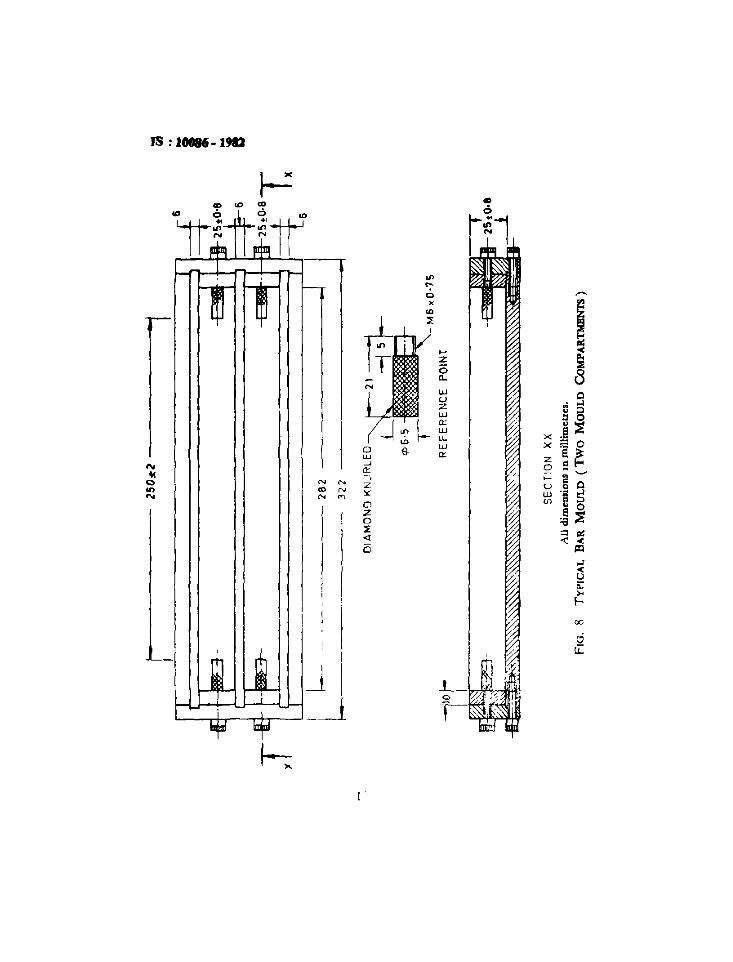
2.1 The moulds shall be of following types:a) Cube moulds of 50, 100, ISO, 225 and 300 mrn,b) Cylindrical mould of ISO mm diameter and 300 mm height,c) Beam moulds of 100 x 100 x 500 mm and 150 x 150 x 700 mm,d) Bar moulds of 25 x 25 mm Size and 2~0 mm effective length, ande) Mould of 75 x 75 mm me and 150 to 300 mm length.
3. MATERIAL
3.1 Matenal for construcuon of moulds shall normally be as given inTable I. However, any other material which is non-absorbent and nonreactive with concrete and which shall retain the dimensional stability ofthe moulds may also be used.
4. DIMENSIONS AND TOLERANCES
4.1 The dimensions with tolerances of vanous types of moulds describedat 2.1 (a) to 2.1 (d) ( See FIg I to 8 ) shall be as given in Tables 1 to 5. Thedimensions of moulds described at 2.1 ( e) shall be such that It shall bepossible to cast specimens with a length of 150 to 300 mm and a cross-secnon as near as practicable to 75 x 75 mm.
Non - The allowable deviations for nominal dtmensrons shall be as laid down forcoarse class of deviation In]S 2\02·1969·,
5. CONSTRUClION
5.1 General - The construction of the moulds shall, 10 general, be inaccordance with Fig. I to g
NOTE - The figures are rlluerrauve only, but the dimensions and mmimum requirements where specified shall be bmdmg
5.1.1 The moulds shall be of metal and stout enough to preventdtstortion. These shall be constructed in such a manner as to facilitatethe removal of the moulded specimen WIthout damage and shall be SO
machined that, when they are assembled ready for use, the dimensions andInternal faces shall be accurate WIthin the specified hrmts, Internal faces ofthe moulds shall be smooth.
·Allowable devrancns for dimensions Without specified tolerances (first revISIon).
4

IS 10086. 1981
0....:>
'" 0~ ~
:E~
..'"
1\:>U
, .------- .. ---- ----~
,
-,I
iII
:I
I,,I,,iII,if--L------:::::=::::=-=-=-JII
o
•
s

~ : 10086 - 1981
~::.~----~=-:.:.:..- ---n-- __l:.:'==-:"_ --" ---~=!:==)
'".,o'"
• I,
n
;::::==,---- ~f---------- .uf----- -~-,J -----,-l r :----, r---'" L. .......
J Jy
--I,I,I,I,,I
r tL'
/'<..lOCATING/ ~PIN
6..o
"'
~~~~~~~All dimensions In nulhmetres
FIG. 2 TYPICAL CUBI! MOULD, SOmm SIZE WITH 3 MOULD COMPARTMENT
6

IS : 10086 • 1982
CAPPING PlAIf
f---- 'I>195.2 ----c~
~
~ -o. ~
00~
~+-~
-i,
¢ 300:!) I ~BASEPLATE
AU dlDlemions in mdlimetre;.
Flo. 3 TYPICAL CYLINDIUCAL MOULD
7

IS : 10086 - 1981
0....;:,
~
.. :l':is/Xl....-eo0:~
....
~
'j
8
I-'
rr=:~1 .;.;..,,--'
rwr - ------,"1f =:I;~ o~ - r-,+-_1
: I-;;'~ II~r.±-.../.-I: ~ : I'
J! :,[31 i iiii
1r.:.x--l.ll I !I I,~': il 'I I ..,.
I I, II II I
I I :
Irf@-,*,"-L,i,,;I: 1M-1--:@l'!", "'-"~": : -=-1 I
, ' I ': : I I' i
: : I :!
~:i i I
") .U' :! ~ I :I ,...' - II 0"'- I
: I o~ ',,1 i I
~P:' ~~~r i i"----- IJ

IS : 10086 - 1932
Q....;:>
0 0
'"0 .....~ '"2
-e~
x.5 ....x -e
z a o0
~0:,.
u u f-w E'" :;; V)
:;;: o::L:
Flot ------r
N.. N~0 e ..
'" N NN
I
'"IIf'I ,
hlett-~Jrl
9

IS : l008Ci - 1981
-
Ie,::>:
8
wuzw
"w...w
'"
m--
~1
I I, I
:. I,.C N ~
~ ....~ N ~
I
I:J
10

IS : 10016· 1JID
'"e-0...,::[
z0Q.
wu 0z '"'w . ;>
~Ill: ~ 0
~:::w
l ~u.w )( ..
o '6 Ill:)( <
8 ~w z~ Q ~ ....Ill: <::> u a oz w g it
'" l/l a ,.0 " I-z §0 -0 r-::[ ;;;.. e0 ;;::
JIlIq
-- l[
N... N .,N OIl 0... N '"N
J[I
-I.jd
t I
fiI I , !8 6 .8T
:'---2
82
.1I
322
-
1-2SD~2
"I
Lk--
._-
T
LIi
.~
-'1=
==f-6
Ee-
L
-'
r~
..~.
-tl-2
1tO.
lLI
L...J
--t
-'
m-;T
_.--
.,
.2
5,'
--=to
xT
M6
.0·7
5P
OIN
T
<1>6
·5
DIA
MO
ND
KN
UR
LED
-,
1,"1-
~"'.'
£~~~
.-."
'~~~
SE
CT
iON
XX
AU
dim
ensi
ons
Inm
illi
met
res.
FIG
.8
TY
PIC
AL
BA
RM
OU
LD
(Tw
OM
OU
LD
Co
MP
AR
TM
EN
TS
)

IS , 1001/6 - 19H2
TA.BLE I MATERIA.LS OF CONSTRUCTION OF MOULDS
(Clau" 3.1)
SL MOUlD TYPE PART :'\fA1EI~lr\1 RI!:(,O'l\IL'OFD
No. 1.... DI',·.
ST,\NDARD
"oP1::Cll'lC \T1O\.,
IF "NY
(1) (2) (3) <-I, <}\
I) Cube mould, 50 mm a) Side plate Cast )fonl IS' 210-1978*/Mild su-e! I, 226-1975t
b) Base plate Cast Honf T'i 210.1978-/Mild st. e] T' .!~(;-1l)75t
11) Cube mould, 100 mm, a) Stele plan Cast ICOn I' 2IU-1978~J50 mm, 225 mm b) RHe piau- C ..ut Iron 1\·21O-jlJ78"and 300 nun
111) Cylindncal mould. a) Spilt part Cast Iron: i-, 21/,-1978-150 mm diameter X Mild steel IS ~26-197Jt300 mm height b) Base plate Cast Iron! I" 210·1978"
Mild Sled IS 22G-197S t
e) Cappmg pl...lle Cast Ironf T, '10·1978'/MJJd steel IS 226-1 117Jt
iv) Beam mould a) Side plate Cast wen IS 210-1973'100 x 100X500 and b) Base plute Cast Iron IS :210-1978·1SOx 150x75O mm c) Top plate ~fdd steel IS 2l6-1975t
v) Bar mould of 25x25 a) Side plate Mild SI«:el IS 226-1975tmm size and 250 b) Base plate Mild steel IS 226-1975trnm effective length c) Reference Stainless steel
pomta(smooth &knurled)
VI) Mould of 75 X75 mm a) Side Plate ~li1d ste, I IS. 226-1975tSIze and ISO to 300 b) Base plate ~JJld steel IS' 226·1975tmm length
• Speci6catIon for grey Iron castIng!! ( third relllJlon).
t Specification for structural steel (standard quality) (fifth 1lemon ).
13

IS : 10086 - 1981
TABLE 2 DIMENSIONS AND TOLERANCES OF CUBB MOULDS(Cia." 4 I )
SLNo. DESCRIPTION CUBit MOULD SIZE.-______•____.A.________--,
50 100 150 225 300(I) (2) (3) (4) (5) (6) (7)
i) DIstance between Opposite 5O±0 1 lOO±0'2 150±0'2 225±0'3 300±0'4faces (C·), mm
il) Height of mould (P ). 50±0 I 100±0'2 150±0 2 225±0'3 300±0 4mm
111) Thickness of wall plate 6 8 8 10 10(De), mm
w) Angle bet wee n adjacent In- 90±0 5" 9O±O'5" 9O±O'5° 9O±0 5" 9O±O'5°tenor faces and betweenmterror faces and top andbottom plates of mould
v) Length of base plate (A* ), 120 225 280 375 425mm
vi} Width of base plate ( B" ), 95 165 215 300 375mm
vii) Thickness of b...., plate 6 8 8 10 12(E') mm
VIII) Permissible varrauon In theplaneness of interiorfaces .
for new moulds, mm 003 0'03 003 003 003for moulds In use, mm 005 0'05 005 0'05 0'05
Ix) Permissible variation In the 01 003 0'03 0'03 0'03planeness of base plate,mm
• These letter symbols are mdrcated In FJg I.
TABLE 3 DIMENSIONS AND TOLERANCES FOR CYLINDRICAL MOULDS(Cia." 4.1)
SLNo.(I)
.)
II)111)iv)
v)VI)
vii)viii)
lX1
DESCRIPTION
(2)
Mean internal drametee
Actualmternal diameter 10 any directionHeightPerrmssrble vananon in the planeness of cvlmdn-
cal wall plateThickness of wall plateDiameter of base plateDiameter of capping plateThrcknesa of base plate/capping platePermissible vartanon In the planeneu of base
plate/capping plate
14
DI MEN'JONS IN mm
(3)
150 ± 0 2150 ± 05300± I
005
6300± 3!95 ± 2
6003

IS : 10086 -1982
TABLE 4 DIMENSIONS AND TOLERANCES OF BEAM MOULDS(CI.." 4.1 )
SL No. DEscRIPnoN BRAU MOULD Siza...... ----.
100x 100x SOO 150xlSOx700
( I) (2) (3) (4)
r} Length between Internal faces 500 700(A*),mm
il) Width between internal faces 100 ± 0'2 150 ± 0'2(B·), mm
IIi) Height (G*). moo 100 ± 0'05 150 ± 0'05
rv) Thickness of wall plate (E·), moo 9 12
v) Length of base plate (C·). moo 600 830
vi) \\'ldth of base plate (D· I, moo 225 275
vii) Thickness of base plate (F* ), moo 8 Ievm) Angle between mterror faces and 90 ± 0'5 0 90 ± 0 50
lop and bottom planes of themould
IX} Perrmssrble varrauon In the plane..ness of Internal surfaces:
In a length of 150 moo, moo
Overall, moo
"These letter symbols are mdrcated 10 Fig 4
00301
0'03
01
TABLE 5 DIMENSIONS AND TOLERANCES OF BAR MOULDS(Clau" 4.1 )
SLNo DESCRIPTION nU.BNSIONI IN mm
(I ) (3) (3)
.J Distance between mner end. of reference 250 ± 2pomts (effective gauge length)
u) \Vldth between Inner surfaces 25 ± 0'8
111) Height 25 ± 0'8
NOTE- The dimensions given in the table shall also apply to moulds ID we.
15

IS : 10086 - 1983
5.1.1 The inside faces of the mould plates and base plates may haveblowholes and blemishes on the surface, such as honey-combing, All suchblowholes and cavities shall be filted in with mild steel pins, or bywelding and shall be firusbed flush with the surface either by machiningor by filing. However, the number of blowholes on each plate acceptablemay not exceed 5 ID the case of cube moulds of up to and including size150 mm, and to In the case of cube moulds of sizes 225 and 300 mm,cylindrical mould of 150 mm diameter and 300 mm height and beam mouldsof SIZes 100 x 100 x 500 mrn and 150 x 150 x 700 mm. The sizes of theblowhole 10 any direcuon may not exceed 5 mm with a depth of 3 to 5 mm.In the case of cyhnd,c ,I mould, the sizes of blowhole/cavity in any directionmay not exceed 20-25 mm
5.3 Special Requirements
5.2.1 Cube Mould - Cube mould of 50 mm size shall be either a singlemould ( see FIg. I ) or with more than one mould compartment (see Fig 2);however, the number of mould compartments shall not exceed 3. Cubemoulds of size 100 mm, 150 mm, 225 mm and 300 mm shall be made10 such a manner as to facihtate their separation into two parts. Cubemoulds shall be provided with a base plate.
NOTE -If required by the purchaser, cube moulds may be provided With Oat steelcovel plates to facrhtate accelerated curing of test specimens (s,t IS: 9013~1978· ).
5.2.2 Cyhndrical Mould ( see Fig. 3) - shall be made in such a manneras to facihtate separation of the mould longitudinally into two parts. Eachmould shall be provided with a base plate and a capping plate.
5.2.3 Beam Mould (see Fig. 4) - shall be made 10 such a manner as tofacilitate separation of the mould IDtO two parts. The mould shall beconstructed with the longer dimension horizontal. Each mould shall beprovided WIth a base plate
5.3.4 Bar Mould - The bar mould may be a smgle one or WIth morethan one mould compartment. Each end plate of the mould shall beequipped to hold properly 10 place a stamless steel reference point having adiameter of 6 rnrn. The reference points may be either smooth or knurledend threaded The reference pomts shall be so set that their principal axiscoincides with the pnncipal axis of the mould and shall extend 16 mm insidethe mould. Each mould shall be provided WIth a base plate Typical barmoulds are shown m FIg. 5. 6, 7 and 8.
5.3 Arrangement for Fastening/Clamping - The base plate shall preferablybe attached to the mould by cleats which may either be spring-loaded orsecured WIth threaded studs and nuts/wmg nuts The parts of the mould,
*Metbod of making, curing and determining compressive strength ofaccelerated-curedccnct etc test specimens.
16

IS : 10086 - 1982
when assembled. shall be positively and rigidly held together dunng fillmg,subsequent handling and vibration where applicable Any suitable methodof ensuring this by way of lock nuts and/or locatmg pins may be employed.
6. ACCESSORIES
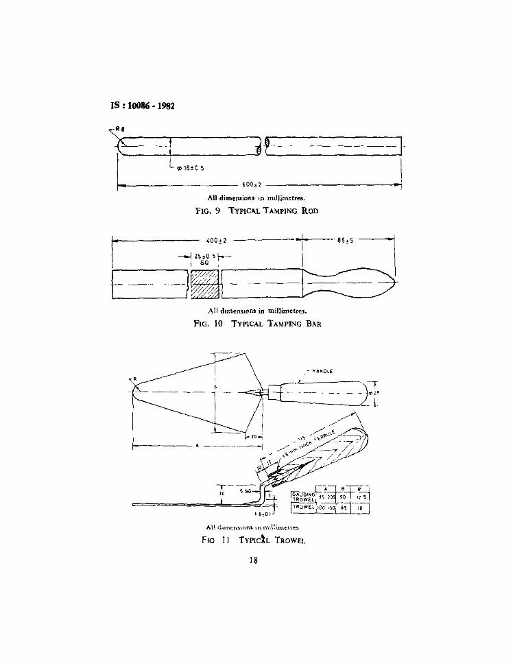
6.1 Tamping Rod - The tamping rod shall be of the followmg types:a) 16 ± 0'5 mm dia and 600 ± 2 mm long with a rounded working
end shall be made of mild steel ( see Fig. 9 ),b) Of square section with tamping face 25 ± 0'5 mm square and
400 ± 2 mm long and weighing 2 kg shall be made of mildsteel and provided with a handle (see FIg 10).
C) Of 12X 25 mm cross-section and convenient length of125 to 150 mm; tamping face shall be flat and at fight angles to thelength of the bar, shall be made of non-absorbent, abr asior,resistant non-brittle material, such as a rubber compound having aShore A Durometer hardness of 80 ± 10 or seasoned teak woodrendered non-absorbent by Immersion for 15 mill III paraffinat approximately 200°C. or ebornte fibre
6.2 Gauging Trowel- The gauguig trowel shall be made of mild steeland shall be in accordance with FIg I I. The trowel blade shall be ofmmimum thickness ]'5 mm and of length 195 mm and shall be providedWIth a wooden handle. The trowel shall weigh 210 ± 10 g
6.3 Trowel- The trowel shall be made of mild steel and shall be 1Il
accordance with Fig. I I. The trowel blade shall be of nunimum thickness1'5 mm and 100 to 150 mm length with straight edges
7. MARKING
7.1 The following mforrnation shall be clearly and mdehbly marked on eachcomponent of the mould as far as practicable III way that it does notinterfere with the performance of the mould.
a) Name of the manufacturer or his registered trade mark orboth, and
b) Date of manufacture.
7.1.1 fhe product may also be marked With Standard Mark
1.1.2 The u;e of the Standard Mark IS governed by the provisions ofthe Bureauof Indian Standards Act. 1986 and the Rule' and Regulations made thereunderI he details of condmons under which the licence for the use of Standard Markmay be granted to manufactures or producers may be obtamed from the Bureauof Indian Standards
17
IS : 10086 • 1982
F[
--ILCP16±05
i~-- ------ ---+I
-IAll dimensions In rmllimetres.
rf--
FIG. 9 TYPICAL TAMPING ROD
All drmensrcna in millimetres,
FIG. 10 TYPICAL TAMPING BAR
- HANDLE
----I Ii
/ iJ-_-=::>{~ 20 ..,
>------- • -----------I
T---- ,)0 S sc
=========b="""~,,~
-. --E
--.~UGiNG'+-."', '-1J+"-\-
1ROWel '
HlOWEl ICO ISO
FIG II TYPICh TROWEl.
18

IS : 10086 • 1981
( Continued from pagl 2 )
Instruments for Cement and Concrete Testing Subcommittee, DOC 2 : 10
( India)
(CSIR :.
(CSIR), New
InstituteResearch
Research Institute
Public Works Department, Government of UttarPradesh, Ludmow
The Associated Cement Cornpames Ltd. Bombay
RefJresmltng
Engmcering Research Laboratories, Hvderabad
AssoCIated Instrument ManufacturersPrivate Ltd, New De lhr
CLmf"nt Research lnsu tute of India, New Delhi
Central BurldmgRoorkee
Research & Development Orgamaauon (MInistry orDefence), Pune
Indian Inautute of Technology. New DeihlHighways Research Station, MadrasAll l ndra Instruments Manufacturers and Dealers
Assoctanon, Bombay
( Alumate )L:entral Road
Deihl
SHRI SUDI-IASH SHARMA
SURf K. L SETHI
SHRI J P. KAUSHI9H (Alternate)
SHRI A. v S R. SA6TRI
CORVen"
DR IQBAL ALI
Member!SHAI P. D. AOARWAL
SHRI Y. P. PATHAK (Alternate)SHRI E. K RAMACHANDRAN National Test Houle, Calcutta
SHRIS. K BANERJEr. (Altunate )PROF C K. RAMESH Indra-i Insutute of Technology, Bombay
VR R S. Ayyar (AlI.rnMe)SARI 1\1. V RANGA RAO
DR K C NARAtoiG (Alternate)DR S. S. REHSI
DR T. N CHOjER ( Altemau )
PROF B. 1\1 AHUJA
SHRJT.P.EKAMBARAM
SHRI H K. GUHA
DEPUTY SECRET....av (AI/emaIl')
SMR. P J ] AGUSSHRI D AWADIA ( Alt~nate)
SHRl M. R. JOSHI
5HRl M L BHA"IIA (Alternate)
19
BUREAU OF INDIAN STANDARDSHeadquartersManak Bhavan 9 Bahadur Shah Zatar Marg, NEW DELHI 110002Telephones 23230131,2323337523239402 Fax 91+01123239399,23239382E· Mail bls@vsnlcom website httpllwwwblscrgln
Central Laboratory:
Plot No 2019, Site IV, Sarnbabad Industrral Area, SAHIBABAD 201010
Regional Offices:Central Manak Bhavan, 9 Bahadur Shah Zatar Marg, NEW DELHI 110002
'Easlern 1/14 CIT Scheme VII M, V I P Road, Kankurgachl, KOlKATA 700054
Northern SCO 335·338, Sector 34-A, CHANDIGARH 160022
Southern CIT Campus, IV Cross Road, CHENNAI 600113
Western Manakalaya, E9, MIDC, Behind MarolTelephone Exchange,Andherr (East), MUMBAI 400093
Branch Offices:'Pushpak', Nurmohamed ShaIkh Marg, Khanpur, AHMEDABAD 3BOOOIPeonya Industrral Area, I" Stage, Bangalore-Tumkur Road, BANGALORE
Commerciat-curn-Otnce Complex, Opp Dushera Maiden, E·5 Arera Colony,Bittan Market, BHOPAL 462016
62-63, Ganga Na9ar, Unit VI, BHUBANESHWAR 751001
5'" Floor, Koval Towers, 44 Bala Sundaram Road, COIMBATORE 641018
SCO 21, Sector 12, Farrdabad 121007
Savrtrr Complex, 116 G T Road, GHAZIABAD 201001
Piol No A·20·21, Institutional Area, Sector 62, Goutam Budh Nagar, NOIDA-201307
53/5 Ward No 29, R G Barua Road, 5th By-lane, Apurba Sinha Path,GUWAHATI781003
5·B-56C, l N Gupta Marg, Nampally StallOn Road, HYDERABAD 500001E-52, Ctutararuan Marg, c-Screme. JAIPUR 302001
1171418 B, Sarvodaya Nagar, KANPUR 208005
SethiBhawan, 2n(j Floor, Behind Leela Cinema, Naval Kishore Road,LUCKNOW 226001
NIT BUilding, Second Floor, Gokulpat Market, NAG PUR 440010
MahabrrBhavan, I" Floor, Hepar Road, NALAGARH 174101
Patllputra Industrral Estate, PATNA 800013
Frrsl Floor, Plot Nos 657 ·660, Market Yard, Gultkdl, PUNE 411037
"Sahaianand House" 3" Floor, Bhakllnagar Circle, 80 Feel Road,RAJKOT 360002
T C No 14/1421, UniversIty PO Palayam, THIRUVANANTHAPURAM 695034
I" Floor, Udyog Bhavan, VUDA, Smpuram Junction, VISHAKHAPATNAM·03
Sales Office 's at 5 Chownnghee Approach, PO Pnncep Street, KOlKATA 700072
Sates Office IS at Novelty Chambers, Grant Road, MUMBAI 400007
Telephone
2770032
23237617
23376662
260 38 43
22541984
28329295
5601346
8394955
24234 52
24031 39221 01 41
22921 75
2861498
2402206
2541137
232010842373879
22t 8292
22t 5698
25251 71
221451
2262808
4268659
2378251
23221 04
2712833
22126215
23096528
Printed at Simco Pnnllng Press, DelhI