Embed Size (px)
Citation preview

8/12/2019 Is 1239 Book
http://slidepdf.com/reader/full/is-1239-book 1/34
Disclosure to Promote the Right To Information
Whereas the Parliament of India has set out to provide a practical regime of right to
information for citizens to secure access to information under the control of public authorities,in order to promote transparency and accountability in the working of every public authority,
and whereas the attached publication of the Bureau of Indian Standards is of particular interest
to the public, particularly disadvantaged communities and those engaged in the pursuit of
education and knowledge, the attached public safety standard is made available to promote the
timely dissemination of this information in an accurate manner to the public.
!"#$%&# '(%)
“ !"# $ %& #' (")* &" +#,-. ”Satyanarayan Gangaram Pitroda
“Invent a New India Using Knowledge”
“ /0 )"1 &2 324 #' 5 *)6 ” Jawaharlal Nehru
“Step Out From the Old to the New”
“ 7"#1 &" 8+9&") , 7:1 &" 8+9&") ”Mazdoor Kisan Shakti Sangathan
“The Right to Information, The Right to Live”
“ !"# %& ;<" =7"#" > 72 &(: ?0 )"@" #AB 7" <&*" A *”Bhart+hari—N,ti-atakam
“Knowledge is such a treasure which cannot be stolen”
IS 1239-2 (2011): Steel Tubes, Tubulars and Other Steel
Fittings, Part 2: Steel Pipe Fittings [MTD 19: Steel Tubes,
Pipes abd Fittings]

8/12/2019 Is 1239 Book
http://slidepdf.com/reader/full/is-1239-book 2/34
8/12/2019 Is 1239 Book
http://slidepdf.com/reader/full/is-1239-book 3/34
8/12/2019 Is 1239 Book
http://slidepdf.com/reader/full/is-1239-book 4/34
© BIS 2011
B U R E A U O F I N D I A N S T A N D A R D SMANAK BHAVAN, 9 BAHADUR SHAH ZAFAR MARG
NEW DELHI 110002
September 2011 Price Group 10
IS 1239 (Part 2) : 2011
Hkkjrh; ekud
bLikr dh ufy;k¡] ufydkdkj lkefxz;k¡ rFkk bLikr dh
vU; fQfVaxsa — fof'kf"VHkkx 2 bLikr dh ikbZi fQfVaxsa
( ik¡pok iqujh{k.k )
Indian Standard
STEEL TUBES, TUBULARS AND OTHER STEEL
FITTINGS — SPECIFICATION
PART 2 STEEL PIPE FITTINGS
( Fifth Revision )
ICS 77.140.75
8/12/2019 Is 1239 Book
http://slidepdf.com/reader/full/is-1239-book 5/34
Steel Tubes, Pipes and Fittings Sectional Committee, MTD 19
FOREWORD
This Indian Standard (Part 2) (Fifth Revision) was adopted by the Bureau of Indian Standards, after the draft
finalized by the Steel Tubes, Pipes and Fittings Sectional Committee had been approved by the Metallurgical
Engineering Division Council.
This standard was first published in 1969 and fourth revision of this standard was published in 1992. While
reviewing this standard in the light of experience gained during these years, the Committee decided to further
revise this standard.
In this revision the following modifications have been made:
a) All amendments (Amendment Nos. 1 to 6) have been incorporated.
b) The requirement of approximate radius for 125 and 150 NB bends have been incorporated in Table 4.
c) Additional column for maximum inside diameter of internal parallel thread for steel socket have beenincorporated in Table 6.
This standard is published in two parts. The other part in the series is:
Part 1 Steel tubes
The nominal bores specified in this standard and the corresponding nominal sizes of pipe threads according to
IS 554 : 1999/ISO 7-1 : 1994 ‘Pipe thread where pressure tight joints are made on the threads — Dimension,
tolerance and designation ( fourth revision)’ are given in Annex A.
The standard keeps in view the manufacturing and trade practices followed in the country in this field. In formulating
this standard assistance has been derived from the following publications:
BS 1387 : 1967 ‘Specification for steel tubes and tubulars (suitable for screwing to B. S. 21 pipe
threads)’, issued by the British Standards Institution (BSI).
BS 1740 : 1965 ‘Specification for wrought pipe fitting, iron and steel (screwed B. S. P. thread)’,
issued by the British Standards Institution (BSI ).
For the purpose of deciding whether a particular requirement of this standard is complied with, the final value,
observed or calculated, expressing the result of a test or analysis, shall be rounded off in accordance with IS 2 : 1960
‘Rules for rounding off numerical values (revised )’. The number of significant places retained in the rounded off
value should be same as that of the specified value in this standard.

8/12/2019 Is 1239 Book
http://slidepdf.com/reader/full/is-1239-book 6/34
8/12/2019 Is 1239 Book
http://slidepdf.com/reader/full/is-1239-book 7/34
1
IS 1239 (Part 2) : 2011
Indian Standard
STEEL TUBES, TUBULARS AND OTHER STEEL
FITTINGS — SPECIFICATION
PART 2 STEEL PIPE FITTINGS
( Fifth Revision )
1 SCOPE
This standard (Part 2) covers the requirements for butt
welded and seamless, plain ended, screwed sockets,
steel tubulars and other welded and seamless steel pipe
fittings intended for use for water, non-hazardous gas,
air and steam. The requirements of pipe nuts are
covered in IS 3468.
2 REFERRENCES
The following standards contain provisions which,
through reference in this text, constitute provisions of
this standard. At the time of publication, the editions
indicated were valid. All standards are subject to
revision and parties to agreements based on this
standard are encouraged to investigate the possibility
of applying the most recent editions of the standards
indicated below:
IS No. Title
228 (All parts) Methods of chemical analysis of
steels
554 : 1999/ Pipe threads where pressure-tight
ISO 7-1 : 1994 joints are made on the threads—
Dimension, tolerances and
designation ( fourth revision)
1239 (Part 1) : Steel tubes, tubulars and other
2004 wrought steel fittings — Specification :
Part 1 Steel tubes (sixth revision)
1387 : 1993 General requirements for the supply
of metallurgical materials (second
revision)
1501 : 2002/ Method for Vickers hardness test for
ISO 6507-1 : metallic materials (third revision)
1997
1608 : 2005/ Metallic materials — Tensile testing
ISO 6892 : 1998 at ambient temperature (third revision)
1879 : 1987 Malleable cas t iron pipe fi ttings
(second revision)
2335 : 2005/ Metallic materials — Tube drift
ISO 8493 : expanding test (second revision)
1998
2629 : 1985 Recommended practice for hot-dip
galvanizing of iron and steel ( first
revision)
IS No. Title
2633 : 1986 Methods for testing uniformity of
coating on zinc coated articles
(second revision)
3468 : 1991 Pipe nuts (second revision)
4711 : 2008 Methods for sampling of steel pipes,
tubes and fittings (second revision)
4736 : 1986 Speci fi ca ti on fo r ho t di p zi nc
coatings on mild steel tubes ( first revision)
8999 : 2003/ Pipe threads where pressure-tight
ISO 7-2 : 2000 joints are made on the threads —
Verification by means of limit gauges
( first revision)
3 TERMINOLOGY
For the purpose of this standard, the following
definitions shall apply.
3.1 Fittings — Term used to denote fittings like elbows,
tee, cross, etc.
3.2 Socket — The screwed coupling utilized in jointingthe tubes together.
NOTE — The term socket is synonymous with the term
coupling, barrel and column socket.
3.3 Tube (Pipe) — A long, hollow, open-ended object
circular or other cross-section. The terms tube and pipe
are often used synonymously.
3.4 Tubular — A term used to include pieces, long-
screws, bends springs, return bends and barrel nipples.
4 DESIGNATION
4.1 Steel sockets and tubular covered by this standard
shall be designated by their nominal bore.
4.2 Other steel fittings shall be designated giving the
following particulars in the sequence shown:
a) Type of fittings (see 4.2.1); and
b) Size designation (see 4.2.2).
4.2.1 Type of Fittings
The types of fittings are denoted as elbow, tee, cross,
etc.
8/12/2019 Is 1239 Book
http://slidepdf.com/reader/full/is-1239-book 8/34
2
IS 1239 (Part 2) : 2011
4.2.2 Size Designation
This is determined by the nominal bore, in millimetre
of the pipe at the outlets.
4.2.2.1 Equal fitting
Where all outlets in a given fitting are of the same size,
the fitting shall be referred to by that one size,
irrespective of the number of the outlets.
4.2.2.2 Unequal fittings
These are referred to by the size of each outlet.
5 SUPPLY OF MATERIAL
General requirements relating to the supply of steel
tubulars and other fittings shall conform to IS 1387.
6 MANUFACTURE
6.1 Tubulars conforming to this standard shall be made
from tubes which comply with all the appropriate
requirements of IS 1239 (Part 1).
6.2 Sockets
Sockets shall be manufactured from mild steel by any
of the following processes:
a) Hot-finished seamless (HFS);
b) Electric resistance welded or high frequency
induction welded ERW or HFIW;
c) Hot-finished welded (HFW); and
d) Hand welded.
6.2.1 All sockets shall be either welded or seamless as
agreed to between the purchaser and the manufacturer.6.2.2 All electrically welded sockets used for steam
services shall be normalized.
6.3 Other Fittings
Other steel pipe fittings excluding socket shall be
manufactured from steel by any approved process.
6.3.1 Unless otherwise specified by the purchaser, all
fittings shall be manufactured with thread connections,
complying with the requirements of IS 554. At the
request of the purchaser, the manufacturer is permitted
to make plain end fittings without screwing as per the
dimensions given in the relevant tables. The outsidediameter of the plain end fittings match with the outside
diameter of tubes in accordance with IS 1239 (Part 1).
Outside diameter of the internal threaded fittings shall
be same as outside diameter of sockets as per Table 6.
6.4 The steel from which the fittings are made, when
tested in accordance with IS 1608 shall show on test a
minimum tensile strength of 320 MPa. The percentage
elongation on a gauge length of 5.65 oS (where S o
is the original cross-section of the test specimen) shall
not be less than 20 percent.
7 CHEMICAL COMPOSITION
7.1 The ladle analysis of steel shall not show sulphur
and phosphorus in amounts exceeding 0.05 percent
each.
7.1.1 The ladle analysis of steel shall be carried out
either by the method specified in IS 228 or any other
established instrumented/chemical method. In case of
dispute the procedure given in IS 228 and its relevant
parts shall be referee method.
However, where the method is not given in IS 228 and
its relevant parts, the referee method shall be as agreed
to between the purchaser and the manufacturer.
7.1.2 Product Analysis
The maximum permissible variation of sulphur and
phosphorus, in case of product analysis from the limits
specified under 7.1 shall be 0.005 percent each.
NOTE — The product analysis is not applicable to rimming
quality steel.
8 DIMENSIONS OF TUBULARS
8.1 Pieces
Pieces shall conform to the dimensions given in
Table 1.
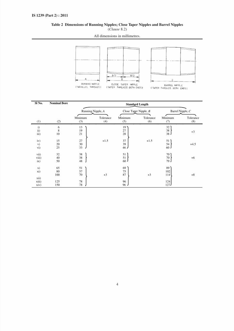
8.2 Nipples
Close taper and running nipples shall be made only
from heavy tubes. Barrel nipples shall be made eitherfrom medium or heavy tubes. The dimensions of
nipples shall be as given in Table 2.
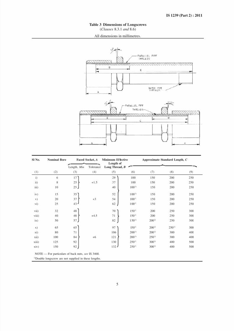
8.3 Longscrews (Connectors)
8.3.1 Longscrews (connectors) shall be made only from
heavy tube and shall be supplied single or double, as
may be specified, and shall conform to the appropriate
dimensions given in Table 3.
8.3.2 The sockets shall be suitably faced on the end
which the back nut abuts. The face of the back nut
which abuts against the sockets shall be concave at an
angle of approximately 15°.
8.3.3 The parallel threads on the longscrew and in the
socket shall, in addition to complying with the
appropriate requirement of IS 554, be of such a size
that the socket runs on the connector hand-tight without
perceptible shake.
This type of joints is permissible for low pressures,
but is not recommended for higher pressures or for
work in which there are wide variations of temperature.
8/12/2019 Is 1239 Book
http://slidepdf.com/reader/full/is-1239-book 9/34
3
IS 1239 (Part 2) : 2011
NOTE — When it is necessary to use longscrew for running
joints, the threads of the longscrew which accommodates, the
running socket and back nut shall be parallel.
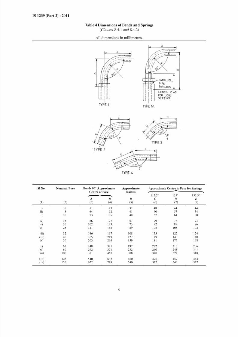
8.4 Bends and Springs
8.4.1 Bends and springs shall conform to the
approximate dimensions given in Table 4. A tolerance
of ±1.5° on the specified angle shall be permitted.
8.4.2 Type 1A bends shall be made only from heavy
tubes and in addition to conforming to the approximate
dimensions given in Table 4, shall be fitted with sockets
and back nuts conforming to the requirements given
in 8.3.2.
8.4.3 Each bend and spring shall be supplied with one
socket, if so specified by the purchaser.
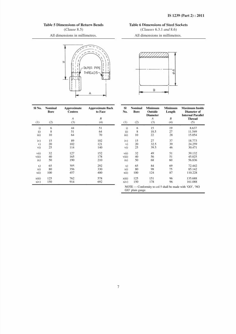
8.5 Return Bends
Return bends shall be made from heavy tube, supplied
with socket at one end if so specified by the purchaser,
and shall conform to the dimensions given in Table 5.The ends of the bends shall be parallel within ±1.5°.
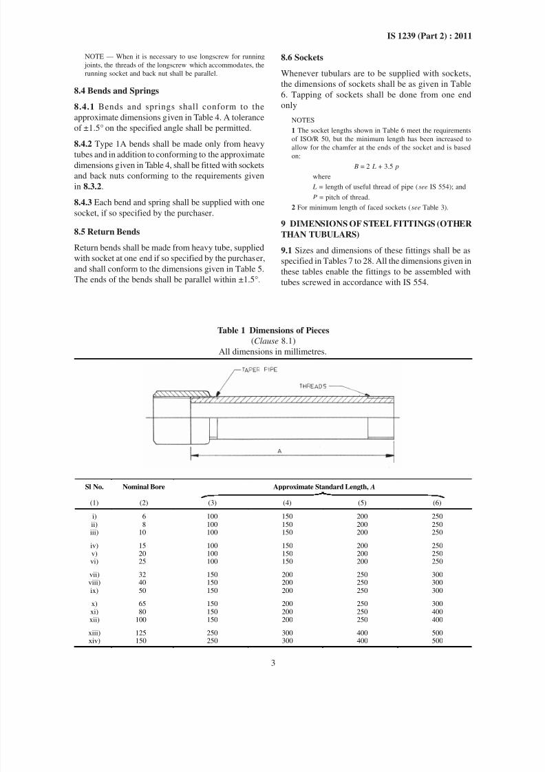
Table 1 Dimensions of Pieces
(Clause 8.1)
All dimensions in millimetres.
Sl No. Nominal Bore Approximate Standard Length, A
(1) (2) (3) (4) (5) (6)
i) 6 100 150 200 250ii) 8 100 150 200 250iii) 10 100 150 200 250
iv) 15 100 150 200 250v) 20 100 150 200 250vi) 25 100 150 200 250
vii) 32 150 200 250 300viii) 40 150 200 250 300ix) 50 150 200 250 300
x) 65 150 200 250 300xi) 80 150 200 250 400xii) 100 150 200 250 400
xiii) 125 250 300 400 500xiv) 150 250 300 400 500
8.6 Sockets
Whenever tubulars are to be supplied with sockets,
the dimensions of sockets shall be as given in Table
6. Tapping of sockets shall be done from one end
only
NOTES
1 The socket lengths shown in Table 6 meet the requirements
of ISO/R 50, but the minimum length has been increased to
allow for the chamfer at the ends of the socket and is based
on:
B = 2 L + 3.5 p
where
L = length of useful thread of pipe (see IS 554); and
P = pitch of thread.
2 For minimum length of faced sockets (see Table 3).
9 DIMENSIONS OF STEEL FITTINGS (OTHER
THAN TUBULARS)
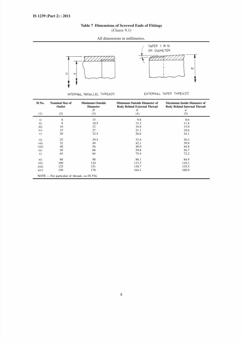
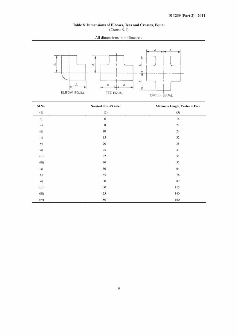
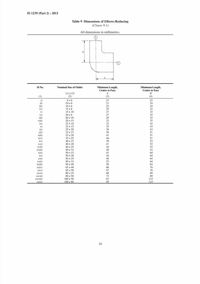
9.1 Sizes and dimensions of these fittings shall be as
specified in Tables 7 to 28. All the dimensions given in
these tables enable the fittings to be assembled withtubes screwed in accordance with IS 554.
8/12/2019 Is 1239 Book
http://slidepdf.com/reader/full/is-1239-book 10/34
4
IS 1239 (Part 2) : 2011
Table 2 Dimensions of Running Nipples; Close Taper Nipples and Barrel Nipples
(Clause 8.2)
All dimensions in millimetres.
Sl No. Nominal Bore Standard Length
Running Nipple, A Close Taper Nipple, B Barrel Nipple,C
Minimum Tolerance Minimum Tolerance Minimum Tolerance(1) (2) (3) (4) (5) (6) (7) (8)
i) 6 13 19 32ii) 8 19 27 38iii) 10 21 28 38
+3
iv) 15 27 37 51v) 20 30 39 54vi) 25 33
+1.5
46
+1.5
60+4.5
vii) 32 38 51 70viii) 40 38 51 70ix) 50 48 60 79
+6
x) 65 51 69 89xi) 80 57 75 102
100 70 87 114xii)xiii) 125 78 96 124xiv) 150 78
+3
96
+3
127
+8
8/12/2019 Is 1239 Book
http://slidepdf.com/reader/full/is-1239-book 11/34
8/12/2019 Is 1239 Book
http://slidepdf.com/reader/full/is-1239-book 12/34
6
IS 1239 (Part 2) : 2011
Table 4 Dimensions of Bends and Springs
(Clauses 8.4.1 and 8.4.2)
All dimensions in millimetres.
Sl No. Nominal Bore Bends 90° Approximate
Centre of Face
Approximate
Radius
Approximate Centre to Face for Springs
112.5°
135°
157.5°
A B R C D E(1) (2) (3) (4) (5) (6) (7) (8)
i) 6 51 73 32 48 44 44ii) 8 64 92 41 60 57 54
iii) 10 73 105 48 67 64 60
iv) 15 86 127 57 79 76 73v) 20 102 143 73 92 89 86vi) 25 121 168 89 108 105 102
vii) 32 146 197 108 133 127 124
viii) 40 165 219 127 149 143 140ix) 50 203 264 159 181 175 168
x) 65 248 321 197 222 213 206xi) 80 292 371 232 260 248 241xii) 100 381 467 308 340 324 318
xiii) 125 540 632 460 476 457 444xiv) 150 622 718 540 572 540 527
8/12/2019 Is 1239 Book
http://slidepdf.com/reader/full/is-1239-book 13/34
7
IS 1239 (Part 2) : 2011
Table 5 Dimensions of Return Bends Table 6 Dimensions of Steel Sockets
(Clause 8.5) (Clauses 6.3.1 and 8.6)
All dimensions in millimetres. All dimensions in millimetres.
Sl No. Nominal
Bore
Approximate
Centres
Approximate Back
to Face
Sl
No.
Nominal
Bore
Minimum
OutsideDiameter
Minimum
Length
A B A B
Maximum Inside
Diameter ofInternal Parallel
Thread(1) (2) (3) (4) (1) (2) (3) (4) (5)
i) 6 44 51 i) 6 15 19 8.637ii) 8 51 64 ii) 8 18.5 27 11.549
iii) 10 64 70 iii) 10 22 28 15.054
iv) 15 89 102 iv) 15 27 37 18.773v) 20 102 121 v) 20 32.5 39 24.259
vi) 25 114 140 vi) 25 39.5 46 30.471
vii) 32 127 152 vii) 32 49 51 39.132viii) 40 165 178 viii) 40 56 51 45.025
ix) 50 190 210 ix) 50 68 60 56.836
x) 65 305 292 x) 65 84 69 72.442xi) 80 356 330 xi) 80 98 75 85.142
xii) 100 457 400 xii) 100 124 87 110.228
xiii) 125 762 578 xiii) 125 151 96 135.688xiv) 150 914 692 xiv) 150 178 96 161.088
NOTE — Conformity to col 5 shall be made with ‘GO’, ‘NOGO’ plain gauge.
8/12/2019 Is 1239 Book
http://slidepdf.com/reader/full/is-1239-book 14/34
8
IS 1239 (Part 2) : 2011
Table 7 Dimensions of Screwed Ends of Fittings
(Clause 9.1)
All dimensions in millimetres.
Sl No. Nominal Size of
Outlet
Minimum Outside
Diameter
Minimum Outside Diameter of
Body Behind External Thread
Maximum Inside Diameter of
Body Behind Internal Thread D E d
(1) (2) (3) (4) (5)
i) 6 15 9.8 8.6ii) 8 18.5 13.3 11.4iii) 10 22 16.8 15.0iv) 15 27 21.1 18.6v) 20 32.5 26.6 24.1
vi) 25 39.5 33.4 30.3vii) 32 49 42.1 39.0viii) 40 56 48.0 44.8
ix) 50 68 59.8 56.7x) 65 84 75.4 72.2
xi) 80 98 88.1 84.9xii) 100 124 113.3 110.1xiii) 125 151 138.7 135.5
xiv) 150 178 164.1 160.9
NOTE — For particular of threads, see IS 554 .
8/12/2019 Is 1239 Book
http://slidepdf.com/reader/full/is-1239-book 15/34
9
IS 1239 (Part 2) : 2011
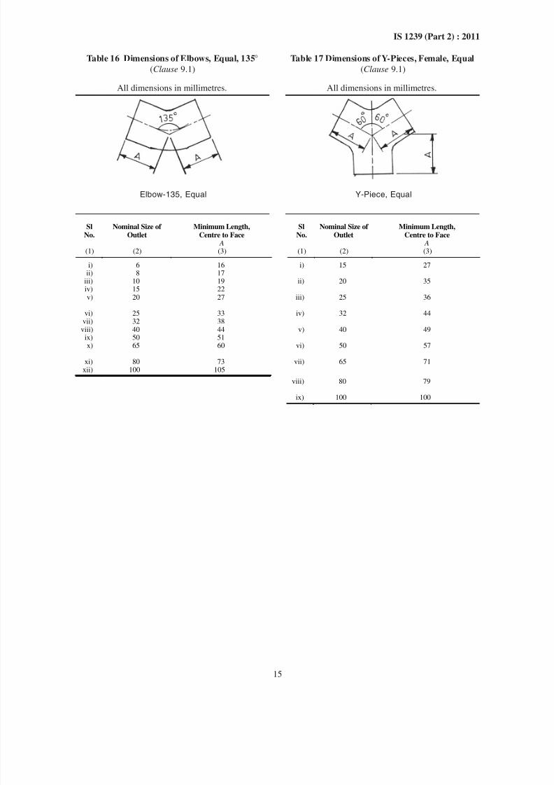
Table 8 Dimensions of Elbows, Tees and Crosses, Equal
(Clause 9.1)
All dimensions in millimetres.
Sl No. Nominal Size of Outlet Minimum Length, Centre to Face
(1) (2) (3)
i) 6 16
ii) 8 22
iii) 10 24
iv) 15 32
v) 20 35
vi) 25 43
vii) 32 51
viii) 40 52
ix) 50 64
x) 65 76
xi) 80 89
xii) 100 115
xiii) 125 140
xiv) 150 160
8/12/2019 Is 1239 Book
http://slidepdf.com/reader/full/is-1239-book 16/34
10
IS 1239 (Part 2) : 2011
Table 9 Dimensions of Elbows Reducing
(Clause 9.1)
All dimensions in millimetres.
Sl No. Nominal Size of Outlet Minimum Length,
Centre to Face
Minimum Length,
Centre to Face(1) × (2) A B
(1) (2) (3) (4)
i) 8 × 6 21 22ii) 10 × 6 21 24
iii) 10 × 8 22 24iv) 15 × 8 25 32v) 15 × 10 27 32
vi) 20 × 8 27 35vii) 20 × 10 29 35
viii) 20 × 15 32 35ix) 25 × 10 32 43x) 25 × 15 35 43
xi) 25 × 20 38 43xii) 32 × 15 38 51
xiii) 32 × 20 41 51xiv) 32 × 25 44 51xv) 40 × 15 38 52
xvi) 40 × 20 41 52xvii) 40 × 25 44 52
xviii) 40 × 32 48 52xix) 50 × 15 41 64xx) 50 × 20 44 64
xxi) 50 × 25 48 64xxii) 50 × 32 52 64
xxiii) 50 × 40 56 64xxiv) 65 × 40 60 76xxv) 65 × 50 67 76
xxvi) 80 × 25 60 89xxvii) 80 × 50 73 89
xxviii) 100 × 50 83 115xxix) 100 × 80 95 115
8/12/2019 Is 1239 Book
http://slidepdf.com/reader/full/is-1239-book 17/34
11
IS 1239 (Part 2) : 2011
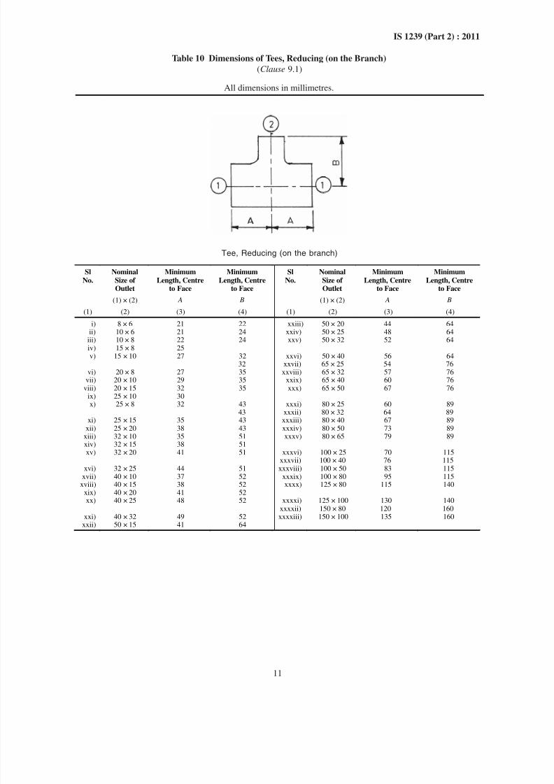
Table 10 Dimensions of Tees, Reducing (on the Branch)
(Clause 9.1)
All dimensions in millimetres.
Tee, Reducing (on the branch)
SlNo. NominalSize ofOutlet
MinimumLength, Centreto Face
MinimumLength, Centreto Face
SlNo. NominalSize ofOutlet
MinimumLength, Centreto Face
MinimumLength, Centreto Face
(1) × (2) A B (1) × (2) A B
(1) (2) (3) (4) (1) (2) (3) (4)
i) 8 × 6 21 22 xxiii) 50 × 20 44 64ii) 10 × 6 21 24 xxiv) 50 × 25 48 64iii) 10 × 8 22 24 xxv) 50 × 32 52 64iv) 15 × 8 25v) 15 × 10 27 32 xxvi) 50 × 40 56 64
32 xxvii) 65 × 25 54 76vi) 20 × 8 27 35 xxviii) 65 × 32 57 76
vii) 20 × 10 29 35 xxix) 65 × 40 60 76viii) 20 × 15 32 35 xxx) 65 × 50 67 76
ix) 25 × 10 30x) 25 × 8 32 43 xxxi) 80 × 25 60 89
43 xxxii) 80 × 32 64 89xi) 25 × 15 35 43 xxxiii) 80 × 40 67 89
xii) 25 × 20 38 43 xxxiv) 80 × 50 73 89xiii) 32 × 10 35 51 xxxv) 80 × 65 79 89xiv) 32 × 15 38 51xv) 32 × 20 41 51 xxxvi) 100 × 25 70 115
xxxvii) 100 × 40 76 115xvi) 32 × 25 44 51 xxxviii) 100 × 50 83 115
xvii) 40 × 10 37 52 xxxix) 100 × 80 95 115xviii) 40 × 15 38 52 xxxx) 125 × 80 115 140
xix) 40 × 20 41 52xx) 40 × 25 48 52 xxxxi) 125 × 100 130 140
xxxxii) 150 × 80 120 160xxi) 40 × 32 49 52 xxxxiii) 150 × 100 135 160
xxii) 50 × 15 41 64
8/12/2019 Is 1239 Book
http://slidepdf.com/reader/full/is-1239-book 18/34
12
IS 1239 (Part 2) : 2011
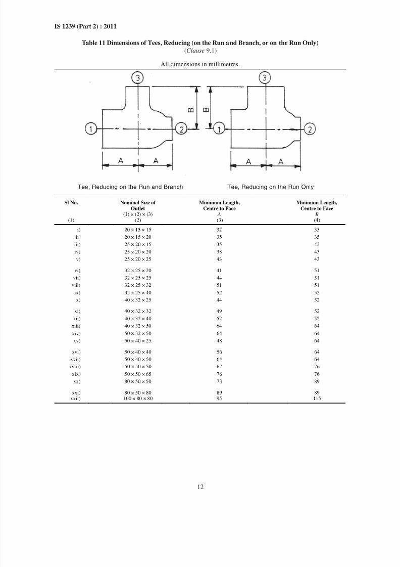
Table 11 Dimensions of Tees, Reducing (on the Run and Branch, or on the Run Only)
(Clause 9.1)
All dimensions in millimetres.
Tee, Reducing on the Run and Branch Tee, Reducing on the Run Only
Sl No. Nominal Size of
Outlet
Minimum Length,
Centre to Face
Minimum Length,
Centre to Face(1) × (2) × (3) A B
(1) (2) (3) (4)
i) 20 × 15 × 15 32 35
ii) 20 × 15 × 20 35 35
iii) 25 × 20 × 15 35 43
iv) 25 × 20 × 20 38 43
v) 25 × 20 × 25 43 43
vi) 32 × 25 × 20 41 51
vii) 32 × 25 × 25 44 51
viii) 32 × 25 × 32 51 51
ix) 32 × 25 × 40 52 52
x) 40 × 32 × 25 44 52
xi) 40 × 32 × 32 49 52
xii) 40 × 32 × 40 52 52
xiii) 40 × 32 × 50 64 64
xiv) 50 × 32 × 50 64 64
xv) 50 × 40 × 25 48 64
xvi) 50 × 40 × 40 56 64
xvii) 50 × 40 × 50 64 64
xviii) 50 × 50 × 50 67 76
xix) 50 × 50 × 65 76 76
xx) 80 × 50 × 50 73 89
xxi) 80 × 50 × 80 89 89
xxii) 100 × 80 × 80 95 115
8/12/2019 Is 1239 Book
http://slidepdf.com/reader/full/is-1239-book 19/34
13
IS 1239 (Part 2) : 2011
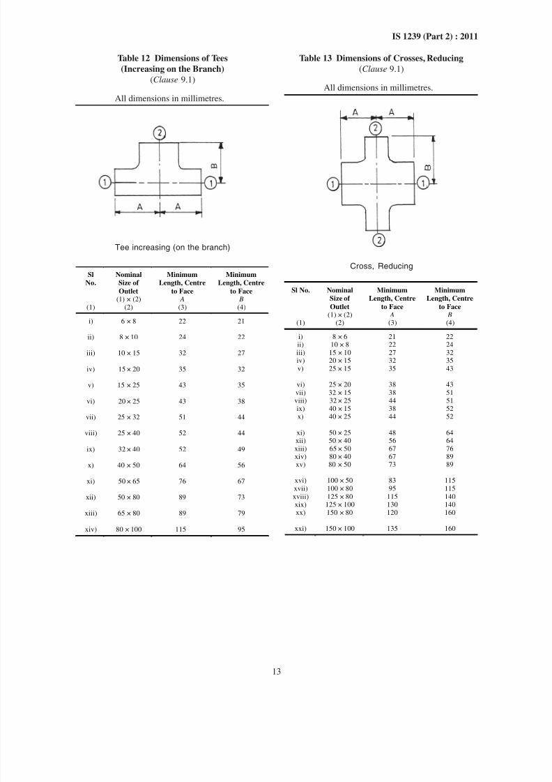
Table 12 Dimensions of Tees
(Increasing on the Branch)
(Clause 9.1)
All dimensions in millimetres.
Tee increasing (on the branch)
SlNo.
NominalSize of
Outlet
MinimumLength, Centre
to Face
MinimumLength, Centre
to Face(1) × (2) A B
(1) (2) (3) (4)
i) 6 × 8 22 21
ii) 8 × 10 24 22
iii) 10 × 15 32 27
iv) 15 × 20 35 32
v) 15 × 25 43 35
vi) 20 × 25 43 38
vii) 25 × 32 51 44
viii) 25 × 40 52 44
ix) 32 × 40 52 49
x) 40 × 50 64 56
xi) 50 × 65 76 67
xii) 50 × 80 89 73
xiii) 65 × 80 89 79
xiv) 80 × 100 115 95
Table 13 Dimensions of Crosses, Reducing
(Clause 9.1)
All dimensions in millimetres.
Cross, Reducing
Sl No. Nominal
Size of
Outlet
Minimum
Length, Centre
to Face
Minimum
Length, Centre
to Face(1) × (2) A B
(1) (2) (3) (4)
i) 8 × 6 21 22ii) 10 × 8 22 24iii) 15 × 10 27 32iv) 20 × 15 32 35v) 25 × 15 35 43
vi) 25 × 20 38 43
vii) 32 × 15 38 51viii) 32 × 25 44 51
ix) 40 × 15 38 52x) 40 × 25 44 52
xi) 50 × 25 48 64xii) 50 × 40 56 64xiii) 65 × 50 67 76xiv) 80 × 40 67 89xv) 80 × 50 73 89
xvi) 100 × 50 83 115xvii) 100 × 80 95 115
xviii) 125 × 80 115 140xix) 125 × 100 130 140xx) 150 × 80 120 160
xxi) 150 × 100 135 160
8/12/2019 Is 1239 Book
http://slidepdf.com/reader/full/is-1239-book 20/34
14
IS 1239 (Part 2) : 2011
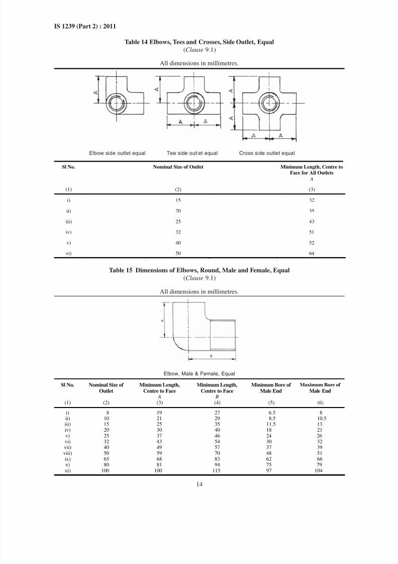
Table 14 Elbows, Tees and Crosses, Side Outlet, Equal
(Clause 9.1)
All dimensions in millimetres.
Elbow side outlet equal Tee side outlet equal Cross side outlet equal
Sl No. Nominal Size of Outlet Minimum Length, Centre to
Face for All Outlets
A
(1) (2) (3)
i) 15 32
ii) 20 35
iii) 25 43
iv) 32 51
v) 40 52
vi) 50 64
Table 15 Dimensions of Elbows, Round, Male and Female, Equal
(Clause 9.1)
All dimensions in millimetres.
Elbow, Male & Female, Equal
Sl No. Nominal Size of
Outlet
Minimum Length,
Centre to Face
Minimum Length,
Centre to Face
Minimum Bore of
Male End
Maximum Bore of
Male End
A B(1) (2) (3) (4) (5) (6)
i) 8 19 27 6.5 8ii) 10 21 29 8.5 10.5iii) 15 25 35 11.5 13iv) 20 30 40 18 21v) 25 37 46 24 26vi) 32 43 54 30 32vii) 40 49 57 37 39viii) 50 59 70 48 51ix) 65 68 83 62 66x) 80 81 94 75 79xi) 100 100 115 97 104
8/12/2019 Is 1239 Book
http://slidepdf.com/reader/full/is-1239-book 21/34
8/12/2019 Is 1239 Book
http://slidepdf.com/reader/full/is-1239-book 22/34
16
IS 1239 (Part 2) : 2011
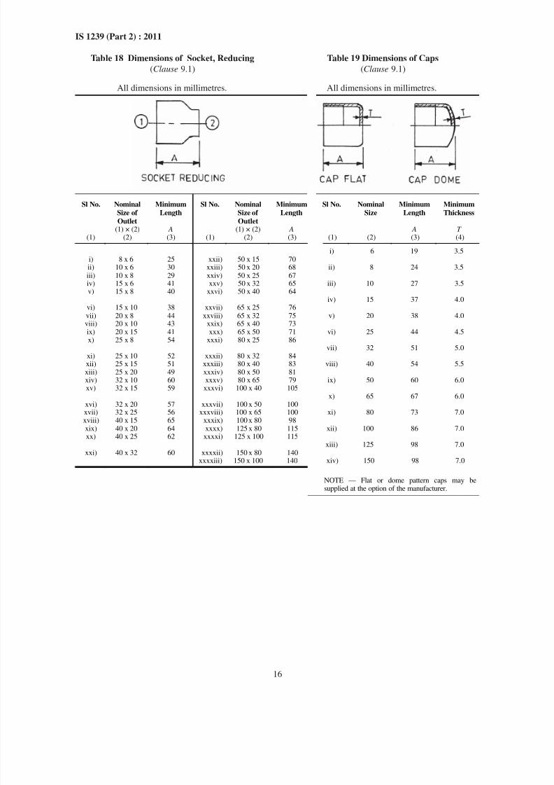
Table 18 Dimensions of Socket, Reducing Table 19 Dimensions of Caps
(Clause 9.1) (Clause 9.1)
All dimensions in millimetres. All dimensions in millimetres.
Sl No. Nominal
Size of
Outlet
Minimum
Length
Sl No. Nominal
Size of
Outlet
Minimum
Length
Sl No. Nominal
Size
Minimum
Length
Minimum
Thickness
(1) × (2) A (1) × (2) A A T(1) (2) (3) (1) (2) (3) (1) (2) (3) (4)
i) 6 19 3.5i) 8 x 6 25 xxii) 50 x 15 70ii) 10 x 6 30 xxiii) 50 x 20 68
iii) 10 x 8 29 xxiv) 50 x 25 67
ii) 8 24 3.5
iv) 15 x 6 41 xxv) 50 x 32 65v) 15 x 8 40 xxvi) 50 x 40 64
iii) 10 27 3.5
vi) 15 x 10 38 xxvii) 65 x 25 76iv) 15 37 4.0
vii) 20 x 8 44 xxviii) 65 x 32 75viii) 20 x 10 43 xxix) 65 x 40 73
v) 20 38 4.0
ix) 20 x 15 41 xxx) 65 x 50 71x) 25 x 8 54 xxxi) 80 x 25 86
vi) 25 44 4.5
xi) 25 x 10 52 xxxii) 80 x 32 84vii) 32 51 5.0
xii) 25 x 15 51 xxxiii) 80 x 40 83xiii) 25 x 20 49 xxxiv) 80 x 50 81
viii) 40 54 5.5
xiv) 32 x 10 60 xxxv) 80 x 65 79xv) 32 x 15 59 xxxvi) 100 x 40 105
ix) 50 60 6.0
xvi) 32 x 20 57 xxxvii) 100 x 50 100x) 65 67 6.0
xvii) 32 x 25 56 xxxviii) 100 x 65 100xviii) 40 x 15 65 xxxix) 100 x 80 98
xi) 80 73 7.0
xix) 40 x 20 64 xxxx) 125 x 80 115xx) 40 x 25 62 xxxxi) 125 x 100 115
xii) 100 86 7.0
xxi) 40 x 32 60 xxxxii) 150 x 80 140xiii) 125 98 7.0
xxxxiii) 150 x 100 140 xiv) 150 98 7.0
NOTE — Flat or dome pattern caps may besupplied at the option of the manufacturer.
8/12/2019 Is 1239 Book
http://slidepdf.com/reader/full/is-1239-book 23/34
8/12/2019 Is 1239 Book
http://slidepdf.com/reader/full/is-1239-book 24/34
18
IS 1239 (Part 2) : 2011
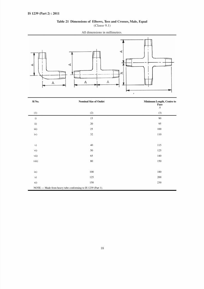
Table 21 Dimensions of Elbows, Tees and Crosses, Male, Equal
(Clause 9.1)
All dimensions in millimetres.
Sl No. Nominal Size of Outlet Minimum Length, Centre toFace A
(1) (2) (3)
i) 15 90
ii) 20 95
iii) 25 100
iv) 32 110
v) 40 115
vi) 50 125
vii) 65 140
viii) 80 150
ix) 100 180
x) 125 200
xi) 150 230
NOTE — Made from heavy tube conforming to IS 1239 (Part 1).
8/12/2019 Is 1239 Book
http://slidepdf.com/reader/full/is-1239-book 25/34
19
IS 1239 (Part 2) : 2011
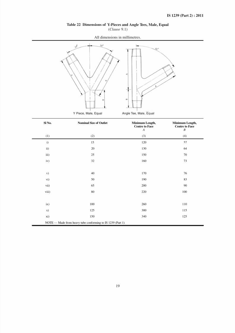
Table 22 Dimensions of Y-Pieces and Angle Tees, Male, Equal
(Clause 9.1)
All dimensions in millimetres.
Y Piece, Male, Equal Angle Tee, Male, Equal
Sl No. Nominal Size of Outlet Minimum Length,Centre to Face
A
Minimum Length,Centre to Face
B
(1) (2) (3) (4)
i) 15 120 57
ii) 20 130 64
iii) 25 150 70
iv) 32 160 73
v) 40 170 76
vi) 50 190 83
vii) 65 200 90
viii) 80 220 100
ix) 100 260 110
x) 125 300 115
xi) 150 340 125
NOTE — Made from heavy tube conforming to IS 1239 (Part 1).
8/12/2019 Is 1239 Book
http://slidepdf.com/reader/full/is-1239-book 26/34
20
IS 1239 (Part 2) : 2011
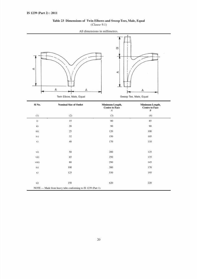
Table 23 Dimensions of Twin Elbows and Sweep Tees, Male, Equal
(Clause 9.1)
All dimensions in millimetres.
Twin Elbow, Male, Equal Sweep Tee, Male, Equal
Sl No. Nominal Size of Outlet Minimum Length,Centre to Face
A
Minimum Length,Centre to Face
B
(1) (2) (3) (4)
i) 15 80 85
ii) 20 90 90
iii) 25 120 100
iv) 32 150 105
v) 40 170 110
vi) 50 200 125
vii) 65 250 135
viii) 80 290 145
ix) 100 380 170
x) 125 530 195
xi) 150 620 220
NOTE — Made from heavy tube conforming to IS 1239 (Part 1).
8/12/2019 Is 1239 Book
http://slidepdf.com/reader/full/is-1239-book 27/34
21
IS 1239 (Part 2) : 2011
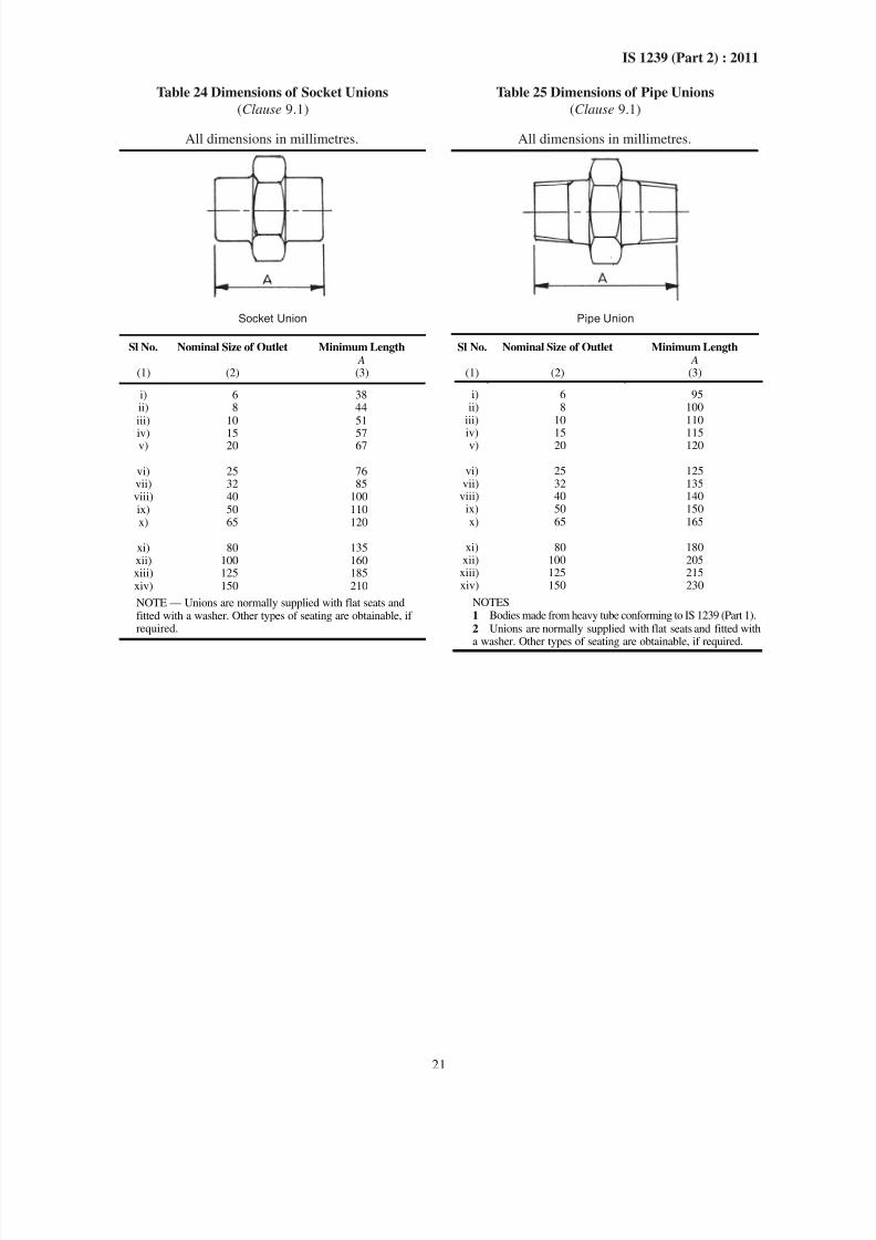
Table 24 Dimensions of Socket Unions
(Clause 9.1)
All dimensions in millimetres.
Socket Union
Sl No. Nominal Size of Outlet Minimum Length A
(1) (2) (3)
i) 6 38ii) 8 44iii) 10 51
iv) 15 57v) 20 67
vi) 25 76vii) 32 85viii) 40 100ix) 50 110x) 65 120
xi) 80 135xii) 100 160xiii) 125 185xiv) 150 210
NOTE — Unions are normally supplied with flat seats andfitted with a washer. Other types of seating are obtainable, ifrequired.
Table 25 Dimensions of Pipe Unions
(Clause 9.1)
All dimensions in millimetres.
Pipe Union
Sl No. Nominal Size of Outlet Minimum Length A
(1) (2) (3)
i) 6 95ii) 8 100
iii) 10 110
iv) 15 115v) 20 120
vi) 25 125vii) 32 135
viii) 40 140ix) 50 150x) 65 165
xi) 80 180xii) 100 205
xiii) 125 215xiv) 150 230
NOTES1 Bodies made from heavy tube conforming to IS 1239 (Part 1).
2 Unions are normally supplied with flat seats and fitted with a washer. Other types of seating are obtainable, if required.
8/12/2019 Is 1239 Book
http://slidepdf.com/reader/full/is-1239-book 28/34
22
IS 1239 (Part 2) : 2011
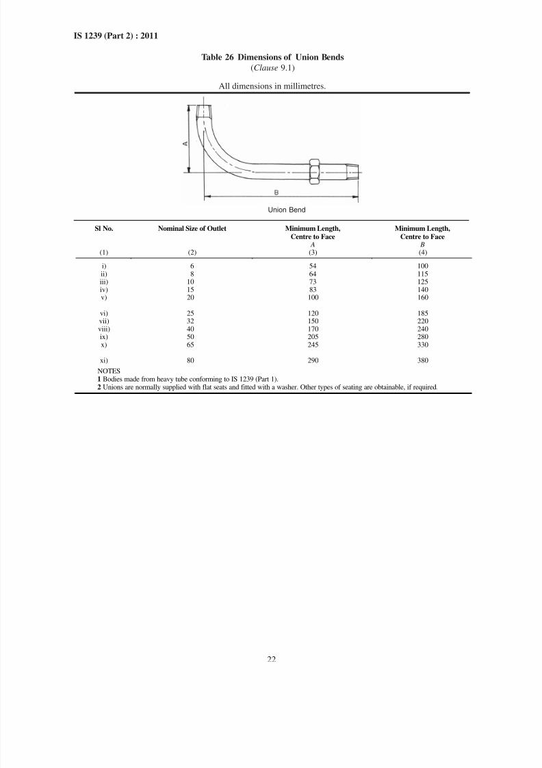
Table 26 Dimensions of Union Bends
(Clause 9.1)
All dimensions in millimetres.
Union Bend
Sl No. Nominal Size of Outlet Minimum Length,
Centre to Face A
Minimum Length,
Centre to Face B
(1) (2) (3) (4)
i) 6 54 100ii) 8 64 115iii) 10 73 125iv) 15 83 140v) 20 100 160
vi) 25 120 185vii) 32 150 220viii) 40 170 240ix) 50 205 280x) 65 245 330
xi) 80 290 380
NOTES1 Bodies made from heavy tube conforming to IS 1239 (Part 1).2 Unions are normally supplied with flat seats and fitted with a washer. Other types of seating are obtainable, if required.
8/12/2019 Is 1239 Book
http://slidepdf.com/reader/full/is-1239-book 29/34
23
IS 1239 (Part 2) : 2011
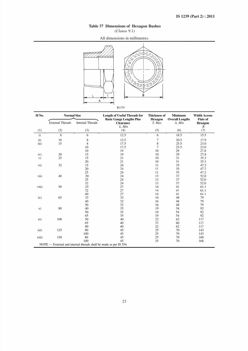
Table 27 Dimensions of Hexagon Bushes
(Clause 9.1)
All dimensions in millimetres.
Normal SizeSl No.
External Threads Internal Threads
Length of Useful Threads for
Basic Gauge Lengths Plus
Clearance L, Min
Thickness of
Hexagon
T, Max
Minimum
Overall Lengths
A, Min
Width Across
Flats of
Hexagon B
(1) (2) (3) (4) (5) (6) (7)
i) 8 6 12.5 6 18.5 15.5
ii) 10 8 12.5 7 20.5 17.9iii) 15 8 17.5 8 25.5 23.0
10 17.5 7 25.5 23.010 19 10 29 27.8
iv) 20 15 19 10 29 27.8v) 25 15 21 10 31 35.3
20 21 10 31 35.3vi) 32 15 24 11 35 47.2
20 24 11 35 47.225 24 11 35 47.2
vii) 40 20 24 13 37 52.025 24 13 37 52.0
32 24 13 37 52.0viii) 50 25 27 14 41 61.132 27 14 41 61.140 27 14 41 61.1
ix) 65 32 32 16 48 7940 32 16 48 7950 32 16 48 79
x) 80 40 35 19 54 9250 35 19 54 9265 35 19 54 92
xi) 100 50 40 22 62 11765 40 22 60 11780 40 22 62 117
xii) 125 80 45 25 70 143100 45 25 70 143
xiii) 150 80 45 25 70 168100 45 25 70 168
NOTE — External and internal threads shall be made as per IS 554.
8/12/2019 Is 1239 Book
http://slidepdf.com/reader/full/is-1239-book 30/34
24
IS 1239 (Part 2) : 2011
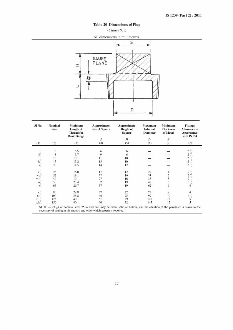
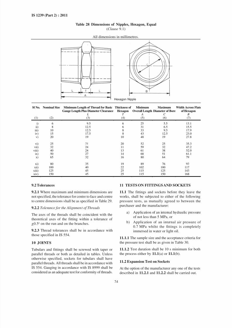
Table 28 Dimensions of Nipples, Hexagon, Equal
(Clause 9.1)
All dimensions in millimetres.
Sl No. Nominal Size Minimum Length of Thread for Basic
Gauge Length Plus Diameter Clearance
Thickness of
Hexagon
Minimum
Overall Length
Maximum
Diameter of Bore
Width Across Flats
of Hexagon
L T A C B(1) (2) (3) (4) (5) (6) (7)
i) 6 9.5 6 25 5.5 13.1ii) 8 12.5 6 31 6.5 15.5
iii) 10 12.5 8 33 9.5 17.9iv) 15 17.5 8 43 12.5 23.0v) 20 19 10 48 19 27.8
vi) 25 21 20 52 25 35.3vii) 32 24 11 59 32 47.2
viii) 40 24 13 61 38 52.0ix) 50 27 14 68 51 61.1x) 65 32 16 80 64 79
xi) 80 35 19 89 76 92xii) 100 40 22 102 100 117
xiii) 125 45 25 115 125 143xiv) 150 45 25 115 150 168
9.2 Tolerances
9.2.1 Where maximum and minimum dimensions are
not specified, the tolerance for centre to face and centre
to centre dimensions shall be as specified in Table 29.
9.2.2 Tolerance for the Alignment of Threads
The axes of the threads shall be coincident with the
theoretical axes of the fitting within a tolerance of
+0.5o on the run and on the branches.
9.2.3 Thread tolerances shall be in accordance withthose specified in IS 554.
10 JOINTS
Tubulars and fittings shall be screwed with taper or
parallel threads or both as detailed in tables. Unless
otherwise specified, sockets for tubulars shall have
parallel threads. All threads shall be in accordance with
IS 554. Gauging in accordance with IS 8999 shall be
considered as an adequate test for conformity of threads.
11 TESTS ON FITTINGS AND SOCKETS
11.1 The fittings and sockets before they leave the
works, shall be subjected to either of the following
pressure tests, as mutually agreed to between the
purchaser and the manufacturer:
a) Application of an internal hydraulic pressure
of not less than 5 MPa, or
b) Application of an internal air pressure of
0.7 MPa whilst the fittings is completely
immersed in water or light oil.
11.1.1 The sample size and the acceptance criteria for
the pressure test shall be as given in Table 30.
11.1.2 Test duration shall be 10 s minimum for both
the process either by 11.1(a) or 11.1(b).
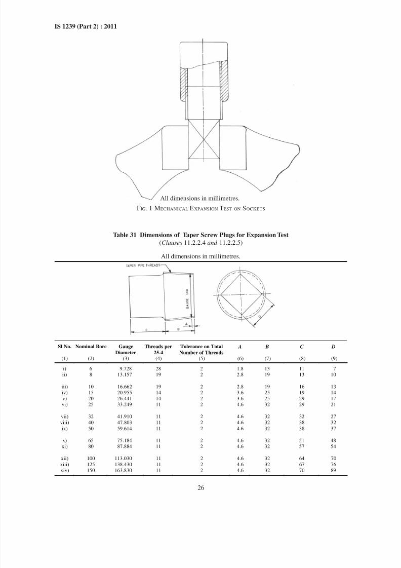
11.2 Expansion Test on Sockets
At the option of the manufacturer any one of the tests
described in 11.2.1 and 11.2.2 shall be carried out.
Hexagon Nipple
8/12/2019 Is 1239 Book
http://slidepdf.com/reader/full/is-1239-book 31/34
8/12/2019 Is 1239 Book
http://slidepdf.com/reader/full/is-1239-book 32/34
26
IS 1239 (Part 2) : 2011
FIG. 1 MECHANICAL EXPANSION TEST ON SOCKETS
Table 31 Dimensions of Taper Screw Plugs for Expansion Test
(Clauses 11.2.2.4 and 11.2.2.5)
All dimensions in millimetres.
Sl No. Nominal Bore Gauge
Diameter
Threads per
25.4
Tolerance on Total
Number of Threads
A B C D
(1) (2) (3) (4) (5) (6) (7) (8) (9)
i) 6 9.728 28 2 1.8 13 11 7
ii) 8 13.157 19 2 2.8 19 13 10
iii) 10 16.662 19 2 2.8 19 16 13
iv) 15 20.955 14 2 3.6 25 19 14
v) 20 26.441 14 2 3.6 25 29 17vi) 25 33.249 11 2 4.6 32 29 21
vii) 32 41.910 11 2 4.6 32 32 27
viii) 40 47.803 11 2 4.6 32 38 32
ix) 50 59.614 11 2 4.6 32 38 37
x) 65 75.184 11 2 4.6 32 51 48
xi) 80 87.884 11 2 4.6 32 57 54
xii) 100 113.030 11 2 4.6 32 64 70
xiii) 125 138.430 11 2 4.6 32 67 76
xiv) 150 163.830 11 2 4.6 32 70 89
All dimensions in millimetres.
8/12/2019 Is 1239 Book
http://slidepdf.com/reader/full/is-1239-book 33/34
27
IS 1239 (Part 2) : 2011
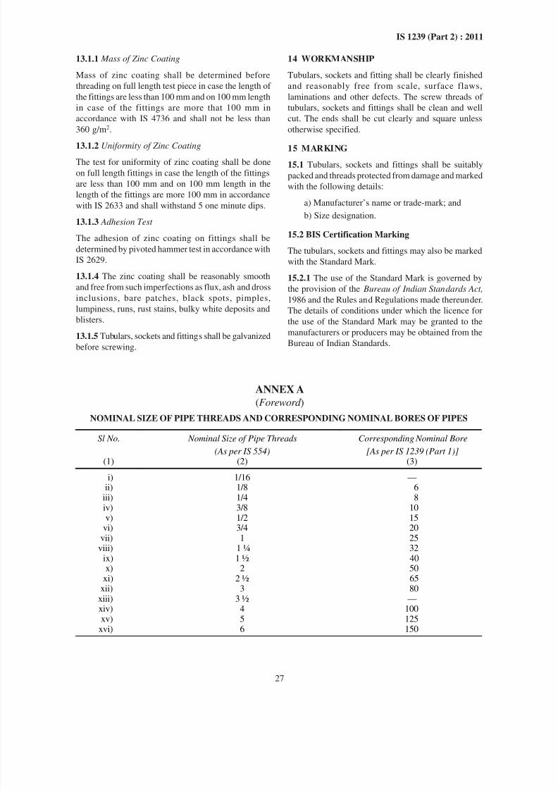
13.1.1 Mass of Zinc Coating
Mass of zinc coating shall be determined before
threading on full length test piece in case the length of
the fittings are less than 100 mm and on 100 mm length
in case of the fittings are more that 100 mm in
accordance with IS 4736 and shall not be less than
360 g/m2.
13.1.2 Uniformity of Zinc Coating
The test for uniformity of zinc coating shall be done
on full length fittings in case the length of the fittings
are less than 100 mm and on 100 mm length in the
length of the fittings are more 100 mm in accordance
with IS 2633 and shall withstand 5 one minute dips.
13.1.3 Adhesion Test
The adhesion of zinc coating on fittings shall be
determined by pivoted hammer test in accordance with
IS 2629.
13.1.4 The zinc coating shall be reasonably smoothand free from such imperfections as flux, ash and dross
inclusions, bare patches, black spots, pimples,
lumpiness, runs, rust stains, bulky white deposits and
blisters.
13.1.5 Tubulars, sockets and fittings shall be galvanized
before screwing.
14 WORKMANSHIP
Tubulars, sockets and fitting shall be clearly finished
and reasonably free from scale, surface flaws,
laminations and other defects. The screw threads of
tubulars, sockets and fittings shall be clean and well
cut. The ends shall be cut clearly and square unless
otherwise specified.
15 MARKING
15.1 Tubulars, sockets and fittings shall be suitably
packed and threads protected from damage and marked
with the following details:
a) Manufacturer’s name or trade-mark; and
b) Size designation.
15.2 BIS Certification Marking
The tubulars, sockets and fittings may also be marked
with the Standard Mark.
15.2.1 The use of the Standard Mark is governed bythe provision of the Bureau of Indian Standards Act,
1986 and the Rules and Regulations made thereunder.
The details of conditions under which the licence for
the use of the Standard Mark may be granted to the
manufacturers or producers may be obtained from the
Bureau of Indian Standards.
ANNEX A
(Foreword )
NOMINAL SIZE OF PIPE THREADS AND CORRESPONDING NOMINAL BORES OF PIPES
Sl No. Nominal Size of Pipe Threads
(As per IS 554)
Corresponding Nominal Bore
[As per IS 1239 (Part 1)](1) (2) (3)
i) 1/16 —ii) 1/8 6
iii) 1/4 8iv) 3/8 10v) 1/2 15
vi) 3/4 20vii) 1 25
viii) 1 ¼ 32ix) 1 ½
40
x) 2 50xi) 2 ½
65
xii) 3 80xiii) 3 ½ —xiv) 4 100xv) 5 125
xvi) 6 150
8/12/2019 Is 1239 Book
http://slidepdf.com/reader/full/is-1239-book 34/34
Bureau of Indian Standards
BIS is a statutory institution established under the Bureau of Indian Standards Act , 1986 to promote
harmonious development of the activities of standardization, marking and quality certification of goods
and attending to connected matters in the country.
Copyright
BIS has the copyright of all its publications. No part of these publications may be reproduced in any form
without the prior permission in writing of BIS. This does not preclude the free use, in the course of
implementing the standard, of necessary details, such as symbols and sizes, type or grade designations.
Enquiries relating to copyright be addressed to the Director (Publications), BIS.
Review of Indian Standards
Amendments are issued to standards as the need arises on the basis of comments. Standards are also reviewed
periodically; a standard along with amendments is reaffirmed when such review indicates that no changes are
needed; if the review indicates that changes are needed, it is taken up for revision. Users of Indian Standards
should ascertain that they are in possession of the latest amendments or edition by referring to the latest issue of
‘BIS Catalogue’ and ‘Standards : Monthly Additions’.
This Indian Standard has been developed from Doc No.: MTD 19 (4999).
Amendments Issued Since Publication
Amend No. Date of Issue Text Affected
BUREAU OF INDIAN STANDARDS
Headquarters:
Manak Bhavan, 9 Bahadur Shah Zafar Marg, New Delhi 110 002
Telephones : 2323 0131, 2323 3375, 2323 9402 Website: www.bis.org.in
Regional Offices: Telephones
Central : Manak Bhavan, 9 Bahadur Shah Zafar Marg 2323 7617
NEW DELHI 110002 2323 3841
Eastern : 1/14 C.I.T. Scheme VII M, V. I. P. Road, Kankurgachi 2337 8499, 2337 8561
KOLKATA 700054 2337 8626, 2337 9120
Northern : SCO 335-336, Sector 34-A, CHANDIGARH 160022 60 384360 9285
Southern : C.I.T. Campus, IV Cross Road, CHENNAI 600113 2254 1216, 2254 1442
2254 2519, 2254 2315
Western : Manakalaya, E9 MIDC, Marol, Andheri (East) 2832 9295, 2832 7858
MUMBAI 400093 2832 7891, 2832 7892
Branches: AHMEDABAD. BANGALORE. BHOPAL. BHUBANESHWAR. COIMBATORE. DEHRADUN.
FARIDABAD GHAZIABAD GUWAHATI HYDERABAD JAIPUR KANPUR LUCKNOW