Embed Size (px)
Citation preview

Disclosure to Promote the Right To Information
Whereas the Parliament of India has set out to provide a practical regime of right to information for citizens to secure access to information under the control of public authorities, in order to promote transparency and accountability in the working of every public authority, and whereas the attached publication of the Bureau of Indian Standards is of particular interest to the public, particularly disadvantaged communities and those engaged in the pursuit of education and knowledge, the attached public safety standard is made available to promote the timely dissemination of this information in an accurate manner to the public.
इंटरनेट मानक
“!ान $ एक न' भारत का +नम-ण”Satyanarayan Gangaram Pitroda
“Invent a New India Using Knowledge”
“प0रा1 को छोड न' 5 तरफ”Jawaharlal Nehru
“Step Out From the Old to the New”
“जान1 का अ+धकार, जी1 का अ+धकार”Mazdoor Kisan Shakti Sangathan
“The Right to Information, The Right to Live”
“!ान एक ऐसा खजाना > जो कभी च0राया नहB जा सकता है”Bhartṛhari—Nītiśatakam
“Knowledge is such a treasure which cannot be stolen”
“Invent a New India Using Knowledge”
है”ह”ह
IS 12431 (1988): Helical-scan video tape cassette systemusing 12.65 mm magnetic tape on type VHS [LITD 7: Audio,Video and Multimedia Systems and Equipment]


UDC 621’397’454 ‘ . ’ .‘- . IS : 12431 - 1988
Indian Standard
HELICAL-SCAN VIDEO TAPE CASSETTE SYSTEM USING 12s65 mm ( 0’5 in ) MAGNETIC
TAPE ON TYPE VHS
SECTION ONE - GENERAL.
1. scope
1.1 This standard is applicable to magnetic video recording using 12.65 mm ( 0.5 in ) tapt cassettes on two-hand helical-scan video cassette recorders and defines the basic VHS forma, video cassette system of 50 Hz-625 lines.
1.2 This standard defines the electrical and mechanical characteristics of equipment which wil provide for the interchangeability of recorded cassettes. The requirements given relate to 625 lint 50 field systems.
2. Environment
2.1 Tests and measurements made on the system to check the requirements of this standard shall be carried out under the following conditions:
Temperature 25 f 1°C
Relative humidity 50 f 2
Barometric pressure 86 kPa to 106 kPa
SECTION
3. Mechanical Parameters
8 TWO - VIDEO TAPE CASSETTE
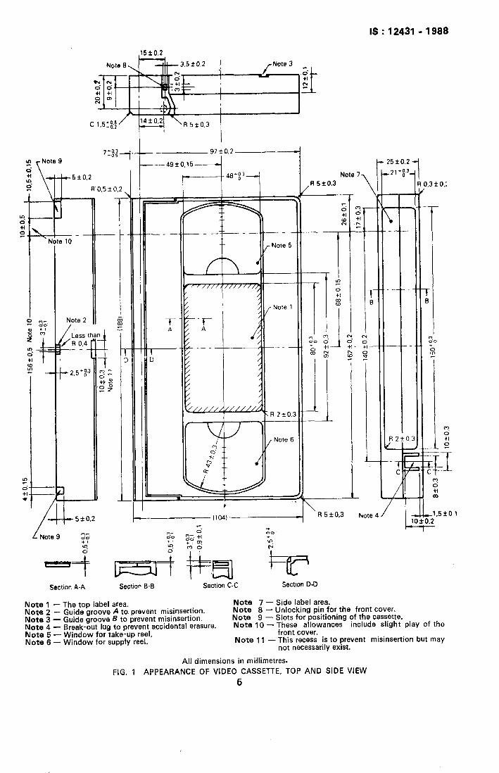
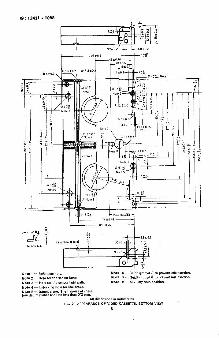
3.1 Cassette Dimensions - The dimensions of the cassette shall be in accordance with Fig. 1 to 4 ( P 5-8 ).
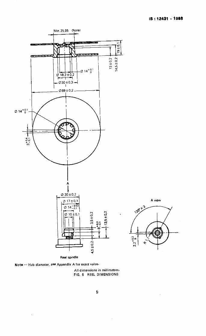
3.2 Reel Dimensions - The dimensions of reel shall be in accordance with Fig. 5 (‘P 9 ) .
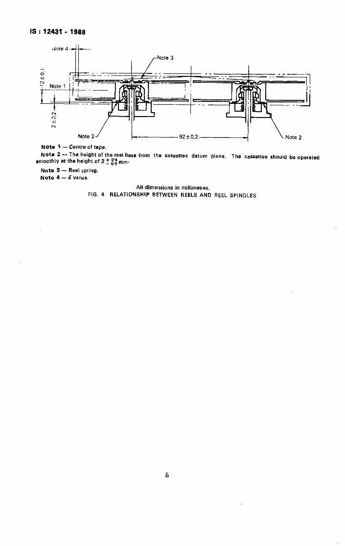
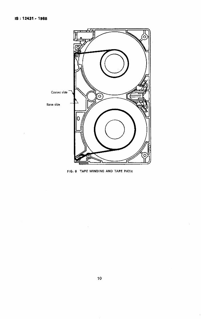
3.3 Tape Widening and Tape Width - The tape winding and the tape path shall be in’accordance with Fig. 6 ( P 10 ). The E value of the tape pack shall be greater than I.5 mm. [ See Note 4 to ?g.4(P8)forEvalue.].
8.4 Unlocking of Front Cover - The unlocking of the front cover shall be accomplished when a ‘orce no greater than 0.15 N is applied to the cover unlocking pin, as shown in Note 8 to :ig. 1 ( P 5 ).
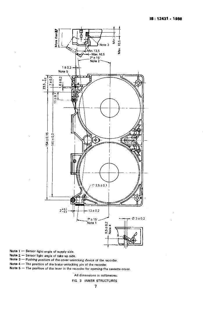
L5 Opening of Front Cover - The force necessary to open the fro&cover as shown in Note 3 tc zig. 3 ( P 7 ) shall be less than 1 N.
L8 Releasing of Reel Brake’- The reel brake shall be released by the reel brake unlocking pin IS shown in Note 4 to Fig. 3,&with a force less than O-7 N.
1.7 Reel Spring - The reels in the cassette shall be pushed down by the reel spring with a force rf 1.6’;:; N, with the reels in the position indicated in Fig. 4 ( P 8 ).
Adopted 22 February 1988 @ March 1989, BIS I Gr 7
BUREAU OF INDIAN STANDARDS ~ANAK 6tibwm. 9 BAHADUR SHAH zAFAR rwwci
NEW DELHI 110002
i :
, i I . . I
‘..,. , .
IS : 12431 - 1988
SECTION THREE - VIDEO CASSETTE RECORDERS
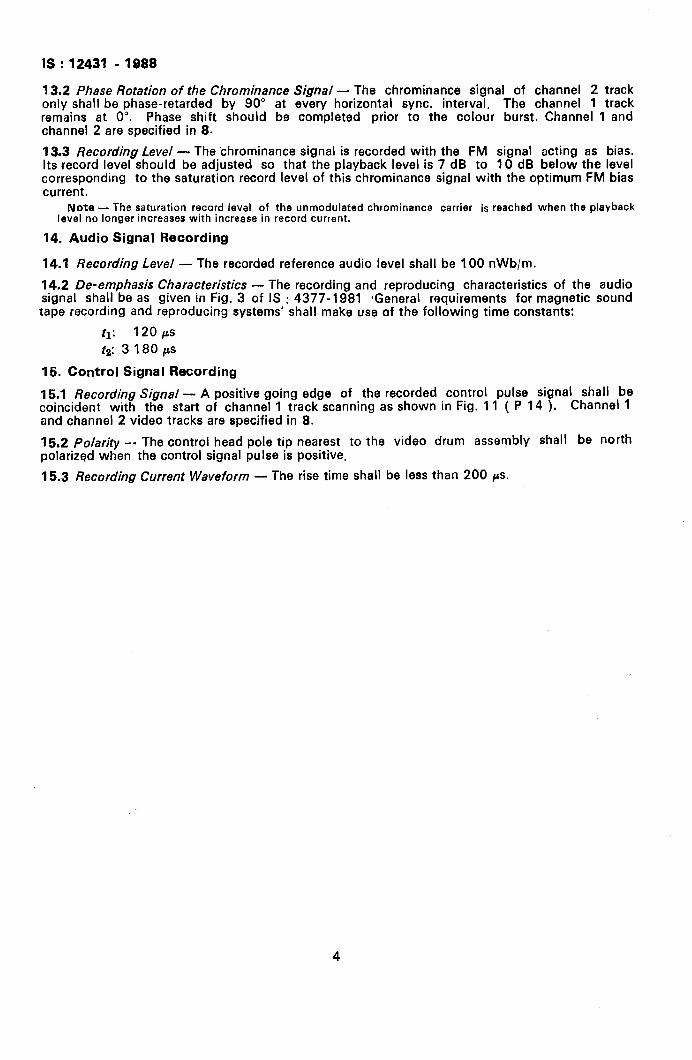
4. Tape Speed
I Standard Speed Tolerance
23.39 mm/s
5. Drum Diameter - The drum diameter shall be 62 f O-01 mm. J
6. Tape Tension - The tape tension during recording and reproducing shall be between 0.30 N and 0.45 N, measured at the entrance of the drum.
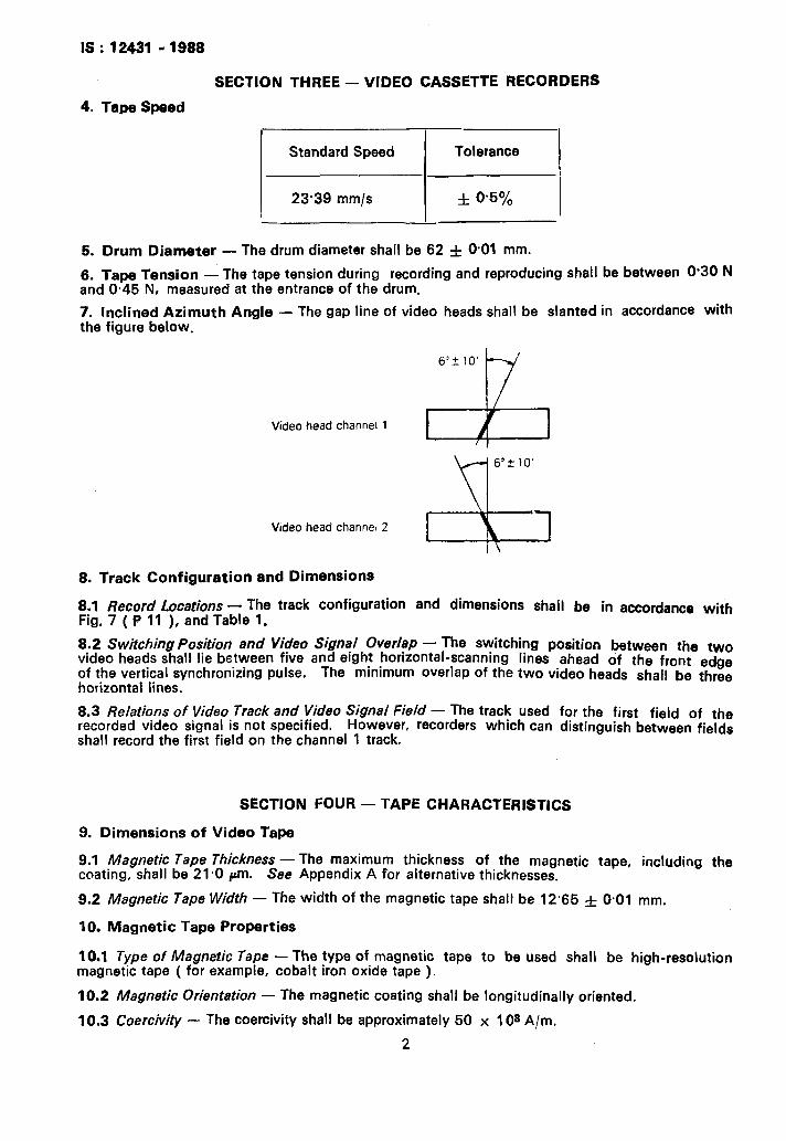
7. Inclined Azimuth Angle - The gap line of video heads shall be slanted in accordance with the figure below.
Videohead channel1 I 1 I ,
Video head channel2
8. Track Configuration and Dimensions
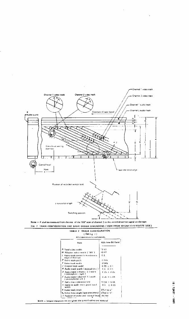
8.1 Record Locations - The track configuration and dimensions shall be in accordance with Fig. 7 ( P 11 ), and Table 1.
8.2 Switching Position and Video Signal overlap - The switching position between the two Video heads shall lie between five and eight horizontal-scanning lines ahead of the front edge of the vertical synchronizing pulse. horizontal lines.
The minimum Overlap Of the two video heads shall be three
6.3 Relations of Video Track and Video Signal Field - The track used for the first field of the recorded video signal is not specified. However, recorders which can distinguish between fields shall record the first field on the channel 1 track.
SECTION FOUR - TAPE CHARACTERISTICS
9. Dimensions of Video Tape
9.1 Magnetic Tape Thickness - coating, shall be 21-O pm.
The maximum thickness of the magnetic tape, including the See Appendix A for alternative thicknesses.
9.2 Magnetic Tape Width - The width of the magnetic tape shall be 12.66 & 0.01 mm.
10. Magnetic Tape Properties
10.1 Type of Magnetic Tape - The type of magnetic tape to be used shall be high-resolution magnetic tape ( for example, cobalt iron oxide tape )_
10.2 Magnetic Orientation - The magnetic coating shall be longitudinally oriented.
10.3 Coercivity - The coercivity shall be approximately 50 x 10s A/m.
2
IS : 12431 -1988
11. Leader Tape and Trailer Tape
11 .l Automatic Stop - The transmittance of the leader and the trailer tape shall be at least 50% to ensure that the automatic stopping device of the machine functions properly at both ends of the magnetic tape.
11.2 Dimensions of Leader and Trailer Tape - Leader and trailer tape length shall be between 130 mm and 190 mm. As for exact length, which is dependent on hub size used, see Appendix A.
Leader and trailer tape thickness shall be 40+_i5 CL m and the width shall be 12.65 f 0.03 mm.
11.3 Splicing - The splice and the attachment of the leader and trailer tape to the hub shall be capable of resisting a force of 30 N. The splicing gap shall be less than 0.07 mm.
SECTION FIVE - RECORDING CHARACTERISTICS
12. FM Recording of Luminance Component
12.1 Low-Pass Filter - The luminance component of the composite video signal shall be separated by a low-pass filter, the attenuation of which is greater than 40 df3 at the chrominance sub-carrier frequency.
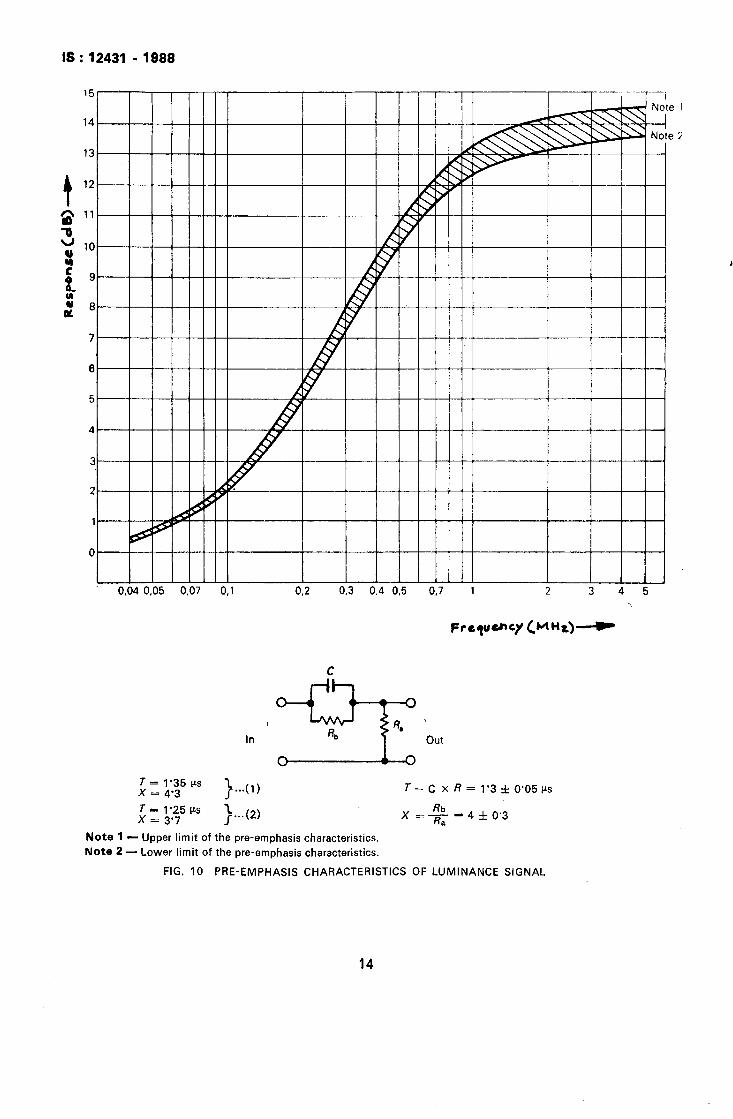
12.2 Pre-Emphasis and Clipping - The luminance signal shall be pre-emphasized and clipped prior to frequency modulation. The characteristics of the pre-emphasis network measured without the low-pass filter are shown in Fig. 10 ( P 13 ), and clipping levels are as follows:
White clipping level: 160t\O% measured from sync. tip.
Dark clipping level: - 40 f 10% measured from sync. tip.
The level from sync. tip to peak white is 100%.
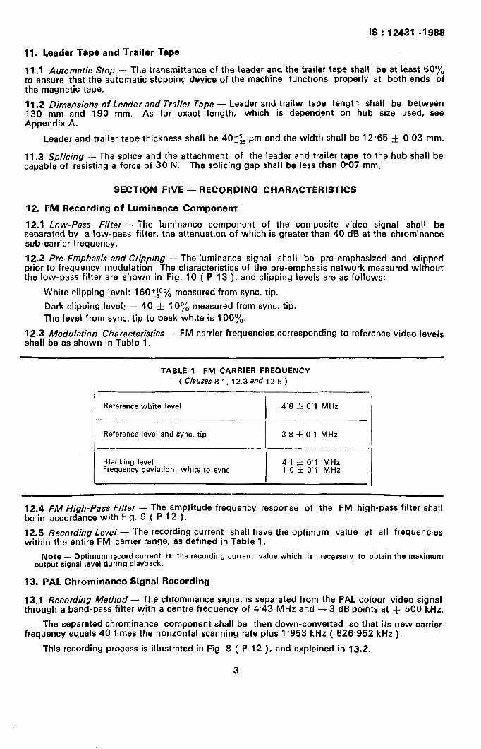
12.3 Modulation Characteristics - FM carrier frequencies corresponding to reference video levels shall be as shown in Table 1.
TABLE 1 FM CARRIER FREQUENCY
( Clauses 8.1, 12.3 and 12.5 ) -.
Reference white level
I 4’8 f 0’1 MHz
Reference level and sync. tip 3’8 f 0’1 MHz
Blanking level
I
4’1 f 0’1 MHz Frequency deviation, white to sync. 1’0 f 0’1 MHz
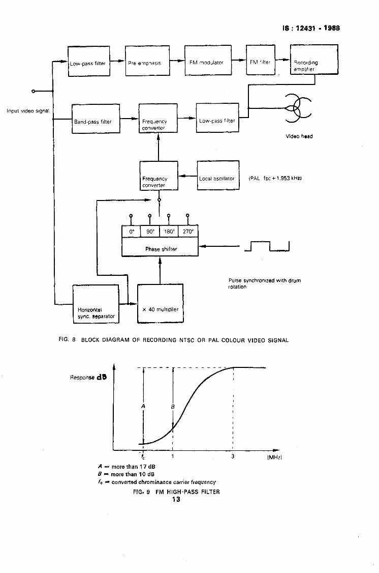
12.4 FM High-Pass Filter - The amplitude frequency response of the FM high-pass filter shall be in accordance with Fig. 9 ( P 12 ).
12.5 Recording Level - The recording current shall have the optimum value at all frequencies within the entire FM carrier range, as defined in Table 1.
Note - Optimum record current is the recording current value which is necessary to obtain the maximum output signal level during playback.
13. PAL Chrominance Signal Recording
13.1 Recording Method - The chrominance signal is separated from the PAL colour video signal through a band-pass filter with a centre frequency of 4.43 MHz and - 3 dB points at f 600 kHz.
The separated chrominance component shall be then down-converted so that its new carrier frequency equals 40 times the horizontal scanning rate plus 1’953 kHz ( 626.952 kHz ),
This recording process is illustrated in Fig. 8 ( P 12 ), and explained in 13.2.
3
IS : 12431 - 1988
13.2 Phase Rotation of the Chrominance Signal - The chrominance signal of channel 2 track only shall be phase-retarded by 90” at every horizontal sync, interval. The channel 1 track remains at 0’. Phase shift should be completed prior to the colour burst. Channel 1 and channel 2 are specified in 8.
13.3 Recording Level - The chrominance signal is recorded with the FM signal acting as bias. Its record level should be adjusted so that the playback level is 7 dB to 10 dB below the level corresponding to the saturation record level of this chrominance signal with the optimum FM bias current.
Note - The saturation record leval of the unmodulated chrominance carrier is reached when the playback level no longer increases with increase in record current.
14. Audio Signal Recording
14.1 Recording Level - The recorded reference audio level shall be 100 nWb/m.
14.2 De-emphasis Characteristics - The recording and reproducing characteristics of the audio signal shall be as given in Fig. 3 of IS : 4377-1981 #General requirements for magnetic sound tape recording and reproducing systems’ shall make use of the following time constants:
t1: 120 /Ls
t2: 3 180 /JS
15. Control Signal Recording
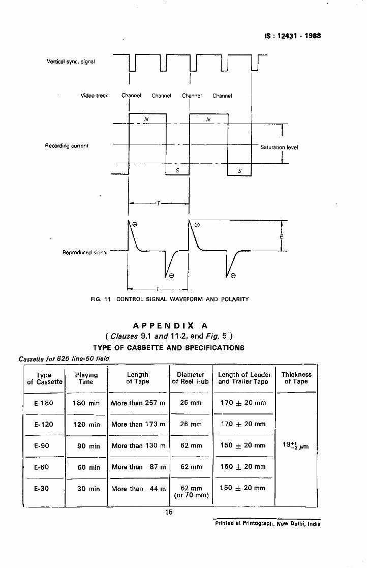
15.1 Recording Signal - A positive going edge of the recorded control pulse signal shall be coincident with the start of channel 1 track scanning as shown in Fig. 11 ( P 14 1. Channel 1 and channel 2 video tracks are specified in 8.
15.2 Polarity -- The control head pole tip nearest to the video drum assembly shall be north polarized when the control signal pulse is positive.
15.3 Recording Current Waveform - The rise time shall be less than 200 P.S.
IS : 12431 - 1988
-49to 15
,~146+~.‘--_I
I ” I 1 Note 7, 1 ,R 5f0.3 D.3 f0.:
Note 4 i
rc
Y-- Note 6
,? _.
,1,5fO 1 1.2 -
-9 Section A-A Section B-B Section C-C Sectlon D-D
Note 1 - The top label area. Note 7 - Side label area. Note 2 - Guide groove A to prevent misinserfion. Note 8 - Unlocking pin for the front cover. Note 3 - Guide groove B to prevent misinsertion. Note 9 - Slots for positioning of the cassette. Note 4 - Break-out lug to prevent accidental erasure. Note 10 - These allowances include slight play of the
z:: : - Window for take-up reel. front cover. - Window for supply reel. Note 11 - This recess is to prevent misinsertion but may
not necessarily exist.
All dimensions in millimetres.
FIG. 1 APPEARANCE OF VIDEO CASSETTE, TOP AND SIDE VIEW
5
IS:12431 -1888
0 9’“o:i: Note -5 -
/ a Not
c 1.5f0.2
Less than N O;! f i-l- 6.9 f 0.2
Note 1 - Reference hole. Note 6 -- Guide groove A to prevent misinsertion.
Note 2 - Hole for the sensor lamp. Note 7 - Guide groove 6 to prevent misinsertion.
Note 3 - Hole for the sensor light path. Note 8- Auxiliary hole position.
Note 4 - Unlocking hole for reel brake.
Note 5 -- Datum plane. The flatness of these four datum planes shall be less than 0’2 mm.
All dimensions in millimetres.
FIG. 2 APPEARANCE OF VIDEO CASSETTE, BOTTOM VIEW
6
IS:l2431-1999
I I
‘4-Y F&15’ Note 1
Note 1 - Sensor light angle of supply side.
Note 2 - Sensor light angle of take-up side. Note 3 - Pushing position of the cover-unlocking device of the recorder.
Note 4 - The position of the brake-unlocking pin of the recorder.
Note 5 - The position of the lever in the recorder for opening the cassette cover.
All dimensions in millimetres.
FIG. 3 INNER STRUCTURES
7
IS:1243161988
Note 1 - Centre of tape.
Note 2 - The height of the reel base from the cassettee datum plane. smoothly at the height of 2 + t:t mm*
The cassettee should be operated
Note 3 - Reel spring.
Note 4 - E value.
All dimensions in millimetres.
FIG. 4 RELATIONSHIP BETWEEN REELS AND REEL SPINDLES
,
8
IS: 12431 - 1988
Mln 25,S5 (Note) I I I
I-- t 030,+0,3-I
I
A
I 0 30f0.2
0 17fO.l
0 141;:y3
0 10fO.l ,’ Tl
” d 0
4-I 4-l
In e pj 22 2
A&
+ml
Reel spindle
Note - Hub diameter, see Appendix A for exact value.
A view
.
All dimensions in millimetres.
FIG. 5 REEL DIMENSIONS
9
IS : 12431 - 1988
Coated side 1
Base side -
FIG. 6 TAPE WINDING AND TAPE PATH
10
/- Channel 1 wdeo track
Note - X shall be measured from the end of the 180’ scan of channel 2 to the recorded control signal on the We.
FIG 7 TRACK CONFIGURATION AND BASK DESIGN DIMENSIONS (VIEW FROM MAGNETO-SENSITIVE SIDE)
TABLE 2 TRACK CONFIGURATION
C Comrol rrack wtdlh R Audio track wdrh ( monoDhonic )

As in the Original Standard, this Page is Intentionally Left Blank
Input video stgnal
I - Low-pass filter
IS : 12431 - 1999
- Pre-emphasis --)- FM modulator - FM filter
,
Band-pass filter - Frequency converter L
4
- Low-pass filter
Video head
(PAL. fsc + 1,953 kHzJ
Horizontal sync. separator
x 40 multiplier
Pulse synchrontzed with drum rotation
FIG. 8 BLOCK DIAGRAM OF RECORDING NTSC OR PAL COLOUR VIDEO SIGNAL
Response dB
_ -___
i
I I t I c
-t 1 3 (MHz)
A = more than 17 dl3
B = more than 10 dB
fc - converted chrominance carrier frequency
FIG. 9 FM HIGH-PASS FILTER
13
IS : 12431 - 1999
‘;’ lo- a I I I IIIII
5 I I I IIIII
k I I IIIIII
el
e2
6
1
In out
T= 1’35 PS x = 4’3 )
. ..(I )
T= 1’25~ i x = 3’7 J...(2)
Note 1 - Upper limit of the pre-emphasis characteristics.
Note 2 - Lower limit of the pre-emphasis characteristics.
FIG. 10 PRE-EMPHASIS CHARACTERISTICS OF LUMINANCE SIGNAL
14
IS : 12431 - 1988
Verticdl sync. signal
Video track
Recording current
I I Channel Channel Channel Channel
I I
N N
_
-_
s S
I Saturation level
1
l-4 T
Reproduced signal
L-------l FIG. 11 CONTROL SIGNAL WAVEFORM AND POLARITY
APPENDIX A
( Clauses 9.1 and 11.2, and fig. 5 )
TYPE OF CASSETTE AND SPECIFICATIONS
Cassette for 625 line-50 field
I Type
of Cassette b
- _
E-l 80
E-120
P-
E-90
E-60
- _
E-30
180 min More than 257 m
120 min More than 173 m
90 min
60 min
30 min
Length of Tape
More than 130 m
More than 87 m
More than 44 m
Diameter )f Reel Hub
26 mm
26 mm
62 mm
62 mm
62 mm (or 70 mm)
Length of Leader and Trailer Tape
170 f 20 mm
-
170 f 20 mm
150 f 20 mm
150 f 20 mm
150 f 20 mm
Thickness of Tape
19+: pm
Printed at Printograph, New Delhi, India