Embed Size (px)
Citation preview
Disclosure to Promote the Right To Information
Whereas the Parliament of India has set out to provide a practical regime of right to information for citizens to secure access to information under the control of public authorities, in order to promote transparency and accountability in the working of every public authority, and whereas the attached publication of the Bureau of Indian Standards is of particular interest to the public, particularly disadvantaged communities and those engaged in the pursuit of education and knowledge, the attached public safety standard is made available to promote the timely dissemination of this information in an accurate manner to the public.
इंटरनेट मानक
“!ान $ एक न' भारत का +नम-ण”Satyanarayan Gangaram Pitroda
“Invent a New India Using Knowledge”
“प0रा1 को छोड न' 5 तरफ”Jawaharlal Nehru
“Step Out From the Old to the New”
“जान1 का अ+धकार, जी1 का अ+धकार”Mazdoor Kisan Shakti Sangathan
“The Right to Information, The Right to Live”
“!ान एक ऐसा खजाना > जो कभी च0राया नहB जा सकता है”Bhartṛhari—Nītiśatakam
“Knowledge is such a treasure which cannot be stolen”
“Invent a New India Using Knowledge”
है”ह”ह
IS 12579 (1988): Base-metal mineral insulated thermocouplecables and thermocouples [ETD 18: Industrial ProcessMeasurement and Control]


,-. t : \_/
IS : 12579 - 1888
Indian Standard
SPECIFICATION FOR BASE METAL MINERAL INSULATED THERMOCOUPLE CABLES AND
THERMOCOUPLES
UDC 621’315’211 [ 621’315’613’9] : 621’362’1
*-\ I . I ,
-v’ @I Co&+.& 1989
BUREAU OF INDIAN STANDARDS MANAK BHAVAN, 9 BAHADUR SHAH ZAFAR MARG
NEW DELHI 110002
Gr 3 August 1989
IS : 12579 - 1988
Indian Standard
SPECIFICATION FOR BASE METAL MINERAL INSULATED THERMOCOUPLE CABLES AND
THERMO-COUPLES
0. FOR
0.1 This Indian Standard was adopted by the Bureau of Indian Standards on 27 October 1988, after the draft finalized by the Industrial Process Measurement and Control Sectional Committee had been approved by the Electro- technical Division Council.
0.2 Mineral insulated thermocouple cables are bendable metal sheathed cables with compacted metal oxide insulation and one or more than one pair of conductors. Mineral insulated thermocouples are made from these type of cables. Although, IS : 7358-1984* specifies the requirements for thermocouples and IS : 2053- 1974? that of the thermocouples pyrometers, it is felt that a separate standard is needed to specify the dimensional details and specific test require-
*Specification for thermocouples (jirst rrvision ).
tSpecification for thermocouples pyrometers (./?rsf revision ) .
EWORD
ments for these special type of thermocouples and thermocouple cables.
0.3 In the preparation of this standard, assis- tance has been derived from IEC 65B ( Secre- tariat ) 98 ‘Base metal mineral insulated thermo- couple cables and thermocouples’, issued by the International Electrotechnical Commission ( IEC) in 1985.
0.4 For the purpose of deciding whether a particular requirement of this standard is complied with, the final value, observed or calculated, expressing the result of a test or analysis, shall be rounded off in accordance with IS : 2-1960*. The number of significant places retained in the rounded off value should be the same as that of the specified value in this standard.
*Rules for rounding off numcricul virlucs (r.&ssd).
1. SCOPE
1.1 This standard specifies the requirements for mineral insulated thermocouple cables and for mineral insulated thermocouples having one pair of base-metal conductors for general industrial applications.
NOTE-Mineral insulatrd cables and thermocouples are also available with more than one pair of conductors.
1.2 This standard does not cover the require- ments for nuclear primary loop applications for which there are special recluirements.
2. TERMINOLOGY
2.0 For the purpose of this standard, the follow- ing definitions, in addition to those given in IS : 1885 (Part 49)-1978* and IS : 7358-1984~ shall apply.
2.1 Mineral Insulated Thermocouple Cables - Bendable metal sheathed cables with
l EIcctrotechnical vocabulary: Part 49 Industrial pro- cess measurement and control.
tSpscilication fur thermocoupler (,firsl rsvision ).
compacted metal oxide insulation and one pair of conductors.
2.2 Mineral Insulated Thermocouples - Thermocouples made from mineral insulated thermocouple cables in accordance with scope of this standard.
2.3 Earthed Junction - A measuring junction electrically connected to the metal sheath.
2.4 Unearthed (Insulated) Junction - A measuring junction electrically insulated from ~lrc metal sheath.
2.5 Cold-End -- Tl~c end of the thermocouple remote from the measuring junction.
3. REFERENCE TABLES
3.1 I:ollowing Indian Standards shall be appli- cable for reference tables:
IS : 2053-1974 Thermocouple pyrometers (first revision )
1
IS t 12579 - 1988
IS : 2054-1962 Reference tables for nickel/ chromium-nickel/aluminium thermo- couples
IS : 2056-1962 Reference tables for copper constantan thermocouples
IS : 2057-1962 Reference tables for iron constantan thermocouples
IS : 7988-1976 Reference tables for chromel- kopal thermocouples
IS : 10625-1983 Reference tables for nickel/ chromium-copper/nickel ( chromel-cons- tantan ) thermocouples
IS : 12051-1987 Reference tables for nickel- chromium-silicon/nickel-silicon ( Nicrosil/ Nisi1 ) Type N
4. DIMENSIONS
4.1 Thermocouple Cables
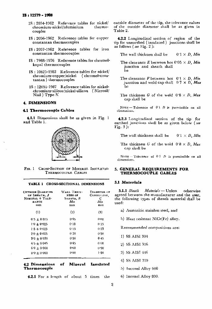
4.1.1 Dimensions shall be as given in Fig. 1 and Table 1.
FIG. 1 CROSS-SECTION OF MINERAL INSULATED THERMOCOUPLE CABLES
5. GENERAL REQUIREMENTS FOR THERMOCOUPLE CABLES
TABLE 1 CROSS-SECTIONAL DIMENSIONS
OUTBIDEDIAM~TER WALL TEICK- DIAMBTER OR or SEEATH, A NE88 OF CONDUCTOR,
NOMINAL + TOLE- SHEATH,E RANCE Min lk&
mm mm mm
(1) (2) (3)
0’5 f 0’025
1’0 f 0’025
1’5 f 0.025
2’0 f 0,025
3’0 f 0’030
4’5 f 0’045
6’0 f 0’060
8’0 f O’OUO
0’05 o.oI.3
0’10 0‘15
0‘15 0’23
0’20 0‘30
0.30 0.45
0’45 0’(;8
U-60 U’9U
O’UO 1’20
4.2 Dimensions of Mineral Insulated Thermocouple
4.2.1 For a length of about 5 times the
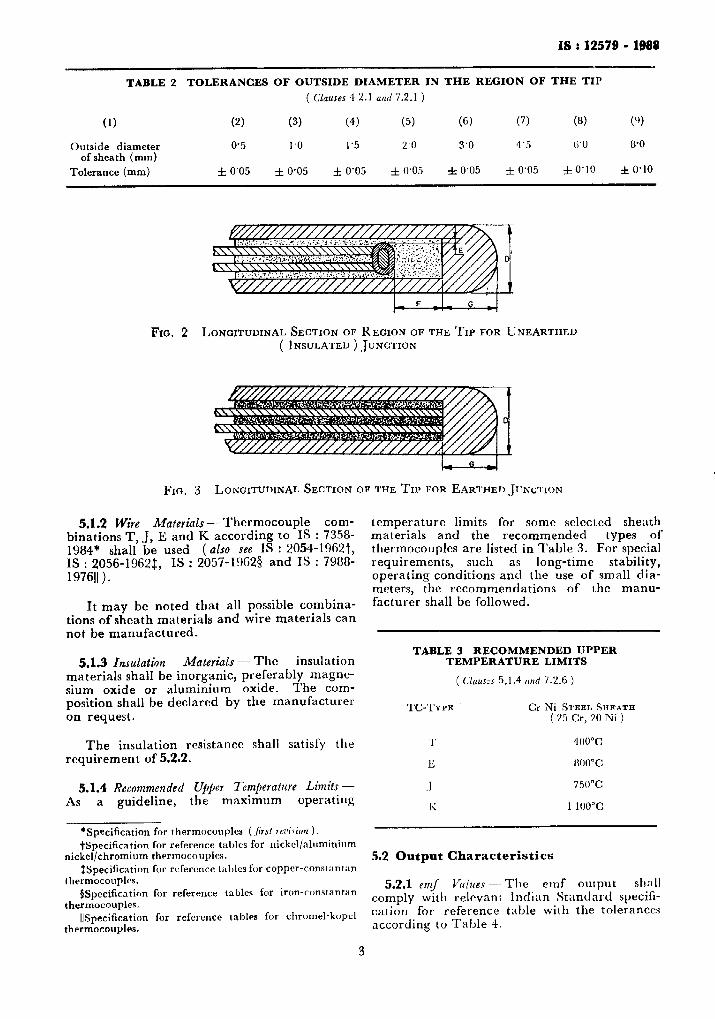
outside diameter of the tip, the tolerance values of the outside diameter shall be as given in Table 2.
4.2.2 Longitudinal section of region of the tip for unearthed (insulated ) junctions shall be as follows (see Fig. 2 ):
The wall thickness shall be 0’1 x D, Mitt
The clearance E between hot 0’05 X D, Min junction and sheath shall be
The clearance F between hot 0’1 x D, Min junction and weld cap shall 0’7 x D, Max be
The thickness G of the weld 0’8 x D, Max cap shall be
3 NOTE-Tolerance ,of 0’1 D is permissible on all
dimensions.
4.2.3 Longitudinal section of the tip for earthed junctions shall be as given below (see Fig. 3):
The wall thickness shall be 0’ 1 x D, Min
The thickness G of the weld 0’8 x D, Max cap shall be
NCJTE ~~ Tolerance of 0.1 D is permissible on all dimensions.
5.1 Materials
5.1.1 Sheath Materials - Unless otherwise agreed between the manufacturer and the user, the following types of sheath material shall be used:
a) Austcnitic stainless steel, and
1,) Heat resistant NiCr(Fe) alloy.
Recommended compositions are:
1) SS AISI 304
2) ss RISI 316
3) SS AIST 446
4) SS AIST 310
5) Inconel Alloy 600
6) lnconel Alloy 800.
2
IS : 12579 - 1999
TABLE 2 TOLERANCES OF OUTSIDE DIAMETER IN THE REGION OF THE TIP
( Clauses 4 2.1 ancl 7.2.1 )
(1) (2) (3) (4) (5) (6) (7) (8) (9)
Outside diameter 0’5 I.0 1’5 20 3’0 4’5 6’0 8’0 of sheath (mm)
Tolerance (mm) f 0’05 f 0’05 f 0’05 f 0’05 + 0’05 f 0’05 f 0’10 f 0’10
Fro. 2 LONGITUDINAL SECTION OF REGION OF THE TIP FOR UNEARTHED ( INSULATED ) .JUNCTION
Jj’~a. 3 LONGITUDINAL SECTION OF THE TIP FOR EARTHED JIJIWIICN
5.1.2 Wire Materials- Thermocouple com- binations T, J, E and K according to IS : 7358-
temperature limits for some selected sheath materials and the recommended types of
1984” shall be used (also see IS : 2054-1962t, thermocouples are listed in Table 3. For special IS : 2056-1962:, IS : 2057-19623 and IS : 7988- requirements, such as long-tlmc stability, 197611). operating conditions and the use of small dia-
meters, the recommendations of the manu- It may be noted that all possible combina- facturer shall be followed.
tions of sheath materials and wire materials can not be manufactured.
TABLE 3 RECOMMENDED UPPER 5.1.3 Insulation Materials - The insulation
materials shall be inorganic, preferably magne- sium oxide or aluminium oxide. The com- position shall be declared by the manufilcturer on request.
The insulation resistance shall satisfy the requirement of 5.2.2.
5.1.4 Recommended Upper Tetnj~erature Limits - As a guideline, the maximum operating
*Specification for I hermocouples ( jirsf rcsi\ion 1.
TEMPERATURE LIMITS
( Cluus~s 5.1.4 crnd 7.2.6 )
‘I‘G’I‘YYE Cr Ni S’I’EEI, SHRATIf ( 25 Cr, 20 Ni )
1 1 400°C
I; fm”c
.J 750°C
I\: 1 lw.YC
tSpecification for reference tables for nickel/nlnminium nickel/chromium thermocouples. 5.2 Output Characteristics
fSpeciIication for rcfercnce tirl,les for copper-constantan thermocouples. 5.2.1 entf Values ~~ The clnf output sh:1ll
$Specification for reference talrlcs for iron-constantan thermocouples. comply with relevant Indian Standard specifi-
IjSpecification for reference tables for chromel-kopcl cation for reference table with the tolerances
thermocouples. according to Table 4.
3
.
IS:12579 - 1988
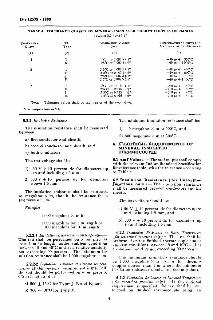
TABLE 1 TOLERANCE CLASSES OF MINERAL INSULATED THERMOCOUPLES OR CABLES
( Clauses 5.2.1 and 6.1 )
TO~RRANCR TC TOLICRANCE VALUEB TEMPERATURE LIMITS FOR CLAMI TYPE (+) VALIDITY or TOLERANCES
(1) (2) (3) (4)
1 : 1°C or 0’007 5 (t). -40 to + 350°C 1’5°C or 0’000 4 (t)* -40 to + I 000”c
2 T 2’5°C or 0’007 5 (t) * -40 to + 400°C
ii
2‘5% cm 0’007 5 (t)* -40 to + 800”c 2’5°C or 0 007 5 (1)’ -40 to + 750°C 2’5°C or 0’007 5 (t)’ -40 to + 1 100DC
3 T 1°C or 0’015 (f)* -200 to f 40°C
I
2’5°C or 0’015 (1). -200 to + 40% 2’5°C or 0’015 (t)* -200 to + 40°C: 2’5°C or 0’015 (1)’ -200 to + 40°C
NoTE-T~I~~xI~~ valuer shall be the greater of the two values.
l t = temperature in “C.
5.2.2 Insulation Resistance
The insulation resistance shall be measured between:
a) first conductor and sheath,
b) second conductor and sheath, and
c) both conductors.
The test voltage shall be:
1) 50 V k 10 percent dc for diameters up to and including 1’5 mm.
2) 500 V f 10 percent dc for diameters above 1’5 mm.
The insulation resistance shall be expressed as megohms x m, that is the resistance for a test piece of 1 m.
Example:
1000 megohms x m is:
I 000 megohms for 1 m length or 100 megohms for 10 m length.
5.2.2.1 Insulation resistance at room temjwature- The test shall be performed on a test piece at least 1 m in length, under ambient conditions between 15 and 40°C and at a relative humidity not exceeding 90 percent. The minimum in- sulation resistance shall be 1 000 megohms x m.
5.2.2.2 Insulation resistance at elevated tempera- tures - If this optional requirement is specified, the test should be performed on a test piece of 0.5 m length and at:
a) 500 f 15% for Types J, E and K; and
b) 300 & 10°C for Type T.
4
The minimum insulation resistance shall be:
1) 5 megohms X m at 5OO”C, and
2) 500 megohms X m at 300°C.
6. ELECTRICAL REQUIREMENTS OF MINERAL INSULATED THERMOCOUPLE
6.1 emf Values - The emfoutput shall comply with the relevant Indian Standard Specification for reference table, with the tolerance according to Table 4.
6.2 Insulation Resistance ( for Unearthed Junctions only ) -The insulation resistance shall be measured between conductors and the sheath.
The test voltage should be:
a) 50 V f 10 percent dc for diameters up to and including 1’5 mm, and
b) 500 V f 10 percent dc for diameters up to and including 1’5 mm.
6.2.1 Insulation Resistance at Room Temperature (for unearthed junctions only ) - The test shall be performed on the finished thermocouple under ambient conditions between 15 and 40°C and at a relative humidity not exceeding 90 percent.
The minimum insulation resistance should be 1 000 megohms x m except for thcrmo- couples shorter than 1 m whet c the minimum insulation resistance should be 1 000 megohms.
6.2.2 Insulation ReJistnrxe at Newted ‘Temperature (fir unearthed junctions only) -~ If this optional requirement is specified, the test shall be per- formed on finished thermocouple using an
IS : 12579 - 1988
insertion length of 300 mm or 50 percent of the 7.2.5 closure Weld Integrity ‘Test - Each thermo- total length of the thermocouple, whichever is couple shall be tested to confirm weld integrity. less, and at 500°C for Types J, E, K and JOO”C This test could be: for -Type T. The minimum insulation resistance shall be 5 megohms for 500 f 15°C and 500 megohms for 350 f 10°C.
7. TESTS
a) Water quench test,
b) Nttrogen pressure test, and
c) Liquid nitrogen immersion test.
7.1 Thermocouple Cables - Unless otherwise stated, the following routine tests shall be per- formed on each coil.
7.1.1 Dimensional Inspection -On one sample of each lot, the outside diameter, wall thickness and the wire diameter shall be measured. Manufacturer’s standard test method may be used.
7.1.2 Insulation Resistance at Room Temperature - The insulation resistance of each coil shall be measured ( see 5.2.2 ).
7.1.3 Verification of the Calibration - Compliance with the specified emf values and tolerances shall be demonstrated by calibration of the sample. The sample shall be fabricated into a thermocouple and calibrated at three or more suitably spaced temperatures covering the temperature range, except that for cryogenic use a single calibration at, for instance, the boiling point of nitrogen ( - 197°C ) is accep- table.
7.1.4 Flewibili~- The cable shall be capable of being bent through a radius of five times its outside diameter.
7.1.5 Electrical Continuiij, - The electrical continuity of each conductor in each length of thermocouple cable shall be verified.
7.2 Mineral Insulated Thermocouple - The following routine tests shall be performed on each thermocouple.
7.2.1 Dimensional Inspection - The tip diameter shall be measured and shall be within the limits of Table 2.
7.2.2 Hoom Temperature Tnsulation Resistance -.- Test conditions and results have to comply with 6.2.1.
7.2.3 Electrical Continuity --~ It shall be ensured that the electrical continuity between both conductors is maintained. No quantitative measurments are required.
7.2.4 Polarity ‘Test - Ed thermocouple having a polarity indication at the termination shall be checked iJy heating or cooling the measuring junction and confirming the specified polarity of electromotive force at the termi- nation.
7.2.5.1 Water quench test - The thermocouple has to be subjected to a minimum temperature of 300°C for a minimum time of 5 min and then immediately plunged into water at room tempe- rature. Then the insulation resistance shall be measured while the thermocouple is immersed. The insulation resistance shall meet the require- ments of 13.2.1.
7.2.5.2 Nitrogen pressure test - The measuring junction end of each probe shall be pressurized for approximately 30 s at a minimum pressure of 2’5 MPa in nitrogen gas, after which the thermocouple tip shall be immediately immersed in water or alcohol. There shall be no bubbling from the closure weld.
7.2.5.3 Liquid nitrogen test - The measuring junction end of each probe shall be immersed in liquid nitrogen until the temperature is stabilized, after which the thermocouple tip shall be immediately immersed in water or alcohol. There shall be no bubbling from the closure weld.
7.2.6 emf Calibraliun - k5:~h thermocouple shall be tested at a temperature not less than 100°C for tolerance classes: 1 and 2 and at a temperature below 100°C for tolerance class 3 to confirm that the calibration meets the tolerance of Table 3.
7.3 Type Tests for Thermocouple
7.3.1 Radiographic Impection - Radiographs of this tip region shall be made in two perpendi- cular planes to confirm that the internal dimen- sions comply with 4.2.2 and 4.2.3.
7.3.2 Eleoated Temperature Insulation Resistance - The test procedure and the requirements shall comply with 6.2.2.
7.3.3 Vkjkation Cal;bta&n - Compliance with the specified ernf values and tolerances shall be verified by the calibration of a sample. The sample shall be calibrated at three or more suitably spaced temperature covering tempc- rature range.
8. SEALING
8.1 The ends of tbc tbcl mocotrples cable shall be sealed prior to sllipping. Seal welding, epoxy or heat-shrink-sleeves may be used.
8.1.1 In case of thermocouple, the cold end shall be sealed prior to testing.
5
IS t 12579 - 1989
9. CLEANING AND PACKAGING
9.1 Thermocouple Cable - Prior to packag- ing, the outer sheaths shall be cleaned free from grease, oil, dirt, scale and other foreign matter.
9.1.1 The cable shall not be coiled to a dia- meter less than 100 times the sheath diameter. The coils shall be bound together to prevent abrasion.
9.2 Material Insulated Thermocouple
9.2.1 Prior to packaging, the sheath shall be cleaned free from grease, oil, dirt, scale and other foreign matter. The thermocouples shall be transported straight or in coils.
9.2.2 When transported straight, they shall be boxed or supported to prevent bending.
9.2.3 When transported coiled, they shall be coiled to a diameter not less than 100 times the sheath diameter. The coils shall be bound together to prevent abrasion.
10. MARKING
l$LIysineral Insulated Thermocouple
10.1.X Each coil shall be marked with at least the following information:
a) Manufacturer’s name,
b) Length of material,
c> Nominal diameter of material,
d) Type of thermocouple,
e) Type of sheath, and
f) Tolerance class.
10.2 The following particulars shall be promi- nently marked ( preferably by way of punching ) on the outer surface of the terminal head:
a) Manufacturer’s name or trade-mark, if any;
b) Type of thermocouple (for example, Cu - con );
c) Nominal length;
d) Working length, if different from nominal length;
e) Continuous maximum temperature range; and
f) Country of manufacture.
10.3 The thermocouple may also be marked with the Standard Mark.
NOFE - The use of the Standard Mark is governed by the provisions of the Bureau of Indian Standards Act 1986 and the Rules and Regulations made there- under. The Standard Mark on products covered by an Indian Standard conveys the assurance that they have been produced to comply with the requirements of that standard under a well defined system of inspection, testing and quality control which is devised and supervised by BIS and operated by the producer. Standand marked products are also continuously checked by BIS for conformity to that standard as a further safeguard. Details of conditions under which a licence for the use of the Standard Mark may be granted to manufacturers or producers may be obtained from the Bureau of Indian Standards.
6
BUREAU OF INDIAN STANDARDS
Haadquartms:
Manak Bhavan, 9 Bahadar Shah Zafar Max-g, NEW DELHI 110002
Telephones: 3 3101 31,3 31 13 75 Telegrams: Manaksanstha
( Common to all Offices)
R8ga!mal O&as: Irleflhonc
Central :
*Eastern :
North 3ru :
Manak Bhavan, 9 Bahadur Shah Zafar Marg, NEW DELHI 110002 t 331 01 31 331 13 75
l/l4 C.I.T. Scheme VII M, V.I.P. Road, Maniktola, CALCUTTA 700054
SC0 445-446, Sector 35-C, CHANDIGARH 160036
Southern : C.I.T. Campus, IV Cross Road, MADRAS 600113
twestern : Manakalaya, E9 MIDC, Marol, Andheri ( East ), BOMBAY 400093
Branch Oj%vs:
‘Pushpak’, Nurmohamed Shaikh Marg, Khanpur, AHMADABAD 380001
#Peenya Industrial Area, 1st Stage, Bangalore-Tumkur Road, BANGALORE 560058
Gangotri Complex, 5th Floor, Bhadbhada Road, T. T. Nagar, BHOPAL 462003
Plot No. 82183, Lewis Road, BHUBANESHWAR 751002
53/5 Ward No. 29, R.G. Barua Road, 5th By-lane, GUWAHATI 781003
5-8-56C, L.N. Gupta Marg ( Nampally Station Road ), HYDERABAD 500001
Rl4 Yudhister Marg, C Scheme, JAIPUR 302005
117/4 18 B Sarvodaya Nagar, KANPUR 208005
Patliputra Industrial Estate, PATNA 800013
T.C. No. 14/1421, Universitv P.O.. Palayam, TRIVANDRUM 695034
{
2 63 48 2 63 49
1
38 49 55 38 49 56
6 67 16
5 36 27
3 31 77
23 10 83
{
6 3471 6 98 32
{
21 68 76 21 82 92
6 23 05
6 21 04 6 21 17
I@sction Ojices ( With Sale Point ):
Pushpanjali, First Floor, 205-A West High Court Road, Shankar Nagar Square, NAGPUR 440010
2 51 71
Institution of Engineers (India) Building, 1332 Shivaji Nagar, PUNE 411005 5 24 35
*Sales Office in Calcutta is at 5 Chowringhee Approach, P.O. Princep Street, Calcutta 700072 27 6u 00
tSales Office in Bombay is at Novelty Chambers, Grant Road, llumbay 400007 8~ 65 2~
#Sales Office in Bangalore is at Unity Building, Narasimharaja Square, Rangalore SWJO2 22 39 71
36 24 99
t
2 1843 3 16 41
41 24 42 41 25 19 41 29 16
6 32 92 95
-~-. _~ _~ _-~-- Printed at Arcee Press, New Delhi, India