Embed Size (px)
Citation preview

Disclosure to Promote the Right To Information
Whereas the Parliament of India has set out to provide a practical regime of right to information for citizens to secure access to information under the control of public authorities, in order to promote transparency and accountability in the working of every public authority, and whereas the attached publication of the Bureau of Indian Standards is of particular interest to the public, particularly disadvantaged communities and those engaged in the pursuit of education and knowledge, the attached public safety standard is made available to promote the timely dissemination of this information in an accurate manner to the public.
इंटरनेट मानक
“!ान $ एक न' भारत का +नम-ण”Satyanarayan Gangaram Pitroda
“Invent a New India Using Knowledge”
“प0रा1 को छोड न' 5 तरफ”Jawaharlal Nehru
“Step Out From the Old to the New”
“जान1 का अ+धकार, जी1 का अ+धकार”Mazdoor Kisan Shakti Sangathan
“The Right to Information, The Right to Live”
“!ान एक ऐसा खजाना > जो कभी च0राया नहB जा सकता है”Bhartṛhari—Nītiśatakam
“Knowledge is such a treasure which cannot be stolen”
“Invent a New India Using Knowledge”
है”ह”ह
IS 1359 (1992): Electroplated coatings of tin [MTD 7: LightMetals and their Alloys]


IS 1359 : 1992 I
Indian Standard
ELECTROPLATEDCOATINGSOFTIN- SPECIFICATION
( Third Revision )
December 1992
U DC 669.687
0 BIS 1992
BUREAU OF INDIAN STANDARDS MANAK BHAVAN, 9 BAHADUR SHAH ZAFAR MARG
NEW DELHI 110002
Price Group 6

Metallic and Non-metallic Finishes Sectional Committee, MTD 20
FOREWORD
This Indian Standard ( Third Revision ) was adopted by the Bureau of Indian Standards, after the draft finalized by the Metallic and Non-metallic Finishes Sectional Committee had been approved by the Metallurgical Engineering Division Council.
This standard was first published in 1959 and subsequently revised in 1966 and 1971.
This standard is based on the practices generally followed in the country in this field. While reviewing the standard, need was felt to revise this standard to align various requirements in line with the International standards. In this revision, the following main modifications have been made:
a) Service grades have been reduced to four, and
b) Corrosion requirements of tin coatings have been incorporated.
In the formulation of this standard, assistance have been derived from IS0 2093 : 1986 ‘Electroplated coatings of tin’, issued by the International Organization for Standardization.
For the purpose of deciding whether a particular requirement of this standard is complied with, the final value, observed or calculated, expressing the result of a test or analysis, shall be rounded off in accordance with IS 2 : 1960 ‘Rules for rounding off numerical values ( revised )‘. The number of significant places retained in the rounded off value should be the same as that of the specified value in this standard.

Is 1359 : 1992
Indian Standard
ELECTROPLATED COATINGS SPECIFICATION
( Third Revision )
OF TIN -
1 SCOPE
1.1 This standard specifies the requirements for electroplated tin coatings of not less than 99.5 percent tin applied to fabricated articles of Iron, Steel, Nickel alloys and Copper and copper alloys containing more than 50 percent of copper. It also covers coatings brightened by fusion in hot oil after electrodeposition, the process being known as flow-brightening or flow melting.
1.2 This standard does not, however, cover coat- ings on:
a) threaded components;
b) tin-coated copper wire;
c) coatings on sheet, strip or wire in unfabri- cated form or on articles made from them;
d) coatings in coil springs;
4
f)
g)
coatings applied by chemical means ( Immersion, autocatalytic or electroless );
electroplating of steels with tensile strength greater than 1 000 Mpa ( or of correspon- ding hardness ); because such steels are subject to hydrogen embrittlement ( see 7.2 ) ; and
aluminium and zinc alloys.
2 REFERENCES
The Indian Standards listed below are necessary adjuncts to this standard:
IS .No.
193 : 1982
265 : 1976
715 f Part 2 ) : 1976
2384 : 1963
Title
Soft solder (fourth revision )
Hydrochloric acid ( secotrd revision )
Coated abrasives: Part 2 Special and mechanized appli- cation ( third revision )
Tin anodes for electroplating
3 TERMINOLOGY
For the purpose of this standard, the following definition shall apply.
3.1 Significant Surface
The surface agreed upon between the purchaser and the elecrroplater, and indicated on the drawing or suitably marked on a sample with
particular reference to the surface not to be plated.
NOTE - Surfaces on which a controlled deposit can- not ordinarily be obtained, such as holes, recesses, bases of angles and similar areas, are normally exempted from the reqmrements for significant surfaces, unless they are specially designated as such.
3.2 Flow-Melting, Fusing, Flow-Brightening, Reflowing
A process by which a coating is melted in order to impact desirable properties such as brightness or improved solderabnity \ see 9.2.1.1 ).
4 INFORMATlON TO BE SUPPLIED BY THE PUHCHA~ER TO THE ELECTROYLATER
4.1 Essential Information
The following information shall be supplied by the purchaser to the electroplater:
a) the number of this standard;
b) the nature of the basis material ( see 5.1 );
c) the service grade number t see 6.1 ) or the classification code of: the coatmg requued ( see 6.2 );
d) the signiticant surface of the article to be electroplated indrcated, for example, by drawmgs or by the provision ot suitably marked samplt s; and
e) the method adhesion testing to be used ( see 9.3 ).
4.2 Additional Information
The followmg additional information may be re- quired and, if so, shall be specified by the purchaser:
a) any heat treatment required ( see 7 );
b) any requirements for porosity testing ( see 9.4.2 ),
c) any requirement for solder-ability testing and the test methods and conditionr to be apphed ( see 9.5 ),
d) any special requirements for undercoats ( see 8 ),
e) a sample showing the required hnish ( see 5.3.1 ),
1
ES 1359 : 1992
f ) any special pretreatment requirement,
g) any specific requirements for the purity of the coating,
h) any special packaging requirements for plated componects, and
j ) any special post-plating treatment.
5 MATERIAL AND WORKMANSHIP
5.1 Basis Material
This standard specifies no requirements for the condition, finish or surface roughness of the basis material prior to electroplating.
5.2 Material
The material shall be such as will produce tin coating conforming to this specification, The anode shall be of pure tin complying with the requirements of IS 2384 : 1963.
5.3 Workmanship
Over the area of the significant surface, the plated article shall be free from visible plating defects, such as blisters, pits or unplated areas, and shall not be stained or discoloured. The plated surface shall be white, of a smooth texture, and be free from nodules. Flow-brightened coat- ings shall be free from de-wetted areas.
5.3.1 The article shall be clean and free from damage. When necessary, a preliminary sample showing the required finish shall be supplied or approved by the purchaser.
6 CLASSIFICATION
6.1 Service Grade Number
The service grade number indicates the severity of the service grade in accordance with the following scale:
4 : Exceptionally Severe - for example service outdoors in severe corrosive conditions or con- tact with food or drink where a complete cover of tin has to be maintained against corrosion and abrasion. 3 : Severe - for example service outdoors in typical temperature conditions. 2 : Moderate - for example service indoors with some condensation.
1 : Mild - for example service indoors in dry atmospheres or applications where soldera- bility is the primary requirement.
NOTE - See 9.1 which gives guidance on the relation between service grade number and minimum thick- ness.
When specifying the service grade number or coating classification code, it should be noted that tin is susceptible to damage in abrasive environ- ments or in those containing certain organic vapours.
6.2 Coating Classification Code
The coating classification code shall consist of four parts, the first two of which shall be separat- ed by an oblique stroke, as follows:
a/b c d
where,
indicates the chemical symbol for the basis metal ( or for the main constituent, if an alloy );
indicates the chemical symbol for the under- coat metal ( or for the main constituent, if an alloy ) followed by a figure for its mini- mum coating thickness, in micrometres, and is omitted if no undercoat is required [ see 4.2 (d) 1;
indicates the chemical symbol for tin, Sn, followed by a figure for its minimum thick- ness, in micrometres;
indicates the surface finish, by the symbol m if the coating is matt, or b if it is bright electroplated or f if it is 8ow-melted.
An example is
Fe/Ni 2.5 Sn 5 f
which represents as iron or steel basis metal, with a 2.5 pm mckel undercoat, tin electroplated to a coating thickness of 5 pm and flow-melted.
7 HEAT TREATMENT
7.1 When required by the purchaser, certain steels should be treated as described in 7.2 to reduce the risk of damage due to hydrogen embrittlement.
7.1.1 Stress Relief Before Plating
Severely cold-worked steels or parts made from steel of tensile strength of 100 MN/ma or greater which have been ground or subjected to severe machining after tempering shall normally be stress-relieved by maintaimng them at 200 & 10°C for not less than one hour or, preferably, for 30 minutes at the highest temperature within the limit imposed by the tempering temperature.
7.1.2 Some steels which have been carburized, flame-hardened or induction-hardened and sub- sequently ground would be impaired by the above treatment, and shall instead be stress-relieved at 140 f 10°C for not less than 5 hours.
7.2 Hydrogen Embrittlement Relief After Electroplating
Because diffusion of hydrogen through tin is very slow, heat treatment for hydrogen embri ttlement relief after electroplating is impractical.
2

8 REQUIREMENTS FOR UNDERCOATS
8.1 Undercoats may be necessary on certain basis materials for any of the following reasons:
a) to prevent diffusion,
b) to retain solderability,
c) to ensure adhesion, and
$) to improve protection against corrosion.
8.2 Care should be taken to select an undercoat or undercoat system that will not confer undesi- rable properties such as embrittlement of the basis material or finished article. For example the use, of highly stressed nickel should be avoided
8.3 If the basis material is a copper alloy con- taining zinc as an alloying constituent, and solderable properties are required, a nickel or copper undercoat of minimum local thickness 2.5 pm is essential in addition to the specified coating thickness of tin such coatings may also be necessary to retain good appearance and adhesion.
8.4 If an undercoat is specified, its nature and minimum local thickness ( see 9.1 ) shall be specified by the purchaser.
The thickness of the undercoat or undercoats shall be meabured by the appropriate method specified in Annex A.
9 PLATING REQUIREMENTS
9.1 Thickness
Tin coatings are classified by thickness and for each service grade ( see 6.1 ), minimum values are specified in Table 1.
9.1.1 The thickness of the coating shall be mea- sured over a reference area by the appropriate method given in Annex A on any part of the significant surface that can be touched with a 20 mm diameter ball In the case of articles having a significant surface area of 100 mm* or
IS 1359 : 1992
greater, the minimum thickness shall be regarded as the minimum value of local thickness. In the case of article having a significant surface area of less than 100 mm*, the minimum thickness shall be regarded as the minimum values of average thickness ( see Annex B ).
9.1.2 In the case of printed circuit boards with electroplated-through holes, the requirements shall apply to the surface within the holes, as well as to the areas that can be touched with a 20 mm diameter ball.
9.1.3 In the case of flow-melted coatings, the thickness requirements apply to the as-electro- plated condition, prior to flow-melting.
9.2 Plating
9.2.1 Application
Tin shall be deposited on the articles after com- pleting operations, such as machining, brassing, welding and forming. Tin shall be deposited directly on the basis metal without preliminary coating of other metals.
9.2.1.1 When tin is plated on the article for soft soldering purposes, it may be How-melted at a temperature between 250% and 26O’C to over- come difficulties in soldering during long periods of storage.
9.3 Adhesion
The coating shall withstand either of the tests given in Annex C. The flaking and blistering of the coating shall be taken as evidence of unsatis- factory adhesion.
9.4 Corrosion/Porosity
[f specifird by the purchaser, coatings having a minimum thickness of 10 microns or greater, shall be subjected to a corrosion test for ferrous basis material and porosity test for non-ferrous basis material.
Table 1 Coating Thicknesses
( Clnuse 9.1 )
Service Grade Copper Basis Materialst) Other Basis Material Number r---_---A_-- -_-_-..7 &_,---_--h--__--_-_~
( Partial ) Minimum ( Partial ) Minimum Class& ation Thickness Classification Thickness
Code Code pm
(1) 12) t”j; (4) (5) 4 Sn 30 30 Sn 30 30 3 Sn 15 15 Sn 20 20 2 Sn 8 10 Sn 12 12 1 Sn 5 5 Sn 5 5
1) Attention is drawn to the essential requirement in 8 for undercoats on copper alloy basis materials that contain zinc as an alloying constituent.
3
1s 1359 : 1982
9.4.1 Corrosion Test
The test shall be conducted as per Annex E. The coated item shall be subjected to a 24 hours salt spray test. After removal from the salt spray ( fog ) cabinet examine the items The appear- ance of more than 6 corroded areas that are visible to the unaided eye per sq cm of surface or any corroded areas larger than 1.6 mm in diameter shall be cause for rejection. For purpose of this requirement, a corroded area is defined as exposure or corrosion of the basis metal.
9.4.2 Porosio Test
The test shall be conducted as per Annex F.
9.5 Solderability
The samples shall be considered solderable if they have a uniform coating, free from dsconti- nuities or breaks visible to unaided eye. When so specified by the purchaser, samples of tin coating on copper and copper alloys shall be subjected to preliminary artificial ageing treatment as given in Annex D.
NOTE - The object of this preliminary treatment is to demonstrate whether articles may be expected to retain thrir solderability during periods of storage. The period of storage at room temperatures whrch produces an effect equivalent to the trst procedure can not be precisely stated but it is probably some years.
10 SAMPLING AND INSPECTION
10.1 Sampling for Production Control
Statistical quality control is recommended for controlling the quality of tin-plated articles. For
this purpose, it is recommended that samples should be taken from a portion where it is likely to give the minimum thickness of plating. The tests specified in 9 shall be conducted on such samples.
10.2 Sampling for Acceptance of a Lot
For the purpose of sampling, a lot shall be divided into sub-lots consisting of 100 articles or part thereof of only such articles as are electroplated at one time in the same bath. Two samples shall be selected from each sub-lot and subjected to the tests specified in 9.
10.2.1 Criteria for Acceptance
If these samples stand the tests, the sub-lot repre- sented by them shall be accepted. If one or both the samples should fail, two further samples shall be selected from the same sub-lot and subjected to the tests. If these samples stand the tests, the sub-lot shall be considered as conforming to the standard.
IO.3 When the consignment is made of small articles plated in a barrel, the number to be tested shall be agreed to between the plater and the purchaser.
11 MARKING
The marking related to the tin coating shall include classification number as specified in this standard and the name or trade-mark of the manufacturer.
ANNEX A
( Clauses 8.4 and 9.1 1 )
METHOD FOR THE DETERMINATION OF LOCAL THICKNESS
A-l OVERCOATING
On ferrous articles electrodeposit 1.3 pm of copper followed by a thickness of not less than 50 pm of nickel. For copper base article electrodeposit a thickness of not less than 50 pm of nickel or copper on that sample.
A.2 MOUNTING AND PREPARATION OF SECTIONS
A-2.1 Section the overcoated sample at one or more positions, Mount the section by moulding in a suitable material SO that the plated surface is perpendicular to the face which is to be prepa- red for examinationn and so that the section is
- r) A deviation of 10 degrees from the perpendicular intro- duces an error of 2 percent in thickness.
4
rigidly held, there being no void between the plated surface and the mounting material.
A-2.1.1 Polish the mounted section, using succes- sively finer abrasives, the last which shall not be coarser than IS grit No. 40 ( 500-micron ) [ see IS 715 ( Part 2 ) : 1976 1. Final polishing may be carried out on a low speed polising wheel using suitable polishing media.
A-2.1.2 It is recommended that the surface should be lightly etched with a suitable reagent in order to improve the contrast between the deposit and the adjacent metal and to remove any soft metal which may have spread over a hard metal.

IS 1359 t 1992
A-3 MEASUREMENT OF THE THICKNESS magnification. OF DEPOSIT A-3.1 Project the image of the section on to the
A-3.1.1 Alternatively, measure the thickness with
screen of a metallographic microscope at a known a metallurgical microscope fitted with a micro-
and properly calibrated magnification. Measure meter eye-piece which has been calibrated against
the thickness of the deposit on the projected an accurately graduated scale.
image accurately with a graduated linear scale A-3.1.2 In either case, the magnifications shah and determine the actual thickness of the deposi- be sufficient to allow the actual thickness of ted metal by dividing this measurement by the deposit to be determined to h1.2 pm.
ANNEX B ( Clause 9.1.1 )
METHOD FOR THE DETERMINATION OF AVERAGE THICKNESS
B-l GENERAL
When small articles are to be tested it is con- venient to perform a single determination of average thickness on a number of samples taken from a batch.
B-2 STRIPPING SOLUTION
Dissolve 20 g of antimony trioxide in 1 000 ml of cold concentrated hydrochloric acid ( d = 1.16 ) ( conforming to IS 265 : 1976 ).
B-3 PROCEDURE
Carefully clean a plated part of known area, free it from grease by means of a suitable solvent treatment, thoroughly dry it and weigh it to an accuracy of one part in 1000. Sufhcient area of sample should be taken to give a weight loss on stripping of at least 0*2 g of tin. Immerse it totally in the stripping solution and turn it over so that the liquid has free access to all surfaces. A fresh
portion of the stripping solution should be used in each test; at least 100 ml of the solution should be used to remove 1 g of tin. Allow the sample to remain in the solution for a period of one minute after gas evolution has ceased. Remove the part, wash it immediately in running water, mop it with a wet soft cloth or cotton wool swab to remove the black powdery deposit of antimony. Dry it and reweigh.
B-4 CALCULATION
Thickness of tin coating in pm = 137 X lo3 (ml -mJ mi crometre s
A
where ml = original mass of the part in g, m2 = final mass of the part in g, and A - area of coating in square millimetres.
NOTE - The above calculation assumes a specific gravity of 7’30 fur tin.
ANNEX C
( Clause 9.3 )
ADHESION TEST
C-l BURNISHING TEST FOR ADHESION edgewise and broadside. Maintain a pressure
C-l.1 Rub an area of not more than 25 mm x sufficient to burnish the film at every stroke, but
25 mm of the plated surface, selected at the not so great as to cut the deposit.
discretion of the inspector, rapidly and firmly for C-2 QUENCHING TEST FOR ADHESION 15 seconds with a smooth metal implement.
C-2.1 Heat the plated articles in an oven to a C-1.1.1 A suitable burnishing implement is a temperature of 185 f 5%. Quench the articles copper disc, for example, a copper coin used in water at room temperature.
5

IS i359’: $992
ANNEX D
( Clause 9.5 )
SOLDERABILITY TEST
,
D-l TEST SAMPLE D-3 ARTIFICIAL AGEING
For small articles of suitable shape and size the whole article should be tested. For larger articles, cut a portion of suitable size of testing. A recommended panel size is 25 mm x 25 mm. For articles not falling into the categories, sampling shall be as agreed to between the plater and the purchaser.
D-2 EQUIPMENT REQUIRED
D-2.1 Solder Pot
D-3.1 Place the sample for test in a suitable vessel above boiling water and leave it there, with the water boiling continuously for 8 hours. Keep the vessel covered and ensure that the sample does not come into contact with the wall of the vessel and that its lower edge is not less than 50 mm or more than 100 mm above the surface of the boiling water. Arrange the cover on the vessel and the steam condensed water over the sample.
Electrically heated and maintained at 250 -& 5 “C.
D-2.2 Solder
D-3.2 Disregard any discolouration of the sample occurring during this ageing treatment. After the 8 hour treatment, remove the sample from the steam and allow it to dry to air.
Complying with Grade Sn 60 of IS 193 : 1982 in sufficient volume to ensure that the temperature remains substantially uniform when introducing the test sample.
D-4 PROCEDURE
D-2.3 Plux
Consisting of a solution containing 25 percent by weight of water white rosin and 75 nercent bv
Coat the sample with flux by immersion. Ensure that the whole surface of the solder bath is clean and bright by skimming it with a steel scraper, and immediately lower the sample into the bath at a speed of approximately 25 mm/s. Leave it immersed for 5 seconds and then withdraw it at the rate of approximately 25 mm/s, holding at stationary just above the solder surface until the coating solidifies.
‘ .- ,
weiiht of isopropyl alcohol ( 99 percent pure ), free from other additives.
ANNEX E ( Clause 9.4.1 )
CORROSION TEST
E-l TEST SOLUTION
The test solution shall be prepared by dissolving sodium chloride in distilled or de-ionized water to produce a concentration of 50 f 5 g/l. The sodium chloride shall be white and shall give a colourless solution in water. It shall be substan- tially free from copper and nickel and shall not contain more than 0.1 % of sodium iodide and not more than 0.4 o/o of total impuritiescalculated for dry salt. If thePH of the solution as prepared is outside the range 6.0 to 7-O the presence of undesirable impurities in the salt or the water or both shall be investigated.
E-l.1 ThepH of the salt solution shall be adjust- ed so that the #H of sprayed solution collected within the test cabinet ( see E-2.4 ) will be between 6.5 and 7.2. Control ofpH shall be based on electrometric measurement at 25°C but a short-range #H paper which can be read in
increments of 0.3 $H unit or less and which has been calibrated against electrometric measure- ments may be used in routine checks. Any necessary correction shall be made by additions of solutions of hydrochloric acid or sodium hydroxide of analytical grade.
Attention is drawn to the possible changes in fiH resulting from loss of carbon dioxide from the solution when it is sprayed. Such changes may be avoided by reducing the carbon dioxide content of the solution by, for example, heating it to a temperature above 35°C before it is placed in the apparatus or by making the solution from freshly boiled water.
E-l.2 The soluticn shall be filtered before it is placed in the reservoir of the apparatus, in order to remove any solid matter which might block the apertures of the spraying device.
6
IS 1359 : 1992
E-2 APPARATUS
The apparatus shall comprise the following com- ponents.
E-2.1 Spray Cabinet made of, or lined with, material resistant to corrosion by the sprayed solution. The cabinet shall have a capacity of not less than 0.2 ms and preferably of not less than 0.4 ms since, with smaller volumes, difficul- ties are experienced in ensuring even distribution of spray. The upper parts shall be so shaped that drops of sprayed solution accumulated on them do not fall on specimens being tested,
The size and shape of the cabinet shall be such that the quantity of solution collected in the cabinet is within the limits stated in E-5.
E-2.2 Means of Supplying and Controlling Heat, adequate to maintain the cabinet and its contents at the specified temperature ( see E-5 ). The tem- perature shall be controlled by a thermostat element placed either within the cabinet at least 100 mm from the walls or in a water jacket on the cabinet. In either case the thermometer, capable of being read from the outside, shall be placed within the cabinet at least 100 mm from the walls.
E-2.3 Means for Spraying the Salt Solution, comprismg a supply of clean air of controlled pressure and humrdity, a reservoir to contain the solution to be sprayed and one or more atomizers made of material resistant to the solution.
The compressed air supply to the atomizers shall be passed through a filter to remove all traces of oil or solid matter and shall be at a pressure of 70 to 170 kPa1). In order to prevent evaporation of water from the sprayed droplets, the air shall be humidified before entering the atomizer by passage through a saturation tower containing water at a temperature several degrees higher than that of the cabinet. The appropriate temperature depends on the pressure used and on the type of atomizer nozzle and shall be adjusted so that the rate of collection of spray in the cabinet and the concentration of the collected spray are kept within the specified limits ( see E-5 ).
The reservoir to contain the solution to be spray- ed shall be a tank made of material resistant to the solution and shall be provided with means of maintaining a constant level of solution in the reservoir.
The atomizers shall be made of inert material, for example glass of plastics material. Baffles may be used to prevent direct impingement of spray on the test specimens and the use of adjustable baffles is helpful in obtaining uniform distribution of spray throughout the cabinet.
r) 1 kPa = 1 kN/ma = PO1 atm.
E-2.4 Suitable Collecting Devices ( at least two ), which shall be funnels of glass or other chemically inert material with the stems inserted into gradu- ated cylinders or other containers. Funnels with a diameter of 100 mm have a collecting area of approximately 80 cm’. The collecting devices shall be placed in the zone of the cabinet where the test specimens are placed, one close to an inlet af spray and one remote from an inlet. They shall be so placed that only spray and not liquid fal1in.g from specimens or from parts of the cabinet 1s collected.
NOTE - If the eauioment has been I’lsed for a saiav , test or for anv &ihe> purpose with solution diffdring from that specified for the test to be carried out, it shall be thoroughly cleaned before use.
E-3 TEST SPECIMENS
The number and type of test specimens, their shape and their dimensions shall be selected according to the specification covering the coating or product being tested. When not so specified, details concerning the specimens shall be mutually agreed between the interested parties.
E-3.1 The specimens shall be thoroughly cleaned before testing. The cleaning method employed shall depend on the nature of the surface and the contaminants, and shall not include the use of any abrasives or solvents which may attack the surface of the specimens.
Care shall be taken that specimens are not recon- taminated after cleaning by excessive or careless handling.
E-3.2 If test specimens are cut from a larger coated article, the cutting shall be carried out in
such a way that the coating is not damaged in the area adjacent to the cut. Unless otherwise speci- fied, the cut edges shall be adequately protected by coating them with a suitable medium, stable under the conditions of the test, such as paint, wax or adhesive tape.
E-4 METHOD OF EXPOSURE OF TEST SPECIMENS
The specimens shall be so placed in the cabinet that they are not in the direct line of travel of spray from the atomizer. Baffles may be used to prevent direct impact of the sprayed solution on the specimens.
The angle at which the sample is exposed in the cabinet is very important The surface shall, in
principle, be flat and placed in the cabinet facing upwards at an angle as close as possible to 20° to the vertical. This angle shall, in all cases, be within the limits 15” to 30”.
In the case of irregular surfaces, for example entire components, these limits shall be adhered to as closely as possible,
7

IS 1359 : 1992
‘The specimens shall be so arranged that they do not come into contact with one another or with the cabinet and that surfaces to be tested are exposed to free circulation of spray. Specimens may be placed at different levels within the cabi- net as long as the solution cannot drip from specimens or their supports at one level onto other specimens placed below.
The support for the specimens shall be made of inert non-metallic material such as glass, plastics or suitably coated wood. If it is necessary to sus- pend test specimens, the material used shall on no account be metallic and shall be synthetic fibre, cotton thread or other inert insulating material.
E-5 OPERATING CONDITIONS
The temperature inside the spray cabinet shall be 35 f 2°C with the minimum possible fluctuation throughout the cabinet during the test.
The solution collected in each of the collecting devices ( see E-2.4 ) shall have a sodium chloride concentration of 50 & 10 g/l and a@H value in the range 6.5 to 7.2 ( see E-l.1 ),
The average rate of collection of solution in each device measured over a minimum period of 24 h shall be 1 to 2 ml/h for a horizontal collecting area of 80 cm*.
Test solution which has been sprayed shall not be reused.
E-6 DURATION OF TESTS
The period of test shall be as designed by the specification covering the coating or product being tested. When not specified, it shall be mutually agreed between the interested parties.
Recommended periods of exposure are 2 h - 6h-24h -448h-96h-240h-480h- 720 1~.
Spraying shall not be interrupted during the prescribed test period. The cabinet shall be opened only for brief visual inspections of the test specimens in position and for replenishing the salt solution in the reservoir if such replenishing cannot be carried out from outside the cabinet.
If the end-point of the test depends on the appea- rance of the first sign of corrosion, the specimens will need to be inspected frequently. For this reason such specimens shall not be tested together with other specimens requiring tests of pre&ter- mined duration.
A periodic vrsual examination of specimens under test for a predetermined period may be made but the surfaces under test shall not be disturbed and the period for which the cabinet is open shall be the minimum necessary to observe and record any visible changes.
E-7 CLEANING OF SPECIMENS AFTER TEST
At the end of the test period, remove the speci- mens from the cabinet. Allow the specimens to- dry for 0.5 to 1 h before rinsing, in order to- reduce the risk of removing corrosion products. Before they are examined, carefully remove resi- dues of the spray solution from their surfaces. A suitable method is to rinse or dip the specimens. gently in clean running water at a temperature not exceeding 40°C and then to dry them imme-- diately in a steam of compressed air at a pressure not exceeding 200 kPa, at a distance to approxit mately 3(JO mm.
E-8 EVALUATION OF RESULTS
Many different criteria for the evaluation of the results of the test may be applied to meet parti- cular requirements for example change in mass alteration revealed by micrographic examination or change in mechanical properties Usually the appropriate criteria will be indicated in the speci- fication for the coating or product tested. For most routine applications of the test, only the following need to be considered:
a) appearance after test;
b) ~PP earance after removing superficial corrosion products;
c) the number and distribution of corrosion defects, that is, pits, cracks, blisters; and
d) the time elapsing before the appearance of the first sign of corrosion.
E-9 TEST REPORT
E-9.1 The test report shall indicate the outcome of the test according to the criteria for evaluation of results prescribed for the test. The result obtained for path specimen tested and, when appropriate, the average result for a group of replicate test specimens shall be reported. The report may, if required, be accompanied by photographic records of the tested specimens.
The report shall contain information about the test procedure. The information may vary accord- ing to the purposes of the test and to the direction prescribed for it but a general list of the details likely to be required is as follows:
a> b)
cl
d)
the description of the coating or product tested;
dimensions and shape of the test specimen and the nature and area of the surfdce tested;
preparation of the test specimen, including any cleaning treatment applied and any protection given to edges or other special areas;
known characteristics of any coating, with. an indication of the surface finish;
8
IS 1359 : 1992
e)
f)
the number of test specimens subjected to the test representing each coating or product; the method used to clean test specimens after the test with, when appropriate, an indication of the loss in mass resulting from the cleaning operation;
8) the angle at which the tested surfaces were
inclined;
h) the test temperature;
j) the duration of test;
k) the properties of any test panels placed in the cabinet expressly to check the corsect- ness of the operating conditions and the results obtained with them.
ANNEX F ( Clause 9.4.2 )
POROSITY TEST
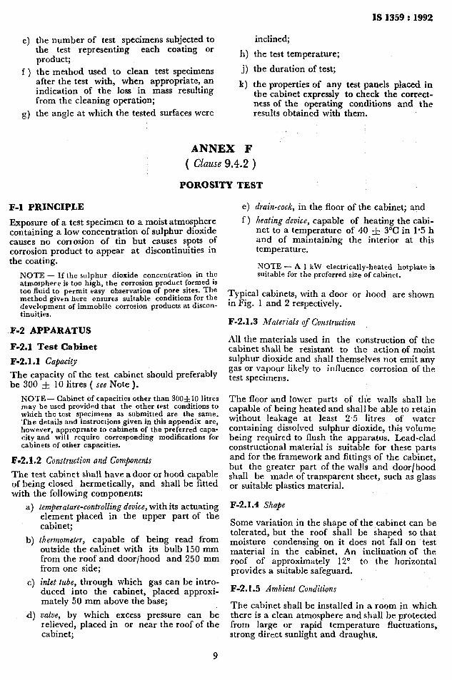
F-l PRINCIPLE
Exposure of a test specimen to a moist atmosphere containing a low concentration of sulphur dioxide causes no corrosion of tin but causes spots of corrosion product to appear at discontinuities in the coating.
NOTE - If the sulphur dioxide concentration in the atmosphere is too high, the corrosion product formed is too fluid to permit easy observation of pore sites. The method given here ensures suitable conditions for the development of immobile corrosion products at discon- tinuitjes.
F-2 APPARATUS
F-2.1 Test Cabinet
F-2.1.1 Cafiacity
The capacity of the test cabinet should preferably be 300 f 10 litres ( see Note ).
NOTE- Cabinet of capacities other than 300flO litres may be used provided that the other test conditions to which the test specimens as submitted are the same. The details and instructions given in this appendix are, however, approprsate to cabinets of the preferred capa- city and will require corresponding modifications for cabinets of other capacities.
F-2.1.2 Construction and Components
The test cabinet shall have a door or hood capable of being closed hermetically, and shall be fitted with the following components:
b)
C>
4
temfierature-controlling device, with its actuating element placed in the upper part of the cabinet;
thermometer, capable of being read from outside the cabinet with its bulb 150 mm from the roof and door/hood and 250 mm from one side;
inlet tube, through which gas can be intro- duced into the cabinet, placed approxi- mately 50 mm above the base;
valve, by which excess pressure can be relieved, placed in or near the roof of the cabinet;
9
e> f 1
drain-cock, in the floor of the cabinet; and
heating device, capable of heating the cabi- net to a temperature of 40 f 3°C in I*5 h and of maintaining the interior at this temperature.
NOTE - A I kW electrically-heated hotplate is suitable for the preferred size of cabinet.
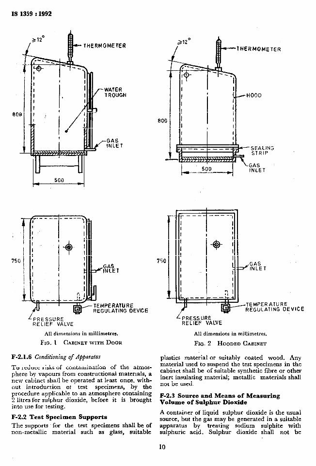
Typical cabinets, with a door or hood are shown in Fig. 1 and 2 respectively.
F-2.1.3 Materials of Construction
All the materials used in the construction of the cabinet shall be resistant to the action of moist sulphur dioxide and shall themselves not emit any gas or vapour likely to influence corrosion of the test specimens.
The floor and lower parts of the walls shall be capable of being heated and shall be able to retain without leakage at least 2.5 litres of water containing dissolved sulphur dioxide, this volume being required to flush the apparatus. Lead-clad constructional material is suitable for these parts and for the framework and fittings of the cabinet, but the greater part of the walls and door/hood shall be made of transparent sheet, such as glass or suitable plastics material.
F-2.1.4 Shape
Some variation in the shape of the cabinet can be tolerated, but the roof shall be shaped so that moisture condensing on it does not fall on test material in the cabinet. An inclination of the roof of approximately 12“ to the horizontal provides a suitable safeguard.
F-2.1.5 Ambient Conditions
The cabinet shall be installed in a room in which there is a clean atmosphere and shall be protected from large or rapid temperature fluctuations, strong direct sunlight and draughts.
THERMOMEtER
REGULATING DEVICE
LPRESSURE RELIEF VALVE
All dimensions in millimetres.
FIQ. 1 CABINET WITH DOOR
F-2.1.6 Conditioning of Apparatus
To reduce risks of contamination of the atmos- phere by vapours from constructional materials, a new cabinet shall be operated at least once, with- out introduction ot test specimens, by the procedure applicable to an atmosphere containing 2 litres for sulphur dioxide, before it is brought into use for testing.
F-2.2 Test Specimen Supports
The supports for the test specimens shall be of non-metallic material such as glass, suitable
HERMOMETER
-SEALING STRIP
GAS INLET
VICE
L PRESSURE RELtEF VALVE
All dimensions in millimetres.
FIG. 2 HOODED CABINET
plastics material or suitably coated wood. Any material used to suspend the test specimens in the cabinet shall be of suitable synthetic fibre or other inert insulating material; metallic materials shall not be used.
F-2.3 Source and Means of Measuring Volume of Sulphur Dioxide
A container of liquid sulphur dioxide is the usual source, but the gas may be generated in a suitable apparatus by treating sodium sulphite with sulphuric acid. Sulphur dioxide shall not be
10

IS 1359 : 1992
generated inside the cabinet. The volume of gas delivered into the chamber may be measured by say suitable method, for example:
a) by means of a gas burette using viscous liquid paraffin as the pressure-controlling fluid; as the volume to be measured is usually about 0.2 htre, measures shall be taken to avoid errors from causes such as air contained in delivery tubes between the burette and the chamber;
b) by means of a gas jar of known volume filled with sulphur dioxide and opened in the chamber;
c) by means of a calibrated flowmeter.
F-3 CONSTRUCTION AND CLEANING OF TEST SPECIMENS
F-3.1 If test specimens are cut from a larger coated article, the cutting shall be carried out in such a way that the coating is not damaged, especially in the area adjacent to the cut. Unless otherwise specified, the cut edges shall be ade- quately protected by coating them with a suitable medium that is stable under the conditions of the test, such as wax or adhesive tape.
F&2 The test specimens shall be thoroughly cleaned before testing. The cleaning method em- ployed shall depend on the nature of the surface and the contaminants, but shall not include the use of any abrasives, solvents or other materials that may attack the surface of test specimens. Care shall be taken that the test specimens are not recontaminated, after cleaning, by excessive or careless handling.
NOTE - The number and type of test specimens and their shaue and dimensions are not saecified. these should be agreed between interested parties ( see also F-4.3 and F-4.4 ) .
F-4 METHOD OF EXPOSURE OF TEST SPECIMENS
F-4.1. When in position in the cabinet, the test specimens shall be located so that no part of any specimen is within 20 mm of another specimen or within 100 mm of the walls or the roof of the cabinet or within 200 mm of the surface of the water in the base of the cabinet.
F-4.2 The test specimens shall be so arranged that any moisture condensing on any of them or on their supports does not fall on other specimens placed at lower levels.
F-4.3 The orientation of the exposed test surface is critical, and in the case of flat surfaces, the angle of inclination to the vertical, unless other- wise specified, shall be 15 f 2”.
F-4.4 The total exposed surface area of the speci- men or specimens tested at any one time shall be substantially the same and, unless otherwise agreed, shall be 0.5 & 0.1 ms for the cabinet of preferred capacity ( see F-2.1.1 ) and proportion- ately changed for different sizes of cabinet.
F-5 PROCEDURE
F-5.1 Introduce 2 f 0.2 litres of distilled water into the base of the cabinet.
NOTE - The quantity of water in the cabinet depends on its size and shape. A proportional change for cabinet of different size is valid only for cabinets of similar shape.
F-5.2 Place the test specimens in position and close the door/hood of the cabinet completely.
F-5.3 Introduce O-2 Iitre of the sulphur dioxide into the chamber.
F-5.4 Switch on the heater and raise the tem- perature inside the cabinet to 40 -& 3°C in approximately I.5 h. Maintain heating, under control, so as to keep the temperature inside the cabinet at 40 f 3°C for 24 h.
F-6 INSPECTION AND CLEANING OF SPECIMENS AFTER TEST
At the end of the 24 h test duration, remove the test specimens from the cabinet and, before they are examined, allow them to hang freely in a normal indoor atmosphere until any liquid corro- sion products have solidified. Examine all the test specimens first with all corrosion products in position. Any cleaning subsequently carried out shall depend on the criteria laid down for evaluation of the result of the test.
11

Standard Mark I The use of the Standard Mark is governed by the provisions of the Bureau of Indian
Standards Act, 1986 and the Rules and Regulations made thereunder. The Standard Mark on products covered by an Indian Standard conveys the assurance that they have been produced to comply with the requirements of that standard under a well defined system of inspection, testing and quality control which is devised and supervised by BIS and operated by the producer. Standard marked products are also continuously checked by BIS for con- formity to that standard as a further safeguard. Details of conditions under which a licence for the use of the Standard Mark may be granted to manufacturers or producers may be obtained from the Bureau of Indian Standards.
Bureau of Indian Standards
BIS is a statutory institution established under the Bureau of Indian Standards Act, 1986 to promote harmonious development of the activities of standardization, marking and quality certification of goods and attending to connected matters in the country.
Copyright
BIS has the copyright of all its publications. No part of these publications may be reproduced in any form without the prior permission in writing of BIS. This does not preclude the free use, in the course of implementing the standard, of necessary details, such as symbols and sizes, type or grade designations. Enquiries relating to copyright be addressed to the Director ( Publications ), BIS.
Review of Indian Standards
Amendments are issued to standards as the need arises on the basis of comments. Standrds are also reviewed periodically; a standard along with amendments is reaffirmed when such review indicates that no changes are needed; if the review indicates that changes are needed, it is taken up for revision. Users of Indian Standards should ascertain that they are in possession of the latest amendments or edition by referring to the latest issue of ‘BIS Handbook’ and ‘Standards Monthly Additions’. Comments on this Indian Standard may be sent to BlS giving the following reference:
Dot : No. MTD 20 ( 3572 )
Amendments Issued Since Publication
Amend No. Date of issue Text Affected
BUREAU OF INDIAN STANDARDS
Headquarterrr
Manak Bhavan, 9 Bahadur Shah Zafar Marg, New Delhi 110002 Telephones t 331 0131,331 13 75
Regional Offices I
Central ! Manak Bhavan, 9 Bahadur Shah 2afa.r Mara NEW DELHI 110002
Eastern ; 1 14 C. I. T. Scheme VII M, V. I. P. Road, Maniktola c! ALCUTTA 700054
Northern ; SC0 445-446, Sector 35-C, CHANDIGARH 160036
Telegrams t Manaksanstha ( Common to all offices )
Telephone
t 331 01 31 331 13 75
t 37 84 99, 37 85 61 37 86 26, 37 86 62
I
53 38 43, 53 16 40 53 23 84
Southern t C. I. T. Campus. IV Cross Road, MADRAS 600113 j 235 02 16, 235 04 42
Western f Manakalaya, E9 MIDC, Marol, Andheri ( East ) BOMBAY 400093
1 235 15 19, 235 23 15
632 92 95, 632 78 58 632 78 91, 632 78 92
Branches : AHMADABAD. BANGALORE. BHOPAL. BHUBANESHWAR. COIMBATORE. FARIDABAD.- GHAZIABAD. GUWAHATI. HYDERABAD. JAIPUR. KANPUR. LUCKNOW. PATNA. T$IIRUVANANTHAPURAM.
anted at New India Rintinl Press. Khuria. lmdla