Embed Size (px)
Citation preview
Disclosure to Promote the Right To Information
Whereas the Parliament of India has set out to provide a practical regime of right to information for citizens to secure access to information under the control of public authorities, in order to promote transparency and accountability in the working of every public authority, and whereas the attached publication of the Bureau of Indian Standards is of particular interest to the public, particularly disadvantaged communities and those engaged in the pursuit of education and knowledge, the attached public safety standard is made available to promote the timely dissemination of this information in an accurate manner to the public.
इंटरनेट मानक
“!ान $ एक न' भारत का +नम-ण”Satyanarayan Gangaram Pitroda
“Invent a New India Using Knowledge”
“प0रा1 को छोड न' 5 तरफ”Jawaharlal Nehru
“Step Out From the Old to the New”
“जान1 का अ+धकार, जी1 का अ+धकार”Mazdoor Kisan Shakti Sangathan
“The Right to Information, The Right to Live”
“!ान एक ऐसा खजाना > जो कभी च0राया नहB जा सकता है”Bhartṛhari—Nītiśatakam
“Knowledge is such a treasure which cannot be stolen”
“Invent a New India Using Knowledge”
है”ह”ह
IS 15331 (2003): Pneumatic Fluid Power - Identification ofPorts and Control Mechanisms of Control Valves and OtherComponents [PGD 16: Fluid Power]


IS 15331:2003ISO 11727:1999
mfam?Ffm-tiamd**mihhlmi * R7m IaWlm
Indian Standard
PNEUMATIC FLUID POWER — IDENTIFICATIONOF PORTS AND CONTROL MECHANISMS OF
CONTROL VALVES AND OTHER COMPONENTS
ICS 23.100.50
@ 91S 2003
BUREAU OF INDIAN STANDARDSMANAK BHAVAN, 9 BAHADUR SHAH ZAFAR MARG
NEW DELHI 110002
April 2003 Price Group 5
Pneumatic Fluid Power Systems Sectional Committee, BP 16
NATIONAL FOREWORD
This Indian Standard which is identical with ISO 11727:1999 ‘Pneumatic fluid power— Identification ofports and control mechanisms of control valves and other components’ issued by the InternationalOrganization for Standardization ( ISO ) was adopted by the Bureau of Indian Standards on therecommendation of the Pneumatic Fluid Power Systems Sectional Committee and approval of theBasic and Production Engineering Division Council.
In pneumatic fluid power systems power is transmitted and controlled through gas under pressurewithin a circuit. Flow is directed through and blocked from selected passages in the several componentsof a pneumatic system. Identification of the ports and the control mechanisms permits the user toproperly connect components in a system when using a circuit diagram.
The text of the ISO Standard has been approved as suitable for publication as Indian Standard withoutdeviations. Certain conventions are, however, not identical to those used in Indian Standards. Attentionis particularly drawn to the following:
a) Wherever the words ‘International Standard’ appear referring to this standard, they should beread as ‘Indian Standard’.
b) Comma ( , ) has been used as a decimal marker in the International Standard while in IndianStandards, the current practice is to use a point ( . ) as the decimal marker.
In this adopted standard, reference appears to certain International Standards for which Indian Standardsalso exist. The corresponding Indian Standards which are to be substituted in their place are listedbelow along with their degree of equivalence for the editions indicated:
International Standard
ISO 1219-1 : 19911) Fluid powersystems and components —Graphic symbols and circuitdiagrams — Part 1 : Graphicsymbols
ISO 5598 : 1985 Fluid powersystems and components —Vocabulary
ISO 5599-1 :1989 Pneumatic fluidpower — Five-port directionalcontrol valves — Part 1 : Mountinginterface surfaces without electricalconnector
ISO 5599-2:1990 Pneumatic fluidpower — Five-port directionalcontrol valves — Part 2 : Mountinginterface surfaces with optionalelectrical connector
Corresponding Indian Standard
IS 7513: 1974 Graphical symbolsfor fluid power systems
IS 10416 : 1992 Fluid powersystems and components —Vocabulary ( first revision)
IS 15045 ( Part 1 ) :2001 Pneumaticfluid power — Five-port directionalcontrol valves : Part 1 Mountinginterface surfaces without electricalconnector
IS 15045 ( Part 2 ) :2001 Pneumaticfluid power — Five-port directionalcontrol valves : Part 2 Mountinginterface surfaces with optionalelectrical connector
Degree of Equivalence
Identical with1S01219 :1976
Identical
do
do
1) under revision, and may be adopted on revision as decided by the concerned SeCtiOd cOrYIrllkh3e.
( Continued on third cover)
IS 15331 :2003
ISO 11727:1999
Indian Standard
PNEUMATIC FLUID POWER — IDENTIFICATIONOF PORTS AND CONTROL MECHANISMS OF
CONTROL VALVES AND OTHER COMPONENTS
1 Scope
1.1 This International Standard includes rules for identifying and marking ports in pneumatic directional controlvalves. These ports are the main flow connections, control connections and pilot supply connections.
1.2 This International Standard includes rules for identifying and marking electrical leads for solenoids. It is notapplicable to internal electrical connections across manifold sections, such as connections to bus systems.
1.3 This International Standard includes rules for identifying and marking control mechanisms of directional controlvalves.
1.4 This International Standard includes rules for identifying and marking ports andlor flow path directions in filters,regulators, lubricators, non-return (check) valves, flow control valves and other ancillary devices.
1.5 This International Standard does not include rules for identifying and marking ports on proportional pneumaticvalves, air logic valves, cylinders, air motors, semi-rotary actuators, air compressors, air dryers or other devices notspecifically described in this International Standard.
2 Normative reference
The following normative documeht contains provisions which, through reference in this text, constitute provisions ofthis International Standard. For dated references, subsequent amendments to, or revisions of, any of thesepublications do not apply. However, parties to agreements based on this International Standard are encouraged toinvestigate the possibility of applying the most recent edition of the normative document indicated below. Forundated references, the latest edition of the normative document referred to applies. Members of ISO and IECmaintain registers of currently valid International Standards.
ISO 5598, Fluid power systems and components — Vocabulary.
3 Terms and definitions
For the purposes of this International Standard, the terms and definitions given in ISO 5598 and the following apply.
3.1control mechanismdevice that provides an input signal to a component (e.g. lever, solenoid)
NOTE The terms “operator” and “actuator” have sometimes been used for this definition, but the term “control mechanism”is preferred.
3.2pilot control portport that is subject to a change in pressure, usually an
produces a change in state of the component under controlapplied pressure signal from an external source, that
IS 15331 :2003
ISO 11727:1999
3.3external pilot supply portport that receives a continuous, uninterrupted supply of pressure from an external source for use by a control
mechanism
3.4main portsports in a component that are either connected to one another or blocked upon actuation by the control mechanism
3.5solenoid lead
electrical wires directly attached to a solenoid winding
3.6electric leadelectrical wires communicating with an electrically operated valve that are used for field connections.
NOTE These might not be directly attached to a solenoid winding when the valve has electrical circuitry or other internalconnections.
3.7normally closed (NC) valvevalve that, in its normal position (as defined in ISO 5598), has its inlet port closed
3.8normally open (NO) valvevalve that, in its normal position (as defined in ISO 5598), has its inlet porl connected to its outlet port
3.9diverter valve3/2 directional control valve with a single inlet port that can divert flow to either of two separate outlet ports
3.10selector valve3/2 directional control valve with a single outlet port, flow to which can be selected from either of two separate inlet
ports
3.11lockout valvemanually controlled valve that has two operating positions
NOTE The first position allows normal passage of pressurized fluid into a machine or system. The second prevents thepassage of fluid from the inlet and allows a discharge of the pressurized fluid from a machine or system. The control device iscapable of being locked, by a key or combination padlock, in the second position only.
3.12identificationmeans of reference to be used in descriptive literature or on a label associated with a component
3.13markmeans of reference to be applied directly on the component
3.14pilot exhaust port
exhaust port associated with a control mechanism which provides an exhaust or relief function which is not part of
the actual control function
2
IS 15331 :2003
ISO 11727:1999
3.153/2 normally open optional valve3/2 directional control valve supplied as a normally closed valve, and marked or identified as such, but constructed
so that the inlet and exhaust connection can be interchanged to provide a normally open mode of operation
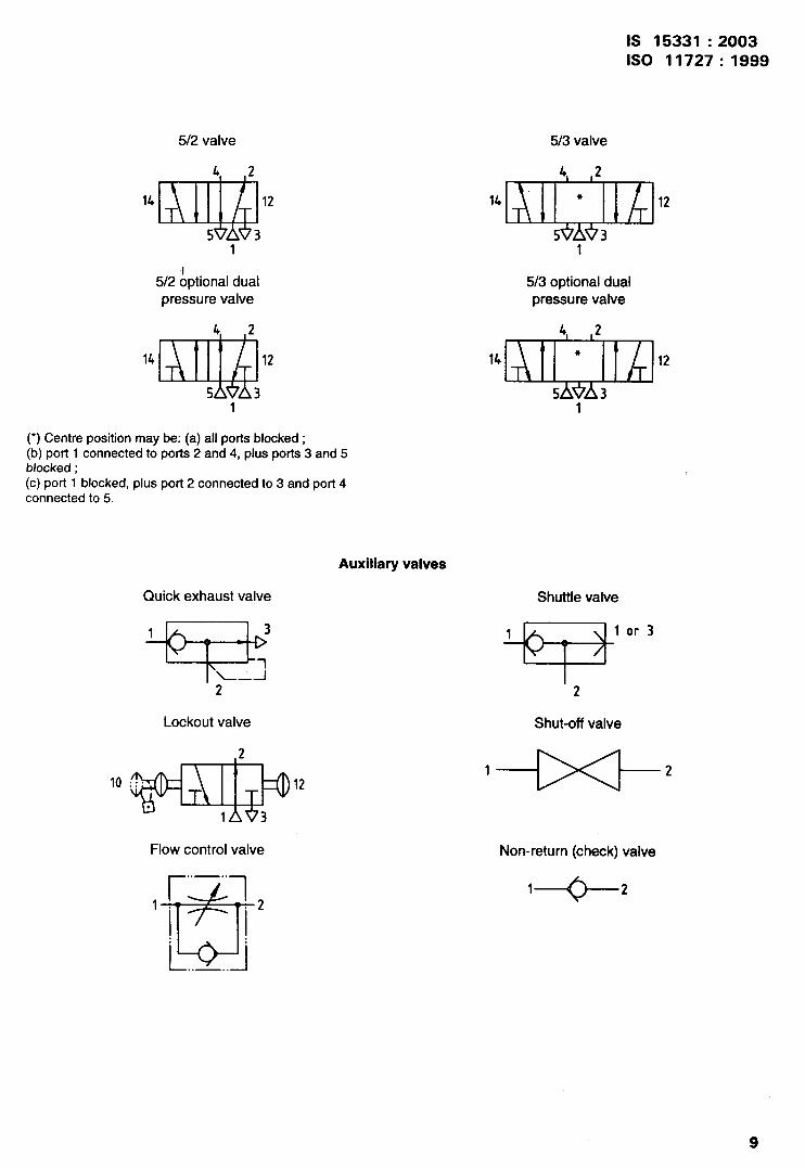
3.165/2 optional dual pressure valve5/2 directional control valve with standard main porl identification, but which is constructed so that the exhaust ports
5 and 3 can be used as separate inlets and the normal inlet port 1, used as a common exhaust port
4 General principles
4.1 The numerals used in this International Standard are the principal means of port identification based on theprecedence established in ISO 5599-1, ISO 5599-2 and ISO 5599-3. Some exceptions are defined for pilot supplyports in valves and for flow direction arrows in two-ported devices.
4.2 Main ports are identified by single-digit numbers.
4.3 Control mechanisms, the pilot control ports and their e~ectrical leads are identified by double-digit numbers.The first of these digits is the number one (1) and the second digit is the main port that communicates with mainport 1 when the correspondingly numbered control mechanism is actuated. If the control mechanism causes mainport 1 to become blocked, a zero (0) is used as the second digit.
NOTE 1 Other flow paths may exist or become blocked as a result of a control mechanism actuation, in addition to the flowpath related to main port 1. These maybe determined from the graphic symbol for the valve. \
NOTE 2 The principle in 4.3, however, does not apply to the centre position of three-position valves or to mechanical/manualcontrol mechanisms that have multiple independent positions.
4.4 Port locations and control mechanism locations are not required to occupy any specific position on acomponent. Their physical location relative to graphic symbols on a drawing also need not correspond.
5 Directional control valves
5.1 Use of single-digit identification numbers
Use the single-digit identification numbers as listed in Table 1 to identify and mark the main ports. Marking shall beplaced next to the ports on the component or on labels that are located to identify the ports.
5.2 Use of two-digit identification numbers
Use the two-digit identification numbers as listed in Table 1 to identify and, if desired, mark the control mechanismsand to identify and mark the pilot control ports (if any exist), plus the solenoid leads (if any exist — see 5.2.1).
3
IS 15331 :2003
ISO 11727:1999
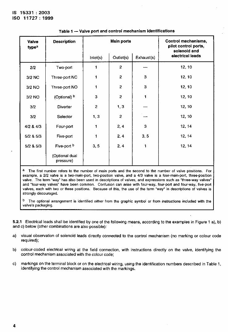
Table 1 — Valve port and control mechanism identifications
Valve Description Main ports Control mechanisms,
types pilot control ports,solenoid and
Inlet(s) Outlet(s) Exhaust(s) electrical leads
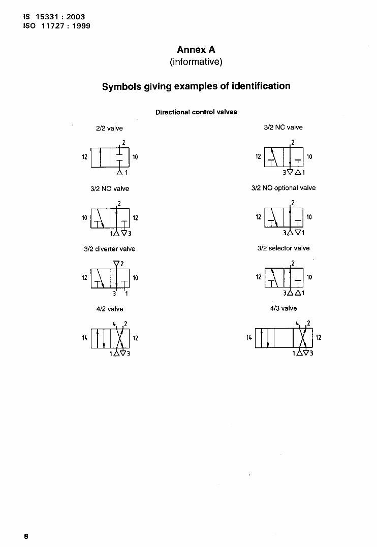
2/2 Two-Porl 1 2 . 12, 10
3/2 NC Three-port NC 1 2 3 12, 10
3/2 NO Three-port NO 1 2 3 12, 10
3/2 NO (Optional) b 3 2 1 12, 10
3/2 Diverter 2 1,3 — 12, 10
3/2 Selector 1,3 2 — 12, 10
.12& 4/3 Four-port 1 2,4 3 12, 14
;/2 & 5/3 Five-port 1 2,4 3,5 12, 14
;12 & 5/3 Five-port b 3,5 2,4 1 12, 14
(Optional dualpressure)
The first number refers to the number of main ports and the second to the number of valve positions. Forample, a 2/2 valve is a two-main-port, two-position valve, and a 4/3 valve is a four-main-port, three-positionIve. The term “way” has also been used in descriptions of valves, and expressions such as “three-way valves”d “four-way valves” have been common. Confusion can arise with four-way, four-pori and four-way, five-portIves, each with two or three positions. Because of this, the use of the term “way” in descriptions of valves is“onglydiscouraged.
The optional arrangement is identified either from the graphic symbol or from instructions included with theIve’s packaging.
5.2.1 Electrical leads shall be identified by one of the following means, according to the examples in Figure 1 a), b)and c) below (other combinations are also possible):
a) visual observation of solenoid leads directly connected to the control mechanism (no marking or colour coderequired);
b) colour-coded electrical wiring at the field connection, with instructions directly on the valve, identifying thecontrol mechanism associated with the colour code;
c) markings on the terminal block or on the electrical wiring, using the identification numbers described in Table 1,identifying the control mechanism associated with the markings.
4
IS 15331 :2003
ISO 11727:1999
r=’=--l
JEILa)
Colour A Co[our A
m
Colour B Co[our B
E
Valve
b)
Valve 12
c)
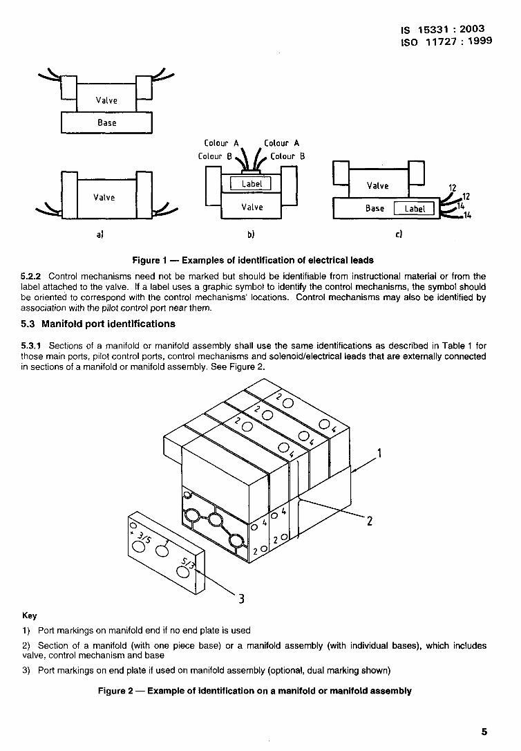
Figure 1 — Examples of identification of electrical leads
5.2.2 Control mechanisms need not be marked but should be identifiable from instructional material or from thelabel attached to the valve. If a label uses a graphic symbol to identify the control mechanisms, the symbol shouldbe oriented to correspond with the control mechanisms’ locations. Control mechanisms may also be identified byassociation with the pilot control port near them.
5.3 Manifold port identifications
5.3.1 Sections of a manifold or manifold assembly shall use the same identifications as described in Table 1 forthose main ports, pilot control ports, control mechanisms and solenoid/electrical leads that are externally connectedin sections of a manifold or manifold assembly. See Figure 2.
Key
1) Port markings on manifold end if no end plate is used
2) Section of a manifold (with one piece base) or a manifold assembly (with individual bases),valve, control mechanism and base
3) Port markings on end plate if used on manifold assembly (optional, dual marking shown)
which includes
Figure 2 — Example of identification on a manifold or manifold assembly
5
IS 15331 :2003
ISO 11727:1999
5.3.2 End plates and/or end surfaces of a manifold or manifold assembly shall use the same identifications asdescribed in Table 1 for main ports and pilot control ports. If main pods have multiple functions or an identificationthat depends upon its assembly location on the manifold ends, then multiple identifications are optional for the ports(see Figure 2).
5.4 External pilot supply port identification
Instructional material shall describe the external pilot supply port application.
5.4.1 Valve designs that allow the use of pilot control ports for the external pilot supply port may use the controlport identifications and describe the arrangements or adjustments necessary in instructional material.
5.4.2 Valves with a separate external pilot supply port, or manifold valves with an external pilot supply port at themanifold end, should use the identifier “X”.
5.5 Pilot exhaust ports identification
Pilot exhaust ports need not be marked.
6 Quick exhaust, shuttle and lockout valves
These devices are essentially 3/2 valves with internal pilot control for quick exhaust and shuttle valves, and withmanual control for lockout valves. Their main ports shall be identified and marked as follows:
Quick exhaust and lockout: inlet port -1
outlet port -2
exhaust port -3
Shuttle: inlet ports -1 and 3; or two ports -1
outlet port -2
7 Shut-off valves
These devices are 2/2 valves and, where the direction of flow is not important for valve functioning, no portidentification and marking is required.
Where the direction of flow is important to the correct functioning of the valve, two options are permitted:
a) the inlet port shall be identified and marked “1” and the outlet port “2”; or
b) instead of numbers, the products maybe marked with an arrow that indicates the direction of flow from the inletport to the outlet port.
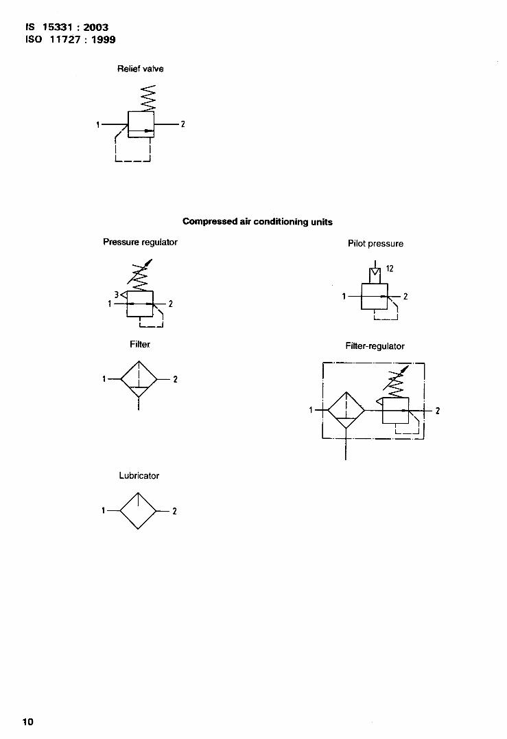
8 Flow control valves, non-return (check) valves and relief valves
These devices are all two-port valves with various control mechanisms. A graphic symbol oriented in the directionof its function and located on the product is preferred. The main ports shall be identified and marked as follows:
— inlet port - 1;
— exhaust or outlet potl -2.
6
Relief valves with an exhaust passage that is not designed for a connection need not have any port markings.
IS 15331 :2003
ISO 11727:1999
9 Pressure regulators and filter-regulators
One of the following options shall be selected for inlet and outlet ports:
a) the inlet port shall be identified and marked “1” and the outlet port as “2”; or
b) instead of numbers, these products may be marked with an arrow to indicate the flow direction from the inlet tothe outlet.
A relief port shall be identified and marked “3”. A relief hole may be identified as “3” but it does not need to bemarked. A pressure regulator with a pilot control shall identify the control pori as “1 2“, but it does not need to bemarked.
10 Filters, lubricators and ancillary units
One of the following options shall be selected for inlet and outlet ports:
a) inlet ports shall be identified and marked “ 1” and outlet ports as “2”; or
b) instead of numbers, these products may be marked with an arrow to indicate flow direction from the inlet to theoutlet.
Drain ports, where they exist, may be identified “L” but do not need to be marked.
11 Examples
Annex A provides symbols (in accordance with ISO 1219-1) that give examples of the identifications defined in thisInternational Standard.
12 Identification statement (Reference to this International Standard)
Use the following statement in test reports, catalogues and sales literature when electing to comply withInternational Standard:
“Ports and control mechanisms of pneumatic control valves and other components identified in accordance withISO 11727:1999, Pneumatic fluid power — Identification of ports and control mechanisms of control valves andother components.”
7
IS 15331 :2003
ISO 11727: 1999
Annex A(informative)
Symbols giving examples of identification
2/2 valve
.2
Directional control valves
3/2 NC valve
,2
12
m
10
Al
3/2 NO valve
L
10Q 12
13
3/2 diverter valve
m2
12 10
31
4/2 valve
42
14
Q
12
13
12
Q
10
31
3/2 NO optional valve
L
12
R!?
10
31
3/2 selector valve
,2
12
w
10
31
4/3 valve
4, ,2
14 II 1A*3
12
8
IS 15331 :2003
ISO 11727:1999
5/2 valve
42
14
m
12
531
5/2 t!ptional dualpressure valve
42
14
m
12
531
(*) Centre position may be: (a) all ports blocked;(b) port 1 connected to ports 2 and 4, plus ports 3 and 5blocked ;(c) port 1 blocked, plus porl 2 connected to 3 and port 4connected to 5.
Auxiliary valves
Quick exhaust valve
%=’1 3
L—12
Lockout valve
Flow control valve
1r-lmL..–..J
‘2
5/3 valve
“*’21
5/3 optional dualpressure valve
“m121
Shuttle valve
-
1 lor3
2
Shut-off valve
+XI-2Non-return (check) valve
l-~-2
9
IS 15331 : 2U03
ISO 11727:1999
Relief valve
4 2
‘f’I iI--J——
Compressed air conditioning units
Pressure regulator Pilot pressure
i---l
Filter
1Q-1 2
Lubricator
1
+
2
10
412
1
)2l—--l
Filter-regulator
r
.—. — .—. — .
1
.—. — .—.
( Contirtuedfrorn second cover)
/nternational Standard Corresponding Indian Standard Degree of Equivalence
ISO 5599-3:1990 Pneumatic fluid IS 15045 ( Part 3 ) :2001 Pneumatic Identical
power — Five-port directional fluid power — Five-port directionalcontrol valves — Part 3 : Code control valves : Part 3 Code systemsystem for communication of valve for communication of valvefunctions functions
For the purpose of deciding whether a particular requirement of this standard is complied with, thefinal value, observed or calculated, expressing the result of a test or analysis shall be rounded off inaccordance with IS 2 : 1960 ‘Rules for rounding off numerical values ( revised )’. The number ofsignificant places retained in the rounded off value should be the same as that of the specified valuein this standard,
Bureau of Indian Standards
BIS is a statutory institution established under the Bureau of Indian Standards Act, 1986 to promoteharmonious developnient of the activities of standardization, marking and quality certification of goods andattending to connected matters in the country.
Copyright
B[S has the copyright of all its publications. No part of these publications maybe reproduced inany form withoutthe prior permission in writing of BIS. This does not preclude the free use, in the course of implementing thestandard, of necessary details, such as symbols and sizes, type or grade designations. Enquiries relating tocopyright be addressed to the Director (Publications), BIS.
Review of Indian Standards
Amendments are issued to standards as the need arises on the basis of comments. Standards are also reviewedperiodically; a standard along with amendments is reaffirmed when such review indicates that no changes areneeded; if the review indicates that changes are needed, it is taken up for revision. Users of Indian Standardsshould ascertain that they are in possession of the latest amendments or edition by referring to the latest issueof ‘B1S Catalogue’ and ‘Standards : Monthly Additions’.
This Indian Standard has been developed from Doc : No. BP 16(0311).
Amendments Issued Since Publication
Amend No. Date of Issue Text Affected
BUREAU OF INDIAN STANDARDS
Headquarters:
Manak Bhavan, 9 Bahadur Shah Zafar Marg, New Delhi 110002Telephones: 23230131,23233375,2323 9402
Regional Offices:
Central: Manak Bhavan, 9 Bahadur Shah Zafar MargNEW DELHI 110002
Eastern: 1/14 C. I. T. Scheme VII M, V. I. P. Road, KankurgachiKOLKATA 700054
Northern: SCO 335-336, Sector 34-A, CHANDIGARH 160022
Southern: C. 1.T. Campus, IV Cross Road, CHENNAI 600113
Western : Manakalaya, E9 MIDC, Marol, Andheri (East)MUMBA1 400093
Telegrams: Manaksanstha( Common to all offices)
Telephone
{
2323761723233841
{23378499,2337856123378626,23379120
{
603843609285
{
22541216,2254144222542519,22542315
{
28329295,2832785828327891,28327892
Branches : AHMEDABAD. BANGALORE. BHOPAL. BHUBANESHWAR. COIMBATORE.FARIDABAD. GHAZIABAD. GUWAHATI. HYDERABAD. JAIPUR. KANPUR.LUCKNOW. NAGPUR. NALAGARH. PATNA. PUNE. RAJKOT. THIRWANANTHAP W.VISAKHAPATNAM.
Printed at New India Printing Press, Khurja, India