Embed Size (px)
Citation preview

Disclosure to Promote the Right To Information
Whereas the Parliament of India has set out to provide a practical regime of right to information for citizens to secure access to information under the control of public authorities, in order to promote transparency and accountability in the working of every public authority, and whereas the attached publication of the Bureau of Indian Standards is of particular interest to the public, particularly disadvantaged communities and those engaged in the pursuit of education and knowledge, the attached public safety standard is made available to promote the timely dissemination of this information in an accurate manner to the public.
इंटरनेट मानक
“!ान $ एक न' भारत का +नम-ण”Satyanarayan Gangaram Pitroda
“Invent a New India Using Knowledge”
“प0रा1 को छोड न' 5 तरफ”Jawaharlal Nehru
“Step Out From the Old to the New”
“जान1 का अ+धकार, जी1 का अ+धकार”Mazdoor Kisan Shakti Sangathan
“The Right to Information, The Right to Live”
“!ान एक ऐसा खजाना > जो कभी च0राया नहB जा सकता है”Bhartṛhari—Nītiśatakam
“Knowledge is such a treasure which cannot be stolen”
“Invent a New India Using Knowledge”
है”ह”ह
IS 2997 (1964): Air circulator type electric fans andregulators [ETD 5: Electric Fans]


IS:2997-1984
Indian Standard SPECIFICATION FOR
AIR CIRCULATOR TYPE ELECTRIC FANS AND REGULATORS
Fifth Reprint MAY 19 97 ( Incorporating Amendments No. 1 to 5 )
UDC 621.313.823.1 : 621.631.4
Q CopVright 1974 BUREAU OF INDIAN STANDARDS MANAK BHAVAN, 9 BAHADUR SHAH ZAFAR MARG
NEW DELHI 110002
Gr6 September 1974
IS:2997-1964
Indian Standard SPECIFICATION FOR
AIR CIRCULATOR TYPE ELECTRIC FANS AND REGULATORS
Electric Fans Sectional Committee, ETDC 5
Chairman
SHRI S. N. MUKERJI
Members
Representing
National Test House, Calcutta
ADDITIONAL CAIEF EN~INEBB Directorate General of Posts 8c Telegraphs ( Ministry of Transport & Communications
DIRECTOR OF TELE~RAPRS (L) ( Alternate ) SHRI A. K. GUPTA ( Alternate )
CDR K. K. BATTA Naval Headquarters LT P. R. PRASAD ( Alternate)
SERI C. L. BLANCEE Eastern Regional Electrical Contractors’ Association ( India ) Ltd, Calcutta
SHRI N. R. SARKAR ( Altermzte) CHIEF ELECTRICAL ENOINEER, Railway Board. ( Ministry of Railways )
NORTHERN RAILWAY SENIOR ELECTRICAL
ENQINEER, N o R T H.E R N RAILWAY ( Altcrnata )
PROF J. K. CHOUDHURY In personal capacity (;7adavpur Universi&, Calcutta ) SERI P. N. DEOBHAKTA Directorate General of Technical Development,
Ministry of Industry SHBI A. N. MUKHERJEE ( Alternate )
SHRI K. P. GAN~ULY Jay Engineering Works Ltd, Calcutta Snnr A. D. NANQIA ( .Iltcmate ) . .
SHRI K. C. GROVER Central Public Works Department
SHRI M. M. KAUL Matchwel Electricals ( India ) Ltd, New Delhi
Snar RAM PRASAD KOTWAL The India Electric Works Ltd, Calcutta
SJXRI J. E. NOBLE Fan Makers’ Association of India, Calcutta
SHRI S. G. PADHYE Crompton Parkinson (Works) Private Ltd, Bombay Snnr R. K. TASKAR ( Altcrnats )
SHRI S. S. RA~HAVAN Engineer-in-Chief’s Branch, Army Headquarters
SHRI U. S. SAVAKOOR Directorate General of Supplies & Disposals SHRI S. R. RAY ( Alternate)
( Cvntinurd on page 2 )
RUmAd “iIF INDI’AN STANDARDS MANAK BHAVAN, 9 BAHADUR SHAH ZAFAR MARG
NEW DELHI 110002

If5 I 2997 - 1964
( Continscd from page I
Members Representing
Saax R. K. TANDAN National Physicnl Laboratory ( CSIR ), New Delhi SHRI Y. S. VENRATEBWARAN, Director, ISI ( Ex-ofi& Member )
Deputy Director ( Electro- technical) ( Secretary )
Panel for Air Circulator Fans, ETDC 5 : PY
Convener
PROP J. K. CH’-PJDEURY
Members
SHXX K. P. GANQULY SERI B. K. MUKHERJEE
In personal capacity (Jadaupur University, Calcutta )
Jay Engineering Works Ltd, Calcutta National Test House, Calcutta
2

Indian Standard SPECIFICATION FOR
AIR CIRCULATOR TYPE ELECTRIC FANS AND REGULATORS
0. FOREWOKD
0.1 This Indian Standard was adopted by the Indian Standards Institution on 25 November 1964, after the draft finalized by the Electric Fans Sectional. Committee had been approved by the Electrotechnical Division Council.
0.2 Like the pedestal type electric fans air circulator fans also are being increasingly used both indoor and outdoor. The main difference between the air circulator type fan and pedestal type fan is that the former has relatively higher air velocities in the axial direction.
0.3 In preparing this specification the general aspects accepted in the IEC publications on electric fans have been adopted.
0.4 This standard is one of a series of Indian Standard Specifications on electric fans. Other specifications published SO far in the series are:
*IS : 374-1960 Electric ceiling fans and regulators (revised) *IS : 555-1960 Electric table type fans and regulators ( reuiscd) *IS : 1169-1957 Pedestal type electric fans
IS : 1709-1960 Fixed capacitors for fans *IS : 2312-19.63 Propeller type ac ventilating fans
0.5 For the purpose of deciding whether a particular requirement of this standard is complied with, the final value, observed or calculated, express- ing the result of a test, shall be rounded off in accordance with IS : 2-19607. The number of significant places retained in the rounded off value should be the same as that of the specified value in this standard.
1. SCOPE
1.1 This standard specifies the requirements and methods of test of air circulator fans, oscillating and non-oscillating, and their associated
*Since revised. tRuies for rounding off numerical values (wised ).
3

IS:2h7-1961
regulators suitable for use on single phase ac circuits and dc circuits not exceeding 250 V, intended for normal domestic and similar uses.
2. TERMINOLOGY
2.9 For the purpose of this standard, the following definitions shall apply.
2.1 Air Circulator Fan -A free air fan having two or more propeller type blades directly driven by an ac or dc electric motor and having rela- tively high air velocities in the axial direction. It may be mounted on a pedestal or a bracket.
2.2 Rating - A statement of the operating characteristics assigned to the fan by the manufacturer when tested in accordance with 19.
2.3 Rated Voltage-The voltage assigned to the fan by the manltfac- turer and marked on it.
2.4 Rated Voltage Range-The voltage limits assigned to the fan by the manufacturer and marked on it.
2.5 Rated Frequency-The frequency assigned to the fan by the manu- facturer and marked on it.
2.6 Rated Frequency Range-The limits of frequency assigned to the fan by the manufacturer and marked on it.
2.7 Rated Spted -The rotational speed specified by the manufacturer at which the fan develops the specified output at the rated frequency.
2.8 Cooling Air Temperature -The temperature of the surrounding atmosphere in which the fan operates.
2.9 Blade Sweep-The diameter of the circle traced out by the extreme tips of the fan blades.
2.10 Size of Fan-The blade sweep in millimetres.
2.11 Plane of Fan Blades-The middle plane of the solid of revolu- tion traced out by the fan blades.
2.12 Plane of Anemometer Vanes -The middle plane of the solid ofrevolution traced out by the vanes of the anemometer.
2.19 Test Plane-The vertical plane containing the plane of the ane- mometer vanes.’ ”
I
2.14 Types of Enclosures of Motors and Regulators 9
2.14.1 Totally Enclosed Type- An enclosure which prevents circula- tion of air between the inside and outside of the case, but not necessarily air-tight.
4

Is r.2997,- 1964
2.14.2 Ventilated Type - An enclosure in which the ventilation is/ not materially obstructed while the live and internal rotating parts are pro- tected mechanically against accidental or careless contact.
2.15 Mounting-The mounting of a fan is the means of attaching the fan system (motor and blades) to its base.
2.16 Insulation
2.16.1 Double Insulation --Denotes insulation comprising both func- tional insulation and supplementary insulation.
2.16.2 Functional Insulation - Denotes insulation necessary for the proper fitnctioning of equipment and for basic protection against electric shock.
2.16.3 Supplementary Insulation ( Protective Insulation ) - Denotes an independent insulation provided in addition to the functional insulation in order to ensure protection against electric shock in case of failure oi the functional insulation.
2.16.4 ReinforLed Insulation - Denotes an improved functional insulation with such mechanical and electric qualities that it provides the same degree of protection against electric shock as double insulation.
2.16.5 Type Tests -Tests ihade on a fan submitted as a sample of that type to prove compliance with the tests which all fans of the type are designed to pais.
2.16.6 Acceptance Tests-Tests made, if required, on fall samples selected from a batch of fans for acceptance.
2.16.7 Routine Tests -Tests made on all fans during manufacture.
3. SIZES, SPEEDS AND TYPES
3.1 The sizes, number of speeds and types of fans shall be as given ill
Table 1.
TABLE 1 SIZES, NUMBER OF SPEEDS AND TYPES
SIZE 01 MIHIXUX TYPE FAN NUMBEB mm or SPEEDY
450 Oscillating or 600 %) Non-oscilla- 750 ting
X~TE- Sizes of’ fans specified above are subject to a tderance off5 dun.
5

IS:2997-1964
4. PREFERRED VOLTAGES
4.1 The preferred voltages for the rating of air circulator type fans shall be 240 and 230 volts.
5. FREQUENCY
5.1 The standard frequency for air circulator fans shall be 50 Hz.
6. NUMBER OF PHASES
6.1 Single phase motors shall be used for ac fans. They may, however, have three phase motors, if required when the preferred voltages will be 400 and 415 volts.
7. TYPE OF MOTORS
7.1 Induction motors (ac) of 450 mm fans shall either be of the shaded pole or capacitor type, but in the case of 600 mm and 750 mm fans they shall be of the capacitor type.
8. DESIGN AND GENERAL CONSTRUCTION
8.1 Stampings -Stampings of ac fans shall be made from electrical steel sheets conforming to IS : 648-1962*.
8.2 Enclosures
8.2.1 Motors and regulators ‘of fans shall be either of the ventilated or totally enclosed type.
8.23 The enclosures of all insulated fans may form part or whole of the supplementary or reinforced insulation.
8.3 Blades-Fans shall be fitted with two or more well-balanced blades made from suitable material. The blades and blade carriers shall be securely fixed so that they do not loosen in operation.
8.4 Guard-Each fan shall have a suitable robust guard either of the open or close mesh type to provide, in normal use, adequate protection against personal injury. When the guards are in two pieces, positive locking arrangement to keep the two pieces together should be made.
8.5 Heat Resistance-No readily flammable material shall be used in the construction of fan and regulator. Moulded parts, if used, shall be of such materials as will withstand the maximum temperature attained in the adjacent component parts.
*Specification for steel sheets for magnetic circuits of power electrical apparatus ( non-oriented steel ) ( reoised ). ( Since revised ).
6

IS : 2997 - 1964 i
8.6 Moisture Resistance - Only suitable material which is resistant to moisture shall be used and the fan shall be capable of withstanding the moisture-proofness test specified in 19.4.
8.7 Bearings - Instructions for the proper lubrication of bearings shall be furnished by the manufacturer.
8.8 Commutator Segments -Commutator segments shall be made from hard-drawn high-conductivity copper and shall have an adequate contact surface for duty involved. 8.9 Carbon Erushes-Carbon brushes for dc air circulator fans shall be of rectangular cross-section. The grade of the brushes used shall be such as would not cause undue wear of commutator or excessive wear of the carbon. Brushes shall be provided with suitable flexible pigtails or tags. Contact between brushes and brush holders shall not be relied upon
: for electrical connection 8.10 Brush Holder Springs -Springs used on carbon brushes shall be of high. quality hard-drawn phosphor-bronze or any other suitable high quality non-rusting metal which will retain its temper in service.
8.11 Supply Cord- Unless specifically agreed otherwise between the supplier and the user, a minimum length of 5 metres of flexible cord of the tough rubber sheathed type or equivalent type [see IS : 434 (Parts I & II)-1964* or IS : 694 (Parts I & II)-196471 suitably connected to the terminals or contacts, shall be supplied with each fan. For fans intended to be earthed, a three-core cable shall be supplied with the earthed core. For fans with double or reinforced insulation, a two-core cord shall be used.
8.11.1 The arrangements of the flexible leads to the fan motor should be such that they will not be damaged as a result of movement in the course of adjustment of the fan height.
8.12 Cord-Grip 8.12.1 Fans shall be provided with a cord-grip capable of passing the
test specified in 19.5.1 SO that the conductors are,‘protected from strain including twisting and abrasion.
8.12.2 The cord-grip shall preferably be of insulating material or, if of metal, be adequately insulated.
8.12.3 On fans with double or reinforced insulation, the cord-grip shall be so designed that the flexible cord does not come into contact with the fixing screws if they are accessible, or in contact with accessible metal
*Specification for rubber insulated cables: Part I Part I!
With copper conductors ( rcaissd). With alufninium conductors ( revised).
$3pe;ay;on f0.r pvc lyulated cables ( for. voltages LIP to 1 100 V ):
Part II 14’1th copper conductors ( rewed ). With aluminiumronductore ( revised).

IS:2997-1964
parts. The cord-grip shall be suitable for the different types of cords which may be attached to the fan.
8.13 Protective Measures -From the point of view of protection against electric shock, electric fans shall be of either of the following two types:
a)
b)
With functional insulation only, with the accessible metal parts designed to be connected to an earthing terminal or contact: and With double or reinforced insulation with the accessible metal parts not designed to be connected to an earthing terminal or contact.
8.13.1 In the case of a fan provided with an earthing terminal or con-
tact, it shall be indelibly marked with the symbol “ & “. The earthing
terminal or contact shall not be used for any other purpose.
8.14 Protection Against Direct Contact - In the assembled fan and regulator, live parts shall not be accessible to the standard test finger (see IS : 1401-1959* ). In the case of a double insulated fan, both func- tionally insulated parts and live parts shall not be accessible to the standard test finger.
8.15 Method of Mounting - The mounting may be of one of the following types:
a) Rigid - The direction of draught is changed only by changing the position of the fan.
b) Semi-rigid - A trunnion and/or swivel arrangement incorporated in the mounting so that the direction of the draught may be
4
d)
altered to suit the requirements. The minimum angle through which it is possible to rotate the fan horizontally as well as vert’- tally without changing the position of the fan shall be 7” vertical y r and 45” horizontally. Orcillating - Some device is provided by which the direction of the axis of the draught is changed automatically and continuously in one plane. Double Oscillating or Gyrostatic - Some device is provided by which the direction of the axis of the draught is changed automatically and continuously in more than one plane. -
8.15.1 Clamping Devices - All clamping devices, where provided shall be of strong and simple design. They shall be so arranged that it is possible to positively adjust the mechanism without there being undue risk of its working loose.
*Specification for accessibiiity test probes. ( Since revised ).
8

IS : 2997 - 1964
8.16 Capacitors - Capacitors (see IS : 1709-1960* ), if any, shall be easily replaceable and placed at sufficient distance from the windings, so that its maximum working temperature is not exceeded. Capacitors shall be clearly marked with the maximum safe working temperature and the corresponding voltage and capacitance.
8.17 Stability - The construction and overall dimensions of the base shall be such as to ensure that the fan is stable with an angle of tilt up to 10” in any direction with fan fully extended.
8.18 Finish - All the surfaces of the assembly and ‘mechanism of both fan and regulator, if any, shall be of corrosion resisting material or shall be suitably and durably protected against corrosion.
8.19 Insulating Material - With the exception of resistance wires in regulators, windings of fans and regulators shall be insulated either with Class A or with Class E insulating materials which comply with limits of temperature-rise specified in 19.3 and moisture-proofness test specified in 19.4 ( for classification of insulating materials, see IS : 1271-1958t ).
9. HEIGHT OF FAN
9.1 Pedestal mounted fans may either be of fixed height type or adjust- able height type.
9.2 Adjustable height type fans shall conform to the heights given in Table 2.
TABLE 2 HEIGHT OF FAN
( Clauses 9.2 und 16.1 )
SIZE ‘OI HEIGHT FAN
-----x7 Min
(1) (2) (3)
mm mm mm
450 1100 1 400 600 1400 1 650 750 1500 1 950
! 9.3 Fixed height type fans shall conform to the minimum heights speci- fied above for the respective sizes.
y
*Specification for fixed capacitors for fans. slassification of insulatmg materials for electrical machinery and apparatus in
relation to their thermal stability in service.
9

IS : 2997 - 1964
10. SPEED REGULATORS
10.1 Regulators shall be capable of reducing the speed of the fan by at least 50 percent of the full speed at the voltage and frequency specified for the test, except in the case of fans of the shaded pole type where the speed reduction shall be not less thti 20 percent. Fans shall be capable of running continuously on any one of the contacts of the regulator at the rated voltage or voltages ( see 2.3 ) or within the whole rated voltage range ( see 2.4 ) whichever is applicable.
10.2 Speed regulators shall be provided with an ‘OFF’ position preferably next to the lowest speed contact and shall be provided with running positions as specified in 3.1. It is desirable that speed steps are equal.
10.3 Where a regulator is provided with a capacitor not permanently connected across the motor terminals, provision shall be made so that the capacitor is discharged when the regulator is in the ‘OFF’ position.
10.4 The regulator handle or knob, if of metal, shall be adequately insulated electrically and thermally.
IO.5 The regulator handle or knob shall be so placed that it can be safely and conveniently manipulated, and unless variable, shall only rest in one of the regulating positions. The handle or knob shall be so designed that it does not become loose in use. The running and ‘OFF’ positions of the regulator shall be distinctly and clearly marked and the indicator on the operating handle or knob shall correctly indicate the position of the regulator.
IO.6 The mechanism of the regulator shall be so designed as to ensure positive contact at each running position. In the case of induction type regulator, it ,is essential that no portion of the induction winding should remain permanently short-circuited in any of the running positions.
IO.7 The regulator shall have mechanical stops for the regulator moving contact to prevent accidental contact with the metallic body of the. regulator in the event of forced overtravel of the knob.
11. STARTING
II.1 The fan shall be capable of starting up from rest with the regulator, if any, at the lowest speed step when 85 percent of the rated voltage or 85 percent of the lowest voltage in the voltage range is applied, with ihe oscillating mechanism in the case of fans of oscillating and double oscil- lating types in action and in the worst position.
12. INTERCHANGEABILITY
12.1 Components of a particular model and size of fan, its associated regulator and set of blades shall be interchangeable.
10
IS : 2997- 1964
13. SILENT OPERATION
13.1 Precautions shall be taken in the manufacture of fans and regulators to ensure a reasonable degree of silence at all speeds.
NOTE-The need for specifying limits of noise levels (acoustical ) of the fans is recognised. However, it has not been found possible to specify theselim its at present on account of:
a) dependency of these limits on the actual location of the fans,
b) lack of data on the acceptable noise levels for different applications, and
c) lack of agreed definition of noise level and method of evaluating the same.
The criterion of noise level may, therefore, be subject to an agreement between the manufacturer and the purchaser.
14. COMMUTATION
14.1 The brush gear of dc fan motor shall be of the fixed-brush type and shall work practically sparklessly and without injury to the surface of the commutator or brushes, within the range of specified speeds.
15. OSCILLATING MECHANISM
15.1 The number of oscillations ( that is, complete to- and fro-cycles ) per minute at full speed shall be not less than four.
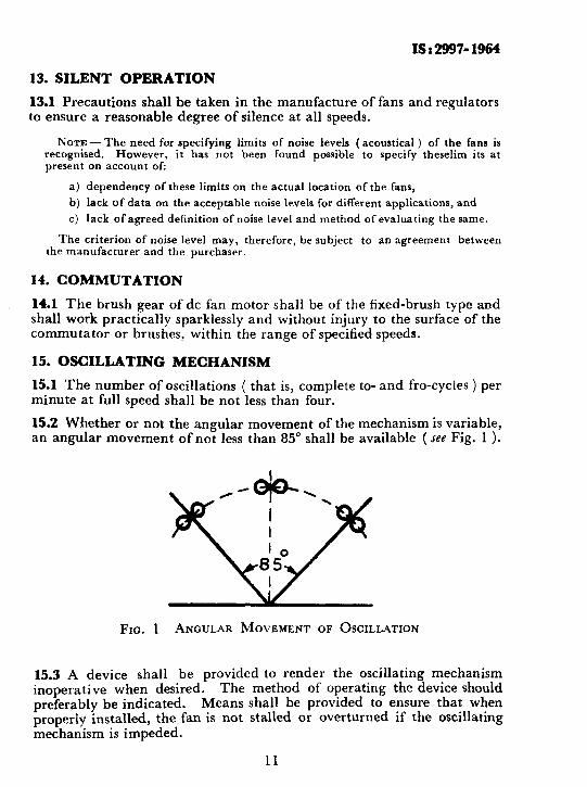
15.2 Whether or not the angular movement of the mechanism is variable, an angular movement of not less than 85” shall be available ( see Fig. 1 1.
FIG. 1 ANGULAR MOVEMENT OF OSCILLATION
15.3 A device shall be provided to render the oscillating mechanism inoperative when desired. The method of operating the device should preferably be indicated. Means shall be provided to ensure that when properly installed, the fan is not stalled or overturned if the oscillating mechanism is impeded.
11

p
IS : 2997 - 1964
16. STANDARD OF PERFORMANCE
16.1 All fans shall be tested by running them at full speed and at rated voltage with the centre of the blades at a height from ground correspond- ing to the minimum height for each size of fan as given in Table 2.
16.2 Minimum Standard of Performance -The minimum air delivery, maximum power input and the minimum peak velocity of the different sizes of fans shall be as given in Table 3 at the test resistance specified in it.
TABLE 3 MINIMUM STANDARD OF PEBFORMANCE
&ZE OS' DISTANCEFBOMTHE FAN PLANEOPFAN BLADES
TOTEEPLANEOF ANE~OMETE~VANE~
(1) (2)
mm mm
450 2 700
600 3 600
750 4 500
MINIMUM TOTAL AIR DELIVERY
(3)
m’/min
125
250
370
MAXIMUM Mnuro~ PSAE POWER hPUT VSLOUlTY
(4) (5)
W m/min
100 245
200 245
250 245
17. TOLERANCES ON RATINGS
17.1 For an air circulator fan covered by this standard, in no case shall the measured performance be inferior to that given in this standard.
17.2 In additon, the observed resuhs expressed as a percentage of the rating assigned by the manufacturer ( scc 2.2 ) shall be within the follow- ing limits:
ChaYucte&ic Tolerance
Electrical input power in watts ( with oscillating mechanism, if provided, in operation )
+ 10 percent
Total air delivery - 10 percent
Fan speed
12

F
ISt299?-1964
18. MARKING
18.1 Each fan shall be indelibly marked with at least the following information:
a) Manufacturer’s name, trade name of fan ( if any ), and number;
b) Country of manufacture;
c) Rated voltage(s) or voltage range and number of phases;
d) Input in watts;
e) Size of fan;
f) Rated speed in revlmin; and
g) Rated frequency.
NOTE-It is recommended that the information mentioned above should also be marked on the associated regulator if it is separate from the fan.
18.1.1 In the case of a fan provided with an earthing terminal or
contact, it shall be indelibly marked with the symbol “ 1 “. -
l9.1.2 For additional information that the manufacturer may be re;quested to supply is listed in Appendix A.
18.:2 BIS Certification Marking
The product may also be marked with Standard Mark.
1&2.1\The use of the Standard Mark is governed by the provisions of/the Bureau of Indian Standards Act, 1986 and the Rules and Regulations made thereunder. The details of conditions under which the licence for the use of Standard Mark may be granted to manufacturers or producers may be obtained from the Bureau of Indian Standards.
19. TESTS
19.1 General - Tests shall be classified as type, acceptance and routine tests. Type tests shall be carried out on three samples. The following are the different tests:
Type Tests
a) Starting ( see 11 ), b) Air Delivery ( see 19.2 ), C) Temperature-Rise ( see 19.3 ), d) Moisture-Proofness ( see 19.4 ), e)- Cord-Grip ( see 19.5 ),
13

f> Mechanical Endurance ( for Regulators Only ) (‘see ~9.6 ),
d Power Factor ( see 19.T),
h) ac Leakage ( see 19.8 ),
3 Oscillating Mechanism ( under consideration ),
k) High Voltage ( see 19.9 ),
4 Insulation Resistance (see 19.10 j,
4 Earthing Continuity ( see 19.11 ),
P) Electrical Input ( see 19.12 ), and
q) Fan Speed ( see 19.13 ).
Acceptance Tests
a) High VoItage,
b) Insulation Resistance,
c) Earthing Continuity,
d) Electrical Input, and
e) Fan speed.
Routine Tests
a) Flash Test ( see 19.14 ), and
b) A simple running test to determine that the fan and oscillating mechanism are in working order; this includes oscillating mecha- nism, if fitted.
19.1.1 Acceptance tests, if requested, shall be made on samples selected according to a method of sampling agreed between the purchaser and the manufacturer.
19.1.2 Limits of Error of Electrical Instruments - The error in the indicated value of ammeters, voltmeters and wattmeters shall not exceed 0.5 per- cent of full scale value for instruments used for type tests. For routine and acceptance tests, industrial class instruments ( see IS : 1248-1958* ) may be used.
19.1.3 Test Voltage - The voltage at which the tests are conducted shall be as follows.
19.1.3.1 When a rated voltage is indicated on the nameplate, the test shall be conducted at the rated voltage. If the fan is specified for two or more distinct rated voltages with three or more supply terminals, the tests shall be carried out at all voltages.
*Specification for electrical indicating instruments. ( Since revised ).
14

IS:2997-1964
19.1.3.2 When a voltage range is indicated on the nameplate, the test voltage shall be as follows:
Sl Test Test Voftuge .No. _-----A-- --7
When the voltage When the voltage range is in excess range is less
of 10 percent than 10 percent of the lowest of the lowest
XX.1 tage voltage I. Temperature-rise Kighest value of 1
range 2. Starting 8.5 of I
the GZZ’value ( of range ( see 1 Mean of the upper 11.1 ) k and lower limits
3. Air delivery and Highest and lowest service value values of range I
4. Power factor and Highest and lowest 1 rated speed values of range J
For a fan with a range of frequency, the test shall be made at the frequency which gives the most unfavourable result.
19.1.3.3 Limits of voltage variation - The variation in the voltage shall not exceed f 1 percent of the test voltage during air delivery tests. While taking the current and watt readings during these tests, however, the voltage shall be the test voltage.
19.2 Air Delivery Test,- The following method for determining the air delivery of the fan shall be followed.
19.2.1 Test Chamber -The fan shall be tested in a test chamber 10 m long, 4.5 m wide and 3 m high; this chamber shall be reasonably free from extraneous draughts while the test is being carried out.
19.2.1.1 The test chamber shall be free from obstructions. Any table or shelf for electrical instruments shall be on the intake side of the fan, beyond a distance of 0’90 m from the plane of the fan blades. No heating or cooling anparatus shall be used in the test room while the test is in progress.
19.2.1.2 The fan shall be so situated that the front of the blades is at least 1.20 m from the back wall and 1’80 m from the side walls.
19.2.2 Testing Instrument-The air movement shall be measured by means of a rotating vane anemometer having an internal diameter of 70 mm suitable for the range of velocities to be measured. It is recom- mended that the anemometer be calibrated frequently.
15

1832997-1964
19.2.3 Arrangement of Apparatus
19.2.3.1 The arrangement of the apparatus ( see Fig. 2 ) shall be such as to permit,Phe anemometer being moved in a horizontal plane containing the axisof the fan, the movement being at right angles to the axis and extendable in both directions. The anemometer shall be supported in such a manner as to offer as little obstruction as possible to the air flow. The axis of anemometer vane shall always be parallel to the axis of the fan blades.
19.2.3.2 The distance between the test plane and the plane of the fan blades shall be in accordance with co1 2 of Table 3.
19.2.4 Procedure for Test
19.2.4.1 Before taking any steps towards testing a fan against this standard, it is essential that it should have been ‘ run-in ’ for at least one hour at the highest voltage of the voltage range.
19.2.4.2 The measurements shall be carried out with the fan running at full speed at the test voltage and with the guard in position.
19.2.4.3 Air ,velocity - Readings shall be commenced at a point 20 mm from the axis of the fan blades, and shall progress along the hori- zontal line in each direction by increments of 40 mm. Readings shall be continued in each direction until the true air velocity falls below 24 metres per minute.
19.2.4.4 Each reading shall consist of the time taken by an air-movement of 300 m measured by the anemometer, except when such air-movement takes more than two minutes; the reading shall then consist of the time taken by a movement of some convenient and readable quantity of air. In no case should the duration of the reading be less than one minute.
19.2.4.5 The average air velocity over any annulus shall be the mean of the readings on either side of the axis of the fan blades at each mean radius of annulus.
19.2.4.6 The average velocity so obtained, multiplied by the area of the corresponding annulus shall be taken as the total air delivery through that annulus.
19.2.4.7 The sum of the air deliveries through all such annuli up to the limit of readings ( see 19.2.4.4 ) shall be taken as the measured air delivery of the fan for the purpose of this standard.
19.2.5 Air conditions ( temperature, relative humidity and pressure ) obtained at the test chamber during tests shall be recorded with the test result.
NOTJG- No correction is to be made until an agreement is available on correc- tion factor.
16


X8:2997-1964
19.3 Temperature-Rise of Fan Motor and Regulator
19.3.1 Permissible Temperature-Rise - The fan motor and regulator shall be tested at any cooling air temperature not exceeding 4o”C, but what- ever be the value of this temperature, the permissible temperature-rise, when measured as described in 19.3.3, shall not exceed the limits given in Table 4.
TABLE 4 PERMISSIBLE LIMITS OF TEMPERATURE-RISE
( c1u1cses 19.3.1 nnd 19.3.3 )
SL PART OP MOTOB TEMPERATURE-RISI~ No. OR REQIJLAT~R ---&____Y
Class A Class E Insulation Insulation
(1) (2) (3) (4) i) Insulated windings of motors 60°C 75°C
ii) Uninsulated parts of motors The temperature-rise shall in no case reach such a value that there is a risk of injury to any insulating material on adjacent parts
iii) Insulated windings, if any, 60°C of regulator (with conti- nuous running on contact )
75°C
iv) Regulator resistance unit (with The temperature-rise shall continuous running on any not reach such a value contact ) that there is a risk of
injury to any insulating material on adjacent parts of the regulator
METHOD OF MEASUREMENT
Change in resistance
Thermometer
Change in resistance
Thermometer
v) External surfaces other than metallic handles, likely to be touched momentarily during normal usage
40°C Thermometer
vi j External surface of capacitors
40% Thermometer
NOTE 1 -Thermocouples, if used, should he applied only to external surfaces which can be reached by an ordinary thermometer.
NOTE 2 -The temperature-rise values given above are for fans normally made to this specification to work in cooling air temperatures not exceeding 40°C. Never- theless, fans made to work in higher cooling air temperatures can be regarded as complying with this specification, provided the temperature-rise values are reduced corresponding to the increase in cooling air temperature. Such fans shall be specially marked.
18

IS 2 2997 - 1964
19.35 Measurement of Cooling-Air Tmfierature D&ng Tests-The cooling-air temperature shall be measured by means of several thermo- meters placed at different points around the fan motor at a distance of one or two metres, and protected from all heat radiations and extraneous draughts. The thermometers used for this test shall be accurate to jz 0.5%.
The value to be adopted for the temperature of the cooling-air during a test shall be the mean of the readings of the thermometers taken at equal intervals of time during the last quarter of the duration of the test.
19.3.3 Measurement of Temperature-Rise - The temperature-rise measurements shall be carried out by the method indicated in Table 4 immediately after the air delivery test or after the fan has been run long enough to ensure that temperature-rise has reached a constant value, using the following procedure.
19.3.3.1 All temperature-rises to be measured by thermometer method [ Items ( ii ), ( iv j, ( v ) and ( vi ) of Table 4 ] shall be taken at the hottest accessible surface of the part, as also on the parts which are likely to cause injury to any adjacent insulating material.
19.3.3.2 The method of measurement of temperature-rise by change in resistance for copper conductors is given below:
The temperature-rise tz - t, may be obtained from the ratio of the resistance by the formula:
t, + 235 R2 -- =- tl + 235 RI
where
RS = resistance of the winding at temperature tz ( “C ) at the end of the test, and
Rt = initial resistance of the winding at temperature tl ( “C j ( cold ).
From the above, the hot temperature ( ts ) may be expressed as:
t2 = -$ ( tl + 235 ) - 235
19.4 Moisture-Proofness Test
19.4.1 The regulator shall be subjected to and shall satisfy the tests specified in 19.9 and 19.10 immediately after having been placed for a period of 24 hours, without passing current through the motor and regulator, in a closed receptacle in which relative humidity is maintained
19

IS :2997 - 1964
at 90-95 percent at any temperature chosen in the range of 40-50°C. Whatever temperature is chosen for this test, it shall be maintained constant to within f 1°C.
19.5 Cord-Grip Test
19.5.1 The flexible cord shall be connected to the fan with the cord- grip in the normal position. The conductors shall be introduced into the terminal and screws, if any, shall be slightly tightened so that the con- ductors cannot easily change their position. After this it shall not be possible to push the cord further into the fan.
The flexible cord shall then be subjected 100 times to a pull of 10 kg for one second. Immediately afterwards, the cord shall be subjected to a torque of 3.5 kg/cm, for a period of one minute. The test shall be made with the flexible cord suitable for the fan and conforming to IS : 434 ( Parts I & II )-1964* or IS : 694 ( Parts I & II )-19647. During the test no damage shall be caused to the flexible cord.
At the end of the test, the cord shaii not have been displaced by more than 2 mm and the ends of the conductors shall not have been noticeably displaced in the terminals.
19.6 Mechanical Endurance Test for Regulator
19.6.1 The regulator shall continue to function satisfactorily after being subjected to a test of 2 500 operations when connected to a fan with locked rotor or an electrical load of equivalent impedance supplied at the maximum rated voltage. One operation includes a full cycle of movement from the ‘ OFF ’ position to the ‘ FULL SPEED ’ position ( or to the other extreme position ) and back to ‘ OFF ‘. The test shall be made at the rate of approximately 6 operations per minute.
19.7 Power Factor Test
19.7.1 The power factor of fan with its associated capacitor, if any, in circuit when tested at the test voltage and the highest speed of the fan shall be not less than 0.90 for capacitor type and 0’50 for non-capacitor type fans.
19.8 ac Leakage Test
19.8.1 The appliance shall be made to rest on .a base well insulated from earth and a single-pole changeover shall be arranged as #shown in
*Specification for rubber insulated cables: Part I With copper conductors ( revised).
Parr II -With alumipium conductors ( ~evtsed).
S %
w:fiICatlon.for pvc insulated cables ( for voltages up to 1 100 V): With copper conductors ( rcvrsed ) .
Part II With aluminium conductors ( rewed).
20

qst2997-1964
Fig. 3 to connect a multirange milliammeter between frame and each live part of the appliance in turn.
NOTE 1 -To avoid risk to the milliammeter a suitable high resistance with a shunting switch may be used in series with the meter. The shunting switch should be kept open to start with and when it is ensued that the meter is safe in both the poaitions of the changeover switch, the shunting switch shall be closed and readings taken.
NOTE 2 -If interference suppression devices are fitted to the appliance they shall be disconnected during the test.
MILLIAMMETER 1
LINE I 4, 0 *
LINE 2 1, I.
1 6
FIG. 3 CONNECTIONS FOR THE MEASUREMENT OF LEAKAGE CURRENT
19.8.1.1 The resistance of the measuring circuit shall be 2 000 f 100 ohms.
19.8.1.2 Care shall be taken that normal earthing connections are not made. It is recommended that the appliance should be supplied through an isolating transformer; otherwise the appliance must be insu- lated from earth.
19.8.1.3 The test shall be made with ac except in the case of appliances for dc only, when dc is used.
19.8.1.4 The milliammeter used to measure the leakage current should have an impedance small in comparison with that of the circuit under test and be of a type not appreciably affected by current wave-forms.
19.9.2 The appliances shall be connected to 1’1 times the rated voltage or to 1’1 times the upper limit of the rated voltage range, and operated as in normal use for a period of at least lominutes. The leakage current. which may flow from any pole of the supply mains to the accessible metal parts and metal foil on external parts of insulating material, connected together, shall be measured under operating conditions.
19.8.2.1 The leakage current shall be measured with the milliammeter connected alternatively to line 1 and line 2.
21

1S : 2997 - 1964
19.8.3 The leakage current for either of the positions (see 19.8.2.1 ) shall not exceed 300 PA ( peak ).
19.9 High Voltage Test
19.9.1 The source of supply for high voltage test shall be not less than 500 VA.
19.9.2 The high voltage test shall be. applied to new and completed fan motors and regulators in normal working conditions with all parts in place except the capacitor which should be disconnected.
19.9.3 An ac test voltage at a frequency of 50 or 60 Hz of approximately sine-wave form shall be applied and maintained for one minute without showing any kind of breakdown or flashover.
The test voltage shall be applied as follows:
a) For fan motors:
1)
2)
3)
4)
Between live parts and body in the case of motors intended to be earthed
Between live parts and other inaccessible metal parts ( that is, over the functional insulation ) in the case of double insulated motors
1 500 volts
1 500 volts
Between the inaccessible metal parts and the body ( that is, over the supplementary insulation ) in the case of double insulated motors
2 500 volts
Between live parts and body ( that is, over the reinforced insulation ) for reinforced insulated motors
4 000 volts
b) For regulators:
1) Between any terminal and the body
2) Between the terminals with the regulator in the ‘ OFF ’ position
1 500 volts
1 500 volts
19.9.4 At the end of one minute, the test voltage shall be removed and the insulation resistance test conducted as in 19.10.
19.10 Insulation Resistance Test i
19.10.1 The insulation resistance test shall he carried out on fans and regulators immediately after conducting the high voltage test ( see lg.9 ).
NOTE - When conducted as a type test for fans and regulators, this test shall fol:ow the moisture-proofness test ( sue 19.4 ).
22

IS : 2997 - 1964
19.10.2 ‘The insulation resistance of the fan motor aud its regulator shall be not less than two megohms when tested after the completion of the bigh voltage test, with a dc voltage of approximately 500 volts applied between points used for the high voltage test.
19.11 Earthing Continuity Test
19.11.1 For fans intended to be earthed, the resistance shall not exceed
0.1 ohm between any exposed metal parts except the rotating parts supported by metal bearings, and
a) the free end if the earthing conductor of the fan is fitted with a flexible cord, due allowance being made for the resistance of the earthing conductor of the flexible cord, or
b) the earthing terminal or contact when the fan is supplied without a flexible cord.
The resistance measurement shall be made with a current of LO A with a dc voltage not exceeding 6 volts.
19.12 Electrical Input Test - The electric power input in watts to the fan shall be determined by running the fan with axis of the blades horizontal at the test voltage specified with the regulator in the highest speed position and with the oscillating mechanism, if any, connected. The oscillating mechanism, shall then be disconnected and the position of the fan fixed so that the direction of the axis of the draught ( that is, the axis of the rotation of the fan blades ) is perpendicular to the test plane. The fan shall then be restarted with the test voltage applied to the terminals and the electrical input in watts again measured. The difference between this and the first reading shall be taken as the power absorbed by the oscillating mechanism.
19.13 Measurement of Fan Speed -The speed of rotarion of‘ the f&n shall be determined by running the fan at the. test voltage and at its rated frequency. The method of measurement shall be such that the speed of the fan is not appreciably affected.
19.14 Flash Test - Every fan and regulator shall withstand the voltage specified in 19.9 for one second, when it is applied instantaneously.
23

APPENDIX A
( CZause 18.1.2 )
ADDITIONAL INFORMATION TO BE SUPPLIED BY THE MANUFACTURER
A-I. The following additional information in respect of an air circulator type electric fan shall be supplied by the manufacturer on request:
a) Power factor,
b) Air delivery,
c) Service value,
d) Number of blades,
e) Type of regulator and number of running positions,
f) Class of insulation,
g) Type of bearings, and
h) Instructions for lubrication of bearings.
24

BUREAU OF INDIAN STANDARDS
Hesdausrters Mar& Bhavan, 9 Bahadur Shah Zafar Marg, NEW DELHI 110002 Telephones: 323 0131,323 3375,323 9402 Fax t 91 11 3234062,91 11 3239399, 91 11 3239362
Central Lsborstory : Plot No. 20/9, Site IV, Sahibabad Industrial Area, Sahibabad 201010
Reglonsl Offices:
Telegrams : Manaksanstha (Common to all Dffices)
Telephone
8-77 00 32
Central : Manak Bhavan, 9 Bahadur Shah Zafar Mug, NEW DELHI 110002 ai* 32 7817
*Eastern : l/l4 CIT Scheme VII M, V.I.P. Road, Maniktola, CALCUTTA 700054 337 86 82
Northern : SC0 335-336, Sector 34-A, CHANDIGARH 160022 60 38 43
Southern : C.I.T. Campus, IV Cross Road, CHENNAI 600113 235 23 15
TWostem : Manakalaya, E9, Behind Mard Tekphone Exchange, Andheri (East), 832 92 95 MtJMBAl4WO93
Brsnch Offices::
‘Pushpak’, Nurmohamed Shaikh Marg, Khanpur, AHMEDABAD 380001
*Peonya Industrial Area, 1 st Stage, Bar-galore-Tumkur Road, BANGALORE 560058
5501346
839 49 56
Gangotri Compkx, 5th Fkwr, Bhadbhada Road, T.T. Nagar, BHOPAL 462003 55 40 21
Plot No. 6283, Unit VI, Ganga Nagar, BHUBANESHWAR 751001 40 36 27
Kalaikathir Buildings. 670 Avinashi Road, COIMBATORE 641037 21 01 41
Plot No. 43, Sector 16 A. Mathura Road, FARIDABAD 121001 8-28 88 01
Savftri Complex. 116 G.T. Rqad, GHAZfABAD 201001 8-71 1996
5315 Ward No.29, R.G. Barua Road, 5th By-laner, GLNVAHATI 781003 541137
5-6-56C, L.N. Gupta Marg, Nampaffy St&on Road, HYDERABAD 500001 201063
E-52, Chitaranjan Marg, C-Scheme, JAIPUR 302901 37 29 25
117/418 B, Sarvodaya Nagar, KANPUR 208065 21 66 76
Seth Bhawan, 2nd Floor, Behind La& Cinema, Naval Kishore Road, 23 8923 LUCKNOW 226001
NIT Building, Second floor, Gokulpat Market NAGPUR 440010 52 5t 71
Patfiputra Industrial Estate, PATNA 800013 26 23 05
Institution of Engineers (India) Building 1332 Shivaji Nagar, PUNE 411005 32 36 35
T.C. No. 14/l 421, lJrhwdy P. 0. Palayam. MIRW ANANTHAPURAM 695034 621 17
*Sales Office is at 5 Chowringhes Approach, P.O. Princsp Street, CALCUTTA 700072
tSalas Cftica is at Novelty Chambers. Grant Road, MUMBAI 400007
*Sales Cffice is at ‘F’ Block, Unity Building, Narashimaraja Square, BANGALORE 560002
271065
309 65 26
222 39 71
Printed at Simco Printing Press. Delhi. India

AMENDMENT NO. 6 FEBRUARY 1994 TO
IS 2997 : 1964 SPECIFICATION FOR AIR CIRCULATOR TYPE ELECTRIC FANS AND REGULATORS
( Clause 16.2 ) - Substitute the following for the existing :
‘16.2 For compliance with requirements of rhis standard, the values of total air delivery shall not be less rhan Ihose spccil’ied in Table 3. In case higher value ol total air delivery is declared by rhe manufacturer, the obsrmcd results, cxprcsscd as the percentage of the values declared by the manufacturer shall not be less than 90 percent of the declared value. The actual input when measured shall not exceed the declared value by more than 10 percent subject IO the condition that the observed value shall in no case exceed the specified value given inTable 3.’
(ETD5) Printed at Simco Printing Press, Delhi, India

AMENDMENT NO. 7 JULY 2000 TO
IS 2997:1964SPEClFHCATIONFORAIRCIRCULATOR TYPEELECTRKFANSANDREGULATORS
( Page 10, ck~rse 10.1, lines 1 and 2 ) - Substitute the following for the existing :
‘at least 30 pcrccnt of the full speed at the voltage and frequency specified’
(Pqe 15, clcr~se 19.2.1 > -Substitute the following for the existing clause:
‘19.1.1 Test Chamber - The fans should be tcstcd in a test chamber 20 m long, IO m wide and 4 m in hcisht. The chamber shall reasonably be free from cxtrancous draughts while the test is being carried out.’
(ETD05) Reprography Unit, MS,-New Deihi, India

AMENDMENT NO. 8 OCTOBER 2002 —*
IS 2997:1964 SPE%FICATION FOR AIR.,,., _u4_..
1!7
7
““?. ‘ .,1 --- -,-- .-—-r -
CIRCULATOR TYPE FANS AND REGULATORS ~— -- -— —.-—.. . +_____ 1 ‘ ‘ ‘
[ Page 14, clause 19.2.1 ( see also Amendment No. 7 ) ] - Substitute the }following for the existing clause:
~..
‘19.2.1 Test Chamber — The fan shall be tested in a test chamber 10 m long,4.5 m wide and 3 m high; this chamber shall be reasonably free from extraneousdraughts while the test is being carried out,’
(ET05)
Reprography Unit, BIS, New Delhi, India
.,