Embed Size (px)
Citation preview

Disclosure to Promote the Right To Information
Whereas the Parliament of India has set out to provide a practical regime of right to information for citizens to secure access to information under the control of public authorities, in order to promote transparency and accountability in the working of every public authority, and whereas the attached publication of the Bureau of Indian Standards is of particular interest to the public, particularly disadvantaged communities and those engaged in the pursuit of education and knowledge, the attached public safety standard is made available to promote the timely dissemination of this information in an accurate manner to the public.
इंटरनेट मानक
“!ान $ एक न' भारत का +नम-ण”Satyanarayan Gangaram Pitroda
“Invent a New India Using Knowledge”
“प0रा1 को छोड न' 5 तरफ”Jawaharlal Nehru
“Step Out From the Old to the New”
“जान1 का अ+धकार, जी1 का अ+धकार”Mazdoor Kisan Shakti Sangathan
“The Right to Information, The Right to Live”
“!ान एक ऐसा खजाना > जो कभी च0राया नहB जा सकता है”Bhartṛhari—Nītiśatakam
“Knowledge is such a treasure which cannot be stolen”
“Invent a New India Using Knowledge”
है”ह”ह
IS 302-2-6 (2009): Safety of household and similarelectrical appliances, Part 2: Particular requirements,Section 6: Cooking Ranges, Hobs, Ovens and SimilarAppliances [ETD 32: Electrical Appliances]


© BIS 2009
B U R E A U O F I N D I A N S T A N D A R D SMANAK BHAVAN, 9 BAHADUR SHAH ZAFAR MARG
NEW DELHI 110002
December 2009 Price Group 8
SU
NS
HIN
E G
RA
PH
ICS
: 2
00
8_
27
IS 302-2-6 : 2009
Hkkjrh; ekud
?kjsyw vkSj leku fo|qr lkfèk=kkas dh lqj{kkHkkx Hkkx Hkkx Hkkx Hkkx 2 fo'ks"k vis{kk,¡ fo'ks"k vis{kk,¡ fo'ks"k vis{kk,¡ fo'ks"k vis{kk,¡ fo'ks"k vis{kk,¡
vuqHkkx vuqHkkx vuqHkkx vuqHkkx vuqHkkx 6 idkus ds js at] idkus dh est vkSj vou rFkk leku lkfèk=k idkus ds js at] idkus dh est vkSj vou rFkk leku lkfèk=k idkus ds js at] idkus dh est vkSj vou rFkk leku lkfèk=k idkus ds js at] idkus dh est vkSj vou rFkk leku lkfèk=k idkus ds js at] idkus dh est vkSj vou rFkk leku lkfèk=k
¼ igyk iqujh{k.k ½
Indian Standard
SAFETY OF HOUSEHOLD AND SIMILARELECTRICAL APPLIANCES
PART 2 PARTICULAR REQUIREMENTS
Section 6 Cooking Ranges, Hobs, Ovens and Similar Appliances
( First Revision )
ICS 97.040.20; 13.020

Electrical Appliances Sectional Committee, ETD 32
FOREWORD
This Indian Standard (Part 2/Sec 6) (First Revision) was adopted by the Bureau of Indian Standards, after thedraft finalized by the Electrical Appliances Sectional Committee had been approved by the ElectrotechnicalDivision Council.
This standard was first published in 1993. This revision has been undertaken primarily to align the existing standardwith corresponding latest International Standard and also to align with the revised version of Part 1 of this standard.
This standard covers the safety requirements of stationary cooking ranges, hobs, ovens and similar appliances,electric washing machines for household and similar use.
This standard does not cover the performance requirements. However, performance requirements of domesticelectric cooking ovens are covered under a separate standard IS 5790 : 1985 ‘Domestic electric cooking ovens(first revision)’ and single walled baking ovens are covered in IS 8985 : 1978 ‘Single walled baking ovens’.
It has been assumed in the formulation of this standard that the execution of its provisions is entrusted toappropriately qualified and experienced persons.
This standard recognizes the internationally accepted level of protection against hazards such as electrical,mechanical, thermal, fire and radiation of appliances when operated as in normal use taking into account themanufacturer’s instructions. It also covers abnormal situations that can be expected in practice and takes intoaccount the way in which electromagnetic phenomena can affect the safe operation of appliances.
This standard takes into account the requirements of IS 732 : 1989 ‘Code of practice for electrical wiringinstallations (third revision)’ and SP 30 : 1985 ‘National electrical code’ as far as possible so that there iscompatibility with the wiring rules when the appliance is connected to the supply mains. However, nationalwiring rules may differ.
If an appliance within the scope of this standard also incorporates functions that are covered by another Part 2 ofIS 302, the relevant Part 2 is applied to each function separately, as far as is reasonable. If applicable, the influenceof one function on the other is taken into account.
This standard is a product family standard dealing with the safety of appliances and takes precedence overhorizontal and generic standards covering the same subject.
An appliance that complies with the text of this standard will not necessarily be considered to comply with thesafety principles of the standard if, when examined and tested, it is found to have other features that impair thelevel of safety covered by these requirements.
An appliance employing materials or having forms of construction differing from those detailed in the requirementsof this standard may be examined and tested according to the intent of the requirements and, if found to besubstantially equivalent, may be considered to comply with the standard.
This standard is to be read in conjunction with IS 302-1 (2008) ‘Safety of household and similar electricalappliances: Part 1 General requirements’. For the sake of convenience, the clauses of this standard correspond tothose of IS 302-1(2008), instead of reproducing full text of each clause, clauses of IS 302-1(2008) which areapplicable (which means that relevant provisions of the clause apply) or not applicable and the subclauses orportion thereof which are not applicable are indicated as under:
a) In case of a clause where it is applicable, the wording used is ‘This clause of IS 302-1 (2008) is applicable/not applicable’; and
b) In case of a subclause or part thereof ‘Not applicable’.
(Continued on third cover)

Wherever a subclause of IS 302-1 (2008) is to be replaced by a new text, it has been indicated as under:
Replacement or Modification – followed by the new text.
Any addition to the existing provision of a subclause of IS 302-1 (2008) has been indicated as under:
Addition — followed by the text of the additional matter.
Clauses/Tables which are additional to those of IS 302-1 (2008) are numbered starting from 101 and additionalsubclauses are numbered with the main clause number followed by 101, 102, etc, for example, 7.101.
Should, however, any deviation exist between IS 302-1 (2008) and this standard, the provisions of the latter shallapply.
This standard is based on IEC 60335-2-6 (2004) ‘Safety of household and similar electrical appliances — Part 2-6:Particular requirements for stationary cooking ranges, hobs, ovens and similar appliances’ issued by theInternational Electrotechnical Commission except for the following modification:
a) The leakage current value is more stringent as compared to IEC Publication,b) Ambient test conditions are based on National conditions, and
c) Schedule of type and acceptance test added.Following changes have been incorporated in this revision:
a) Additional requirements in 7.12 on marking and instruction included,b) Transient overvoltage (see 14) test added,
c) Additional test for mechanical test added (see 21.1), andd) Additional requirements added in 22 (see 22.120 and 22.121).
For the purpose of deciding whether a particular requirement of this standard is complied with, the final value,observed or calculated, expressing the result of a test, shall be rounded off in accordance with IS 2 : 1960 ‘Rulesfor rounding off numerical values (revised)’. The number of significant places retained in the rounded off valueshould be the same as that of the specified value in this standard.
(Continued from second cover)

1
IS 302-2-6 : 2009
Indian Standard
SAFETY OF HOUSEHOLD AND SIMILARELECTRICAL APPLIANCES
PART 2 PARTICULAR REQUIREMENTS
Section 6 Cooking Ranges, Hobs, Ovens and Similar Appliances
( First Revision )
1 SCOPE
This clause of Part 1 is replaced by the following:
This standard deals with the safety of electriccooking ranges, hobs, ovens and similar appliancesfor household use, their rated voltage being not morethan 250 V for single-phase appliances connectedbetween one phase and neutral, and 480 V for otherappliances.
NOTE 101 — Examples of appliances that are within the scopeof this standard are:
a) griddles,
b) grills,
c) induction hobs,
d) pyrolytic self-cleaning ovens, and
e) steam ovens.
As far as is practicable, this standard deals withthe common hazards presented by appliances thatare encountered by all persons in and around thehome. However, in general, it does not take intoaccount:
a) the use of appliances by young children orinfirm persons without supervision, and
b) playing with the appliance by young children.
NOTE 102 — Attention is drawn to the fact that:
a) for appliances intended to be used in vehicles or on boardships or aircraft, additional requirements may be necessary;and
b) in many countries additional requirements are specifiedby the national health authorities, the national authoritiesresponsible for the protection of labour, the national watersupply authorities and similar authorities.
NOTE 103 — This standard does not apply to:
a) appliances intended for commercial catering,
b) appliances intended to be used in locations where specialconditions prevail, such as the presence of a corrosive orexplosive atmosphere (dust, vapour or gas),
c) grills, toasters and similar portable cooking appliances(IS 302-2-9), and
d) microwave ovens (IS 302-2-35).
2 REFERENCES
This clause of Part 1 is applicable except as follows:
Addition
IS No. TitleIS/IEC 60584-1 Thermocouples — Part 1: Reference
tables
3 TERMINOLOGY
This clause of Part 1 is applicable except as follows:
3.1.6 Addition
NOTE 101 — For appliances having more than three heatingunits per phase, a diversity factor is applied to the rated currentor rated power input when determining the current used toestablish the size of the terminals and the nominal cross-sectional area of the supply cord. The diversity factor F iscalculated from the following formula, where N is the numberof heating units per phase that can be energized together:
0.650.35F
N= +
3.1.9 Replacement
Normal Operation — Operation of the appliance asspecified in 3.1.9.101 to 3.1.9.107.
3.1.9.101 Hob elements, other than induction hobelements, are operated with vessels containing coldwater. The vessel is made of unpolished commercialquality aluminium, has a flat bottom and is coveredwith a lid. Thermal controls are adjusted to their highestsetting until the water boils and then adjusted so thatthe water boils gently. Water is added to maintain thelevel during boiling.
NOTE 1 — The lid is positioned so that steam does not affectthe test.
In case of doubt, vessels as specified in Fig. 101 areused.
Induction hob elements are operated with vessels asspecified in Fig. 102 that contain approximately halftheir capacity of cooking oil at room temperature.

2
IS 302-2-6 : 2009
Thermal controls are adjusted to their highest settinguntil the oil temperature reaches 180°C ± 4°C and thenadjusted so that this temperature is maintained.
For all hob elements the diameter of the bottom of thevessel is approximately equal to the diameter of thecooking zone and the quantity of liquid is specified inTable 101. The vessel is positioned centrally on thecooking zone.
NOTE 2 — If several cooking zones are marked for one hobelement, the most unfavourable zone is used for the test.
NOTE 3 — For non-circular cooking zones, the smallest non-circular vessel is used which will cover the cooking zone asfar as possible, taking into account the hob rim and the othervessels. The quantity of liquid is determined on the basis ofthe minor diameter of the cooking zone.
3.1.9.102 Ovens are operated empty with the doorclosed. Thermal controls are adjusted so that the meantemperature in the centre of the oven is maintained at:
a) 220°C ± 4°C for ovens with forced aircirculation, and
b) 240°C ± 4°C for other ovens.
c
2
b
∅a
IEC 805/02
All dimensions in millimetres.
Approximate Dimension
Diameter of Cooking Zone
a b c
≤ 110 110 140 8
>110 ≤145 145 140 8
>145 ≤180 180 140 9
>180 ≤220 220 120 10
>220 ≤300 300 100 10
NOTE — The maximum concavity of the base of the vessel is to be not more than 0.05 mm. The base of the vessel is not to be convex.
FIG. 101 VESSEL FOR TESTING HOB ELEMENTS
A
C
dIEC 806/02
KeyA = base and wall thickness, 2 mm ± 0.5 mmC = maximum concavityd = diameter of the flat area of the base
NOTE — The vessel is made of low carbon steel having a maximum carbon content of 0.08 percent. It is cylindrical without metallichandles or protrusions. The diameter of the flat area of the base of the vessel is to be at least the diameter of the cooking zone. Themaximum concavity of the base of the vessel is 0.006 d. The base of the vessel is not to be convex.
FIG. 102 VESSEL FOR TESTING INDUCTION HOB ELEMENTS

3
IS 302-2-6 : 2009
NOTE — If the temperature cannot be attained, the thermalcontrol is adjusted to its highest setting.
Ovens without thermal controls are switched on andoff so that the temperature in the centre of the oven ismaintained at 240°C ± 15°C.
Steam ovens are operated in accordance with theinstructions. Controls are adjusted to their highestsetting until the cooking temperature is reached andthen adjusted to the lowest setting that maintains thistemperature.
Steam generators intended to be filled by hand are filledaccording to the instructions, water being added tomaintain the steam generation.
Steam generators intended to be filled automaticallyare connected to a water supply, the pressure of whichis set according to the instructions.
The supply water has a temperature of:
a) 15°C ± 5°C for appliances to be connected toa cold water supply; and
b) 60°C ± 5°C or the temperature indicated inthe instructions, whichever is the higher, forappliances to be connected to a hot watersupply.
Steam ovens are also operated while generating steambut with the thermal controls adjusted as for operationwithout steam.
3.1.9.103 Grills are operated empty with the grill panand food supports in the most unfavourable positionfor normal use, the door and any other accessoriesbeing positioned in accordance with the instructions.In the absence of such instructions, the door and otheraccessories are placed in the most unfavourableposition in which they may be left. Thermal controlsare adjusted to their highest setting. However, if theinstructions for grills incorporated in ovens specify alower setting, this setting is used. Any reflectorsintended to be placed above heating elements are inposition.
3.1.9.104 Rotating spits in ovens or grills are operated
with the load on the rotating spit as shown in Fig. 103.The appliance is operated taking into account theinstructions with regard to:
a) the heating elements to be operated,
b) the setting of the thermal control, andc) the position of the door and grill pan.
In the absence of such instructions, the control isadjusted to its highest setting and the door is fully openor is placed in the most unfavourable intermediateposition in which it may be left.
Any grill pan is placed in its lowest position.
3.1.9.105 Warming drawers and similar compartmentsare operated in the closed position with their controlsadjusted to the highest setting.
3.1.9.106 Griddles are operated so that the temperatureat the centre of the heated surface is maintained at275°C ± 15°C by adjusting their thermal controls orby switching the supply on or off.
3.1.9.107 Cooking ranges are operated with theirindividual heating units being operated under theirstated conditions of normal operation.
3.101 Oven— Appliance having a heated cavity witha door and constructed so that food, which may be in acontainer, can be placed on a shelf.
3.102 Grill — Heating unit constructed so that the foodis supported on a grid or spit and is cooked by radiantheat.
NOTE — The cooking operation in a grill is known as grillingor broiling.
3.103 Hob— Appliance that incorporates a hobsurface and one or more hob elements, and is built inor part of a cooking range.
3.104 Cooking Range— Appliance incorporating ahob and an oven and which may incorporate a grill orgriddle.
3.105 Pyrolytic Self-Cleaning Oven— Oven inwhich cooking deposits are removed by heating theoven to a temperature exceeding 350°C.
Table 101 Quantity of Liquid in the Vessel(Clause 3.1.9.101)
Sl No.
Diameter of Cooking Zone
mm
Quantity of Water or Oil
l
(1) (2) (3)
i) ≤ 110 0.6 ii) > 110 and ≤ 145 1.0 iii) > 145 and ≤ 180 1.5 iv) > 180 and ≤ 220 2.0 v) > 220 and ≤ 300 3.0

4
IS 302-2-6 : 2009
3.106 Steam Oven — Oven intended for cooking foodby steam generated at atmospheric pressure in theappliance.
3.107 Griddle — Heating unit having a surface onwhich the food is placed directly for cooking.
3.108 Induction Hob — Hob containing at least oneinduction hob element.
3.109 Heating Unit — Any part of the appliance thatfulfils an independent cooking or warming function.
NOTE — Examples are hob elements, ovens, grills andwarming drawers.
3.110 Hob Surface — Horizontal part of the applianceon which vessels can be placed.
3.111 Hob Element — Heating unit attached to thehob surface or positioned below the cooking zone.
A
∅100+2 0
85+1 0
6 0–1
20 0–1
C D
B
IEC 804/02
Key
A = load, mass approximately 4.5 kg C = axis of loadB = fixing screw D = axis of fixing screw
NOTE — The load is positioned on the rotary spit so that the fixing screw contacts the diameter of the spit.
All dimensions in millimetres.
FIG. 103 LOAD FOR TESTING ROTATING SPITS

5
IS 302-2-6 : 2009
3.112 Induction Hob Element — Hob element thatheats metallic vessels by means of eddy currents.
NOTE — The eddy currents are induced in the bottom of thevessel by the electromagnetic field of a coil.
3.113 Pan Detector — Device incorporated in a hobelement that prevents its operation unless a vessel isplaced on the cooking zone.
3.114 Cooking Zone — Area marked on a hob surfacewhere the vessel is placed for heating food.
NOTE — When a hob element protrudes above the hob surface,its surface is the cooking zone.
3.115 Touch Control — Control actuated by contactor proximity of a finger, with little or no movement ofthe contact surface.
3.116 Temperature-Sensing Probe — Device that isinserted into the food to measure its temperature andwhich is a part of an oven control.
3.117 Rated Water Pressure — Water pressureassigned to the appliance by the manufacturer.
4 GENERAL REQUIREMENTS
This clause of Part 1 is applicable.
5 GENERAL CONDITIONS FOR THE TESTS
This clause of Part 1 is applicable except as follows:
5.3 Addition
For pyrolytic self-cleaning ovens, the tests of 22.108to 22.111 are carried out before the tests of 19.
5.4 Addition
Appliances that also use gas are supplied with gas atthe appropriate rated pressure. Vessels having adiameter of approximately 220 mm are filled with2 litres of water, covered with a lid and placed on thehob burners. The controls are adjusted to their highestsetting until the water boils. They are then adjusted sothat the water simmers, water being added whennecessary to maintain the level.
5.101 Class III temperature-sensing probes are onlysubjected to the tests of 19.
6 CLASSIFICATION
This clause of Part 1 is applicable except as follows:
6.1 Modification
Appliances shall be class I, class II or class III.
7 MARKING AND INSTRUCTIONS
This clause of Part 1 is applicable except as follows:
7.1 Addition
The total rated power input or rated current of inductionhob elements shall be marked.
If a cooking range incorporates a socket-outletprotected by means of fuses, other than D type fuses,it shall be marked with the rated current of the relevantfuse. When a miniature fuse-link is provided, thismarking shall indicate that the fuse-link is to have ahigh breaking capacity.
7.6 Addition
ON/OFF (push-push)
7.10 Addition
The off position of touch controls for hobs shall bemarked by the Fig. O and the on position by the Fig. I.If there is no touch control for the hob, this requirementapplies to the touch controls for each hob element.
NOTE 101— If the same touch control is used for switchingon and off, symbol as given in 7.6 may be used.
7.12 Addition
If the hob surface is of glass-ceramic or similar materialand protects live parts, the instructions shall includethe substance of the following:
WARNING — If the surface is cracked, switch off the applianceto avoid the possibility of electric shock.
The instructions for cooking ranges and ovens shallinclude the substance of the following:
‘During use the appliance becomes hot. Care shouldbe taken to avoid touching heating elements inside theoven’.
The instructions for ovens shall state the substance ofthe following:
WARNING — Accessible parts may become hot during use.Young children should be kept away.
The instructions for ovens having doors with glasspanels shall include the substance of the following:
Do not use harsh abrasive cleaners or sharp metalscrapers to clean the oven door glass since they canscratch the surface, which may result in shattering ofthe glass.
If during the test of 11, the temperature rise at the centreof the internal bottom surface of a storage drawerexceeds that specified for handles held for short periodsin normal use, the instructions shall state that thesesurfaces can get hot.
The instructions for pyrolytic self-cleaning ovens shallstate that excess spillage shall be removed before

6
IS 302-2-6 : 2009
cleaning and shall specify which utensils can be left inthe oven during cleaning.
If, for cleaning, the manufacturer instructs the user toset the controls to a position higher than for normalcooking purposes, the instructions shall state that undersuch conditions the surfaces may get hotter than usualand children should be kept away.
The instructions for ovens incorporating a fan with aguard that can be removed for cleaning shall state thatthe oven shall be switched off before removing theguard and that, after cleaning, the guard shall bereplaced in accordance with the instructions.
The instructions for ovens provided with a facility touse a temperature-sensing probe shall include thesubstance of the following:
‘Only use the temperature probe recommended for thisoven’.
The instructions for cooking ranges, hobs and ovensshall state that a steam cleaner is not to be used.
The instructions for induction hobs shall include thesubstance of the following:
‘Metallic objects such as knives, forks, spoons and lidsshould not be placed on the hob surface since they canget hot’.
The instructions for hobs incorporating a lid shall statethat any spillage should be removed from the lid beforeopening. They shall also state that the hob surfaceshould be allowed to cool before closing the lid.
The instructions for hobs incorporating halogen lampsshall warn the user not to stare at the hob elements.
The instructions for hobs incorporating a pan detectorshall include the substance of the following:
‘After use, switch off the hob element by its controland do not rely on the pan detector.’
If the appliance incorporates a lamp for illumination,and does not incorporate a switch providing fulldisconnection under overvoltage category IIIconditions, the instructions shall include the substanceof the following:
WARNING — Ensure that the appliance is switched off beforereplacing the lamp to avoid the possibility of electric shock.
7.12.1 Addition
The installation instructions for cooking ranges thatare placed on the floor shall state that if the range isplaced on a base, measures have to be taken to preventthe appliance slipping from the base.
NOTE 101 —This statement is not required if the instructionsspecify that the range should not be placed on a base.
The installation instructions for appliances intendedto be connected to the water mains shall include themaximum rated water pressure in megapascals.
7.12.3 Addition
If a cooking range does not have a supply cord, theinstructions shall state the type of cord to be used,taking into account the temperature of the rear surfaceof the appliance.
7.12.4 Addition
The instructions for built-in appliances having separatecontrol panels shall state that the control panel is onlyto be connected to the heating units specified in orderto avoid a possible hazard.
7.15 Addition
When it is not practical for the marking of fixedappliances to be visible after the appliance has beeninstalled, the relevant information shall be included inthe instructions or on an additional label that can befixed near the appliance after installation.
NOTE 101 —An example of such an appliance is a built-in hob.
The marking for the rated current of the fuse protecting asocket-outlet shall be placed on or near the socket-outlet.
7.101 Steam generators intended to be filled manuallyshall be marked with the maximum water level, whichshall be visible during filling.
Compliance is checked by inspection.
7.102 The cooking zone of hob surfaces shall beidentified by appropriate marking unless it is obvious.
Compliance is checked by inspection.
7.103 BIS Certification Marking
The appliances may also be marked with the StandardMark.
7.103.1 The use of the Standard Mark is governed bythe provisions of the Bureau of Indian Standards Act,1986 and the Rules and Regulations made thereunder.The details of conditions under which the licence forthe use of the Standard Mark may be granted tomanufacturers or producers may be obtained from theBureau of Indian Standards.
8 PROTECTION AGAINST ACCESS TO LIVEPARTS
This clause of Part 1 is applicable except as follows:
8.1.2 Addition
Test probe 12 of IS 1401 is applied without appreciableforce to parts liable to be touched accidentally innormal use by a fork or similar pointed object. It shallnot be possible to touch live parts.

7
IS 302-2-6 : 2009
8.1.3 Modification
The use of test probe 41 instead of test probe B andtest probe 13 is only allowed when visibly glowingheating elements are situated at the top of an oven orgrilling compartment.
9 STARTING OF MOTOR-OPERATEDAPPLIANCES
This clause of Part 1 is not applicable.
10 POWER INPUT AND CURRENT
This clause of Part 1 is applicable except as follows:
10.1 Addition
The power input of induction hob elements is measuredseparately and the tolerances for motor-operatedappliances apply.
The contribution of a socket-outlet to the power inputis considered to be 1 kW.
NOTE 101 —Socket-outlets are not loaded during the test.
10.2 Addition
The current of induction hob elements is measuredseparately and the tolerances for motor-operatedappliances apply.
The contribution of a socket-outlet to the current isconsidered to be 1 kW divided by the rated voltage.
NOTE 101 —Socket-outlets are not loaded during the test.
11 HEATING
This clause of Part 1 is applicable except as follows:
11.1 Addition
For cooking ranges and ovens, compliance is alsochecked by the test of 11.101.
11.2 Addition
For appliances intended to stand on the floor, a closedrectangular box is placed as close as possible to thefree side of the appliance and against the rear wall ofthe test corner. The box is made of dull black paintedplywood 10 mm thick. It has a width of 150 mm, itstop being level with the hob surface and its front flushwith the front surface of the appliance.
Appliances having a lid to cover the hob surface aretested with the lid open. Lids that can be removedwithout the aid of a tool are removed, unless the hobelement cannot operate with the lid removed.
Temperature-sensing probes are placed in the oven inany position likely to occur during normal use. Theyare not connected to control the oven temperature. The
test for pyrolytic self-cleaning ovens is carried out withtemperature-sensing probes in position, unlessotherwise specified in the instructions.
Detachable parts that are intended to be used to reducethe temperature of control panels are removed.
NOTE 101 —A retractable part is not considered to be adetachable part.
11.3 Addition
The temperature of the centre of the oven and thetemperature rises of the surface of the rectangular boxare determined using the thermocouples specified forthe walls of the test corner.
NOTE 101 —If the magnetic field of an induction hob elementunduly influences the results, the temperature rises can bedetermined using platinum resistances with twisted connectingwires or any equivalent means.
11.4 Addition
Induction hob elements are supplied separately andoperated as specified for motor-operated appliances.
Cooking ranges are operated at 1.15 rated power inputunder normal operation. The supply voltage ismeasured when the power input has stabilized. Thisvoltage is used to supply the heating units of thecooking range during the tests.
11.6 Replacement
Combined appliances are operated as specified forheating appliances.
If the temperature rise limits are exceeded in appliancesincorporating motors, transformers or electroniccircuits, and the power input is lower than the ratedpower input, the test is repeated with the appliancesupplied at 1.06 times rated voltage.
11.7 Replacement
Appliances are operated for the duration specifiedin 11.7.101 to 11.7.106.
NOTE 101 — Steady conditions are considered to be establishedif the temperature does not rise by more than 1 K in 15 min.
11.7.101 Induction hob elements are operated for30 min. Other hob elements are operated for 60 min.
11.7.102 Ovens are operated for 60 min. If a rotatingspit is provided, it is in operation.
NOTES
1 Steam ovens are operated in each mode of operation.
2 Lamps in ovens are not manually switched on.
If an appliance incorporates two ovens that can beenergized simultaneously, they are tested together.
Pyrolytic self-cleaning ovens are also operated under

8
IS 302-2-6 : 2009
the cleaning conditions specified in the instructions forthe maximum time allowed by the control or untilsteady conditions are established, whichever is shorter.During this period, other heating units that can beenergized are operated under normal operation.
11.7.103 Grills are operated for 30 min. However, grillshaving means to reduce the power input are operatedfor 15 min with their controls adjusted to the highestsetting and then for 15 min at a setting which reducesthe average power input by approximately 50 percent.
Grills provided with a rotating spit are also operatedwith the spit rotating for 60 min.
11.7.104 Griddles incorporating a thermal control areoperated until steady conditions are established. Othergriddles are operated for 30 min after the centre of theheating surface attains a temperature of 275°C.
11.7.105 Warming drawers and similar compartmentsare operated for 30 min.
11.7.106 For cooking ranges, combinations of heatingunits that can be energized simultaneously are testedtogether for the durations specified in 11.7.101to 11.7.105, heating units that have a test duration of30 min being operated for the last 30 min of the test.
NOTE— For example, the sequence of tests for a cooking rangeincorporating a grill in the oven and a rotating spit is as follows:
a) Operation of the hob and oven and, if possible, with thespit rotating, for 60 min;
b) Cooling down to approximately room temperature;
c) Operation of the hob for 60 min, the grill being operatedsimultaneously for the last 30 min;
d) Cooling down to approximately room temperature; and
e) Operation of the hob and grill with the spit rotating, for60 min.
11.7.107 If the appliance incorporates a socket-outlet,an appropriate plug complying with IS 1293 is engaged.The plug is connected to a 1 kW resistive load by meansof an ordinary polyvinyl chloride sheathed flexible cordas per IS 694 having a cross-sectional area of 0.75 mm2.The temperature rise of the plug is determined duringthe last 30 min of the test.
11.8 Modification
Instead of the temperature rises stated in Table 3 forwood, the following applies.
Temperature rises of the floor and walls of the testcorner, wooden cabinets and the rectangular box shallnot exceed the following values:
a) Appliances intended to stand on a table 65 K
b) Grills 75 Kc) Other appliances 70 K
The temperature rise of parts of the underside of built-in hobs, accessible to a 75 mm diameter probe havinga hemispherical end, shall not exceed 70 K unless theinstructions specify that a board is to be installedunderneath the hob.
Addition
The temperature rise of handles of inner glass doors,grill pans, temperature-sensing probes and rotatingparts in ovens or grills is not limited.
During the additional test for pyrolytic self-cleaningovens, the temperature rise of the surface of knobs,handles and levers shall not exceed the followingvalues:
a) Metal 55 K
b) Porcelain or vitreous material 65 K
c) Moulded material, rubber or wood 80 K
The temperature rises of knobs, handles and leversassociated with functions that cannot be performedduring the cleaning operation are not determined.
The temperature rise limits of motors, transformers andcomponents of electronic circuits, including partsdirectly influenced by them, may be exceeded whenthe appliance is operated at 1.15 times rated powerinput.
The temperature rise of the plug, measured 2 mm belowthe surface at the centre of the engagement face, shallnot exceed 45 K.
11.101 Cooking ranges and ovens are placed asspecified in 11.2. However, appliances intended tostand on the floor are positioned with their backsagainst one of the walls of the test corner and awayfrom the other wall. A rectangular box as specifiedin 11.2 is placed against one of the sides of theappliance. The appliance is supplied at rated voltageand operated under normal operation.
All heating units, other than grills, that can beconnected to the supply mains at the same time duringnormal use are switched on.
Ovens are operated without accessories. The meantemperature in the centre of the oven is maintained at200°C ± 4°C.
Hob elements and griddles are operated in accordancewith 11.7.
Warming drawers and similar compartments areoperated with the controls adjusted to the highestsetting.
The appliance is operated for 60 min or until steadyconditions are established, whichever is shorter.

9
IS 302-2-6 : 2009
Temperature rises of the front and side surfaces aremeasured using the probe of Fig. 104. The probe isapplied with a force of 4 N ± 1 N to the surface in sucha way that the best possible contact between the probeand the surface is ensured.
NOTE 1 — Any measuring instrument giving the same resultsas the probe may be used.
Temperature rises are not measured on:
a) surfaces that are inaccessible to a 75 mmdiameter probe having a hemisphe r i ca lend, unless they are protected by a detachableguard;
b) surfaces of cooking ranges that are within25 mm below the level of the hob surface orare above the hob surface;
c) small parts such as oven vents, hinges and trimwhere the width of the accessible surface is less
than 10 mm; andd) surfaces within 10 mm of the edge of the oven
door.
During the test, the temperature rise of surfaces shallnot exceed the values specified in Table 102.
NOTE 2 — If the door is protected by a guard, the temperaturerises specified for the front surface of oven doors apply to theguard.
However, for oven doors the temperature rise limitsspecified for other parts apply to:
a) parts protected by a detachable guard,b) those parts of the door of built-in ovens
situated more than 850 mm above the floorafter installation of the oven, and
c) ovens intended to be used on a workingsurface.
BA
E
D C
IEC 807/02
Key
A = adhesiveB = thermocouple wires 0.3 mm diameter (chrome alumel)C = handle arrangement permitting a contact force of 4 N ± 1 ND = polycarbonate tube: inside diameter 3 mm, outside diameter 5 mm
E = tinned copper disc: 5 mm diameter, 0.5 mm thick
NOTE — The contact face of the disc is to be flat.
FIG. 104 PROBE FOR MEASURING SURFACE TEMPERATURES
Table 102 Temperature Rise Limits for Accessible Surfaces(Clause 11.101)
Temperature Rise, K Sl No.
(1)
Surface
(2) Front Surfaces of Oven Doors
(3) Other Parts
(4)
i) ii) iii) iv)
Metal and painted metal Vitreous-enamelled metal Glass and ceramic Plastic having a thickness exceeding 0.3 mm
45 50 60 80
60 65 80 100
NOTES 1 The temperature rise limit of 100 K also applies for plastic material having a metal finish of thickness less than 0.1 mm. 2 When the thickness of the plastic coating does not exceed 0.3 mm, the temperature rise limits of the supporting material apply.
10
IS 302-2-6 : 2009
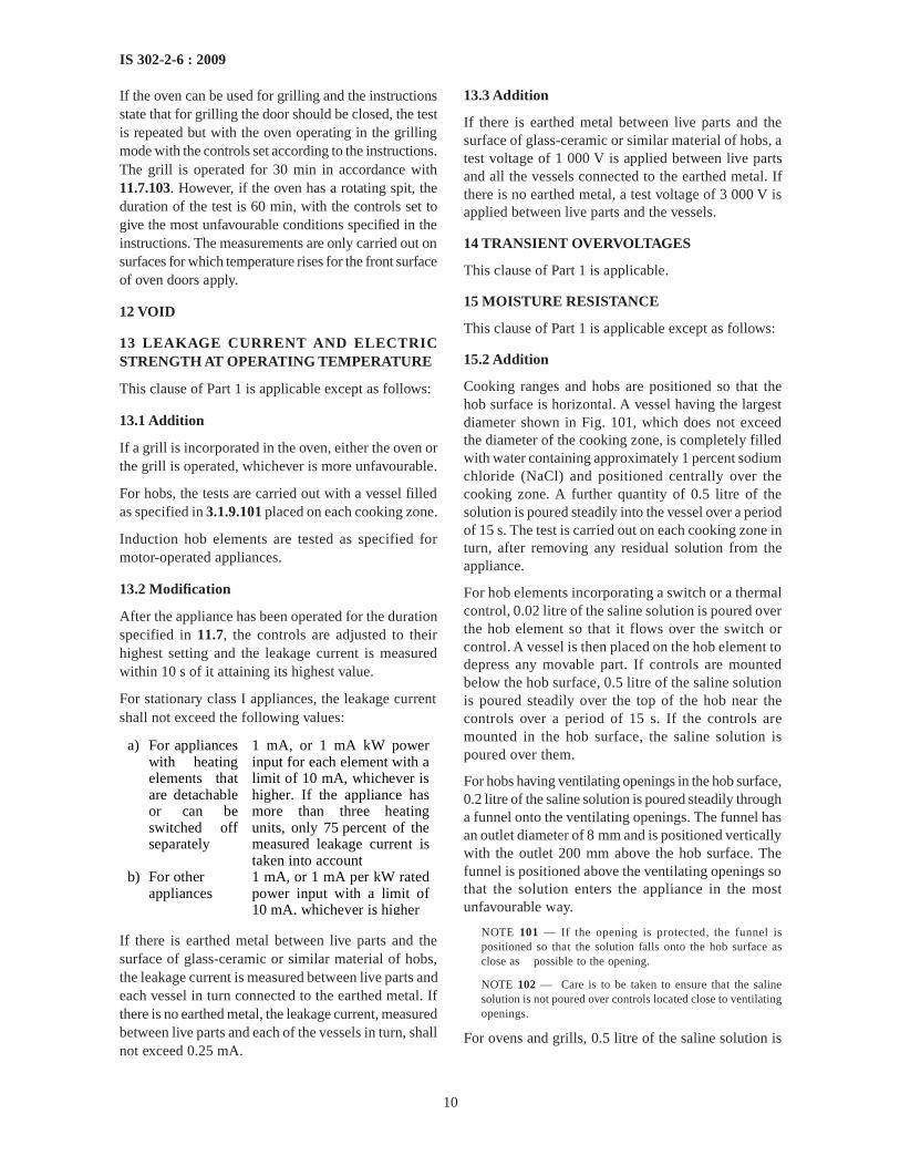
If the oven can be used for grilling and the instructionsstate that for grilling the door should be closed, the testis repeated but with the oven operating in the grillingmode with the controls set according to the instructions.The grill is operated for 30 min in accordance with11.7.103. However, if the oven has a rotating spit, theduration of the test is 60 min, with the controls set togive the most unfavourable conditions specified in theinstructions. The measurements are only carried out onsurfaces for which temperature rises for the front surfaceof oven doors apply.
12 VOID
13 LEAKAGE CURRENT AND ELECTRICSTRENGTH AT OPERATING TEMPERATURE
This clause of Part 1 is applicable except as follows:
13.1 Addition
If a grill is incorporated in the oven, either the oven orthe grill is operated, whichever is more unfavourable.
For hobs, the tests are carried out with a vessel filledas specified in 3.1.9.101 placed on each cooking zone.
Induction hob elements are tested as specified formotor-operated appliances.
13.2 Modification
After the appliance has been operated for the durationspecified in 11.7, the controls are adjusted to theirhighest setting and the leakage current is measuredwithin 10 s of it attaining its highest value.
For stationary class I appliances, the leakage currentshall not exceed the following values:
a) For appliances with heating elements that are detachable or can be switched off separately
1 mA, or 1 mA kW power input for each element with a limit of 10 mA, whichever is higher. If the appliance has more than three heating units, only 75 percent of the measured leakage current is taken into account
b) For other appliances
1 mA, or 1 mA per kW rated power input with a limit of 10 mA, whichever is higher
If there is earthed metal between live parts and thesurface of glass-ceramic or similar material of hobs,the leakage current is measured between live parts andeach vessel in turn connected to the earthed metal. Ifthere is no earthed metal, the leakage current, measuredbetween live parts and each of the vessels in turn, shallnot exceed 0.25 mA.
13.3 Addition
If there is earthed metal between live parts and thesurface of glass-ceramic or similar material of hobs, atest voltage of 1 000 V is applied between live partsand all the vessels connected to the earthed metal. Ifthere is no earthed metal, a test voltage of 3 000 V isapplied between live parts and the vessels.
14 TRANSIENT OVERVOLTAGES
This clause of Part 1 is applicable.
15 MOISTURE RESISTANCE
This clause of Part 1 is applicable except as follows:
15.2 Addition
Cooking ranges and hobs are positioned so that thehob surface is horizontal. A vessel having the largestdiameter shown in Fig. 101, which does not exceedthe diameter of the cooking zone, is completely filledwith water containing approximately 1 percent sodiumchloride (NaCl) and positioned centrally over thecooking zone. A further quantity of 0.5 litre of thesolution is poured steadily into the vessel over a periodof 15 s. The test is carried out on each cooking zone inturn, after removing any residual solution from theappliance.
For hob elements incorporating a switch or a thermalcontrol, 0.02 litre of the saline solution is poured overthe hob element so that it flows over the switch orcontrol. A vessel is then placed on the hob element todepress any movable part. If controls are mountedbelow the hob surface, 0.5 litre of the saline solutionis poured steadily over the top of the hob near thecontrols over a period of 15 s. If the controls aremounted in the hob surface, the saline solution ispoured over them.
For hobs having ventilating openings in the hob surface,0.2 litre of the saline solution is poured steadily througha funnel onto the ventilating openings. The funnel hasan outlet diameter of 8 mm and is positioned verticallywith the outlet 200 mm above the hob surface. Thefunnel is positioned above the ventilating openings sothat the solution enters the appliance in the mostunfavourable way.
NOTE 101 — If the opening is protected, the funnel ispositioned so that the solution falls onto the hob surface asclose as possible to the opening.
NOTE 102 — Care is to be taken to ensure that the salinesolution is not poured over controls located close to ventilatingopenings.
For ovens and grills, 0.5 litre of the saline solution is

11
IS 302-2-6 : 2009
poured over the floor of the oven or grillingcompartment.
For appliances having a drip tray or similar receptacle,the receptacle is filled with the saline solution. A furtherquantity of the solution, equal to 0.01 litre per100 cm2 of the area of the top surface of the receptacle,is poured onto the receptacle through openings in thehob surface. However, the total quantity of solutionshall not exceed 3 litres.
For hobs having a lid, 0.5 litre of the saline solution ispoured uniformly over the closed lid. When the solutionhas run off, the surface is dried and a further 0.125litre of the solution is poured steadily from a height ofapproximately 50 mm onto the centre of the lid over aperiod of 15 s. The lid is then opened as in normal use.
Steam generators intended to be connected to the watermains are supplied at rated water pressure. Controldevices for the supply of water are held open. Water isallowed to flow for 1 min after the first evidence ofoverflow, unless the inflow stops automatically.
NOTE 103 — Only one device is held open at a time.
15.101 Temperature-sensing probes shall beconstructed so that their insulation is not affected bywater.
Compliance is checked by the following test.
The probe is completely immersed in water containingapproximately 1 percent NaCl and having atemperature of 25°C ± 5°C. The water is heated to theboiling point in approximately 15 min. The probe isthen removed from the boiling water and immersed inwater having a temperature of 25°C ± 5°C for 30 min.
This procedure is carried out five times after whichthe probe is removed from the water. All traces of liquidare then removed from the surface.
The probe shall then withstand the leakage current testof 16.2.
NOTE — Detachable temperature-sensing probes are notconnected to the appliance for this test. Non-detachabletemperature-sensing probes are tested in the oven, the probebeing immersed as much as possible.
16 LEAKAGE CURRENT AND ELECTRICSTRENGTH
This clause of Part 1 is applicable except as follows:
16.1 Addition
For hobs, the tests are carried out with a vessel filledas specified in 3.1.9.101 placed on each cooking zone.
Induction hob elements are tested as specified formotor-operated appliances.
16.2 Modification
For stationary class I appliances, the leakage currentshall not exceed the following values:
a) For appliances with heating elements that are detachable or can be switched off separately
1 mA, or 1 mA per kW power input for each element with a limit of 10 mA, whichever is higher. If the appliance has more than three heating units, only 75 percent of the measured leakage current is taken into account
b) For other appliances
1 mA, or 1 mA per kW rated power input with a maximum of 10 mA, whichever is higher
NOTE 101 — If the oven incorporates a grill, or if the applianceincorporates a means to limit the total power input, only theleakage current of those elements that can be switched on atthe same time is taken into consideration.
If there is earthed metal between live parts and thesurface of glass-ceramic or similar material of hobs,the leakage current is measured between live parts andeach vessel in turn connected to the earthed metal. Ifthere is no earthed metal, the leakage current, measuredbetween live parts and each of the vessels in turn, shallnot exceed 0.25 mA.
16.3 Addition
If there is earthed metal between live parts and thesurface of glass-ceramic or similar material of hobs, atest voltage of 1 250 V is applied between live partsand all the vessels connected to the earthed metal. Ifthere is no earthed metal, a test voltage of 3 000 V isapplied between live parts and the vessels.
17 OVERLOAD PROTECTION OF TRANS-FORMERS AND ASSOCIATED CIRCUITS
This clause of Part 1 is applicable.
18 ENDURANCE
This clause of Part 1 is not applicable.
19 ABNORMAL OPERATION
This clause of Part 1 is applicable except as follows.
19.1 Addition
For induction hobs, compliance is also checked by thetests of 19.101 and 19.102, but 19.4 is not applicable.
Temperature-sensing probes are placed in the oven inany position likely to occur during normal use except

12
IS 302-2-6 : 2009
that they are not connected to control the oventemperature.
19.2 Addition
Hob elements are operated without a vessel, pandetectors being rendered inoperative. Oven doors areopen or closed, whichever is more unfavourable. Hoblids are closed unless the hob elements are interlockedwith the lid or an indicator lamp shows that a hobelement is switched on.
NOTE 101 — A lamp that is switched on and off by a thermostator energy regulator does not show that the hob element isswitched on.
For appliances incorporating more than one heatingunit, the test is only carried out with the heating unitresulting in the most unfavourable conditions, itscontrol being adjusted to the highest setting. If theappliance incorporates an oven without an indicatorlamp to show that the oven is switched on, the oven isalso operated, its control being adjusted to the highestsetting.
NOTE 102 — A lamp used for illuminating the oven, visiblethrough the door and which is automatically switched on andoff together with the oven, is considered to be an indicatorlamp.
If an induction hob element has a metallic lid, a forceof 30 N is applied to the closed lid in the mostunfavourable place by means of test probe B of IS 1401.
Pyrolytic self-cleaning ovens are also operated undercleaning conditions, motors that operate duringcleaning being switched off or disconnected in turn.
NOTE 103— Examples are motors of fans and timers.
Induction hob elements are operated under theconditions of 11 but with empty vessels, the controlsbeing adjusted to the highest setting.
Steam ovens are operated without water.
Doors of separate grill compartments incorporated ina cooking range are open or closed, whichever is moreunfavourable.
19.9 Not applicable
19.11.2 Addition
During simulation of the fault conditions, it shall bepossible to switch off any energized hob element.
The fault conditions are also simulated with all hobelements switched off, the appliance being supplied atrated voltage. If a pan detector is incorporated, asuitable vessel is placed on the cooking zone.
The hob elements shall not become energized.
19.13 Addition
The temperature rise limit of 150 K also applies towooden cabinets and rectangular boxes.
The temperature in the centre of pyrolytic self-cleaningovens during the test of 19.4 shall not exceed 425°Cwhenever the oven door can be opened.
The temperature rise of the windings of induction hobelements shall not exceed the values specified in 19.7.
The electric strength test of induction hob elements iscarried out immediately after switching off theappliance.
Glass in oven doors shall not be damaged.
19.101 Induction hob elements are supplied at ratedvoltage and operated with a steel disc placed on thecentre of the cooking zone. The disc has a thickness of6 mm and the smallest diameter, rounded up to thenearest centimetre that allows the hob element tooperate.
19.102 Induction hob elements are supplied at ratedvoltage and operated under normal operation but withthermal controls short-circuited.
The temperature rise of the oil shall not exceed 270 K.
20 STABILITY AND MECHANICAL HAZARDS
This clause of Part 1 is applicable except as follows:
20.101 Cooking ranges and ovens shall have adequatestability when the open door is subjected to a load.
Compliance is checked by the following test.
Appliances with horizontally hinged doors are placedon a horizontal surface and a mass is placed on thecentre of the open door. For non-rectangular doors,the mass is placed on the part farthest from the hingewhere it could be placed in normal use.
For appliances normally placed on the floor the massis:
a) 22.5 kg, for oven doors; and
b) 7 kg, for other doors.
For appliances normally placed on a table, the mass is7 kg.
For appliances normally placed on the floor and havingvertically hinged doors, a mass of 15 kg is placed inthe most unfavourable position on the open door.
NOTE 1 — The oven shelves are placed in the mostunfavourable position.
NOTE 2 — A sandbag may be used for the load.
NOTE 3 — For an appliance having more than one door, thetest is carried out on each door separately.
13
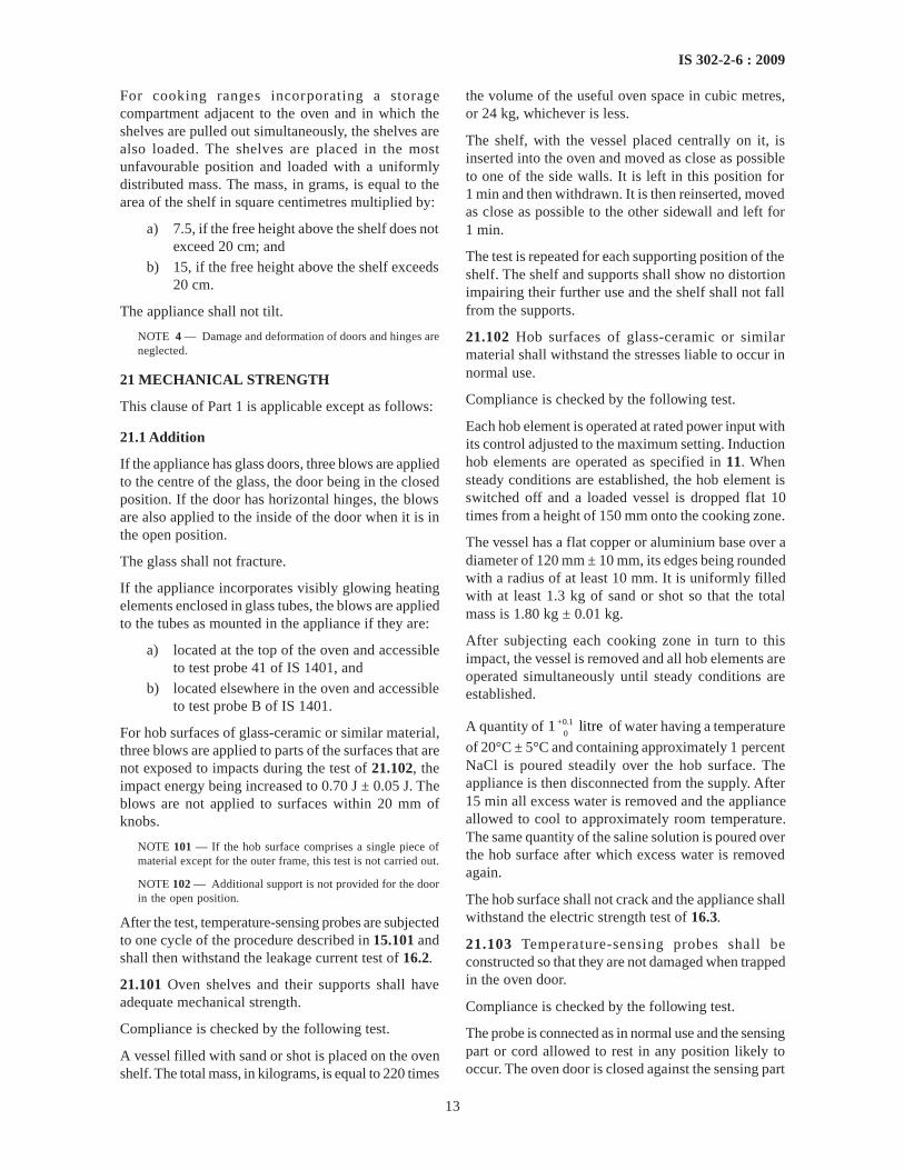
IS 302-2-6 : 2009
For cooking ranges incorporating a storagecompartment adjacent to the oven and in which theshelves are pulled out simultaneously, the shelves arealso loaded. The shelves are placed in the mostunfavourable position and loaded with a uniformlydistributed mass. The mass, in grams, is equal to thearea of the shelf in square centimetres multiplied by:
a) 7.5, if the free height above the shelf does notexceed 20 cm; and
b) 15, if the free height above the shelf exceeds20 cm.
The appliance shall not tilt.
NOTE 4 — Damage and deformation of doors and hinges areneglected.
21 MECHANICAL STRENGTH
This clause of Part 1 is applicable except as follows:
21.1 Addition
If the appliance has glass doors, three blows are appliedto the centre of the glass, the door being in the closedposition. If the door has horizontal hinges, the blowsare also applied to the inside of the door when it is inthe open position.
The glass shall not fracture.
If the appliance incorporates visibly glowing heatingelements enclosed in glass tubes, the blows are appliedto the tubes as mounted in the appliance if they are:
a) located at the top of the oven and accessibleto test probe 41 of IS 1401, and
b) located elsewhere in the oven and accessibleto test probe B of IS 1401.
For hob surfaces of glass-ceramic or similar material,three blows are applied to parts of the surfaces that arenot exposed to impacts during the test of 21.102, theimpact energy being increased to 0.70 J ± 0.05 J. Theblows are not applied to surfaces within 20 mm ofknobs.
NOTE 101 — If the hob surface comprises a single piece ofmaterial except for the outer frame, this test is not carried out.
NOTE 102 — Additional support is not provided for the doorin the open position.
After the test, temperature-sensing probes are subjectedto one cycle of the procedure described in 15.101 andshall then withstand the leakage current test of 16.2.
21.101 Oven shelves and their supports shall haveadequate mechanical strength.
Compliance is checked by the following test.
A vessel filled with sand or shot is placed on the ovenshelf. The total mass, in kilograms, is equal to 220 times
the volume of the useful oven space in cubic metres,or 24 kg, whichever is less.
The shelf, with the vessel placed centrally on it, isinserted into the oven and moved as close as possibleto one of the side walls. It is left in this position for1 min and then withdrawn. It is then reinserted, movedas close as possible to the other sidewall and left for1 min.
The test is repeated for each supporting position of theshelf. The shelf and supports shall show no distortionimpairing their further use and the shelf shall not fallfrom the supports.
21.102 Hob surfaces of glass-ceramic or similarmaterial shall withstand the stresses liable to occur innormal use.
Compliance is checked by the following test.
Each hob element is operated at rated power input withits control adjusted to the maximum setting. Inductionhob elements are operated as specified in 11. Whensteady conditions are established, the hob element isswitched off and a loaded vessel is dropped flat 10times from a height of 150 mm onto the cooking zone.
The vessel has a flat copper or aluminium base over adiameter of 120 mm ± 10 mm, its edges being roundedwith a radius of at least 10 mm. It is uniformly filledwith at least 1.3 kg of sand or shot so that the totalmass is 1.80 kg ± 0.01 kg.
After subjecting each cooking zone in turn to thisimpact, the vessel is removed and all hob elements areoperated simultaneously until steady conditions areestablished.
A quantity of +0.10
1 litre of water having a temperature
of 20°C ± 5°C and containing approximately 1 percentNaCl is poured steadily over the hob surface. Theappliance is then disconnected from the supply. After15 min all excess water is removed and the applianceallowed to cool to approximately room temperature.The same quantity of the saline solution is poured overthe hob surface after which excess water is removedagain.
The hob surface shall not crack and the appliance shallwithstand the electric strength test of 16.3.
21.103 Temperature-sensing probes shall beconstructed so that they are not damaged when trappedin the oven door.
Compliance is checked by the following test.
The probe is connected as in normal use and the sensingpart or cord allowed to rest in any position likely tooccur. The oven door is closed against the sensing part

14
IS 302-2-6 : 2009
or cord and a force of 90 N is applied to the door in themost unfavourable place for 5 s.
The probe shall then comply with 8.1, 15.101 and 29.
NOTE — The oven is not operated during this test.
21.104 Glass panels of horizontally hinged oven doorsshall withstand the thermal shock liable to occur innormal use.
Compliance is checked by the following test.
The appliance is operated as specified in 11. The dooris then opened and 0.2 l of water having a temperatureof 20°C ± 5°C is poured within 5 s onto the centre ofthe glass panel.
The glass shall not fracture.
NOTE — The test is not carried out after the cleaning cycle ofpyrolytic self-cleaning ovens.
22 CONSTRUCTION
This clause of Part 1 is applicable except as follows:
22.21 Addition
NOTE 101— Magnesium oxide and mineral ceramic fibresused for the electrical insulation of heating elements are notconsidered to be hygroscopic materials.
22.101 Hobs shall be constructed so that hob elementsare prevented from rotating about a vertical axis andare adequately supported in all positions of adjustmentof their supports.
NOTE — If a hob element is clamped by a nut on a centralstud, an additional means is required to prevent its rotation.
Hobs with detachable hob elements shall beconstructed so that damage is unlikely to occur whilethe hob elements are being removed or replaced.
Compliance is checked by inspection.
22.102 Timers intended to delay the operation of aheating element shall not control a radiant grill, unlessthe grill is thermally controlled and incorporated in anoven or other compartment.
Compliance is checked by inspection.
22.103 Oven vents shall be constructed so that anymoisture or grease discharged through them cannotaffect clearances and creepage distances between liveparts and other parts of the appliance.
Compliance is checked by inspection.
22.104 Steam ovens shall be constructed so that steamvents and ducts are unlikely to become blocked duringnormal use.
Compliance is checked by inspection.
22.105 Built-in ovens shall only be vented through the
front, unless provision is made for venting through aduct.
Compliance is checked by inspection.
22.106 Grills shall be constructed so that grill panscan be easily positioned without jamming.
The grill pans shall not fall from the support whenmoved sideways.
Compliance is checked by inspection and by manualtest.
22.107 Pyrolytic self-cleaning ovens shall switch offautomatically at the end of the cleaning process andrequire a manual operation to start another cleaningcycle.
Compliance is checked by inspection.
22.108 Pyrolytic self-cleaning ovens shall beconstructed so that opening and closing of the doordoes not impair the interlock system or damage thedoor seal.
Compliance is checked by the following test.
The door is opened at least 10 cm and is then closedby applying a force of 90 N to the handle. Thisoperation is carried out 5 000 times. Every 1 000 cycles,the interlock system for the self-cleaning function isoperated.
After the test, the interlock system shall be fit for furtheruse and the door seal shall not be damaged.
22.109 Pyrolytic self-cleaning ovens shall incorporatean interlock so that access to the oven cannot be gainedwhen the temperature in the centre of the oven exceeds350°C, even if the interlock is defective.
Compliance is checked by inspection and by thefollowing test.
The oven is supplied at rated voltage and operatedunder cleaning conditions, after which it is allowedto cool. While the temperature in the centre of theoven exceeds 350°C, a force of 90 N is applied tolevers and handles, and a torque of 2 Nm is appliedto rotary knobs. It shall not be possible to open thedoor.
The test is repeated with any defect that may beexpected in normal use applied to the interlock system,including interruption of the supply, only one defectbeing simulated at a time.
NOTE 1 — Examples of defects are the breakage of a spring,or a gravity-operated part failing to drop into position.
NOTE 2 — Fault conditions applied during the tests of 19 arenot repeated.
22.110 Pyrolytic self-cleaning ovens shall be

15
IS 302-2-6 : 2009
constructed so that ignitable gases cannot be dischargedthrough vents during the cleaning process.
Compliance is checked by the following test.
A mixture of 30 g of gravy and 15 g of hydrogenatedoil shortening is spread evenly over the interior of theoven, including the door. The oven is operated for 3 hat the maximum setting of the thermostat.
NOTE 1 — The gravy consists of two-thirds by mass of beefextract and one-third water.
The oven is then operated under cleaning conditionsand attempts are made to ignite gases that may bedischarged through vents by bursts of sparks. Thesparks are approximately 3 mm long, each spark havingan energy of at least 0.5 J.
The sparks are applied when the temperature in thecentre of the oven reaches 300°C and at eachsubsequent temperature rise of 50 K.
NOTE 2 — The electrodes used to produce the sparks aremoved in and around the vents through which gases may bedischarged.
There shall be no continuous burning of gases.
If the oven incorporates a heating element intended toeliminate smoke, the test is repeated with this heatingelement disconnected if the temperature in the centreof the oven exceeds 450°C under cleaning conditions.
22.111 Pyrolytic self-cleaning ovens shall beconstructed so that there is no risk of emission of flamesduring the cleaning process.
Compliance is checked by the following test.
A suitable vessel containing 100 g of salt-free butter isplaced on the centre of the oven floor.
The electrodes of a spark generator are positionedapproximately 7.5 cm above the surface of the butter.
The oven is then operated under cleaning conditionsand bursts of sparks are produced. The sparks areapproximately 3 mm long, each spark having an energyof at least 0.5 J. The sparks are generated when thetemperature in the centre of the oven reaches 300°Cand at each subsequent temperature rise of 50 K.
There shall be no emission of flames through doorseals, vents or other openings.
22.112 Hobs shall be constructed so that hinged lidscannot close accidentally.
Compliance is checked by inspection and by manualtest.
NOTE — This requirement may be met if the hingeincorporates a click stop or similar means, or if the lid can beopened through an angle of at least 100°C, when the applianceis placed against a wall.
22.113 Hobs shall be constructed so that inadvertentoperation of touch controls is unlikely if this could giverise to a hazardous situation due to:
a) spillage of liquids, including that caused by avessel boiling over; and
b) a damp cloth placed on the control panel.
Compliance is checked by the following test, theappliance being supplied at rated voltage. The test iscarried out with each hob element energized in turnand then without energizing any hob elements.
Sufficient water to completely cover the control panelto a depth not exceeding 2 mm, with a minimum of140 ml, is poured steadily over the control panel so thatbridging occurs between combinations of touch pads.
A cloth having a mass between 140 g/m2 and 170 g/m2,and dimensions approximately 400 mm × 400 mm, isfolded four times into a square pad, saturated with waterand placed over the control panel in any position.
There shall be no operation of any hob element forlonger than 10 s.
During the test, it shall be possible to switch off theenergized hob element by operating the touch controls,unless it switches off automatically.
22.114 Hobs having touch controls shall require at leasttwo manual operations to switch on a hob element butonly one operation to switch it off. However, additionalhob elements may be switched on by a single manualoperation. In this case, 1 min after all the hob elementshave been switched off, two manual operations arerequired to re-energize one hob element.
NOTE — Touching the contact surface at the same point twiceis not considered to be two operations.
Hobs having touch controls shall incorporate visualmeans to indicate when each hob element is energized.
Compliance is checked by inspection and by manualtest.
22.115 Induction hob elements, and other hob elementsincorporating a pan detector, shall be constructed sothat the hob element can only be operated when a vesselis placed on the cooking zone.
Compliance is checked by the following test, theappliance being supplied at rated voltage.
An iron bar 2 mm thick, having dimensionsapproximately 100 mm × 20 mm is placed in the mostunfavourable position on each cooking zone in turn.The controls are adjusted to their highest setting.
For induction hob elements, the temperature rise ofthe bar shall not exceed 35 K. Other hob elements shallnot operate.

16
IS 302-2-6 : 2009
22.116 Hob elements incorporating a pan detector shallbe constructed so that the hob element is not switchedon by the vesselz if it has been removed for more than10 min.
Compliance is checked by manual test.
22.117 In appliances incorporating a pan detector, asignal lamp shall indicate when the control for the hobelement is not switched to the off position.
Compliance is checked by inspection.
22.118 It shall not be possible to operate a grill whilethe plug of a supply cord is engaged in a socket-outletlocated directly above the door.
Compliance is checked by inspection and by manualtest.
22.119 Cooking ranges incorporating a retractabledeflector to prevent excessive temperatures on controlknobs shall be constructed so that the user is unlikelyto touch hot surfaces of the deflector when operatingthe controls.
Compliance is checked by measuring the distancebetween the deflector in its extended position and thatpart of the control knob touched in normal use. It shallbe at least 25 mm, or the temperature rise of those partswithin 25 mm of the knob shall not exceed the limitsfor handles, knobs, grips and similar parts held for shortperiods only, as specified in Table 3.
22.120 Outer glass panels of oven doors shall be madefrom glass that breaks into small pieces when itfractures.
Compliance is checked by carrying out the testspecified in 8.10 of ISO 15717. There shall be at least60 pieces in any 50 mm × 50 mm area.
22.121 Outer glass panels of oven doors that areintended to be removed by the user for cleaning shallbe constructed so that they cannot be fixed in anincorrect orientation.
Compliance is checked by inspection and by manualtest.
23 INTERNAL WIRING
This clause of Part 1 is applicable except as follows:
23.3 Addition
The requirement also applies if parts of a cooking rangeare folded onto the hob surface, or separated from theirnormal position, for transportation purposes.
24 COMPONENTS
This clause of Part 1 is applicable except as follows:
24.1.3 Addition
Switches controlling hob elements are subjected to30 000 cycles of operation.
NOTE — This does not apply to switches having only oneclosed position.
24.1.4 Addition
a) Energy regulators:
1) for automatic action 100 000
2) for manual action10 000
b) Self-resetting thermal cut-outs:
1) for heating elements of 100 000glass-ceramic hobs
2) for heating elements of other 10 000hobs
c) Thermostats controlling the clea- 3 000
ning process in pyrolytic self-cleaning ovens
24.101 Thermostats and energy regulatorsincorporating an off position shall not switch on as aresult of variations in ambient temperatures.
Compliance is checked by the following test that iscarried out on three samples of the control.
The control, adjusted to the off position, is placed for
2 h in an ambient temperature of 0
–5–20 °C, and thenat:
a) t°C, where t is the temperature according tothe T-marking; and
b) 55°C, for controls without a T-marking.
During the test, the off position shall be maintained.
A test voltage of 500 V is applied across the contactsfor 1 min. No breakdown shall occur.
24.102 Socket-outlets incorporated in cooking rangesshall be single-phase, incorporate an earthing contactand have a rated current not exceeding 16 A. Both polesshall be protected by fuses or miniature circuit-breakershaving a rated current not exceeding the rated currentof the socket-outlet. They shall be placed behind a non-detachable cover. However, if the cooking range isintended to be permanently connected to fixed wiringor is fitted with a polarized plug, the neutral pole neednot be protected.
Compliance is checked by inspection.
NOTE 1 — The actuating member of miniature circuit-breakersmay be accessible.
NOTE 2 — A non-detachable cover is not required if fusesbecome accessible after opening a drawer or othercompartment.

17
IS 302-2-6 : 2009
25 SUPPLY CONNECTION AND EXTERNALFLEXIBLE CORDS
This clause of Part 1 is applicable except as follows:
25.3 Addition
Hobs, built-in ranges and built-in ovens may beconnected to the supply mains before the appliance isinstalled.
25.14 Addition
For temperature-sensing probes, the total number offlexing is 5 000. Probes with circular-section cords areturned through 90° after 2 500 flexings.
26 TERMINALS FOR EXTERNAL CONDUCTORS
This clause of Part 1 is applicable.
27 PROVISION FOR EARTHING
This clause of Part 1 is applicable.
28 SCREWS AND CONNECTIONS
This clause of Part 1 is applicable.
29 CLEARANCES, CREEPAGE DISTANCESAND SOLID INSULATION
This clause of Part 1 is applicable except as follows:
29.2 Addition
The microenvironment is pollution degree 3 unless theinsulation is enclosed or located so that it is unlikelyto be exposed to pollution during normal use of theappliance.
29.3 Addition
This requirement does not apply to the sheath of avisibly glowing heating element inaccessible to testprobe 41 of IS 1401.
30 RESISTANCE TO HEAT AND FIRE
This clause of Part 1 is applicable except as follows:
30.2 Addition
For grills and griddles that do not incorporate atimer,30.2.2 is applicable. For other appliances, 30.2.3is applicable.
31 RESISTANCE TO RUSTING
This clause of Part 1 is applicable.
32 RADIATION, TOXICITY AND SIMILARHAZARDS
This clause of Part 1 is applicable except as follows:
32.101 Pyrolytic self-cleaning ovens shall beconstructed so that carbon monoxide is not dischargedin hazardous quantities during cleaning.
Compliance is checked by the following test.
Twice the quantity of the mixture specified in 22.110is spread evenly over the interior of the oven,including the door. The oven is supplied at ratedvoltage and operated for 3 h at the maximum settingof the thermostat.
The oven is then allowed to cool to room temperatureand placed in a closed test room having a volume of20 m3 to 25 m3, in which the air is circulated by alow-speed fan. The oven is operated under cleaningconditions and the concentration of carbon monoxideis measured 1 m above the centre of the floor.
The concentration of carbon monoxide shall notexceed 0.015 percent.
If the oven incorporates a heating element intendedto eliminate smoke, the test is repeated with thisheating element disconnected, unless the cleaningprocess can only be performed when the heatingelement is in circuit.
101 TESTS
101.1 Type Tests
The tests specified in Table 103 shall constitute thetype tests and shall be carried out on a sample selectedpreferably at random from regular production lot(see5.3). Before commencement of the tests, the ironsshall be visually examined and inspected ofcomponents, parts and their assembly, constructions,mechanical hazards, marking provision of suitableterminals for supply connections, earthing and theeffectiveness screws and connection. The externalsurface finish shall be even and free from finishingdefects.
101.1.1 Criteria of Acceptance
Sample shall successfully pass all the type tests forproving conformity with the requirements of thestandard. If the sample fails in any of the type tests,the testing authority, at its discretion, may call forfresh samples not exceeding twice the original numberand subject them again to all tests or to the test(s) in

18
IS 302-2-6 : 2009
Table 103 Schedule of Type Tests(Clause 101.1)
Sl No. Tests Clause Reference
(1) (2) (3)
i) Protection against access to live parts 8ii) Power input and current 10
iii) Heating 11iv) Leakage current and electric strength at 13
operating temperaturev) Transient overvoltages 14
vi) Moisture resistance 15vii) Leakage current and electric strength 16
viii) Overload protection of transformers and 17associated circuits
ix) Abnormal operation 19x) Stability and mechanical hazards 20
xi) Mechanical strength 21xii) Construction 22
xiii) Internal wiring 23xiv) Components 24xv) Supply connection and external flexible cords25
xvi) Terminals for external conductors 26xvii) Provision for earthing 27xviii) Screws and connections 28xix) Clearances, creepage distances and solid 29
insulationxx) Resistance to heat and fire 30
xxi) Resistance to rusting 31xxii) Radiation, toxicity and similar hazards 32
101.2 Acceptance Tests
The following shall constitute the acceptance tests:
Test Clause Reference
(1) (2)
a) Protection against access to 8live parts
b) Power input and current 10c) Heating 11d) Leakage current and electric 13
strength at operating temperature
e) Moisture resistance 15f) Leakage current and electric 16
strengthg) Provision for earthing 27
NOTE — For the purpose of acceptance tests, the humiditytreatment shall be done for 24 h while conducting the test formoisture resistance (15).
101.2.1 A recommended sampling procedure foracceptance tests is given in Annex J of IS 302-1.
101.3 Routine Tests
The following shall constitute the routine tests:
Test Clause Reference
(1) (2)a) Protection against access to 8
live parts
b) High voltage 13.3.2 of IS 302-1c) Provision for earthing 27
which failure(s) had occurred. No failure should bepermitted in the repeat test(s).
ANNEXESThe Annexes of Part 1 are applicable.

Bureau of Indian Standards
BIS is a statutory institution established under the Bureau of Indian Standards Act, 1986 to promoteharmonious development of the activities of standardization, marking and quality certification of goodsand attending to connected matters in the country.
Copyright
BIS has the copyright of all its publications. No part of these publications may be reproduced in any formwithout the prior permission in writing of BIS. This does not preclude the free use, in the course ofimplementing the standard, of necessary details, such as symbols and sizes, type or grade designations.Enquiries relating to copyright be addressed to the Director (Publications), BIS.
Review of Indian Standards
Amendments are issued to standards as the need arises on the basis of comments. Standards are also reviewedperiodically; a standard along with amendments is reaffirmed when such review indicates that no changes areneeded; if the review indicates that changes are needed, it is taken up for revision. Users of Indian Standardsshould ascertain that they are in possession of the latest amendments or edition by referring to the latest issue of‘BIS Catalogue’ and ‘Standards : Monthly Additions’.
This Indian Standard has been developed from Doc No.: ETD 32 (5972).
Amendments Issued Since Publication
Amend No. Date of Issue Text Affected
BUREAU OF INDIAN STANDARDS
Headquarters:
Manak Bhavan, 9 Bahadur Shah Zafar Marg, New Delhi 110002Telephones : 2323 0131, 2323 3375, 2323 9402 Website: www.bis.org.in
Regional Offices: Telephones
Central : Manak Bhavan, 9 Bahadur Shah Zafar Marg 2323 7617NEW DELHI 110002 2323 3841
Eastern : 1/14 C.I.T. Scheme VII M, V. I. P. Road, Kankurgachi 2337 8499, 2337 8561KOLKATA 700054 2337 8626, 2337 9120
Northern : SCO 335-336, Sector 34-A, CHANDIGARH 160022 60 384360 9285
Southern : C.I.T. Campus, IV Cross Road, CHENNAI 600113 2254 1216, 2254 14422254 2519, 2254 2315
Western : Manakalaya, E9 MIDC, Marol, Andheri (East) 2832 9295, 2832 7858MUMBAI 400093 2832 7891, 2832 7892
Branches: AHMEDABAD. BANGALORE. BHOPAL. BHUBANESHWAR. COIMBATORE. DEHRADUN.FARIDABAD. GHAZIABAD. GUWAHATI. HYDERABAD. JAIPUR. KANPUR. LUCKNOW.NAGPUR. PARWANOO. PATNA. PUNE. RAJKOT. THIRUVANANTHAPURAM.VISAKHAPATNAM.
{
{{
{
{
Laser Typeset by Sunshine Graphics


![[XLS] · Web view1 302 2 302 3 302 4 302 5 302 6 363 7 363 8 302 9 302 10 307 11 302 12 302 13 223244 14 302 15 302 16 224 17 302 18 302 19 302 20 302 21 302 22 23 24 25 26 302 27](https://img.pdfslide.net/doc/110x75/5b00c3a37f8b9a952f8d6104/xls-view1-302-2-302-3-302-4-302-5-302-6-363-7-363-8-302-9-302-10-307-11-302-12.jpg)