Embed Size (px)
Citation preview

Disclosure to Promote the Right To Information
Whereas the Parliament of India has set out to provide a practical regime of right to information for citizens to secure access to information under the control of public authorities, in order to promote transparency and accountability in the working of every public authority, and whereas the attached publication of the Bureau of Indian Standards is of particular interest to the public, particularly disadvantaged communities and those engaged in the pursuit of education and knowledge, the attached public safety standard is made available to promote the timely dissemination of this information in an accurate manner to the public.
इंटरनेट मानक
“!ान $ एक न' भारत का +नम-ण”Satyanarayan Gangaram Pitroda
“Invent a New India Using Knowledge”
“प0रा1 को छोड न' 5 तरफ”Jawaharlal Nehru
“Step Out From the Old to the New”
“जान1 का अ+धकार, जी1 का अ+धकार”Mazdoor Kisan Shakti Sangathan
“The Right to Information, The Right to Live”
“!ान एक ऐसा खजाना > जो कभी च0राया नहB जा सकता है”Bhartṛhari—Nītiśatakam
“Knowledge is such a treasure which cannot be stolen”
“Invent a New India Using Knowledge”
है”ह”ह
IS 3266 (1982): Electroplated coatings of gold for generalengineering purposes [MTD 7: Light Metals and their Alloys]


IS : 3266 -‘198i!
Indian Standard
SPE&FICATION FOR E&ECTROPLgTED COATINGS OF GOLD FOR
‘GI?iNERAL ENGINEERING PURPOSES :
?$et#ic Finishes Sectional- Committee,“SMDC. 23
cha@zn DB R. C. SHA~MA
Mmbars
Soar K. BALAKRIBHNAN
Repesenting ’ Eveready Flashlight Company, Lucknow
Central Electrochemical Research Institute ( C$IR );Karaikudi
S~sr S. R. NATARAJAN ( Altemate ) SHEI G. S. BHATTACHARJEE Ministry of &fence (R & D )
SHEI I. N. BHATIA ( Alternate ) SHEI S. C. BEAWAL National Test House, Calcutta
SHRI A. K. KAL~A ( Alternate) SHRI A. T. BORATE Premier Automobiles Ltd, Bombay
SHRI A. G. PBABHU ( Alternate ) SHRI M. Y. BORKER Ministry of Defence ( DGI )
SERI P. K. SIN ( Altnnatu ) SHBI M. S. CHAKRAVORTY Premier Metal Finishers ( P ) Ltd, Calcutta
SHRI R. K. CHATTERJEE ( Alternate ) SARI AHINDRA CHATTERJEE Canning Mitra Phoenix Ltd, Bombay SHBI KANTILAL T. DALAL Kohinoor Electra-Gilders, Bombay
SHRI JAYENDRA K. DALAL (Alternate ) DE R. P. DAMBAL Indian Telephone Industries Ltd, Bangalore DEPUTY DIREOTOR ( CHEM ), Ministry of Railways
RDSO, LVCKNOW CHEWST & METALLURQIIT,
ICF, MADRAS ( Alternate ) SHRI G. T. DESHMUKH Perfect Industries, Pune
SERI G. S. EKBOTE ( Alternatr ) SHRI S. E. EMANUAL Hindustan Aeronautics Ltd, Bangalore SHRI S. N. GANA Indian Posts and Telegraphs Department,
Calcutta SHRI P. B. SYAY ( Ahmate)
( Continued on page 2 )
@ Copyight 1983
INDIAN STANDARDS INSTITUTION
This publication is protected under the Indian Co&right Act (XIV of 1957 ) and reproduction in whole or in part by any means except with written permission of the publisher shall be deemed to be an infringement of copyright under the said Act.

( Continued from page 1)
Membns &presmling
SHBI K. HII~ALAL NGEF Ltd, Bangalore SERI ABWATHANARAYANA ( Alhnati )
SHXI V. S. KULKABNI Grauer arxI Weil ( India ) Ltd, Bombay SERI SIJEZIIL. G~INKA ( Altemah )
DR S. K. NA~AN~ National Metallurgical Laboratory ( CSIR ), Jamskdpur
SHRI R. SEN Hindustan Cables Ltd, Rupnarainpur ( Dist Burdwan )
SHRI KALYAN GHOSH ( A1:emuf-a~) SBRI R. A. SHAH RbnulP Industries Ltd, Bombay
KUMARI MBIDULAA.SEAH(A~~~~U~C) S~arR.So~ae~~ars~ Bbarat Electronics Ltd, Bangalore
SFIRI K. NA~EER ( Ahmats ) SEEI V. THIYAQARAJAN Development Commihibner ( Small Industries
Services Institute ), New Delhi Saar R. VENKATARAMAN T. I. Cycles of India, Madras SHRI C. R. RAMA RAO, Director General, IS1 ( Ex-ow Men&r )
Director ( Strut & M&t )
Sirsz S. K, GIJPTA Assistant Director ( Met ); IS1
T

Indian Standard
SPECIFICATION ‘FOR -ELECTROPLATED COAXWKIZS \OF GOLD .FQR
GENERAL ENGINEERING PWRPClSE?S
( First Revision ‘)
0. FOR.ExW O&D
-0.1 This Indian standard ( First Revision)) was zadopted by the ‘Indian Standards :Institution on 17 May 1982, after the &eift +inalized i by 1 the Metallic Finishes Sectional Committee ahad >.been &Bproved ‘by the Structural and Metals Division Council.
.0.!2 Some of the important characteristics of ,gdd coatings, such as, resistance to tarnish and corrosion, bondability, ‘low and stable electrical contact resistance, solderability and infrared ,rcflectivity are (made use of in general engineering applications, such as, electrical contacts, soldered connections, printed circuit boards, separable connectors, .terminals, springs, analytical weights, reflectors, wave guides, etc.
0.3 This standard was first published in 1965. In this revision, the purity of the coatings. has been modified and the coatings have been related to knoop hardness ranges. Also minimum thicknesses of undercoats of various basis metals have been given for the guidance. -Thicknesses of gold coatings have also been rationalized.
OH In the preparation of this standard necessary assistance has been derived from ISO/DP 4523-2. Electrodeposited coating of gold ( and gold alloy ) for general engineering purposes ( second draft,proposal ).
0.5 For the purpose of deciding whether a particular requirement of this standard is complied with, the final value, observed or calculated, expressing the result of a test or analysis, shall be rounded off in accordance with IS : 2-1960’. The number of significant places retained in the rounded off value should be the same as that of the specified value in this standard.
“Ruler’for rounding off numerical values ( ravisid 1.
3

‘IS ,: 3266 - 1982
1. SCOPE
1.1 This standard covers requirements for electrodeposited gold coatings on copper, brass, zinc and zinc alloys, steel, nickel, silver, aluminium and its alloys.
1.1.1 This standard does not cover coatings applied on sheet, stripand wire in the unfabricated form.
2. TERiMINOLaGY / ,
2.0 For the purpose of this standard, the following definitions shall
apply. 2.1 Surface - The surface on which an electroplater has to work.
2.2 Significant Surface - The part of the surface which is to be covered by the coating and which is essential to the appearance or serviceability of the article. When necessary, the significant surface shall be a subject of agreement ,between the purchaser and the plater ahd ‘has :to be indicated on drawings or by the provision of suitably marked samples.
3. CLASSIFICATION ‘NUMBER
3.1 The classification number comprises:
a>
W
cl
‘4 3.1.1
Example
%xaniple
the chemical symbol for the basis metal or for the principal metal if an alloy or in the .case of non-metallic materials, the letters NM followed-by an oblique stroke;
where appropriate, the chemical symbol(s) for the undercoat metal(s), as follows:
‘Ni for nickel
cu for copper
‘, Cu/Ni for nickel on copper Sn-Ni for tin-nickel, alloy
followed by an oblique stroke; the chemical symbol, Au, for gold followed if required by a number in ,parentheses representing ,the minimum percentage gold content by mass; a number indicating the, minimum thickness ( in micrometres ) of the gold coating on the significant surface.
Examples of complete classification numbers are as follows:
1 - A 99 percent gold coating having a thickness of 5 pm ( minimum ) on steel, using a nickel undercoat, has the classification number : Fe/Ni/Au(99)5.
2 -.A 99 .percent gold coating, having a thickness of 2 ym ( minimum ), on zinc alloy, using an undercoat of nickel on copper, has the classification number : Zn/Cu/Ni[Au(99)2.

iS : 5266 - i982
Example 3 - A 99-7 percent gold coating, having a thickness of 0’5 pm ( minimum ), on copper alloy, has the classification number: Cu/Au(99*7)0-5.
4. PURITY OF COATING
4.1 When tested in accordance with 4.2, the purity of coating shall be as follows:
OPe Purity, percent Min
1 99.99 2 99-90
3 99.70 4 99.0 5 95-o
4.2 The purity shall be determined by any one of the method specified in Appendix A.
5. MATERIAL AND WORKMANSHIP
5.1 Electroplated article shall be clean and free from damage. Over the significant surface, the electroplated article shall be free from defects such as pits, roughness, cracks or uncoated areas visible when viewed at a magnification of 8X. In addition, blistering or other signs of poor adhesion may not be tolerated on any surface of the article. On articles where a contact mark on the significant surface is unavoidable, its position shall be the subject of agreement between the supplier and the purchaser.
6. CONDITIO’NS AND PRE-TREATMENT
6.1 Pre-plating Operations - The article as delivered to the electro- plater shall be in a condition suitable for electroplating ( see Note ). Where the article is either known or suspected of having residual stress, it shall be given an approved stress relieving treatment immediately prior to plating.
No~~-This requirement does not include normal pre-plating treatment, which is the responsibility of the electroplater. If additional mechanical treatment ( for example, de-burring ) is considered necessary, details should be clarified between the electroplater and the purchaser.
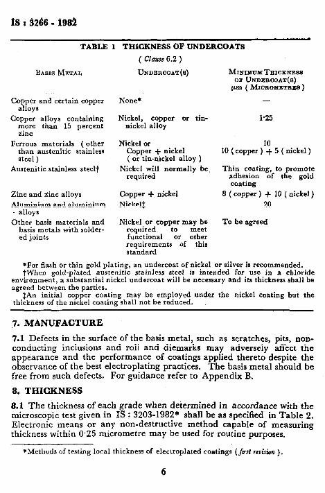
6.2 Steel and some other basis metals, should be suitably pre-coated with a deposit of nickel, copper, etc. The precise details of the type of coating and pre-plating treatment required shall be stated by the purchaser when placing order. Thickness requirements for undercoats are given in Table 1 for guidance.
5
fS t 3266 - 1981
TABLE 1 THICKNESS OF UNDERCOATS
BASIS METAL
Copper and certain copper alloys
Copper alloys containing more than 15 percent iinc
Ferrous materials ( other than austenitic stainless steel )
Austenitic stainless steel?
Zinc and iinc alloys
Aluminium and aluminium . alloys
Other basis materials and basis metals with solder- ed joints
( Clause 6.2 )
UNDERCJOAT(S)
None*
Nickel, copper or tin- nickel alloy
Nickel or Copper + nickel ( or tin-nickel alloy )
Nickel will normally be required
Copper + nickel
Nickelf
Nickel or copper may be required to meet functional or other requirements of this standard
MINIMUM TEIICKNESS or UNDERO~AT(~)
pm ( MICROMETRB~ )
l-25
10 10 (copper ) + 5 ( nickel )
Thin coating, to promote adhesion of the gold coating
8 ( copper ) + 10 ( nickel ) 20
To be agreed
*For flash or thin gold plating, an undercoat of nickel or silver is recommended. tWhen gold-plated austenitic stainless steel is intended for use in a chloride
environment, a substantial nickel undercoat will be necessary and its thickness shall be agreed between the parties.
#An initial copper coating may be employed under the nickel coating but the thickness of the nickel coating shall not be reduced.
7. MANUFACTURE
7.1 Defects in the surface of the basis metal, such as scratches, pits, non- conducting inclusions and roll and diemarks may adversely affect the appearance and the performance of coatings applied thereto despite the observance of the best electroplating practices. The basis metal should be free from such defects. For guidance refer to Appendix B.
8. THICKNESS
8.1 The thickness of each grade when delermined in accordance with the microscopic test given in Is : 3203-1982* shall be as specified in Table 2. Electronic means or any non-destructive method capable of measuring thickness within 0.25 micrometre may be used for routine purposes.
*Methods of testing local thickness of electroplated coatings (jir~t rcu&n ).
6

IS : 3266 - 1982
TABLE 2 GRADES OF GOLD PLATING
( Clause 8.1 )
GRADE MINIMUM THICICNE~S pm ( MICROMETRES )
Au 20 20
Au 15 15
Au 10 10
Au 5 5
Au 2.5 2.5
Au 0.5 0.5
9. HARDNESS
9.1 The following combination of purity and hardness range are repre- sentative of good commercial practice. For determination of knoop hardness, reference may be made to IS : 9530-1980*.
Tybe (see 4.1 ) Knoob Hardness Range
1 and 2 90 HK 25 Max
f 91-139 HK 25 3 i
i 130-20;HK 25
f 91-129 HK 25
4 and 5 i 130-2:;HK 25
i 1 Over 2”db HK 25
10. ADHESION
10.1 Adhesion Test - Gold coating shall satisfy either of the following adhesion tests as specified by the purchaser.
19.1.1 Burnishing Test - Rub an area of not more than 6 cm* of the significant surface, selected at the discretion of the inspector, rapidly and firmly for 30 seconds with a suitable burnishing tool. An agate dental spatula with a handle 60 to 100 mm long and agate blade 30 to 50 mm long, 5 to 10 mm wide, sharpened to an edge similar to a cold chisel but slightly radiused ( to avoid sharp edges ) has been found very satisfactory. Apply a pressure sufficient to burnish the coating metal at every stroke, but not so great as to cut the coating.
*Methods of testing micro hardness of electroplated coatings.
7

ISt3266-1982
10.1.2 Adhesive Tage Test - Using a straight edge and hardened steel scriber which has been ground to a sharp point, scrib a a grid of 2 mm side squares over the test area. Apply a pressure sufficient to cut through the coating to the basis metal in a single stroke.
NOTE-This test readily detects gross defects of adhesion.
10.1.2.1 Then apply the adhesive side of a non-transferable adhesive tape, with an adhesion value of 2’9 to 3.1 N per centimetre of width ( cellulose regenerated type) to the plating under test by finger pressure, taking care to exclude all air bubbles. After an interval of 10 scriber, remove the tape by applying a steady pulling force on the tape, perpendicular to the surface of the plating under test.
10.1.3 Thermal Shock Test - Raise the temperature of the sample to 200 to 300°C in air over a period of approximately 30 minutes, hold at this temperature for 10 to 60 minutes and cool by immersion in water at ambient temperature. Examine the coating for signs of blistering or detachment under a magnification of 8X.
NOTE-The temperature to which the sample should be heated and the duration over which this temperature should be maintained should be established for the coating/substrate combination being tested.
10.1.4 Bend Test -Place the sample in a bend testing machine with a bending radius of 4 mm ( or in the jaws of a suitable vice ). Bend the sample as far as 90” backwards and forwards. For the purpose of this test, one bend shall constitute bending to 90” and back to its original position. Make three bends and check the coating for signs of detach- ments.
11. SOLDERABILITY
11.1 If specified, gold coatings shall be subjected to a solderability test. The form of test should have no artificial ageing treatment carried out before the test and shall be appropriate to the intended surface of the electroplated product and details shall be agreed to between the parties.
l!.l.l A surface is considered solderable and acceptable for electrical connection purposes if 95 percent of the cooled solder surface is uniform and free from breaks and pinholes. The other 5 percent of the cooled solder surface may show only pinholes voids, dewetted areas, or rough spots that are not concentrated in one area.
12. HEAT TREATMENT
12.1 Where so specified by the purchaser, plated articles of steel with a nominal tensile strength of not less than 1 000 MPa ( or of equivalent hardness ) shall be heat-treated in order to relieve hydrogen embrittle- ment. In such cases the process from the initial cleaning of the steel part
8
to the final heating shall be carried out as quickly as possible and the articles shall not be subjected to stress prior to the final heating operation. Details concerning a heat-treating schedule for steel articles are given in Appendix C.
13. POROSlTY AND CORROSION RESISTANCE
13.1 Porosity Test - The gold coating shall withstand immersion for one minute in a solution prepared with one volume of concentrated nitric acid ( rd 1.42 ) and two volumes of water without any visible signs of chemical reactions. 13.2 Unless otherwise agreed to plating shall be tested by one of the corrosion tests given in Appendix D.
14. MARKING
14.1 Gold plated articles shall be marked with the grade, purity of the coating and name or trade-mark of the manufacturer.
14.1.1 Gold plated articles may also be marked with the IS1 Certifica- tion Mark.
NOTE - The use of the IS1 Certification Mark is governed by the provisions of the Indian Standards Institution ( Certification Marks ) Act and the rules and regulations made thereunder. The IS1 Mark on products covered by an Indian Standard conveys the assurance that they have been produced to comply with the requirements of that standard under a well-defined system of inspection, testing and quality control which is devised and supervised by IS1 and operated by the producer. IS1 marked products are also continuously checked by IS1 for conformity to that standard as a further safeguard. Details of conditions under which a licence for the use of the ISI Certification Mark may be granted to manufacturers or processors, may be obtained from the Indian Standards Institution.
15. SAMPLING AND INSPECTION
15.1 Samplitig for Production Control - Statistical quality control is recommended for controlling the quality of gold plating. For this purpose it is recommended that samples for tests should be taken from a place in the plating bath where the thickness of deposit is expected to be minimum. 15.2 Sampling for Acceptance of a Lot -For the purpose of accep- tance sampling, a lot shall be divided into sub-lots consisting of 100 articles or part thereof, of such articles are electroplated at one time in the same bath. Two samples shall be selected from each sub-lot and subjected to the appropriate tests as specified in the standard.
15.2.1 Criteria for Acceptance - If these samples pass the tests, the sub- lot represented by them shall be accepted. If one or both the samples should fail, two further samples shall be selected from the same sub-lot and subjected to the tests. If these samples pass the tests the sub-lot shall be accepted. If any of the second set of samples fails in auy test, the sub- lot shall be rejected.
9
RI : 3266 - 1981
A_PPENDIX A
( Clause 4.2 )
DETERMINATION OF GOLD CONTENT
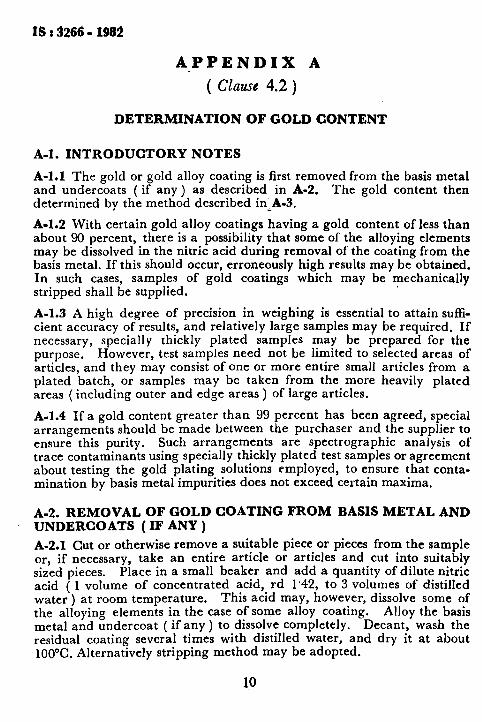
A-l. INTRODUCTORY NOTES
A-l.1 The gold or gold alloy coating is first removed from the basis metal and undercoats ( if any ) as described in A-2. The gold content then determined by the method described in&A-3.
A-l.2 With certain gold alloy coatings having a gold content of less than about 90 percent, there is a possibility that some of the alloying elements may be dissolved in the nitric acid during removal of the coating from the basis metal. If this should occur, erroneously high results may be obtained. In such cases, samples of gold coatings which may be mechanically stripped shall be supplied.
A-l.3 A high degree of precision in weighing is essential to attain s&i- cient accuracy of results, and relatively large samples may be required. If necessary, specially thickly plated samples may be prepared for the purpose. However, test samples need not be limited to selected areas of articles, and they may consist of one or more entire small articles from a plated batch, or samples may be taken from the more heavily plated areas ( including outer and edge areas ) of large articles.
A-I.4 If a gold content greater than 99 percent has been agreed, special arrangements should be made between the purchaser and the supplier to ensure this purity. Such arrangements are spectrographic analysis of trace contaminants using specially thickly plated test samples or agreement about testing the gold plating solutions employed, to ensure that conta- mination by basis metal impurities does not exceed certain maxima.
A-2. REMOVAL OF GOLD COATING FROM BASIS METAL AND UNDERCOATS (IF ANY )
A-2.1 Cut or otherwise remove a suitable piece or pieces from the sample or, if necessary, take an entire article or articles and cut into suitably sized pieces. Place in a small beaker and add a quantity of dilute nitric acid ( 1 volume of concentrated acid, rd 1’42, to 3 volumes of distilled water ) at room temperature. This acid may, however, dissolve some of the alloying elements in the case of some alloy coating. metal and undercoat ( if any ) to dissolve completely.
Alloy the basis Decant, wash the
residual coating several times with distilled water, and dry it at about lt)()°C. Alternatively stripping method may be adopted.
10
18 t 3266 - 1981
A-3. FlRE ASSAY
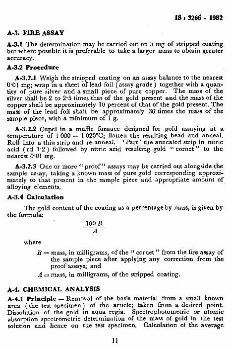
A-3.1 The determination may be carried out on 5 mg of stripped coating but where possible it is preferable to take a larger mass to obtain greater accuracy.
A-3.2 Procedure
A-3.2.1 Weigh the stripped coating on an assay balance to the nearest 0.01 mg; wrap in a sheet of lead foil ( assay grade ) together with a quan- tity of pure silver and a small piece of pure copper. The mass of the silver shall be 2 to 2.5 times that of the gold present and the mass of the copper shall be approximately 10 percent of that of the gold present. The mass of the lead foil shall be approximately 30 times the mass of the sample piece, with a minimum of 1 g.
A-3.2.2 Cupel in a muffle furnace designed for gold assaying at a temperature of 1000 - 1020°C; flatten the resulting bead and anneal. Roll into a thin strip and re-anneal. g Part ’ the annealed strip in nitric acid (rd 1.2 ) followed by nitric acid resulting gold “ cornet ” to the nearest 0.01 mg.
A-3.2.3 One or more ‘( proof” assays may be carried out alongside the sample assay, taking a known mass of pure gold corresponding approxi- mately to that present in the sample piece and appropriate amount of alloying elements.
A-3.4 Calculation
The gold content of the coating as a percentage by mass, is given by the formula:
100 B -- A
where
B = mass, in milligrams, of the cc cornet ” from the fire assay of the sample piece after applying any correction from the proof assays; and
A = mass, in milligrams, of the stripped coating.
A-4. CHEMICAL ANALYSIS
A-4.1 Principle - Removal of the basis material from a small known area ( the test specimen ) of the article; taken from a desired point. Dissolution of the gold in aqua regia. Spectrophotometric or atomic absorption spectrometric determination of the mass of gold in the test solution and hence on the test specimen. Calculation of the average
11

Is t 3264 w 1982
thickness of the gold coating on the test specimen from its area and mass from the density of the gold coating.
A-4.2 Reagents - Use only reagents of recognized analytical grade and only distilled water or water otherwise obtained of equivalent purity.
A-4.3 Apparatus -Thoroughly clean all glassware, including the spectrophotometric cells, with the aqua regia ( A-4.5.1.2) and rinse with water before use. It is preferable to reserve glassware solely for use with these analyses.
A-4.4 Test Specimen - Carefully punch or cut a test specimen from the article so that its area may be measured with an accuracy of 2 percent or better and so that the mass of gold may be determined subsequently with an accuracy of 2 percent or better. It may be necessary to square off and sand the edges to remove any gold measured over the edge by the punching or cutting operation.
The accuracy of the thickness measurements depends largely on the accuracy with which the area of the test specimen is measured. For articles made from sheet materials, accurately sized test specimens may be taken conveniently by using a punch and die to give discs of known diameter. For gold electroplated pads on printed wiring boalds, the copper foil can usually be detached mechanically. If necessary, the pads may be detached from the laminate by boiling in 200 g/l sodium hydroxide solution.
The quantities of reagents and the dilutions specified in the following procedures are related to an area of 0.1 cm2, which is the smallest test specimen that should be taken. If larger areas are taken, adjust the dilutions and the volumes of the aliquot portions of the test solution accordingly.
A-4.5 Preparation of Test and Standard Solutions
A-4.5.1 Reagents
A-4.5.1.1 Nitric acid - rd. approximately 1.2, about 25 percent (m/m ) solution.
A-4.5.1.2 Aqua regia -Add 25 ml of concentrated nitric acid (rd approximately l-42 g/ml ) to 75 ml of concentrated hydrochloric acid solution ( rd approximately l-18 ). Prepare just before use.
A-4.5.2 Test Solution -Remove as much as possible of the basis material from the test specimen ( A-4.2 ) by mechanical means before stripping, in order to minimize potential attack on the gold coating. Separate the coating from the remaining basis material by dissolving the latter in the nitric acid solution ( A-4.5.1.1 ). Wash and dry the stripped
12

coating and dissolve it in 3 ml of the hot aqua regia ( A-4.5.1.i’) in a 50-ml beaker.
A-4.5.3 Standard Solutions
A-4.5.3.1 Reagent - Dissolve 0.050 g of ‘ proof’ gold, purity 99.99 percent ( m/m) in 20 ml of the aqua regia ( A-4.5.1.2 ) and dilute with water to the mark in a 1 000 ml one-mark volumetric flask.
A-4.5.3.2 Preparation of standard solutions - Into a series of six of the 50 ml beakers ( A-4.6.3.2 ), place the volumes of the standard gold sol+ tion ( A-4.5.3.1 ) shown in Table 3.
NOTE -For lower ranges of thickness, dilute the standard gold solution five fold.
TABLE 3 STANDARD SOLUTIONS
Vo~unnso~ STANDARD CORRESPONDINQ CONCENTRATIONOBGOLD GOLDSOLUTION MASSOF GOLD INFINAL SOLTJTIO~ (A-4.5.3.1 )
ml mg mg/ml o*
1-o
2.0
4.0 6.0 8.0
*Compensation solution.
0* 0' 0.05 o-005
0.10 O*OlO
0.20 0.020 0.30 0*030 0.40 o-040
A-4.6 Spectrophotometric Method
A-4.6.1 Princi$lc - Addition of potassium chloride to the test solution to give stable gold potassium chloride. Evaporation to dryness and spectrophotometric determination of the gold content.
Basis metals that have soluble colourless chlorides and copper, nickel, cobalt and iron, that have coloured chlorides, do not interfere. The method is, therefore, suitable for gold coatings containing such metals. In the case of gold coatings containing alloying metals, such as, silver, that have chlorides, it may be necessary to filter the solution before measuring the absorbance.
A-4.6.2 Reagents
A-4.6.2.1 Potassium chloride - 10 g/l solution.
A-4.6.2.2 Hydrochloric acid - 20 percent ( v/v ) solution. Dilute 200 ml of concentrated hydrochloric acid solution ( rd approximately 1.18 ).
13

tS : 3266 - 1982
A-4.6.3 Apparatus - Ordinary laboratory apparatus.
A-4.6.3.1 S’ectrophotometer - Fitted with 10 mm and 40 mm silica cells.
A-4.6.3.2 Beakers - 50 ml capacity, squat form. At least six are required.
A-4.6.3.3 Micro-jilter funnel_- fitted with a sintered glass filter plate or a suitable filter-stick.
A-4.6.3.4 Electric own - capable of being maintained at 110 f 2°C.
A-4.6.4 Prefiaration of Calibration Graph
A-4.6.4.1 Preparation of standard calorimetric solutions - Treat the contents of each beaker of standard solution ( A-4.5.3.2 ) as follows:
Add 1 ml of the potassium chloride solution ( A-4.6.2.1 ), evaporate carefully to incipient dryness on a hot-plate or water bath, dry in the oven ( A-4.6.3.4 ), maintained at 110 f 2”C, and allow to cool. Redissolve the residue in 10 ml of the hydrochloric acid solution ( A-4.6.2.2 ).
A-4.6.4.2 Spectrophotometric measurements- Carry out the spectrophoto- metric measurements of the standard calorimetric solutions in the spectro- photometer (A-4.6.3.1 ) at a wavelength of 312 nm and using 10 mm cells, after having adjusted the instrument to zero absorbance against water.
A-4.6.4.3 Plotting the calibration graph - Deduct the absorbance of the compensation solution from those of the standard calorimetric solu- tions, Plot a graph of the concentrations, in milligrams of gold per millilitre, as abscissae against the corresponding net values of absorbance as ordinates. A straight line should be obtained.
A-4.6.5 Determination - Carry out the determination in duplicate, starting from two different test specimens ( A-4.4 ). Add 1 ml of the potassium chloride solution ( A-4.6.2.1 ) to the test solution ( A-4.5.2) and evaporate carefully to incipient dryness on a hot-plate of water bath. Dry in the electric oven ( A-4.6.3.4 ), maintained at 110 f 2°C and allow to cool. Redissolve the residue in the hydrochloric acid solution ( A-4.6.2.2 ) in a one-mark volumetric flask of capacity indicated in Table 4, and dilute to the mark with the same acid.
Measure the absorbance of the solution in the spectrophotometer ( A-4.6.3.1 ) at a wavelength of 312 nm and using the appropriate cell
Sndicated in Table 4, after having adjusted the instrument to zero absorbance against the blank test solution ( A-4.6.6 ).
14

!$ : 3266 - i981
TABLE 4 VOLUMES OF DILUTION AND CELL SIZES FOR VARIOUS THICKNESSES OF COATING
( Clause A-4.6.5 )
APPROXIMATE COATING CapAaITY OP ONE-MABK CELL SIZE THICKNESS VOLUYETIZIo FLASK
pm ml mm
5-o to 10.0 20 Id
l-25 to 5.0 10 10
o-1 to 1.25 10 40
A-4.6.6 Blank Test -Carry out a blank test at the same time as the determination, following the same procedure and using the same quanb tities of all the reagents, but omitting the test specimen.
A-4.7 Atomic Absorption Spectrometric Method
A-4.7.1 Principle - Addition of lanthanum chloride to the test solution to suppress interferences and measurement of the atomic absorption.
A-4.7.2 Lanthanum chloride - approximately 100 g/l solution.
Dissolve approximately 58.6 g of lanthanum oxide in 250 ml of concentrated hydrochloric acid (rd approximately 1.18) and dilute to 500 ml with water.
A-4.7.3 Apparatus - Ordinary laboratory apparatus.
A-4.7.3.1 Atomic absorption spectrometer
A-4.7.4 Preparation of Calibration Graph
A-4.7.4.1 Preparation of standard matching solutions-Treat the contents of each beaker of standard solution ( A-4.5.3.2 ) as follows:
Transfer to a series of six loo-ml one-mark volumetric flasks, add 4 ml of the lanthanum chloride solution ( A-4.7.2.2) and dilute to the mark with water.
A-4.7.4.2 Spectrometric measurements - Aspirate the standard matching solutions (A-4.7.4.1 ) directly into the flame of the atomic absorption spectrometer ( A-4.7.3.1 ), using the conditions for gold determination specified by the instrument manufacturer, and record the absorbance readings.
,.
A-4.7.4.3 Plotting the calibration graph - Deduct the absorbance of the compensation solution from those of the standard matching solutions. Plot a graph of the concentrations, in milligrams of gold per millilitre, as abscissae against the corresponding net values of absorbance as ordinates.
15

& t 3266 - 1982
A-4.7.5 Determination - Transfer the test solution (A-4.5.2 ) to one- mark volumetric flask of capacity indicated in Table 5, add the indicated volume of the lanthanum chloride solution ( A-4.7.2.1 ) and dilute to the mark,
TABLE 5 VOLUMES OF DILUTION AND OF LANTHANUM CHLORIDE SOLUTION FOR VARIOUS MASSES OF GOLD
MASS OF GOLD IN CAPACITY OF ONE-MARK VOLUME: or LANTHANUM TEST SPECIMEN VOLUMETRIC FLASK CHLORIDE SOLUTION
mg ml ( A-4.7.2.1 ), ml
up to 02 10 o-4
Over 0.2 to 2 100 4
Over 2 to 20 1000 40
Measure the absorbance of the resultant solution as described in A- 4.7.4.2.
A-4.8 Calculation - The average coating thickness, in micrometres, is given by the expression.
ml x 10 100 Ax-X
where
mr = mass, in milligrams, of gold in the test solution, calculated from the calibration graph ( A-4.6.4 or A-4.7.4 ) and the total volume of the final test solution ( see Tables 4 and 5 );
A = area, in square centimetres, of the test specimen ( A-4.4 ); rd = density, in grams per cubic centimetre, of the coating; and P = gold content, expressed as a percentage by mass of the
coating (see Appendix A-3.2 ).
APPENDIX B ( Clause 7.1 )
GUIDELINES FOR OBTAINING GOOD FINISH OF GOLD ELECTROPLATING
&l. REMOVAL OF SURFACE DEFECTS OF THE BASIS METAL
B-l.1 In order to minimize problems of this sort, the specifications covering the basis material or the item to be coated should contain appropriate limitations on such basis metal conditions.
R-l.2 Ferrous parts having a hardness greater than 48 HRC ( Rockwell h6bsl$ness Cl) shall not be plated.
16
tS:9266-X982
B-1.3 Such material shall be given the same heat treatment before cleaning and electroplating operations as well as after the electroplating step. The temperature may be modified, if required in order to obtain the maximum stress relief without a reduction in hardness.
NOTE -The quality and serviceability ( including the porosity ) of the gold coatings are largely affected by the physical and chemical nature of the basis metal surface. It is, therefore, essential that the surface of the substance be as smooth and free from scratches, gouges, nicks and similar imperfections as possible and that it be chemically clean.
When electroplated parts are to be used for electrical contacts, cleaning alone may not properly preparelthe surface for gold electroplating. If the basis metal is scratched or rough, it may be necessary to level the surface by processes such as electropolishing, chemical polishing or the application of a self-levelling nickel or copper undercoating before gold electroplating. However, the use of these under- coatings requires the approval of the purchaser.
B-l.4 Proper preparatory procedures and thorough cleaning of the basis metal are essential for satisfactory adhesion and performance of these coatings. Surface shall be chemically clean and continuously conductive that is without insulating inclusions, impurities or contaminants.
B-1.5 Most gold electroplating solutions used for producing these coatings are proprietary. Any bath that produces coatings meeting the require- ments of this specification may be used.
B-l.6 Goid Electroplating - Care should be exercised to prevent con- tamination of gold electroplating solutions with organic or metallic impurities which may impair the quality of the finished product. Copper, zinc and cadmium ( from racking materials, bus bars, etc ), iron ( from 6 insoluble ’ anodes ), lead and tin ( from soldered parts ), and silver ( from impurities in the bath make up salts ) are some of the more common contaminants, which if present in the coating in more than trace quantifies may have harmful effects on such properties as hardness, solderability and porosity.
B-1.6.1 Periodic treatment of the solution with activated carbon is recommended to control the build-up of organic impurities. This contamination has the effect of reducing the maximum current density usable without discoloration of the deposit. Thus, the appearance of test coupons plated at an appropriate, higher than normal current density may serve as an indication of an approaching need for the activated carbon treatment.
B-l.7 Control of the Gold Electroplating Bath - Under continuous operations, when control of bath composition may be readily established by scheduled additions, analysis of the electroplating bath need be made only two or three times a week. When the work load is erratic, each addition shall be based on an actual analysis.
17

1s :‘3!266 - 1982
APPENDIX C
( Clause 12.1 )
HEAT-TREATMENT OF PLATED ARTICLES
C-l. HEAT TREATMENT
C-l.1 For the relief of hydrogen embrittlement, articles made of steel of a minimum specified tensile strength in the range of 100 to 1 000 MPa to 1400 MPa other than springs or articles surface-hardened ( but including those nitrided ), should be baked at 200 f 10°C for not less than 4 hours.
C-l.2 Surface-hardened steel articles with a hardness value greater than 55 HRC ( Rockwell hardness C ) or its equivalent Vickers hardness, should be baked at 135 j, 10°C for not less than 4 hours. Surface hardened steel articles with a value less than 55 HRC should be baked at 200 f 10% for 4 hours or for such period and at such temperature as may be determined by agreement.
NOTE - In the case of components where the requirements are more critical than normal ( for example, aircraft components ), steels with a specified minimum tensile strength greater than 140 MPa may be needed. Where the tensile strength of such steels is greater than 1400 MPa but less than 1850 MPa, the steels should be heat-treated in the temperature range of 190 to 210% for not less than 18 hours. Where the specified tensile strength exceeds 1850 MPa, the heat treatment should be for not less than 24 hours in the temperature range 190 to 210°C.
G1.3 Steel springs should be heat-treated at 200 f 10% for not longer than 24 hours. Spring ratings may be affected if this temperature is exceeded.
APPENDIX D ( Clause 13.2 )
CORROSION TESTS
D-I. GENERAL
D-l.1 Electroplated gold and gold alloy coatings for engineering purposes are required to retain over long periods of storage or use the ability to perform the functions they serve, Among these functions are low contact resistance, easy solderability and the provision of a stable surface suitable for carrying high-frequency currents. result from:
Impairment of performance may
4
b)
corrosion of basis metal or of undercoat metal exposed at dis- continuities in the gold coating, with the formation of corrosion products as a thin general layer; and for some alloys of lower gold content, the formation of corrosion products of the alloying elements as a layer over the surface.
18

D-l.2 It is possible to obtain direct indications of porosity by use of the. tests described in 12.1. However, it is often more convenient, especially for articles of complex shape, to reveal the pore sites and to develop corrosion products more likely to resemble those produced in service by exposing test specimens to a humid atmosphere polluted with a gas or vapour able to react with basis metal or undercoat exposed at pores in the gold coating.
D-1.3 Two tests are proposed, one using atmospheres containing sulphur dioxide, and the other one using nitric acid vapour. The effect produced will depend on the nature ofthe metal exposed at discontinuities in the gold coating. Sulphur dioxide is a general purpose medium producing visible effects for exposure of any basis metal or undercoat, although the effects are not always well marked for substrates or undercoats or silver.
D-1.3.1 Nitric acid vapour gives indications for copper, brass and nickel substrates or undercoats but is not useful for silver. Any effect on the coating itself will depend on the nature and amount of alloying elements. The test chosen should be capable of revealing the exposure of the basis metal or any of the undercoats. For general purposes it <has not been considered necessary to include a test during which a correctly applied undercoat metal is likely to be penetrated. The thickness of undercoats specified should be an adequate safeguard against penetration of corrosion to the basis metal in normal service but it is suggested that when exceptionally severe conditions have to be met, special tests should be agreed upon.
D-l.4 The properties of the corrosion products produced during the tests differ from the products formed in actual environments, and the tests are not recommended for evaluation of the electrical performance of contacts unless correlation is first obtained with service experience. There is some evidence that the “Industrial atmosphere test ” ( D-3. ) may permit such a correlation to be obtained rather more readily than do the other tests, .However, this test requires much more elaborate apparatus for its correct operation.
D-l’.5 The tests suggested are applicable to articles of any size smaller than about 100 x 100 mm. Specimens shall be degreased in trichlore- thylene vapour or other suitable solvent before the test. Any cut edge or other unplated substrate shall be protected during the test.
D&2. SULPHUR DIOXIDE EXPOSURE TEST”
D-2.1. This test is suitable for application with all undercoats and sub- strates. The generation of sulphur dioxide from known reagents inside
*Attention is drawn to the toxic hazards of sulphur dioxide; the test vessels, at least during filling and opening, should be placed under a suitable extraction hood.
19.

tS t 3266 - 1962
the test vessel permits an easy control of the atmosphere composition. A suitable test vessel is a container made of glass or acrylic resin of about 10 1 capacity, capable of being closed by a gas-tight cover or door. A conventional 10 1 desiccator vessel is recommended. Provision shall be made for the support of test specimens within the vessel so that they are about 100 mm above its base. The specimens may be suspended from rods by means of suitable material, for example, nylon thread or glass. hooks. All materials used for chamber construction or specimen support shall be non-metallic and inert to the action of sulphur dioxide; glass and acrylic resin are suitable materials.
D-2.1 The test temperature shall he maintained within a temperature range agreed as being suitable for the materials under test and for a selected duration of test.
b-2.2 During the progress of the test, the test vessels shall be kept screened, from draughts or from any source of local radiant heat so that sudden temperature fluctuations and local heating of the test chamber are
3 avoided,
D-2.3 Introduce 200 ml of a 200 g/l sodium thiosulphate soiution into the test chamber and add to it 50 ml of 50 percent ( V/V) sulphuric acid ( rd 1.84 ). Place the test specimens immediately in the vessel so that they are not less than 75 mm above the surface of the liquid and not less than 25 mm from the walls. Close the vessel immediately and move it gently to ensure complete mixing of the two solutions,
D-2.4 After expiry of the test period, open the test chamber, remove and inspect the test specimens. Two recommended test period are 24 hours at 25 & 5°C and 2 hours at 60 & 3°C.
D-3. INDUSTRIAL ATMOSPHERE TEST
D-3.1 A test cabinet with a capacity of about 200 1 is provided with a means of moving test specimens through the test atmosphere at 11 f 3 mm/s. The test atmosphere, maintained at 25 f 2”C, contains sulphur dioxide, 25 f 5 ppm ( V/V), with a relative humidity as close as possible to 75 percent and within the range 70 to 80 percent.
D-3.2 The test atmoshpere shall flow through the chamber at a rate sufl+ient to produce 3 to 5 changes of atmosphere per hour. It may be generated either by mixing directly the necessary constituents or by burn- ing propane, butane or natural gas with a controlled addition of carbon disulphide and adjusting the resulting combustion product to the required composition by additions of air and water vapour.
20

IS: 326611982
D-3.3 When the object of testing is to determine any increase in contact resistance, the test piece will usually be samples taken from finished products and contact resistance will be measured before and after test.
D-4. NITRIC ACID TEST
D-4.1 The test chamber requirements are similar to those described for ’ the sulphur dioxide test in B-2 except that only glass may be used as the material of construction and as specimen supports. The chamber volume expressed in cubic centimetres shall not be more than 25 times the nitric acid surface expressed in square centimetres Accurate temperature control is not essential but a test temperature of 23 f 3°C is recommended.
D-4.2 The solution used is 69 to 71 percent ( m/m ) nitric acid ( rd 1,415 to 1..420 ).
D-4.3 The required quantity of nitric acid is added to the test chamber, which is then closed. After 30 minutes, the cover is carefully lifted, the test samples are introduced and the cover is replaced, Unless otherwise specified, the test duration is 60 _I: 10 minutes for gold coatings on copper or copper alloys and 120 f 10 minutes for nickel substrates and under- coats.
D-4.4 At the end of the test, the samples are removed and dried in an oven at 125°C for 30 minutes. The surface is then examined at IOX magni- fication. The solids may be transparent in the case of gold plated nickel and it is recommended that the illumination used for the examination of the samples should make it possible to see the corrosion products as protrusions from the pore sites; for example, a collimated beam at an oblique angle below I5O may be used.
D-4.5 The nitric acid is discarded after each test. Tests should be carried out under an extraction hood since the gases released when the test vessel is opened at the end of the test may be harmful to health.
D-4.6 The test is not recommended for gold coatings on silver or with substrates for which a silver undercoating is used. Caution is necessary in the application of the nitric acid test to high strength gold alloys, parti- cularly those containing over 10 percent copper, since stress corrosion cracking may produce an apparent increase in defects.
21

INDIAN STANDARDS
ON
ELECTROPLATING
IS:
1067-1981
10681968
1337-1980
1359-1977
13781979
1572-1968
1573-1970
1771-1970
1772-1972
1773-1961
1992-1979
4827-1968
4828-1968
4942-1968
8376-1977
Electroplated coatings of silver for decorative and protective purposes ( jirsf revision )
Electroplated coatings of nickel and chromium on iron and steel (first revision )
Electroplated coatings of hard chromium on iron and steel ( srcond revision )
Electroplated coatings of tin ( second revision )
Oxidized copper finishes ( second resision )
Electroplated coatings of cadmium on iron and steel (JFrst revision )
Electroplated coatings of zinc on iron and steel (first revision )
Electroplated coatings of silver for general engineering purposes (first reuision )
Electroplated coatings of copper (first revision )
Brass plating
Electroplated coatings of lead (first revision )
Eiectroplated coatings of nickel and chromium on copper and copper alloys
Electroplated coatings of nickel and chromium on aluminium and alumi- nium alloys
Electroplated coatings of nickel and chromium on zinc and zinc alloys
Electroplated coatings of nickel and chromium on plastics for decorative purposes