Embed Size (px)
Citation preview
MANUALE DI SERVIZIOSERVICE MANUAL
COD.MS_IS38
mase
mase
mase
mase
mase
GE
NE
RA
TO
RS
IS 3.8 - IS 7 - IS 10IS 4.5 - IS 8 - IS 11.5
50 Hz
60 Hz

INDEX
1.0 Technical features1.1 IDENTIFICATION OF GENERATOR
GENERATOR SERIAL NUMBERENGINE SERIAL NUMBER
1.2 IDENTIFICATION OF COMPONENTS
2.0 Power generation principleand A.V.R.
3.0 Maintenance3.1 NOTES ON SERVICE3.2 PERIODIC SERVICE GUIDE
4.0 Service4.1 INSPECTIONS POSSIBLE WITHOUT
HAVING TO DISMOUNT THEALTERNATOR, DIRECTLY ON THEBRANCH BOX
4.1.1 Excitation winding4.1.2 Power winding4.1.3 Battery charger winding4.1.3.1 Battery charger fuse and wiring fuse4.1.4 Thermal switch4.1.5 Control board4.1.5.1 Fuse4.1.45.2 Relay4.1.5.3 Diodes4.2 ROTOR4.2.1 Rotor winding4.3 ALTERNATOR
DISMOUNTING/MOUNTING4.4 CONTROL PANEL4.4.1 Printed circuit4.4.2 Remote control panel4.5 OTHER COMPONENTS4.5.1 Heat exchanger (water/air)4.5.1.1 Tube nest4.5.1.2 Zinc anodes4.5.2 Other components4.5.2.1 Fuel - Solenoid IS 3.8-4.54.5.3 Stop solenoid4.5.4 Engine speed adjustement4.5.5 Water temperature switch4.5.6 Oil pressure switch4.5.7 Starter
5.0 Trouble shoooting
6.0 Machine wiring diagram6.1 CONTROL PANEL WIRING DIAGRAM
AND CONNECTION
INDICE
1.0 Caratteristiche tecniche1.1 IDENTIFICAZIONE DEL GENERATORE
NUMERO DI MATRICOLA DELGENERATORENUMERO DI MATRICOLA DEL MOTORE
1.2 IDENTIFICAZIONE DEI COMPONENTI
2.0 Principio di funzionamento eregolazione elettronica dellatensione
3.0 Manutenzione3.1 GENERALITÀ3.2 TABELLA DI MANUTENZIONE
4.0 Controlli4.1 CONTROLLI CHE POSSONO ESSERE
ESEGUITI SENZA SMONTAREL'ALTERNATORE
4.1.1 Avvolgimento di eccitazione4.1.2 Avvolgimento di potenza4.1.3 Avvolgimento di carica batteria4.1.3.1 Fusibile carica batteria più fusibile cablaggio4.1.4 Interruttoretermico4.1.5 Scheda comandi4.1.5.1 Fusibile4.1.5.2 Relay4.1.5.3 Diodi4.2 ROTORE4.2.1 Avvolgimento di rotore4.3 SMONTAGGIO/MONTAGGIO
ALTERNATORE4.4 CRUSCOTTO COMANDI4.4.1 Circuito stampato4.4.2 Comando distanza4.5 ALTRI PARTICOLARI4.5.1 Scambiatore di calore (acqua/aria)4.5.1.1 Fascio tubiero4.5.1.2 Anodi di zinco4.5.2 Controlli su altri particolari4.5.2.1 Elettromagnete - Stop IS 3.8-4.54.5.3 Elettrovalvola4.5.4 Regolazione dei giri4.5.5 Termostato acqua4.5.6 Pressostato olio4.5.7 Motorino avviamento
5.0 Tabella guasti
6.0 Schema elettrico macchina6.1 SCHEMA ELETTRICO DI
COLLEGAMENTO PANNELLO

1.0Caratteristiche tecniche - Technical features
Tipo - Type
YANMAR
1 GM 10 L - G2
2 GM FL - 42
3 G MF - 42
Alesaggio - Bore
MM. (inch)
75 (2,95)
Corsa - Stroke
MM. (inch)
72 (2,83)
Cilindrata - Displacement
CC. (CU. inch.)
318 (6,15)
636 (12,31)
954 (18,47)
Potenza - Power NB (DIN 6270)
HP (KW)
6,5 (4,8)
7,8 (5,7)
12 (8,8)
14,5 (10,6)
18,5 (13,6)
22 (16,2)
Potenza - Power NA (DIN 6270)
HP (KW)
6,0 (4,4)
7,0 (5,1)
11 (8,1)
13,0 (9,60)
17,0 (12,5)
20 (14,7)
Giri - R.P.M.
3000
3600
3000
3600
3000
3600
Rapporto compress. - Compress. ratio
23/1
Numero cilindri - Number of cylinders
12
3
Capacità olio basamento - Oil sump capacity
KG (LT.)
1 (1,3)
1,6 (2)
2,1 (2,6)
Capacità scambiatore calore - Heatexchanger capacity
L. (U.S.G.)
2,9 (0,76)
3,4 (0,9)
Capacità vaso espansione - Recovery tank capacity
L. (U.S.G.)
0,8 (0,2)
MOTORE - ENGINE
Lunghezza - Lenght
770mm.
950
mm.
1060
mm.
Larghezza - Width
550 mm.
550
mm.
550
mm.
Altezza - Height
560 mm.
630
mm.
630
mm.
Peso - Weight
132
Kg.
190
kg.
230
kg.
DIMENSIONI - DIMENSIONS
Modello - Model
IS3,8 50 HZ.
4,5 60 HZ.
7 50 HZ.
8 60 HZ.
10 50 HZ.
11,5 60 HZ.
Tipo
Sincrono - monofase - autoeccitato con regolatore elettronico
Type
Synchronous - single phase - self exciting with A.V.R.
Potenza max. - Max. power
W3800
4500
7000
8000
10000
11500
Potenza continuativa - Cont. power
W3500
4000
6500
7300
9200
10000
Fattore di potenza otenza - Power factor
1
Classe isolamento - Insulation class
F
ALTERNATORE - ALTERNATOR

1.1 IDENTIFICAZIONE DELGENERATORE
1.1 IDENTIFICATION OF GENERATOR
Fig. 1
IS 3.8/4.5
Il numero di matricola del generatore è riportatosu di un adesivo, posto sulla parte inferiore dellacassa (Fig. 1/1a).Qualora non sia possibile identificare il generato-re da questo numero, si faccia riferimento alnumero di matricola del motore, punzonato sullatarghetta (Fig. 2/2a).
Each generator has got an identification numberindicated on a sticker on the lower front side of thesound shield (Fig. 1/1a).In case identification trough this number becomesimpossibile, please refer to the engine number,marked on the label (Fig. 2/2a).
Fig. 1a
IS 7/8-10/11.5
Fig. 2aFig. 2
IS 3.8/4.5 IS 7/8-10/11.5

1.2 IDENTIFICATION OF COMPONENTS1.2 IDENTIFICAZIONE DEI COMPONENTI
Fig. 3
IS 3.8/4.5
Fig. 4
IS 3.8/4.5
Elementi della macchina (Fig. 3-4)
1) Motore2) Alternatore3) Scatola di derivazione4) Filtro gasolio5) Interruttore alta temperatura acqua6) Filtro aria7) Valvola termostatica8) Rubinetti scarico acqua9) Elettromagnete di arresto10) Pompa combustibile11) Pompa acqua12) Pressostato olio13) Pastiglie di zinco14) Ingresso combustibile15) Ritorno combustibile16) Ingresso acqua17) Morsetti batteria18) Scambiatore acqua/aria19) Presa aria20) Passacavi21) Raccordo scarico
Generator components (Fig. 3-4)
1) Engine2) Alternator3) Junction box4) Fuel filter5) High water temperature switch6) Air filter7) Thermostatic valve8) Water discharge tap9) Safety stop electromagnet10) Fuel pump11) Water pump12) Oil pressure switch13) Zinc anodes14) Fuel feed15) Fuel return16) Water inlet17) Battery connections18) Water/air heat exchanger19) Air inlet20) Cables guide21) Exhaust fitting
11
7
1214
10
8
21
9
16
1
4
18
13
2
615
5
17
20
19
3

IS 7/8-10/11.5 IS 7/8-10/11.5
Fig. 6
Elementi della macchina (Fig. 5-6)
1) Motore2) Alternatore3) Scatola di derivazione4) Filtro gasolio5) Interruttore alta temperatura acqua6) Filtro aria7) Valvola termostatica8) Scambiatore calore9) Rubinetti scarico liquido refrigerante10) Elettrovalvola di arresto11) Leva arresto manuale12) Pompa combustibile13) Pompa acqua14) Pressostato olio15) Pastiglie di zinco16) Ingresso combustibile17) Ritorno combustibile18) Ingresso acqua19) Collegamenti batteria20) Presa aria21) Passacavi22) Scambiatore acqua/aria23) Raccordo scarico
Generator components (Fig. 5-6)
1) Engine2) Alternator3) Junction4) Fuel filter5) High water temperature switch6) Air filter7) Thermostatic valve8) Heat exchanger9) Coolant discharge tap10) Fuel solenoid11) Manual stop lever12) Fuel pump13) Water pump14) Oil pressure switch15) Zinc anodes16) Fuel feed17) Fuel return18) Water feed19) Battery connections20) Air inlet21) Cables guide22) Water/air heat exchanger23) Exhaust fitting
Fig. 5
17
6
19
3
20
1
22
2
15
8
18
16
21
11
75
10
14
13
4
923
12

Fig. 8
Collegamenti (Fig. 8)
1) Morsettiera di potenza2) Regolatore ricarica batteria3) Regolatore di tensione4) Portaspazzole5) Morsettiera regolatore di tensione
Connection (Fig. 8)
1) Power terminal board2) Battery charger regulator3) A.V.R.4) Brush holder5) A.V.R. terminal board
Scheda relè (Fig. 7)
1) Morsettiera cruscotto comandi2) Scheda relè3) Fusibile carica batteria (30 A)4) Fusibile (30 A)5) Fusibile protezione scheda (1 A)
Relay board (Fig. 7)
1) Control panel terminal board2) Relay board3) Battery charger fuse (30 A)4) Fuse (30 A)5) Relay board fuse (1 A)
Fig. 7
512
34
3
1
2
5
4

CRUSCOTTO COMANDI CONTROL PANEL
1) Contaore2) Connettore allacciamento comando distanza3) Pulsante «ON»4) Pulsante «START»5) Pulsante «OFF»6) Spia pressione olio7) Spia temperatura acqua8) Spia sovraccarico/sovratemperatura9) Spia alimentazione cruscotto10) Spia generatore11) Circuito stampato
1) Hoursmeter2) Remote control panel connector3) «ON» push-button4) «START» push-button5) «OFF» push-button6) Oil pressure lamp7) Water temperature lamp8) Overload/overtemperature lamp9) Control panel lamp10) Generator lamp11) Printed circuit
Fig. 9
116
7
8
10
21
93
45

PANNELLLO A DISTANZA REMOTE CONTROL PANEL
Remote control panel (Fig. 10)
1) «ON» push-button2) «START» push-button3) «OFF» push-button4) General warning lamp5) Remote control panel lamp
WARNINGWhen the remote control panel is connected,automatically the start and stop functions onthe main control panel are cutted out.
Comando a distanza (Fig. 10)
1) Pulsante «ON»2) Pulsante «START»3) Pulsante «OFF»4) Spia allarme generale5) Spia alimentazione comando6) Spia funzionamento generatore
IMPORTANTEL’allacciamento del cruscotto comandi a distan-za esclude automaticamente i comandi avvia-mento e arresto dal cruscotto comandi princi-pale.
Fig. 10
5
4
6
3
21

2.0 Principio di funzionamentoe regolazione elettronicadella tensione
2.0 Power generation principleand A.V.R.
I generatori della serie I.S. sono dotati di alterna-tori, sincroni, a due poli, con regolazione elettro-nica.Lo statore (Fig. 11, Rif. 2) alimenta il regolatoreelettronico (Fig. 11, Rif. 3) tramite un avvolgimentodi eccitazione separato (Fig. 11, Rif. 4).Il regolatore elettronico provvede ad alimentare ilrotore (Fig. 11, Rif. 1) attraverso le spazzole (Fig.11, Rif. 5) inviando una corrente continua variabi-le in funzione del carico per mantenere costantela tensione in uscita.La tensione di uscita è regolabile agendo sulpotenziometro (Fig. 12, Rif. 1) del regolatore elet-tronico.
IS series generators are equipped with two polesynchronous alternators with electronic regulation.The stator (Fig. 11, Ref. 2) powers the electronicregulator (Fig. 11, Ref. 3) by means of a separateexciter winding (Fig. 11, Ref. 4).The electronic regulator poloers the rotor (Fig. 11,Ref. 1) by means of the brushes (Fig. 11, Ref. 5),sending them a direct current varying in relation withthe load in order to maintain the output voltageconstant.
The output voltage is adjustable turning thepotentiometer (Fig. 12, Ref. 1) on the AVR board.
Fig. 11 Fig. 12
1

3.0 Manutenzione
3.1 GENERALITÀ
Per la durata ed il corretto funzionamento delgeneratore è necessario rispettare il programmadi controlli e manutenzione indicati nella tabellaseguente.L’esecuzione di queste operazioni è descritta, perla parte relativa al motore, sul libretto uso emanutenzione o sul manuale d’officina delcostruttore del motore.
Si ricorda inoltre che durante le normali operazio-ni di manutenzione (montaggio/smontaggio) è ne-cessario rispettare alcune regole generali quindi:-rispettare le coppie di serraggio indicate-utilizzare grassi, olii, frenafiletti appropriati-non lavare avvolgimenti o parti elettriche conacidi o sostanze corrosive
-spruzzare disossidanti sui contatti elettrici-rispettare la numerazione dei cavi.Se necessario annotarne la numerazione e laposizione.
3.2 TABELLA DI MANUTENZIONE
3.0 Maintenance
3.1 NOTES ON SERVICE
For the longevity and correct performance of thegenerator, it is necessary to respect the check andmaintenance program detailed out in the followingtables.Concerning the engine, the maintenance operationsare described in the use and maintenance manualand the workshop manual prepared by the enginemanufacturer.
Please note furthermore that during maintenanceoperations of the alternator (dismounting/mounting) following general rules must be respected:-follows the torque specifications ;-use appropriate oil, grease and bonding agents-do not clean windings or electrical parts with acidor other corrosive substances ;
-spray deoxidizer on the electrical connections- respect the numerical order of wires.If necessary, note down numeration and position.
3.2 PERIODIC SERVICE GUIDE
MANUTENZIONEMAINTENANCE
PERIODICITÀ OREHOURS
8 50 150 200 300 600 1500 3000INIETTORIINJECTORSLIVELLO OLIO MOTOREKRANKCASE OIL LEVELLIVELLO LIQUIDO BATTERIABATTERY WATER LEVELBOCCOLA ROTOREROTOR BUSHINGVALVOLA TERMOSTATICATERMOSTATANODI DI ZINCOZINC ANODESTENSIONE CINGHIA 7/10BELT TENSION 7/10GIOCO VALVOLEROCKER AARMS CLEARANCESERRAGGIO RACC. MANDATA CONB. -TIGHTEN FUEL DELIVERY UNIONOLIO CARTERCRANKCASE OILFILTRO OLIOOIL FILTERFILTRO COMBUSTIBILEFUEL FILTERCINGHIABELTPARZIALEPARTIALGENERALETOTAL
CO
NTR
OLL
OC
HEC
KSO
STIT
UZI
ON
ER
EP
LAC
EM
EN
T
•••
••
•••
••
•••••
IS 3.8/7/10
REV
ISIO
NE
OV
ER
HA
UL

4.0 Controlli
Tutte le misure di resistenza si intendono eseguite adalternatore freddo, temperatura ambiente 10 “ 30 °C econ strumentazione tale da permettere la letturadei valori indicati.La tolleranza rispetto ai valori riportati è indicativa-mente ± 10%.Letture più approssimative, eseguite con stru-menti di portata non adeguata, possono unica-mente indicare la continuità dell’avvolgimento manon danno indicazioni su eventuali corto circuiti.
N.B.Oltre alle possibilità di guasto che sono indica-te in seguito, si può presentare il caso di uno opiù avvolgimenti a massa. Si consiglia quindi dicontrollare questa eventualità verificando conun tester che non ci sia continuità fra le estre-mità dei vari avvolgimenti (identificati nei para-grafi successivi) e massa.
4.0 Service
Alla the resistances must be measured when the alternator iscold, ambient temperature between 10 '' 30°C and with aninstrument board that permits reading of the givenvalues.The tolerance against the reported values is around± 10%.Readings taken with simpler instruments can onlyindicate the continuity of the winding but cannotindicate presence of shorted circuits.
N.B.Apart from the possibilities suggested here-by,one or more windings could also be groundedcausing a failure.We suggest therefore to check by means of atester that there is no continuity between theextremities of the windings and ground.
4.1 CONTROLLI CHE POSSONOESSERE ESEGUITI SENZASMONTARE L’ALTERNATORE.
Operazioni preliminari
- Togliere le viti (Fig. 13/13a, Rif. 1)- Rimuovere il coperchio (Fig. 13/13a, Rif. 2)
4.1 INSPECTIONS WITHOUTDISMANTLING THE ALTERNATOR.
Preliminary operations
- Remove the screw (Fig. 13 /13a, Ref. 1)- Remove the cover (Fig. 13/13a, Ref. 2)
Fig. 13 Fig. 13a
21
1
2

4.1.1Avvolgimento di eccitazione
Caratteristiche
4.1.1Excitation winding
Characteristics:
Fig. 14
IS 3.8 50 HZ. 3.34 ΩIS 4.5 60 HZ. 3.72 Ω
IS 7 50 HZ. 2.80 ΩIS 8 60 HZ. 3.10 Ω
IS 10 50 HZ. 3.80 ΩIS 11.5 60 HZ. 3.20 Ω
Metodo di controllo:
-Scollegare dalla morsettiera (morsetti 3-4) i duecavi rigidi provenienti dallo statore (Fig. 14).
-Verificare che la resistenza fra le estremità diquesti due cavi rientri nei valori indicati in tabel-
la.
RIMEDIO: Sostituire lo statore.
Testing method:
-Disconnect from the terminal strip (terminals 3and 4) the two rigid wires coming from the stator(Fig. 14).
-Verify that the resistance values between thesetwo wire terminals are within the limits as reportedin the above table.
REMEDY: Replace the stator.
4
3

4.1.2Avvolgimento di potenza
Caratteristiche
4.1.2Power winding
Characteristics:
Fig. 15
IS 3.8 50 HZ. P1 - F
1 = P
2 - F
20.51 Ω
IS 4.5 60 HZ. P1 - F
1 = P
2 - F
20.38 Ω
IS 7 50 HZ. P1 - F
1 = P
2 - F
20.15 Ω
IS 8 60 HZ. P1 - F
1 = P
2 - F
20.12 Ω
IS 10 50 HZ. P1 - F
1 = P
2 - F
20.16 Ω
IS 11.5 60 HZ. P1 - F
1 = P
2 - F
20.13 Ω
Metodo di controllo:
-Scollegare dalla morsettiera i cavi di potenzaprovenienti dallo statore contrassegnati dallelettere P
1 F
1 P
2 F
2 (Fig. 15).
-Verificare che la resistenza fra le estremità dientrambi le coppie di cavi P
1 F
1 e P
2 F
2 rientri
nei valori indicati in tabella.
N.B.La resistenza totale dell’avvolgimento (nel col-legamento 220V o 240V) si misura ponticellandoF1 e P
2. La misura effettuata fra i punti P
1 F
2
sarà il doppio del valore indicato in tabella.
RIMEDIO: Sostituire lo statore.
Testing method:
- Disconnect from the terminal board, the wirescoming from stator marked by the letters P
1 F
1 P2
F2 (Fig. 15).
-Verify that the resistance values between the twopairs of wire terminals P
1 F1 and P
2 F2 are within
the limits as reported in the above table.
N.B.The total resistance value of power winding (220/240V) is measured connecting F
1 an P
2. The
resistance value measured between P1 and F
2 is
double of that indicated in the table above.
REMEDY: Replace the stator.

4.1.3Avvolgimento di carica batteria(Statore)
Caratteristiche:
4.1.3Battery charger winding(Stator)
Characteristics:
IS 3.8 50 HZ. 0.055 Ω 13VIS 4.5 60 HZ. 0.043 Ω
IS 7 50 HZ. 0.042 Ω 13VIS 8 60 HZ. 0.033 Ω
IS 10 50 HZ. 0.037 Ω 13VIS 11.5 60 HZ. 0.029 Ω
Fig. 16
Metodo di controllo
-Scollegare il connettore ed il cavo ROSSO cheva al fusibile (Fig. 16)
-Verificare che la resistenza fra il cavo VERDEe rispettivamente i due cavi RIGIDI (terminaliG) rientri nei valori indicati.
IN ALTERNATIVA-Verificare che fra il caso VERDE e rispettiva-mente i cavi RIGIDI la tensione alternata rientrinei valori indicati in tabella.
N.B.Eseguire questa misura senza carichi applicatial generatore con batteria d’avviamento inseri-ta e dopo aver atteso per qualche minutodall’avviamento.
RIMEDIO: Sostituire lo statore.
IMPORTANTEIl circuito del carica batteria è dotato di unregolatore elettronico di carica in grado di ero-gare max. 15 A a 12V in caso di anomalia nellaricarica della batteria dopo aver controllato laresistenza dell’avvolgimento ed il fusibile siconsiglia di sostituire il regolatore.
Testing method:
-Disconnect the connector and the wire (color:RED) going to the fuse (Fig. 16).
-Verify that the resistance values between theGREEN wire and the RIGID wires (terminals G)are within the limits indicated in the table above.
AS AN ALTERNATIVE-Verify that the voltage between the GREEN wireand the RIGID wire is as reported above.
N.B.The above measurements must be done afterfew minutes from starting without any load appliedto the generator and with the starting batteryconnected.
Remedy: Replace the stator.
WARNINGThe battery charger circuit, equipped with anelectronic charger regulator, has a max. output of15 A at 12 V. If the defect on the battery chargercircuit results is not defending on the fuse or onthe stator windings, it’s advisable to replace theregulator.
R
~
~

4.1.3.1 Battery charger fuse and wiringfuse
Characteristics:
IS 3.8/7/10 50 HZ. 30 A60 HZ. 30 A
4.1.3.1 Fusibile carica batteria piùfusibile cablaggio
Caratteristiche:
IS 3.8/7/10 50 HZ. 30 A60 HZ. 30 A
Metodo di controllo:
-Verificare la continuità alle estremità del fusibile(Fig. 17).
RIMEDIO: Sostituire il fusibile.
4.1.4Interruttore termico (Statore)
Caratteristiche:
Normalmente chiuso. Temperatura d’intervento160 °C.
Testing method::
-Verify the continuity at its terminals (Fig. 17).
REMEDY: Replace the fuse.
4.1.4 Thermal switch (Stator)
Characteristics:
Normally closed. Trips at a temperature of 160 °C.
Fig. 17
2
1
Fig. 18
16
17

Metodo di controllo:
-Scollegare dalla morsettiera i due cavi (NERI)provenienti dallo statore ai morsetti N. 16 eN. 17 (Fig. 18)
-Verificare la continuità fra le due estremità deicavi.
RIMEDIO: Sostituire lo statore.
N.B.L’interruttore termico può intervenire per so-vraccarico o per sovratemperatura.Verificare quindi, se è necessario, i carichiapplicati e la temperatura d’esercizio del gene-ratore, con particolare attenzione alla sua in-stallazione.
4.1.5Scheda comandi (Fig. 19)
Testing method:
-Disconnect from the terminal board, the two wires(color: BLACK) connecting terminals No. 16 andNo. 17 (Fig. 18) to the stator.
-Check the continuity between the ends of thewires
REMEDY: Replace the stator.
N.B.The thermal switch can trip due to of overloadingor overheating. It's important to verify the totalelectric load, the working temperature of thegenerator and its installation.
4.1.5Control board (Fig. 19)
1) Fusibile «1A»2) Relay elettrovalvola/ elettromagnete3) Relay avviamento4) Diodi
4.1.5.1 Fusibile
Caratteristiche:
IS 3.8/7.10 50 HZ. 1A60 HZ.
Metodo di controllo:
-Verificare la continuità alle estremità del fusibile(Fig. 19).
RIMEDIO: Sostituire il fusibile.
1) Fuse «1A»2) Fuel solenoid relay / electromagnet3) Starting relay4) Diodes
4.1.5.1 Fuse
Characteristics:
IS 3.8/7.10 50 HZ. 1A60 HZ.
Testing method:
-Verify the continuity at its terminals (Fig.19).
REMEDY: Replace the fuse.
Fig. 19
1
3
2
4
4.1.5.2 Relay
Caratteristiche: 12V 30A
30 - 87 Contatto normalmente APERTO
30 - 87b Contatto normalmente CHIUSO
4.1.5.2 Relay
Characteristics: 12V 30A
30 - 87 Contact normally OPEN
30 - 87b Contact normally CLOSED
Fig. 20
Metodo di controllo:
-Disinserire il relay-Verificare che fra i punti 86-85 vi sia continuità(Fig. 20).
-Verificare che eccitando la bobina (12V aimorsetti 86-85) il contatto 30-87 CHIUDE e ilcontatto 30-87b APRE.
RIMEDIO: Sostituire il relay.
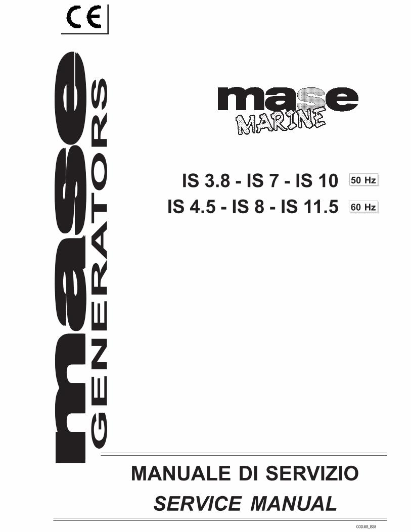
4.1.5.3 Diodi
Caratteristiche: 1A 1000V
Direzione normale 0,850 ΩDirezione inversa Mancanza di continuità
Testing method:
-Remove the relay.-Verify that there is continuity between 86 and 85(Fig. 20).
-Verify that after exciting the coil (apply 12V toterminals 86 and 85) contact 30-87 is CLOSEDandcontact 30-87b is OPEN.
REMEDY: Replace the relay.
4.1.5.3 Diodes
Characteristics: 1A 1000V
Normal Direction 0,850 ΩReverse Direction NO continuity
87
85
3086
87B
Fig. 21

Metodo di controllo:
-Scollegare i cavi del diodo (dissaldare)-Verificare che la resistenza fra le due estremitàrientri nei valori indicati in tabella.
-Verificare che invertendo i puntali del tester nonci sia più continuità.
RIMEDIO: Sostituire il diodo.
4.2 ROTORE
Testing method:
-Disconnect the diode.-Verify that the resistance value between itsterminals is as reported in the above table.
-Invert the tester terminals and verify that there isno continuity.
REMEDY: Replace the diode.
4.2 ROTORE
Fig. 23
–
+
IS 3.8 50 HZ. 41.2 ΩIS 4.5 60 HZ. 41.2 Ω
IS 7 50 HZ. 54.0 ΩIS 8 60 HZ. 54.0 Ω
IS 10 50 HZ. 60.3 ΩIS 11.5 60 HZ. 60.3 Ω
Operations:
-Remove the screws (Fig. 22, Ref.1) and thecover ( fig. 22 rif. 2).
4.2.1Rotor winding
Operazioni:
-Rimuovere il coperchietto (Fig. 22, Rif. 2) dopoaver tolto le viti ( fig. 22 rif. 1).
4.2.1Avvolgimento di rotore
Fig. 22
2
1

Caratteristiche:
Metodo di controllo:
-Scollegare un cavo del portaspazzole emisurare la resistenza fra «+» e «–».
-Verificare che la resistenza fra le due estremitàrientri nei valori indicati (Fig. 23).
RIMEDIO: Sostituire il rotore.
IMPORTANTELa mancanza di tensione in uscita può esserecausata eccezionalmente dalla mancanza oinsufficienza di magnetismo residuo del rotore.
Characteristics:
Testing Method:
-Disconnect the brush holder wire and measurethe resistance value between «+» and «–».
-Verify that the resistance value between the wireterminals is as reported in the above table(Fig. 23).
REMEDY: Replace the rotor.
WARNINGIf there is still no power output, it could depend,very rarely, on a lack of residual magnetism onthe rotor.
Fig. 24
2
1
4
3
5
4.3 ALTERNATORDISMOUNTING/MOUNTING
4.3 SMONTAGGIO/ MONTAGGIOALTERNATORE
Preliminary operations
-Disconnect the water hoses from the heatexchanger (Fig. 24, Ref. 1).
-Remove the plastic cover (Fig. 24, Ref. 4).-Remove the screws (Fig. 24, Ref. 3) and the heatexchanger (Fig. 24, Ref. 2).
-Disconnect the cables from the terminal board(Fig. 24, Ref. 2).
-Disconnect the alternator cables (Fig. 24, Ref. 5).
Operazioni preliminari
-Scollegare dallo scambiatore i tubi acqua(Fig. 24, Rif. 1)
-Togliere il coperchio in plastica (Fig. 24, Rif. 4).-Togliere le viti di fissaggio (Fig. 24, Rif. 3)rimuovere lo scambiatore (Fig. 24, Rif. 2)
-Scollegare i cavi dell’alternatore(Fig. 24, Rif. 5).

Fig. 25
41
2
3
Fig. 26
3
4
2
1
Sostituzione del rotore
-Eseguire le operazioni descritte in precedenza.-Togliere le viti (Fig. 26, Rif. 1) e rimuovere ilcoperchio alternatore lato motore(Fig. 26, Rif. 2)
-Togliere le viti (Fig. 26, Rif. 3) e rimuovere ilrotore (Fig. 26, Rif. 4).
Removal of the rotor
-Carry out the preliminary operations.-Remove the screws (Fig. 26, Ref. 1) and thealternator cover (Fig. 26, Ref. 2) on the engineside.
-Remove the screws (Fig. 26, Ref. 3) and the rotor(Fig. 26, Ref. 4).
Removal of the stator
-Carry out the preliminary operations.-Remove the brush holder (Fig. 25, Ref. 4).-Remove the nuts (Fig. 25, Ref. 1) and the cover(Fig. 25, Ref. 2) on the bearing side.
-Remove the stator (Fig. 25, Ref. 3).
Sostituzione dello statore
-Eseguire le operazioni descritte in precedenza.-Smontare il portaspazzole (Fig. 25, Rif. 4).-Svitare i dadi (Fig. 25, Rif. 1) e togliere ilcoperchio alternatore lato cuscinetto(Fig. 25, Rif. 2).
-Estrarre lo statore (Fig. 25, Rif. 3).

MOUNTING
Remount the alternator following the operationsdescribed in the previous paragraph, inverting theorder of their execution.
WARNINGUse a dynamometric spanner, taking into accountthe following tightening torque.- Cover tie rods 1.5 Kgm.
4.4 CONTROL PANEL
4.4.1Printed circuit
Control panel (Fig. 27).
MONTAGGIO
Eseguire le varie operazioni di rimontaggio nell’or-dine inverso riportato a quanto descritto in prece-denza.
IMPORTANTEUtilizzare una chiave dinamometrica rispettan-do le seguenti coppie di serraggio.- Tiranti coperchi 1,5 kgm.
4.4 CRUSCOTTO COMANDI
4.4.1Circuito stampato
Pannello comandi (Fig. 27).
Fig. 27
1
Metodo di controllo:
-Verificare tutte le funzioni del generatore(avviamento, arresto, dispositivi di sicurezza).
-Verificare le possibili cause di mancatofunzionamento (batteria, motorino avviamento,pressostato, termostato, interruttore termico).
RIMEDIO: Sostituire il circuito stampato (Fig.27).
Testing method:
-Verify all the generator’s functions (start, stop,safety devices).
-Verify all the possible causes of not proper running(battery, starter, oil pressure switch, watertemperature switch, alternator thermostat).
REMEDY: Replace the printed circuit (Fig. 27).

4.4.2Remote control panel4.4.2Comando distanza
Metodo di controllo:
-Verificare tutte le funzioni del comando adistanza.
-Scollegare il connettore (Fig. 28, Rif. 1) everificare le stesse funzioni dal cruscottocomandi.
RIMEDIO: Sostituire il comando a distanza.
4.5 ALTRI PARTICOLARI
4.5.1Scambiatore di calore (acqua/aria)
4.5.1.1 Fascio tubiero
Caratteristiche:
Libero da incrostazioni
Fig. 29
2
1
3
Testing method:
-Verify all the functions of the remote control panel.-Disconnect the connector (Fig. 28, Ref. 1) andverify the same functions with the control panel.
REMEDY: Replace the remote control panel.
4.5 OTHER COMPONENTS
4.5.1 Heat exchanger (Water/air)
4.5.1.1 Tube nest
Caracteristics:
Fouling free
Fig. 28
1

Metodo di controllo:
-Distaccare i tubi acqua (Fig. 29, Rif. 1)-Togliere le viti (Fig. 29, Rif. 3) e rimuovere loscambiatore (Fig. 29, Rif. 2)
-Verificare visivamente
RIMEDIO: Immergere il fascio tubiero in unasoluzione di acqua (90%) e acidoclorido (10%) alla temperatura di 50°C.Sostituire se necessario.
4.5.1.2 Anodi di Zinco
Caratteristiche:
- Consumo regolare
Testing method:
- Disconnect the water hoses (Fig. 29, Ref. 1)- Remove the screws (Fig. 29, Ref. 3) and the heatexchanger (Fig. 29, Ref. 2)
- Verify visually
REMEDY: Wash the tube nest immersing it in awater (90%) and hydrochloric acid(10%) at 50°C temperature.Replace it necessary.
4.5.1.2 Zinc anodes
Characteristics:
- Regular consumption
Fig. 30
1
Metodo di controllo:
-Controllare visivamente-Svitare e togliere i tappi completi(Fig. 30, Rif. 1).
RIMEDIO: Sostituire i tappi completi.
4.5.2Controlli su altri particolari
4.6.2.1 Elettromagnete - Stop IS 3.8 - 4.5
Bobina di ritenuta 17.7 Ω
Bobina di attrazione 0.4 Ω
Testing method:
-Check visually-Unscrew and remove the complete plugs(Fig. 30, Ref. 1).
REMEDY: Replace the complete plugs.
4.5.2Other components
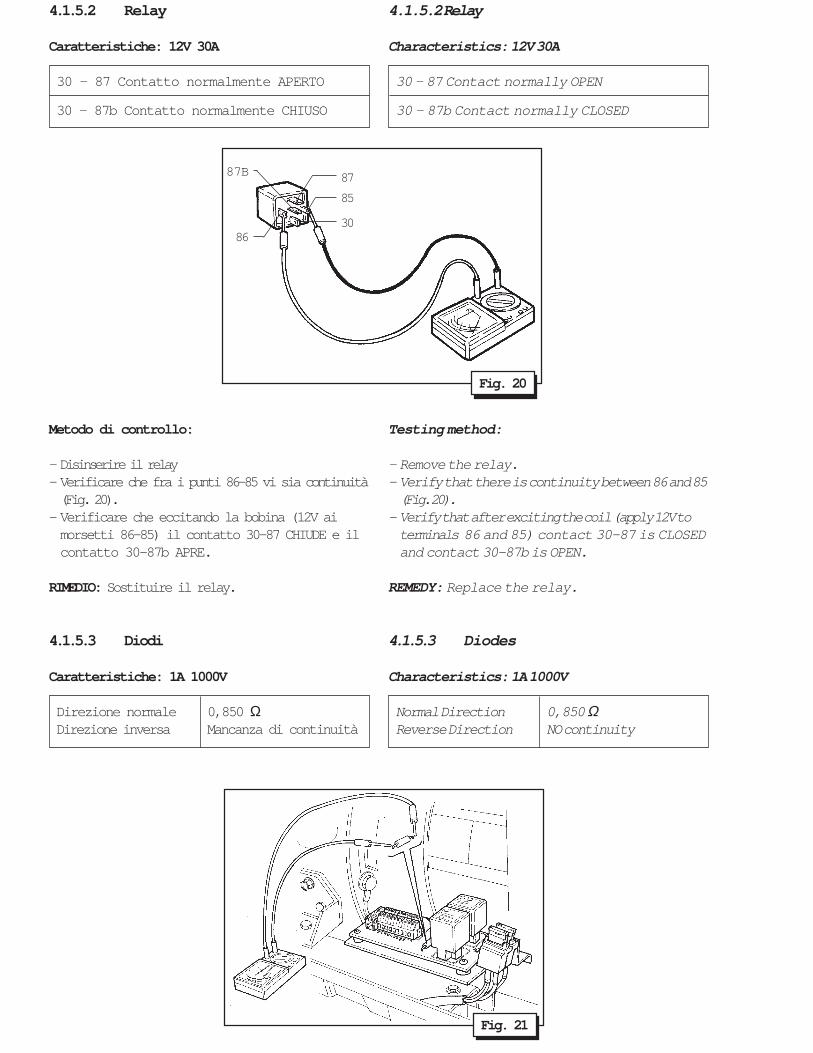
4.6.2.1 Fuel - Solenoid IS 3.8-4.5
Hold coil 17.7 Ω
Pull coil 0.4 Ω
Fig. 31
Metodo di controllo:
- Scollegare i cavi dai due terminali fast-on(Fig. 31)
-Verificare la resistenza dell’avvolgimento diritenuta fra il fast-on più piccolo e massa
-Verificare la reistenza dell’avvolgimento diattrazione fra il fast-on più grande e massa.
RIMEDIO: Sostituire l’elettromagnete.
N.B.In alternativa è possibile eseguire la seguenteverifica pratica utilizzando una batteria da 12 V.
-Con il positivo della batteria al fast-on grandeed il negativo a massa l’elettromagnete deveandare in trazione.
-Con il positivo della batteria al fast-on pirccoloed il negativo a massa l’elettromagnete, dopoessere stato posizionato manualmente, deveessere rilasciato.
4.5.3Elettrovalvola(IS 7/8 - IS 10/11.5)
Caratteristiche:
12V normalmente chiusaBobina 18.3 Ω
Testin method:
-Disconnect the two wires from the fast-on terminals(Fig. 31)
-Verify that the resistance value of the hold coilmeasured between the smaller fast-on and groundis as reported in the table above.
-Verify that the resistance value of the pull coilmeasured between the bigger fast-on and grondis as reported in the table above.
REMEDY: Replace the fueld solenoid.
N.B.As an alternative it’s possible to test the solenoidwith a 12V battery.
-Connect battery (+) to the bigger fast-on and thebattery (–) to ground. The fueld solenoid mustretract.
-Connect the battery (+) to the smaller fast-on andthe battery (–) to ground. The fuel solenoidmanually pressed must hold.
4.5.3Stop solenoid(IS 7/8 - IS 10/11.5)
Characteristics:
12V normally closedCoil 18.3 Ω
IS 3.8/4.5

Metodo di controllo:
-Scollegare il fast-on (Fig. 32, Rif. 1)
-Verificare che la resistenza dell’avvolgimentofra il fast-on e massa abbia il valore indicato.
RIMEDIO: Sostituire l’elettrovalvola.
4.5.4Regolazione dei giri
Poichè gli alternatori MASE sono del tipo a duepoli vale la corrispondenza 1 Hz.==>60 giri/min.(3.000 giri/min.==>50 Hz, 3600 giri/min==>60 Hz).
Caratteristiche:
IS 3.8/7/10 50 Hz-A vuoto 52/52.5 Hz.-A pieno carico 50/51 Hz.
IS 4.5/8/11.5 60 Hz.-A vuoto 62/62.5 Hz.-A pieno carico 60/61 Hz.
Fig. 33
IS 3.8/4.5
2
1
Fig. 32
1
IS 7/8-10/11,5
Testing method:
-Disconnect the fast-on terminal (Fig. 32, Ref. 1)
-Verify that the resistance value between thefast-on terminal and ground is as reported above.
REMEDY: Replace the solenoid.
4.5.4Engime speed adjostement
Since the alternator is a two pole type, 1 Hz.corresponds to 60 R.P.M. (3000 R.P.M.==>50 Hz.3600 R.P.M.==> 60 Hz.).
Characteristics:
IS 3.8/7/1050 hz.-At no loa 52/52.5 Hz.-At full load 50/51 Hz.
IS 4.5/8/11.5 60 Hz.-At no load 62/62.5 Hz.-At full load 60/61 Hz.

Fig. 33a
Regolazione - Stop (Fig. 33a)
-Spostare tutto il sistema di Stop a finecorsa(IN TIRO) dell’elettromagnete (Fig. 33a, Rif. 1)
-Togliere il tappo (Fig. 33a, Rif. 2); verificare chela cremagliera della pompa di iniezione sia tuttaaperta
-Regolare il sistema di stop registrando l'astatirante tramite i dadi (Fig. 33a, Rif. 3).
Adjusting the stop (Fig. 33a)
-Move the entire stop system to the limit positionof the elctromagnet (Fig. 33a, Ref. 1) (pull).
-Remove the cap (Fig. 33a, Ref 2), and checkthat the injection pump rack is fully extended
-Adjust the stop-system setting the pulling rodtrough the nuts (Fig. 33a, Ref. 3).
Regolazione finecorsa Stop (Fig. 33b)
-Allentare le viti (Fig. 33b, Rif. 1).-Ruotare la staffa (Fig. 33b, Rif. 2) fino a rag-giungere il punto massimo, tornare indietro di 2-3 mm, accostare la staffa (Fig. 33b, Rif. 3).-Serrare le viti (Fig. 33b, Rif. 1).
Fig. 33b
2
3
13
2
1
3
Adjusting RPM (Fig. 33) IS 3.8/4.5-Back off the screw (Fig. 33, Ref. 1)-Turn the plate (Fig. 33, Ref. 2) until the requiredrpm is obtained
-Tighten the screw (Fig. 33, Ref. 1).
Regolazione dei giri (Fig. 33) IS 3.8/4.5-Allentare la vite (Fig. 33, Rif. 1)-Ruotare la piastra (Fig. 33, Rif. 2) fino adottenere il numero di gira desiderato.
-Stringere la vite (Fig. 33, Rif. 1).
Stop setting (Fig. 33b)
-Loose off the screws (Fig. 33b, Ref. 1).- Turn the bracket (Fig. 33b, Ref. 2) until themaximum position is reached, then turn back 2-3mm and move the bracket (Fig. 33b, Ref. 3) closer.-Tighten the screws (Fig. 33b, Ref. 1).

Testing method:
-Verify the frequency at the power terminals usinga suitable instrument (vibrating-reed or digitalfrequency-meter).
In order to have correct readings of voltage andamperage values use instruments with trueeffective value (R.M.S.) only.
N.B.Since the voltage is proportional to the frequency,if there is a voltage fluctuaction check the R.P.M.
IMPORTANTSince the engine R.P.M. is calibrated and blockedduring testing, it is advisable not to set it again.The given indications refer to emergency repairand they should be followed by a check-up of theengine. For your information, looking for causesof low efficiency of the engine, it is advisable tocheck the conditions of air/fuel filters andinjectors.
Regolazione dei giri (Fig. 34) IS 7/8-IS 10/11,5
-Allentare il dado (Fig. 34, Rif. 1)-Agire sul perno filettato (Fig. 34, Rif. 2) sino alraggiungimento del numero di giri desiderato
-Bloccare il dado (Fig. 34, Rif. 1)
Adjusting RPM (Fig. 34) IS 7/8-IS 10/11,5
-Back off the nut (Fig. 34, Ref 1)-Adjust the threaded rod (Fig. 34, Ref. 2) until therequired rpm is obtained
-Tighten the nut (Fig. 34, Ref. 1).
Metodo di controllo:
-Verificare la frequenza dell’uscita dei morsettidi potenza con uno strumento idoneo(Frequenziometro a lamelle o digitale).
Per una lettura corretta dei valori di tensione eamperaggio utilizzare solo strumenti a verovalore efficace (R.M.S.).
N.B.Poichè la tensione generata dal gruppo è pro-porzionale alla frequenza, verificare il numerodi giri del motore quale possibile causa dianomalie di tensione.
IMPORTANTEPoichè la taratura del numero di giri del motoreviene eseguita e quindi bloccata in sede dicollaudo si sconsiglia in generale di interveniresulla stessa. Le indicazioni date qui sono rife-rite ad interventi di prima necessità a cui dovràfar seguito un controllo del motore. A titoloindicativo fra le possibili cause di basso rendi-mento del motore si consiglia di verificare l’even-tualità di filtro aria o filtro nafta intasati, iniettoredifettoso od otturato.
Fig. 34
IS 7/8 - IS 10/11.5
1
2

4.5.5Termostato acqua
Caratteristiche:
Contatto normalmente aperto.Contatto chiuso T > 65°C (IS 3.8/4.5);
T > 106°C (IS 7/8 - IS 10/11.5)
4.5.5Water temperature switch
Characteristics:
The contact is normally open.The contact is closed at T > 65°C (IS 3.8/4.5);
T > 106°C (IS 7/8 - IS 10/11.5)
Fig. 35
IS 3.8/4.5
Fig. 36
IS 7/8 - IS 10/11.5
Metodo di controllo:
-Verificare che non ci sia continuità fra il positivoe massa (Fig. 35/36).
-Immergere il termostato in acqua bollente everificare che chiuda il contatto.
RIMEDIO: Sostituire il termostato.
4.5.6Pressostato olio
Caratteristiche:
Contatto normalmente apertoContatto chiuso P < 0.2 Kg
Testing method:
-Verify that there is no continuity between (+) andground (Fig. 35/36).
-Put the termostat in water and check if the contactcloses.
REMEDY: Replace the thermostat.
4.5.6Oil pressure switch
Characteristics:
The contact is normally openThe contact is closed at P < 0.2 Kg
Fig. 37
IS 3.8/4.5
Fig. 37a
IS 7/8 - IS 10/11.5

Metodo di controllo:
-Verificare che a motore spento ci sia continuitàfra il positivo e massa (Fig. 37-37a).
-Verificare che accendendo il motore con l’olio alivello si interrompa la continuità fra il positivo emassa.
RIMEDIO: Sostituire il pressostato.
IMPORTANTEIl pressostato olio non da un’indicazione esattadel livello dell’olio. E’ indispensabile quindi uncontrollo periodico (8 H) per evitare danni almotore.
4.5.7Motorino avviamento
Caratteristiche: 12V.
Testing method:
- Check if there is continuity between (+) andground when the engine is not running (Fig. 37-37a).
- Check if there is no continuity between (+) andground when the engine is running and the oil isat the right level.
REMEDY: Replace the pressure switch.
WARNINGThe pressure switch doesn’t provide exactindication about the oil level.A periodic check (8H) of the oil level is indispensable to prevent theengine from blowing up.
4.5.7Starter
Characteristics: 12V.
Fig. 38
Metodo di controllo:
-Scollegare i cavi-Utilizzare una batteria 12V collegando il (+)della batteria con il morsetto a vite ed il (-) amassa (carcassa del motorino) (Fig. 38).-Verificare che il motorino giri facendo un pontefra il morsetto a vite (+ motorino avviamento)ed il fast-on adiacente (Fig. 38, Rif. 1).
RIMEDIO: Sostituire il motorino d’avviamento.
Testing method:
-Disconnect the wires-Connect 12V battery (+) pole with the screwclamp and (-) pole to the body of the starter(Fig. 38).
-Connect the screw clamp and the adjacentfast-on and verify if the starter is running well(Fig. 38, Ref. 1).
REMEDY: Replace the starter.
1

5.0 Tabella guasti 5.0 Trouble shooting
PART
E E SI
FERM
AN
ON
PAR
TE
FUM
O N
ERO
vedi par.4.4
vedi par. 4.5.2.1/4.5.3
vedi manualeinstallazionevedi par. 4.5.7
vedi manualeinstallazionevedi par. 4.1.5.1
vedi par. 4.1.5.2
vedi par. 1.0
vedi par. 4.5.5/4.5.6
vedi par. 1.0
vedi manuale motore
vedi manuale motore
vedi manuale motore
vedi manuale motore
vedi manuale motore
vedi manuale motore
vedi manuale motore
vedi manuale motore
PULSANTI AVVIAMENTODIFETTOSIELETTROVALVOLA OELETTROMAGNETE DIFETTOSIBATTERIA DIFETTOSA /SEZIONE CAVI INSUFFICIENTEMOTORINO D'AVVIAMENTODIFETTOSOCIRCUITO /FILTRO COMBUSTIBILEFUSIBILE CIRCUITO 12V
RELAY AVV. / EV.
ECCESSIVA QUANTITÀOLIO CARTERINTERVENTO PROTEZIONI
SOVRACCARICO
LEVERAGGI REGOLATE
GUIDA VALVOLEUSURATA
VALVOLE BLOCCATE
CILINDRO E SEGMENTIUSURATIINIETTORE DIFETTOSO
POMPA INIEZIONE
POMPA ALIMENTAZIONE
SPURGO NAFTA
••
•••••
•
•
••
••
•
•
• ••
•••
•••• •
••
RIMEDIO
ANOMALIE
CAUSAPROBABILE
see par. 4.4
see par. 4.5.2.1/4.5.3
see installationmanualsee par. 4.5.7
see installationmanual
see par. 4.1.5.1
see par. 4.1.5.2
see par. 1.0
see par. 4.5.5/4.5.6
see par. 1.0
see engine manual
see engine manual
see engine manual
see engine manual
see engine manual
see engine manual
see engine manual
see engine manual
••
•••••
•
•
••
••
•
•
• ••
•••
•••• •
••
SOLUTIONPROBABLEREASON
COMPLAINT
CONNESSIONI INTERROTTE
REGOLATORE DI TENSIONE
SPAZZOLE ROT.
AVVOLGIMENTO DI ROTOREDANNEGGIATOAVVOLGIMENTO DI ECCITA-ZIONE DANNEGGIATOAVVOLGIMENTO DI POTENZADANNEGGIATOAVVOLGIMENTO DI CARICABATTERIA DANNEGGIATOFUSIBILE
REG. CARICA BATTERIA
DANNEGGIATO
CAUSAPROBABILE
• •• •• •• •• •• •
•••
ANOMALIE
PROBABLEREASON
• •• •• •• •• •• •
•••
COMPLAINT
RIMEDIO SOLUTION
VOLT
AGE
AT T
HE B
ATTE
RYCH
ARGE
R CI
RCUI
T
FUMO
BIA
NCO
REGIM
E INS
TABIL
E
vedi par. 4.0
vedi par. 2.0
vedi par. 4.2
vedi par. 4.2.1
vedi par. 4.1.1
vedi par. 4.1.2
vedi par. 4.1.3
vedi par. 4.1.3.1
vedi par. 4.1.3
DEFECTIVE STARTING BUTTONS
DEFECTIVE FUEL SOLENOID
DEFECTIVE BATTERY /BATTERY CABLE SECTION
DEFECTIVE STARTING MOTOR
PIPING FUEL FILTER CHOKED
12V CIRCUIT FUSE
AVV. / EV. RELAY
TOO MUCH OIL IN CRANKASE
SAFETY DEVICE INTERVENTION
OVERLOAD
DEFECTIVE GOVERNORLINKAGEWORN VALVE GUIDES
BLOCKED VALVES
WORN CYLINDER ANDPISTON RINGS
DEFECTIVE INJECTOR
DEFECTIVE INJECTOR PUMP
DEFECTIVE FEEDING PUMP
DIESEL DUMP VALVE
UNST
ABLE
RUNN
ING
DOES
NOT
STA
RT
WHI
TE S
MOKE
BLAC
K SM
OKE
STAR
T AN
D ST
OPS
DEFECTIVE CONNECTIONS
VOLTAGE REGULATOR
BRUSHES
DEFECTIVE ROTOR WINDING
DEFECTIVEEXCITATION WINDING
DEFECTIVE POWER WINDING
DEFECTIVE BATTERY CHARGERWINDINGFUSE INTERVENTION
BATTERY CHARGER GOVERNOR
see par. 4.0
see par. 2.0
see par. 4.2
see par. 4.2.1
see par. 4.1.1
see par. 4.1.2
see par. 4.1.3
see par. 4.1.3.1
see par. 4.1.3
NO V
OLTA
GE A
T TH
EA.
C. O
UTPU
T
VOLT
AGE
DIFF
EREN
TFR
OM R
ATED
OUT
PUT
MAN
CA D
IVER
SADA
220
V N
OM
INAL
E
MA
NC
A
TE
NS
ION
E22
0 V
MA
NC
A T
EN
SIO
NE
12 V

6.0 Schema elettrico macchina 6.0 Machine wiring diagram
RIF. DESCRIZIONE DESCRIPTION
1 Rotore Rotor2 Statore Stator3 A.V.R. A.V.R.4 Morsettiera di potenza Power terminal board5 Scheda relay Printed circuit6 Fusibile 1 A Fuse 1 A7 Morsettiera circuito relay Relay circuit terminal board8 Morsettiera pannello comandi Control panel terminal board9 Fusibile 30 A Fuse 30 A10 Regolatore carica batteria Battery charger regulator11 Pressostato olio Oil pressure switch12 Motorino avviamento Starter motor13 Batteria Battery14 Termostato testata motore Overhead engine thermostat15 Elettrovalvola stop Fuel solenoid15 * Elettromagnete stop Stop solenoid16 Termostato alternatore Alternator thermostat
P 2P 1
F 1
F 2

6.1 SCHEMA ELETTRICO DICOLLEGAMENTO PANNELLO
6.1 WIRING DIAGRAM OF CONTROLPANEL CONNECTION
RIF. DESCRIZIONE DESCRIPTION
1 Morsetto 110 V Terminal board 110 V2 Connettore scheda relay Relay circuit connector3 Connettore pannello a distanza Remote control panel connector4 Calza di massa Earth braid5 Morsettiera pannello comandi Control panel terminal board6 Morsettiera circuito relay Relay circuit terminal board7 Fusibile 1 A Fuse 1 A8 Contaore Hourmeter
GREENYELLOWBLACKGRAYBLUE
ORANGERED
EARTHBRAID
CAVO / CABLE AMORSETTIERA
TERMINAL BOARDCOLORE COLOUR
CAVO / CABLE BMORSETTIERA
TERMINAL BOARD COLORE COLOUR
12
NEROROSSO
BLACKRED
3456789
8x0,35 mm2
2x0,5 mm2
PANNELLO A DISTANZAREMOTE CONTROL PANEL
SCATOLA DERIVAZIONEBRANCK BOX
1
2
3
4
8
56
7
4
PANNELLO COMANDICONTROL PANEL
VERDEGIALLONEROGRIGIOBLUARANCIOROSSO
CALZAMETALLICA