Embed Size (px)
Citation preview

Disclosure to Promote the Right To Information
Whereas the Parliament of India has set out to provide a practical regime of right to information for citizens to secure access to information under the control of public authorities, in order to promote transparency and accountability in the working of every public authority, and whereas the attached publication of the Bureau of Indian Standards is of particular interest to the public, particularly disadvantaged communities and those engaged in the pursuit of education and knowledge, the attached public safety standard is made available to promote the timely dissemination of this information in an accurate manner to the public.
इंटरनेट मानक
“!ान $ एक न' भारत का +नम-ण”Satyanarayan Gangaram Pitroda
“Invent a New India Using Knowledge”
“प0रा1 को छोड न' 5 तरफ”Jawaharlal Nehru
“Step Out From the Old to the New”
“जान1 का अ+धकार, जी1 का अ+धकार”Mazdoor Kisan Shakti Sangathan
“The Right to Information, The Right to Live”
“!ान एक ऐसा खजाना > जो कभी च0राया नहB जा सकता है”Bhartṛhari—Nītiśatakam
“Knowledge is such a treasure which cannot be stolen”
“Invent a New India Using Knowledge”
है”ह”ह
IS 3842-5 (1968): Application guide for electrical relaysfor ac systems, Part 5: Distance protection relays [ETD 35:Power Systems Relays]


IS:3su(Partv)-1968
Indian Standard APPLICATION GUIDE FOR ELECTRICAL
RELAYS FOR BC SYSTEMS
PART V DISTANCE PROTECTION RELAYS
( Fifth Reprint OCTOBER 1993 )
UDC 621.316.925.4s
@ Copyright 1969
BUREAU OF INDIAN STANDARD S MANAK BIUVAN, 9 BAHADUR SHAH ZAFAR MARC
NEW DELHI 110002
Gt 9 December 1969
IS : 3842 ( Part V ) - 1968
Indian Standard APPLICATION GUIDE FOR ELECTRICAL
RELAYS FOR ac SYSTEMS
PART V DISTANCE PROTECTION RELAYS
Relays Sectiollal C:ommittec, BTDC 35
SHRI G. K. THAKUR (Afternate to Shri K. M. Chinnappa )
SHRXV. BALASUUR~M~NIAN Hindustan Brown Boveri Lid, Bomba> SHRI S. V. DIXIT ( Alternate )
CHIEF ELXCTRICALL ENOIS~~R Hailway Board ( 1Iinistry of linilxxys ) (CENTRAL RAILWAY )
CHIEF ELE~TRICAI, E~~I- NEER ( RAILWAY ELECTRI- FIOATION) ( A/lenU?le)
SHRI A. DATTA Jyoti Limited, Barode SEBI B. L. SINHVAL ( Afrernafe )
&RI 5. L. DESAI Directorate- General of Posts C Telegraphs ( Ministry of Transport & Communications)
SH~I M. S. KRIS~NASWAMY Mysore State Electricity Board, Bangaloro SH~I B. H. MEAT&~ The Bombay Electric Supply and Transport
Undertaking, Bombay SH~I A. D. LIMAYE ( Alternare)
8~arB.K. MUXHERJEE National Test House, Calcutta Saar S. MUTHURAMAN ASEA Electric India Pvt Ltd. Bontbuy
SHBI 5. T. PATEL ( Affernore ) Saar ft. PAD~ANAB~AN The Sata Iron and Steel Co Ltd, Jamshedpur
SHRI B. R. KAXATH ( Alternate ) SRRI S. 0. PARANOE Directorate General of Supplies & Disposals
( Inspection Wing) ( Ministry of Supply, Technical Development & Materials Planning )
SHBI M. 9. RAJAOOPALAN The English Electric Co of India Ltd. Madras SEBI N. NATE ( Affernore )
OHRI A. RAJARAO Heevy Eleotricals ( India ) Ltd. Bhopel P~OF H. N. RAHACHANDRA RAO Indian Institute of Science, Bangelore
( Conrinued on page 2 )
BUREAU OF INDIAN STANDARDS MANAK BHAVAN, 9 BAHADUR SHAH ZAFAR MARC3
NEW DELHI 110002
IS : 3842 ( Part V ) - 1968
( Cotrfirrrreci from puge I )
Memhs Representing
SIIHI S. 1‘. R_~~DAK Jnternational General Electric CO of India Private Ltd, Bombay
QHRI P. LLI~NOASWAMP Hindustan Steel Ltd, Ranchi SJIRI P. K. SEN Punjab State Electricity Board, Patiala Sum M. 11. SHET~INA Siemens India Ltd, Bombay
Smtr M. C. AOAXWALA ( Alteruate ) SlIRI c. s. SRI~ENIVASAN Central Water & Power Commission (Power
Wing ) Sriax 1,. C. JAIN ( Alternate )
SHRI Y. Y. VEXI<.~TUW~~AN, Director General BIS, ‘( Ex-officio Member ) Director ( Elec 113-h )
Secretary
SHRI R. C. BAJPAI
Deputy JXrertor ( Elec tech ), BIS
l’allel for Applicatioll Guide for Electrical Relays, ETDC 35 : P2
Convener PIIOF H. N. RAXACHANDRA RAO Indian Institute of Science, Bangalore
Members
SHRI N. NATIL The English Eleotric Co of Indie Ltd, Madras SHRI V. RADHAKRISRNAN Heavy Electricals ( Indis ) Ltd;Bhopel SARI P. K. SEN Punjab State Electricity Board, Patiale SRRI M. M. SHETRNA Siemens India Ltd, Bombay SHRI C. S. SREENIVABAN Centrel Water & Power Commission ( Poiver
Wing ) SERI G. K. THAKUR Tats Hydro-Electric Power Supply Co Ltd,
Bombqy
0.
1.
2.
3.
4.
5.
6.
7.
8.
9.
10.
Il.
12.
13.
14.
15.
16.
17.
IS : 3842 ( Part V ) - 1968
CONTENTS
PAGE
FOREWORD ............... 4
SCOPE ............... 6
TERMIIWLO~Y . . . . . . . . . . . . 6
CLASSIFICATION ACCORDING TO POLAR CHARACTERISTICS . . . 6
POLARIZING SUPPLIES . . . . . . . . . . . . 10
CLAWPICATION ACCORDING TO TYPE OF COMPARATOR . . . 11
PERFORMANCE OF DISTANCE RELAYS . . . . . . 13
DISTANCE SCHEMES . . . . . . . . . . . . 16
STARTER RELAYS FOR DISTANCE PROTECTION . . . 16
IMPEDANCES SEEN BY DISTANCE RELAYS ...... 20
APPLICATION OF DISTANCE RELAYS ...... 21
MISCELLANEOUS PROBLEMS ASSOCXATED WITH DISTANCE RELAYING . . . . . , . . . . . . . . . 23
EFFECT OF FUSE FAILWRB . . . . . . . . . 31
DISTANCE RELAY& IN CONJUNCTION WITH AUTO-RECLOS- INO AND CARRIER. CHANNEL . . . . . . . . . 33
APPLICATION OF DISTANCE RELAYS TO TEED LINES . . . 35
APPLICATION OF DISTANCE RELAYS FOR SINOLE-POLB AND THREE-POLE AUTO-RECLOSINO . . . . . . . . . 36
INSTRUMENT TRANSFORMER CONNEOTION~ . . . . . . 37
A TYPICAL EXAMPLE OF DISTANOE RELAY APPLmATION . . . 37

IS : 3842 ( Part V) - 1968
Indian Standard
APPLICATION GUIDE FOR ELECTRICAL RELAYS FOR ac SYSTEMS
PART V DISTANCE PROTECTION RELAYS
0. FOREWORD
0.1 This Indian Standard ( Part V ) was adopted by the Indian Stand- ards Institution on 10 December 1968, after the draft finalized by the Relays Sectional Committee had been approved by the Electrotechnical Division Council.
0.2 Modern power systems are designed to provide uninterrupted electrical supply, yet the possibility of failure cannot be ruled out. The protective relays stand watch and in the event of failures, short circuits or abnormal operating conditions help de-energize the unhealthy section of the power system and restrain interference with the remain- der of it and thus limit damage to equipment and ensure safety of personnel. They are also used to indicate the type and location >ffailure so as to assess the effectiveness of the protective schemes.
0.3 The features which the protective relays should possess are:
4
b)
C>
4
e)
Reliability, that is, to ensure correct action even after long periods of inactivity and also to offer repeated operations under severe conditions; Selectivity, that is, to ensure that only the unhealthy part of the system is disconnected; Sensitivity, that is, detection of short-circuit or abnormal operat- ing conditions; Speed to prevent or minimize damage and risk of instability of rotating plant; and Stability, that is, the ability to-operate only under those condi- tions that call for its operation and to remain either passive or biased against operation under all other conditions.
0.4 A distance relay compares the local current with the local voltage as an economical substitute to an ideal protection scheme comparing local current with the remote current. As the operation of such a relay
4

IS : 3842 ( Part V ) - 1968
is made dependent on the ratio U/I = 2 ( 2 being the line impedance or a trigonometric function of it ), it is also a measure of the line length. Hence the name ‘ distance ’ relay.
0.5 Besides being used for protection of feeders and transmission lines, the distance relays are sometimes also used for other applications, such as back-up for generators. However, this guide confines itself to only feeders and transmission lines.
0.6 This guide covers distance protection schemes comprising of electro- mechanical relays only. Distance protection schemes can be made of static and semi-static relays which have not been covered in this guide.
0.7 In the preparation of this guide considerable, assistance has been derived from several published books and from manufacturers’ trade literature. Assistance has also been rendered by State Electricity Boards in collecting actual examples.
0.8 It is emphasized that this guide has been prepared to assist in the application rather than to specify the relay to be used. This guide deals only with the principles of application of distance relays and does not deal with the selection of any particular protective scheme. The actual circuit conditions in all probability may be different from those given here. The examples, even though drawn from actual field applications, should be regarded as mere illustration of one or the other point.
0.9 This guide is one of the series of Indian Standard application guides for electrical relays for ac systems. The other guides in this series are:
IS :
IS :
IS :
IS :
IS :
3638-1966 Application guide for gas-operated relays
3842 ( Part I )-1967 Application guide for electrical relays for ac systems ; Part I Overcurrent relays for feeders and transformers
3842 ( Part II )-1966 Application guide for electrical relays for ac systems : Part II Overcurrent relays for generators and \ motors
3842 ( Part III )-1966 Application guide for electrical relays for ac systems : Part III Phase unbalance relays including negative phase sequence relays
3842 ( Part IV )-1966 Application guide for electrical relays for ac systems : Part IV Thermal relays
IS : 3842 ( Part V ) - 1968
1. SCOPE
1.1 ~Phis guide ( Part V ) deals with the application of distance relays for ac systems, covered by IS : 3231-1965”. and transmission lines.
It applies only to feeders
NOTE - Distance protection schen~es comprising of @atic and semi-static relays are not covered in this guide.
1.2 This guide does not cover the principles of system design and system protection.
2. TER.MINOLOGY
2.1 For the purpose of this guide the definitions given in IS : 1885 ( Part 1X)-1966? and IS : 1885 ( Part X )-1968$ shall apply.
3. CLASSIFICATION ACCORDING TO POLAR CHARACTERISTICS
3.1 General -Distance relays are classified by their polar characteris- tics, number of inputs, and the manner in which the comparison is made. The common types compare two input quantities in either magnitude or phase to obtain characteristics which are either straight lines or circles when plotted on an R--X diagram. The polar characteristics normally obtainable are:
a) Plain impedance;
b) Ohm: 1) Blinder, and 2) Reactance;
c) Mho; d) Offset mho; and e) Modified impedance.
3.1.1 Relay movements and circuits in which two independent quantities are compared are either inherent.ly amplitude or phase com- parators. Any type of characteristic obtainable with one comparator is also obtainable with the other, although the combinations of quantities compared in each case argdifferent.
3.2 Plain Impedance Relay - The plain impedance characteristic shown in Fig. 1 is the sitnplest in use and consists of a circle with centre at the origin. Operation occurs in the shaded area inside the circle. The I_-- -.
*YpeciGcation f0or elect&n1 relays for power syetem protection. +Electrotechnical vocabulary: Part IS Eleatrical relays. ~Eiectrotschnical vocabulary: Part S Electrical power system protection.
6
IS:3842(PartV)-1968
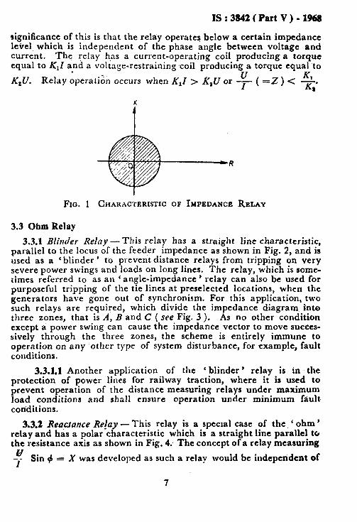
signiticance of this is that the relay operates below a certain impedance leirel which is independent of the phase angle between voltage and current. The relay h,as a current-operating coil producing a torque equal to K,Z and a voltage-restraining coil producing a torque equal to . &U. Relay operati& occurs when K,I > K,U or -+=Z)< 2.
x
FIG. 1 CHARACTERISTIC OF IMPEDANCE RELAY
3.3 Ohm Relay
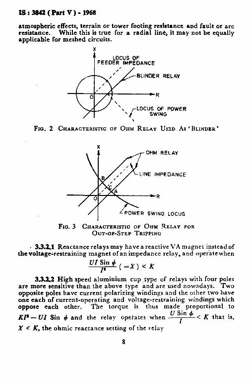
3.3.1 Blinder Relay - This relay has a straight line characteristic, _~ parallel to the locus of the feeder impedance as shown in Fig. 2, and is used as a ‘blinder ’ to prevent distance relays from tripping on very severe power swings and loads on long lines. The relay, which is some- times referred to as an ‘ angle-impedance ’ relay can also be used for purposeful tripping of the tie lines at preselected locations, when the generators have gone out of synchronism. For this application, two such relays are required, which divide the impedance diagram. j:nto three zones, that is A, B and C ( see Fig. 3 ). As no other condition except a power swing can cause the impedance vector to move succcs- sively through the three zones, the scheme is entirely immune to operation on any other type of system disturbance, for example, fault conditions.
3.3.1.1 Another application of the ‘blinder’ relay is in the protection of power lines for railway traction, where it is used to prevent operation of the distance measuring relays under maximum load conditions and shall ensure operation under minimum fault coriditions.
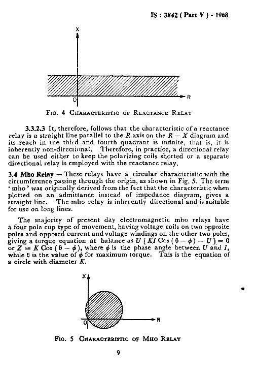
3.3.2 Reatance Re!ay - This relay is a special case of the, ‘ ohm’ relay and has a polar characteristic which is a straight line parallel to the resistance axis as shown in Fig. 4; The concept of a relay measuring
X was developed as such a relay would be independent of
7
IS:3842(PartV)-1968
atmospheric effects, terrain or tower footing resistance and fault or arc resistance. While this is true for a radial line, it may not be equally applicable for meshed circuits.
X
t LOCUS OF
FEEDER IMPEDANCE
BLINDER RELAY
LOCUS OF POWER
\
Fro. 2 CHARACTERISTIC OF OHM RELAY USXD As ‘BLINDER’
LINE IMPEDANCE
POWER SWING LOCUS
Fro. 3 CHARACTERISTIC OF OHM RELAY FOR OUT-OF-STEP TRIPPING
. 3.3.2.1 Reactance relays may have a reactive VA magnet ipstead of the voltage-restraining magnet of an impedance relay, and operate when
*I;;$X)uK
3.3.2.2 High speed aluminium cup ._type of relays with four poles are more sensitive than the above type and are used nowadays. Two opposite poles have current polarizing windings and the other two have one each of current-opergting and voltage-restraining windings which oppose each other. The torque is thus made proportional to
U Sin + KP - WI Sin # and the relay opeiates when ---I < K that is,
X ( K, the ohmic reactance setting of the relay
8
IS : 3842 ( Part V ) - 1968
FIG. 4 CHARACTERISTIC OF REACTANCE RELAY
3.3.2.3 It, therefore, follows that the characteristic of a reactance relay is a straight line parallel to the R axis on the R - X diagram and its reach in the third and fourth quadrant is infinite, that is, it is inherently non-directional. Therefore, in practice, a directional relay can be used either to keep the polarizing coils shorted or a separate directional relay is employed with the reactance relay.
3.4 Mho Relay -These relays have a circular characteristic with the circumference passing through the origin, as shown in Fig. 5. The term c mho ’ was originally derived from the fact that the characteristic when plotted on an admittance instead of impedance diagram, gives a straight line. The mho relay is inherently directional and is suitable for use on long lines.
The majority, of present day electromagnetic mho relays have a four pole cup type of movement, having voltage coils on two opposite poles and opposed current andvoltage windings on the other two poles, giving a torque equation at balance as U [ yZ Cos ( 0 - #) - U 1. = 0 orZ=KCos(O-_),where# is the phase angle between U and I, while 13 is the value ,of 4 for maximum torque. This is the equation of a circle with diameter K.
l
FIG. 5 CHARACTERISTIC OF MHO RELAY
9
IS : 3842 ( Part V ) - 1968
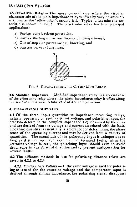
3.5 Offset Mho Relay - The more general case where the circular characteristic of the plain impedance relay is offset by val ying amounts is known as the ‘ ofl&t-rnho ’ characteristic. Typical o&t mho chal ac- teristic is shown in Fig. 6. applications:
The offset mho retay has four pl-incipa\
a) Bus-bar zone back-up protection,
b) Carrier starting in carrier-distance blocking schemes,
c) Out-of-step ( or power swivg ) blocking, and
d) Starters on very long lines.
FK. 6 CHAWKXI:KISTIC OE..OFFSET Mlro RELAY
3.6 Modified Impedance -Modified impedance relay is a special case of the offset mho relay where the plain impedance relay is offset along the R or R and X axis to take care of arc compensation.
4. POLARIZING SUPPLIES
4.1 Of ,the three input quantities to impedance measuring relays, namely, operating current, restraint voltage, and polarizing input, the first two determine the complex impedance (2) measured by the relay and are derived from the voltage and current associated with the fault. The third quantity is essentially a reference for determining the phase sense of the operating current and may be deiived from a variety of quantities. The magnitude of the polarizing input is unimportant so long as it is not zero, for example, for terminal faults, when the restraint voltage is zero, the polarizing input should exist to avoid dead zone in the forward direction and to prevent maloperation for reverse faults.
4.2 The different methods in use for polarizing ‘distance relays are given in 4:2,1 to 4.2.4.
4.2.1 Faulty Phase Voltage - If the same voltage is used for polariz- ing as is used foe the restraint voltage and the comparator input is derived through similar impedance, the polarizing signal disappears
IS : 3842 ( Part V ) - 1968
when the fault impedance is low and thus this method of polarization is not ofpractical USC. It is worth noting, however, that the phase angle relation is always satisfied.
4.2.2 t;uulty Phase Voltage with Memory - If, instead of applying the faulty phase voltage through an impedance similar to the restraint impedance to provide a polarizing input, an alternative impedance consisting of a tuned circuit is used, it is possible to maintain a polariz- ing signal for a short time’after a fault occurs. Thus in the case of a terminal fault the polarizing input will be maintained sufficiently long for operation of the relay to occur. One of the drawbacks of this arrangement is that it is not effective when a line is being energized. The relay’ being initially de-energized, ‘ memory ’ is ineffctive under this condition. This disadvantage may be overcome by using busbar voltage transformers instead of line voltage transformers. However, when line voltage transformers are used, additional relays may be required in case of mho relays to ensure proper operation in case of solid three-phase faults.
The polarizing current does not maintain a constant phase relation to the faulty phase v’oltage. When a fault occurs, the phase angle of the faulty phase voltage alters whereas the memory circuit maintains a current at the original phase angle. This phase angle shift is not excessive and may be tolerated. A further and more seriouscause of phase angle shifts is due to variations in the supply frequency. The resonant circuit always resonates at a fixed frequency whereas the supply frequency may vary between certain limits. To avoid trouble it is essential that ‘ memory’ is restricted to about three cycles at the most. This implies that the relay shall be very fast.
4.2.3 Healthy Phase Voltage - A polarizing voltage may also be ob- tained from one of the healthy phases or,between two phases. The main disadvantage ofthis method is that in the event of a three-phase terminal fault the polarizing voltage disappears. In a number of cases it has been possible to use high-set overcurrent relays which may protect against three-phase terminal fault.
4.2.4 Ft~lry Phase Voltage with a Small Percentage from the Healthy Phases - This condition is similar to that given in 4.2.1, but has an additional 3 to 5 percent of the voltage from one of the leading phases in the voltage polarizing circuit. This voltage is phase shifted to bring it in phase with the faulted phase voltage. This increases the accuracy of distance measurement under low fault-voltage conditions. However, the method has similar limitations as those given in 4.2.3 under three- phase faults.
5. CLASSIFICATION ACCORDING TO TYPE OF COMPARATOR
5.0 As mentioned earlier, comparators are divided into two groups
11
IS : 3842 ( Part V ) - 1968
according to whether a comparison is made of the amplitude of the’two input quantities or of the phase angle between them.
5.1 Amplitude comparators generally employ the following relay movements:
a) Balanced beam, and
b) Induction disc.
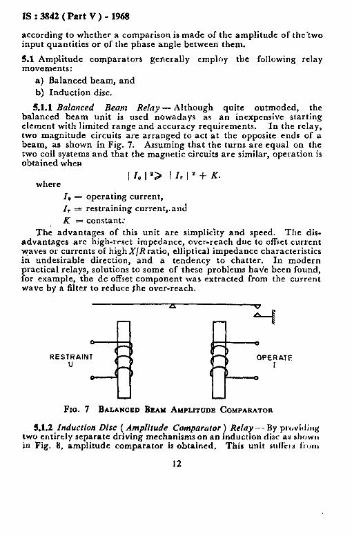
5.1.1 Balanced Beam Relay- Although quite outmoded, the balanced beam unit is used nowadays as an inexpensive starting element with limited range and accuracy requirements. In the relay, two magnitude circuits are arranged to act at the opposite ends of a beam, as shown in Fig. 7. Assuming that the turns are equal on the two coil systems and that the magnetic circuits are similar, operation is obtained when
where I 10 I Q I I, I 2 + K.
I, = operating current,
I, = restraining current,.and
K r: constant:
The advantages of this unit are simplicity and speed. The dis- advantages are high-reset impedance, over-reach due to offset current waves or currents of high X/R ratio, elliptical impedance characteristics in undesirable direction, and a tendency to chatter. In modern practical relays, solutions to some of these problems have been found, for example, the dc offset component was extracted from the current wave by a filter to reduce she over-reach.
RESTRAINT u
OPERATE
Fxo. 7 BALANCED BEAM AMPLITUDE COMPARATOR
5.1.2 Induction Disc ( Amplitude Comparator ) Relay - By proviJiug two entirely separate driving mechanisms on an induction disc as slrowu in Fig. 8, amplitude comparator is obtained, This unit sulfer~ I’I~IUII
12

I!3:3842(PartV)-l!k%
mm of the disadvantages of the beam relay and is much less efficient as it is slow in operation. As such it is not used in any modern distance protection scheme, and is of theoretidal interest only.
.
RESTRAINT U
FIG. 8 INDUCTION DISC AMPLITUDE. COMPARATOR
5.2 Phase angle comparators generally employ the following movements:
a) Induction disc, and b) Induction cup.
5.2.1 Induction Disc ( Phase Angle Comparator ) Relay.- A torque is obtained by the interaction of the fluxes from the two magnetic circuits which act in close proximity on the disc. The unit has a very low sensitivity and suffers from interaction between the two magnetic circuits. It is also difficult to balance and there is a tendency for spurious torques where only one input is applied. It is currently used in directional elements where high performance is not required.
5.2.2 Induction Cup Relay - The induction cup comparator is illustrated in Fig. 9. It is an improved version of the induction disc ( phase angle ) comparator and produces nearly perfect impedance characteristics, has almost equal operate and reset values and is not much affected by offset waves. The comparator may work over a larger range of input quantities and has very little interaction. The forces are proportional to the product of the input quantities. Its construction is compact and robust and it is the most popular high speed electromagnetic unit.
6. PERFORMANCE OF DISTANCE RELAYS
6.1 The ideal polar characteristics so far described are independent of the actual values of current and voltage applied to a distance measuring relay and depend only on the ratio of the input quantities. Practical distance relays depart from the ideal and have characteristics which depend on the actual values of voltage and current. An approximation to the, ideal is obtained only over a limited range of input quantities.
13

IS : 3842 ( Part V ) - 1968
Inside this range the relay will have errors which are acceptable and outside this range it will have excessive errors and may not operate. The operating time of the relay will be variable depending on the indi-
vidual magnitudes of the input quantities, being, for example, long for small inputs near the cut-off impedance and short for large inputs well within the cut-off impedance. The reach accuracy of the relay also depends upon the proportionality between the respective torques and input quantities being maintained. However, depending upon the design of the relay, below a certain value of input voltage, this is no longer true and the relay may not be guaranteed to measure within the specified accuracy. The complete representation of a practical relay has thus to include information on these aspects in addition to the ideal polar characteristics.
A INPUT I A
Fro. 9 INDUCTION CUP PHASE COMPARATOR
6.2 Any c .lt condition in a power system may be represented by a single line a :iagram as shown in Fig. 10. This simple impedance loop has a voltage U applied to it, which may be either the star or delta open circuit voltage of the power system, depending on the type of fault considered. R is identified as the relay location and Ix and un are the current and voltage applied to the relay respectively. The impedances 2,s and ZL are the source and line impedances by virtue of their position with respect to the relay location. Source impedance 2s is a measure of fault MVA at the relaying point and for faults involving earth, is also dependent on the method of system earthing behind the relaying point. Line impedance 2~ is a measure of the impedance of the protected section. The voltage [JR applied to the relay is thus IRZI, for a fault at the reach point, and this may be
14

alternatively expressed ZS /ZL , as follows:
UR = IRzL where
a IS : 3842 ( Part V ) - 1968
in terms of source to line impedance ratio,
. . . . . . . . . . . . . . . . . . . . . . . . . . . . . . . . . . . . (1)
u IR = 2s j- ZL
. . . . . . . . . . . . . . . . . . . . . ...” . . . . . . . . . . . (2)
Thus
u =
( 1-t * 1 . . . . . ,............................... (3)
SOURCE LINE IMPEDANCE
FIG. 10 PERFORMANCE OF A DISTANCE RELAY
6.3 It may be seen from equation 3 of 6.2 that the fault voltage ‘ seen ’ by the relay depends on the source-to-line impedance ratio of a trans- mission system. Relay performance is usually expressed in terms of the minimum ‘ fault voltage ’ that should be seen by the relay, for example, 8 V ( secondary ) across the relay terminals to maintain the accuracy of calibration within & 10 percent. Therefore, the lower the value of the fault voltage across the relay to maintain the accuracy of calibration, the higher will be the 2s /Zh ratio that may be enter- tained, or in other words, the shorter the length of the line that may be protected. The ‘ minimum fault voltage ’ for a fault at the reach point to which the relay will remain accurate varies with the type of relay, that is, impedance, mho or reactance and also with the type of com- parator rmployed.
15
IS : 3842 ( Part V ) - 1968
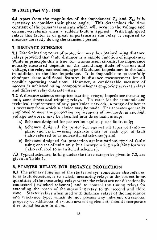
6.4 Apart from the magnitudes of the impedances 2~ and Z,, it is necessary to consider their phase angle. This determines the time constant of the primary transients which will occur in the voltage and current waveforms when a sudden fault is applied. With high speed relays this factor is bf great importance as the relay is required to measure correctly during the transient period.
7. DISTANCE SCHEMES
7.1 Discriminating zones of protection may be obtained using distance relays provided that fault distance is a simple f’unction of impedance. While in principle this is’true for transmission circuits, the impedance actually measured depends on the actual magnitude of current and voltage, the relay connections, type of fault and impedances in the fault in addition to the line impedance. It is impossible to successfully eliminate these additional features in distance measurement for all possible operating conditions. However, a considerable measure of success is achieved using composite schemes employing several relays and different relay characteristics.
7.2 A distance scheme comprises starting relays, impedance measuring unit, zone timers and tripping relays. To cater for the economic and technical requirements of any particular network, a range of schemes is necessary from which a choice may be made. The schemes generally employed to meet the protection requirements of low, medium and high voltage networks, may be classified into three main groups:
a) Schemes designed for protection against phase fault< only;
b) Schemes designed for protection against all types of faults - phase and earth -using separate units for each type of fault ( also referred to as non-switched schemes ); and
c) Schemes designed for protection against various type of faults using one set of units only but incorporating switching features (also referred to as switched schemes ).
7.3 Typical schemes, falling under the three categories given in 7.2, are given in Table 1.
8. STARTER RELAYS FOR DISTANCE PROTECTION
8.1 The primary function of the starter relays, sometimes also referred to as fault detectors, is to switch measuring relays to the correct input quantitie? of the measuring &lays where the relays are not directionally connected ( switched schemes ) and to control the timing relays for extending the reach of the measuring relay to the second and third zone. Starter relays when used with distance relays of the impedance and reactance type, which do not possess any inherent directional property or additional direction measuring clement, should incorporate directional feature in them.
16
IS:3842(Part.V)-1968
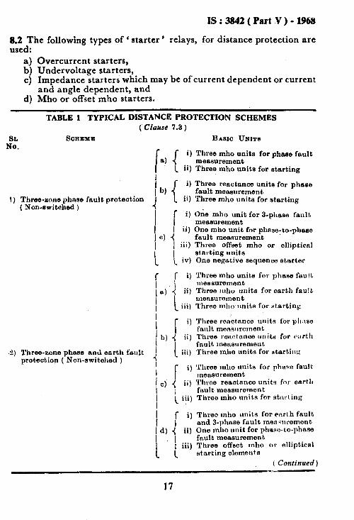
8.2 The following types of ‘ starter ’ relays, for distance protection are used:
a.) Overcurrent starters, b) Undervoltage starters, c) Impedance starters which may be of current dependent or current
and angle dependent, and d) Mho or offset mho starters.
TABLE 1 TYPICAL DISTANCE PROTECTION SCHEMES (‘Clause 7.3 )
E. SCREZ~E BASIC UNITS
r 8) I
i) Three mho units for pheee fault measurement
[ ii) Three mho units for starting
1)
2)
Three-sons phase fault protection ( Non-switched )
b) [ 9 Th ree reactance units for phase fault measurement
1 ii) Three mho units for starting
f i) Ok mho unit for 3-phase fault
measurement I ii) One rnho unit for nhose-to-chase
Three-zone pkyxse nnrl earth fault protection ( Ron-switched )
fault measuremen’t A Three offset mho or elliptical alnrting units One negative sequence starter
Three mho units for phase faulL measurement Three mho units for earth fault measurement Three mhck lmits for starting
Three rsnotnnce urlitn for pll:lse fault mensuroment Three rertctnnce trnitri for ~art.11 fnult measnremeut Three mho units fov atartiilg
Three mho units for phwe fault meaeurement Three reectnnce units for earth fn.ult measurement Throo mho units for stnrling
r i) Three mho unit.s for enrl h fault
I and j-phase fault mens~~rement~ d) ( ii) One mho unit for phase-1 o-phase
I fault measurement ; iii) Three offset mho or elliptical
_ 1 starting elements
( Continued )
17

IS : 3842 ( Part V )-1968
TABLE 1 TYi’ICAL DISTANCE PROTECTION SCHEMES-Confd
I!E. SCEEXE BAEIO UNIW
3) Three-zone phase and earth fault protection (switched )
r 9 . .
B) 4 4 i 1
One mho unit for fault measure- ment Two instantaneous overpurrent startera NOTE -The mho unit is awltched to
the faulted phase by the overcurrent starters.
: i, 1 ii)
b) -+ 1 iii)
t
One reaotance unit for phase and earth fault measurement One mho unit for directionalie- ing reactance unit Three impedance starters
NOTE-The mho and reactance units are switched to the faulted phase(s) by the starters.
r i)
j ii)
‘) 4 iii)
I
t
f i)
1 ii) d) ( iii)
I
I
[ i)
] ii)
0) 3
i iii)
Three impedance units for phase and earth faults Three directional units for phase and earth fnults Three imnedance starters
NOTE _ -The impedance and direc- tional units are switched to measure either phase faults or earth faults by the starters.
One mho unit for phase and earth faults Three impedance starters Overcurrent starters for earth faults
Nora -The mho unit is switched to the faulted phase by the starters.
One mho unit for earth fault and 3-phase fault measurement One mho unit for phase-to-phase fault measurement
L
~~a~t;roffset mho or elliptical
iv) One negative sequence starter
r i) Three impedance units for phase
i’
and earth faults measurement
f) ii) Three directional units for phase
and earth faults 1 iii) Three impedance starters (_ iv) Pour overcurrent starters
8;;3edFollowing combinations of distance and starter re1aJ.s are commonly
a) Directional and overcurrent relays as starters for uie with impedance type of distance relay;
18
IS:32342(PutV)-1968
b) Overcurrent units only for use with mho type of distance relay (sometime und,er-voltage relays are also used specially on resistance earthed systems );
c) Mho starters for any type of distance relay; d) Impedance starters for reactance or impedance type of distance
relay directionalized by a separate mho relay or a directional relay;
e) Current dependent under-impedance star ten for distance relays when heavy loads on medium lines are expected. On heavy loads the reach of the starting relay reduces and at low currents the reach increases; and
f) Current and angle dependent under-impedance starters for distance relays where on heavy loads and long lines the reach, even at high current, is to be maintained in the fault area.
8.4 Choice of the type of starter deserves careful thought and depending upou the system conditions any of the starters mentioned above could be used. The mho type of starters should have, a very wide range because they should be capable of detecting faults well beyond the zone3 reach of the measuring relays. Where such a unit is used as a common starter for both phase and earth faults, residual compensation is necessary for the correct detection of earth faults. 8.S For switched schemes, that is, employing one common measuring element to be switched to the appropriate phase(s) by the starter relays or th,eir auxiliaries, the choice may be made between any one of the starters mentioned in 8.2. 8.6 When overcurrent starters are used, care shall be taken to ensure that their setting is such that they would pick up for phase-to-phase and phase-to-earth hults, at the end of the zone-3 reach of distance relays, with minimum generation, yet they should not pick up for the heaviest overloads under ‘maximum generation. These two condi- tions may not always be satisfied simultaneously. In such an instance, overcurrent starters should not be used. Furthermore, overcurrent starters should have a high pick up to drop out ratio, otherwise indis- cGminate tripping may occur when there are tee-offs in the zone;2 and zone-3 sections, as this would prevent overcurrent starters from resetting after a zone-2 or zone-3 fault has been cleared by the relay of the faulty section.
8.6.1 Overcurrent starters have to be supplemented with ‘ undcr- voltage’ type of starters to initiate the ,switching sequences on such earth faults which would prevent the overcurrent starters from’picking up but would produce an undervoltage condition, This requirement calls for undervoltage starters to be set aroc*?d 80 to 85 percent of the rated voltage. It should, therefore, be ensured that whenever under-
19
IS : 3842 ( Part V ) - 1968
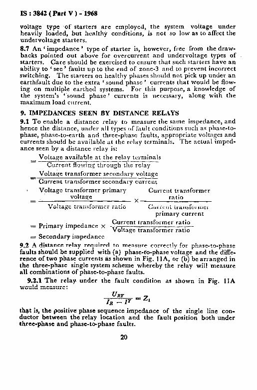
voltage type of starters are employed, the system voltage under heavily loaded, but !lealthy conditions, is not so low as to affect the undervoltage starters. 8.7 An (impedance ’ type of starter is, however, free from the draw- backs pointed out above for overcurrent and undervoltage types of starters. Care should be exercised to ensure that such starters have an ability to ‘ see ’ faults up to the end of zone-3 and to prevent incorrect switching. The starters on healthy phases should not pick up under an earthfault due to the extra ‘ sound phase ’ currents that would be flow- ing on multipl’e earthed systems. For this purpose, a knowledge of the system’s ’ sound phase ’ currents is nercssary, along with the maximum load current.
9. IMPEDANCES SEEN BY DISTANCE RELAYS
9.1 To enable a distance relay to measure the same impedance, and hence the distance, under all types of f’ault conditions such as phase-to- phase, phase-to-earth and three-phase faults, appropriate voltages and currents should be available at the relay terminals. The actual rmped- ante seen by a distance relay is:
Voltage available at the relay tcl.minals = -~-----.------_--_.---_. Current flowing through the relay
Voltage transformer secondary voltage Current transformer secondary currcnc Voltage tran;F;;Ter primary Currelit transformer
X ratio =
Voltage transformer ratio Currc:nt transformer primary current
Current transformer ratio = Primary impedance x -.-- Voltage transformer rat%7
= Secondary impedance 9.2 A distance relay required to measure correctly for phase-to-phase faults should be supplied with (a) phase-to-phase voltage and the diffe- rence of two phase currents as shown in Fig. I lA, or (b) be arranged in the three-phase single system scheme whereby the relay will measure all combinations of phase-to-phase faults.
9.2.1 The relay under the fault condition as shown in Fig. 1lA would measure :
URP IR - 1’
= 21
thst is, the positive phase sequence impedance of the single line con- ductor between the relay location and the fault position both under three-phase and phase-to-phase faults.
20

IS : 3842 ( Part V ) - 1968
9.2.2 Similarly, for phase-to-earth faults as shown in Fig. llB, if the relays were to measure positive phase sequence impedance Zr, addi- tional current, which is a function of the current transformer residual current ( Ia, ), should be fed into them. Thereforc, the relay measures
Since I& = 31, ( I0 = zero x
hase sequence current ) for a phase-to- earth fault, it may be shown at the factor ( K’ known as a earth fault residual compensation ’ should be:
20 - 21
32, where
Z,, is the zero phase sequence impedance.
With the above amount of compensation, it may be shown that in a multiple earthed system where value of lo is unknown and may change with switching conditions, automatic adjustment of the amount of com-
petisation may still be -achieved by adding i Z” - z, & 1
IRrr tQ
IB, by using a compensating transformer connected in the residual circuits.
- [R
Y Y
- IO B fB ,-
UBN - IRES -2 FAULl _;
I I A Phase-to-‘Phase Fault I I B Phase-to-Earth Fault
Fro. 11 CIRCUIT DIAGRAM FOR THE OPERATION OP DISTANCE RELAYS UNDER DIFFERENT FAULT CONDITIONS
10. APPLICATION OF DISTANCE RELAYS
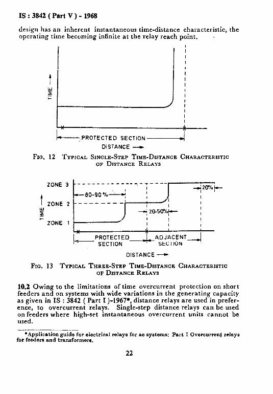
10.1 Of the various applications possible for a distance measuring relay, its application to transmission line protection is the most common. Instead of the inverse time-distance characteristic used earlier, ‘ step- ped ’ time-distance characteristics are now in use. The characteristibs may either be ‘ single-stepped ’ or ‘ three-stepped ’ as shown in Fig. 12 and 13 respectively. A distance measuring relay of conventional
21
IS : 3842 ( Part V ) - 1968
design has an inherent instantaneous time-distance characteristic, the operating time ,becoming infinite at the relay reach point. .
,PROTECTED SECTION -I
DiSTANCE -
Fm. 12 TYPICAL SINGLE-STEP TIME-DISTANCE CHARACTERISTIC OF DISTANCE RELAYS
ZONE 3
t ZONE 2
2
* ZONE 1
PROTECTED- - SECTION
DISTANCE -
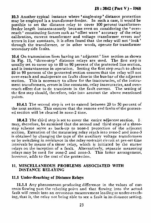
Fm. 13 TYPICAL THREE-STEP TIME-DISTANCE CHARACTERISTIC OF DISTANCE RELAYS
10.2 Owing to the limitations of time overcurrent protection on short feeders and on systems with wide variations in the generating capacity as given in IS : 3842 ( Part I )-1967*, distance relays are used in prefer- ence, to overcurrent relays. Single-step distance relays can be used on feeders where high-set instantaneous overcurrent units cannot be used.
*Application guide for electri&l relays for AC systems: Part I Overcurrent relays for feeders and transformera.
22
IS : 3842 ( Part V) - 1968
10.3 Another typical instance where ‘ single-step ’ distance protection may be employed is a transformer-feeder. In such a case, it would be possible to set the distance relay to cover 100 percent transformer- feeder length instantaneously because even on considering the ’ over- reach ’ constituting factors such as ‘ offset wave ’ accuracy of the relay calibration, current transformer and voltage transformer errors and errors in line constants, it is often found that the relay will not ‘ look ’ through the transformer, or in other words, operate for transformer secondary side faults.
10.4 On transmission lines having an c adjacent ’ line section as shown in Fig. 13, ‘ three-step ’ distance relays are used. The first step is usually set to cover up to 80 to 90 percent of the protected line section, and is instantaneous in operation. Setting the first step reach to about 80 to 90 percent of the protected section ensures that the relay will not over-reach and maloperate on faults close to the bus-bar of the adjacent section. This is necessary to allow for the inaccuracies, of the instru- ment transformers, errors in line constants, relay inaccuracies, and over- reach effect due to dc transients in the fault current. The setting of the first step should, therefore, take into account the above mentioned points.
10.4.1 The second step is set to extend between 20 to 50 percent of t,he next section. This ensures that the remote end faults of the protect- ed section will be cleared in zone-2 time.
10.4.2 The third step is set to cover the entire adjacent section. I.. may, therefore, be surmised that the second and third steps of a three- step scheme serve as back-up to zone-l protection of the adjacent section. Extention of the measuring relay reach into zone-2 and zone-3 is obtained by changing the taps of the auxiliary voltage transformers or by switching in resistance in the relay restraint circuit at pre-set time intervals by means of a timer relay, which is initiated by the starter relays on the inception of a fault. Alternatively, separate measuring relays may be used for zone-2 and zone-3. This latter arrangement, however, adds to the cost of the protection.
11. MISCELLANEOUS PROBLEMS ASSOCIATED WITH DISTANCE RELAYING
11.1 Under-Reaching of Distance Relays
11.1.1 Any phenomenon producing difference in the values of cur- rents flowing past the relaying point and that flowing into the actual fault will result into an erroneous measurement leading to under-reach- ing, that is, the relay not being able to see a fault in its distance setting.
23
IS:3842(PutV)-1968
This may happen under the following circumstances:
a) When there is an infeed at the next bus-bar; b) When there is fault impedance, usually present in the form of an
arc; and c) Earth faults on the secondary side of delta/star transformers
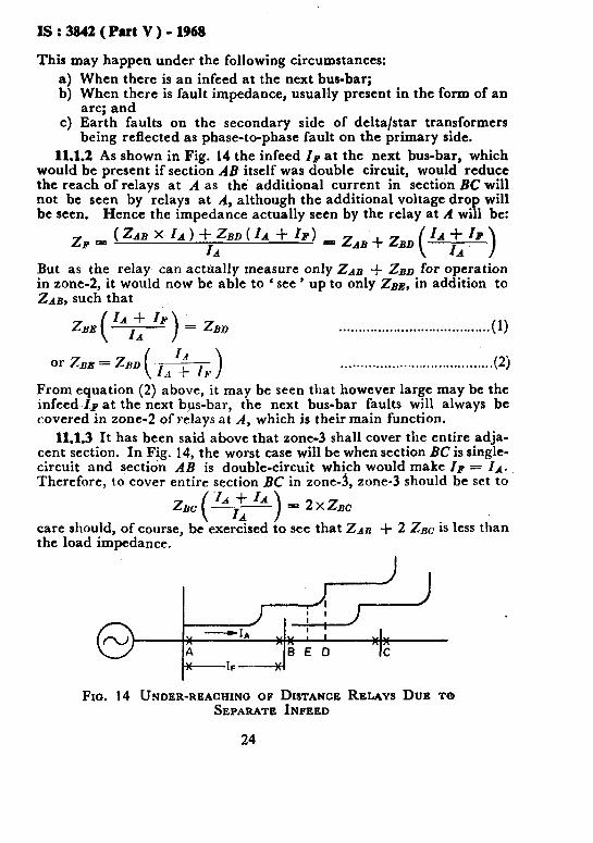
being reflected as phase-to-phase fault on the primary side. 11.1.2 As shown in Fig. 14 the infeed Zp at the next bus-bar, which
would be present if section A& itself was double circuit, would reduce the reach of relays at A as the additional current in section BC will not be seen by relays at A, although the additional voltage drop will be seen. Hence the impedance actually seen by the relay at A will be:
zF = (ZdB x Id) +$BD(zd + IF) =zABfzBD(zy) But as the relay can actnally measure only ZAB + ZBD for operation in zone-5 it would now be able to ‘ see ’ up to only ZB& in addition to ZAB, such that
z,E( “2 “) = ZBD . . . . . . . . . . . . . . . . . . . . . . . . . . . . . . . . . i . . . . . (1)
. . . . . . . . . . . . . . . . . . . . . . . . . . . . . . . . . . . . (2) From equation (2) above, it may be seen that however large may be the infeed Zp at the next bus-bar, the next bus-bar faults will always be covered in zone-2 of relays at A, which is their main function.
11.1.3 It has been said above that zone-3 shall cover the entire adja- cent section. In Fig. 14, the worst case will be when section BC is single- circuit and section AB is double-circuit which would make Zp = IA. Therefore, to cover entire section BC in zone-3, zone-3 should be set to
z,,( ““lf; “) = 2x&c ,
care should, of course, be exercised to see that 2~n + 2 ZBC is less than the load impedance.
Fro. 14 UNDER-REACHING OF DISTANCE RELAYS DUB TO SEPARATE INPEED
24
IS : 3842 ( Part V) - 1968
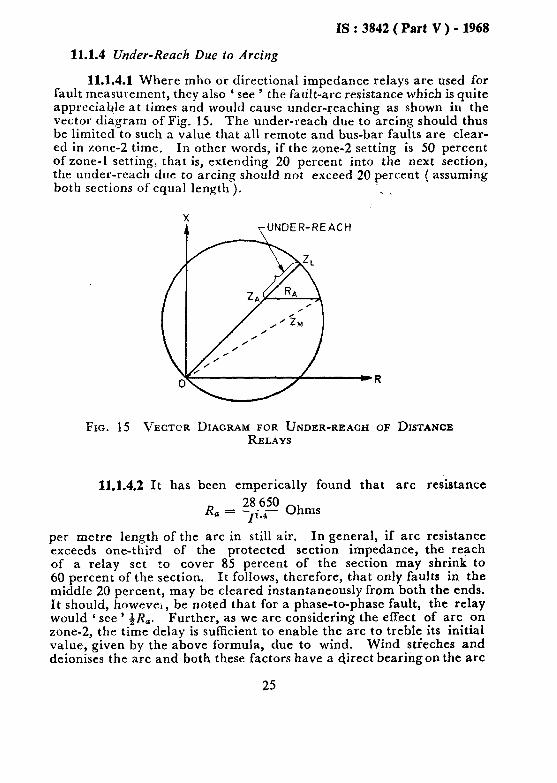
11.1.4 Under-Reach Due to Arcing
11.1.4.1 Where mho or directional impedance relays are used for fault measurement, they also ‘ see ’ the fault-arc resistance which is quite appreciable at times and would cause under-reaching as shown in the vector diagram of Fig. 15. Th e under-reach due to arcing should thus he limited to such a value that all remote and bus-bar faults are clear- ed in zone-2 time. In other words, if the zone-2 setting is 50 percent of zone-l setting, that is, extending 20 percent into the next section, the under-reach due to arcing should not exceed 20 percent ( assuming both sections of equal length ). . *
FIG. 15 VECTCR DIAGRAM FOR UNDER-REACH OF DISTANCE RELAYS
11.1.4.2 It has been emperically found that arc resistance
Ra = F 28 650 Ohms
per metre length of the arc in still air. In general, if arc resistance exceeds one-third of the protected section impedance, the reach of a relay set to cover 85 percent of the section may shrink to 60 percent of the section. It follows, therefore, that only faults in the middle 20 percent, may be cleared instantaneously from both the ends. It should, howeve‘, be noted that for a phase-to-phase fault, the relay would ‘ see ’ &Ra. Further, as we are considering the effect of arc on zone-2, the time delay is sufficient to enable the arc to treble its initial value, given by the above formula, due to wind. Wind stieches and deionises the arc and both these factors have a direct bearing on the arc
25

IS : 3842 ( Part V ) - 1968
resistance. Therefore, while calculating R, by the formula
( ‘ 1’ s11011ld be greater mho relays tolerance
(1’ being the length of the arc in -metre than the conductor spacing of a line ), to arcing may be increased by choosing the relay m;lximum torque angle to be less ( lagging) than the line angle. Modified impedance relays can be set to take care of arc compensntion without any under-reaching measurement :LS shown in l:i;<. 16.
FIG. 16 MODIFIED I~~PEDANCE RELAY CHARACTERISTICS WITH
AND WITHOUT ARC COMPENSATION
11.1.4.3 Another method of increasing the tolerance of mho relays to arcing is to polarize them with voltage from another phase(s), that is, from unfaulted phases. This alters the reach of the mho relay under different fault conditions along the R axis. Thus the relay allows for more arc resistance.
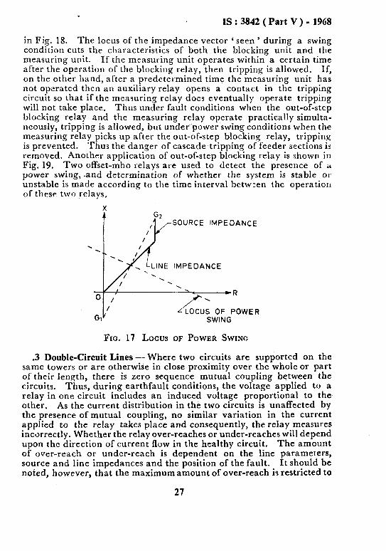
11.2 Power Swings -Distance protection, not being a true unit protec- tion, is affected by power swings on the system and may operate under these conditions. The locus ofa power swing on the polar diagram is shown in Fig. 17. It will be noted that the locus of the power swing is at right angles to the general direction of the line impedances. In general, distance relays having mho characteristics are less susceptible to operation on power swings because of their narrower characteristics. If the system goes out of step, however, these relays will also operate. Because of this, special measures are taken to block operation during a power swing either by using an ohm-blinder relay as shown in Fig. 2 or by using an out-of-step blockin g relay. The latter arraugement is shown
26
IS : 3842 (Part V) - 1968
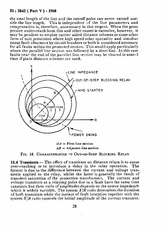
in Fig. 18. The locus of the impedance vector ‘ seen ’ during a swing condition cuts the characteristics of both the blocking unit and the measuring unit. If the measuring unit operates within a certain time after the operation of the blocking relay, then tripping is allowed. If, on the other hand, after a predetermined time the measuring unit has not operated then an auxiliary relay opens a contact in the tripping circuit so that if the measuring relay does eventually operate tripping will not take place. Thus under fault conditions when the out-of-step blocking relay and the measuring relay operate practically simulta- neously, tripping is allowed, but underpower swing conditions when the measuring relay picks up after the out-of-step blocking relay, tripping is prevented. Thus the danger of cascade tripping of feeder sections is removed. Another applicatron of out-of-step blocking relay is shown in Fig. 19. Two offset-mho relays are used to detect the presence of a power swing, .and determination of whether the system is stable OI unstable is made according to the time interval between the operation of these two relays.
SOURCE IMPEDANCE
0 / /
G,/ SWING
FIG. 17 Locus OF POWER SWING
.3 Double-Circuit Lines --Where two circuits are supported on the same towers or are otherwise in close proximity over the whole or part of their length, there is zero sequence mutual coupling between the circuits. Thus, during earthfault conditions, the voltage applied to a relay in one circuit includes an induced voltage proportional to the other. As the current distribution in the two circuits is unaffected by the presence of mutual coupling, no similar variation in the current applied to the relay takes place and consequently, the relay measures incorrectly. Whether the relay over-reaches or under-reaches will depend upon the direction of current flow in the healthy circuit. The amount of over-reach or under-reach is dependent on the line parameters, source and line impedances and the position of the fault. It should be noted, however, that the maximum amount of over-reach is restricted to
27
IS : 3842 ( Part V ) - 1968
the total length of the line and the cut-off point can never extend out- side the line length. This is independent of the line parameters and compensation is, therefore, unnecessary in this respect. When the pros- pective under-reach from this and other causei is excessive, however, it may be prudent to employ carrier aided distance schemes or some other form of unit protection where high speed relay operation and simulta- neous fault clearance by circuit breakers or both is considered necessary for all faults within the protected section. This would apply particularly where the parallel line section was followed by a short line. In this case faults near the end of the parallel line section may be cleared in zone-3 time if plain distance schemes are used.
X
r-LINE IMPEDANCE
OUT-OF-STEP
MHO STARTE
BLOCKING
R
RELAY
OA = First line section AB = Adjacent line section
FIG. 18 CHARACTERISTICS OF OUT-OF-STEP BLOCKING RELAY
11.4 Transients -The effect of transients on distance relays is to cause, over-reaching or to introduce a delay in the relay operation. The former is due to the difference between the current and voltage tran-. sients applied to the relay, whilst the latter is generally the result of transient saturation of the protective transformers. The current and voltage transients at a relaying point due to a fault have the same time constants but their ratio of amplitudes depends on the source impedance which is widely variable. The system X/R ratio determines the duration of both transients while the instant of fault inception together with the system X/R ratio controls the initial amplitude of the current transient.
28

IS : 3842 ( Part V ) - 1968
The amplitude of the voltage transient is inversely proportional to the source to line impedance ratio but also. increases as the difference in the source and line angles increases. In a homogeneous system there is no transient voltage as the source and line angles L-e identical.
X MHO STARTER OF DISTANCE
PROTECTION
FIG. 19 OUT-OF-STEP BLOCKING SCHEME USING Two OFFSET- MHO ELEMENTS (A AND B)
The effect pf these transients is to increase the peak and rms values of current and voltage applied to the relay during the first few cycles of a fault. The current transient tends to increase the operating force and so causes over-reach, whilst the voltage transient increases the res- traint force and causes under-reach. Since the voltage transient is always lower in magnitude, the net result is towards over-reach.
Where transient instability of a relay is merely due to mismatch between the transients in the current and voltage inputs, it may be corrected by either matching the transients by the use of secondary replica impedances or alternatively, by eliminating the transients altogether using filters; in the latter case at the cost of time delay.
Unfortunately, transients may cause saturation in current trans- formers due-to the increased flux swing and this results in a possible delay in relay operation of several cycles. This condition is quite intolerable in situations where system instability may result from delay in fault clearance. Current transformer should be designed to with- stand this flux swing without saturation when ’ 1 cycle ’ distance relays are used.
29

IS : 3842 ( Part V ) - 1968
11.5 Operating Time Characteristics - III practical relays, as the relationship between the operating current and restraint voltage direcfl! affects the relay operating time, it varies with fault position and inplli current, being short for large inputs near the relaying point and lo:g for small inputs near the reach point. Tl.pe of comparator used deter- mines h,ow sensitive a particular relay is and how far its operating time is affected by fault position and input current.
It is customary to present inforrnation on operating time by contour curves, similar to those shown in Fig. 20. From this figure, operating time may be determined for various fault positions and for various values of system source to line impedance ratios ZS/ZJ,. This mct?loci of representing operating time is now verv common.
-RELAY BOUNDARY CHARACTERISTiC
:t; 100 IAIm
Ez 8G
zid =KK 60
OIA
5: 4o 25 20
v ccc
$tti 1 10 100
lJ.Y) a, SOURCE TO LINE IMPEDANCE RATIO+-
( )
FIG. 20 TYPICAL OPERATING TIME CHARACTERISTICS
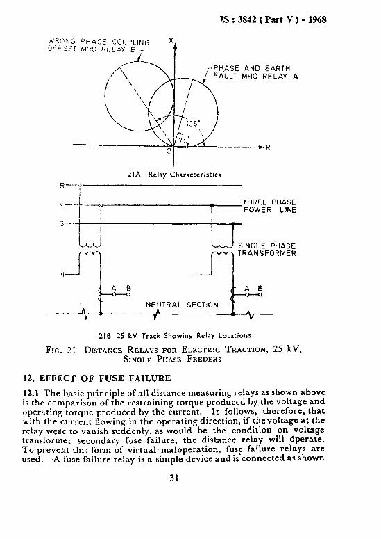
11.6 Application of Distance Relays to Electric Traction - Use of dis- tance relays on single phase 25 kV railway overhead feeders has become common. A typical application is shown in Fig. 21. Two distance relays are normally used, one for phase-to-earth faults and second to guard against wrong phase coupling in case neutral section is acci- dentally ‘ bridged ‘. These relays have single instantaneous zone as no grading is involved.
Phase-to-earth fault relay is similar to the distance relays for three- phase lines. However, wrong phase coupling relay is normally provided with a maximum torque angle of 125” to 145”. It is preferable to provide a forward ‘ offset’ for this relay to prevent it from operating on phase-to-earth faults.
30
!S : 3842 ( Part V ) - 1968
R---y
2lA Relay Characteristics
J- +n TRANSFORMER
‘I/
(- A B - A B
c: _ O 0
n 6 NEUTRAL SECTION -
A A V V
2IB 25 kV Track Showing Relay Locations
Fro. 31 DISTAIWE RELAYS FOR ELECTRIC TRACTION, 25 kV, SINGLE PHASE FEEDERS
12. EFFECT OF FUSE FAILURE
12.1 The basic principle of all distance measuring relays as shown above is the comparison of the restraining torque produced by the voltage and operating torque produced by the current. It follows, therefore, that with the current flowing in the operating direction, if thevoltage at the relay were to vanish suddenly, as would be the condition on voltage transformer secondary fuse failure, the distance relay will dperate. To prevent this form of virtual maloperation, fuse failure relays are used. A fuse failure relay is a simple device and is-connected as shown
31

IS : 3842 ( Part V ) - 1968
in Fig. 22. On one or more main voltage transformer fuse blowing, the fuse failure relay will be energized. Fuse failure relavs have nor- mally closed contact which may be wired in srries with -the distance relay trip circuit to block the undesirable tripping impulse. The fuse failure relay should be provided with another pair of electl.icall~ separate contacts so that an alarm may be sounded.
TRIP CIRCUIT
dz!z ALARM CIRCUIT
A = Fuse failure relay B = Distance relay voltage coils
FIG. 22 CONNECTIONS FOR FUSE FAILURE RELAY
12.2 It should, however, be ensured that the operating time of voltage transformer fuse failure relay is shorter than the distance relay zone-l operating time otherwise the fuse failure relays will get ‘beaten ’ by the distance protection relays, which it ii supposed to prevent from maloperation.
12.3 When fuse failure relay or miniature circuit-breakers are used, it should be ensured that the operating time of the same is shorter than the protection operating time and further more the starters do not maloperate under high resistance voltage transformer faults.
32
IS : 3842 ( Part V ) - 1968
13. DISTANCE-RELAYS IN CONJUNCTION WITH AUTO- RECLOSING AND CARRIER CHANNEL
13.1 Distance relays are often required to operate in donjunction with circuit-breaker autorreclosing schemes to avoid unnecessary interrup- tion of supply on transient faults which are by far the most predominant faults on overhead transmission systems. The requiremmts ofsuccess- ful auto-reclosing schemes are:
a) Simultaneous and ‘ instantaneous ’ de-energisation of the faulted line section from both the ends;
b) Allow a certain and minimum amount of ‘ dead ’ time to let the fault arc deionise; and
c) Close both ends of the line simultaneously.
13.1.1 For an auto-reclose to be successful, that is, the two systems pulling into step again after the momentary disruption it follows that the tripping and closing operations at the two ends should be ‘ simulta- neous ’ and the time delay under 13.1(b) should be as low as practicablr.
13.1.2 The requirements of 13.1( ) a and 13,1(c) are achieved by liuk- ing the protection at the two ends of a line by means of a ’ carrier’ channel. The carrier channel principle is used in the following forms;
a) Carrier-intertripping,
b) Carrier-blocking, and
c) Carrier-acceleration.
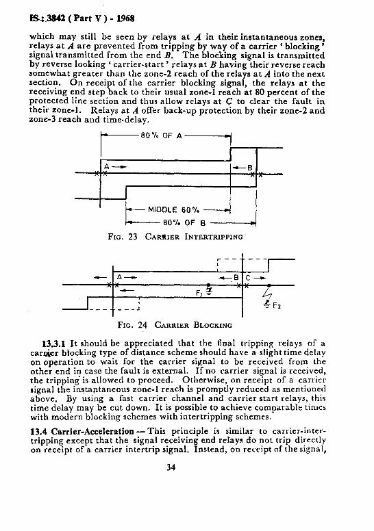
13.2 Carrier-Intertripping - Carrier-intertripping principle is shown ir. Fig. 23. The distance relays at the two ends A and B cover about 80 percent of the line length in their instantaneous zone-l. Therefore, faults occurring in the middle 60 percent of the lin; section are ‘ seen ’ by both the ends in zone-l and their tripping is simultaneous. However, for faults occurring in the end 20 percent sections, the relay nearest the fault locates it in its zone-l while the remoter relay locates the same in its zone-2. The nearer tripping relay is therefore made to send a carrier signal to the remoter nontripping relay to bring about simultaneous tripping of the whole line section. Once the two ends trip simulta- neously, the auto-reclose relays take over.
13.3 Carrier-Blocking -One of the carrier-blocking principle is shown in Fig. 24. Here the carrier signal is utilized slightly differently. The distance relays at A and B are normally made to ‘ sit ’ in zone-2, that is, they are made able to I see ’ up to 140 percent of the line length instanta- neously. Therefore, for a fault anywhere along the line section, the relays at two ~nd3 trip simultaneously and the auto-reclosing sequences are initiated. However, for faults in the ad,jacent section, say at F,,
33
S4842 (Part V ) - 1968
which may still be seen by relays at A in their instantaneous zones, relays at A are prevented from tripping by way of a carrier ( blocking’ signal transmitted from the end B. The blocking signal is transmitted by reverse looking ‘ carrier-start ’ relays at B having their reverse reach somewhat greater than the zone-2 reach of the relays at A into the next section. On receipt of the carrier blocking signal, the relays at the receiving end step back to their usual zone-l reach at 80 percent of the protected line section and thus allow relays at C to clear the fault in their zone-l. Relays at ,4 offer back-up protection by their zone-2 and zone-3 reach and time-delay.
A- nr\ nfi
~Mlcxu~6~~B~~-Bj
FIG. 23 CARRIER INTERTRIPPING
r--$---,-
- A--w +--B C--c
- F1 3 I
____. - s-J + F2
FIG. 24 CARRIER BLOCKING
13.3.1 It should be appreciated that the final tripping relays of a car&r blocking type of distance scheme should have a slight time delay on operation to wait for the carrier signal to be received from the other end in case the fault is external. If no carrier signal is received, the tripping is allowed to proceed. Otherwise, on receipt of a Carrie1 signal the instantaneous zone-l reach is promptly reduced as mentioned above. By using a fast carrier channel and carrier start relays, this time delay may be cut down. It is possible to achieve comparable times with modern blocking schemes with intertripping schemes.
13.4 Carrier-Acceleration -This principle is similar to carrier-inter- tripping except that the signal receiving end relays do not trip directly on receipt of a carrier intertrip signal. Instead, on receipt of the signal,
34

IS : 3842 ( Part V ) - 1948
the zone-l reach of the relays is instantly extended to cover the entire protected section and tripping takes place after the relays at the signal receiving end have actually measured a fault. This principle introduces a slight time delay for remote end tripping as compared with the inter- tripping principle where tripping takes place as soon as the carrier is received.
13.5 From signalling point of view, the carrier-blocking principle is Superior. The signal is transmitted over a healthy line and the only potential noise problem is during ‘internal fault; at any other time,noise merely causes a harmless blocking signal. The intertrip and acceleration schemes on the other hand, always signal through a short circuited transmission line. Carrier-intertripping schemes are still sometimes favoured because they are cheaper than carrier-blocking schemes as the latter have to have additional reverse looking ‘ carrier start ’ relays apart from the usual set of measuring relays. However, for extra high voltage lines ( 220 kV and above ) carrier-blocking schemes are generally preferred.
14. APPLICATION OF DISTANCE RELAYS TO TEED LINES
14.1 Application of distance relays to teed lines deserves careful thought and co-ordination. In the example given in Fig. 25, a fault at F may be seen by all the three relays, at A, B and C, in their zone-l. Ideally speaking, line AB should not trip. This is where ‘ carrier-blocking ’ principle is most usefully employed. The relays at C may have a carrier- blocking transmitter whereas relays at A and B may be the conventional carrier-blocking schemes with reverse looking ‘ carrier start ’ relays to take care of faults on the adjacent sections. With such an arrangement for faults down the line CD which fall within the instantaneous reach of all the three relays, station C will transmit a blocking signal to stations A and B and clear the fault first. Line CD may then have its own auto-reclosing scheme.
A B nr. An
- 11 C -
D b t FIG. 25 APPLICATION OF DISTANCE RELAYS TO TEED LINES
14.2 Carrier-intertripping principle may also be employed here but it would necessitate foregoing of high speed auto-reclosing at C. For a
35

IS : 3842 (Part V ) - 1968
fault at F, all the three stations will trip. A and B should auto-reclose as quickly as possible whereas C may either not reclose automatically at all, or have delayed anto-reclosing.
14.3 While choosing settings for such a multi-terminal line, it should be borne in mind that if the tee-off has a transformer right at thejunction, i Len the ‘ instantaneous ’ reach of the relays at A and B should not normally extend beyond the transformers(s) at C. The lower the trans- former impedance, for example, more units in parallel at a tee-off, the lower will be the instantaneous coverage possible for the main line relays at A and B.
14.4 It has been assumed in above discussion that there is no source connected at end D. Protection of each teed feeder requires special consideration and depends on various factors, for example, whether teed feeder is connected to a source, w.hether there is a transformer at ‘ tee-off ‘, etc.
15. APPLICATION OF DISTANCE RELAYS FOR SINGLE-POLE AND THREE-POLE AUTO-RECLOSING
15.1 In applications where it is felt that single-pole auto-reclosing is desirable from system stability point of view, distance protection may be designed to meet this requirement. In case of ‘ switched ’ schemes the ‘ pole ’ selection is done by the starter relays auxiliaries, whereas in case of a non-switched scheme, it is provided by the respective phase measur- ing relays or their auxiliary trip relays. It is, however, ensured that for faults involving more than one phase, all the three phases are tripped as shown in Fig. 26, The function of contacts R,, Yz and B, may also be performed by a ‘ 1 phase - 3 phase selector switch’ which may be locat- ed either on the relay panel or at the circuit-breaker itself.
TRIP R
TRIP Y
.--x+-cc TRIP B
FIG. 26 APPLICATION OF DISTANCE RELAYS FOR SINGLE- AND THREE-PHASE AUTO-RECLOSING
36

IS : 3842 ( Part V ) - 1968
16. INSTRUMENT TRANSFORMER CONNECTIONS
16.1 Impedances presented to the relay under different fault conditions depend upon the current transformer and voltage transformer connec- tions and whether zero sequence compensation is used or not. These facts should be taken into consideration while setting the relays.
17. A TYPICAL EXAMPLE OF DISTANCE RELAY APPLICATION
17.0 General -Fig. 27 shows a typical 66133111 kV network. The calculation necessary ior application of distance relays are carried out step by step. The requirements of the two lines, A and B, are identical.
As stated previously, it is useful for a manufacturer to declare the minimum voltage across the relay coils at which the relay will maintain the accuracy of its calibration within specified limits. In the system shown in Fig. 27, minimum voltage will occur when with minimum generation on the 66 kV side, given by the minimum fault level, only one 66133 kV transformer is feeding the 33 kV bus-bar.
17.1 Step J- Check whether 80 percent of the proposed line length to be protected falls within the setting range available on the measuring relays:
80 percent of line impedance = 0.8 x 5.6 = 4.48 Ohms
Therefore, impedance seen by the relay, 2s = 4.48 x
Current transformer ratio Voltage transformer ratio
or 2s = 4’48 x 598 Ohms
This value should fail within the setting range of the relay.
17.2 Step II - Check the minimum voltage at the relay for a fault at zone-l reach point for three-phase fault.
4
b)
4
( 33 )2 = jz.18 Ohms = 500
66133 kV transformer impe- dance at 33 kV bus-bar = (33))
30 x 7 = j3.64 Ohms
Line impedance for a fault at 80 percent point = ( 2.5 + j5.0 ) [ i:i t ::z ,’
= ( l-2 + j2.4 ) Ohms
37

IS : 3842 (Part V) - 1968
SUB-SfAl
66 kV SYSTEM
MINIMUM FAULT LEVEL 500 MVA
PERCENlAGE REACT-
33 kV BUS-BAR
I 400/l CURRENT TRANSFORMER
33 kV/llb V VOLTAGE TRANSFORMER
33 kV BUS-BAR
RADIAL FEEDERS 10 WA 33/llkV TRANSFORMER
PERCENTAGE REACTANCE : 19
cl1 kV BUS-BAR
FIG. 27 CIRCUIT DIAGRAM OF THE EXAMPLE ON APPLICATION 01: DIWANCE RELAYS
38
IS : 3842 ( Part V ) - 1968
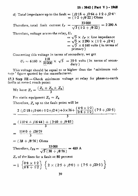
d) Total impedance up to the fault = (j2.18 + j3.64 + l-2 -I- j2'4 ’ = ( 1.2 +j8*22 ) Ohms
Therefore, total fault current IF = 33 000
d/3 ( 1.2 + j8.22 ) =.2290 A
Therefore, voltage across the relay, U, = QT x IF x line impedance
= &I x 2290 x (1.2 + j2.4) = 47 x 6 160 volts ( in terms of
primary )
Converting this voltage in terms of secondary, we get
110 - u, = 6160 x 33000 x 1/3 = 35.5 volts ( in terms of secon-
- dary )
This voltage should be equal to or higher than the ‘minimum d-
tage ’ figuse quoted by the manufacturer.
17.3 Step III.- Check minimum voltage at relay for phase-to-earth faults at zone-l reach point:
We have Z, = (zI+zs+ 20) 3
For static equipment Zr = 2s
Therefore, 2, up to the fault point will be
2 (j2*18+j3*64+1*2+j2*4)+3x36+ (@8+ 1.2) ( 0.8 X 1.2) ( 7.5 _+_j20.5)
= 3
= ( 110’4 $- .jl6.44 ) + ( 3.60 + j9.85 ) 3
= 114.0 + ,j26*29 -__- 3
= ( 38 + j8.76 ) Ohms
Therefore, IFE = 33000
2/y-( 38 f j8.76 ) = 489 A
2, of the lines for a fault at 80 percent
= Q I O-8 x 1.2 .--I_ - ~0.8 + 1.2
r 2 x ( 2.5 + j5.0 ) + ( 7.5 i- j'rO-5 ) >
39

IS : 3842 ( Part V ) - 1968
= 4 ( 2.4 + j4.8 + 3.6 + j9.85 )
= 4 ( 6.0 + j14.65 )
= (2.0 + j4-88) Ohms
= 5-3 Ohms
Therefore U, = 489 x 5.3 x 3s0 = 8.6 volts ( in terms of
secondary )
This value U, should he equal to or greater than the one specified by the manufacturer.
17.4 Step IV -Determination of Relay Settings -It should be noted that all relays are calibrated in positive sequence impedance.
17.4.1 To set zone-l to cover 80 percent of the protected line:
Primary impedance Z1 = 2’5 $- j5.0
Primary impedance in terms of secondary ( 80 percent of the protected line ) = 0.8 x ( 2.5-t j5.0 ) x ‘F x $$&-
= 2.67 + j5.34
= 5’98 /$20 Ohms
Therefore, reactance relays should be set at 5.34 Ohms.
Since.the line angle is 63*5”, mho relays with 60” maximum torque angle will’be most suitable and they should be set at:
5.98 cos ( 63.5 - 6(-j” ) = “’ Ohms
17.4.2 To set zone-2 to cover the protected line plus 50 percent of the next line section:
Primary impedance Zs = ( 2’5 + j5.0 ) $- 3 ( 3.5 + j7.0 )
= 4.25 + j8.5
Primary impedance in 110 terms of secondary = (4.25 + ,j8*5 ) x F x 33000
= ( 5.66 -t_ ,jl1*33 ) Ohms
= 12.7 /Ej” Ohms
Therefore, reactance relays zone-2 reach should bc set to Il.33 Ohnls.
40

Is:3842(Part V)-1968
The mho relays, with 60” mriximum torque angle should be set to:
127 = Gas ( 63.5 - 60 )
= 12.8 Ohms
t 13.0 Ohms
17.4.3 To set zone-3 to cover the protected line plus 125 percent of the next line section:
2s (in terms of secondary ) = ( 25+jS*O)+1’25 ( 3’5+j7*0) $X -!!?-
33000
= 9.18 + ji8.35 Ohms
= 20.5 /E Ohms
Therefore, reactance relays should be set at about, say, 20 Ohms. The mho relays should be set at:
20.5 Cos ( 63.5 - 60 )
= 21 Ohms.
17.5 Step V -To check for positive operation of starters for faults at or just beyond zone-3 reach point:
Z1 = j2.18 + j3.64 + 3 ( 2.5 + jS.0 ) + 1.25 ( 3.5 -C j7.0 )
= ( 5.62 + ,j17*07 ) Ohms
Line volts Therefore, line current = ------- =
33 000 Loop Impedance 2 (5*62+j17*07)
33 000 __ = 915 A
= 36.0 915
Therefore, current in one line = 2 = 458 A
458 = 4oo A ( in terms of secondary)
= 1.14 A ( in terms of secondary)
Should this setting be considered too low in relation to.the feed at substation ‘ B ‘, then ‘ mho ’ or impedance type starters should be used, wit;1 the same setting or ju$t greater than zone-3 setting that is, 21 Ohms.
17.6 Step VI - Zone-2 and Zone-3 Discrimination - If the zone-2 or zone-.3 reaches of the distance ielays look beyond the 33/l 1 kV trans- formers, then the time delay of zone-2 and zone-3 should grade with the 11 kV protection. In this instance:
(33Y Parallel impedance of transformers = so x -20
= j5.45 Ohms.
41

IS:3842(Part V)-I%8
Therefore, impedance from the relaying point = ( 2.5 + j5.0 ) + j5’45
= ( 2.5 + j10.45 ) Ohms ( primary ) In terms of secondary, this impedance is:
= (2.5 + j10.45) ‘F x -!-!& 33 000
= ( 3.33 + j13.9 ) Ohms Reactance relays zone-2 reach is worked out to be Il.53 Ohms.
Therefore, zone-2 will not look into 11 kV faults. Zone-3 reactance relays reach is worked out to be 20 Ohms. As the fault reactance is only 13.9 Ohms, zone-3 relays will see 11 kV side faults; hence zone-3 time should be graded with the 11 kV protection. Mho relays will be similarly,affected.
17.7 Step VII - To Check Uoder-Reach of Zone-2 and Zone-3 - Becausr zone-2 and zone-3 fault currents will be shared by the two parallel lines equally, for zone-2 faults, the relays will actually see:
( 2.5 + j5.0 ) + 0.5 ( 3.5 + j7.0 ) x ) = ( 3.375 + j6’75 ) Ohms ( in terms of primary )
= ( 4.0 + j9.0 ) Ohms ( in terms of secondary ) But Zone-2 reactance relays are actually set at 11.33 Ohms
Therefore, percentage under-reach = 11.33 - 9’0
Il.33 - = 20.6 percent
Similarly, the measured itipedance for zone-3 will be
( 2’5 + j5.0 ) + 1.25 ( 3.5 + j7.0 ) x 4 = (4.69 + j9.38 ) Ohms ( in terms of primary ) = ( 6.25 + j12*5 ) Ohms ( in terms of secondary )
But zone-3 reactance relays are actually set at 20 Ohms. *
20-12.5 Therefore, under-reach for zone-3 = 2. = 37.5 percent.
Therefore, as already pointed out earlier, if load impedance permits, zone-3 reach should be set to cover 125 percent of the adjacent line section taking into consideration the division of fault current along the parallel lines. That is, the zone-3 should be set at:
( 2.5 + jS*O ) + 2 x 1.25 ( 3.5 + j7’0 ) = 15-O f j30.0 Ohms ( in terms of secondary )
A similar check can be carried out for mho relays.
42
BUREAU OF INDIAN STANDARDS
Heedquerters : Manak Bhavan. 9 Bahadur Shah Zafar Marg. NEW DELHI 110002
Telephones : 331 01 31 Telegrams : Manaksanstha 331 13 75 (Common to all Offiis)
Regional Offices :
Central : Manak Bhavan, 9, Bahadur Shah Zafar Marg. NEW DELHI 110002
l Eastern - l/14 C.I.T. Scheme VII M. ’ ‘4.’ D. Road, Maniktola. CALCUTTA 700054
Northern : SC3 445-446, Sector 35-C, CHANDIGARH 160036 Southern : C.I.T. Camous, IV Cross Road, MADRAS 600113
t ‘W&tern : Mane!c~!&a, ES MIDC Marol, Andheri (East), &cl 111 >,.., I ~OCO93
‘Pushpak’, Nclrnlohamed Shaikh Marg, Khanpur. AHMADABAD 380001 t Peertya Incci.:, s%.sa, 1 st Stage. Bangalore-Tumkur Road,
BANGALOHt obcO58 Gangotri Complex, 5th Floor, Bhadbhada Road, T.T. Nagar.
BHOPAL 462003
Plot No. 82/83, Lewrs Road, BHUBANESHWAR 751002 Kaiai Kathir Ruiidina. 6/48-A Avanasi Road, COIMBATORE 641037 Quality Marking CeGire; N.H. IV, N,I.T., FARIDABAD 121001 Savitri Complex. 116 G. T. Road, GHAZIABAD 201001 5315 Waro 31~1 29, T;.G Barua Road. 5th By-lane,
GUWAhA I i it;1003 5.8-5tic; I ;.! Gupta Marg, ( Nornp:: .y station 9oad )
HYDER,A!-‘AD 500001 R14 Yudti : :fiarg, C Scheme, JAIPUR 302Oe,
1171418 B Sarvodaya Nagar, KANPUR’208005
Plot No. A-S, House No. 561/63 Slndnu Nagar, Kanpur Roao. LUCKNOW 226005
Patliputra Illdustrlal Estate, PATNA 8X013
Dtstrict Industries Centre Complex, Bagh-e-Ali Maidan. SRINAGAFL 190011
T. C. No. 14/1421’, University P. 0.. Palayam. THIRUVANANTHAPURAM 695034
/nspection Offices (With Sale Point) : Pushpanjali. First Floor, 205-A West High Court Road.
Shankar Nagar Square, NAGPUR 440010 Institution of Engineers (India) Building, 1332 Shivaji Nagar.
PUNE 411005 --- ---- ‘Sales Office Calcutta is at 5 Chowringhee Approach, P. 0. Princep Street, CALCUTTA
t Sales Offlce is at Novelty Chambers, Grant Road, BOMBAY
i Sales Office is at Unity Building, Narasimharaja Square, BANGALORE
Telephone
! 331 01 31
“3”: is3 z
21843 41 29 16
6 32 92 95
2 63 48 39 49 55
55 40 n
53627 2 67 05
B-71 19 96 33177
23 10 83
6 34 71 21 68 76
5 55 07
6 23 05
621 04
62 51 71
5 24 35
27 68 00
89 65 28
22 39 71
I.e9rography Unit, Bi5 New Delhi, India