Embed Size (px)
Citation preview

Disclosure to Promote the Right To Information
Whereas the Parliament of India has set out to provide a practical regime of right to information for citizens to secure access to information under the control of public authorities, in order to promote transparency and accountability in the working of every public authority, and whereas the attached publication of the Bureau of Indian Standards is of particular interest to the public, particularly disadvantaged communities and those engaged in the pursuit of education and knowledge, the attached public safety standard is made available to promote the timely dissemination of this information in an accurate manner to the public.
इंटरनेट मानक
“!ान $ एक न' भारत का +नम-ण”Satyanarayan Gangaram Pitroda
“Invent a New India Using Knowledge”
“प0रा1 को छोड न' 5 तरफ”Jawaharlal Nehru
“Step Out From the Old to the New”
“जान1 का अ+धकार, जी1 का अ+धकार”Mazdoor Kisan Shakti Sangathan
“The Right to Information, The Right to Live”
“!ान एक ऐसा खजाना > जो कभी च0राया नहB जा सकता है”Bhartṛhari—Nītiśatakam
“Knowledge is such a treasure which cannot be stolen”
“Invent a New India Using Knowledge”
है”ह”ह
IS 6924 (1973): Code of Practice for the Construction ofRefuse Chutes in Multistoreyed Buildings [CED 24: PublicHealth Engineering.]


X$:6924-1973
Indian Standard
CODE OF PRACTICE FOR THE CONSTRUCTION OF REFUSE CHUTES
IN MULTISTOREYED BUILDINGS
( Second Reprint FEBRUARY 1989 )
XX 69.027.5:69,032.22:69.001.3
@ Copyright 1973
BUPEAU OF INDIAN STANDARDS hlANAK BHAVAN, 9 BAHADUR SHAH ZAFAR MAR0
NEW DELHI 110002
Gr 3 Jul9 1973

IS : 6924 - 1973
Indian Standard
CODE OF PRACTICE FOR THE CONSTRUCTION OF REFUSE CHUTES
IN MULTISTOREYED BUILDINGS
Water Supply and Sanitation Sectional Committee, BDC 24
Chairman
Pnow N. MA JUMDER
Representing
All India Institute of Hygiene & Public Health, Calcutta
Members
Sanr H. R. BADYAL Indian Iron & Steel Co Ltd, Calcutta SHRI K. R. PANDALAI ( Alternate )
SHRI M. R. BAJIKA.R In personal capacity ( Rustom Building, 29 Veer Nariman Road, Bombay I )
SHRI ANAND UPENDRA (Alternate) . SHRI J. R. BHALLA
SHRI U. J. BHATT DR B. V. BHOOTA
SHRI M. L. SHAE ( .-&raate ) Cawv ENQINEER
C~IIEF ENGINEER ( WATER )
Indian Institute of Architects, Bombay Institution of Engineers ( India ), Calcutta Dorr-01 ver ( India ) Ltd, Bombay
Local Self Government Engineering Department, Lucknow
Public Health Engineering Department, Government of Jammu 8t Kashmir
Municipal Corporation of Delhi DRAINAQE ENQI~EER ( Alternate )
SITRI R. C. P. CHOVDRARY Engineers India Ltd, New Delhi SHRI K. RUDRAPPA ( Alternate )
. DEPUTY ADVISER ( PHE ) Ministry of Health & Family Planning SERI V. A. ANANDADOUS ( Alternate )
SRRI DEVENDRA SIN~H In personal capacity ( Model Engineers, 5th Floor,
SHRI M. DURAIRAJAN .Nanabhai Mansion, Sir P. M. Road, Bombay 1 )
Tamil Nadu Water Supply & Drainage Board, Madras
SERI M. Y. MADAN SHRI C. E. S. RAO (Alternate)
Hindustan Construction Co Ltd, Bombay
$ SHRI S. K. MAJUMDER Public Health Engineering Department, Government
of West Bemral SHRI B. K. MALHAN In personal cap&ity (D-20 South Extekion, Part II,
.New Delhi 49 )
( Continued on page 2 )
Q CoBright 1973
BUREAU OF INDIAN STANDARDS This pubIication is protected under the Indian Copyright Act (XIV of 1957) and reproduction in whole or in part by any means except with written permission of the publisher shall be deemed to be an infringement of copyright under the said Act.

IS : 6924 - 1973
( Continuedfrom page 1 ) I
Members Repesenting
SRRI H. S. L. MWRTRY Public Works Department, Government of Mysore > SHRI K. S. NAXAYANAN Central Public Works Department
SHRI V. P. NARAYANAN NAYAR Public Health Engineering Department, Government of Kerala
SHRI N. S. BHAIRAVAN (Alternate ) SHRI S. K. NEOQI Calcutta Metropolitan Planning Organization,
Calcutta DR S. V. PATWARDHAN University of Roorkee SHRI V. RAMAN Central Public Health Engineering Research Institute
C CSIR ). Naeour SRRI V. HAXUMANULU (Alternate ) ’ ” “*
SRRI D. R. JAOANNATH RAO Public Health Department, Government of Madhya Pradesh
SHRI D. V. S. MURTHY ( Alternate ) L. R. Sehgal & Co, New Delhi Engineer-in-Chief’s Branch, Army, Headquarters
SHRI L. R. SEHQAL COL K. B. SETH
SHRI R. B. SUJAN ( Alternate ) SHRI JAOMOHAN LAL SETHI Public Health Engineering Department, Government
of Haryana SHRI M. T. SHETTY SI~R~ D. R. SINGAL TOWN ENGINEER, CHITTARANJAN
LOCOMOTIVE WORKS SHRI P. VISWANATHAN SERI D. AJITHA SIMHA,
Director ( Civ Engg )
Water Supply and Sewerage Board, Bangalore Public Works Deuartment, Government ef Punjab Ministry of Railways
Corporation of Madras Director General, IS1 (Ex-o&o Member)
Secretary
SHRI C. R. RAMA RAO
Deputy Director ( Civ Engg ), IS1 : , B :
r
2

n
IS : 6924 - 1973
Indian Standard CODE OF PRACTICE FOR THE
CONSTRUCTION OF REFUSE CHUTES IN MULTISTOREYED BUILDINGS
0. FOREWORD
0.1 This Indian Standard was adopted by the Indian Standards Institution on 22 March 1973, after the draft finalized by the Water Supply and Sanitation Sectional Committee had been approved by the Civil Engineer- ing Division Council.
6.2 With the increasing number of multistoreyed buildings in major cities in the country, need for developing suitable methods for collection and removal of refuse and garbage from buildings is receiving urgent consideration of the Civic and Public Health Authorities to avoid insanitary conditions in buildings and public places. This code of practice has been prepared to give guidance for proper methods of refuse collection from multistoreyed buildings.
6.2.1 This code covers the requirements of chute system and explains the design, construction and location of the three functionally important components namely the chute, the inlet hopper and the collection chamber.
6.3 For the purpose of deciding whether a particular requirement of this standard is complied with, the final value, observed or calculated, express- ing the result of a test or analysis, shall be rounded off in accordance with IS : 2-1960*. The number of significant places retained in the rounded off value should be the same as that of the specified value in this standard.
1. SCOPE
I.1 This standard covers the requirements of the refuse chute system built in multistoreyed residential buildings for transporting and collecting in a sanitary way the refuse from flats at different heights. The refuse is received from the successive flats through the inlets located on the vertical system of pipes that convey refuse through it and discharges into the collecting chamber from where the refuse is cleared at suitable intervals.
*Rules for rounding off numerical values (revised).
3

IS : 6%4 - 1973
2. TERMINOLOGY
2.0 For the purpose of this standard, .the following definitions shall apply.
1 ! !
E
2.1 Chute- A vertical pipe system passing from floor to floor provided with ventilation and inlet openings for receiving refuse from successive hats and ending at the ground floor on the top of the collecting chamber.
2.2 Inlet Hopper- A receptacle fitting for receiving refuse from each flat and dropping it into the chute.
2.3 Collection Chamber-A compartment situated at the lower end of the chute for collecting and housing the refuse during the period between two successive clearings.
3. CHUTES
3.1 Number of Chutes-The number of chutes depends upon the convenience to the user and the quantity of refuse to be handled between two subsequent clearings. Appendix A gives the method of calculation of quantity of refuse f&m residential buildings.
3.2 Individual or Combined System-In continuation to 3.1, if the chute system is designed as individual system, where each flat is served by an independent hopper, it will be to the utmost convenience to the user. However, a common hopper may be provided in each floor for each chute whose number is further decided by the quantity of refuse to be handled.
3.3 Material of Construction - Chutes may be constructed out of asbestos cement or R.C.C. pipe with smooth inside finish.
3.4 Diameter of the Pipe- Chutes shall be of a minimum internal diameter of 38 cm in order to avoid any chokage inside the chute and to enable provision of a choke-free inlet hopper connection.
3.5 Finish -The inside surface of the chute should be finished as smoothly as possible so as not to allow any sticking of refuse particle that may cause choking eventually.
3.6 Location-The chute may be carried through service shafts meant for carrying drainage pipes. However, the location shall be mostly determined by the position of inlet hopper and the collecting chamber that is most convenient for the user. It should also be considered to locate the chute away from living rooms in order to avoid noise and smell nuisance.
3.7 Construction-The chute pipes should be assembled vertically and properly clamped to the wall. The joints should be of cement mortar and the chute may be squarely embedded into the surrounding walls. A section through a typical chute installation is given in Fig. 1.
4
L_

IS : 6924 - 1973
3f3cm DIP\ MIN
FLOOR LEVEL . I . ..a _, . .._ ..,. .
FLOOR LEVEL .I . ..<.. . . . . . . . q,,!\-....e
FLOOR LEVEL ,_.;. ., :. .:::.. . . . . ‘._ :,
SHUTTER AND CUT- Of F
GROUNO F LO(
HOPPER
Fxc. 1 SECTION THF_OUGH TYPICAI REFUSE CHUTE INSTALLATION
3.8 Ventilation---The upper end of the chute, that is, beyond the uppermost floor should be provided with a ventilation pipe to the full bore which should rise 2 to 2.5 m above the roof or terrace of the building. An umbrella type cowl with wire mesh at the top will be helpful to prevent rainfall and other external objects of nuisance potential. For high rise buildings mechanical ventilation of the exhaust type is recommended.
5

IS : 6924 - 1973
3.9 Chute Maintenance
3.9.1 Access-Each chute pipe should be provided with an access door at intervals not greater than every third floor.
3.9.2 M’ru~~ing of Refuse-To help preventing spillage and blockage, the residents should be encouraged to wrap their refuse.
3.9.3 Flushing of Chute-Y-connection at terrace level may preferably be provided in order to direct a waler hose for cleahing purposes, if needed.
4. INLET HOPPER
4.1 Location - In individual chute system, the inlet hopper shall be located in the passage near the kitchen and in the common chute system towards the end of the common passage. Natural ventilation should be j adequate to prevent any possible odour nuisance. There should be adequate lighting at this location. For ground floor flats the inlet hoppers may be placed at a higher level and a flight of steps may be provided for using the same.
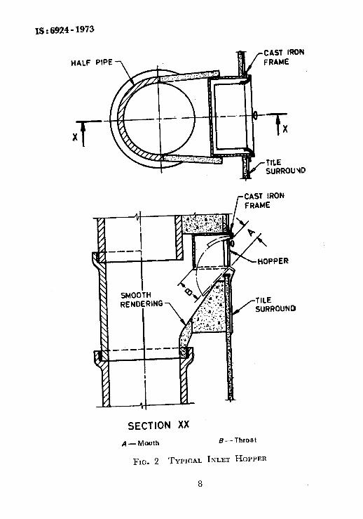
4.2 Design and Construction-Hopper shall be constructed such that there should be minimum escape of odour or any other vapour when the hopper door is kept open or closed that the inside portion of the hopper does not lodge any refuse while projecting it into the chute. The door and the frame should be fire-resistant. A typical construction of an inlet hopper is given in Fig. 2.
4.2,l Size of the Mouth and 7hfoat -The mouth shall have a maximum size of 25 cm height and 36 cm width. The throat should not be less than the size of the mouth. The diagonal of the mouth should not be larger than the chute size.
4.2.2 Height of the Hopper- The hopper should be constructed at a height of 75 cm measured from the floor level to the lower edge of the inlet opening.
4.2.3 Inner Surface -The interior of the hopper should slope towards the main chute at an angle not less than 45” to the horizontal preferably 60’ for better performance. This portion may be specially built or may be had by providing a suitable Y-connection. If built specially, the inside finish should be as smooth as possible. If provided by the use of Y-connection, it may be of asbestos cement or cast iron or cement concrete pipe.
4.2.4 Ddor, Head, Frame and Receiving Unit-These should be of mild steel, cast iron or aluminium adequately protected against corrosion. The door should be designed to be self-closing, to have a latch for closing it securely
6

h
1s : 6!YZ4 - 1973
after use and to have a rubber gasket in between the door and the frame for ensuring gas tightness and minimizing noise. The receiving plate should be fitted with two retaining side plates to prevent spillage (see Fig. 2).
4.2.5 Counterbalance of Door-The door when not in use, should fly back to its closed position and be firmly closed.
4.2.6 Hinge--The hinge shall be such as to satisfy the requirements in 4.2. It should not have sharp edges to harm the user. It should be fitted such that the door can be taken out for maintenance.
4.2.7 Handle-There should be a handle fixed properly to the door for
* operating the hopper door.
5. COLLECTION CHAMBER
JI 5.1 Location -The collection chamber shall be situated at ground level.
5.2 Capacity --If the refuse is discharged directly on the floor of the collection chamber; the capacity is designed on the quantity of refuse ex- pected from the chute between two consecutive clearings. It may be recommended to provide a minimum capacity of 0’054 m3/family or apartment per day. In the case of chutes serving small number of apart- ments, the minimum size of the collection chamber shall be 1.2 x 1.2 x 1-g m in order to facilitate providing trolley and easy cleaning of’the chamber. In case of proposals to collect refuse directly into a wheeled receptacle the capacity of the chamber should be sufficient to accommodate as many containers as would be necessary. In that case, a mild steel container suita.bly protected against corrosion or a container of any other suitable material may be used. If more than one container is in use, the minimum clearance of 15 cm between the container will be necessary. Normally the height of chute bottom above the top of the container shall be about 30 cm in order not to allow any refuse to spill on the floor of-the chamber. It will be preferable to provide a minimum head- room of 2 m for the collection chamber to facilitate easy entry into it.
,+
I
5.3 Construction-The walls and roof of the chamber shall be constructed of brick masonry or any non-combustible material. The door should be of steel or any fire resistant material. The door fitting should be properly done with the provision of rebate and reveals in the opening so as not to allow any gas or fume to escape. The inner surface of the walls, the floor and the ceiling should be plastered with cement mortar in order to provide a smooth finish. Preferably the chamber may be lined with glazed tiles for better cleaning and upkeeping. The junctions of the walls with each other and with the floor shall be smoothly rounded off to prevent lodging of dust and refuse.
7
IS:6924-1973
r CAST IRON FRAME
SECTION XX
A - Mouth B-Throat
FIG. 2 TYPICAL INLET HOPPER
8

IS : 6924 - 1973
5.4 Cleating and.Maintenance - Provision of water tap in the vicinity and drainage facility with a trapped gully shall be made in order to arrange for periodic cleaning of the chamber.
5.5 Shutter-There should be a cut-off plate or shutter at the chute bottom in order to close off the chute at the time of handling refuse in the chamber or while cleaning. The shutter shall be made of sheet iron slid- ing horizontally inside angle-iron rebates. These should be made non-corrodible with proper painting.
5.6 Lighting - Adequate artificial light should be provided in the chamber with its control switch located on the outside wall near entrance.
5.7 Access -There shall be easy access to the chamber Car the cleaners and refuse collectors. There should be a well paved pathway leading to the collxtion chamber from the nearest road in.order lo facilitate easy transport of refuse at site.
APPENDIX A ( czause 3.1 )
METHOD OF CALCULATION OF TOTAL REFUSE AND GUIDE LINES FOR DETERMINING NUMBER OF
CHUTES AND SIZE OF COLLECTION CHAMBER
Quantity of domestic refuse
Quantity of refuse - 680 g/capita/day ( average of Bomba), survey )
Density of refuse = 240 kg/m”
1000 Volume of refuse/capita/day = so x ~~0
= 2’83 litres
Assuming that a family residing in a flat would consist of an average of 6 members plus 2 servants, the average volume of refuse per family would be 2’83 x 8 = 22.64 litres/day, or say 0’027 ms/day.
Example:
To consider a multistoreyed building of 20 flats with 2 flats per floor. Refuse/flat : O-027 ma/day. (Th is is to be ascertained from the local municipality. )
a) No. of C/&es
1) To be decided on convenience to the user; and
2) To be decided on the total number of containers, if used in the collection chamber.
9

< j------------
IS:6!324-1973
Assuming that individual hopper system will be convenient to the residents, the number of chutes will be two.
To provide ftir irregularity in municipal refuse cleaning service, collection chamber be designed to accommodate 2 days refuse.
Hence, volume of refuse/clearing = O-027 ma x 20 flats x 2 days
= 1.08 ms
As there are two chutes, capacity for each collection chamber will be 1.08 __ - 0’54 m3
2 However, a chamber of size 1.2 x 1’2 x 2 m will be necessary as a minimum requirement.
b) Zf containers are to be used in the collection chamber:
Container size = 0’9 m dia x 1’3 m high of capacity of 0826 ma Volume of refuse/clearing = 0’54 ma Number of containers/chute = one
The above collection chamber size will be adequate.
/ I 10 /i
I lS:6924-1973
Assuming that individual hopper system will be convenient to the residents, the number of chutes will be two.
To provide far irregularity in municipal refuse cleaning service, collection chamber be designed to accommodate 2 days refuse.
Hence, volume of refuse/clearing = 0’027 ms x 20 flats x 2 days
= 1.08 ms
As there are two chutes, capacity for each collection chamber will be l-08 r) = 0’54 m3
H:wever, a chamber of size 1.2 x 1’2 x 2 m will be necessary as a minimum requirement.
b) If containers are to be used in the collection chamber:
Container size = 0’9 m dia x 1.3 m high of capacity of O-826 ms Volume of refuse/clearing = 0.54 ma Number of containers/chute = one
The above collection chamber size will be adequate.
10


![Dnevni avaz [broj 6924 djelimičan, 18.11.2014]](https://img.pdfslide.net/doc/110x75/577cc3471a28aba711958045/dnevni-avaz-broj-6924-djelimican-18112014.jpg)