Embed Size (px)
Citation preview
1
IS-1
Interoperability Switch
Manual Revision: 2018-01-19
Covers PCB Revisions: B
2
TABLE OF CONTENTS
Specifications 3
General Information 4
Hardware Installation 5
Hardware Alignment 6
Dip-Switch Settings 6
Controls & Indicators 7
Operation 8
IS-1 Option C 9
Theory of Operation 10
Technical Notes 11
Contact Information 11
3
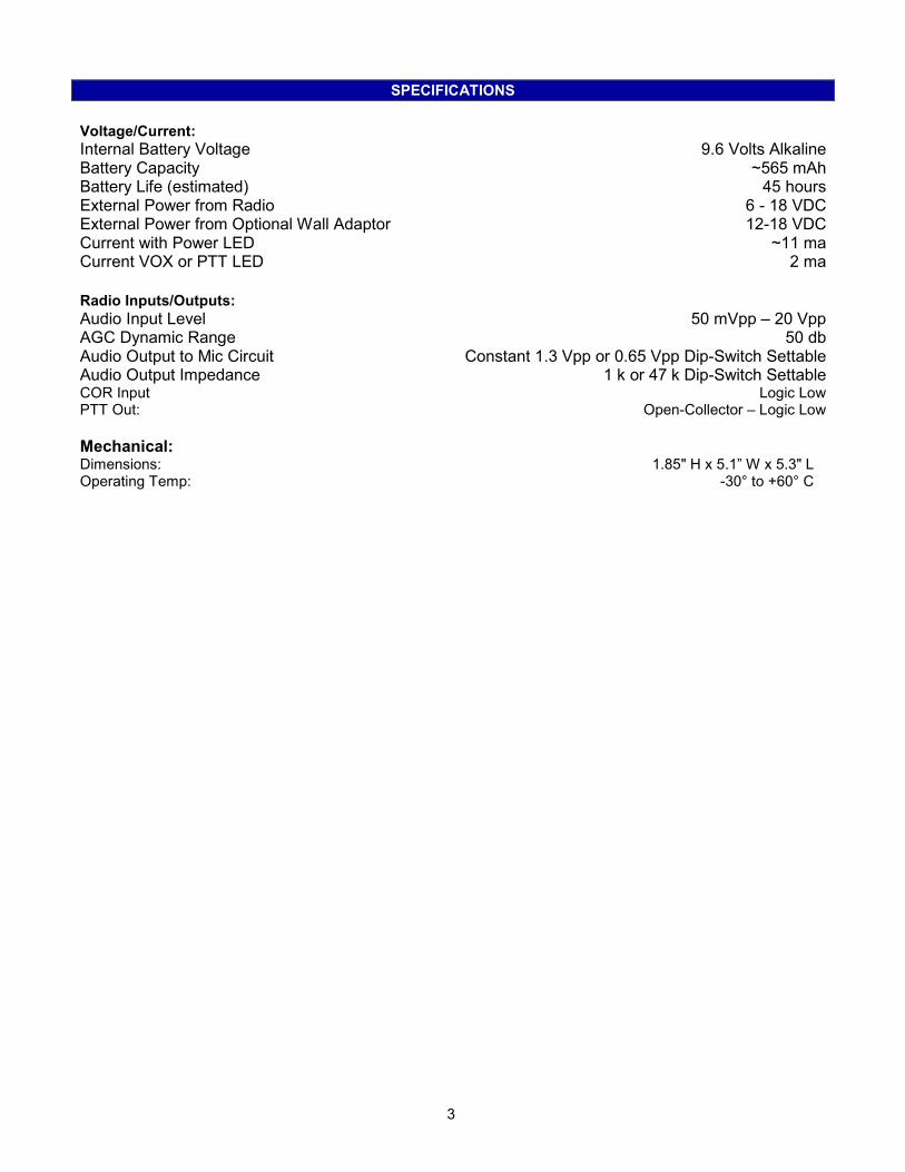
SPECIFICATIONS
Voltage/Current:
Internal Battery Voltage 9.6 Volts Alkaline Battery Capacity ~565 mAh Battery Life (estimated) 45 hours External Power from Radio 6 - 18 VDC External Power from Optional Wall Adaptor 12-18 VDC Current with Power LED ~11 ma Current VOX or PTT LED 2 ma
Radio Inputs/Outputs:
Audio Input Level 50 mVpp – 20 Vpp AGC Dynamic Range 50 db Audio Output to Mic Circuit Constant 1.3 Vpp or 0.65 Vpp Dip-Switch Settable Audio Output Impedance 1 k or 47 k Dip-Switch Settable COR Input Logic Low PTT Out: Open-Collector – Logic Low
Mechanical: Dimensions: 1.85" H x 5.1” W x 5.3" L Operating Temp: -30° to +60° C

4
GENERAL INFORMATION
The IS-1 is designed to permit interoperability between two radios of virtually any type. It can be used as a cross band repeater between a VHF and a UHF radio. It can allow interoperation between a Military HF SSB radio and an APCO 25 radio or between a MotoTRBO radio and a Kenwood NEXEDGE radio. It can be used between mobile and portable radios. It may be battery operated for up to about 50 hours when using two portable radios or may use an optional wall charger. When using mobile radios it can derive its power from the radio. The IS-1 takes the receive audio from one radio “A” and feeds it into the opposite radio “B’s” microphone circuit. When using portables the receive audio from radio ”A” is detected by the IS-1’s VOX circuit keying radio “B” which passes the above mentioned audio to radio “B”. When using mobile radios, the VOX is not used and instead the IS-1 converts the COR from radio “A” to a push to talk signal keying radio “B”. There is a monitor output jack that can be used for recording or monitoring audio with an earphone or speaker amplifier. The IS-1 Option C is an optional DTMF, 5-Tone, 2-Tone or Pulse Tone decoder to activate and deactivate the unit from field radios using the keypad on the radio or an ANI sequence on a dedicated channel. The decoder will transpond once after activation and twice after deactivation. The IS-1 Option D is an option Morse Code identification option for in-band use.
5
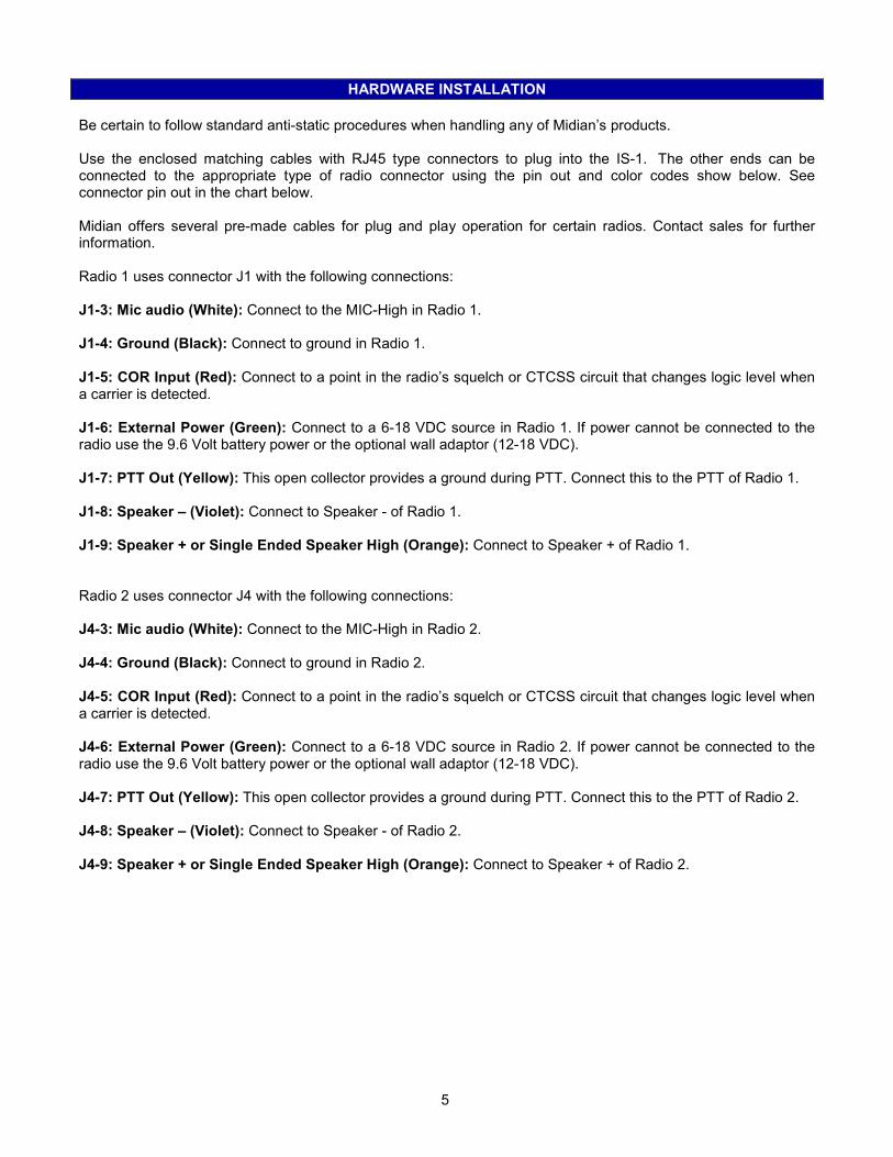
HARDWARE INSTALLATION
Be certain to follow standard anti-static procedures when handling any of Midian’s products. Use the enclosed matching cables with RJ45 type connectors to plug into the IS-1. The other ends can be connected to the appropriate type of radio connector using the pin out and color codes show below. See connector pin out in the chart below. Midian offers several pre-made cables for plug and play operation for certain radios. Contact sales for further information. Radio 1 uses connector J1 with the following connections: J1-3: Mic audio (White): Connect to the MIC-High in Radio 1. J1-4: Ground (Black): Connect to ground in Radio 1. J1-5: COR Input (Red): Connect to a point in the radio’s squelch or CTCSS circuit that changes logic level when a carrier is detected. J1-6: External Power (Green): Connect to a 6-18 VDC source in Radio 1. If power cannot be connected to the radio use the 9.6 Volt battery power or the optional wall adaptor (12-18 VDC). J1-7: PTT Out (Yellow): This open collector provides a ground during PTT. Connect this to the PTT of Radio 1. J1-8: Speaker – (Violet): Connect to Speaker - of Radio 1. J1-9: Speaker + or Single Ended Speaker High (Orange): Connect to Speaker + of Radio 1. Radio 2 uses connector J4 with the following connections: J4-3: Mic audio (White): Connect to the MIC-High in Radio 2. J4-4: Ground (Black): Connect to ground in Radio 2. J4-5: COR Input (Red): Connect to a point in the radio’s squelch or CTCSS circuit that changes logic level when a carrier is detected. J4-6: External Power (Green): Connect to a 6-18 VDC source in Radio 2. If power cannot be connected to the radio use the 9.6 Volt battery power or the optional wall adaptor (12-18 VDC). J4-7: PTT Out (Yellow): This open collector provides a ground during PTT. Connect this to the PTT of Radio 2. J4-8: Speaker – (Violet): Connect to Speaker - of Radio 2. J4-9: Speaker + or Single Ended Speaker High (Orange): Connect to Speaker + of Radio 2.
6
HARDWARE ALIGNMENT
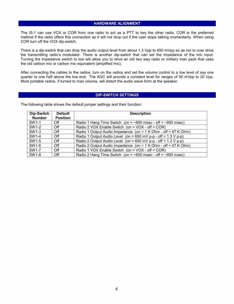
The IS-1 can use VOX or COR from one radio to act as a PTT to key the other radio. COR is the preferred method if the radio offers this connection as it will not drop out if the user stops talking momentarily. When using COR turn off the VOX dip-switch. There is a dip-switch that can drop the audio output level from about 1.3 Vpp to 650 mVpp so as not to over drive the transmitting radio’s modulator. There is another dip-switch that can set the impedance of the mic input. Turning the impedance switch to low will allow you to drive an old two way radio or military man pack that uses the old carbon mic or carbon mic equivalent (amplified mic). After connecting the cables to the radios, turn on the radios and set the volume control to a low level of say one quarter to one half above the low end. The AGC will provide a constant level for ranges of 50 mVpp to 20 Vpp. Most portable radios, if turned to max volume, will distort the audio wave form at the speaker.
DIP-SWITCH SETTINGS
The following table shows the default jumper settings and their function:
Dip-Switch Number
Default Position
Description
SW1-1 Off Radio 1 Hang Time Switch (on = ~600 msec - off = ~900 msec)
SW1-2 Off Radio 2 VOX Enable Switch (on = VOX - off = COR)
SW1-3 Off Radio 1 Output Audio Impedance (on = 1 K Ohm - off = 47 K Ohm)
SW1-4 Off Radio 1 Output Audio Level (on = 650 mV p-p - off = 1.3 V p-p)
SW1-5 Off Radio 2 Output Audio Level (on = 650 mV p-p - off = 1.3 V p-p)
SW1-6 Off Radio 2 Output Audio Impedance (on = 1 K Ohm - off = 47 K Ohm)
SW1-7 Off Radio 1 VOX Enable Switch (on = VOX - off = COR)
SW1-8 Off Radio 2 Hang Time Switch (on = ~600 msec - off = ~900 msec)
7
CONTROLS & INDICATORS
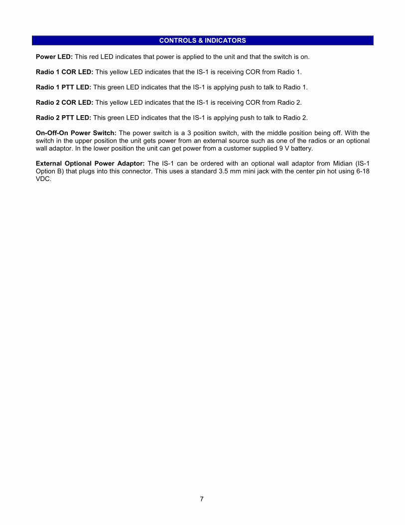
Power LED: This red LED indicates that power is applied to the unit and that the switch is on. Radio 1 COR LED: This yellow LED indicates that the IS-1 is receiving COR from Radio 1. Radio 1 PTT LED: This green LED indicates that the IS-1 is applying push to talk to Radio 1. Radio 2 COR LED: This yellow LED indicates that the IS-1 is receiving COR from Radio 2. Radio 2 PTT LED: This green LED indicates that the IS-1 is applying push to talk to Radio 2. On-Off-On Power Switch: The power switch is a 3 position switch, with the middle position being off. With the switch in the upper position the unit gets power from an external source such as one of the radios or an optional wall adaptor. In the lower position the unit can get power from a customer supplied 9 V battery. External Optional Power Adaptor: The IS-1 can be ordered with an optional wall adaptor from Midian (IS-1 Option B) that plugs into this connector. This uses a standard 3.5 mm mini jack with the center pin hot using 6-18 VDC.
8
OPERATION
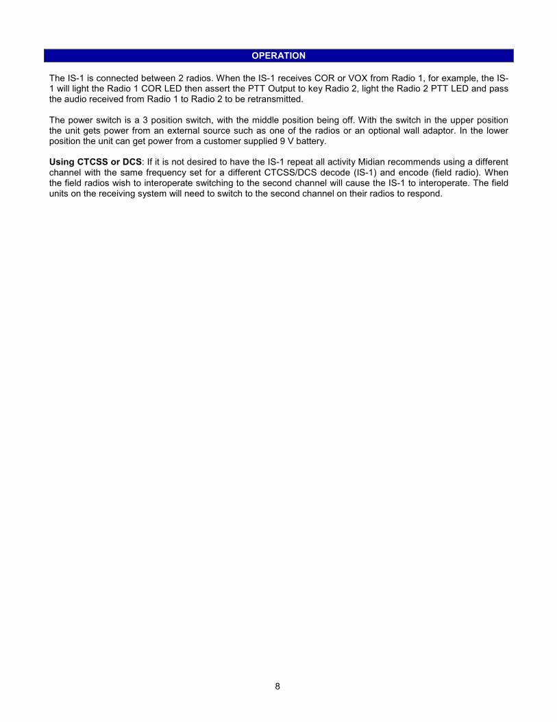
The IS-1 is connected between 2 radios. When the IS-1 receives COR or VOX from Radio 1, for example, the IS-1 will light the Radio 1 COR LED then assert the PTT Output to key Radio 2, light the Radio 2 PTT LED and pass the audio received from Radio 1 to Radio 2 to be retransmitted. The power switch is a 3 position switch, with the middle position being off. With the switch in the upper position the unit gets power from an external source such as one of the radios or an optional wall adaptor. In the lower position the unit can get power from a customer supplied 9 V battery. Using CTCSS or DCS: If it is not desired to have the IS-1 repeat all activity Midian recommends using a different channel with the same frequency set for a different CTCSS/DCS decode (IS-1) and encode (field radio). When the field radios wish to interoperate switching to the second channel will cause the IS-1 to interoperate. The field units on the receiving system will need to switch to the second channel on their radios to respond.
9
IS-1 OPTION C: ENABLE/DISABLE OPTION
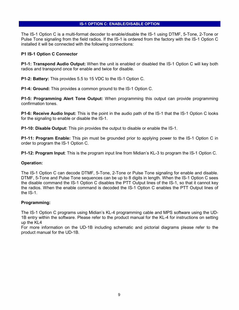
The IS-1 Option C is a multi-format decoder to enable/disable the IS-1 using DTMF, 5-Tone, 2-Tone or Pulse Tone signaling from the field radios. If the IS-1 is ordered from the factory with the IS-1 Option C installed it will be connected with the following connections: P1 IS-1 Option C Connector P1-1: Transpond Audio Output: When the unit is enabled or disabled the IS-1 Option C will key both radios and transpond once for enable and twice for disable. P1-2: Battery: This provides 5.5 to 15 VDC to the IS-1 Option C. P1-4: Ground: This provides a common ground to the IS-1 Option C. P1-5: Programming Alert Tone Output: When programming this output can provide programming confirmation tones. P1-6: Receive Audio Input: This is the point in the audio path of the IS-1 that the IS-1 Option C looks for the signaling to enable or disable the IS-1. P1-10: Disable Output: This pin provides the output to disable or enable the IS-1. P1-11: Program Enable: This pin must be grounded prior to applying power to the IS-1 Option C in order to program the IS-1 Option C. P1-12: Program Input: This is the program input line from Midian’s KL-3 to program the IS-1 Option C. Operation: The IS-1 Option C can decode DTMF, 5-Tone, 2-Tone or Pulse Tone signaling for enable and disable. DTMF, 5-Tone and Pulse Tone sequences can be up to 8 digits in length. When the IS-1 Option C sees the disable command the IS-1 Option C disables the PTT Output lines of the IS-1, so that it cannot key the radios. When the enable command is decoded the IS-1 Option C enables the PTT Output lines of the IS-1. Programming: The IS-1 Option C programs using Midian’s KL-4 programming cable and MPS software using the UD-1B entry within the software. Please refer to the product manual for the KL-4 for instructions on setting up the KL4 For more information on the UD-1B including schematic and pictorial diagrams please refer to the product manual for the UD-1B.
10
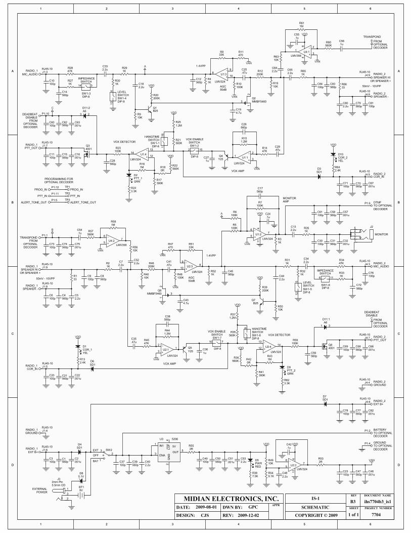
THEORY OF OPERATION
This discussion pertains to the part numbers on the top section of the schematic drawing. Both audio path circuits (A&B) are identical with the exception of the part numbers and pin out to the respective connectors. Single ended audio or +/- speaker audio from radio “A” is fed into pin 9 or pins 8&9 into the AGC circuit U1:3. The AGC has a 50 db dynamic range from 50 mVpp to 20 Vpp. It will provide a constant 1.3 Vpp output across R3. Audio is fed out, to the opposite radio’s mic circuit, through R28 where it may be attenuated in half by R29 if the level switch is closed. The audio is presented to the opposite radio on J1-3 via R-27 or R-26. For high impedance radios leave the impedance switch open. For low impedance radios close the switch. When working with radios that do not have COR available turn on the VOX enable switch. This takes audio from the VOX amp U1:1 triggering Q4 discharging C18 causing comparator U1:4 to place its output high turning on the PTT transistor Q3 and the green PTT LED D2. PTT transistor Q32 will then go low keying the radio. When voice drops out Q4 will start to charge back up eventually exceeding the comparators threshold turning off the PTT. The hang time can be reduced from 900 msec to 600 msec by closing the Hang Time dip switched thus shorting out R24. A logic low on the COR input on connector J4-5 can also discharge C18 via diode D6 turning on the PTT comparator. When using the COR input, turn off the VOX enable switch. The IS 1 employs a 5 volt regulator to power the circuitry. A center off toggle switch allows you to select either internal battery power or external power from the radio or an optional 12-18 volt wall charger. The charger only needs to be capable of 50 mA or less. The charger connector has an internal switch to disconnect the batteries ground side so it cannot be accidently charged. The center off switch also precludes accidental charging of the battery. Alkaline batteries are cheap and readily available and have a 565 mAh capacity. Lithium could also be used and have a higher mAh ratting. If the IS-1 Option C is used it disables the PTT by grounding the base of Q3 via D3:2 during disable mode. Transpond from the IS-1 Option C is inserted at P1-1 and fed through op-amp U4:1 into the AGC audio path. During transpond the disable lead from the decoder is momentarily blocked, with a jumper on the decoder, to allow the PTT to key the radios during transpond.

11
TECHNICAL NOTES
VOX Detect: When using VOX detect go ahead beeps must be disabled in the connected radios.
MIDIAN CONTACT INFORMATION
Midian Electronics Inc. 2030 N. Forbes Blvd. #101 Tucson, Arizona 85745 USA Orders: 1-800-MIDIANS Phone: 520-884-7981 Fax: 520-884-0422 E-mail: [email protected] Web: www.midians.com

- This page intentionally left blank -
1
1
2
2
3
3
4
4
5
5
6
6
D D
C C
B B
A A
ihs7704b3_is1
CJS
2009-08-01 GPC
2009-12-02
B3
1 of 1 7704
IS-1MIDIAN ELECTRONICS, INC.
DATE:
DESIGN:
DWN BY:
REV:
APPRSCHEMATIC
COPYRIGHT © 2009
REV
SHEET PROJECT NUMBER
DOCUMENT NAME
2.2uC13
560pC31
LMV324
-
+
6
57
411
U1:2
SD1D4
VAN
100KR5
100KR6
100KR7
560pC17
1KR3
1KR26
9VBT1
23 SW2
2.2uC40
560pC39 560p
C502.2uC53
5206
IN11
ENA3
GND
2LVF
4
OUT5
U3
PWRRED
D5
7.5KR38
9.1KR54
10KR49
2.2u
C48
LMV324
-
+
6
57
411
U2:2
560pC47
VAN
VDD
1MR43
0RR42
560KR36
390KR41
47KR45
1u
C36 4001Q8
Y25
Q5
100KR48
LMV324
-
+
2
31
U2:1
VAN
100KR59
.47uC35
LMV324
-
+
13
1214
U2:4
560pC59
PTT_2GRN
D9
3.3KR62
VDD
2.4KR13
SD1
D6
VDD
COR_1YEL
D1
2.2uC34
LMV324
-
+
9
108
U2:3
VAN
1KR52
2.2uC7
.47uC41
33KR51
SD1D7
B25Q7
2.2uC44
10KR50
VDD
1MR16
0RR18
560KR22
390KR17
47KR14
1uC27
4001Q3
Y25Q4
LMV324
-
+
2
31
U1:1
VAN
100KR23
.47uC29
LMV324
-
+
13
1214
U1:4
560pC28
PTT_1GRN
D2
3.3KR24
2.4KR64
SD1D3
VDD
470R11
100KR10
2.2uC33
560pC14
LMV324
-
+
9
108
U1:3
VAN
1KR4
2.2uC65
.47uC25
33KR8
B25Q1
2.2uC18
10KR9
VDD
A
MONITOR321
45 J2
VDD
.1uC42
VDD
.1uC24
RJ45-10
MIC_AUDIORADIO_2J4:3
DIP-8
SW1-2
2 15
DIP-8SW1-4
413
DIP-8SW1-5
512
DIP-8
SW1-7
710
DIP-8SW1-3
314
47KR28
560p
C72
47KR34
DIP-8SW1-6
6 11
RJ45-10
PTT_OUTRADIO_2J4:7
RJ45-10
EXT B+RADIO_2J4:6
RJ45-10
GROUNDRADIO_2J4:4
RJ45-10
GROUNDRADIO_1 J1:4
RJ45-10
EXT B+
RADIO_1 J1:6
RJ45-10
COR_INRADIO_1 J1:5
RJ45-10
SPEAKER HIRADIO_1 J1:9
RJ45-10
SPEAKER -RADIO_1 J1:8
33R1
2.2uC5
DIP-8SW1-8
89
VDD
DIP-8SW1-1
116
RJ45-10
MIC_AUDIO
RADIO_1 J1:3 RJ45-10
SPEAKER HI
RADIO_2J4:9
RJ45-10
SPEAKER -RADIO_2J4:8
33R66
2.2uC80
RJ45-10
PTT_OUTRADIO_1 J1:7
RJ45-10
COR_INRADIO_2J4:5
1KR33
1KR27
VDD
VDD
A
200KR12
200KR46
1KR30
1KR29
1KR32
1KR31
2RR55
EXT
OFF
BAT
EXTERNALPOWER
560pC77
560pC68
560pC70
560pC83
560pC15
560pC8
560pC4
560pC21
560pC1
560pC79
OR SPEAKER +
OR SPEAKER +
50mV - 10VPP
50mV - 10VPP
VOX AMP
VOX AMP
AGC50dB
AGC50dB
VAN
VAN
1.4VPP
1.4VPP
IMPEDANCESWITCH
IMPEDANCESWITCH
SWITCHLEVEL
SWITCHLEVEL
HANGTIMESWITCH
HANGTIMESWITCH
SWITCH
200KR39
200KR20
MONITORAMP
4.7uC19
4.7uC43
470R47
MMBF5460
2
3
1
Q2
MMBF5460
2
3
1
Q6
5V
1
VOX DETECTOR
VOX DETECTOR
5.1VD8
2
1
3
J32mm Pin5.5mm OD
560KR21
1.2MR37
560KR35
1.2MR44
1.2MR15
1.2M
R25
A61 3
D11:1
A623
D11:2
C
C
560pC26
560pC38
100pC69
.001uC66
.001u
C51.001uC2
100pC3
100pC37 100p
C49
100pC23
.001uC46
VOX ENABLE
SWITCHVOX ENABLE
100pC78
.001uC82
100pC76
100pC30
.001uC32
100pC71
.001uC67
100pC81
1KR65
100pC84100p
C10
100pC11
.001uC16
100pC20
.001uC22
1KR2
100pC9
100pC6
.1uC54
560KR57
2.2uC52
10KR56
1MR58
VAN
B
.1uC56
560KR60
2.2uC64
10KR63
1MR61
VAN
B
COR_2YEL
D10
TRANSPOND
DISABLEDEADBEAT
-
+
2
31
48
LMV358
U4:1
-
+
6
57
LMV358
U4:2
2RR53
560pC62
100pC60
.001uC63
FROM
DECODER
DISABLE
OPTIONAL
DEADBEAT P1:10
FROM
DECODEROPTIONAL
TRANSPONDP1:1
GROUNDTO OPTIONAL
DECODER
P1:4
BATTERYTO OPTIONALDECODER
P1:2
PROG_INP1:12
PTT_INP1:11
ALERT_TONE_OUTP1:5
PROG_INTP1
PTT_INTP2
ALERT_TONE_OUTTP3
DTMFTO OPTIONAL
DECODER
P1:6
560pC74
100pC73
.001uC75
VDD
.1uC55
FROM
DECODER
FROM
OPTIONAL DECODER
DECODEROPTIONAL
OPTIONAL
560pC45
560pC12
10KR19
10KR40
PROGRAMMING FOR
560pC58
100pC61
.001uC57
2 3 4 5 61
1 2 3 4 5 6
A
B
C
DD
C
B
A

- This page intentionally left blank -


![The Land of Midian [revisited]](https://img.pdfslide.net/doc/110x75/61fc86dd8d33c02b785e34b2/the-land-of-midian-revisited.jpg)


