Embed Size (px)
Citation preview
REQUEST FOR QUOTATION FOR REPLACEMENT OF THERMAL
DATA ACQUISITION AND CONTROL SYSTEM OF 6.5M CATVAC
1
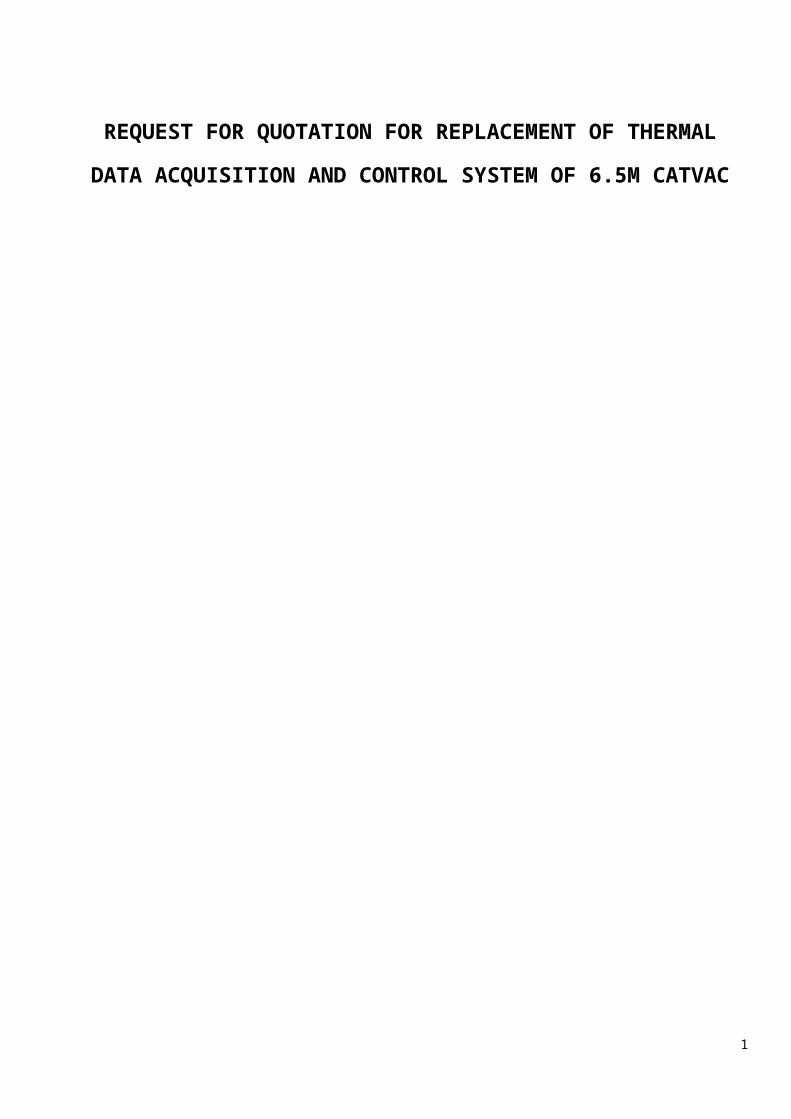
NOMENCLATURES
SL.NO01 AC/DC Alternate Current/Direct Current02 ACAD Auto-Cad03 AMSC Annual Maintenance Service Contract04 ASCII American Standard Code For Information Interchange05 BPS Bits per second.06 CATVAC Comprehensive Assembly And Test Thermovac Chamber07 CJC Cold Junction Compensation08 CMMR Common Mode Rejection Ratio09 CPU Central Processing Unit10 DAS Data Acquisition System11 DPU Data Processing Unit12 ETF Environmental Test Facility13 FC Fault Clear14 IPV6 Internet Protocol Version 615 ISAC ISRO Satellite Centre16 ISITE ISRO Satellite Integration And Testing Establishment17 ISPD ISRO Software Process Document18 LCD Liquid Crystal Display19 LSSC Large Space Simulation Chamber20 OL Over Load21 OS Operating Systems22 OT Over Temperature23 OV Over Voltage24 PACU Power And Control Unit25 PATC Programmable Automatic temperature Controller26 PF Power Supply Fault27 PID Proportional Integral Differential28 PID no. Parameter Identification number29 PRT Platinum Resistance Thermometer30 PSPU Power Signal Processing Unit31 RDBMS Relational Data Base Management Systems32 RFP Request For Proposal
2
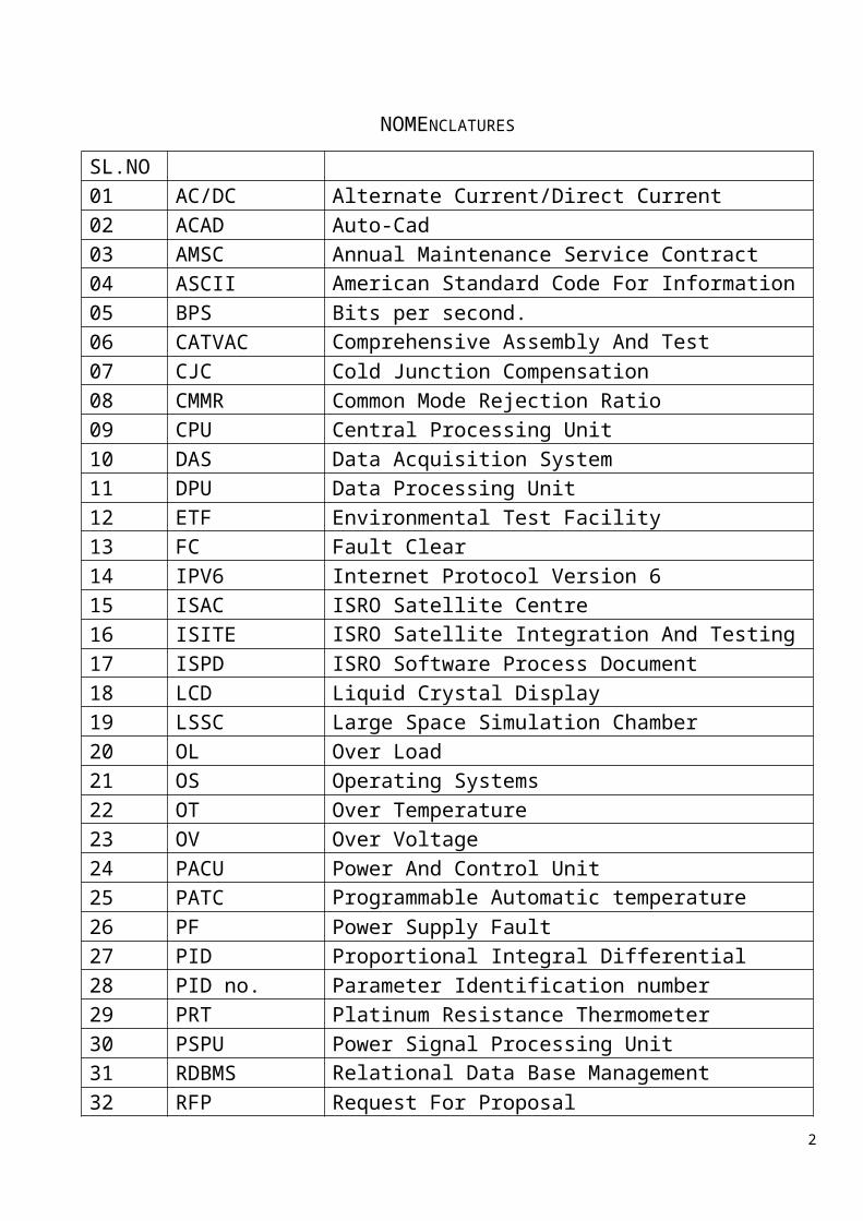
33 RFQ Request For Quotation34 RM/LM Remote Mode/Local Mode35 SCADA Supervisory Control And Data Acquisition36 SGCO Spacecraft Ground Checkout37 SMPS Switching Mode Power Supplies38 SWG/AWG Standard Wire Gauge/American Wire Gauge39 T/C Thermocouple40 TCP/IP Transmit ion Control Protocol/Internet Protocol41 TDACS Thermal Data Acquisition And Control System42 TSG Thermal System Group43 TSPU Temperature Signal Processing Unit44 TVAC Thermal Vacuum Chamber45 USB Universal Serial Board
3
CONTENTS
Sl.No Headings/Sub Headings Page
Introduction 5
1.Scope Of Work
6
2.Supplier’s Experience & Offer Evaluation Approach
6
3.Over All System Configuration
7
4.System Design
8
5.TSPU
8
6.PSPU
9
7.SMPS
10
8.DPU- General
12
9.DPU Software
14
10.Security And Access Control
29
11.Networking/ All The Hardware And Accessories Involved Including Computer
29
12.Electrical Cabling
29
13.Environment
30
14.Design Review
30
15.Pre-Delivery inspection and testing at vendor site
30
16.Installation, commissioning & acceptance testing at ISAC/ISRO
31
4
17.Training
32
18.Deliverable Documents
32
19.Tentative Delivery Schedule
33
20.Warranty
33
21.Instruction To Vendors For Submitting Offer
33
Format For Commercial Bid 35
Annexure A: Details of thermal simulation / thermal instrumentation on spacecraft/ electronics packages for conducting thermal tests
38
Annexure-B: Specifications For DPU Hardware 39
Annexure C: DPU Block Diagram 47
Annexure D: Floor Area For TDACS 48
5
INTRODUCTION
ISAC is the lead center of ISRO for the development, manufacturing, and testing of satellite in India. Several test facilities have been established to carry out the qualification / acceptance tests on satellite hardware /sub-assemblies. One of the facility, called, 6.5 meter diameter Thermovac chamber (commonly known as “CATVAC”) is available at its ISITE Facility”, Marathahalli campus in Bangalore- 560037, Karnataka, India. It is equipped with a TDACS for thermal simulation on satellite and its subsystems / sub-assemblies to conduct following tests:
Thermovac performance test Thermal balance tests
Details of thermal simulation / thermal instrumentation for these tests are given in Annexure-A.
The TDACS of this facility was procured in 2004 and now, it is planned to replace the existing computer based data acquisition and control system, with latest technology based TDACS and augmentation with more thermal monitoring and control equipments.
The major functions of the proposed “Thermal Data Acquisition and Control System” is
To monitor temperature using different type of temperature sensors like T type Thermocouple (T/C), Platinum Resistance Thermometer (PRT) and Thermistors.
Acquisition of Data- satellite telemetry from Satellite Ground Checkout (SGCO) computer system.
Acquisition of Data - chamber parameters from CATVAC Server through Ethernet.
To monitor power supplies / control parameters
Pseudo channel processing.
Control of predefined voltage, power, temperature parameter/ profile.
Temperature / temperature profile control using PID based auto temperature controller with any of the monitored parameter as feedback for control purpose.
Data processing, acquiring, storing, real time as well historical data display in specified formats, stored data retrieval, documentation etc.
6
On behalf of ISRO, ISAC invites the proposal from reputed and experienced vendors for “TDACS” OF 6.5M CATVAC as per the following requirements / specifications provided in the subsequent section of this RFQ.
1. Scope Of Work
Design, fabricate, pre-delivery acceptance, performance demonstration, supply, installation, commissioning and final acceptance performance testing as per specifications of total system at ISITE, ISAC, Marathahalli campus, Bangalore- 560037, Karnataka, India.
2. Supplier’s Experience & Offer Evaluation Approach
i) The vendor shall be a manufacturer or authorized integrator of the similar type of system.
ii) In case of system integrator, vendor shall hold full responsibility of execution of this system completely in all aspects and for the further maintenance. Valid authorization letters from the original manufacturer shall accompany the quotation. This shall also include the warranty support.
iii) Vendor shall provide assurance for supply of spares of the system for the minimum period of 10 years from the date of commissioning.
iv) Vendor shall have developed, installed, commissioned and managed similar type of system having value of similar scale in the last 5 years. Copy of the purchase order, work order and completion certificate of the same shall accompany the quotation.
v) Vendor shall submit list of customers with contact name, address, phone details etc. to whom similar type of system has been supplied.
vi) The vendor shall provide detailed point by point compliance of the quoted item with respect to RFQ specifications. Otherwise offer will not be considered.
vii) In case of any deviation from specification or any improvement in parameters/facility features vendor shall clearly provide justification of the same
viii) Vendor shall submit, along with offer, the necessary technical details and all relevant documents to substantiate their experiences, test and evaluation capabilities along with associated infrastructure details.
ix) Offers received will be evaluated based on merit, content of each offer, experience of vendor, and heritage of facility.
x) Vendor/s may be asked to make a detailed presentation on their offer to the expert committee of ISAC/ISRO at ISAC/ISRO as a part of vendor evaluation
7
process. Vendor shall provide confirmation for this detailed technical presentation in the technical offer / quotation.
xi) Offers without the above information or offers with incomplete / inaccurate / false information will be rejected.
xii) ISAC/ ISRO reserve the right to modify and finalize the configuration after studying the proposals from vendor.
xiii) Vendor can visit existing TDACS at ISAC/ISRO before submitting the quotation.
3. Over all System Configuration
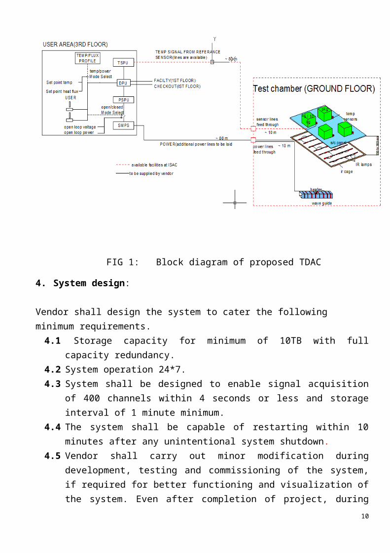
A typical block diagram of the system is shown in Fig-1. System shall be configured into four major subsystems.(i) TSPU
(ii) PSPU
(iii) SMPS
(iv) DPU
FIG 1: Block diagram of proposed TDAC
8
4. System design:
Vendor shall design the system to cater the following minimum requirements.4.1 Storage capacity for minimum of 10TB with full capacity redundancy. 4.2 System operation 24*7. 4.3 System shall be designed to enable signal acquisition of 400 channels within 4
seconds or less and storage interval of 1 minute minimum. 4.4 The system shall be capable of restarting within 10 minutes after any unintentional
system shutdown. 4.5 Vendor shall carry out minor modification during development, testing and
commissioning of the system, if required for better functioning and visualization of the system. Even after completion of project, during warranty period, whenever required, vendor shall make minor modification.
5 TSPU
TSPUs shall acquire the output signals of three types of temperature sensors, namely, T-type T/C, PRT and thermistors and process them into engineering unit.
5.1 Number of TSPU units : Two independent units
5.2 Type of temperature sensors to be processed:
5.2.1 T/C: T-type
a. Number of Channels per TSPU: 256 nos. b. Each T/C input card shall have 8/16/32 channelsc. Temperature measurement range: -200 ºC to +200 ºCd. Resolution of measurement: better than 0.1 ºC. e. Accuracy of measurement: Better than ±0.5 ºC above -40 ºC and better than
±1 ºC below – 40 ºC, including CJC and engineering unit conversion but excluding thermocouple error.
f. The measurement accuracy and stability shall not change beyond specification for T/C after including the shielded extension wires from chamber wall exposed to noise of frequency 50 Hz and its harmonics, 10m of shielded & 10m of unshielded T/C wires exposed to noise of frequency 10MHz to 40GHz.
5.2.2 PRT
a. Number of Channels per TSPU: 16 nos.b. PRT Resistance at 0 ºC: 100 Ohms, 300 Ohms, 1000 Ohms, 2000 Ohms
(user selectable).9
c. Temperature range: -200 ºC to +200 ºCd. Resolution: Better than 0.1 ºC. e. Accuracy: Better than ±0.5 ºC excluding PRT error
5.2.3 Thermistors:
a. Number of Channels per TSPU: 48 nos.b. Resistance at 25ºC: 5K Ohms and 10K Ohms (user selectable).c. Number of Channels: 48 nos.d. Temperature range: -80 ºC to +150 ºCe. Resolution of measurement: better than 0.1 ºC. f. Accuracy of measurement: better than ±0.5 ºC excluding thermistors error.
5.3 Channel repeatability and channel to channel variation shall be within 0.2 ºC for all temperature sensors of same type.
5.4 Signal conditioning shall be designed in such a way that it shall be able to accept 2 wires for T-type Thermocouple, 4 wires for PRT and 2 wires for thermistors.
5.5 CMMR shall be greater than 100 dB.5.6 Sampling and scan rate shall be designed to enable signal acquisition of 400
channels within 4 seconds or less.5.7 Scan interval shall be programmable in steps of 1 second.5.8 The channels for scanning shall be programmable with channels skip option.5.9 Each signal conditioning card shall have a built-in auto calibration facility.5.10 Each signal conditioning card shall have built-in open thermocouple detection
circuit. 5.11 There shall be provision for screw mount type terminal in each TSPU to interface
256 channels of Teflon insulated T/C extension wire of 26 SWG, 48 channels of thermistors extension lines of 22 SWG, and 16 Channel of PRT extension lines of 22SWG.
5.12 The communication interface between TSPU, PSPU, DPU shall be Ethernet based 10/100/1000 bps.
5.13 The CJC data shall be available to main computer of DPU.5.14 All software interfaces including device drivers and I/O libraries between TSPU
and DPU are to be supplied.
6. PSPU
PSPU is an interface unit in between SMPS and DPU. It processes and communicates the control signal from DPU to SMPS and all the monitoring signals of SMPS to DPU.
10
6.1 There shall be two independent units of PSPU. 6.2 Each PSPU shall be capable of processing 256 channels.6.3 Each PSPU shall have two CPU for hot redundancy. 6.4 Health monitoring signals of the PSPU’S mainframe shall be available to the
main computer of DPU.6.5 Provisions for simultaneous opening/closing of output relay of all/selected power
supplies shall be provided.6.6 Each PSPU/TDACS shall be capable of operating 256 numbers of SMPS in
following modes Open loop voltage and power control Closed loop Temperature Control using PID controller with user
selectable process variable from either TSPU, SGCO and CATVAC temperature parameters.
6.6 SMPS shall be possible to switch from remote to local mode and local to remote mode from all workstations.
7. SMPS
7.1 Number of Power Supplies: 176 numbers.
7.2 Power Output Rating: 128 nos. of 0-60V / 0-12A
48 nos of 0-60V / 0-25A .
7.3 Continuously variable output voltage from 0 to 60 V by means of front panel multi turn pot/ rotary pulse type knob in manual mode and using digital control input in remote mode.
7.4 Drift/stability: < 0.25% of set voltage over 24 hours.
7.5 Load regulation Voltage: < 0.2%
7.6 Line regulation Voltage: < 0.2%
7.7 Ripple: < 100mV (0 to 30V), < 200mV (30V to 60V)
7.8 DC Efficiency: Better than 85%
7.9 Protection features
a. Input through a toggle switch with protection fuse.b. Startup current: must meet startup current of the load. Cold start load
shall less than 2 ohms.
11
c. Crowbar Protection for output over-voltage: Trip voltage adjustable from 0 V (crowbar setting) to maximum output remotely from workstations and locally from front panel.
d. Overload: Adjustable from 0 to maximum output load remotely from workstations and locally from front panel.
e. Over temperature: Output shall automatically trip to zero on over temperature when heat sink/transformer temperature or any specific point as per the design exceeds safe temperature.
f. The power supply should go into CC mode when overloaded. When the duration of overload is more than fixed duration which is pre definable from 0.5 seconds to 10 seconds the power supply should trip with over load indication.
g. Power failure protection: If AC power input to power supplies goes off its output voltage will become zero and when AC power is restored the output relay shall go off.
h. Line filter at input of each power supply shall be provided.
7.10 SMPS shall be of reputed makes- LAMBDA /SORENSEN / AMETEK or from any reputed international vendor.
7.11 Indications
a. Input supplyb. Fault indication for OV, OL and OT.c. Output relay ON/OFF statusd. Operating mode- LM or RM
7.12 Digital meter on front panel for output voltage measurement with 1V resolution
and current with 0.25A resolution or better .
7.13 Power supply output ON/OFF and RESET switch shall be available remotely and locally from front panel.
7.14 Power supply remote Control should be 12 bit or better
7.15 Monitoring signals Power supply status: Over voltage, Over Current, Over Temperature,
Fault, Relay ON/OFF and Remote/Local. Output Voltage: 12 bit or better read back signal proportional to output
voltage. Accuracy better than 0.5% of reading.
12
Output Current: 12 bit or better read back signal proportional to output current. Accuracy better than 1.0% of reading.
Active Power: Shall be better than 0.98 at nominal input and full load condition and 0.9 at 25% of the full load.
7.16 All monitoring signals shall be available at main computer.
7.17 Control modes of each SMPS:
Open loop - Power/voltage control.- Voltage/power Profile mode
Closed loop
- Temperature control mode using PID controller algorithm. The PV shall have redundancy for closed loop temperature control. The PV can be from SGCO or TSPU or facility.
- The PID Temperature Control accuracy of +/- 0.5 Deg C. The PID controller algorithms shall have proven heritage. Vendor has to demonstrate PID controller performance in auto and manual tuning mode under thermo vacuum test conditions before integrating it to the system.(ref :fig 1)
- Predefined Time VS Temperature profile7.18 Communication/control interfaces shall be mainly RS232/485.Additional LAN
interface for selected power supplies shall be provided.7.19 Forced air flow shall be from front to rear. No ventilation holes at the top or
Bottom of the chassis; Variable fan speed is required.7.20 Dimension : Width: ≈450mm, Height: ≈44mm, Depth: ≈500mm7.21 Weight : less than 15kg
8. DPU- General
8.1 It shall acquire, store, display all the test data parameters - historical as well in real time.
8.2 It shall have modules for data analysis, data retrieval, report generation etc.8.3 It shall communicate with TSPU, PACU, SGCO computer server & facility
server through Ethernet
13
8.4 The SCADA application software shall be compatible to the DPU, TSPU, PACU hardware, SGCO/Facility Gateway etc. The application software shall have standard protocol to connect DPU, TSPU, PACU and Gateway.
8.5 The DPU hardware shall consist of rack and rack mountable Main and Backup servers, Web Server, External Storage, Backup storage devices, Network devices, Work stations, computer peripherals and wall mountable LCD display screens etc.
8.6 All the servers shall have common hardware configuration and shall be interchangeable.
8.7 System image of each completely configured server shall be available on bootable media to ascertain bare metal recovery. These system images will be useful in system recovery to a fully operational configuration after disk crash or corruption.
8.8 The following are the minimum requirement of computers and its peripherals:a. Main Server: One Numberb. Redundant Server: One Numberc. Web server: one numberd. Work stations: 10 No’s e. Data Backup storage device – 2 No’s f. Black & White Printers( A4 size, duplex printing facility): two
Numbersg. Color laser Printer ( A4 size, duplex printing facility): one Number h. Scanners: One Number i. Wall mountable Display screens: 3 nos.j. External Storage – 3 Numbers k. Switch: L2, L2+ as required
8.9 Servers, workstations, external storage etc. shall have configuration as specified in annexure B or better to meet the application software requirement.
8.10 There shall not have single point failure.8.11 Web server shall be able to handle at least 25 simultaneous client connections.8.12 Desktops shall not to be quoted in place of Workstations 8.13 Latest version of MS- Office (For test data documentation)– License-
2Nos,ACAD (for animation and test data documentation) – License – 2 No’s shall be provided.
14
9 DPU Software
ISPD Standards and guidelines shall be followed for Software development. These standards/guidelines are available with ISAC/ISRO and will be provided to supplier by ISAC/ISRO.
Source code written specific to ISAC shall be provided as deliverable item to ISAC.
9.1 Support PlatformServer: Red Hat Enterprise(version 7.0 or above) Linux Client: Linux (version 7.0 or above) / Windows 8.1 professional version or
Higher)The vendor shall chose programming languages which support standard Internet browsers like IE, Mozilla Fire Fox, Google chrome to meet the requirements specified in this document and the languages shall take-care future upgradeability.
Vendor shall provide all required software licenses. Vendor shall provide the driver software for all printers, scanners and
any other hardware9.2Scalable configuration:
The application software shall be configurable for the following Single user System using Standalone Workstation. Vendor to plan the
solution such that workstations with local disk can be used in place of servers with external storage by installing required OS, RDBMS, application software on the local system. Reduced performance acceptable in this scenario. The same to be demonstrated at the site.
Multi-user system using Client/Server Configuration.
9.3 RDBMS software: The query language used by the application software to log and retrieve data must be able to support multiple RDBMS like ORACLE, MySQL etc.The application software shall have the following options to take care of the computer hardware configuration:
RDBMS in external storage Or
RDBMS in local hard disk of servers (Main, Redundant and web Servers) with provision for replication of data on both Main and Backup server for redundancy.
15
Without RDBMS: In such case, data storage option using flat files in suitable format shall be provided. This data will be analyzed separately by opening the file in a “spread-sheet” without using the application software. Provision shall exist to split the file into user defined file size.
There shall be provision to load RDBMS in a system with the test data during or after the test and all the historical reporting/data viewing/ plot utility/print utility etc shall be available to analyze the test data during or after the test. This requires some application software modules also to be installed on that system.
The vendor shall provide the license requirement for RDBMS for the above configurations.
Data retrieval software shall be compatible with all the above configuration of RDBMS. It shall also have a provision to export the retrieved data to flat files suitable formats including spread sheets.
9.4 Web Clients: The TDACS/Web shall allow visualizing the test results/data via the ISAC
intranet without needing changes in the TDACS. Web Client shall have same/similar archive display, operator input and access option as the local TDACS operator stations. User shall be able to connect to the web server either from windows or from Linux based clients. A few of the common browsers that are likely to be used are MS Internet Explorer & Mozilla Firefox/Google chrome.
Number of Web Client: Usage over ISAC Intranet (100Mbps/1Gbps) with up to 25 clients at the same time. Software solution shall take care of response time as defined in various sections.
The cost and technical implication of adding more clients shall be indicated.
9.5 SGCO/CATVAC connectivity from DPUApplication Software shall be capable of directly connecting to SGCO/CATVAC computer through TCP/IP connection/check net and acquire data with IPV6 Ethernet protocol.
9.6 Provision to expand and add new instruments: The method of achieving easy expansion of instrument with standard connectivity must be mandatorily explained in the offer.
16
9.7 An Open Protocol Standard Frame Structure shall be followed for connecting instruments (like TSPU, PSPU, Gateway, new Instruments etc.). No proprietary protocols are to be used for this purpose. The vendor shall provide a list of all protocols used in the proposed system for connectivity between various instruments. In case the system has instruments with proprietary protocols, an appropriate Protocol Converter shall be supplied to make the data available in an open protocol format.
Vendor shall provide the Address Map for all the instruments supplied with the system. It is desirable that all Protocol Drivers shall be implemented in a modular manner to enable making changes in their frame structure for the future needs, without much change in the DPU SCADA package.
The total solution shall be designed to provide all functionalities and features of the applications software as per detailed specifications laid in this document. The software shall be modular and developed for portability to other OS.
9.8Application Software Requirement: 512 T type T/C, 96 thermistors with provision to expand up to 200
channels, 32 PRT’s with provision to expand up to 100 channels. 256 Number SMPS and 256 control loops. Gateway system for Satellite Telemetry Data from SGCO Server up to
2500 parameters and CATVAC data up to 276 parameters. DPU and DBMS. All the functions of TSPU and PACU shall be commanded using
Application Software running on workstation of DPU only and not from the servers.
The application software shall be capable of providing twenty five off-line analyses from different clients along with real time activities.
9.9 Monitoring Devices Parameters:9.9.1 TSPU: Monitoring of following parameters.
i) 640 temperatures.ii) CJC.iii) Open channel.iv) Health monitoring signal.
9.9.2 SMPS: Monitoring signal of each SMPS: i) Output Voltage.
17
ii) Output Current.iii) Output relay ON/OFFiv) Fault Clear (FC)v) Over Voltage (OV)vi) Over Load (OL)vii) Over Temperature (OT)viii) Remote/Local Mode (RM/LM)ix) Power supply Fault (PF)x) Monitoring to be done for 256 channels of SMPS.
9.9.3 SGCO Parameters: The system acquire processed telemetry[Temperature (Deg C & K), voltage, current, power, etc.]data, spacecraft subsystem ON/OFF status, manual heater ON/OFF, PATC heater ON/OFF status and Enable/Disable controller status with onboard time tag from SGCO Computer system. User selectable scan frequency shall be 8 seconds or higher. Channel breakup is given below.
Thermal parameters : 640 (Deg C, K,V, Amp, W) Manual Heater ON/OFF status : 480 Nos. PATC heater ON/OFF status : 480 no’s Heater Enable/Disable status : 480 Nos. Satellite subsystem ON/OFF status : 300 Nos.
9.9.4 CATVAC Parameters: The system acquires the following processed Data from CATVAC computers through Ethernet at a scan frequency of 8 seconds
Chamber temperature: 256 parameters. (Deg C, K). Chamber pressure : 10 parameters(mbar) Q.C.M. channels: 5 parameters. Gas Analyser: 5 parameters.
9.9.5 PSPU Control signal/ parameter for each SMPS Open loop Voltage/power Closed loop temperature. Outputs relay ON/OFF. Fault Reset. Parameters required for PID
18
9.10 Vendor shall provide GCO & CATVAC data simulator 9.11 Data Acquisition and Processing of TSPU and PACU Data
Scan frequency is user selectable and it shall be such that Acquisition, Engineering Unit conversion, alarm checking, updating display pages, sending control data to PACU, etc. to be completed within a minimum time of 8 seconds. It shall be possible to increase scan frequency in 1 second steps.
It shall be possible to make on-line change of processes parameters like scan frequency, storage, test mode, test start time etc. Any new on-line change shall be effective after the completion of the present task.
Any delay in TSPU and PACU data transfer shall be indicated with an error flag.
Total volume of data expected from TSPU and PACU shall be checked and in case of mismatch the error flag to be displayed.
9.12 Data Acquisition And Processing of SGCO Data Acquisition of processed temperature, bus voltage, bus current data, ON/OFF status of onboard system, ON/OFF status of manual and auto controller heaters and Enable/Disable status of temperature controller for selected channels from SGCO computer system through Ethernet.
a. Data format for SGCO parameter: Scan Frequency: Minimum 8 seconds [User selectable] and steps of 1
second thereafter. Communication Link: Ethernet (TCP/IP)/check net SGCO System: Server TDAC: Client SGCO will provide IP Address, input port Number and output port
Numbers of main and redundant Server. Each data frame will contain the Header and processed data in the
following order: Header Information Format:
-Data Valid/Invalid Code : 1 byte -Data Date : 8 bytes-Data Time : 9 bytes ( Including ms)-Total No of Parameters : 4 bytes (ASCII)- Free space : 5 bytes-Total Header Information Size : 27 Bytes
b. Database frame format for processed parameters from SGCO
19
Before the beginning of the test the SGCO will dump a database frame containing information on how to decode the data frames. On the basis of this information the Data Acquisition Module will decode the data frame. The following information is available from this database frame:
1. The list of names of all the temperature parameters, heater status parameters and temperature controller status parameters that will be used in the test.
2. The corresponding output type of each of these parameters in the data frame.
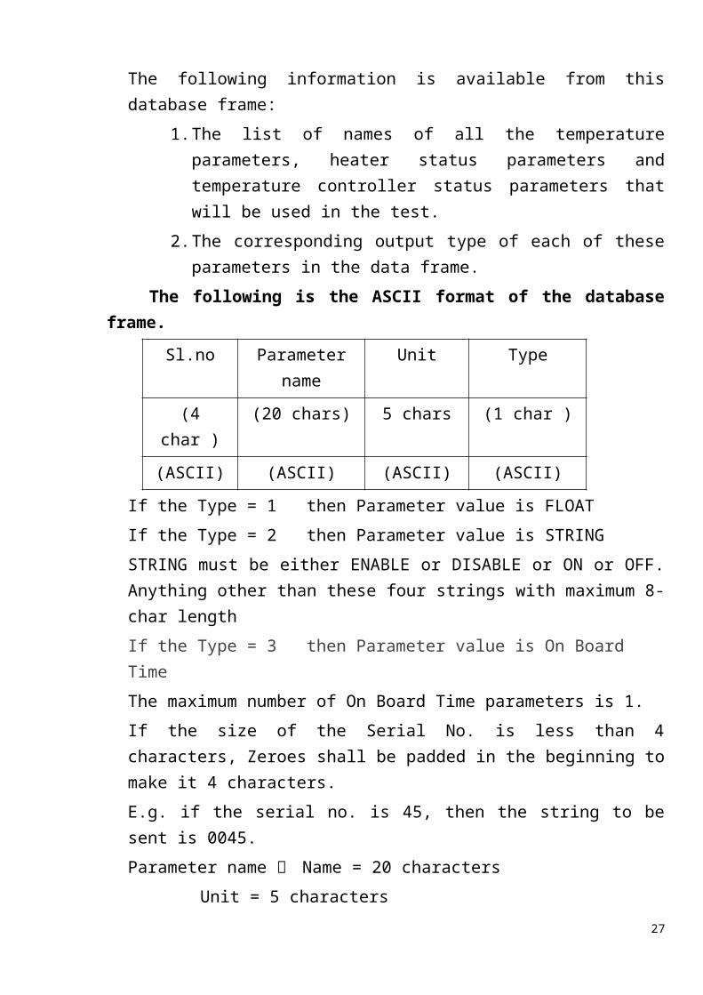
The following is the ASCII format of the database frame.
Sl.no Parameter name Unit Type
(4 char ) (20 chars) 5 chars (1 char )
(ASCII) (ASCII) (ASCII) (ASCII)
If the Type = 1 then Parameter value is FLOATIf the Type = 2 then Parameter value is STRINGSTRING must be either ENABLE or DISABLE or ON or OFF. Anything other than these four strings with maximum 8-char lengthIf the Type = 3 then Parameter value is On Board TimeThe maximum number of On Board Time parameters is 1.If the size of the Serial No. is less than 4 characters, Zeroes shall be padded in the beginning to make it 4 characters.E.g. if the serial no. is 45, then the string to be sent is 0045.Parameter name Name = 20 characters
Unit = 5 charactersE.g.: if parameter name is less than 20 Char then blank char are to be padded at end. Similarly for Unit.This Data Base Frame may be dumped at the beginning of the test or between the Tests.
c. Details of Protocol for Communication between SGCO and ThermalEach data frame contains a Header and processed data in the following order.Header information format a) First byte contains the Start Of the frame STX (02H)
b) Data Frame Type Code is indicated by 1 byte (binary). This indicates the type of the arriving data frame. If data is invalid, the frame is rejected. Frame code for type/Invalid will be as follows:
20
1) Processed Data Frame BBH (1 Byte)2) Processed Data Base Frame CCH (1 Byte)3) Data Invalid Code 00H (1 Byte)
E.g.: when dwelling the TM chian1 or Chain2, the Data Invalid Code to be set
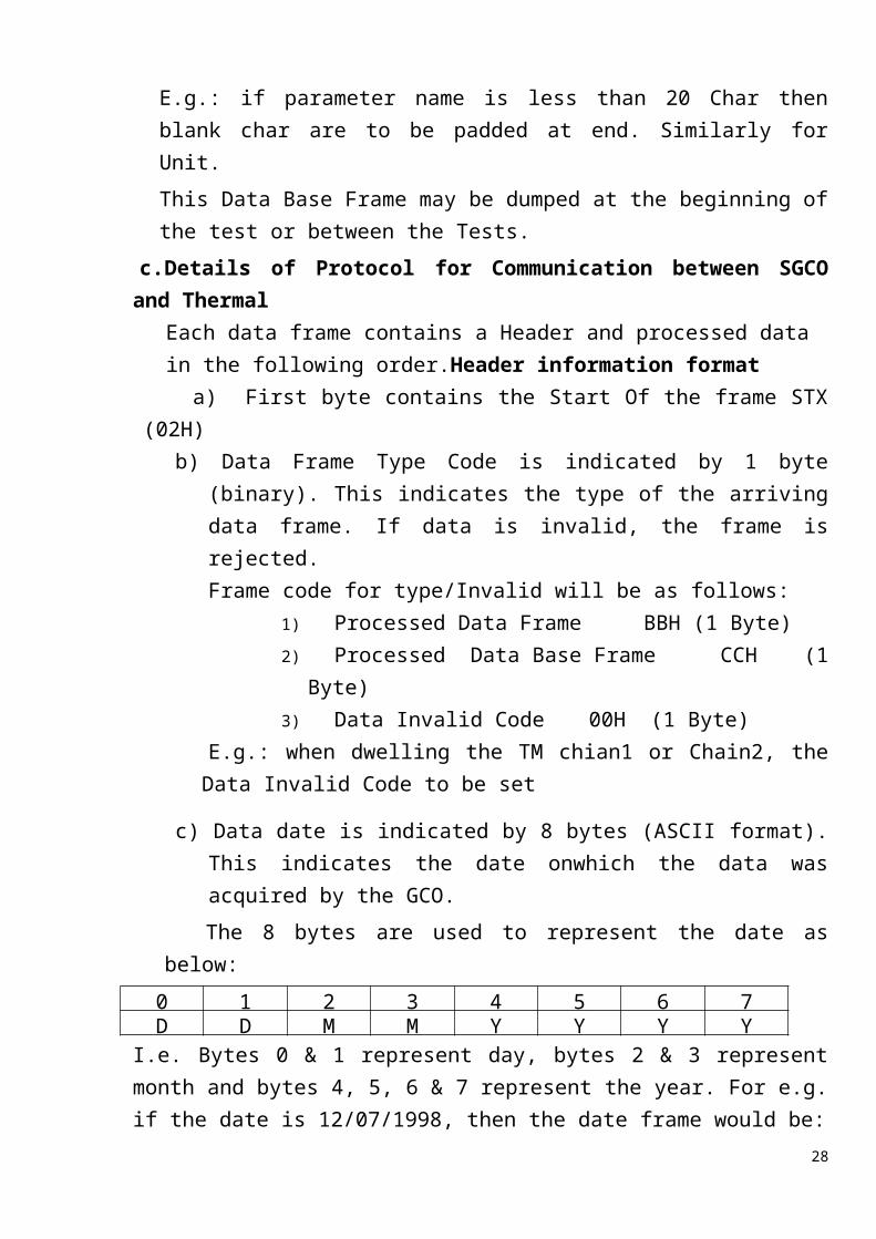
c) Data date is indicated by 8 bytes (ASCII format). This indicates the date onwhich the data was acquired by the GCO. The 8 bytes are used to represent the date as below:
0 1 2 3 4 5 6 7D D M M Y Y Y Y
I.e. Bytes 0 & 1 represent day, bytes 2 & 3 represent month and bytes 4, 5, 6 & 7 represent the year. For e.g. if the date is 12/07/1998, then the date frame would be:
0 1 2 3 4 5 6 731H 32H 30H 37H 31H 39H 39H 38H
d) Data time is indicated by 9 bytes (ASCII format). This indicates at what time the data was acquired by the SGCO. The 9 bytes are used to represent the time as below:
0 1 2 3 4 5 6 7 8H H M M S S MS MS MS
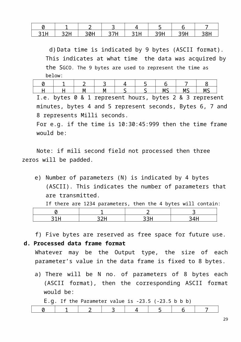
I.e. bytes 0 & 1 represent hours, bytes 2 & 3 represent minutes, bytes 4 and 5 represent seconds, Bytes 6, 7 and 8 represents Milli seconds.For e.g. if the time is 10:30:45:999 then the time frame would be:
Note: if mili second field not processed then three zeros will be padded.
e) Number of parameters (N) is indicated by 4 bytes (ASCII). This indicates the number of parameters that are transmitted.If there are 1234 parameters, then the 4 bytes will contain:
0 1 2 331H 32H 33H 34H
f) Five bytes are reserved as free space for future use.d. Processed data frame format
Whatever may be the Output type, the size of each parameter’s value in the data frame is fixed to 8 bytes.
a) There will be N no. of parameters of 8 bytes each (ASCII format), then the corresponding ASCII format would be:
21
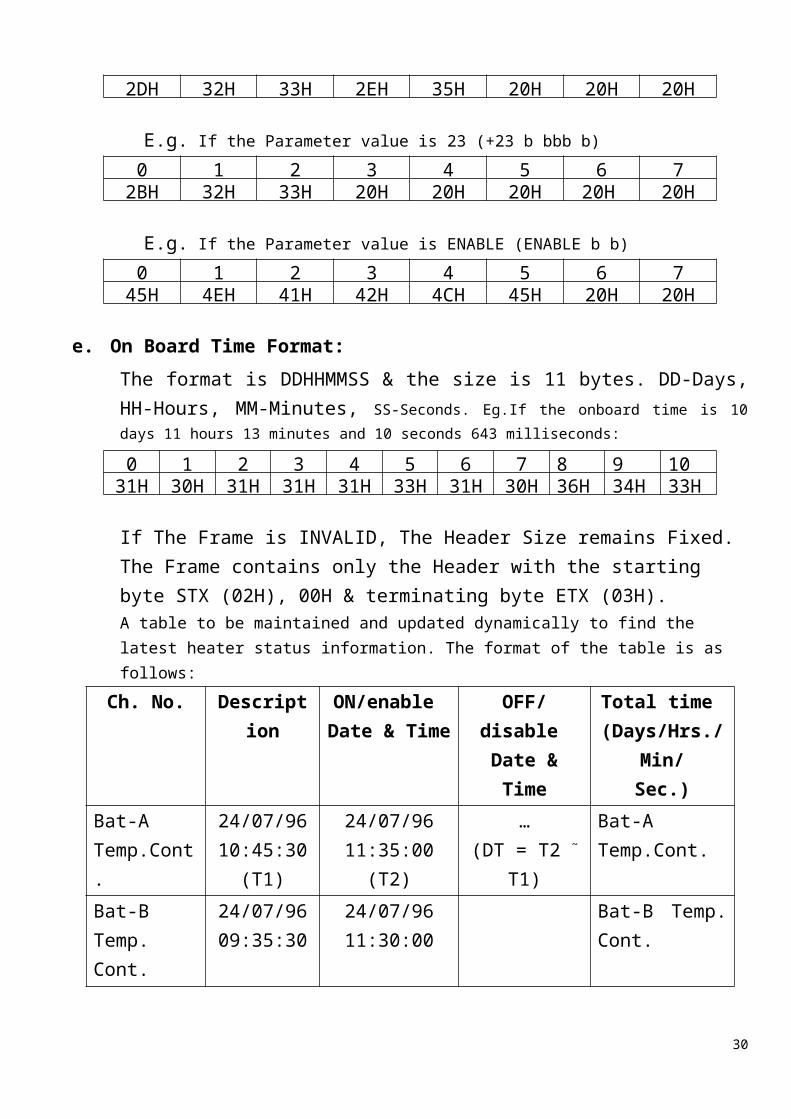
E.g. If the Parameter value is -23.5 (-23.5 b b b)0 1 2 3 4 5 6 7
2DH 32H 33H 2EH 35H 20H 20H 20H
E.g. If the Parameter value is 23 (+23 b bbb b)0 1 2 3 4 5 6 7
2BH 32H 33H 20H 20H 20H 20H 20H
E.g. If the Parameter value is ENABLE (ENABLE b b) 0 1 2 3 4 5 6 7
45H 4EH 41H 42H 4CH 45H 20H 20H
e. On Board Time Format:The format is DDHHMMSS & the size is 11 bytes. DD-Days, HH-Hours, MM-Minutes, SS-Seconds. Eg.If the onboard time is 10 days 11 hours 13 minutes and 10 seconds 643 milliseconds:
0 1 2 3 4 5 6 7 8 9 1031H 30H 31H 31H 31H 33H 31H 30H 36H 34H 33H
If The Frame is INVALID, The Header Size remains Fixed. The Frame contains only the Header with the starting byte STX (02H), 00H & terminating byte ETX (03H).A table to be maintained and updated dynamically to find the latest heater status information. The format of the table is as follows:
Ch. No. Description ON/enable Date & Time
OFF/disable Date & Time
Total time (Days/Hrs./Min/
Sec.)Bat-A Temp.Cont.
24/07/96 10:45:30
(T1)
24/07/96 11:35:00
(T2)
…(DT = T2 ~ T1)
Bat-A Temp.Cont.
Bat-B Temp. Cont.
24/07/96 09:35:30
24/07/96 11:30:00
Bat-B Temp. Cont.
There shall be provision for Calculation of heater duty cycle.9.13 Data Acquisition and processing of CATVAC Parameters
CATVAC parameters to be acquired through Ethernet link with a minimum scan interval of 8 seconds along with acquisition of other parameters as defined in previous sections. The engineering unit data to be processed as any other channels.
9.14 Application software shall be compatible with both LINUX and WINDOWS
22
Environment9.15 Software component shall include:
- Configuration Manager- Diagnostics and Fault Management- Live Data monitor and controller- Historical Data Viewer- History Access Client
9.16 The application software shall be put on main and redundant workstation. 9.17 Unique naming/ Description shall be possible for each sensor and power
Supply. 9.18 There shall be facility for multiple screen display/window. 9.19 The processed data shall be available through network. Any user in the network
shall be able to establish a connection through application software and shall be able to use all the functions of the application software.
9.20 Configuration files9.20.1 There shall be MS-Office or equivalent file format import options for
creating configuration files for a particular test9.20.2 The test configuration file will be created before start of each Spacecraft
test. The Test configuration file will contain the channel numbers used for the test, Descriptions, Temperature limits for channels and any other information required for the test. This file will vary from test to test.
9.20.3 The configuration file for SGCO parameters will be similar and it is a separate file.
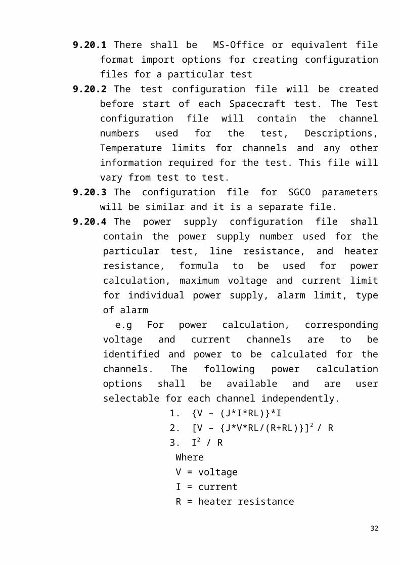
9.20.4 The power supply configuration file shall contain the power supply number used for the particular test, line resistance, and heater resistance, formula to be used for power calculation, maximum voltage and current limit for individual power supply, alarm limit, type of alarm
e.g For power calculation, corresponding voltage and current channels are to be identified and power to be calculated for the channels. The following power calculation options shall be available and are user selectable for each channel independently.
1. {V – (J*I*RL)}*I2. [V – {J*V*RL/(R+RL)}]2 / R3. I2 / R
WhereV = voltageI = currentR = heater resistance
23
RL = heater line resistanceJ = flag (zero or one) to be selected depending on the option to include line loss (J=1) or not to include line loss (J=0)
Heater resistance and heater line resistance will be available in the power supply configuration file.
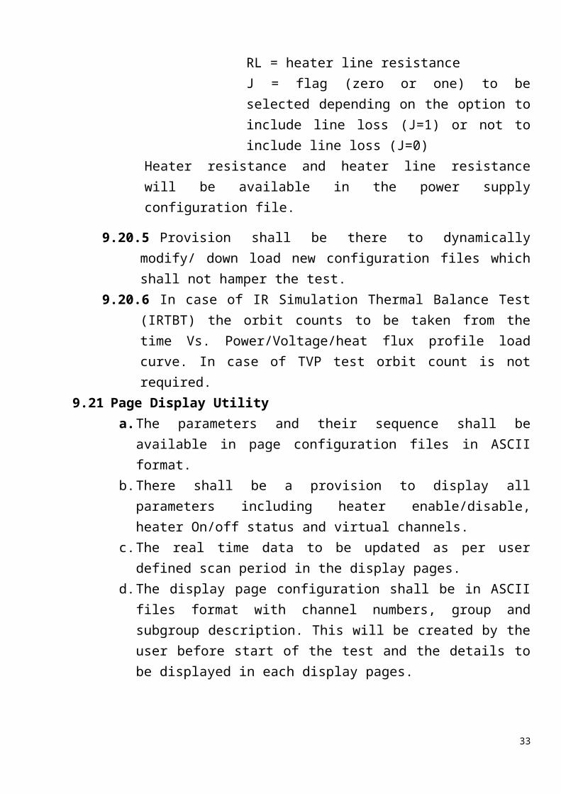
9.20.5 Provision shall be there to dynamically modify/ down load new configuration files which shall not hamper the test.
9.20.6 In case of IR Simulation Thermal Balance Test (IRTBT) the orbit counts to be taken from the time Vs. Power/Voltage/heat flux profile load curve. In case of TVP test orbit count is not required.
9.21 Page Display Utilitya. The parameters and their sequence shall be available in page configuration
files in ASCII format.b. There shall be a provision to display all parameters including heater
enable/disable, heater On/off status and virtual channels.c. The real time data to be updated as per user defined scan period in the
display pages.d. The display page configuration shall be in ASCII files format with
channel numbers, group and subgroup description. This will be created by the user before start of the test and the details to be displayed in each display pages.
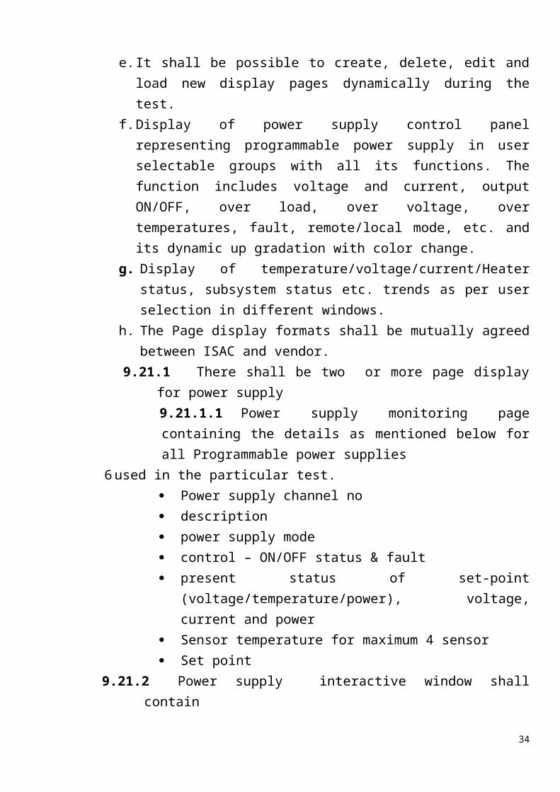
e. It shall be possible to create, delete, edit and load new display pages dynamically during the test.
f. Display of power supply control panel representing programmable power supply in user selectable groups with all its functions. The function includes voltage and current, output ON/OFF, over load, over voltage, over temperatures, fault, remote/local mode, etc. and its dynamic up gradation with color change.
g. Display of temperature/voltage/current/Heater status, subsystem status etc. trends as per user selection in different windows.
h. The Page display formats shall be mutually agreed between ISAC and vendor.
9.21.1 There shall be two or more page display for power supply9.21.1.1 Power supply monitoring page containing the details as mentioned below for all Programmable power supplies
6 used in the particular test. Power supply channel no
24
description power supply mode control – ON/OFF status & fault present status of set-point (voltage/temperature/power), voltage,
current and power Sensor temperature for maximum 4 sensor Set point
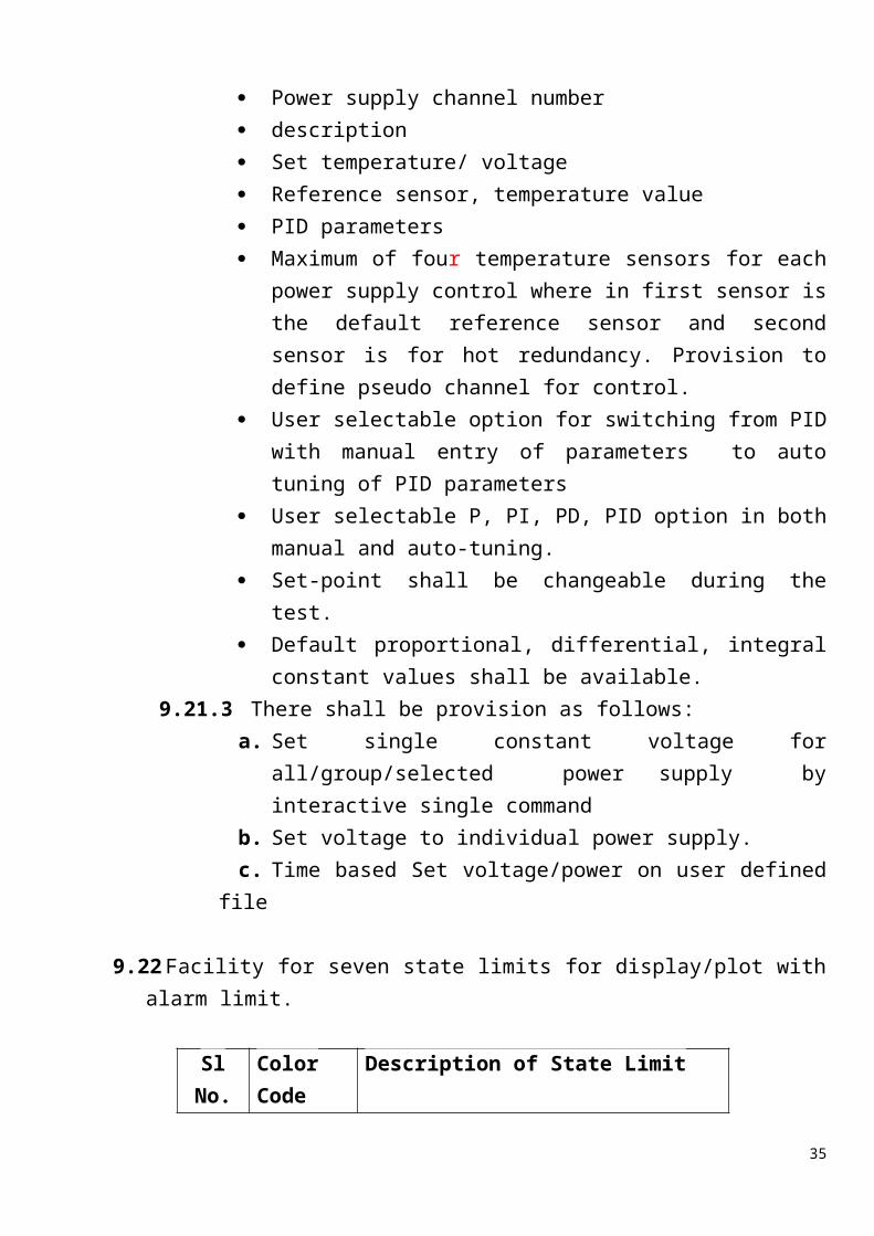
9.21.2 Power supply interactive window shall contain Power supply channel number description Set temperature/ voltage Reference sensor, temperature value PID parameters Maximum of four temperature sensors for each power supply
control where in first sensor is the default reference sensor and second sensor is for hot redundancy. Provision to define pseudo channel for control.
User selectable option for switching from PID with manual entry of parameters to auto tuning of PID parameters
User selectable P, PI, PD, PID option in both manual and auto-tuning.
Set-point shall be changeable during the test. Default proportional, differential, integral constant values shall be
available. 9.21.3 There shall be provision as follows:
a. Set single constant voltage for all/group/selected power supply by interactive single command
b. Set voltage to individual power supply.c. Time based Set voltage/power on user defined file
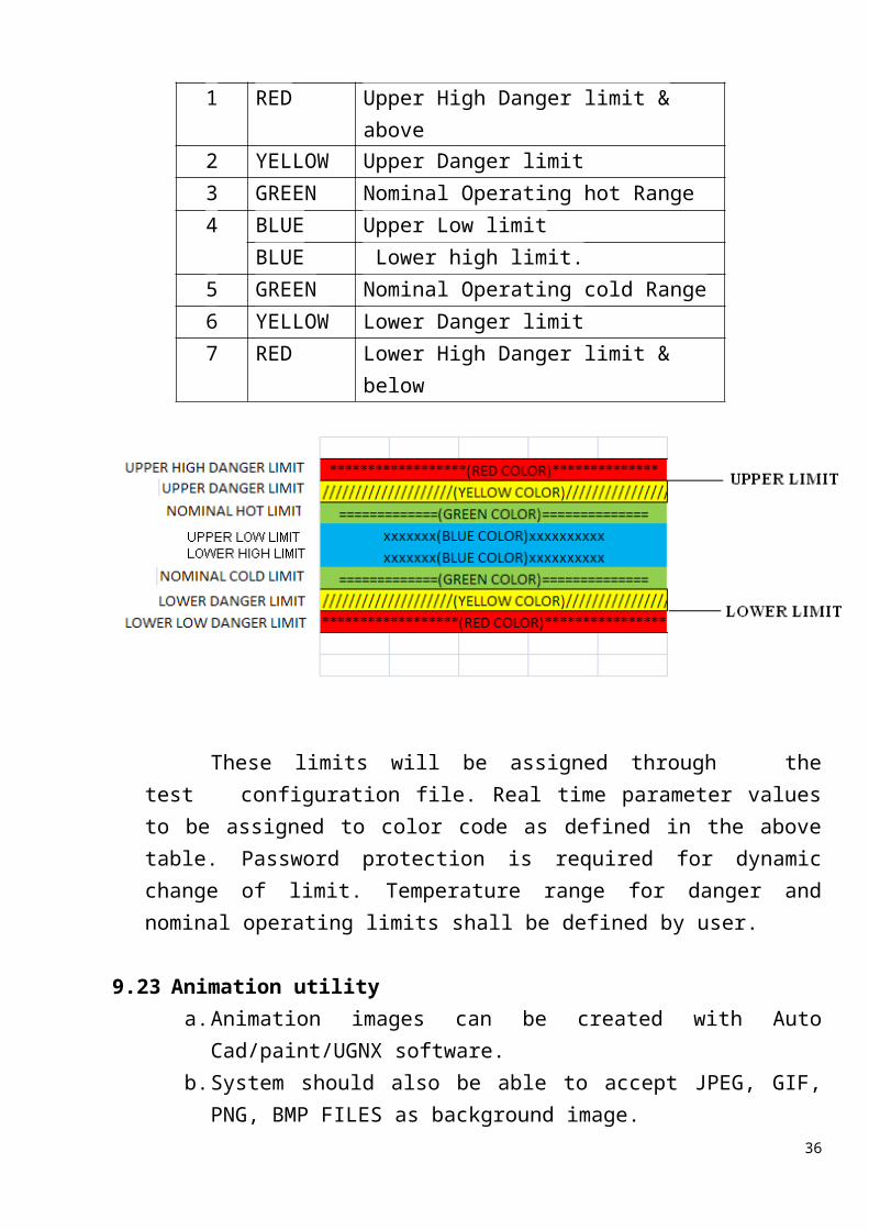
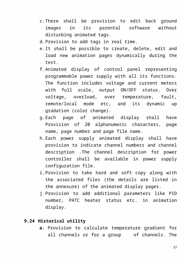
9.22 Facility for seven state limits for display/plot with alarm limit.
Sl No. Color Code
Description of State Limit
1 RED Upper High Danger limit & above2 YELLOW Upper Danger limit3 GREEN Nominal Operating hot Range 4 BLUE Upper Low limit
25
BLUE Lower high limit.5 GREEN Nominal Operating cold Range6 YELLOW Lower Danger limit7 RED Lower High Danger limit & below
These limits will be assigned through the test configuration file. Real time parameter values to be assigned to color code as defined in the above table. Password protection is required for dynamic change of limit. Temperature range for danger and nominal operating limits shall be defined by user.
9.23 Animation utilitya. Animation images can be created with Auto Cad/paint/UGNX software.b. System should also be able to accept JPEG, GIF, PNG, BMP FILES as
background image.c. There shall be provision to edit back ground images in its parental
software without disturbing animated tags.d. Provision to add tags in real time.e. It shall be possible to create, delete, edit and load new animation pages
dynamically during the test.f. Animated display of control panel representing programmable power
supply with all its functions. The function includes voltage and current meters with full scale, output ON/OFF status. Over voltage, overload, over temperature, fault, remote/local mode etc, and its dynamic up gradation (color change).
g. Each page of animated display shall have Provision of 20 alphanumeric characters, page name, page number and page file name.
26
h. Each power supply animated display shall have provision to indicate channel numbers and channel description .The channel description for power controller shall be available in power supply configuration file.
i. Provision to take hard and soft copy along with the associated files (the details are listed in the annexure) of the animated display pages.
j. Provision to add additional parameters like PID number, PATC heater status etc. in animation display.
9.24 Historical utilitya. Provision to calculate temperature gradient for all channels or for a
group of channels. The time interval for gradient calculation shall be user selectable.
b. Provision to calculate Single channel / group of channel average over time.
c. Maximum / Minimum: Single channel / group of channel maximum and minimum over time. The maximum & minimum begins at a given point in time and date and continues through to some other point in time and date.
d. Total power shall be calculated real time / historical for a single/group of power channels defined.
e. Pseudo channels like s/c bus power, total IR lamp power, total test heater power, heat flux shall be available for historical access.
f. Printable historical report generator for daily meeting presentation.g. The web client connected to ISAC INTRANET shall access data using
standard internet browser.h. The application software shall provide multiple offline analyses from
different client.i. Automatic Report generation option shall be available. Vendor has to
submit report formats which has to be approved by ISAC.
9.25 Plot Utilitya. Three type of plot utility shall be available
Historical Real time. Historical-real time
b. In historical plot utility the channel number(s), start & stop date and time shall be defined by the user. In real time plot utility the channel
27
number(s) and only start date and time shall be defined. Data up to current time will have to be picked up from the disk.
c. There shall not be any limitations in number of data points.d. There shall be provision to plot all type of parameters including
computed parameters/pseudo channels and heater and subsystem on/off or Enable/ disable status.
e. Provision to plot a maximum of six parameters (channels) in each plot window and maximum of 6 plot window in a single page with zooming facility.
f. Provision to plot six types of parameters in the same plot window. All 6 scales to be indicated on plot.
g. Provision for user selectable multiple vertical time line maximum 5nos.h. Provision for predefined trend and actual trend for comparison.i. Provision to include user definable lower and higher limits on plot.j. Channels to be identified by different colors and provision to select
symbol with user defined frequency. Symbol shall be tagged with channel description.
k. In case of thermal balance test, provision shall be provided for multiple orbit data along with pre defined data in a single plot.
l. Alarm limits like warning limit, danger limit shall be indicated. It shall be user selectable. Appropriate colors to be used for showing this range.
m. Provision to display channel numbers and 20 character description to identify plot.
n. Provision to define and edit plot heading, plot sub-heading, scales. Provision for auto and manual scale for plotting.
o. Provision to ignore wild samples.p. Provision to define skip factor for plotting.q. Provision to process plot file in batches during and after the test.r. User friendly printable historical report generator for daily meeting
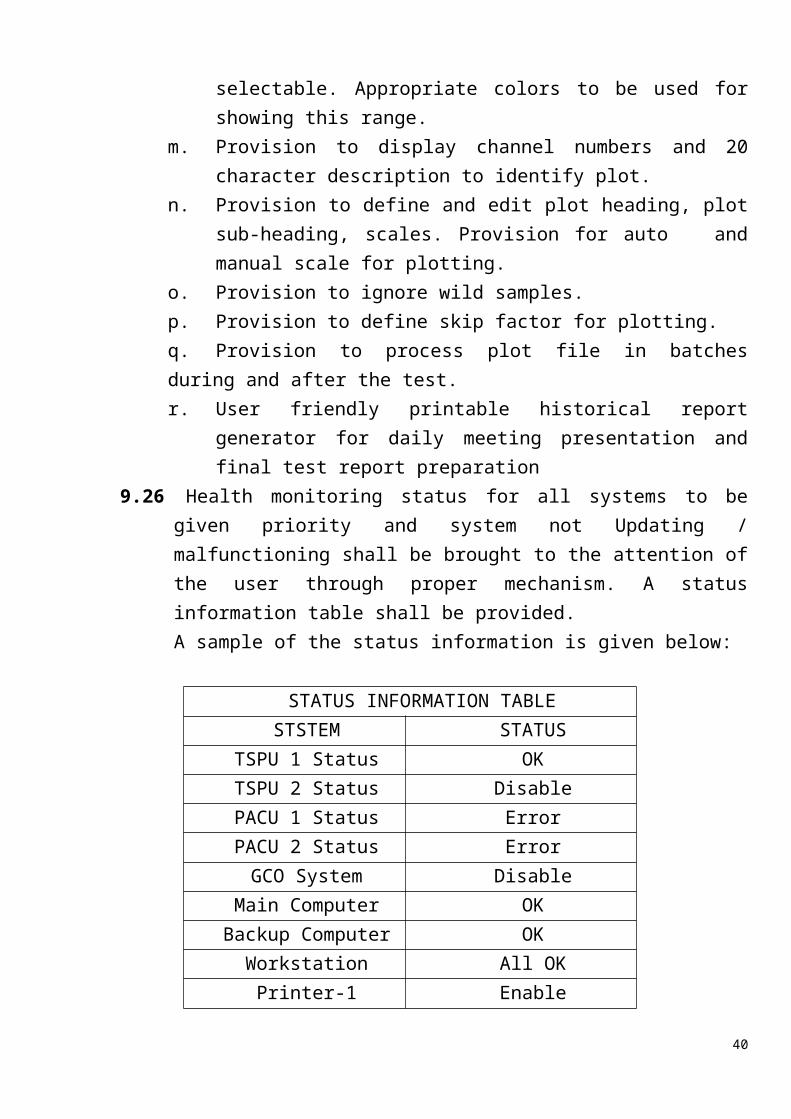
presentation and final test report preparation9.26 Health monitoring status for all systems to be given priority and system not
Updating / malfunctioning shall be brought to the attention of the user through proper mechanism. A status information table shall be provided. A sample of the status information is given below:
STATUS INFORMATION TABLESTSTEM STATUS
28
TSPU 1 Status OKTSPU 2 Status DisablePACU 1 Status ErrorPACU 2 Status ErrorGCO System Disable
Main Computer OKBackup Computer OK
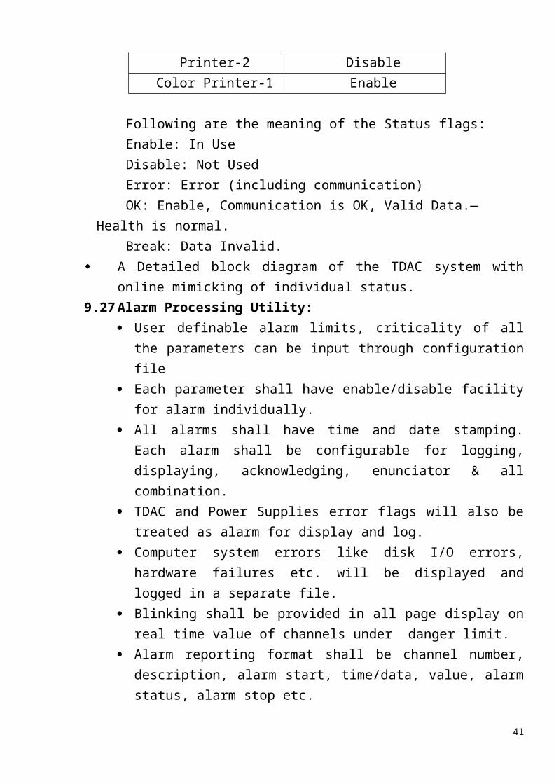
Workstation All OKPrinter-1 EnablePrinter-2 Disable
Color Printer-1 Enable
Following are the meaning of the Status flags:Enable: In UseDisable: Not UsedError: Error (including communication)OK: Enable, Communication is OK, Valid Data.—Health is normal.Break: Data Invalid.
A Detailed block diagram of the TDAC system with online mimicking of individual status.
9.27 Alarm Processing Utility: User definable alarm limits, criticality of all the parameters can be input
through configuration file Each parameter shall have enable/disable facility for alarm individually. All alarms shall have time and date stamping. Each alarm shall be
configurable for logging, displaying, acknowledging, enunciator & all combination.
TDAC and Power Supplies error flags will also be treated as alarm for display and log.
Computer system errors like disk I/O errors, hardware failures etc. will be displayed and logged in a separate file.
Blinking shall be provided in all page display on real time value of channels under danger limit.
Alarm reporting format shall be channel number, description, alarm start, time/data, value, alarm status, alarm stop etc.
Sensors which are danger or high/low danger are considered as Critical and critical alarm shall be displayed in all the screens (scrolling)
29
All temperature sensors can be displayed as tiles on a separate page display screen and it shall be linked to details like channel description, limits etc.
9.28 General
The data files shall be stored in local disk or LTO-6 media storage for redundancy
Logging of data shall include virtual or pseudo channels. Built in web server is required for Remote Monitoring facility. 3 nos. of wall mounted extended display of 40” LED display for display of
user selectable multi display pages simultaneously. Suitable video card/any other hardware & software shall be incorporated by vendor.
Vendor shall provide data storage with RAID capability Vendor shall provide Utility software like MS office tools, adobe reader
etc. System image of each completely configured server should be available
on bootable media to ascertain bare metal recovery. These system images will be useful in system
recovery to a fully operational configuration after disk crash or corruption.
10 Security and Access Controla. Software shall have user administration for different levels of access rights.b. The entire system along with the hardware to be secured from unauthorized
access.c. Upgradeable Antivirus Software Package: Vendor shall quote required
antivirus packages and its upgradeability methodology to be indicated at least for minimum ten years. The internet connectivity to the TDACS would not be provided/ permitted for any kind of security software upload/upgrade.
11 Networking/ All the hardware and accessories involved including ComputerSystems, Data acquisition and Control instrumentation and Peripherals to be Networked (Networking including both – configuration and cable laying).
12 Electrical Cabling Vendor to provide necessary cables and accessories to connect all the systems and peripherals
a) General arrangement drawing / layout of hardware and cabling etc. should be prior approved by ISAC
30
b) Vendor to provide necessary shielded/unshielded cables, extension wires etc between TSPU,DPU,PSPU and 176 no’s of SMPS.
c) The T/C extension cable for 512 nos of T/C channels & the power output cables for 128 nos. of 60V 12.5A SMPS from CATVAC chamber to system area is available. Vendor to provide the signal extension cable for 48 channels of thermistor , 16 channels of PRT and power output cable for 48 nos. of 60V 25A SMPS.
d) Electrical wiring of the system shall meet National Standard Code / safety requirements.
e) Proper labels for cables and I/O ports to be provided as per general networking conventions.
f) Appropriate Schematics to be provided, which provides graphical view of the network topology and generates alerts in the graphical view mentioned above in the event of failures. Failures include failure node, instrumentation, network elements, links and any other device connected to the network.
g) Detailed network connectivity diagram (including IP addresses and labeling info) to be provided by the vendor in soft and hard copy.
h) Three workstations will be located at three different locations and the vendors shall provide the connectivity (with protective conduit) to these workstations.
13 EnvironmentTemperature: 10 to 40CRelative Humidity: 10- 90 %
14 Design review
Vendor shall submit the design and execute schedule and shall be reviewed by ISRO/ ISAC experts / committee for clearance / approval before start of development of the TDACS. For this, Vendor shall submit the design documents, two weeks prior to Design review. This document shall include the various design options, justification for selected options. The suggestions made by ISAC/ISRO experts committee shall be mutually agreed upon by the vendor.
15 Pre-delivery inspection and testing at vendor site
a. The pre-delivery inspection and acceptance test of the complete system shall be carried out by vendor at the vendor premises.
31
b. ISAC / ISRO representative may participate during this pre-delivery inspection and acceptance testing, etc. at the vendor premises.
c. Vendor shall generate and submit the pre-delivery and acceptance test plan document in advance for review and it shall be mutually agreed in between ISAC and vendor prior to the start of the test. Test data report by vendor shall be submitted with one week of completion of test.
d. Clearance to transport / to ship the facility will be given only after review of the test data by ISAC/ISRO.
16 Installation, commissioning & acceptance testing at ISAC/ISRO
a. Installation, testing and commissioning shall be carried out by the VENDOR at ISITE / ISAC / ISRO, Bangalore.
b. Vendor is responsible for unloading, unpacking, erection, installation and commissioning of total facility at ISITE / ISAC / ISRO - Bangalore.
c. As a part of system commissioning at ISITE, vendor shall demonstrate end to end complete system performance. For this, vendor shall generate and submit acceptance test plan document in advance for ISRO/ISAC review and it shall be mutually agreed in between ISAC and vendor prior to the start of the test. Final acceptance Test report by vendor shall be submitted with one week of completion of test.
d. Final acceptance of the facility is subjected to the successful demonstration of the performance test conducted at the time of commissioning at ISAC.
e. No logistic / tool support, in any form, until unless specified in the final contract, will be provided by ISAC / ISRO. Vendor shall consider only the normal working hours - 08:30AM to 05:00PM from Monday to Friday (excluding holidays declared by ISAC / ISRO).
f. Vendor shall participate during one of the satellite testing round the clock shift to demonstrate satisfactory performance of the system in real environment.
17 Training
32
a. Supplier shall provide mandatory training on operation and routine maintenance of the complete system to about four numbers of ISAC personnel at ISAC / ISRO as part of installation and commissioning.
b. Language of all correspondence, information , training, documentation etc. shall be in English
18 Deliverable Documents:
Hard /and soft copy of the following documents / information, but not limited to, are required to be submitted by the vendor.
1. System management Plan at T0 (date of the award of contract) +1 week.2. Software Requirements Specification(SRS) document3. Detailed System Design and Specification Compliance Document4. Software high level design document5. Software development life cycle plan6. Software requirements tracability document7. Acceptance test and system evaluation plan(ATP) document8. Acceptance test report(ATR) with test cases.9. Calibration data and certificates 10.Pre-dispatch inspection and test report before dispatch of system to ISAC
/ISRO-Bangalore.11.The following documents shall be supplied by the vendor along with the system.
User manuals. Operation manuals. Service and maintenance manual. System Hardware Documentation. Network design and configuration Documentation
12.Configuration and setup documentation on RDBMS for various required configuration.
13.Instrument Interface documentation with hardware and software including protocol and data frame structure for existing and new instruments.
14.Software Documentation 15.Software installation Kit CD/DVD for application software with documentation16.Backup and recovery plan document.17.Contingency recovery plan/ procedure, fault diagnosis18.All necessary license software/certificate shall be provided.19.Software code.
33
19 Tentative Delivery Schedule
I. T0 = Placing the orderII. T0+ 1 week – System management plan.
III. T0 +3 months = Submission of “Detailed Design Review and Specification Compliance Document.”
IV. T0 +4 months = Detailed Design Review.V. T1 = T0 +12 months = Acceptance test at Vendors Site and ISAC Clearance
VI. T2 = T1 +1 months =Delivery VII. T2 + 4 months=Installation & Commissioning at ISAC
20. Warranty
a. 5 year onsite parts and labour warranty from the date of acceptance of the system. Warranty shall include complete hardware, software support including operating system and application software with licenses.
b. During this warranty period, vendor shall carry routine maintenance, System validation at every three month or before start of any major test, up keeping of maintenance record, quarterly modification/up gradation in both software and hardware if any called for during the process of running/ usage of the system.
c. Any failure /break down shall be attended by system engineer within 2 hours during test and within 24 hours during non-test period.
d. The details of services, periodic preventive maintenance schedules, manpower deployment to support above activities during warranty shall be given in quote.
21. Instruction to vendors for submitting offer
Offer shall be submitted in two parts as following: Part-1 is “Techno- Commercial part ( without price detail) ” and Part-2 is “Commercial part (Price offer)”. Both the parts are to be submitted simultaneously in two separate sealed covers.
21.1. PART-1: Techno-commercial part (without price detail) shall include the following:
a. Technical compliance statement shall be given in point-wise for all of our specifications. “Complied” against each of the specification points should be supported with data/ numerical values/ catalogs.
34
b. Any deviation in specification leading to better performance is to be clearly highlighted with merits.
c. Offers without compliance matrix, will not be considered.d. Necessary support documents to meet the RFQ requiremente. List of any other recommended spares and accessories for 5 years of post
warranty operations and assurance for supply of any spares of the facility for the above period from the date of commissioning. (optional)
f. It should be exact replica of the commercial price bid without price information i.e., un-priced commercial bid.
g. Vendor shall add items not mentioned in the format but is necessary to fulfill the applications, installation and commissioning of the system.
h. Delivery period.i. Warranty Period.j. Post Warranty non comprehensive AMC for 5 years.(optional)k. Deliverablesl. Packaging and shipment plan.
21.2. PART-2: commercial part (price detail) shall include the followinga. Cost breakup for hardware and software units as per RFQ format. b. Vendor shall add price of items which are not mentioned in the format but
is necessary to fulfill the applications, installation and commissioning of the system.
c. Cost of Spares as per RFQ. The cost of spares will not be considered in “Lowest Technical Suitable Offer” evaluation.
d. Cost of accessories to complete the taske. Non comprehensive AMC charge for further 5 years of post warrantee
period. AMC charge shall include routine maintenance, System validation at 3 months interval, up keeping of maintenance record, quarterly modification/up gradation in both software and hardware if any called for during the process of running/ usage of the system.
f. Item wise cost for any other recommended spares and accessories for 10 years of operations.
g. Vendor shall submit commercial terms and conditions like payment terms & conditions, validity, details of taxes, duties and statutory levies applicable.
35
Format for commercial bid
Hardware Deliverables:
Sl. No Description
Make / Model Quantity
Total cost (Rs.)
1.
Temperature signal processing Unit for monitoring 256 T type thermocouple, 48 thermistors and 16 platinum resistance temperature sensor
Controller cards
Extension Cable for 96 thermistors & 32 PRT sensor(4 wire)- Length of cable – 80 meters
accessories
Rack / Cabinet
2.
Power supply processing Unit for 256 channels (with redundant controller )
Embedded Controller
Extension Cable for 48 power supply output of rating 60V/ 30A. Length of cable – 80 meters
accessories
Associated cables, power strips, terminal block, MCBs etc
Rack / Cabinet
3.
Switching mode Programmable Power supplies Input 230V AC +/- 15%Output: 0-60 VDC 0-12AOutput 0-60 VDC 0-25A
cable
accessories
Rack / Cabinet
4. Data processing unit
server
Work stations
36
Sl. No Description
Make / Model Quantity
Total cost (Rs.)
Extended display screen 40 inch OR better(quote -optional)
Associated cables, power strips, terminal block, MCBs etc
Printers (black and white)(duplex)
scanner
Color printer(duplex)
Rack / Cabinet
Data backup storage device
Switch, network cable
External Storage unit
accessories
Software Deliverables:
Sl. No. Description Quantity Total cost
(Rs.)
1. Application software license
2. Web client viewer software license
3. Software code
4. Latest version of MS-office license
5. ACAD licence
7.Operating system licenses Red hat enterprises latest version linuxWindow 8.1 or better
8. Any other Supporting software licenses
Hardware Spares, tools:
Sl. No. Description Make /
Model Quantity Total cost (Rs.)
1.
37
Software Spares:
Sl. No. Description Quantity Total cost (Rs.)
1.
2.
Packaging & forwarding:
Sl. No. Description Total cost (Rs.)
1. Packaging and forwarding charges, freight charges
Total
Installation & Commissioning:
Sl. No. Description Total cost (Rs.)
1. Pre-dispatch / factory acceptance testing
2. Installation and commissioning
3. Ttraining for operation and maintenance of total system at ISAC
4. On-site support during Warranty Period
5 Extended warranty of 5 years( optional)
Taxes and Duties:
Sl. No. Description Taxes Price (Rs.)
1. Hardware deliverables
2. Software deliverables
3. Hardware spares
4. Software spares
5. Packaging & forwarding
6.Installation & commissioning at ISAC & On-site support, training, Extended Warranty etc.
38
ANNEXURE: A
Details of thermal simulation / thermal instrumentation on spacecraft/ electronics packages for conducting thermal testsThermal tests are categorized into
Thermal balance test(TBT) – for verifying thermal design of spacecraft and demonstrating the ability of thermal control system in maintaining temperatures of spacecraft within specified limits.
Thermal vacuum performance test (TVP) - for verifying the electrical performance of spacecraft under vacuum and at the extreme hot and extreme cold qualification / acceptance temperatures.
Typical thermal instrumentation for conducting above test is as follows:
Temperature sensors (Thermistors, Platinum Resistance Temperature sensors)
Electrical heaters ( Foil heaters, tape heaters)
Infrared lamps are used in front of spacecraft panel at a distance of 250-300mm.
Test temperature sensors – generally T-type thermocouples are also instrumented with redundancy at critical locations for temperature control and additional monitoring purpose.
The heaters and IR lamps are divided into number of temperature control zones depending up location of subsystems and their extreme temperature limits, kind of thermal control system etc.
Spacecraft is placed inside the vacuum chamber. Chamber temperature may vary from -100ºC to +100 ºC. vacuum maintained at 10-5 bar or better.
Thermal test instrumentation is connected to computer based data acquisition and power supply / control system (TDAC). Temperatures of all the subsystems are continuously monitored and controlled by TDAC using PID control loop as shown in following figure
39
CONTROL REF. SENSOR
SPACECRAFT PANEL OUTSIDE
ELECTRONIC PACKAGE INSIDE PANEL
INFRA RED LAMP
1
23
4CHAMBER TEMPERATURE
PID TDAC
ANNEXURE-B SPECIFICATION OF DPU HARDWARE
Specification of servers (3 nos.)(rack mountable)
Feature Specifications
Make HP/Sun/IBM/Lenovo/Dell/Fujtisu/Oracle/CISCO
Quantity 3 Nos
Processor 2 Nos: Intel Xeon processors E5-2637 v3 or better series,2.4 GHz or better, Minimum 8 MB L3 cache, 1866 MHz memory,Quad-core
Chipset Intel/OEM Chipset on OEM motherboard compatible with quoted processor
Memory 16 GB-DDR4 ECC buffered Memory,1866 MHz, at least 2 DIMM slots free
Hard Disk and controller
02 Nos. of Hot pluggable 300GB SAS 10K RPM 6Gbps HDDs, the internal storage should be configured in RAID 10
Storage controller capable of providing RAID0/1/10 configuration with atleast 256 MB battery backed up write cache.
Expansion slots Minimum of 1 PCIe/PCI/PCI-X based free slots after installation of all required devices.
Interface Card 8 Gbps dual port HBA Card (To connect Tape drive)
Network Gigabit Ethernet 10/100/1000 Mbps with RJ45 connector - 6 ports on 3 separate controllers.
USB ports 04 Nos. of USB 2.0 ports with at-least two USB ports should be on front side
Management
Should provide remote management port and software capable of providing graphical interface
Server management software should be of the same brand as the OEM
Power supply 220 V AC@50Hz with rack power chords. 16XDVD (RW or better)Media driver
Form factor NOT more than 4U
Rail Kit Sliding rail kit with cable management arm for mounting on a 19” standard rack
Other configuration Redundant hot plug power supplyRedundant hot plug system fan2 out of 3 servers to be configured for connecting to and using shared iSCSI storage.The servers will be configured in a cluster for high availability and compatibility with proposed shared iSCSI storage in NO SPOF(SINGLE POINT OF FAILURE)mode, the bidder should include costs for above implementation and should provide any
40
software/hardware/licenses required for the same.
System image of each completely configured server should be available on bootable media to ascertain bare metal recovery, these systems images will be useful in system recovery to a fully operational configuration after disk crash or corruption.
warranty
5 years onsite parts and labor warranty for systems (including backlight) from OEM. The warranty should also include BIOS upgrades, firmware upgrades and maintenance, trouble shooting at site
Industry standards System should be fully compliant with industry standards.
OS certification System should be certified for Red Hat Enterprise Linux
Vendor Status
The manufacturer / Vendor must have a strong proven service network in Bangalore, serving other public sector / Government and other reputed establishments, to provide comprehensive first point of contact service. List of the clients should be enclosed with PO details.
Safety Certification FCC for EMI and UL for safety.
Energy Conservation System power supply should be 80PLUS certified
Specifications: RedHat Enterprise Linux OS (03 Numbers)
S.No Specifications Description
1 Operating System Red-Hat Enterprise Linux, 2 sockets and 1 Yr standard subscription & License
2 Subscription Vendor should provide1 Yr Standard subscription for Red Hat Enterprise Linux Server OS for 2 socket servers
3 Installation Vendor to install latest version of Operating System (RHEL)
4 OS updates/New Releases All Operating System updates/upgrades/new versions released during subscription period should be provided/down-loadable at no extra cost
41
Specifications of workstations (10 nos.)
1. Make HP/IBM/Lenovo/Dell/Fujtisu/Oracle/CISCO
2 Quantity 10 nos
3 Processor Single Intel Xeon processor of E5-2637 v3 or better series, 2.4 GHz or better, Minimum 8 MB L3 cache, 1866 MHz memory, Quad-Core
4 Chipset Intel/OEM Chipset on OEM motherboard compatible with quoted processor
5 Memory 8 GB - DDR4 ECC buffered Memory, 1866 MHz, at least 2 DIMM slots free
6 Hard drive 2 Nos : 600 GB (10000 rpm) SATA 3 Gbps or better
7 Drive Controller
3 Gbps or better SATA controller for handling SATA disks as per the disks mentioned above
8 Graphics Card
NVIDIA Quadro K420 compatible with above-mentioned Processor
9 Audio Integrated audio with internal / powered speakers
10 Slots /Bays Minimum ONE PCI/PCIe/PCI-X expansion slots free after configuring all the required devices.
11 VGA Port 1 VGA port to connect monitor
12 Optical Drive
16 X or better DVD+/-RW
13 Network Interface
Dual port Gigabit Ethernet 10/100/1000 Mbps with RJ45 connector
14 Monitor 21 inch diagonal, Active Matrix TFT with standard aspect ratio and supporting resolution of 1920 x 1200 or better 50/60 Hz. Monitor make should be same as that of workstation
15 Keyboard Minimum 104 keys with additional shortcut keys. Interface – USB
16 Mouse USB 2 Button scroll optical mouse
17 USB ports 4 USB 2.0 ports with minimum of 2 USB 2.0 ports in front side
18 Operating System
System should be certified for Red Hat Enterprise Linux 2 out of 10 system should have Genuine Windows 8.1 Pro or Windows 10 Pro, 64-bit English with recovery media.
19 OS Certification
Systems should be certified for above-mentioned Windows OS
20 Power Supply
220 V AC @ 50 Hz with standard power cords.
21 Warranty 5 years onsite parts and labour warranty for system and monitor (including backlight) from OEM. The warranty should also include BIOS upgrades, firmware upgrades and maintenance, troubleshooting at site
42
22 Industry standards
System should be fully compliant with industry standards.
23 Vendor Status
The manufacturer / Vendor must have a strong proven service network in Bangalore, serving other public sector / Government and other reputed establishments, to provide comprehensive first point of contact service. List of the clients should be enclosed.
24 Safety Certification
FCC for EMI and UL for safety.
Specifications: Windows 8.1 Pro or Windows 10 Pro, 64-bit English with recovery media 2 Nos.
Sl.no Specifications Description
1 Operating System Windows 8.1 Pro or Windows 10 Pro, 64-bit English with recovery media. 1 Yr standard subscription & License
2 Subscription Vendor should provide1 Yr Standard subscription for for 2 socket workstation
3 Installation Vendor to install latest version of Operating System
4 OS updates/New Releases All Operating System updates/upgrades/new versions released during subscription period should be provided/down-loadable at no extra cost
43
Specification of Rack
S N Parameter Functionality
1 Make Same as server OEM Make/ APC/ Rittal/ Valrack
2 Rack Size Suitable size 19” standard rack with four independent PDUs and eight powerOutlets per PDU or better and cable management units (Please specify size of Rack in number of 1.75” Us).Appropriate gap between devices ( Servers, Ethernet switches, Storage, backupTape etc.) To be maintained to take care of cooling.
3 KVM 8 port KVM Switch to monitor & control 8 computers Rack mount keyboard with integrated mouse pad Provision to connect USB keyboard and V mouseFoldable 17” TFT monitor.Appropriate cables to be provided to connect all the servers.
4 Others All Servers, Ethernet switches, Storage, backup device should be mounted onthe rack.Proper cabling and dressing to be carried out by the vendor using patch panels.
5 Warranty 5 years onsite parts and labour warranty
6 Others The front door should be transparent /perforated and lockable.Compatibility of devices (Servers, Ethernet switches, Storage, backup tape etc.) with Rack to be ensured.
Specification of iSCSI Storage 1 Set.
S N Parameter Functionality
1 Make IBM / HP / Sun/ EMC / Net app/ Hitachi
2 Operation systems support
1. The storage array should support industry-leading Operating Systemplatforms including: Windows Server 2012 (Enterprise Edition) andLinux for attached hosts.
3 (a) Capacity & Scalability
1. Minimum 10 TB (usable capacity). To be configured for RAID 5 or better configuration and appropriate snapshot areaUsable capacity is the disk capacity available on LINUX host with command df-h.Hardware RAID supportAt least one hot spare disk
(b) Disk Drive 20 No’s of 6 Gbps per port, dual-ported 900 GB, 10K RPM hot-pluggableSAS drives with RAID-5 or better configuration
4 Processing Power Minimum 10,000cache iops.
5 No Single point of Offered Storage Array shall be configured in a No Single Point of failure
44
Failure configuration including Ethernet cards, Cache memory, FAN, Power supply etc.
6 Management Port 10/100/1000BASE-T port for management to be provided.
7 Host Ports & Back-end Ports
Offered Storage shall have minimum of 4 Giga Ethernet Ports for connectivity to servers. Storage and 2 Servers per set to be configured in Iscsi configuration.
Additional interface 8 Gbps FC ports 2 numbers.
8 Storage ArrayConfiguration &Management Software
Vendor shall provide Storage Array configuration and Management software.
9 Rack mount Storage should be rack mountable in standard 19” rack. Please specify form factor.
10 Warranty 5 years onsite parts and labor warranty from OEM. The warranty should also include firmware upgrades and maintenance, troubleshooting at site.
Specifications for Managed Gigabit Ethernet 8 Port L2 switches –1 Set (2 no’s) (For connecting Servers to ISCSI external storage)
Sl.no Parameter Description Requirements
1 Ethernet Switches (MakeFoundry/CISCO)
Native 1 Gbps Ethernet 8 Port L2 Switch with minimum 08 10/100/1000 BASE-T ports. Back to back Interconnect to be provided along with the cable.
2 Switch Capacity 24 Gbps
3 Maximum 64 bytes packetforwarding rate
14 Mpps
4 Monitor &Management Switch should provide capability to monitor and manage the switcheither using GUI or Web browser.
5 Auto sense Switch should provide capability for auto sense 10/100/1000 bps.
6 RPS Redundant hot plug power supply
7 Documentation The original user’s manual and all related technical manuals to beProvided.
8 Support Vendor should not offer an obsolete product, which has already reached end-of-sale or whose end-of-sale is within 3 months of last date of tender. these Switches to be configured in auto fail-over mode
9 Warranty 5 years onsite parts and labour warranty including firmware upgrades and maintenance , troubleshooting at site
45
Specifications for Managed Gigabit Ethernet L2+ Switches possible to define static routes for 50 networks
Sl.no
Parameter Description Requirements
1 Ethernet Switches (MakeFoundry/CISCO/HP)
Native 1 Gbps Ethernet 24 Port L2+ Switch with minimum 2410/100/1000 BASE-T ports. Back to back Interconnect to be providedalong with the cable.
2 Switch Capacity 48 Gbps
3 Maximum 64 bytes packetforwarding rate
32 Mpps
4 Monitorand Management
Switch should provide capability to monitor and manage the switcheither using GUI or Web browser
5 Auto sense Switch should provide capability for auto sense 10/100/1000 bps.
6 RPS Redundant hot plug power supply
7 Documentation The original user’s manual and all related technical manuals to beprovided.
8 Support Vendor should not offer an obsolete product, which has already reached end-of-sale or whose end-of-sale is within 2 months of lastdate of tender.VLAN support.Vendor to configure required VLANs (4 nos) for GCO, Facilities,TSG and TDACS and configure inter VLAN routing.These Switches to be configured in auto fail-over mode
9 Warranty 5 years onsite parts and labour warranty including firmware upgradesand maintenance , troubleshooting at site
Specifications for LTO-6 tape Drive
Sl.no
Parameter Description Requirements
1 Tape Drive LTO-6 or better
2 Interface 8 Gbps FC interface
3 No of drives 2 Nos
4 Software Required compatible software and drivers
5 Support Support for the offered product shall be available for 10 years from the date of acceptance. Vendors shall offer a product whose end of sale is at least 3 years from the last date of tender.
6 Warranty 5 years onsite parts and labour warranty including firmware upgrades and maintenance, troubleshooting at site
46
LTO-6 media 6 Nos.
Power supply racks
- Aluminum extruded rack frame along with side, Top, Bottom, front and rare panel made of steel with following feature
- Rack dimension: (approximate) Height (Usable): 42U Width (Overall): 800mm Depth (Overall): 800mm Front and rare door: With lock and key Front door glass for visibility Top and Bottom Cover: with vented top cover Side panel: Removable type 19” mount for mounting card frame and instruments Load carrying capacity of about 300Kg Suitable fan for temperature control Temperature indicator on each rack Internal lamp 8 Pair support angle made of steel
- Preferably all the 176 Numbers of power supplies (SMPS) loaded within 5 racks. Rack shall be engineered for easy mounting and removal of power supplies. Rack shall be designed to take care of 30 days of continuous operation of all 176 power supplies at full load. Thermal cooling of the racks to be addressed while engineering the SMPS racks.
- EMI/RFI interference should be as per applicable MIL standard
47
ANNEXURE C: DPU block diagram
48
ANNEXURE D: floor area for TDACS
LAYOUT OF EXISTING DATA ACQUISITION SYSTEM
49
9.0m