Embed Size (px)
Citation preview
Lenovo RackSwitch G7028/G7052
ISCLI—Industry Standard CLI Command Referencefor Networking OS 8.1

Note: Before using this information and the product it supports, read the general information in the Safety information and Environmental Notices and User Guide documents on the Lenovo Documentation CD and the Warranty Information document that comes with the product.
First Edition (August 2015)© Copyright Lenovo 2015Portions © Copyright IBM Corporation 2014.LIMITED AND RESTRICTED RIGHTS NOTICE: If data or software is delivered pursuant a General Services Administration “GSA” contract, use, reproduction, or disclosure is subject to restrictions set forth in Contract No. GS-35F-05925.Lenovo and the Lenovo logo are trademarks of Lenovo in the United States, other countries or both.
© Copyright Lenovo 2015 3
Contents
Preface . . . . . . . . . . . . . . . . . . . . . . . . . . . . 11Who Should Use This Book . . . . . . . . . . . . . . . . . . . . . . .12How This Book Is Organized . . . . . . . . . . . . . . . . . . . . . . .13Typographic Conventions . . . . . . . . . . . . . . . . . . . . . . . .14
Chapter 1. ISCLI Basics . . . . . . . . . . . . . . . . . . . . . 17ISCLI Command Modes . . . . . . . . . . . . . . . . . . . . . . . . .18Global Commands . . . . . . . . . . . . . . . . . . . . . . . . . . .20Command Line Interface Shortcuts . . . . . . . . . . . . . . . . . . . .23
CLI List and Range Inputs . . . . . . . . . . . . . . . . . . . . . .23Command Abbreviation . . . . . . . . . . . . . . . . . . . . . . .23Tab Completion. . . . . . . . . . . . . . . . . . . . . . . . . . .23
User Access Levels . . . . . . . . . . . . . . . . . . . . . . . . . . .24Idle Timeout . . . . . . . . . . . . . . . . . . . . . . . . . . . . . .25
Chapter 2. Information Commands. . . . . . . . . . . . . . . . . 27System Information . . . . . . . . . . . . . . . . . . . . . . . . . . .28
CLI Display Information . . . . . . . . . . . . . . . . . . . . . . .30Error Disable and Recovery Information . . . . . . . . . . . . . . . .31SNMPv3 System Information . . . . . . . . . . . . . . . . . . . . .32
SNMPv3 USM User Table Information . . . . . . . . . . . . . . .33SNMPv3 View Table Information . . . . . . . . . . . . . . . . .34SNMPv3 Access Table Information . . . . . . . . . . . . . . . .35SNMPv3 Group Table Information. . . . . . . . . . . . . . . . .36SNMPv3 Community Table Information . . . . . . . . . . . . . .36SNMPv3 Target Address Table Information . . . . . . . . . . . . .37SNMPv3 Target Parameters Table Information . . . . . . . . . . .38SNMPv3 Notify Table Information. . . . . . . . . . . . . . . . .38SNMPv3 Dump Information . . . . . . . . . . . . . . . . . . .39
General System Information . . . . . . . . . . . . . . . . . . . . .40Show Specific System Information . . . . . . . . . . . . . . . . .41
Show Recent Syslog Messages . . . . . . . . . . . . . . . . . . . .42User Status . . . . . . . . . . . . . . . . . . . . . . . . . . . . .43
Layer 2 Information . . . . . . . . . . . . . . . . . . . . . . . . . . .44802.1X Information . . . . . . . . . . . . . . . . . . . . . . . . .47FDB Information . . . . . . . . . . . . . . . . . . . . . . . . . .49
FDB Multicast Information . . . . . . . . . . . . . . . . . . . .50Show All FDB Information . . . . . . . . . . . . . . . . . . . .51Clearing Entries from the Forwarding Database . . . . . . . . . . .51
Link Aggregation Control Protocol Information . . . . . . . . . . . . .52Link Aggregation Control Protocol . . . . . . . . . . . . . . . .53
Layer 2 Failover Information . . . . . . . . . . . . . . . . . . . . .54Layer 2 Failover Information . . . . . . . . . . . . . . . . . . .54
Hot Links Information . . . . . . . . . . . . . . . . . . . . . . . .56LLDP Information. . . . . . . . . . . . . . . . . . . . . . . . . .57
LLDP Remote Device Information . . . . . . . . . . . . . . . . .58Unidirectional Link Detection Information . . . . . . . . . . . . . . .59
4 G7028/G7052 Command Reference for N/OS 8.1
UDLD Port Information . . . . . . . . . . . . . . . . . . . . . 59802.1x Discovery Information. . . . . . . . . . . . . . . . . . . . . 60
802.1x Port Information . . . . . . . . . . . . . . . . . . . . . 60vLAG Information . . . . . . . . . . . . . . . . . . . . . . . . . 61
vLAG Aggregation Information . . . . . . . . . . . . . . . . . . 62Spanning Tree Information. . . . . . . . . . . . . . . . . . . . . . 63
RSTP Information . . . . . . . . . . . . . . . . . . . . . . . . 64PVRST Information . . . . . . . . . . . . . . . . . . . . . . . 66Spanning Tree Bridge Information. . . . . . . . . . . . . . . . . 68Spanning Tree Root Information . . . . . . . . . . . . . . . . . 69Multiple Spanning Tree Information . . . . . . . . . . . . . . . . 70
Link Aggregation Group (LAG) Information . . . . . . . . . . . . . . 72VLAN Information . . . . . . . . . . . . . . . . . . . . . . . . . 73
Layer 3 Information. . . . . . . . . . . . . . . . . . . . . . . . . . . 75 IGMP Information . . . . . . . . . . . . . . . . . . . . . . . . . 77
IGMP Querier Information . . . . . . . . . . . . . . . . . . . . 79IGMP Group Information . . . . . . . . . . . . . . . . . . . . 80IGMP Multicast Router Information . . . . . . . . . . . . . . . . 80IPMC Group Information . . . . . . . . . . . . . . . . . . . . 81
Interface Information . . . . . . . . . . . . . . . . . . . . . . . . 82IPv6 Interface Information . . . . . . . . . . . . . . . . . . . . . . 83IP Information . . . . . . . . . . . . . . . . . . . . . . . . . . . 84
Quality of Service Information . . . . . . . . . . . . . . . . . . . . . . 86802.1p Information . . . . . . . . . . . . . . . . . . . . . . . . . 87WRED and ECN Information . . . . . . . . . . . . . . . . . . . . . 88
Access Control List Information . . . . . . . . . . . . . . . . . . . . . 89Access Control List Information . . . . . . . . . . . . . . . . . . . 90Access Control IPv6 List Information . . . . . . . . . . . . . . . . . 92
RMON Information Commands . . . . . . . . . . . . . . . . . . . . . 93RMON History Information . . . . . . . . . . . . . . . . . . . . . 94RMON Alarm Information . . . . . . . . . . . . . . . . . . . . . . 95RMON Event Information . . . . . . . . . . . . . . . . . . . . . . 96
Link Status Information . . . . . . . . . . . . . . . . . . . . . . . . . 97Port Information . . . . . . . . . . . . . . . . . . . . . . . . . . . . 98Port Transceiver Status . . . . . . . . . . . . . . . . . . . . . . . . . 99Information Dump . . . . . . . . . . . . . . . . . . . . . . . . . . 100
Chapter 3. Statistics Commands . . . . . . . . . . . . . . . . . 101Port Statistics . . . . . . . . . . . . . . . . . . . . . . . . . . . . 102
802.1X Authenticator Statistics . . . . . . . . . . . . . . . . . . . 105802.1X Authenticator Diagnostics . . . . . . . . . . . . . . . . . . 106Bridging Statistics. . . . . . . . . . . . . . . . . . . . . . . . . 109Ethernet Statistics . . . . . . . . . . . . . . . . . . . . . . . . . 110Interface Statistics. . . . . . . . . . . . . . . . . . . . . . . . . 113Interface Protocol Statistics . . . . . . . . . . . . . . . . . . . . . 116Link Statistics . . . . . . . . . . . . . . . . . . . . . . . . . . 116RMON Statistics . . . . . . . . . . . . . . . . . . . . . . . . . 117QoS Queue Counter-Based Statistics. . . . . . . . . . . . . . . . . 120QoS Queue Rate-Based Statistics . . . . . . . . . . . . . . . . . . 121
Link Aggregation Group (LAG) Statistics . . . . . . . . . . . . . . . . 122
© Copyright Lenovo 2015 Contents 5
Layer 2 Statistics . . . . . . . . . . . . . . . . . . . . . . . . . . . 123FDB Statistics . . . . . . . . . . . . . . . . . . . . . . . . . . . 125LACP Statistics . . . . . . . . . . . . . . . . . . . . . . . . . . 126Hotlinks Statistics . . . . . . . . . . . . . . . . . . . . . . . . . 127LLDP Port Statistics . . . . . . . . . . . . . . . . . . . . . . . . 128vLAG Statistics . . . . . . . . . . . . . . . . . . . . . . . . . . 129
vLAG ISL Statistics . . . . . . . . . . . . . . . . . . . . . . 130Layer 3 Statistics . . . . . . . . . . . . . . . . . . . . . . . . . . . 131
IPv4 Statistics . . . . . . . . . . . . . . . . . . . . . . . . . . . 133IPv6 Statistics . . . . . . . . . . . . . . . . . . . . . . . . . . . 135DNS Statistics . . . . . . . . . . . . . . . . . . . . . . . . . . 140ICMP Statistics . . . . . . . . . . . . . . . . . . . . . . . . . . 141TCP Statistics . . . . . . . . . . . . . . . . . . . . . . . . . . . 143UDP Statistics . . . . . . . . . . . . . . . . . . . . . . . . . . 145IGMP Statistics . . . . . . . . . . . . . . . . . . . . . . . . . . 146
Management Processor Statistics . . . . . . . . . . . . . . . . . . . . 148MP Packet Statistics Commands. . . . . . . . . . . . . . . . . . . 150MP Packet Statistics . . . . . . . . . . . . . . . . . . . . . . . . 151Management Processor Packet Thread Statistics . . . . . . . . . . . . 155Logged Packet Statistics . . . . . . . . . . . . . . . . . . . . . . 156TCP Statistics . . . . . . . . . . . . . . . . . . . . . . . . . . . 159UDP Statistics . . . . . . . . . . . . . . . . . . . . . . . . . . 160MP Specific Statistics . . . . . . . . . . . . . . . . . . . . . . . 161CPU Statistics. . . . . . . . . . . . . . . . . . . . . . . . . . . 162CPU Statistics History . . . . . . . . . . . . . . . . . . . . . . . 163
QoS Statistics. . . . . . . . . . . . . . . . . . . . . . . . . . . . . 164Access Control List Statistics . . . . . . . . . . . . . . . . . . . . . . 166
ACL Statistics. . . . . . . . . . . . . . . . . . . . . . . . . . . 167SNMP Statistics . . . . . . . . . . . . . . . . . . . . . . . . . . . 168NTP Statistics . . . . . . . . . . . . . . . . . . . . . . . . . . . . 172Statistics Dump. . . . . . . . . . . . . . . . . . . . . . . . . . . . 174
Chapter 4. Configuration Commands . . . . . . . . . . . . . . . . 175Viewing and Saving Changes . . . . . . . . . . . . . . . . . . . . . 177
Saving the Configuration. . . . . . . . . . . . . . . . . . . . . . 177System Configuration . . . . . . . . . . . . . . . . . . . . . . . . . 178
System Error Disable and Recovery Configuration. . . . . . . . . . . 183Link Flap Dampening Configuration . . . . . . . . . . . . . . . 184
System Host Log Configuration . . . . . . . . . . . . . . . . . . . 185SSH Server Configuration . . . . . . . . . . . . . . . . . . . . . 189RADIUS Server Configuration . . . . . . . . . . . . . . . . . . . 190TACACS+ Server Configuration. . . . . . . . . . . . . . . . . . . 192LDAP Server Configuration . . . . . . . . . . . . . . . . . . . . 197NTP Server Configuration . . . . . . . . . . . . . . . . . . . . . 199System SNMP Configuration . . . . . . . . . . . . . . . . . . . . 202SNMPv3 Configuration . . . . . . . . . . . . . . . . . . . . . . 205
User Security Model Configuration . . . . . . . . . . . . . . . 207SNMPv3 View Configuration . . . . . . . . . . . . . . . . . . 208View-based Access Control Model Configuration . . . . . . . . . 209SNMPv3 Group Configuration . . . . . . . . . . . . . . . . . 210
6 G7028/G7052 Command Reference for N/OS 8.1
SNMPv3 Community Table Configuration . . . . . . . . . . . . 211SNMPv3 Target Address Table Configuration. . . . . . . . . . . 212SNMPv3 Target Parameters Table Configuration . . . . . . . . . 213SNMPv3 Notify Table Configuration . . . . . . . . . . . . . . 214
System Access Configuration . . . . . . . . . . . . . . . . . . . . 215Management Network Configuration . . . . . . . . . . . . . . 216
User Access Control Configuration . . . . . . . . . . . . . . . . . 218System User ID Configuration . . . . . . . . . . . . . . . . . 219Strong Password Configuration . . . . . . . . . . . . . . . . . 220HTTPS Access Configuration . . . . . . . . . . . . . . . . . . 221
Custom Daylight Saving Time Configuration . . . . . . . . . . . . . 223Port Configuration . . . . . . . . . . . . . . . . . . . . . . . . . . 224
Port Error Disable and Recovery Configuration . . . . . . . . . . . . 229Port Link Flap Dampening Configuration . . . . . . . . . . . . 229
Port Link Configuration . . . . . . . . . . . . . . . . . . . . . . 230Temporarily Disabling a Port . . . . . . . . . . . . . . . . . . . . 231UniDirectional Link Detection Configuration . . . . . . . . . . . . . 232Port ACL Configuration . . . . . . . . . . . . . . . . . . . . . . 233Port WRED Configuration . . . . . . . . . . . . . . . . . . . . . 234
Port WRED Transmit Queue Configuration . . . . . . . . . . . . 235Quality of Service Configuration . . . . . . . . . . . . . . . . . . . . 236
802.1p Configuration . . . . . . . . . . . . . . . . . . . . . . . 236DSCP Configuration . . . . . . . . . . . . . . . . . . . . . . . 238Control Plane Protection . . . . . . . . . . . . . . . . . . . . . . 239Weighted Random Early Detection Configuration. . . . . . . . . . . 241WRED Transmit Queue Configuration. . . . . . . . . . . . . . . . 242
Access Control Configuration . . . . . . . . . . . . . . . . . . . . . 243Access Control List Configuration. . . . . . . . . . . . . . . . . . 244
ACL Mirroring Configuration. . . . . . . . . . . . . . . . . . 245Ethernet Filtering Configuration . . . . . . . . . . . . . . . . 245IPv4 Filtering Configuration . . . . . . . . . . . . . . . . . . 247TCP/UDP Filtering Configuration . . . . . . . . . . . . . . . . 248Packet Format Filtering Configuration . . . . . . . . . . . . . . 250ACL Metering Configuration . . . . . . . . . . . . . . . . . . 251ACL Re-Mark Configuration . . . . . . . . . . . . . . . . . . 252
ACL IPv6 Configuration . . . . . . . . . . . . . . . . . . . . . . 254IPv6 Filtering Configuration . . . . . . . . . . . . . . . . . . 255IPv6 TCP/UDP Filtering Configuration. . . . . . . . . . . . . . 256IPv6 Re-Mark Configuration . . . . . . . . . . . . . . . . . . 258
ACL Log Configuration . . . . . . . . . . . . . . . . . . . . . . 260ACL Group Configuration . . . . . . . . . . . . . . . . . . . . . 261Management ACL Configuration . . . . . . . . . . . . . . . . . . 262
MACL IPv4 Filtering Configuration . . . . . . . . . . . . . . . 262MACL TCP/UDP Filtering Configuration. . . . . . . . . . . . . 264
Port Mirroring . . . . . . . . . . . . . . . . . . . . . . . . . . . . 265Port-Mirroring Configuration . . . . . . . . . . . . . . . . . . . 265
Layer 2 Configuration. . . . . . . . . . . . . . . . . . . . . . . . . 266802.1X Configuration . . . . . . . . . . . . . . . . . . . . . . . 266
802.1X Global Configuration . . . . . . . . . . . . . . . . . . 267802.1X Guest VLAN Configuration . . . . . . . . . . . . . . . 269
© Copyright Lenovo 2015 Contents 7
802.1X Port Configuration . . . . . . . . . . . . . . . . . . . 270Spanning Tree Configuration . . . . . . . . . . . . . . . . . . . . 272
MSTP Configuration . . . . . . . . . . . . . . . . . . . . . . 275RSTP/PVRST Configuration. . . . . . . . . . . . . . . . . . . 278
Forwarding Database Configuration . . . . . . . . . . . . . . . . . 282Static Multicast MAC Configuration . . . . . . . . . . . . . . . 283Static FDB Configuration . . . . . . . . . . . . . . . . . . . . 284
LLDP Configuration . . . . . . . . . . . . . . . . . . . . . . . . 286LLDP Port Configuration . . . . . . . . . . . . . . . . . . . . 287LLDP Optional TLV configuration . . . . . . . . . . . . . . . . 288
Link Aggregation Group (LAG) Configuration . . . . . . . . . . . . 290Link Aggregation Group (LAG) Hash Configuration . . . . . . . . 291Layer 2 Link Aggregation Group (LAG) Hash . . . . . . . . . . . 292Layer 3 Link Aggregation Group (LAG) Hash . . . . . . . . . . . 293
Virtual Link Aggregation Group (vLAG) Configuration . . . . . . . . 294vLAG Health Check Configuration . . . . . . . . . . . . . . . 296vLAG ISL Configuration . . . . . . . . . . . . . . . . . . . . 297
Link Aggregation Control Protocol Configuration . . . . . . . . . . . 298LACP Port Configuration. . . . . . . . . . . . . . . . . . . . 299
Layer 2 Failover Configuration . . . . . . . . . . . . . . . . . . . 300Failover Trigger Configuration . . . . . . . . . . . . . . . . . 300Failover Manual Monitor Port Configuration . . . . . . . . . . . 301Failover Manual Monitor Control Configuration. . . . . . . . . . 302
Hot Links Configuration . . . . . . . . . . . . . . . . . . . . . . 303Hot Links Trigger Configuration . . . . . . . . . . . . . . . . 304Hot Links Master Configuration . . . . . . . . . . . . . . . . . 305Hot Links Backup Configuration . . . . . . . . . . . . . . . . 306
VLAN Configuration . . . . . . . . . . . . . . . . . . . . . . . 307Protocol-Based VLAN Configuration. . . . . . . . . . . . . . . 308Private VLAN Configuration . . . . . . . . . . . . . . . . . . 310Flooding VLAN Configuration Menu . . . . . . . . . . . . . . 311
Layer 3 Configuration . . . . . . . . . . . . . . . . . . . . . . . . . 312IP Interface Configuration . . . . . . . . . . . . . . . . . . . . . 313Default Gateway Configuration . . . . . . . . . . . . . . . . . . . 315Network Filter Configuration . . . . . . . . . . . . . . . . . . . . 316IGMP Configuration. . . . . . . . . . . . . . . . . . . . . . . . 317
IGMP Snooping Configuration . . . . . . . . . . . . . . . . . 318IGMPv3 Configuration . . . . . . . . . . . . . . . . . . . . . 319IGMP Static Multicast Router Configuration . . . . . . . . . . . 320IGMP Filtering Configuration . . . . . . . . . . . . . . . . . . 321IGMP Advanced Configuration . . . . . . . . . . . . . . . . . 323IGMP Querier Configuration . . . . . . . . . . . . . . . . . . 324
Domain Name System Configuration . . . . . . . . . . . . . . . . 327IPv6 Default Gateway Configuration . . . . . . . . . . . . . . . . 329
Remote Monitoring Configuration . . . . . . . . . . . . . . . . . . . 330RMON History Configuration . . . . . . . . . . . . . . . . . . . 330RMON Event Configuration . . . . . . . . . . . . . . . . . . . . 331RMON Alarm Configuration . . . . . . . . . . . . . . . . . . . . 332
Configuration Dump . . . . . . . . . . . . . . . . . . . . . . . . . 334Saving the Active Switch Configuration . . . . . . . . . . . . . . . . . 335Restoring the Active Switch Configuration . . . . . . . . . . . . . . . . 336
8 G7028/G7052 Command Reference for N/OS 8.1
USB Copy . . . . . . . . . . . . . . . . . . . . . . . . . . . . . . 337Copy to USB . . . . . . . . . . . . . . . . . . . . . . . . . . . 337Copy from USB. . . . . . . . . . . . . . . . . . . . . . . . . . 337
Chapter 5. Operations Commands. . . . . . . . . . . . . . . . . 339Operations-Level Port Commands . . . . . . . . . . . . . . . . . . . 340
Chapter 6. Boot Options . . . . . . . . . . . . . . . . . . . . . 341Scheduled Reboot of the Switch . . . . . . . . . . . . . . . . . . . . 342Netboot Configuration . . . . . . . . . . . . . . . . . . . . . . . . 343USB Boot Configuration . . . . . . . . . . . . . . . . . . . . . . . . 344Updating the Switch Software Image . . . . . . . . . . . . . . . . . . 345
Loading New Software to Your Switch . . . . . . . . . . . . . . . 346Selecting a Software Image to Run . . . . . . . . . . . . . . . . . 347Uploading a Software Image from Your Switch . . . . . . . . . . . . 347
Selecting a Configuration Block . . . . . . . . . . . . . . . . . . . . 348Setting an Entitlement Serial Number . . . . . . . . . . . . . . . . . . 349Rebooting the Switch . . . . . . . . . . . . . . . . . . . . . . . . . 350Using the Boot Management Menu . . . . . . . . . . . . . . . . . . . 351
Boot Recovery Mode . . . . . . . . . . . . . . . . . . . . . . . 352Recover from a Failed Image Upgrade using TFTP . . . . . . . . . . 353Recovering from a Failed Image Upgrade using XModem Download . . 355Physical Presence . . . . . . . . . . . . . . . . . . . . . . . . . 357
Chapter 7. Maintenance Commands . . . . . . . . . . . . . . . . 359Forwarding Database Maintenance . . . . . . . . . . . . . . . . . . . 361Debugging Commands . . . . . . . . . . . . . . . . . . . . . . . . 362SSH Debugging . . . . . . . . . . . . . . . . . . . . . . . . . . . 364vLAG Debugging . . . . . . . . . . . . . . . . . . . . . . . . . . 365LLDP Cache Manipulation. . . . . . . . . . . . . . . . . . . . . . . 366IGMP Snooping Maintenance . . . . . . . . . . . . . . . . . . . . . 367IGMP Multicast Routers Maintenance . . . . . . . . . . . . . . . . . . 368TFTP or FTP System Dump Copy. . . . . . . . . . . . . . . . . . . . 369Clearing Dump Information . . . . . . . . . . . . . . . . . . . . . . 370Unscheduled System Dumps. . . . . . . . . . . . . . . . . . . . . . 371
Appendix A. Lenovo N/OS System Log Messages . . . . . . . . . . 373LOG_ALERT . . . . . . . . . . . . . . . . . . . . . . . . . . . . 374LOG_CRIT . . . . . . . . . . . . . . . . . . . . . . . . . . . . . 375LOG_ERR . . . . . . . . . . . . . . . . . . . . . . . . . . . . . . 376LOG_INFO . . . . . . . . . . . . . . . . . . . . . . . . . . . . . 377LOG_NOTICE . . . . . . . . . . . . . . . . . . . . . . . . . . . . 380LOG_WARNING . . . . . . . . . . . . . . . . . . . . . . . . . . 384
Appendix B. Getting help and technical assistance. . . . . . . . . . 385
© Copyright Lenovo 2015 Contents 9
Appendix C. Notices. . . . . . . . . . . . . . . . . . . . . . . 387Trademarks . . . . . . . . . . . . . . . . . . . . . . . . . . . . . 389Important Notes . . . . . . . . . . . . . . . . . . . . . . . . . . . 390Recycling Information . . . . . . . . . . . . . . . . . . . . . . . . . 391Particulate Contamination . . . . . . . . . . . . . . . . . . . . . . . 392Telecommunication Regulatory Statement . . . . . . . . . . . . . . . . 393Electronic Emission Notices . . . . . . . . . . . . . . . . . . . . . . 394
Federal Communications Commission (FCC) Statement . . . . . . . . 394Industry Canada Class A Emission Compliance Statement . . . . . . . 394Avis de Conformité à la Réglementation d'Industrie Canada . . . . . . 394Australia and New Zealand Class A Statement . . . . . . . . . . . . 394European Union EMC Directive Conformance Statement . . . . . . . . 394Germany Class A Statement . . . . . . . . . . . . . . . . . . . . 395Japan VCCI Class A Statement . . . . . . . . . . . . . . . . . . . 396Japan Electronics and Information Technology Industries Association (JEITA) Statement . . . . . . . . . . . . . . . . . . . . . . . . . 397Korea Communications Commission (KCC) Statement . . . . . . . . . 397
Russia Electromagnetic Interference (EMI) Class A statement . . . . . . . . 398People’s Republic of China Class A electronic emission statement . . . . . . 399Taiwan Class A compliance statement . . . . . . . . . . . . . . . . . . 400
Index . . . . . . . . . . . . . . . . . . . . . . . . . . . . . 401

10 G7028/G7052 Command Reference for N/OS 8.1
© Copyright Lenovo 2015 11
PrefaceThe Lenovo RackSwitch G7028/7052 ISCLI—Industry Standard CLI Command Reference for Networking OS 8.1 describes how to configure and use the Lenovo N/OS 8.1 software with your RackSwitch G7028/G7052 (referred to as G7028/G7052 throughout this document). This guide lists each command, together with the complete syntax and a functional description, from the IS Command Line Interface (ISCLI).
For documentation on installing the switches physically, see the Installation Guide for your RackSwitch G7028/G7052. For details about configuration and operation of your G7028/G7052, see the Lenovo RackSwitch G7028/G7052 Application Guide for Networking OS 8.1.

12 G7028/G7052 Command Reference for N/OS 8.1
Who Should Use This BookThis book is intended for network installers and system administrators engaged in configuring and maintaining a network. The administrator should be familiar with Ethernet concepts, IP addressing, Spanning Tree Protocol and SNMP configuration parameters.
© Copyright Lenovo 2015 Preface 13
How This Book Is OrganizedChapter 1, “ISCLI Basics,” describes how to connect to the switch and access the information and configuration commands. This chapter provides an overview of the command syntax, including command modes, global commands and shortcuts.
Chapter 2, “Information Commands,” shows how to view switch configuration parameters.
Chapter 3, “Statistics Commands,” shows how to view switch performance statistics.
Chapter 4, “Configuration Commands,” shows how to configure switch system parameters, ports, VLANs, Spanning Tree Protocol, SNMP, Port Mirroring, Link Aggregation and more.
Chapter 5, “Operations Commands,” shows how to use commands which affect switch performance immediately, but do not alter permanent switch configurations (such as temporarily disabling ports). The commands describe how to activate or deactivate optional software features.
Chapter 6, “Boot Options,” describes the use of the primary and alternate switch images, how to load a new software image and how to reset the software to factory defaults.
Chapter 7, “Maintenance Commands,” shows how to generate and access a dump of critical switch state information, how to clear it and how to clear part or all of the forwarding database.
Appendix A, “Lenovo N/OS System Log Messages,” shows a listing of syslog messages.
Appendix B, “Getting help and technical assistance,” lists the resources available from Lenovo to assist you.
Appendix C, “Notices,” displays Lenovo legal information.
“Index” includes pointers to the description of the key words used throughout the book.
14 G7028/G7052 Command Reference for N/OS 8.1
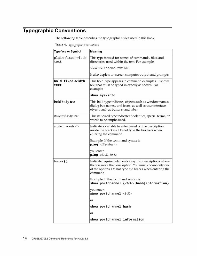
Typographic ConventionsThe following table describes the typographic styles used in this book.
Table 1. Typographic Conventions
Typeface or Symbol Meaning
plain fixed-width text
This type is used for names of commands, files, and directories used within the text. For example:
View the readme.txt file.
It also depicts on-screen computer output and prompts.
bold fixed-width text
This bold type appears in command examples. It shows text that must be typed in exactly as shown. For example:
show sys-info
bold body text This bold type indicates objects such as window names, dialog box names, and icons, as well as user interface objects such as buttons, and tabs.
italicized body text This italicized type indicates book titles, special terms, or words to be emphasized.
angle brackets < > Indicate a variable to enter based on the description inside the brackets. Do not type the brackets when entering the command.
Example: If the command syntax isping <IP address>
you enterping 192.32.10.12
braces {} Indicate required elements in syntax descriptions where there is more than one option. You must choose only one of the options. Do not type the braces when entering the command.
Example: If the command syntax isshow portchannel {<1-32>|hash|information}
you enter:show portchannel <1-32>
or
show portchannel hash
or
show portchannel information
© Copyright Lenovo 2015 Preface 15
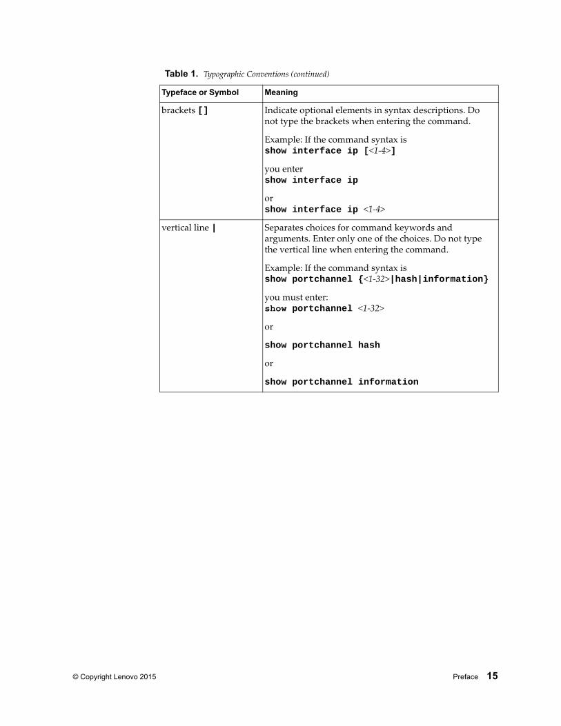
brackets [] Indicate optional elements in syntax descriptions. Do not type the brackets when entering the command.
Example: If the command syntax isshow interface ip [<1-4>]
you entershow interface ip
orshow interface ip <1-4>
vertical line | Separates choices for command keywords and arguments. Enter only one of the choices. Do not type the vertical line when entering the command.
Example: If the command syntax isshow portchannel {<1-32>|hash|information}
you must enter:show portchannel <1-32>
or
show portchannel hash
or
show portchannel information
Table 1. Typographic Conventions (continued)
Typeface or Symbol Meaning

16 G7028/G7052 Command Reference for N/OS 8.1
© Copyright Lenovo 2015 17
Chapter 1. ISCLI Basics
Your RackSwitch G7028/G7052 is ready to perform basic switching functions right out of the box. Some of the more advanced features, however, require some administrative configuration before they can be used effectively.
This guide describes the individual ISCLI commands available for the G7028/G7052.
The ISCLI provides a direct method for collecting switch information and performing switch configuration. Using a basic terminal, the ISCLI allows you to view information and statistics about the switch, and to perform any necessary configuration.
This chapter explains how to access the IS Command Line Interface (ISCLI) for the switch.
18 G7028/G7052 Command Reference for N/OS 8.1
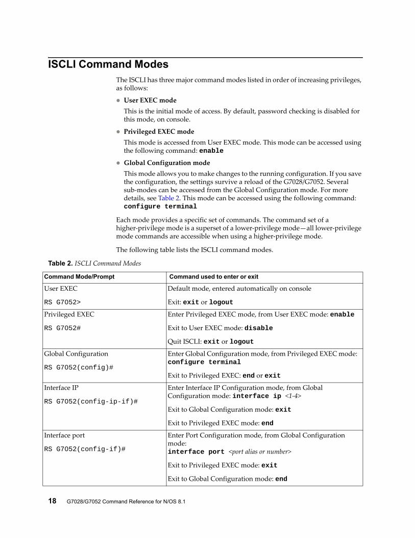
ISCLI Command Modes The ISCLI has three major command modes listed in order of increasing privileges, as follows:
User EXEC modeThis is the initial mode of access. By default, password checking is disabled for this mode, on console.
Privileged EXEC modeThis mode is accessed from User EXEC mode. This mode can be accessed using the following command: enable
Global Configuration modeThis mode allows you to make changes to the running configuration. If you save the configuration, the settings survive a reload of the G7028/G7052. Several sub-modes can be accessed from the Global Configuration mode. For more details, see Table 2. This mode can be accessed using the following command: configure terminal
Each mode provides a specific set of commands. The command set of a higher-privilege mode is a superset of a lower-privilege mode—all lower-privilege mode commands are accessible when using a higher-privilege mode.
The following table lists the ISCLI command modes.
Table 2. ISCLI Command Modes
Command Mode/Prompt Command used to enter or exit
User EXEC
RS G7052>
Default mode, entered automatically on console
Exit: exit or logout
Privileged EXEC
RS G7052#
Enter Privileged EXEC mode, from User EXEC mode: enable
Exit to User EXEC mode: disable
Quit ISCLI: exit or logout
Global Configuration
RS G7052(config)#
Enter Global Configuration mode, from Privileged EXEC mode: configure terminal
Exit to Privileged EXEC: end or exit
Interface IP
RS G7052(config-ip-if)#
Enter Interface IP Configuration mode, from Global Configuration mode: interface ip <1-4>
Exit to Global Configuration mode: exit
Exit to Privileged EXEC mode: end
Interface port
RS G7052(config-if)#
Enter Port Configuration mode, from Global Configuration mode:interface port <port alias or number>
Exit to Privileged EXEC mode: exit
Exit to Global Configuration mode: end
© Copyright Lenovo 2015 Chapter 1: ISCLI Basics 19
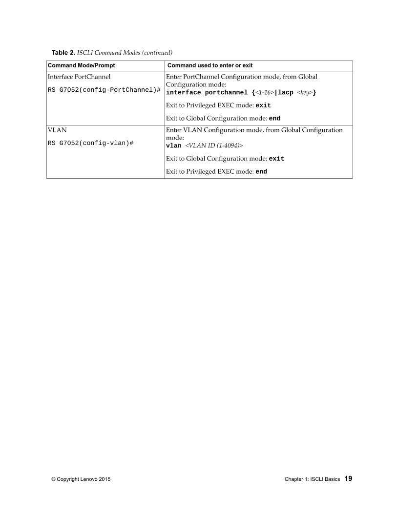
Interface PortChannel
RS G7052(config-PortChannel)#
Enter PortChannel Configuration mode, from Global Configuration mode:interface portchannel {<1-16>|lacp <key>}
Exit to Privileged EXEC mode: exit
Exit to Global Configuration mode: end
VLAN
RS G7052(config-vlan)#
Enter VLAN Configuration mode, from Global Configuration mode:vlan <VLAN ID (1-4094)>
Exit to Global Configuration mode: exit
Exit to Privileged EXEC mode: end
Table 2. ISCLI Command Modes (continued)
Command Mode/Prompt Command used to enter or exit
20 G7028/G7052 Command Reference for N/OS 8.1
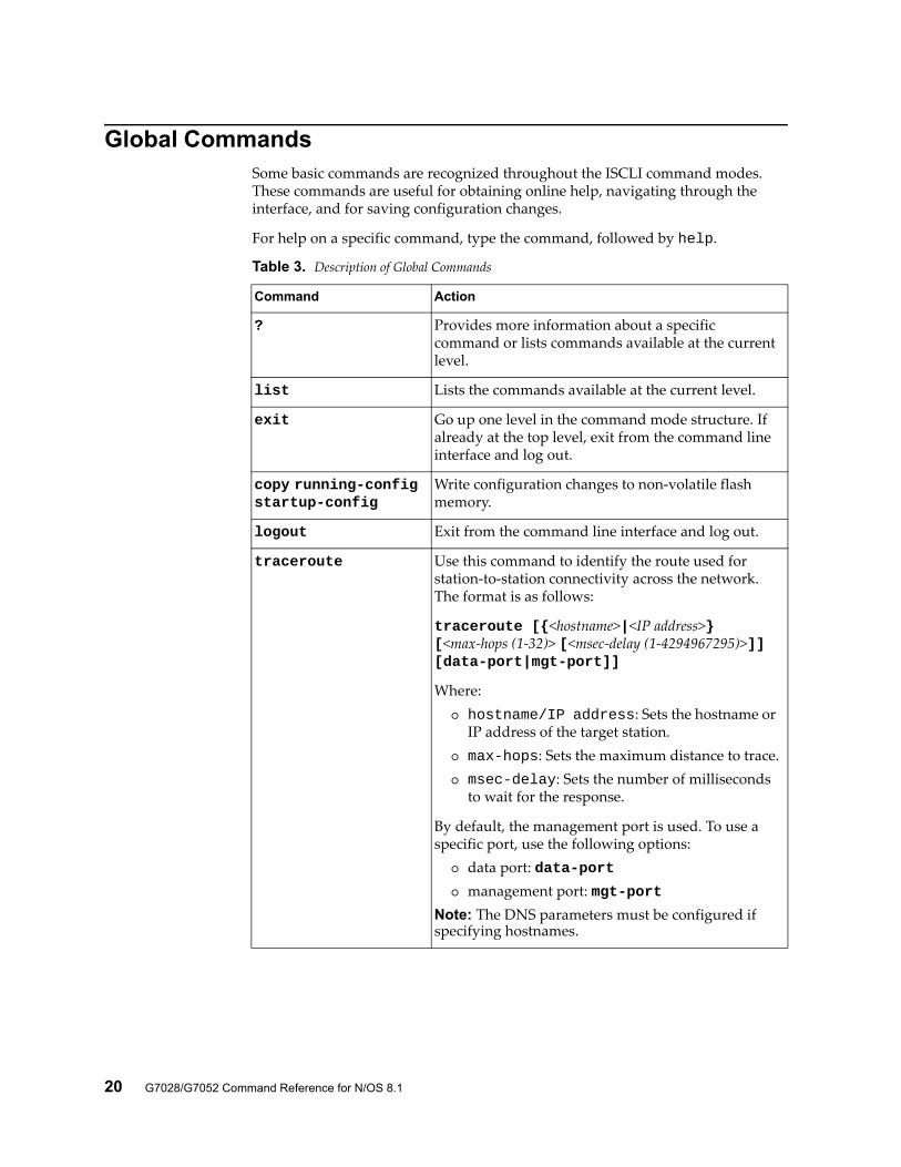
Global CommandsSome basic commands are recognized throughout the ISCLI command modes. These commands are useful for obtaining online help, navigating through the interface, and for saving configuration changes.
For help on a specific command, type the command, followed by help.
Table 3. Description of Global Commands
Command Action
? Provides more information about a specific command or lists commands available at the current level.
list Lists the commands available at the current level.
exit Go up one level in the command mode structure. If already at the top level, exit from the command line interface and log out.
copy running-config startup-config
Write configuration changes to non-volatile flash memory.
logout Exit from the command line interface and log out.
traceroute Use this command to identify the route used for station-to-station connectivity across the network. The format is as follows:
traceroute [{<hostname>|<IP address>} [<max-hops (1-32)> [<msec-delay (1-4294967295)>]] [data-port|mgt-port]]
Where: hostname/IP address: Sets the hostname or
IP address of the target station. max-hops: Sets the maximum distance to trace. msec-delay: Sets the number of milliseconds
to wait for the response.
By default, the management port is used. To use a specific port, use the following options:
data port: data-port management port: mgt-port
Note: The DNS parameters must be configured if specifying hostnames.
© Copyright Lenovo 2015 Chapter 1: ISCLI Basics 21
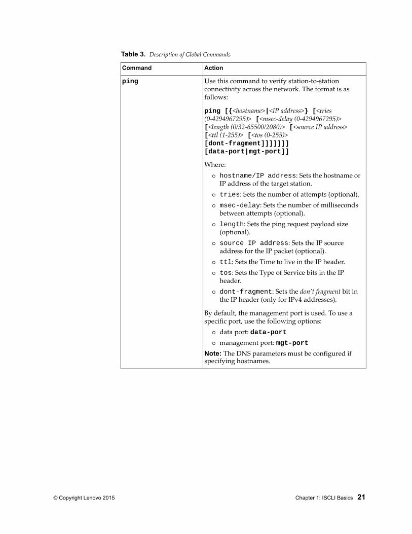
ping Use this command to verify station-to-station connectivity across the network. The format is as follows:
ping [{<hostname>|<IP address>} [<tries (0-4294967295)> [<msec-delay (0-4294967295)> [<length (0/32-65500/2080)> [<source IP address> [<ttl (1-255)> [<tos (0-255)> [dont-fragment]]]]]]] [data-port|mgt-port]]
Where: hostname/IP address: Sets the hostname or
IP address of the target station. tries: Sets the number of attempts (optional). msec-delay: Sets the number of milliseconds
between attempts (optional). length: Sets the ping request payload size
(optional). source IP address: Sets the IP source
address for the IP packet (optional). ttl: Sets the Time to live in the IP header. tos: Sets the Type of Service bits in the IP
header. dont-fragment: Sets the don’t fragment bit in
the IP header (only for IPv4 addresses).
By default, the management port is used. To use a specific port, use the following options:
data port: data-port management port: mgt-port
Note: The DNS parameters must be configured if specifying hostnames.
Table 3. Description of Global Commands
Command Action
22 G7028/G7052 Command Reference for N/OS 8.1
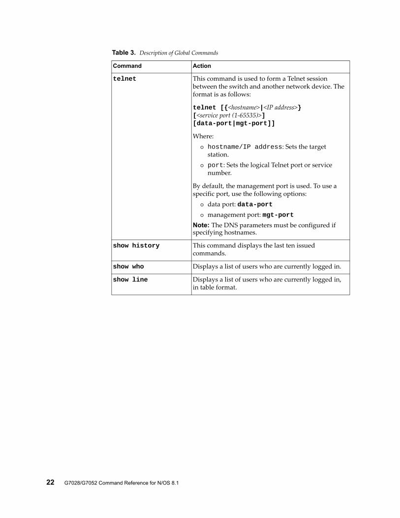
telnet This command is used to form a Telnet session between the switch and another network device. The format is as follows:
telnet [{<hostname>|<IP address>}[<service port (1-65535)>] [data-port|mgt-port]]
Where: hostname/IP address: Sets the target
station. port: Sets the logical Telnet port or service
number.
By default, the management port is used. To use a specific port, use the following options:
data port: data-port management port: mgt-port
Note: The DNS parameters must be configured if specifying hostnames.
show history This command displays the last ten issued commands.
show who Displays a list of users who are currently logged in.
show line Displays a list of users who are currently logged in, in table format.
Table 3. Description of Global Commands
Command Action
© Copyright Lenovo 2015 Chapter 1: ISCLI Basics 23
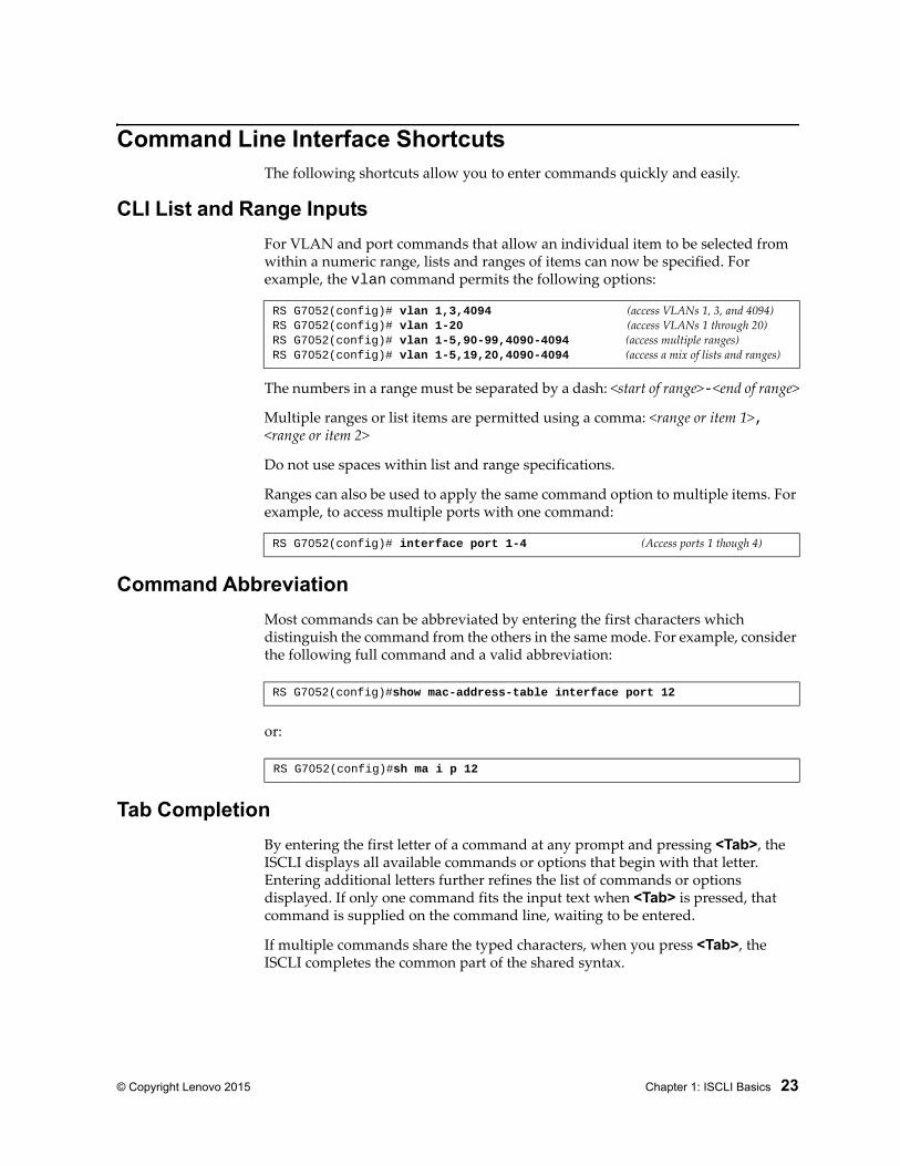
Command Line Interface ShortcutsThe following shortcuts allow you to enter commands quickly and easily.
CLI List and Range Inputs
For VLAN and port commands that allow an individual item to be selected from within a numeric range, lists and ranges of items can now be specified. For example, the vlan command permits the following options:
The numbers in a range must be separated by a dash: <start of range>-<end of range>
Multiple ranges or list items are permitted using a comma: <range or item 1>, <range or item 2>
Do not use spaces within list and range specifications.
Ranges can also be used to apply the same command option to multiple items. For example, to access multiple ports with one command:
Command Abbreviation
Most commands can be abbreviated by entering the first characters which distinguish the command from the others in the same mode. For example, consider the following full command and a valid abbreviation:
or:
Tab Completion
By entering the first letter of a command at any prompt and pressing <Tab>, the ISCLI displays all available commands or options that begin with that letter. Entering additional letters further refines the list of commands or options displayed. If only one command fits the input text when <Tab> is pressed, that command is supplied on the command line, waiting to be entered.
If multiple commands share the typed characters, when you press <Tab>, the ISCLI completes the common part of the shared syntax.
RS G7052(config)# vlan 1,3,4094 (access VLANs 1, 3, and 4094)RS G7052(config)# vlan 1-20 (access VLANs 1 through 20)RS G7052(config)# vlan 1-5,90-99,4090-4094 (access multiple ranges)RS G7052(config)# vlan 1-5,19,20,4090-4094 (access a mix of lists and ranges)
RS G7052(config)# interface port 1-4 (Access ports 1 though 4)
RS G7052(config)#show mac-address-table interface port 12
RS G7052(config)#sh ma i p 12
24 G7028/G7052 Command Reference for N/OS 8.1
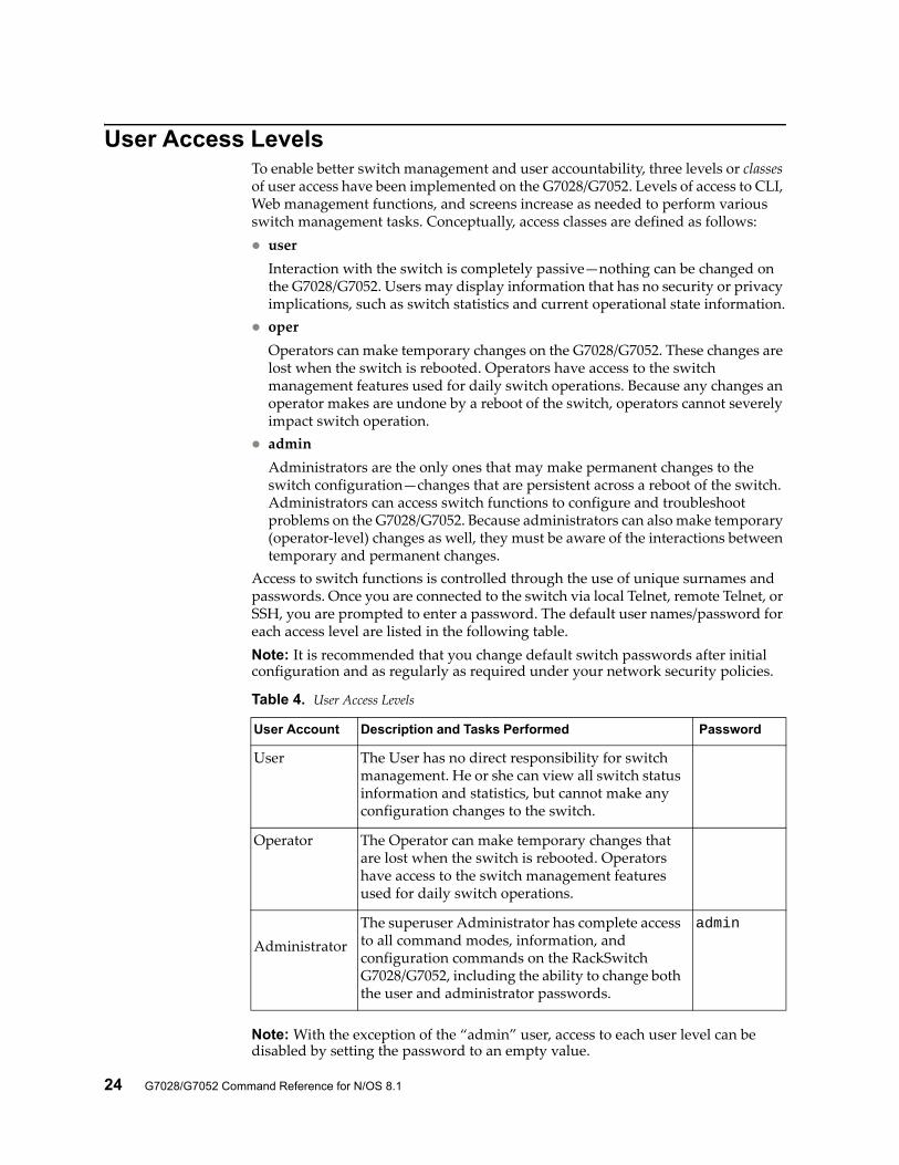
User Access LevelsTo enable better switch management and user accountability, three levels or classes of user access have been implemented on the G7028/G7052. Levels of access to CLI, Web management functions, and screens increase as needed to perform various switch management tasks. Conceptually, access classes are defined as follows: user
Interaction with the switch is completely passive—nothing can be changed on the G7028/G7052. Users may display information that has no security or privacy implications, such as switch statistics and current operational state information.
operOperators can make temporary changes on the G7028/G7052. These changes are lost when the switch is rebooted. Operators have access to the switch management features used for daily switch operations. Because any changes an operator makes are undone by a reboot of the switch, operators cannot severely impact switch operation.
adminAdministrators are the only ones that may make permanent changes to the switch configuration—changes that are persistent across a reboot of the switch. Administrators can access switch functions to configure and troubleshoot problems on the G7028/G7052. Because administrators can also make temporary (operator-level) changes as well, they must be aware of the interactions between temporary and permanent changes.
Access to switch functions is controlled through the use of unique surnames and passwords. Once you are connected to the switch via local Telnet, remote Telnet, or SSH, you are prompted to enter a password. The default user names/password for each access level are listed in the following table.Note: It is recommended that you change default switch passwords after initial configuration and as regularly as required under your network security policies.
Note: With the exception of the “admin” user, access to each user level can be disabled by setting the password to an empty value.
Table 4. User Access Levels
User Account Description and Tasks Performed Password
User The User has no direct responsibility for switch management. He or she can view all switch status information and statistics, but cannot make any configuration changes to the switch.
Operator The Operator can make temporary changes that are lost when the switch is rebooted. Operators have access to the switch management features used for daily switch operations.
Administrator
The superuser Administrator has complete access to all command modes, information, and configuration commands on the RackSwitch G7028/G7052, including the ability to change both the user and administrator passwords.
admin

© Copyright Lenovo 2015 Chapter 1: ISCLI Basics 25
Idle TimeoutBy default, the switch will disconnect your Telnet session after ten minutes of inactivity. This function is controlled by the following command, which can be set from 1 to 60 minutes, or disabled when set to 0:
system idle <0-60>
Command mode: Global Configuration

26 G7028/G7052 Command Reference for N/OS 8.1
© Copyright Lenovo 2015 27
Chapter 2. Information Commands
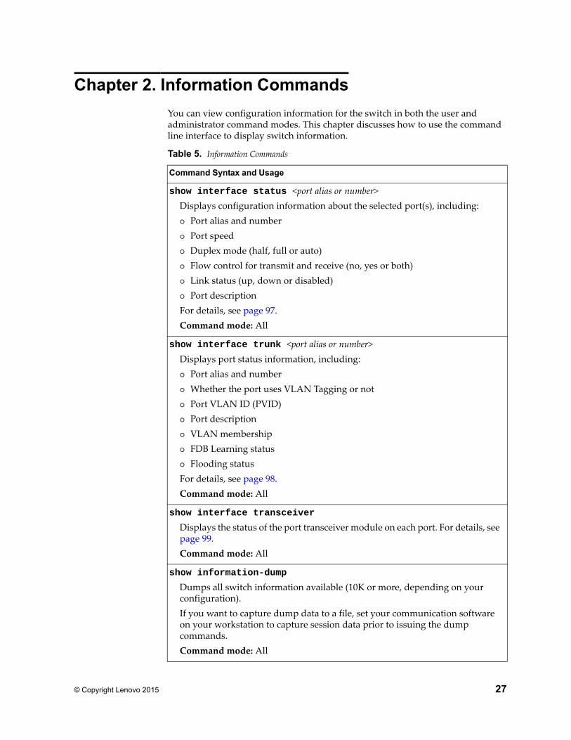
You can view configuration information for the switch in both the user and administrator command modes. This chapter discusses how to use the command line interface to display switch information.
Table 5. Information Commands
Command Syntax and Usage
show interface status <port alias or number>Displays configuration information about the selected port(s), including: Port alias and number Port speed Duplex mode (half, full or auto) Flow control for transmit and receive (no, yes or both) Link status (up, down or disabled) Port descriptionFor details, see page 97.Command mode: All
show interface trunk <port alias or number>Displays port status information, including: Port alias and number Whether the port uses VLAN Tagging or not Port VLAN ID (PVID) Port description VLAN membership FDB Learning status Flooding statusFor details, see page 98.Command mode: All
show interface transceiver
Displays the status of the port transceiver module on each port. For details, see page 99.Command mode: All
show information-dump
Dumps all switch information available (10K or more, depending on your configuration).If you want to capture dump data to a file, set your communication software on your workstation to capture session data prior to issuing the dump commands.Command mode: All
28 G7028/G7052 Command Reference for N/OS 8.1
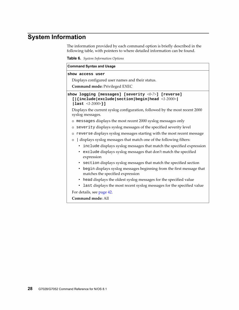
System InformationThe information provided by each command option is briefly described in the following table, with pointers to where detailed information can be found.
Table 6. System Information Options
Command Syntax and Usage
show access user
Displays configured user names and their status.Command mode: Privileged EXEC
show logging [messages] [severity <0-7>] [reverse] [|{include|exclude|section|begin|head <1-2000>| |last <1-2000>}]
Displays the current syslog configuration, followed by the most recent 2000 syslog messages. messages displays the most recent 2000 syslog messages only severity displays syslog messages of the specified severity level reverse displays syslog messages starting with the most recent message | displays syslog messages that match one of the following filters:
• include displays syslog messages that match the specified expression• exclude displays syslog messages that don’t match the specified
expression• section displays syslog messages that match the specified section• begin displays syslog messages beginning from the first message that
matches the specified expression• head displays the oldest syslog messages for the specified value• last displays the most recent syslog messages for the specified value
For details, see page 42.Command mode: All
© Copyright Lenovo 2015 Chapter 2: Information Commands 29
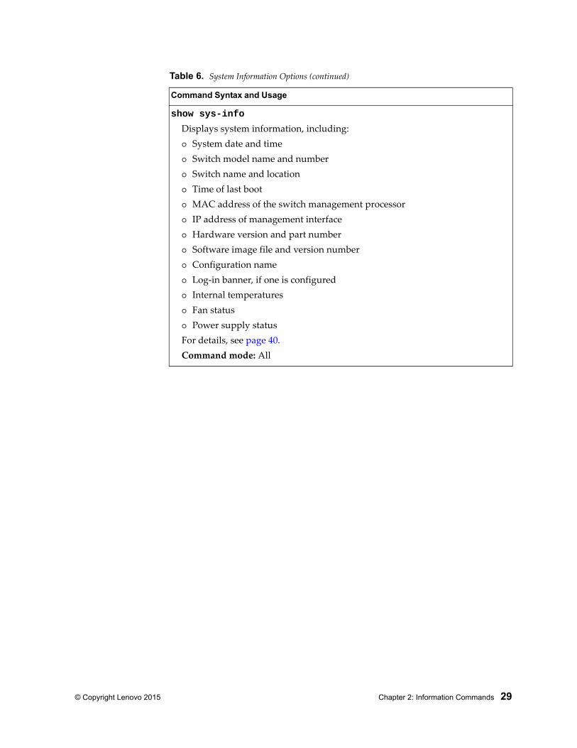
show sys-info
Displays system information, including: System date and time Switch model name and number Switch name and location Time of last boot MAC address of the switch management processor IP address of management interface Hardware version and part number Software image file and version number Configuration name Log-in banner, if one is configured Internal temperatures Fan status Power supply statusFor details, see page 40.Command mode: All
Table 6. System Information Options (continued)
Command Syntax and Usage
30 G7028/G7052 Command Reference for N/OS 8.1
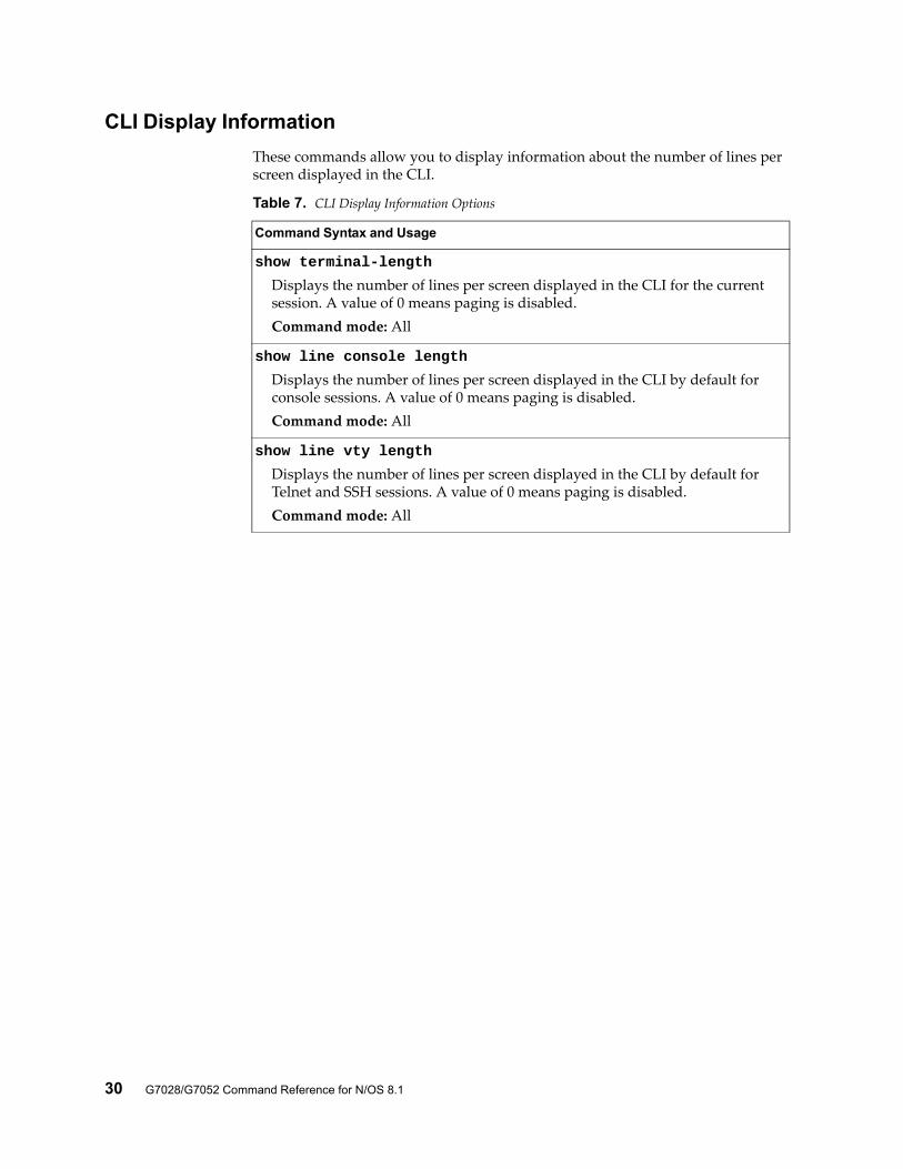
CLI Display Information
These commands allow you to display information about the number of lines per screen displayed in the CLI.
Table 7. CLI Display Information Options
Command Syntax and Usage
show terminal-length
Displays the number of lines per screen displayed in the CLI for the current session. A value of 0 means paging is disabled.Command mode: All
show line console length
Displays the number of lines per screen displayed in the CLI by default for console sessions. A value of 0 means paging is disabled.Command mode: All
show line vty length
Displays the number of lines per screen displayed in the CLI by default for Telnet and SSH sessions. A value of 0 means paging is disabled.Command mode: All
© Copyright Lenovo 2015 Chapter 2: Information Commands 31
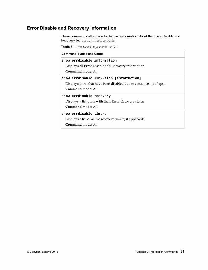
Error Disable and Recovery Information
These commands allow you to display information about the Error Disable and Recovery feature for interface ports.
Table 8. Error Disable Information Options
Command Syntax and Usage
show errdisable information
Displays all Error Disable and Recovery information.Command mode: All
show errdisable link-flap [information]
Displays ports that have been disabled due to excessive link flaps.Command mode: All
show errdisable recovery
Displays a list ports with their Error Recovery status.Command mode: All
show errdisable timers
Displays a list of active recovery timers, if applicable.Command mode: All
32 G7028/G7052 Command Reference for N/OS 8.1
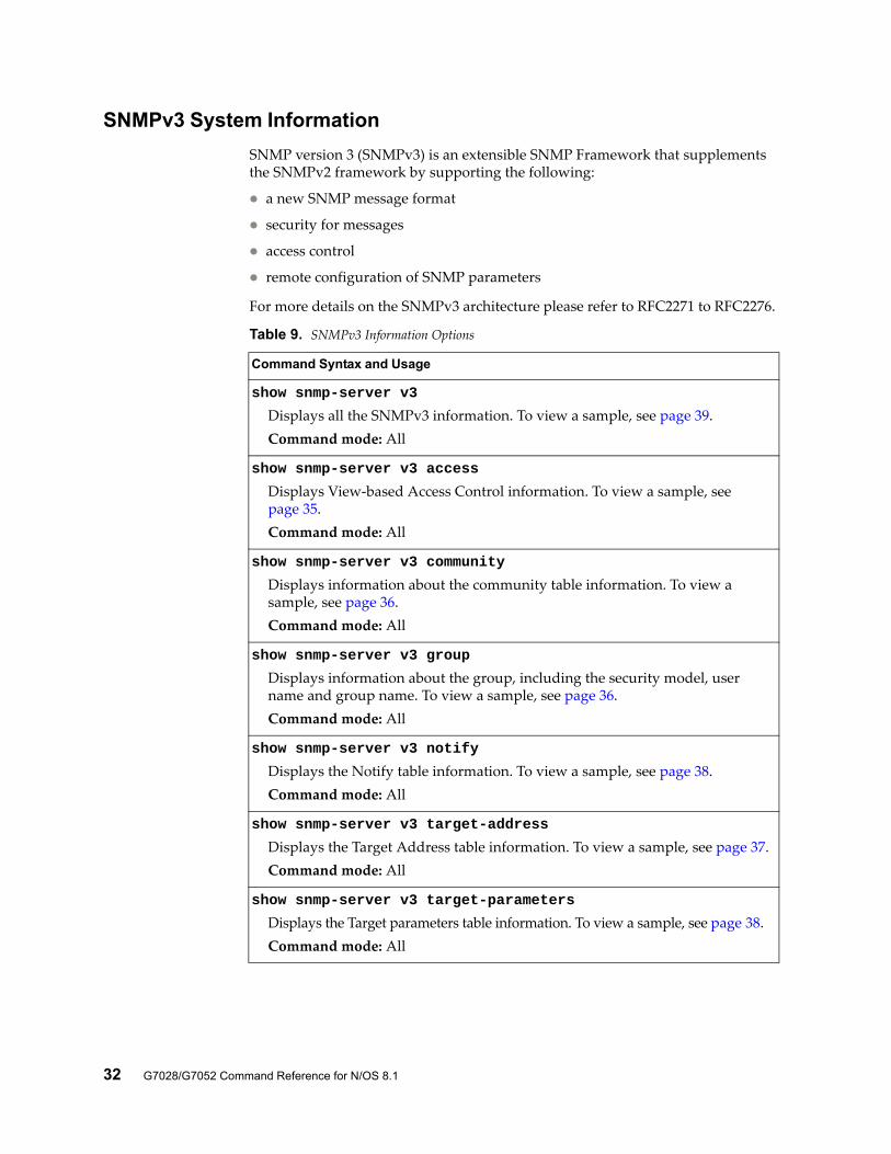
SNMPv3 System Information
SNMP version 3 (SNMPv3) is an extensible SNMP Framework that supplements the SNMPv2 framework by supporting the following:
a new SNMP message format
security for messages
access control
remote configuration of SNMP parameters
For more details on the SNMPv3 architecture please refer to RFC2271 to RFC2276.
Table 9. SNMPv3 Information Options
Command Syntax and Usage
show snmp-server v3
Displays all the SNMPv3 information. To view a sample, see page 39.Command mode: All
show snmp-server v3 access
Displays View-based Access Control information. To view a sample, see page 35.Command mode: All
show snmp-server v3 community
Displays information about the community table information. To view a sample, see page 36.Command mode: All
show snmp-server v3 group
Displays information about the group, including the security model, user name and group name. To view a sample, see page 36.Command mode: All
show snmp-server v3 notify
Displays the Notify table information. To view a sample, see page 38.Command mode: All
show snmp-server v3 target-address
Displays the Target Address table information. To view a sample, see page 37.Command mode: All
show snmp-server v3 target-parameters
Displays the Target parameters table information. To view a sample, see page 38.Command mode: All
© Copyright Lenovo 2015 Chapter 2: Information Commands 33
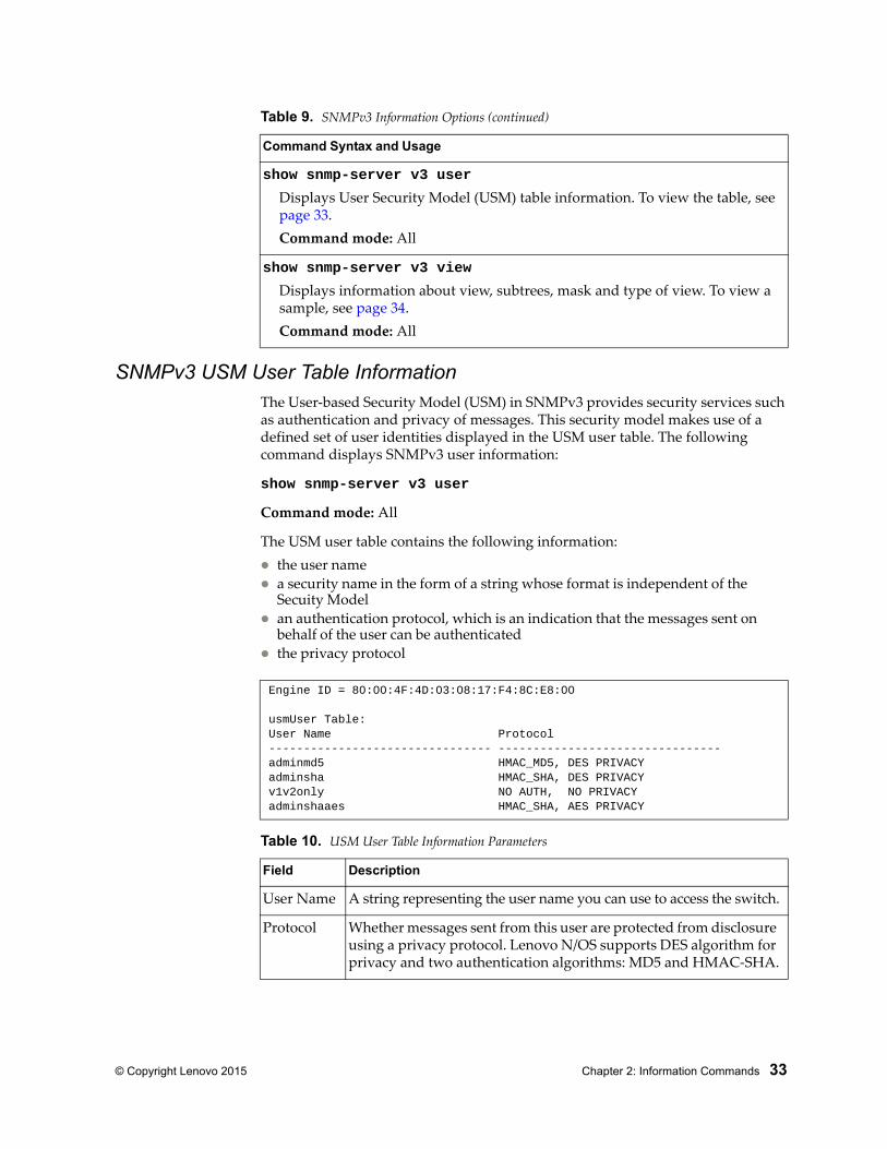
SNMPv3 USM User Table InformationThe User-based Security Model (USM) in SNMPv3 provides security services such as authentication and privacy of messages. This security model makes use of a defined set of user identities displayed in the USM user table. The following command displays SNMPv3 user information:
show snmp-server v3 user
Command mode: All
The USM user table contains the following information: the user name a security name in the form of a string whose format is independent of the
Secuity Model an authentication protocol, which is an indication that the messages sent on
behalf of the user can be authenticated the privacy protocol
show snmp-server v3 user
Displays User Security Model (USM) table information. To view the table, see page 33.Command mode: All
show snmp-server v3 view
Displays information about view, subtrees, mask and type of view. To view a sample, see page 34.Command mode: All
Table 9. SNMPv3 Information Options (continued)
Command Syntax and Usage
Engine ID = 80:00:4F:4D:03:08:17:F4:8C:E8:00
usmUser Table:User Name Protocol-------------------------------- --------------------------------adminmd5 HMAC_MD5, DES PRIVACYadminsha HMAC_SHA, DES PRIVACYv1v2only NO AUTH, NO PRIVACYadminshaaes HMAC_SHA, AES PRIVACY
Table 10. USM User Table Information Parameters
Field Description
User Name A string representing the user name you can use to access the switch.
Protocol Whether messages sent from this user are protected from disclosure using a privacy protocol. Lenovo N/OS supports DES algorithm for privacy and two authentication algorithms: MD5 and HMAC-SHA.
34 G7028/G7052 Command Reference for N/OS 8.1
SNMPv3 View Table Information
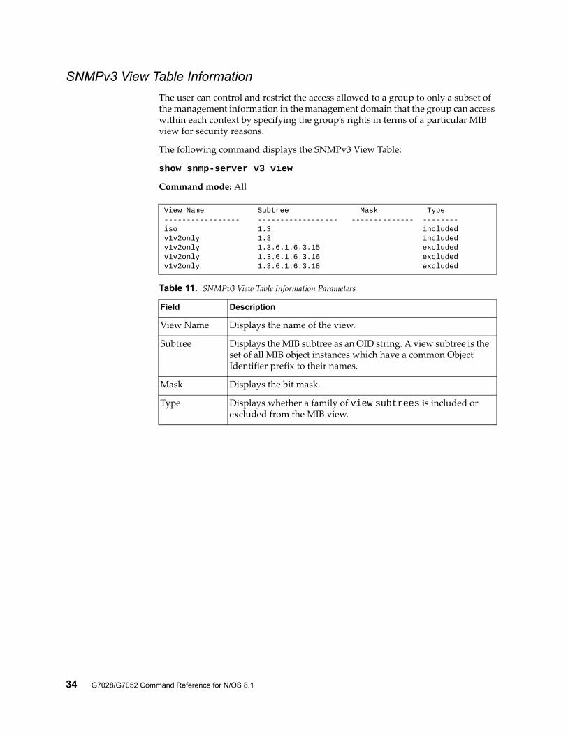
The user can control and restrict the access allowed to a group to only a subset of the management information in the management domain that the group can access within each context by specifying the group’s rights in terms of a particular MIB view for security reasons.
The following command displays the SNMPv3 View Table:
show snmp-server v3 view
Command mode: All
View Name Subtree Mask Type----------------- ------------------ -------------- --------iso 1.3 includedv1v2only 1.3 includedv1v2only 1.3.6.1.6.3.15 excludedv1v2only 1.3.6.1.6.3.16 excludedv1v2only 1.3.6.1.6.3.18 excluded
Table 11. SNMPv3 View Table Information Parameters
Field Description
View Name Displays the name of the view.
Subtree Displays the MIB subtree as an OID string. A view subtree is the set of all MIB object instances which have a common Object Identifier prefix to their names.
Mask Displays the bit mask.
Type Displays whether a family of view subtrees is included or excluded from the MIB view.
© Copyright Lenovo 2015 Chapter 2: Information Commands 35
SNMPv3 Access Table Information
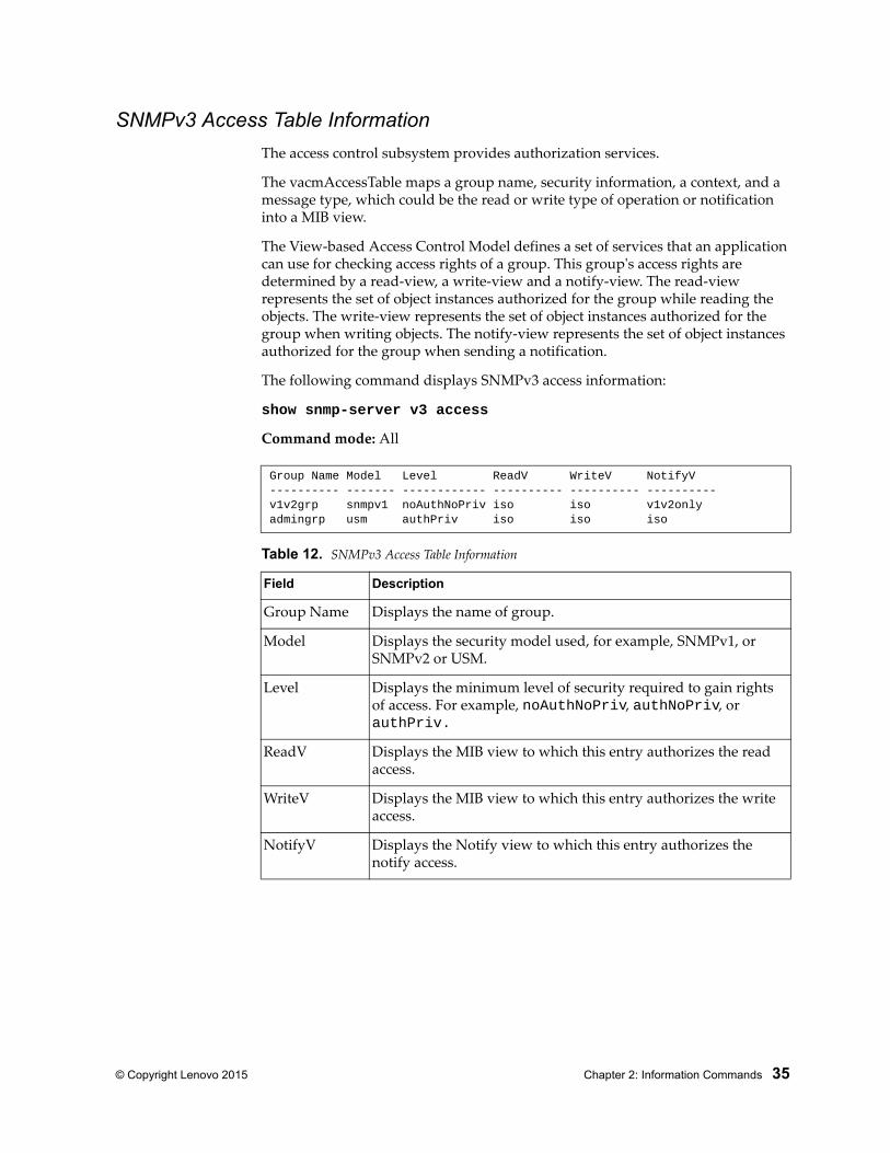
The access control subsystem provides authorization services.
The vacmAccessTable maps a group name, security information, a context, and a message type, which could be the read or write type of operation or notification into a MIB view.
The View-based Access Control Model defines a set of services that an application can use for checking access rights of a group. This group's access rights are determined by a read-view, a write-view and a notify-view. The read-view represents the set of object instances authorized for the group while reading the objects. The write-view represents the set of object instances authorized for the group when writing objects. The notify-view represents the set of object instances authorized for the group when sending a notification.
The following command displays SNMPv3 access information:
show snmp-server v3 access
Command mode: All
Group Name Model Level ReadV WriteV NotifyV---------- ------- ------------ ---------- ---------- ----------v1v2grp snmpv1 noAuthNoPriv iso iso v1v2onlyadmingrp usm authPriv iso iso iso
Table 12. SNMPv3 Access Table Information
Field Description
Group Name Displays the name of group.
Model Displays the security model used, for example, SNMPv1, or SNMPv2 or USM.
Level Displays the minimum level of security required to gain rights of access. For example, noAuthNoPriv, authNoPriv, or authPriv.
ReadV Displays the MIB view to which this entry authorizes the read access.
WriteV Displays the MIB view to which this entry authorizes the write access.
NotifyV Displays the Notify view to which this entry authorizes the notify access.
36 G7028/G7052 Command Reference for N/OS 8.1
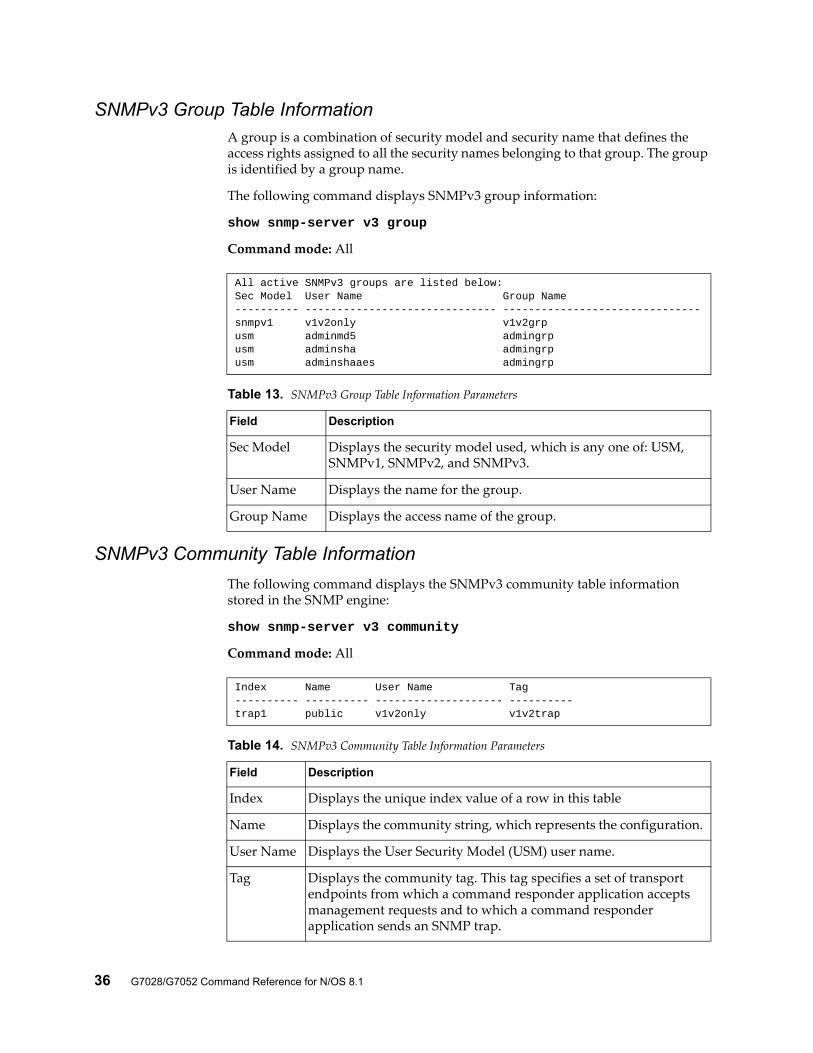
SNMPv3 Group Table InformationA group is a combination of security model and security name that defines the access rights assigned to all the security names belonging to that group. The group is identified by a group name.
The following command displays SNMPv3 group information:
show snmp-server v3 group
Command mode: All
SNMPv3 Community Table Information
The following command displays the SNMPv3 community table information stored in the SNMP engine:
show snmp-server v3 community
Command mode: All
All active SNMPv3 groups are listed below:Sec Model User Name Group Name---------- ------------------------------ -------------------------------snmpv1 v1v2only v1v2grpusm adminmd5 admingrpusm adminsha admingrpusm adminshaaes admingrp
Table 13. SNMPv3 Group Table Information Parameters
Field Description
Sec Model Displays the security model used, which is any one of: USM, SNMPv1, SNMPv2, and SNMPv3.
User Name Displays the name for the group.
Group Name Displays the access name of the group.
Index Name User Name Tag---------- ---------- -------------------- ----------trap1 public v1v2only v1v2trap
Table 14. SNMPv3 Community Table Information Parameters
Field Description
Index Displays the unique index value of a row in this table
Name Displays the community string, which represents the configuration.
User Name Displays the User Security Model (USM) user name.
Tag Displays the community tag. This tag specifies a set of transport endpoints from which a command responder application accepts management requests and to which a command responder application sends an SNMP trap.
© Copyright Lenovo 2015 Chapter 2: Information Commands 37
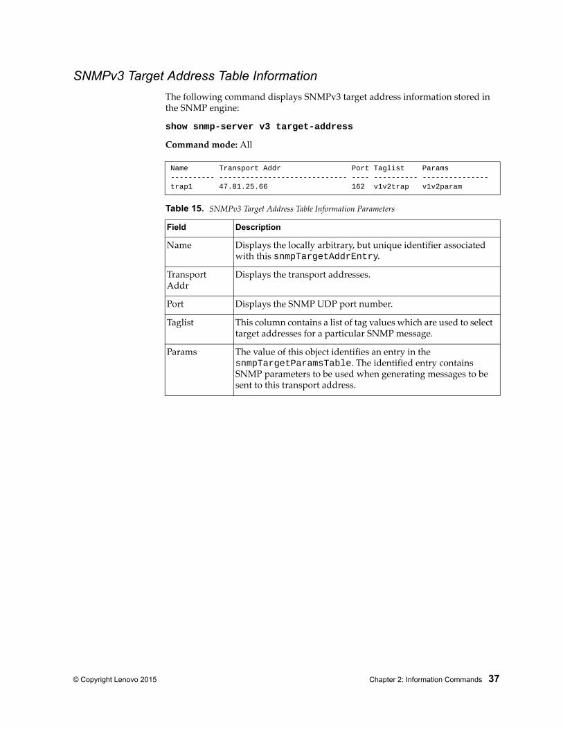
SNMPv3 Target Address Table Information
The following command displays SNMPv3 target address information stored in the SNMP engine:
show snmp-server v3 target-address
Command mode: All
Name Transport Addr Port Taglist Params---------- ----------------------------- ---- ---------- ---------------trap1 47.81.25.66 162 v1v2trap v1v2param
Table 15. SNMPv3 Target Address Table Information Parameters
Field Description
Name Displays the locally arbitrary, but unique identifier associated with this snmpTargetAddrEntry.
Transport Addr
Displays the transport addresses.
Port Displays the SNMP UDP port number.
Taglist This column contains a list of tag values which are used to select target addresses for a particular SNMP message.
Params The value of this object identifies an entry in the snmpTargetParamsTable. The identified entry contains SNMP parameters to be used when generating messages to be sent to this transport address.
38 G7028/G7052 Command Reference for N/OS 8.1
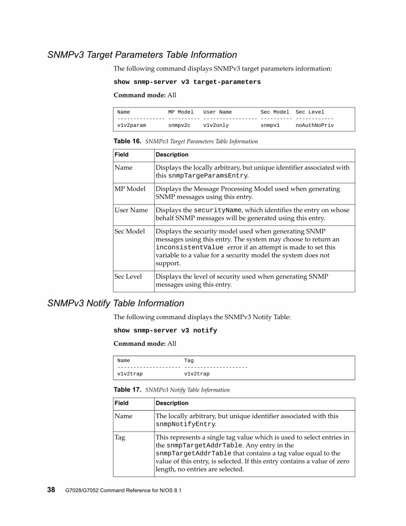
SNMPv3 Target Parameters Table InformationThe following command displays SNMPv3 target parameters information:
show snmp-server v3 target-parameters
Command mode: All
SNMPv3 Notify Table InformationThe following command displays the SNMPv3 Notify Table:
show snmp-server v3 notify
Command mode: All
Name MP Model User Name Sec Model Sec Level--------------- ---------- ----------------- ---------- ------------v1v2param snmpv2c v1v2only snmpv1 noAuthNoPriv
Table 16. SNMPv3 Target Parameters Table Information
Field Description
Name Displays the locally arbitrary, but unique identifier associated with this snmpTargeParamsEntry.
MP Model Displays the Message Processing Model used when generating SNMP messages using this entry.
User Name Displays the securityName, which identifies the entry on whose behalf SNMP messages will be generated using this entry.
Sec Model Displays the security model used when generating SNMP messages using this entry. The system may choose to return an inconsistentValue error if an attempt is made to set this variable to a value for a security model the system does not support.
Sec Level Displays the level of security used when generating SNMP messages using this entry.
Name Tag-------------------- --------------------v1v2trap v1v2trap
Table 17. SNMPv3 Notify Table Information
Field Description
Name The locally arbitrary, but unique identifier associated with this snmpNotifyEntry.
Tag This represents a single tag value which is used to select entries in the snmpTargetAddrTable. Any entry in the snmpTargetAddrTable that contains a tag value equal to the value of this entry, is selected. If this entry contains a value of zero length, no entries are selected.
© Copyright Lenovo 2015 Chapter 2: Information Commands 39
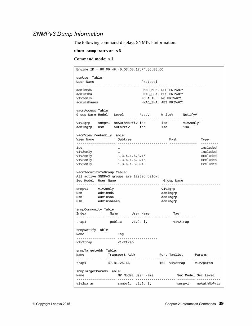
SNMPv3 Dump InformationThe following command displays SNMPv3 information:
show snmp-server v3
Command mode: All
Engine ID = 80:00:4F:4D:03:08:17:F4:8C:E8:00
usmUser Table:User Name Protocol-------------------------------- --------------------------------adminmd5 HMAC_MD5, DES PRIVACYadminsha HMAC_SHA, DES PRIVACYv1v2only NO AUTH, NO PRIVACYadminshaaes HMAC_SHA, AES PRIVACY
vacmAccess Table:Group Name Model Level ReadV WriteV NotifyV---------- ------- ------------ ---------- ---------- ----------v1v2grp snmpv1 noAuthNoPriv iso iso v1v2onlyadmingrp usm authPriv iso iso iso
vacmViewTreeFamily Table:View Name Subtree Mask Type-------------------- ------------------------- -------------- ---------iso 1 includedv1v2only 1 includedv1v2only 1.3.6.1.6.3.15 excludedv1v2only 1.3.6.1.6.3.16 excludedv1v2only 1.3.6.1.6.3.18 excluded
vacmSecurityToGroup Table:All active SNMPv3 groups are listed below:Sec Model User Name Group Name---------- ------------------------------- ------------------------------snmpv1 v1v2only v1v2grpusm adminmd5 admingrpusm adminsha admingrpusm adminshaaes admingrp
snmpCommunity Table:Index Name User Name Tag---------------- ---------- -------------------- ------------trap1 public v1v2only v1v2trap
snmpNotify Table:Name Tag-------------------- --------------------v1v2trap v1v2trap
snmpTargetAddr Table:Name Transport Addr Port Taglist Params--------------- ------------------------- ---- ------------ -------------trap1 47.81.25.66 162 v1v2trap v1v2param
snmpTargetParams Table:Name MP Model User Name Sec Model Sec Level-------------------- -------- -------------------- --------- ------------v1v2param snmpv2c v1v2only snmpv1 noAuthNoPriv
40 G7028/G7052 Command Reference for N/OS 8.1
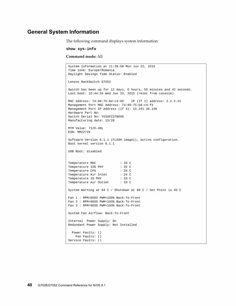
General System Information
The following command displays system information:
show sys-info
Command mode: All
System Information at 11:39:58 Mon Jun 22, 2015Time zone: Europe/RomaniaDaylight Savings Time Status: Enabled
Lenovo RackSwitch G7052
Switch has been up for 12 days, 0 hours, 55 minutes and 42 seconds.Last boot: 10:44:34 Wed Jun 10, 2015 (reset from console)
MAC address: 74:99:75:bd:c4:00 IP (If 1) address: 2.2.2.21Management Port MAC Address: 74:99:75:bd:c4:feManagement Port IP Address (if 4): 10.241.36.146Hardware Part No: Switch Serial No: Y030PZ37B00GManufacturing date: 13/28
MTM Value: 7120-48LESN: MM22729
Software Version 8.1.1 (FLASH image1), active configuration.Boot kernel version 8.1.1
USB Boot: disabled
Temperature MAC : 33 CTemperature 10G PHY : 32 CTemperature CPU : 26 CTemperature Air Inlet : 24 C Temperature 1G PHY : 33 CTemperature Air Outlet : 33 C
System Warning at 64 C / Shutdown at 69 C / Set Point is 45 C
Fan 1 : RPM=9000 PWM=100% Back-To-FrontFan 2 : RPM=9000 PWM=100% Back-To-FrontFan 3 : RPM=9000 PWM=100% Back-To-Front
System Fan Airflow: Back-To-Front
Internal Power Supply: OnRedundant Power Supply: Not Installed
Power Faults: () Fan Faults: ()Service Faults: ()
© Copyright Lenovo 2015 Chapter 2: Information Commands 41
Note: The display of temperature will come up only if the temperature of any of the sensors exceeds the temperature threshold. There will be a warning from the software if any of the sensors exceeds this temperature threshold. The switch will shut down if the power supply overheats.
System information includes:
System date and time
Switch model
Switch name and location
Time of last boot
MAC address of the switch management processor
Software image file and version number, and configuration name.
IP address of the management interface
Part number
Log-in banner, if one is configured
Internal temperatures
Fan status
Power supply status
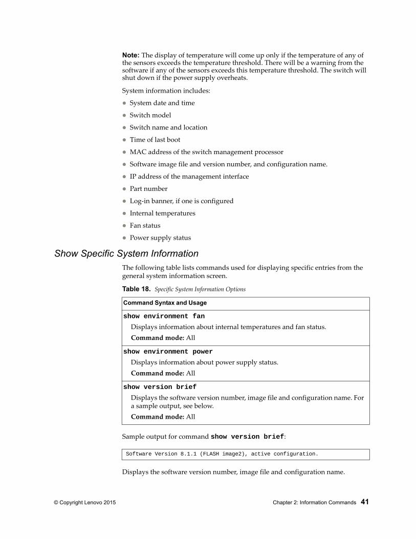
Show Specific System InformationThe following table lists commands used for displaying specific entries from the general system information screen.
Sample output for command show version brief:
Displays the software version number, image file and configuration name.
Table 18. Specific System Information Options
Command Syntax and Usage
show environment fan
Displays information about internal temperatures and fan status.Command mode: All
show environment power
Displays information about power supply status.Command mode: All
show version brief
Displays the software version number, image file and configuration name. For a sample output, see below.Command mode: All
Software Version 8.1.1 (FLASH image2), active configuration.
42 G7028/G7052 Command Reference for N/OS 8.1
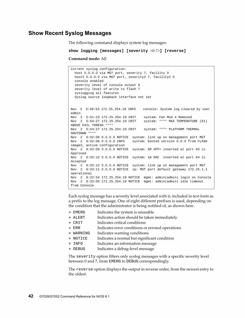
Show Recent Syslog Messages
The following command displays system log messages:
show logging [messages] [severity <0-7>] [reverse]
Command mode: All
Each syslog message has a severity level associated with it, included in text form as a prefix to the log message. One of eight different prefixes is used, depending on the condition that the administrator is being notified of, as shown here. EMERG Indicates the system is unusable ALERT Indicates action should be taken immediately CRIT Indicates critical conditions ERR Indicates error conditions or errored operations WARNING Indicates warning conditions NOTICE Indicates a normal but significant condition INFO Indicates an information message DEBUG Indicates a debug-level message
The severity option filters only syslog messages with a specific severity level between 0 and 7, from EMERG to DEBUG correspondingly.
The reverse option displays the output in reverse order, from the newest entry to the oldest.
Current syslog configuration: host 0.0.0.0 via MGT port, severity 7, facility 0 host2 0.0.0.0 via MGT port, severity2 7, facility2 0 console enabled severity level of console output 6 severity level of write to flash 7 syslogging all features Syslog source loopback interface not set
Nov 2 5:49:53 172.25.254.19 INFO console: System log cleared by user admin.Nov 2 5:51:23 172.25.254.19 CRIT system: Fan Mod 4 RemovedNov 2 5:54:27 172.25.254.19 CRIT system: **** MAX TEMPERATURE (61) ABOVE FAIL THRESH ****Nov 2 5:54:27 172.25.254.19 CRIT system: **** PLATFORM THERMAL SHUTDOWN ****Nov 2 6:02:06 0.0.0.0 NOTICE system: link up on management port MGTNov 2 6:02:06 0.0.0.0 INFO system: booted version 0.0.0 from FLASH image2, active configurationNov 2 6:02:09 0.0.0.0 NOTICE system: SR SFP+ inserted at port 63 is ApprovedNov 2 6:02:12 0.0.0.0 NOTICE system: 1m DAC inserted at port 64 is AcceptedNov 2 6:02:12 0.0.0.0 NOTICE system: link up on management port MGTNov 2 6:03:11 0.0.0.0 NOTICE ip: MGT port default gateway 172.25.1.1 operationalNov 2 6:22:54 172.25.254.19 NOTICE mgmt: admin(admin) login on ConsoleNov 2 6:33:00 172.25.254.19 NOTICE mgmt: admin(admin) idle timeout from Console
© Copyright Lenovo 2015 Chapter 2: Information Commands 43
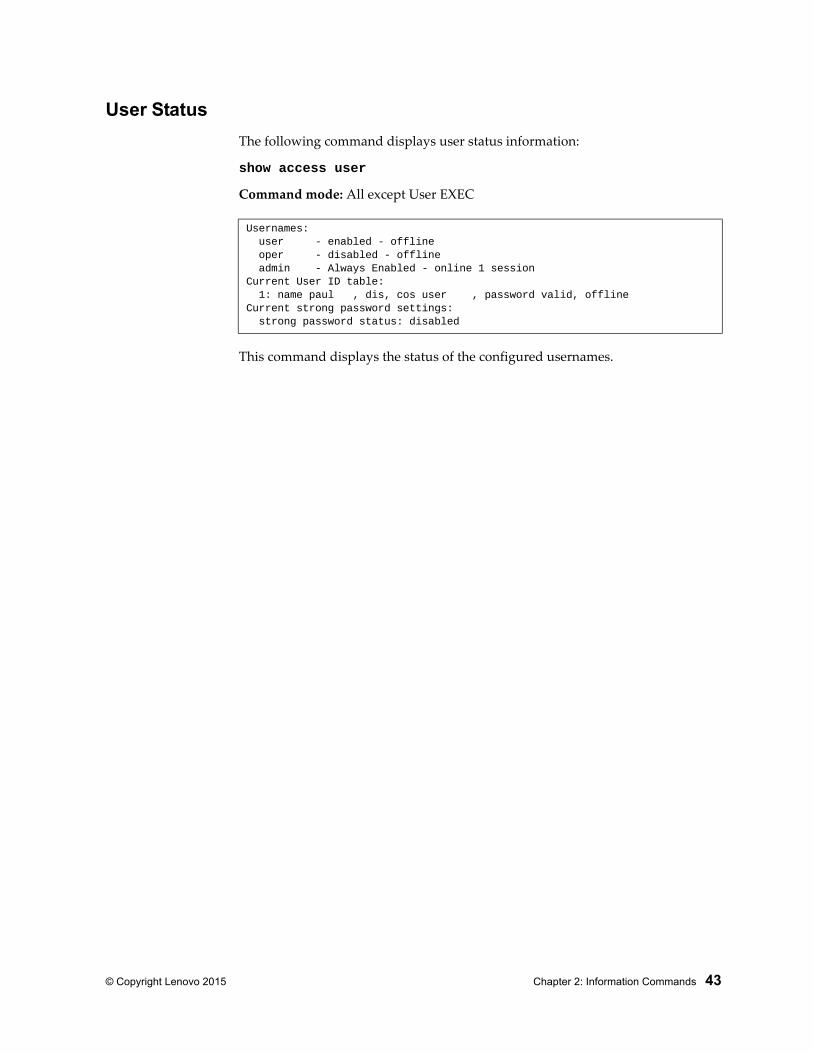
User Status
The following command displays user status information:
show access user
Command mode: All except User EXEC
This command displays the status of the configured usernames.
Usernames: user - enabled - offline oper - disabled - offline admin - Always Enabled - online 1 sessionCurrent User ID table: 1: name paul , dis, cos user , password valid, offlineCurrent strong password settings: strong password status: disabled
44 G7028/G7052 Command Reference for N/OS 8.1
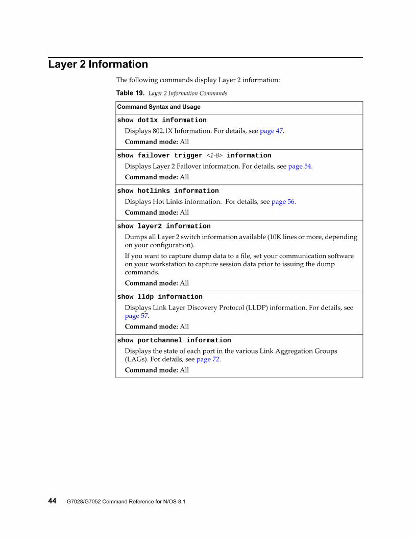
Layer 2 InformationThe following commands display Layer 2 information:
Table 19. Layer 2 Information Commands
Command Syntax and Usage
show dot1x information
Displays 802.1X Information. For details, see page 47.Command mode: All
show failover trigger <1-8> informationDisplays Layer 2 Failover information. For details, see page 54.Command mode: All
show hotlinks information
Displays Hot Links information. For details, see page 56. Command mode: All
show layer2 information
Dumps all Layer 2 switch information available (10K lines or more, depending on your configuration).If you want to capture dump data to a file, set your communication software on your workstation to capture session data prior to issuing the dump commands.Command mode: All
show lldp information
Displays Link Layer Discovery Protocol (LLDP) information. For details, see page 57.Command mode: All
show portchannel information
Displays the state of each port in the various Link Aggregation Groups (LAGs). For details, see page 72.Command mode: All
© Copyright Lenovo 2015 Chapter 2: Information Commands 45
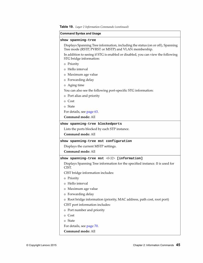
show spanning-tree
Displays Spanning Tree information, including the status (on or off), Spanning Tree mode (RSTP, PVRST or MSTP) and VLAN membership.In addition to seeing if STG is enabled or disabled, you can view the following STG bridge information: Priority Hello interval Maximum age value Forwarding delay Aging timeYou can also see the following port-specific STG information: Port alias and priority Cost StateFor details, see page 63.Command mode: All
show spanning-tree blockedports
Lists the ports blocked by each STP instance.Command mode: All
show spanning-tree mst configuration
Displays the current MSTP settings.Command mode: All
show spanning-tree mst <0-32> [information]Displays Spanning Tree information for the specified instance. 0 is used for CIST.CIST bridge information includes: Priority Hello interval Maximum age value Forwarding delay Root bridge information (priority, MAC address, path cost, root port)CIST port information includes: Port number and priority Cost StateFor details, see page 70.Command mode: All
Table 19. Layer 2 Information Commands (continued)
Command Syntax and Usage
46 G7028/G7052 Command Reference for N/OS 8.1
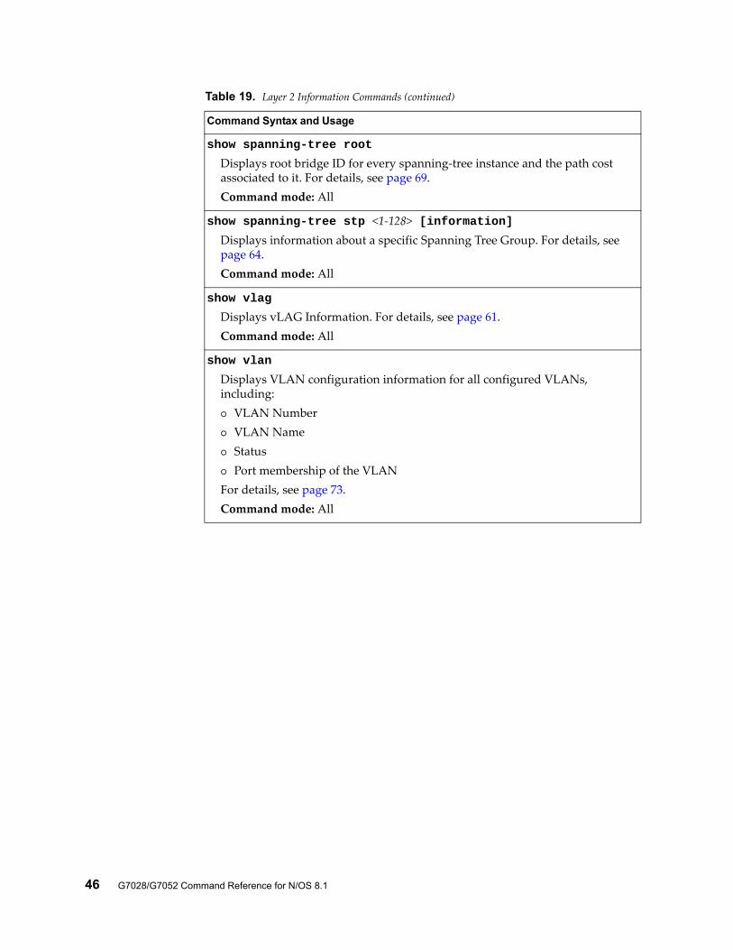
show spanning-tree root
Displays root bridge ID for every spanning-tree instance and the path cost associated to it. For details, see page 69.Command mode: All
show spanning-tree stp <1-128> [information]Displays information about a specific Spanning Tree Group. For details, see page 64.Command mode: All
show vlag
Displays vLAG Information. For details, see page 61.Command mode: All
show vlan
Displays VLAN configuration information for all configured VLANs, including: VLAN Number VLAN Name Status Port membership of the VLANFor details, see page 73.Command mode: All
Table 19. Layer 2 Information Commands (continued)
Command Syntax and Usage
© Copyright Lenovo 2015 Chapter 2: Information Commands 47
802.1X Information
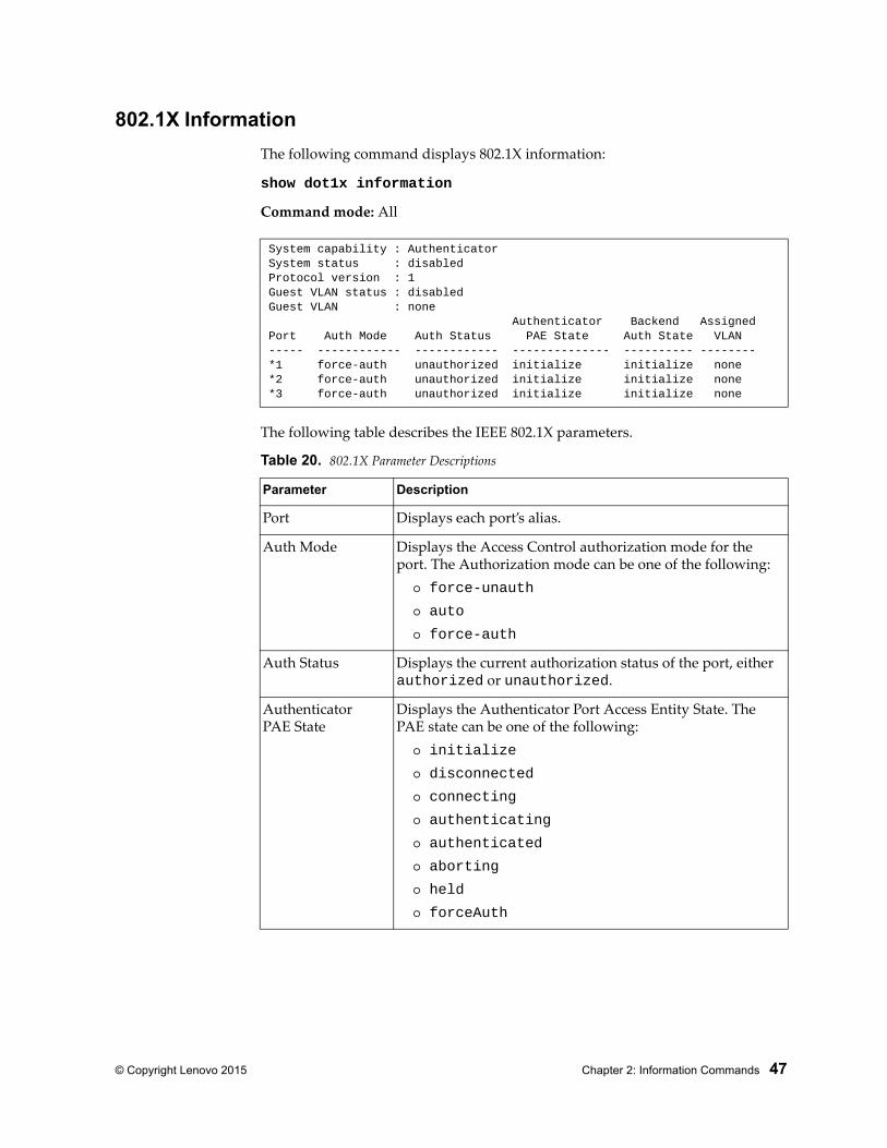
The following command displays 802.1X information:
show dot1x information
Command mode: All
The following table describes the IEEE 802.1X parameters.
System capability : AuthenticatorSystem status : disabledProtocol version : 1Guest VLAN status : disabledGuest VLAN : none Authenticator Backend AssignedPort Auth Mode Auth Status PAE State Auth State VLAN----- ------------ ------------ -------------- ---------- --------*1 force-auth unauthorized initialize initialize none*2 force-auth unauthorized initialize initialize none*3 force-auth unauthorized initialize initialize none
Table 20. 802.1X Parameter Descriptions
Parameter Description
Port Displays each port’s alias.
Auth Mode Displays the Access Control authorization mode for the port. The Authorization mode can be one of the following:
force-unauth
auto
force-auth
Auth Status Displays the current authorization status of the port, either authorized or unauthorized.
AuthenticatorPAE State
Displays the Authenticator Port Access Entity State. The PAE state can be one of the following:
initialize
disconnected
connecting
authenticating
authenticated
aborting
held
forceAuth
48 G7028/G7052 Command Reference for N/OS 8.1
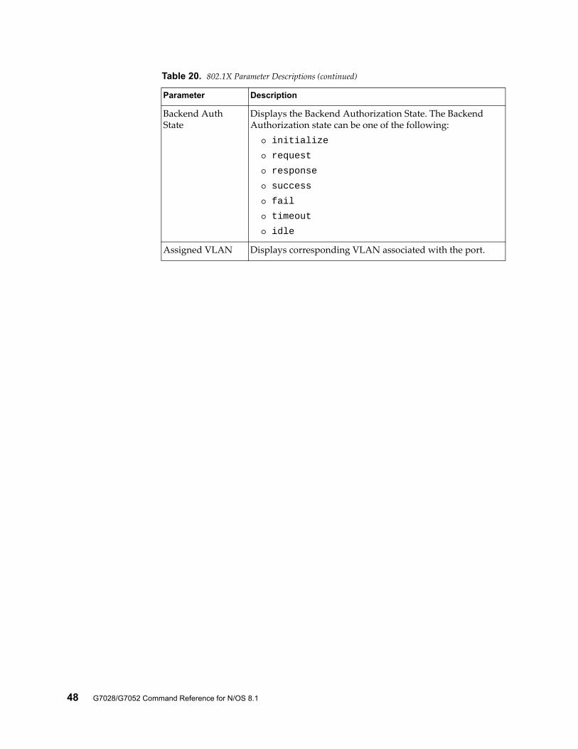
Backend Auth State
Displays the Backend Authorization State. The Backend Authorization state can be one of the following:
initialize
request
response
success
fail
timeout
idle
Assigned VLAN Displays corresponding VLAN associated with the port.
Table 20. 802.1X Parameter Descriptions (continued)
Parameter Description
© Copyright Lenovo 2015 Chapter 2: Information Commands 49
FDB Information
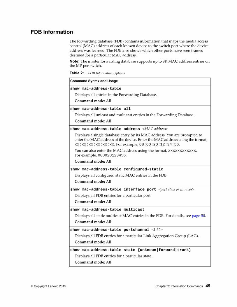
The forwarding database (FDB) contains information that maps the media access control (MAC) address of each known device to the switch port where the device address was learned. The FDB also shows which other ports have seen frames destined for a particular MAC address.Note: The master forwarding database supports up to 8K MAC address entries on the MP per switch.
Table 21. FDB Information Options
Command Syntax and Usage
show mac-address-table
Displays all entries in the Forwarding Database.Command mode: All
show mac-address-table all
Displays all unicast and multicast entries in the Forwarding Database.Command mode: All
show mac-address-table address <MAC address>Displays a single database entry by its MAC address. You are prompted to enter the MAC address of the device. Enter the MAC address using the format, xx:xx:xx:xx:xx:xx. For example, 08:00:20:12:34:56.You can also enter the MAC address using the format, xxxxxxxxxxxx.For example, 080020123456.Command mode: All
show mac-address-table configured-static
Displays all configured static MAC entries in the FDB.Command mode: All
show mac-address-table interface port <port alias or number>Displays all FDB entries for a particular port.Command mode: All
show mac-address-table multicast
Displays all static multicast MAC entries in the FDB. For details, see page 50.Command mode: All
show mac-address-table portchannel <1-32>Displays all FDB entries for a particular Link Aggregation Group (LAG).Command mode: All
show mac-address-table state {unknown|forward|trunk}
Displays all FDB entries for a particular state.Command mode: All
50 G7028/G7052 Command Reference for N/OS 8.1
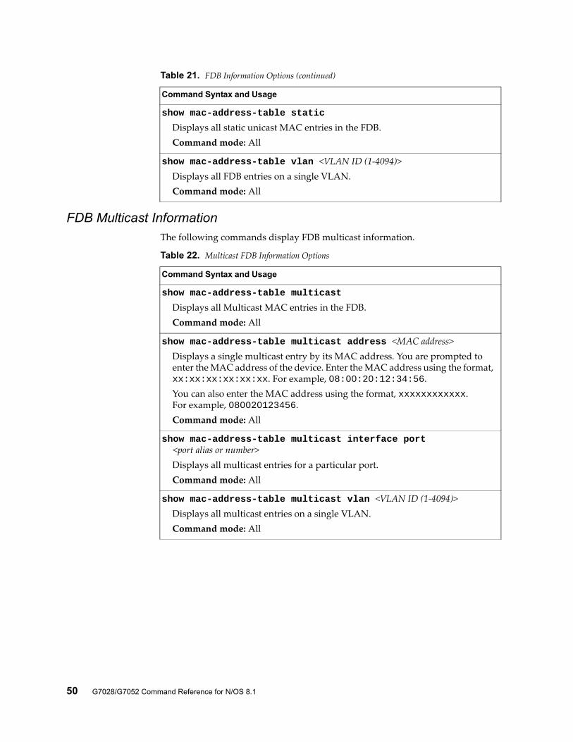
FDB Multicast InformationThe following commands display FDB multicast information.
show mac-address-table static
Displays all static unicast MAC entries in the FDB.Command mode: All
show mac-address-table vlan <VLAN ID (1-4094)>Displays all FDB entries on a single VLAN.Command mode: All
Table 21. FDB Information Options (continued)
Command Syntax and Usage
Table 22. Multicast FDB Information Options
Command Syntax and Usage
show mac-address-table multicast
Displays all Multicast MAC entries in the FDB.Command mode: All
show mac-address-table multicast address <MAC address>Displays a single multicast entry by its MAC address. You are prompted to enter the MAC address of the device. Enter the MAC address using the format, xx:xx:xx:xx:xx:xx. For example, 08:00:20:12:34:56.You can also enter the MAC address using the format, xxxxxxxxxxxx.For example, 080020123456.Command mode: All
show mac-address-table multicast interface port <port alias or number>
Displays all multicast entries for a particular port.Command mode: All
show mac-address-table multicast vlan <VLAN ID (1-4094)>Displays all multicast entries on a single VLAN.Command mode: All
© Copyright Lenovo 2015 Chapter 2: Information Commands 51
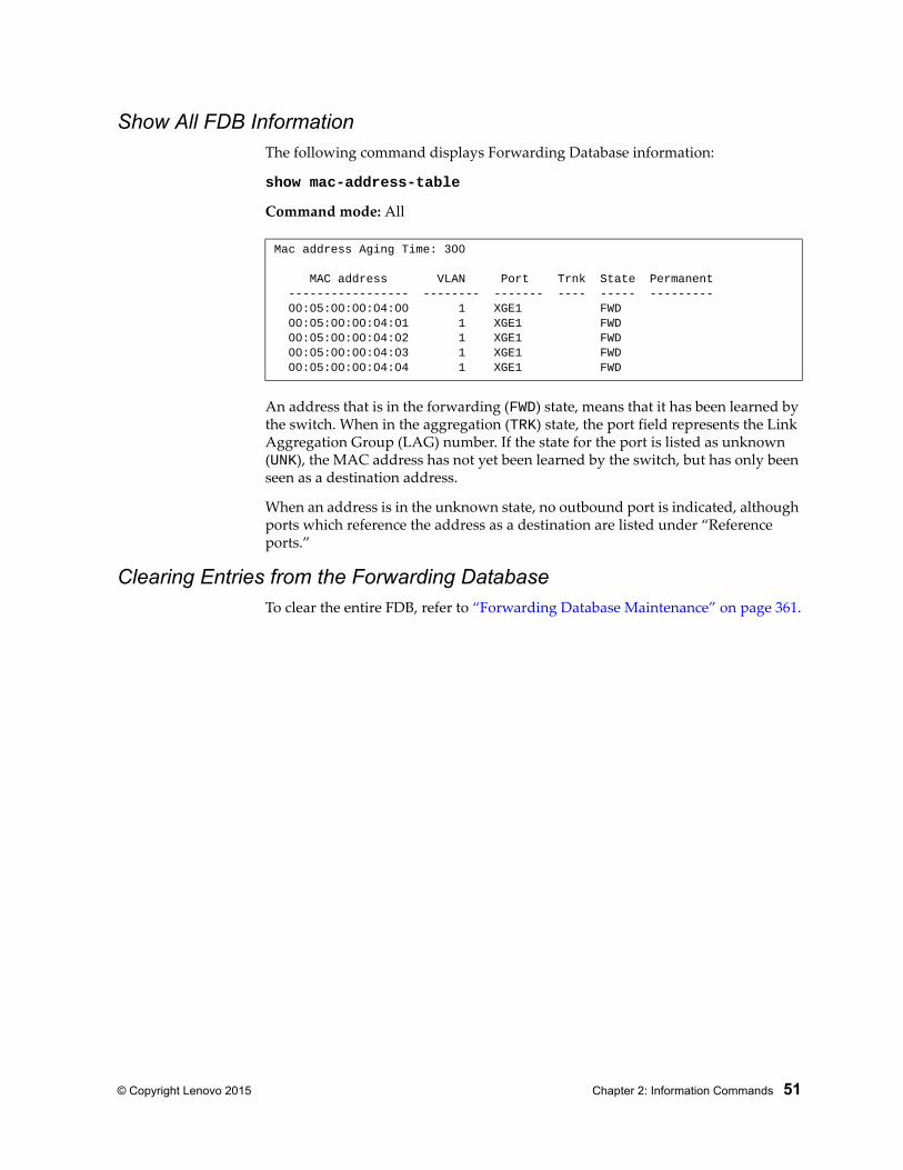
Show All FDB InformationThe following command displays Forwarding Database information:
show mac-address-table
Command mode: All
An address that is in the forwarding (FWD) state, means that it has been learned by the switch. When in the aggregation (TRK) state, the port field represents the Link Aggregation Group (LAG) number. If the state for the port is listed as unknown (UNK), the MAC address has not yet been learned by the switch, but has only been seen as a destination address.
When an address is in the unknown state, no outbound port is indicated, although ports which reference the address as a destination are listed under “Reference ports.”
Clearing Entries from the Forwarding DatabaseTo clear the entire FDB, refer to “Forwarding Database Maintenance” on page 361.
Mac address Aging Time: 300
MAC address VLAN Port Trnk State Permanent ----------------- -------- ------- ---- ----- --------- 00:05:00:00:04:00 1 XGE1 FWD 00:05:00:00:04:01 1 XGE1 FWD 00:05:00:00:04:02 1 XGE1 FWD 00:05:00:00:04:03 1 XGE1 FWD 00:05:00:00:04:04 1 XGE1 FWD
52 G7028/G7052 Command Reference for N/OS 8.1
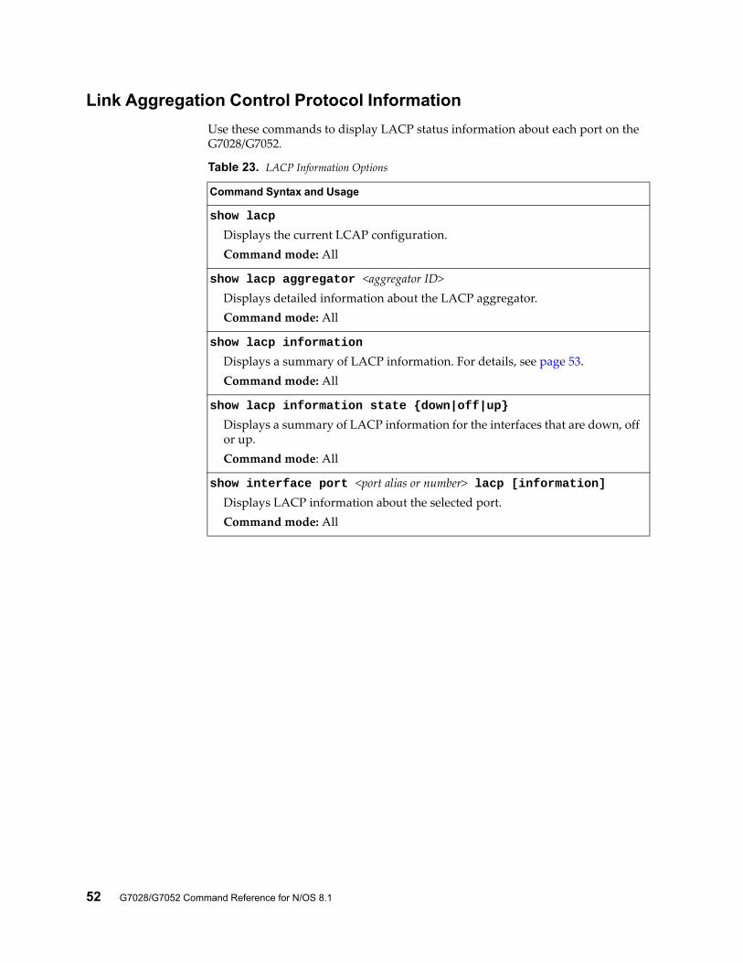
Link Aggregation Control Protocol Information
Use these commands to display LACP status information about each port on the G7028/G7052.
Table 23. LACP Information Options
Command Syntax and Usage
show lacp
Displays the current LCAP configuration.Command mode: All
show lacp aggregator <aggregator ID>Displays detailed information about the LACP aggregator.Command mode: All
show lacp information
Displays a summary of LACP information. For details, see page 53.Command mode: All
show lacp information state {down|off|up}
Displays a summary of LACP information for the interfaces that are down, off or up.Command mode: All
show interface port <port alias or number> lacp [information]Displays LACP information about the selected port.Command mode: All
© Copyright Lenovo 2015 Chapter 2: Information Commands 53
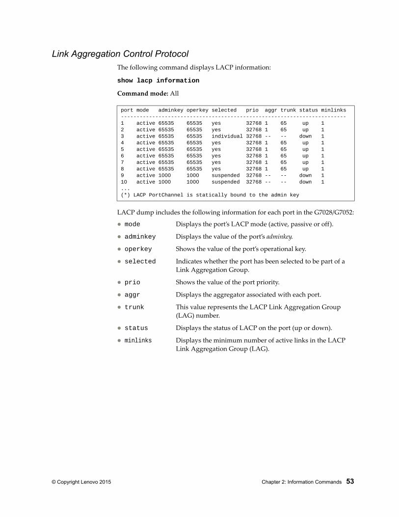
Link Aggregation Control ProtocolThe following command displays LACP information:
show lacp information
Command mode: All
LACP dump includes the following information for each port in the G7028/G7052:
mode Displays the port’s LACP mode (active, passive or off).
adminkey Displays the value of the port’s adminkey.
operkey Shows the value of the port’s operational key.
selected Indicates whether the port has been selected to be part of a Link Aggregation Group.
prio Shows the value of the port priority.
aggr Displays the aggregator associated with each port.
trunk This value represents the LACP Link Aggregation Group (LAG) number.
status Displays the status of LACP on the port (up or down).
minlinks Displays the minimum number of active links in the LACP Link Aggregation Group (LAG).
port mode adminkey operkey selected prio aggr trunk status minlinks------------------------------------------------------------------------1 active 65535 65535 yes 32768 1 65 up 12 active 65535 65535 yes 32768 1 65 up 13 active 65535 65535 individual 32768 -- -- down 14 active 65535 65535 yes 32768 1 65 up 15 active 65535 65535 yes 32768 1 65 up 16 active 65535 65535 yes 32768 1 65 up 17 active 65535 65535 yes 32768 1 65 up 18 active 65535 65535 yes 32768 1 65 up 19 active 1000 1000 suspended 32768 -- -- down 110 active 1000 1000 suspended 32768 -- -- down 1...(*) LACP PortChannel is statically bound to the admin key
54 G7028/G7052 Command Reference for N/OS 8.1
Layer 2 Failover Information
The following commands display Layer 2 Failover information:
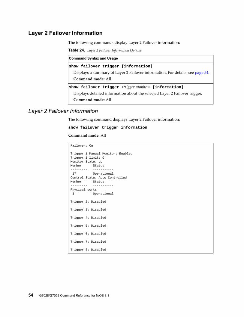
Layer 2 Failover InformationThe following command displays Layer 2 Failover information:
show failover trigger information
Command mode: All
Table 24. Layer 2 Failover Information Options
Command Syntax and Usage
show failover trigger [information]
Displays a summary of Layer 2 Failover information. For details, see page 54.Command mode: All
show failover trigger <trigger number> [information]Displays detailed information about the selected Layer 2 Failover trigger.Command mode: All
Failover: On
Trigger 1 Manual Monitor: EnabledTrigger 1 limit: 0Monitor State: UpMember Status--------- ----------- 17 OperationalControl State: Auto ControlledMember Status--------- -----------Physical ports 1 Operational
Trigger 2: Disabled
Trigger 3: Disabled
Trigger 4: Disabled
Trigger 5: Disabled
Trigger 6: Disabled
Trigger 7: Disabled
Trigger 8: Disabled
© Copyright Lenovo 2015 Chapter 2: Information Commands 55
A monitor port’s Failover status is Operational only if all the following conditions hold true:
Port link is up.
If Spanning-Tree is enabled, the port is in the Forwarding state.
If the port is a member of an LACP Link Aggregation Group (LAG), the port is aggregated.
If any of these conditions are not true, the monitor port is considered to be failed.
A control port is considered to be operational if the monitor trigger state is Up. Even if a port’s link status is Down, Spanning-Tree status is Blocking, and the LACP status is Not Aggregated, from a teaming perspective the port status is Operational, since the trigger is Up.
A control port’s status is displayed as Failed only if the monitor trigger state is Down.
56 G7028/G7052 Command Reference for N/OS 8.1
Hot Links Information
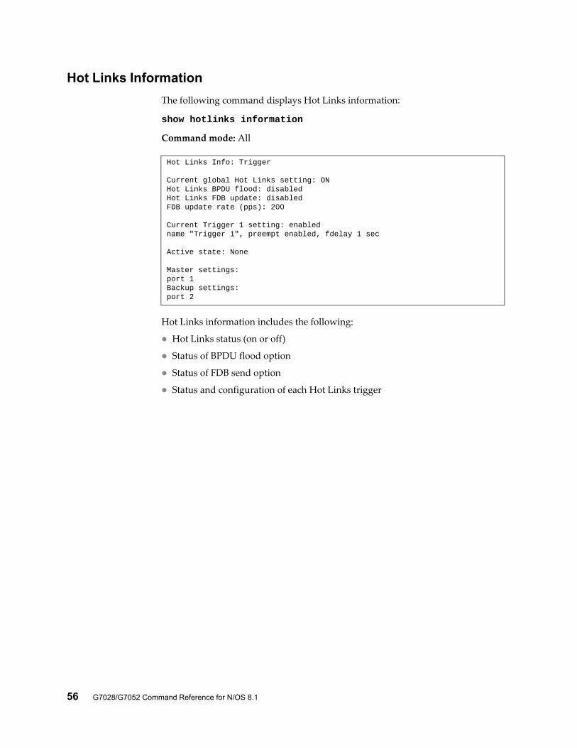
The following command displays Hot Links information:
show hotlinks information
Command mode: All
Hot Links information includes the following:
Hot Links status (on or off)
Status of BPDU flood option
Status of FDB send option
Status and configuration of each Hot Links trigger
Hot Links Info: Trigger
Current global Hot Links setting: ONHot Links BPDU flood: disabledHot Links FDB update: disabledFDB update rate (pps): 200
Current Trigger 1 setting: enabledname "Trigger 1", preempt enabled, fdelay 1 sec
Active state: None
Master settings:port 1Backup settings:port 2
© Copyright Lenovo 2015 Chapter 2: Information Commands 57
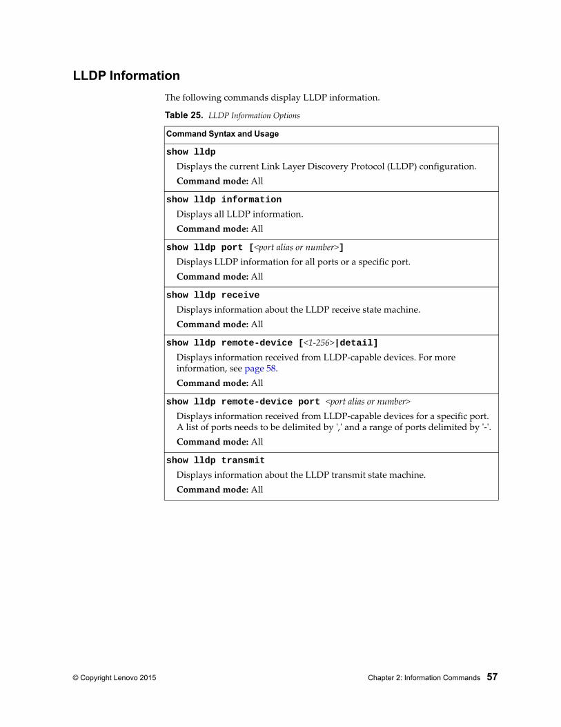
LLDP Information
The following commands display LLDP information.
Table 25. LLDP Information Options
Command Syntax and Usage
show lldp
Displays the current Link Layer Discovery Protocol (LLDP) configuration.Command mode: All
show lldp information
Displays all LLDP information.Command mode: All
show lldp port [<port alias or number>]Displays LLDP information for all ports or a specific port.Command mode: All
show lldp receive
Displays information about the LLDP receive state machine.Command mode: All
show lldp remote-device [<1-256>|detail]Displays information received from LLDP-capable devices. For more information, see page 58.Command mode: All
show lldp remote-device port <port alias or number>Displays information received from LLDP-capable devices for a specific port. A list of ports needs to be delimited by ',' and a range of ports delimited by '-'.Command mode: All
show lldp transmit
Displays information about the LLDP transmit state machine.Command mode: All
58 G7028/G7052 Command Reference for N/OS 8.1
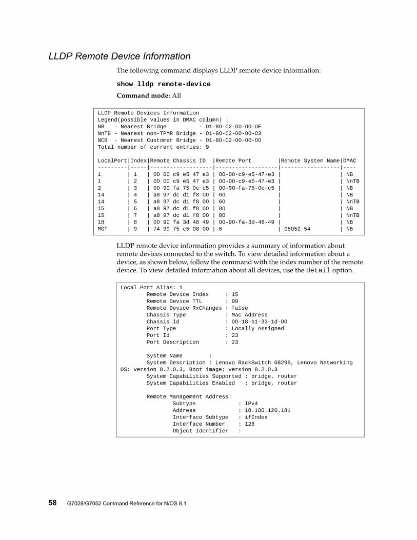
LLDP Remote Device InformationThe following command displays LLDP remote device information:
show lldp remote-device
Command mode: All
LLDP remote device information provides a summary of information about remote devices connected to the switch. To view detailed information about a device, as shown below, follow the command with the index number of the remote device. To view detailed information about all devices, use the detail option.
LLDP Remote Devices InformationLegend(possible values in DMAC column) :NB - Nearest Bridge - 01-80-C2-00-00-0ENnTB - Nearest non-TPMR Bridge - 01-80-C2-00-00-03NCB - Nearest Customer Bridge - 01-80-C2-00-00-00Total number of current entries: 9
LocalPort|Index|Remote Chassis ID |Remote Port |Remote System Name|DMAC---------|-----|-------------------|-------------------|------------------|----1 | 1 | 00 00 c9 e5 47 e3 | 00-00-c9-e5-47-e3 | | NB 1 | 2 | 00 00 c9 e5 47 e3 | 00-00-c9-e5-47-e3 | | NnTB2 | 3 | 00 90 fa 75 0e c5 | 00-90-fa-75-0e-c5 | | NB14 | 4 | a8 97 dc d1 f8 00 | 60 | | NB14 | 5 | a8 97 dc d1 f8 00 | 60 | | NnTB15 | 6 | a8 97 dc d1 f8 00 | 80 | | NB15 | 7 | a8 97 dc d1 f8 00 | 80 | | NnTB18 | 8 | 00 90 fa 3d 48 49 | 00-90-fa-3d-48-49 | | NBMGT | 9 | 74 99 75 c5 08 00 | 6 | G8052-54 | NB
Local Port Alias: 1 Remote Device Index : 15 Remote Device TTL : 99 Remote Device RxChanges : false Chassis Type : Mac Address Chassis Id : 00-18-b1-33-1d-00 Port Type : Locally Assigned Port Id : 23 Port Description : 23
System Name : System Description : Lenovo RackSwitch G8296, Lenovo Networking OS: version 8.2.0.3, Boot image: version 8.2.0.3 System Capabilities Supported : bridge, router System Capabilities Enabled : bridge, router
Remote Management Address: Subtype : IPv4 Address : 10.100.120.181 Interface Subtype : ifIndex Interface Number : 128 Object Identifier :
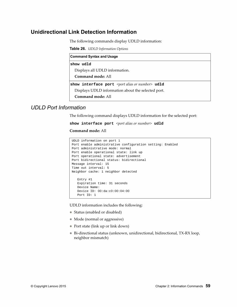
© Copyright Lenovo 2015 Chapter 2: Information Commands 59
Unidirectional Link Detection Information
The following commands display UDLD information:
UDLD Port InformationThe following command displays UDLD information for the selected port:
show interface port <port alias or number> udld
Command mode: All
UDLD information includes the following:
Status (enabled or disabled)
Mode (normal or aggressive)
Port state (link up or link down)
Bi-directional status (unknown, unidirectional, bidirectional, TX-RX loop, neighbor mismatch)
Table 26. UDLD Information Options
Command Syntax and Usage
show udld
Displays all UDLD information.Command mode: All
show interface port <port alias or number> udldDisplays UDLD information about the selected port.Command mode: All
UDLD information on port 1Port enable administrative configuration setting: EnabledPort administrative mode: normalPort enable operational state: link upPort operational state: advertisementPort bidirectional status: bidirectionalMessage interval: 15Time out interval: 5Neighbor cache: 1 neighbor detected
Entry #1 Expiration time: 31 seconds Device Name: Device ID: 00:da:c0:00:04:00 Port ID: 1
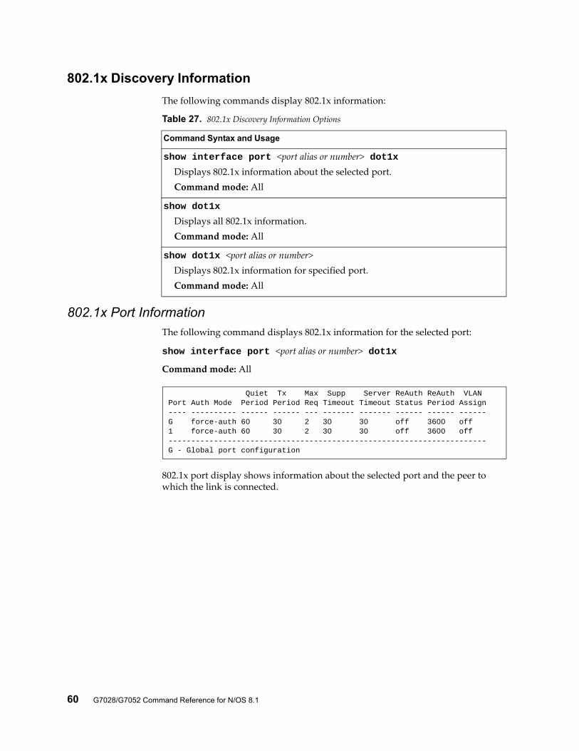
60 G7028/G7052 Command Reference for N/OS 8.1
802.1x Discovery Information
The following commands display 802.1x information:
802.1x Port InformationThe following command displays 802.1x information for the selected port:
show interface port <port alias or number> dot1x
Command mode: All
802.1x port display shows information about the selected port and the peer to which the link is connected.
Table 27. 802.1x Discovery Information Options
Command Syntax and Usage
show interface port <port alias or number> dot1xDisplays 802.1x information about the selected port.Command mode: All
show dot1x
Displays all 802.1x information.Command mode: All
show dot1x <port alias or number>Displays 802.1x information for specified port.Command mode: All
Quiet Tx Max Supp Server ReAuth ReAuth VLANPort Auth Mode Period Period Req Timeout Timeout Status Period Assign---- ---------- ------ ------ --- ------- ------- ------ ------ ------G force-auth 60 30 2 30 30 off 3600 off1 force-auth 60 30 2 30 30 off 3600 off----------------------------------------------------------------------G - Global port configuration
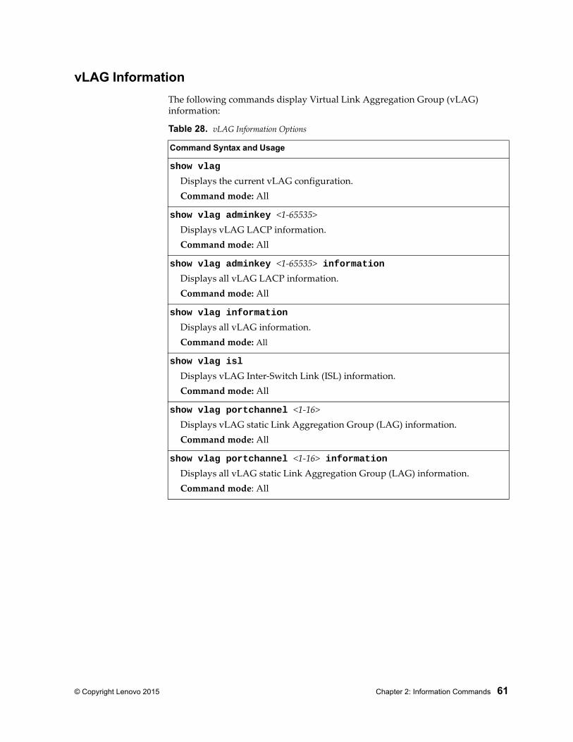
© Copyright Lenovo 2015 Chapter 2: Information Commands 61
vLAG Information
The following commands display Virtual Link Aggregation Group (vLAG) information:
Table 28. vLAG Information Options
Command Syntax and Usage
show vlag
Displays the current vLAG configuration.Command mode: All
show vlag adminkey <1-65535>Displays vLAG LACP information.Command mode: All
show vlag adminkey <1-65535> informationDisplays all vLAG LACP information.Command mode: All
show vlag information
Displays all vLAG information.Command mode: All
show vlag isl
Displays vLAG Inter-Switch Link (ISL) information.Command mode: All
show vlag portchannel <1-16>Displays vLAG static Link Aggregation Group (LAG) information.Command mode: All
show vlag portchannel <1-16> informationDisplays all vLAG static Link Aggregation Group (LAG) information.Command mode: All
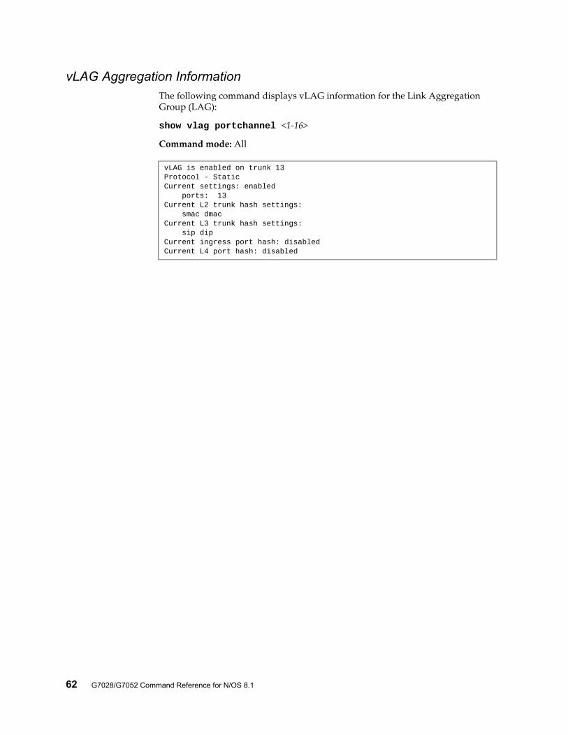
62 G7028/G7052 Command Reference for N/OS 8.1
vLAG Aggregation InformationThe following command displays vLAG information for the Link Aggregation Group (LAG):
show vlag portchannel <1-16>
Command mode: All
vLAG is enabled on trunk 13Protocol - StaticCurrent settings: enabled ports: 13Current L2 trunk hash settings: smac dmacCurrent L3 trunk hash settings: sip dipCurrent ingress port hash: disabledCurrent L4 port hash: disabled
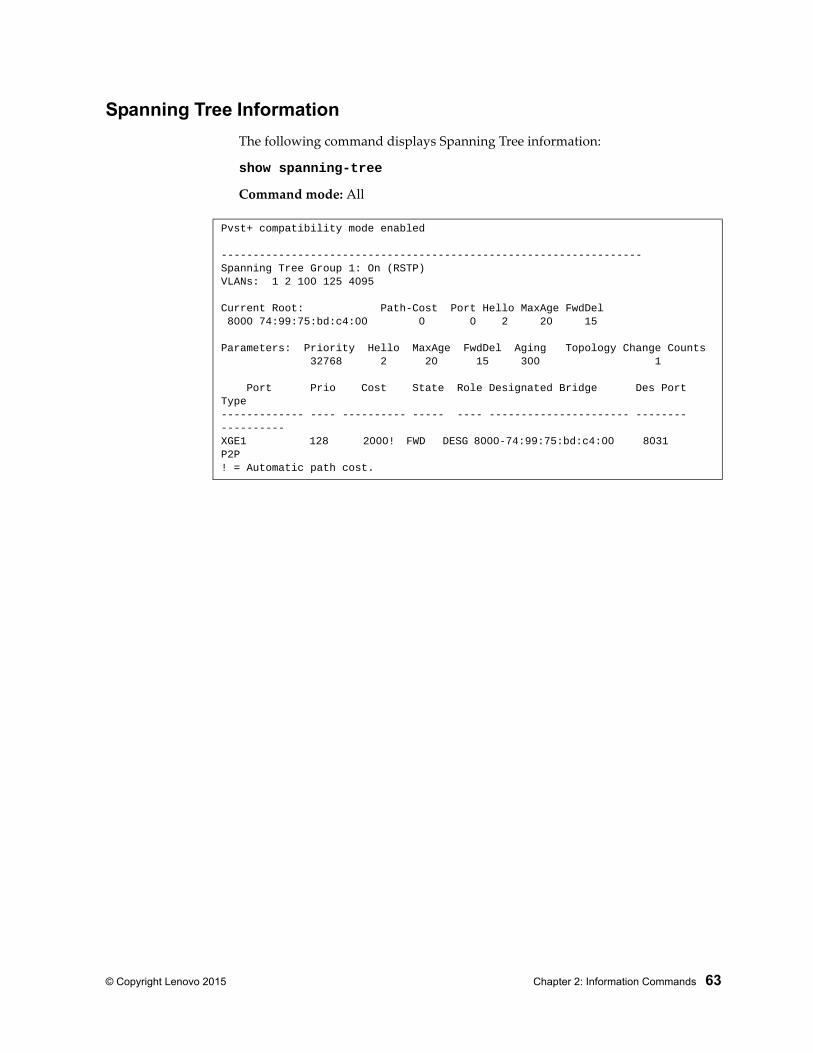
© Copyright Lenovo 2015 Chapter 2: Information Commands 63
Spanning Tree Information
The following command displays Spanning Tree information:
show spanning-tree
Command mode: All
Pvst+ compatibility mode enabled
------------------------------------------------------------------Spanning Tree Group 1: On (RSTP)VLANs: 1 2 100 125 4095
Current Root: Path-Cost Port Hello MaxAge FwdDel 8000 74:99:75:bd:c4:00 0 0 2 20 15
Parameters: Priority Hello MaxAge FwdDel Aging Topology Change Counts 32768 2 20 15 300 1
Port Prio Cost State Role Designated Bridge Des Port Type------------- ---- ---------- ----- ---- ---------------------- -------- ----------XGE1 128 2000! FWD DESG 8000-74:99:75:bd:c4:00 8031 P2P! = Automatic path cost.
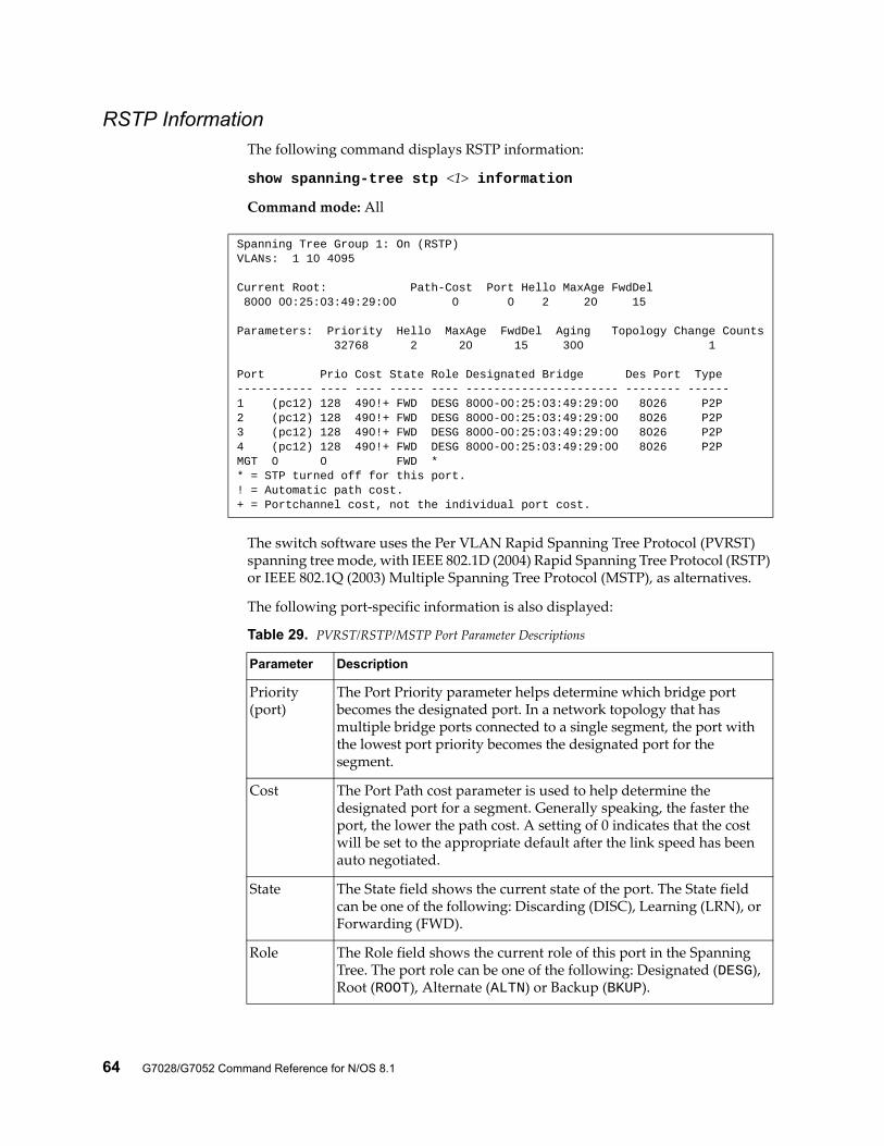
64 G7028/G7052 Command Reference for N/OS 8.1
RSTP InformationThe following command displays RSTP information:
show spanning-tree stp <1> information
Command mode: All
The switch software uses the Per VLAN Rapid Spanning Tree Protocol (PVRST) spanning tree mode, with IEEE 802.1D (2004) Rapid Spanning Tree Protocol (RSTP) or IEEE 802.1Q (2003) Multiple Spanning Tree Protocol (MSTP), as alternatives.
The following port-specific information is also displayed:
Spanning Tree Group 1: On (RSTP)VLANs: 1 10 4095
Current Root: Path-Cost Port Hello MaxAge FwdDel 8000 00:25:03:49:29:00 0 0 2 20 15
Parameters: Priority Hello MaxAge FwdDel Aging Topology Change Counts 32768 2 20 15 300 1
Port Prio Cost State Role Designated Bridge Des Port Type----------- ---- ---- ----- ---- ---------------------- -------- ------1 (pc12) 128 490!+ FWD DESG 8000-00:25:03:49:29:00 8026 P2P2 (pc12) 128 490!+ FWD DESG 8000-00:25:03:49:29:00 8026 P2P3 (pc12) 128 490!+ FWD DESG 8000-00:25:03:49:29:00 8026 P2P4 (pc12) 128 490!+ FWD DESG 8000-00:25:03:49:29:00 8026 P2PMGT 0 0 FWD ** = STP turned off for this port.! = Automatic path cost.+ = Portchannel cost, not the individual port cost.
Table 29. PVRST/RSTP/MSTP Port Parameter Descriptions
Parameter Description
Priority (port)
The Port Priority parameter helps determine which bridge port becomes the designated port. In a network topology that has multiple bridge ports connected to a single segment, the port with the lowest port priority becomes the designated port for the segment.
Cost The Port Path cost parameter is used to help determine the designated port for a segment. Generally speaking, the faster the port, the lower the path cost. A setting of 0 indicates that the cost will be set to the appropriate default after the link speed has been auto negotiated.
State The State field shows the current state of the port. The State field can be one of the following: Discarding (DISC), Learning (LRN), or Forwarding (FWD).
Role The Role field shows the current role of this port in the Spanning Tree. The port role can be one of the following: Designated (DESG), Root (ROOT), Alternate (ALTN) or Backup (BKUP).
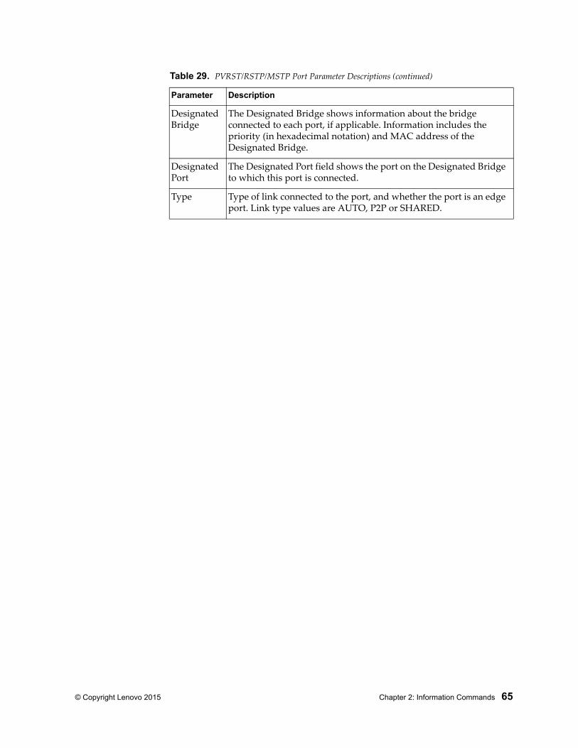
© Copyright Lenovo 2015 Chapter 2: Information Commands 65
Designated Bridge
The Designated Bridge shows information about the bridge connected to each port, if applicable. Information includes the priority (in hexadecimal notation) and MAC address of the Designated Bridge.
Designated Port
The Designated Port field shows the port on the Designated Bridge to which this port is connected.
Type Type of link connected to the port, and whether the port is an edge port. Link type values are AUTO, P2P or SHARED.
Table 29. PVRST/RSTP/MSTP Port Parameter Descriptions (continued)
Parameter Description
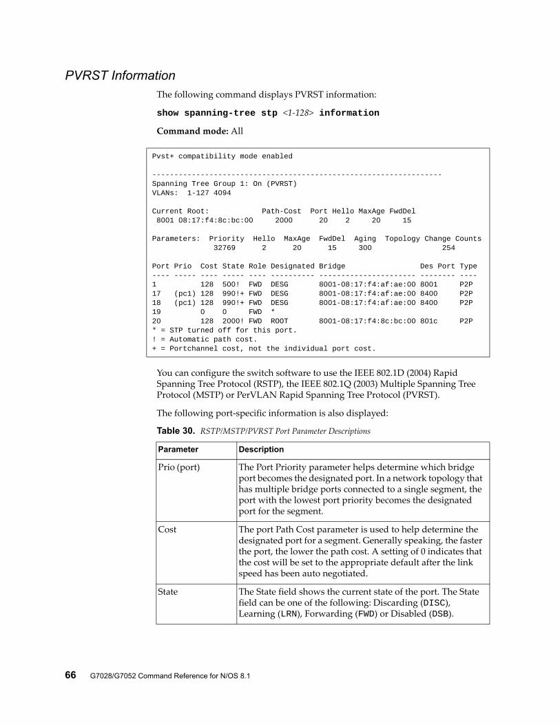
66 G7028/G7052 Command Reference for N/OS 8.1
PVRST InformationThe following command displays PVRST information:
show spanning-tree stp <1-128> information
Command mode: All
You can configure the switch software to use the IEEE 802.1D (2004) Rapid Spanning Tree Protocol (RSTP), the IEEE 802.1Q (2003) Multiple Spanning Tree Protocol (MSTP) or PerVLAN Rapid Spanning Tree Protocol (PVRST).
The following port-specific information is also displayed:
Pvst+ compatibility mode enabled
------------------------------------------------------------------Spanning Tree Group 1: On (PVRST)VLANs: 1-127 4094
Current Root: Path-Cost Port Hello MaxAge FwdDel 8001 08:17:f4:8c:bc:00 2000 20 2 20 15
Parameters: Priority Hello MaxAge FwdDel Aging Topology Change Counts 32769 2 20 15 300 254
Port Prio Cost State Role Designated Bridge Des Port Type---- ----- ---- ----- ---- ---------- ---------------------- -------- ----1 128 500! FWD DESG 8001-08:17:f4:af:ae:00 8001 P2P17 (pc1) 128 990!+ FWD DESG 8001-08:17:f4:af:ae:00 8400 P2P18 (pc1) 128 990!+ FWD DESG 8001-08:17:f4:af:ae:00 8400 P2P19 0 0 FWD *20 128 2000! FWD ROOT 8001-08:17:f4:8c:bc:00 801c P2P* = STP turned off for this port.! = Automatic path cost.+ = Portchannel cost, not the individual port cost.
Table 30. RSTP/MSTP/PVRST Port Parameter Descriptions
Parameter Description
Prio (port) The Port Priority parameter helps determine which bridge port becomes the designated port. In a network topology that has multiple bridge ports connected to a single segment, the port with the lowest port priority becomes the designated port for the segment.
Cost The port Path Cost parameter is used to help determine the designated port for a segment. Generally speaking, the faster the port, the lower the path cost. A setting of 0 indicates that the cost will be set to the appropriate default after the link speed has been auto negotiated.
State The State field shows the current state of the port. The State field can be one of the following: Discarding (DISC), Learning (LRN), Forwarding (FWD) or Disabled (DSB).
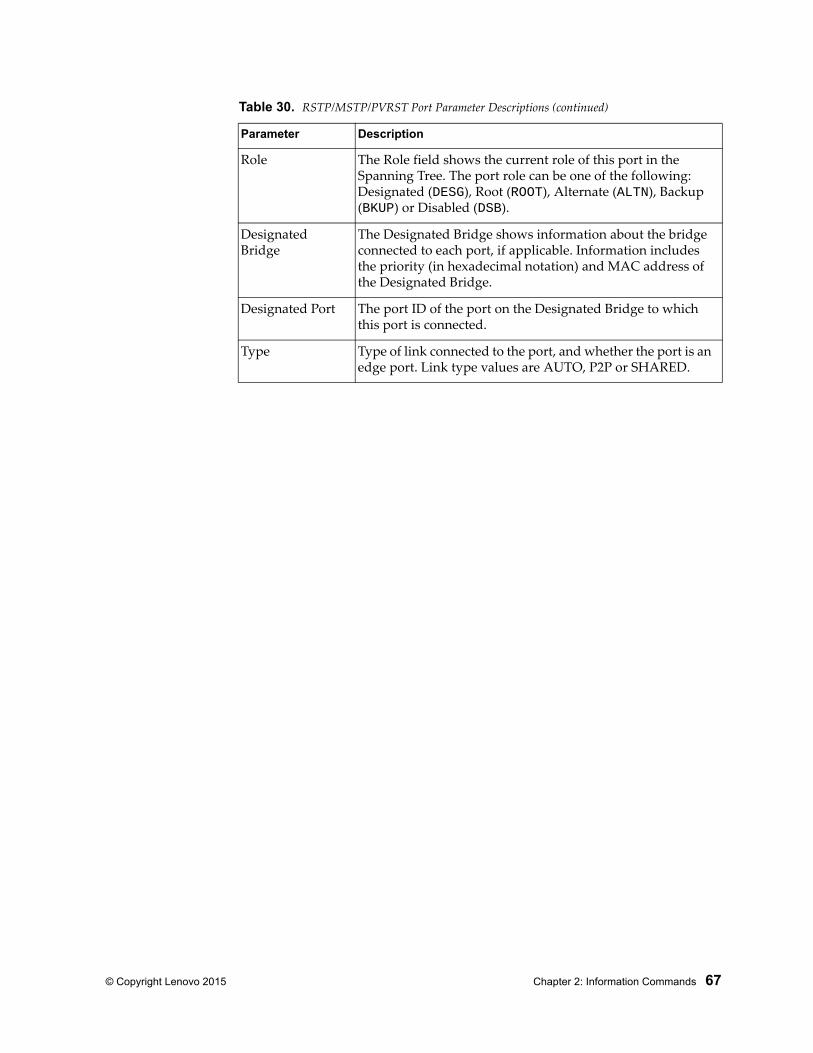
© Copyright Lenovo 2015 Chapter 2: Information Commands 67
Role The Role field shows the current role of this port in the Spanning Tree. The port role can be one of the following: Designated (DESG), Root (ROOT), Alternate (ALTN), Backup (BKUP) or Disabled (DSB).
Designated Bridge
The Designated Bridge shows information about the bridge connected to each port, if applicable. Information includes the priority (in hexadecimal notation) and MAC address of the Designated Bridge.
Designated Port The port ID of the port on the Designated Bridge to which this port is connected.
Type Type of link connected to the port, and whether the port is an edge port. Link type values are AUTO, P2P or SHARED.
Table 30. RSTP/MSTP/PVRST Port Parameter Descriptions (continued)
Parameter Description
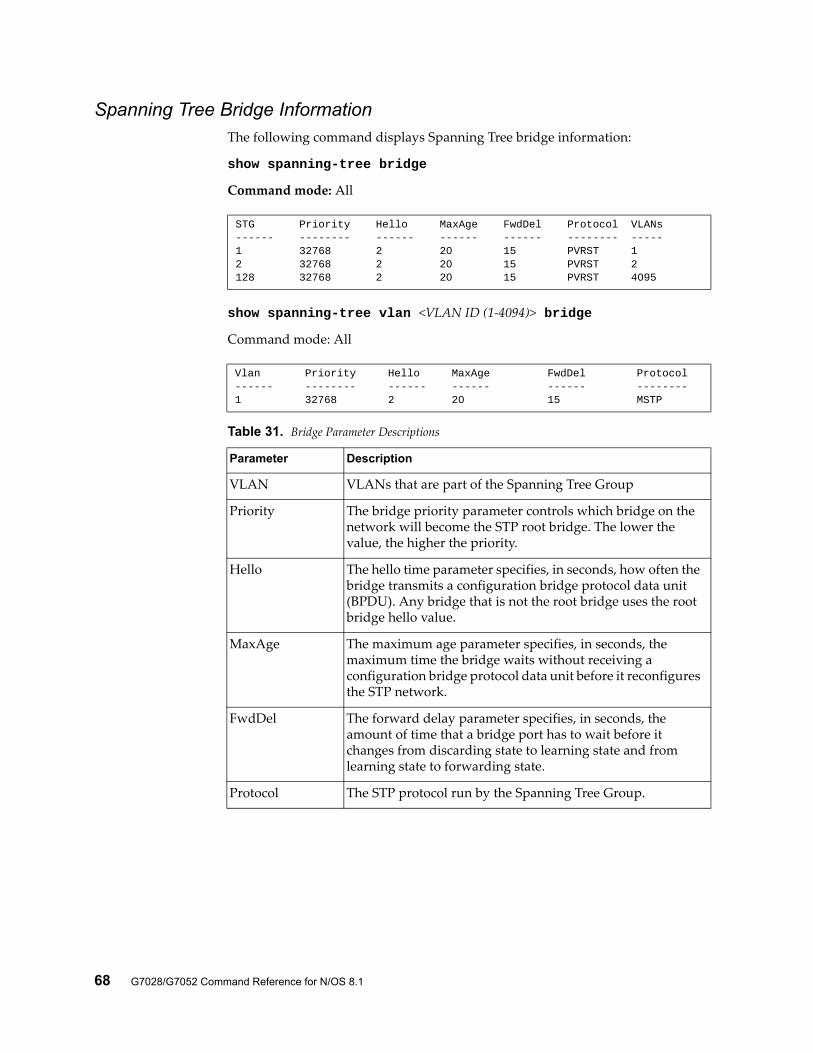
68 G7028/G7052 Command Reference for N/OS 8.1
Spanning Tree Bridge InformationThe following command displays Spanning Tree bridge information:
show spanning-tree bridge
Command mode: All
show spanning-tree vlan <VLAN ID (1-4094)> bridge
Command mode: All
STG Priority Hello MaxAge FwdDel Protocol VLANs------ -------- ------ ------ ------ -------- -----1 32768 2 20 15 PVRST 12 32768 2 20 15 PVRST 2128 32768 2 20 15 PVRST 4095
Vlan Priority Hello MaxAge FwdDel Protocol------ -------- ------ ------ ------ --------1 32768 2 20 15 MSTP
Table 31. Bridge Parameter Descriptions
Parameter Description
VLAN VLANs that are part of the Spanning Tree Group
Priority The bridge priority parameter controls which bridge on the network will become the STP root bridge. The lower the value, the higher the priority.
Hello The hello time parameter specifies, in seconds, how often the bridge transmits a configuration bridge protocol data unit (BPDU). Any bridge that is not the root bridge uses the root bridge hello value.
MaxAge The maximum age parameter specifies, in seconds, the maximum time the bridge waits without receiving a configuration bridge protocol data unit before it reconfigures the STP network.
FwdDel The forward delay parameter specifies, in seconds, the amount of time that a bridge port has to wait before it changes from discarding state to learning state and from learning state to forwarding state.
Protocol The STP protocol run by the Spanning Tree Group.
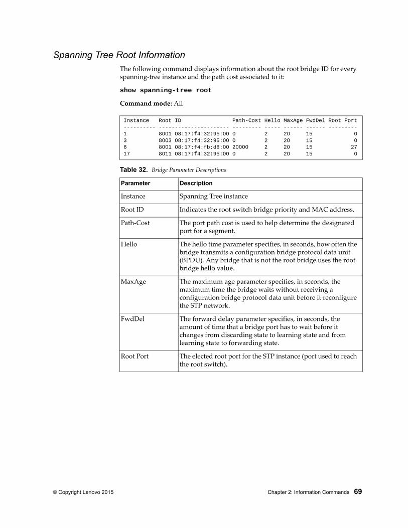
© Copyright Lenovo 2015 Chapter 2: Information Commands 69
Spanning Tree Root InformationThe following command displays information about the root bridge ID for every spanning-tree instance and the path cost associated to it:
show spanning-tree root
Command mode: All
Instance Root ID Path-Cost Hello MaxAge FwdDel Root Port---------- ---------------------- --------- ----- ------ ------ ---------1 8001 08:17:f4:32:95:00 0 2 20 15 03 8003 08:17:f4:32:95:00 0 2 20 15 06 8001 08:17:f4:fb:d8:00 20000 2 20 15 2717 8011 08:17:f4:32:95:00 0 2 20 15 0
Table 32. Bridge Parameter Descriptions
Parameter Description
Instance Spanning Tree instance
Root ID Indicates the root switch bridge priority and MAC address.
Path-Cost The port path cost is used to help determine the designated port for a segment.
Hello The hello time parameter specifies, in seconds, how often the bridge transmits a configuration bridge protocol data unit (BPDU). Any bridge that is not the root bridge uses the root bridge hello value.
MaxAge The maximum age parameter specifies, in seconds, the maximum time the bridge waits without receiving a configuration bridge protocol data unit before it reconfigure the STP network.
FwdDel The forward delay parameter specifies, in seconds, the amount of time that a bridge port has to wait before it changes from discarding state to learning state and from learning state to forwarding state.
Root Port The elected root port for the STP instance (port used to reach the root switch).
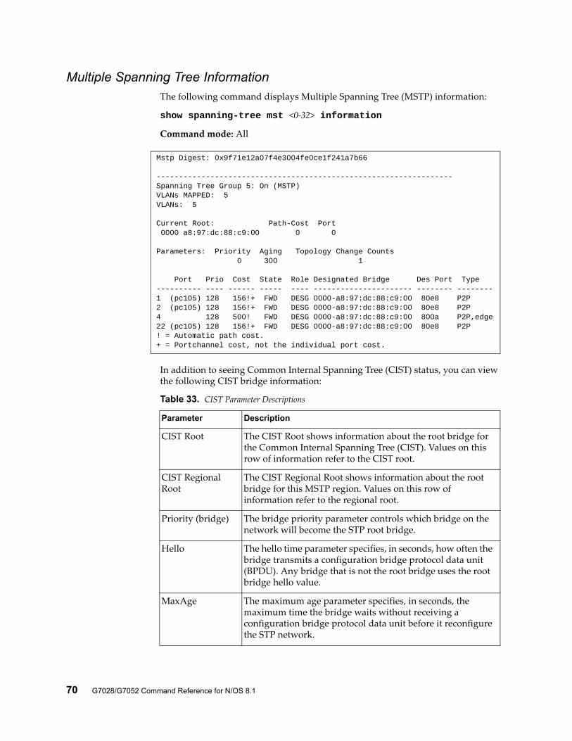
70 G7028/G7052 Command Reference for N/OS 8.1
Multiple Spanning Tree InformationThe following command displays Multiple Spanning Tree (MSTP) information:
show spanning-tree mst <0-32> information
Command mode: All
In addition to seeing Common Internal Spanning Tree (CIST) status, you can view the following CIST bridge information:
Mstp Digest: 0x9f71e12a07f4e3004fe0ce1f241a7b66
------------------------------------------------------------------Spanning Tree Group 5: On (MSTP)VLANs MAPPED: 5VLANs: 5
Current Root: Path-Cost Port 0000 a8:97:dc:88:c9:00 0 0
Parameters: Priority Aging Topology Change Counts 0 300 1
Port Prio Cost State Role Designated Bridge Des Port Type---------- ---- ------ ----- ---- ---------------------- -------- --------1 (pc105) 128 156!+ FWD DESG 0000-a8:97:dc:88:c9:00 80e8 P2P2 (pc105) 128 156!+ FWD DESG 0000-a8:97:dc:88:c9:00 80e8 P2P4 128 500! FWD DESG 0000-a8:97:dc:88:c9:00 800a P2P,edge22 (pc105) 128 156!+ FWD DESG 0000-a8:97:dc:88:c9:00 80e8 P2P! = Automatic path cost.+ = Portchannel cost, not the individual port cost.
Table 33. CIST Parameter Descriptions
Parameter Description
CIST Root The CIST Root shows information about the root bridge for the Common Internal Spanning Tree (CIST). Values on this row of information refer to the CIST root.
CIST Regional Root
The CIST Regional Root shows information about the root bridge for this MSTP region. Values on this row of information refer to the regional root.
Priority (bridge) The bridge priority parameter controls which bridge on the network will become the STP root bridge.
Hello The hello time parameter specifies, in seconds, how often the bridge transmits a configuration bridge protocol data unit (BPDU). Any bridge that is not the root bridge uses the root bridge hello value.
MaxAge The maximum age parameter specifies, in seconds, the maximum time the bridge waits without receiving a configuration bridge protocol data unit before it reconfigure the STP network.
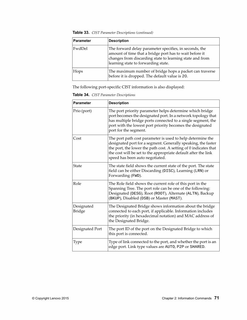
© Copyright Lenovo 2015 Chapter 2: Information Commands 71
The following port-specific CIST information is also displayed:
FwdDel The forward delay parameter specifies, in seconds, the amount of time that a bridge port has to wait before it changes from discarding state to learning state and from learning state to forwarding state.
Hops The maximum number of bridge hops a packet can traverse before it is dropped. The default value is 20.
Table 34. CIST Parameter Descriptions
Parameter Description
Prio (port) The port priority parameter helps determine which bridge port becomes the designated port. In a network topology that has multiple bridge ports connected to a single segment, the port with the lowest port priority becomes the designated port for the segment.
Cost The port path cost parameter is used to help determine the designated port for a segment. Generally speaking, the faster the port, the lower the path cost. A setting of 0 indicates that the cost will be set to the appropriate default after the link speed has been auto negotiated.
State The state field shows the current state of the port. The state field can be either Discarding (DISC), Learning (LRN) or Forwarding (FWD).
Role The Role field shows the current role of this port in the Spanning Tree. The port role can be one of the following: Designated (DESG), Root (ROOT), Alternate (ALTN), Backup (BKUP), Disabled (DSB) or Master (MAST).
Designated Bridge
The Designated Bridge shows information about the bridge connected to each port, if applicable. Information includes the priority (in hexadecimal notation) and MAC address of the Designated Bridge.
Designated Port The port ID of the port on the Designated Bridge to which this port is connected.
Type Type of link connected to the port, and whether the port is an edge port. Link type values are AUTO, P2P or SHARED.
Table 33. CIST Parameter Descriptions (continued)
Parameter Description
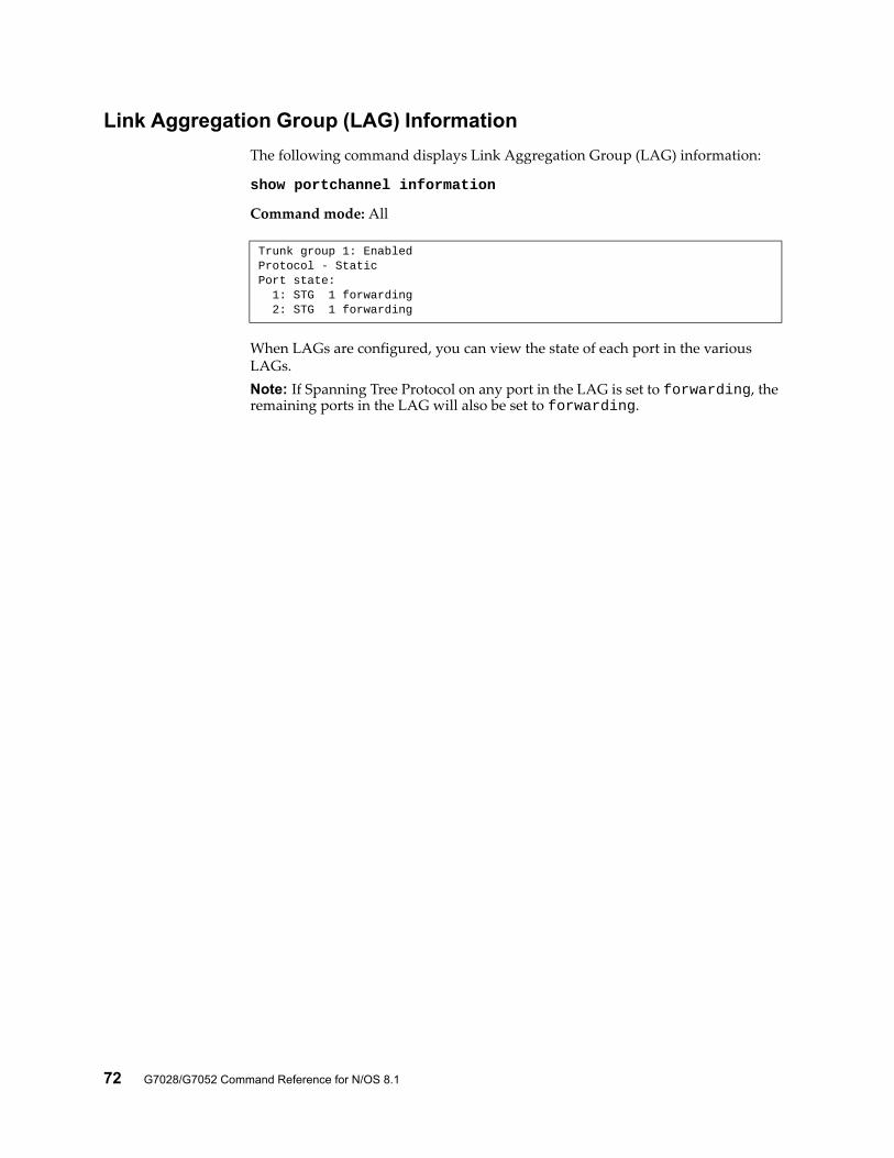
72 G7028/G7052 Command Reference for N/OS 8.1
Link Aggregation Group (LAG) Information
The following command displays Link Aggregation Group (LAG) information:
show portchannel information
Command mode: All
When LAGs are configured, you can view the state of each port in the various LAGs.Note: If Spanning Tree Protocol on any port in the LAG is set to forwarding, the remaining ports in the LAG will also be set to forwarding.
Trunk group 1: EnabledProtocol - Static Port state: 1: STG 1 forwarding 2: STG 1 forwarding
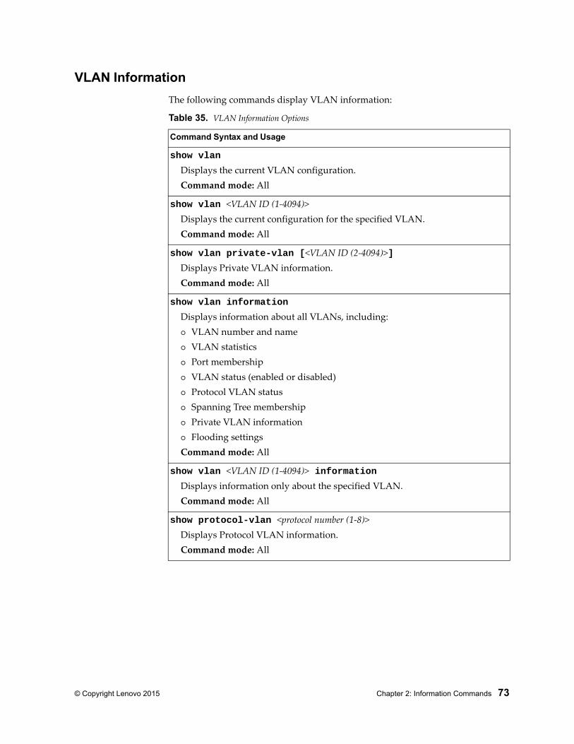
© Copyright Lenovo 2015 Chapter 2: Information Commands 73
VLAN Information
The following commands display VLAN information:
Table 35. VLAN Information Options
Command Syntax and Usage
show vlan
Displays the current VLAN configuration.Command mode: All
show vlan <VLAN ID (1-4094)>Displays the current configuration for the specified VLAN.Command mode: All
show vlan private-vlan [<VLAN ID (2-4094)>]Displays Private VLAN information.Command mode: All
show vlan information
Displays information about all VLANs, including: VLAN number and name VLAN statistics Port membership VLAN status (enabled or disabled) Protocol VLAN status Spanning Tree membership Private VLAN information Flooding settingsCommand mode: All
show vlan <VLAN ID (1-4094)> informationDisplays information only about the specified VLAN.Command mode: All
show protocol-vlan <protocol number (1-8)>Displays Protocol VLAN information.Command mode: All
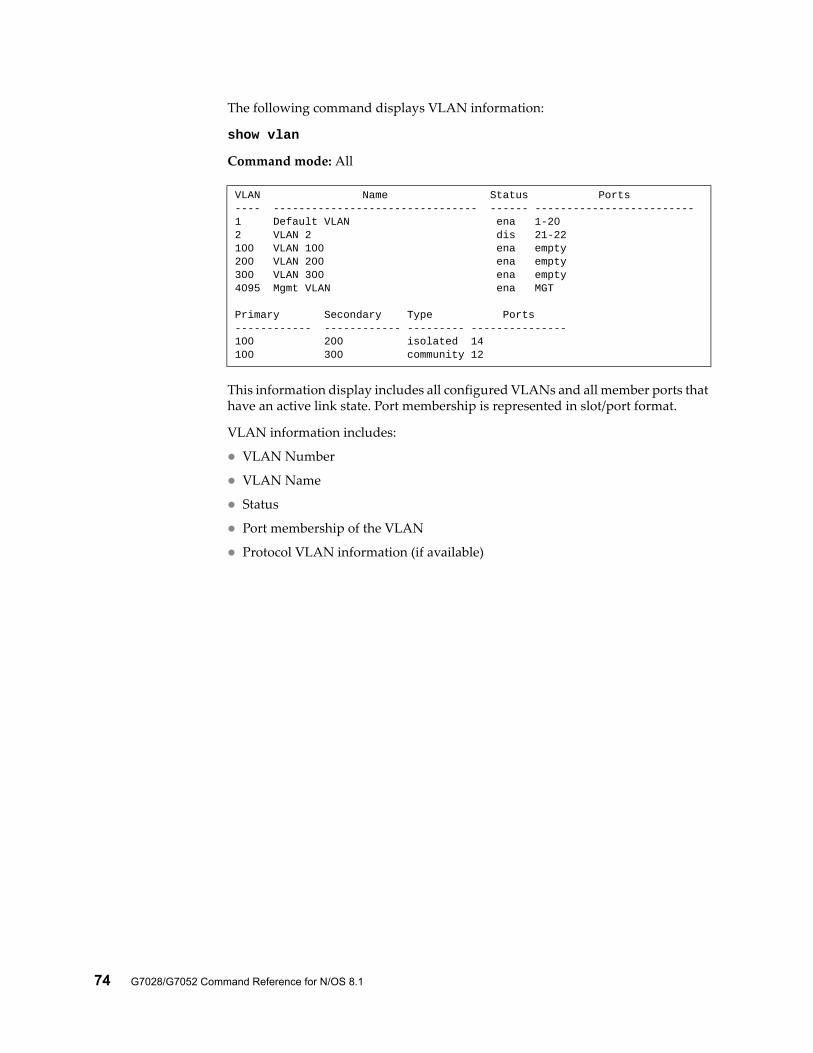
74 G7028/G7052 Command Reference for N/OS 8.1
The following command displays VLAN information:
show vlan
Command mode: All
This information display includes all configured VLANs and all member ports that have an active link state. Port membership is represented in slot/port format.
VLAN information includes:
VLAN Number
VLAN Name
Status
Port membership of the VLAN
Protocol VLAN information (if available)
VLAN Name Status Ports---- -------------------------------- ------ -------------------------1 Default VLAN ena 1-202 VLAN 2 dis 21-22100 VLAN 100 ena empty200 VLAN 200 ena empty300 VLAN 300 ena empty4095 Mgmt VLAN ena MGT
Primary Secondary Type Ports------------ ------------ --------- ---------------100 200 isolated 14100 300 community 12
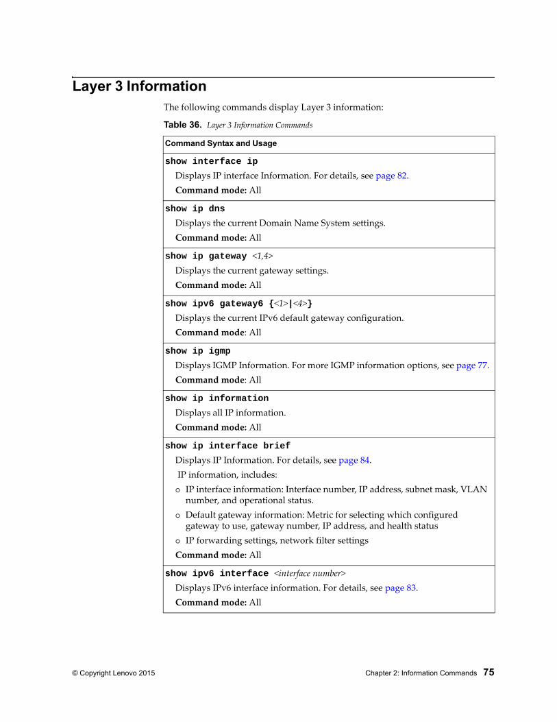
© Copyright Lenovo 2015 Chapter 2: Information Commands 75
Layer 3 InformationThe following commands display Layer 3 information:
Table 36. Layer 3 Information Commands
Command Syntax and Usage
show interface ip
Displays IP interface Information. For details, see page 82.Command mode: All
show ip dns
Displays the current Domain Name System settings.Command mode: All
show ip gateway <1,4>Displays the current gateway settings.Command mode: All
show ipv6 gateway6 {<1>|<4>}Displays the current IPv6 default gateway configuration.Command mode: All
show ip igmp
Displays IGMP Information. For more IGMP information options, see page 77.Command mode: All
show ip information
Displays all IP information.Command mode: All
show ip interface brief
Displays IP Information. For details, see page 84. IP information, includes: IP interface information: Interface number, IP address, subnet mask, VLAN
number, and operational status. Default gateway information: Metric for selecting which configured
gateway to use, gateway number, IP address, and health status IP forwarding settings, network filter settingsCommand mode: All
show ipv6 interface <interface number>Displays IPv6 interface information. For details, see page 83.Command mode: All
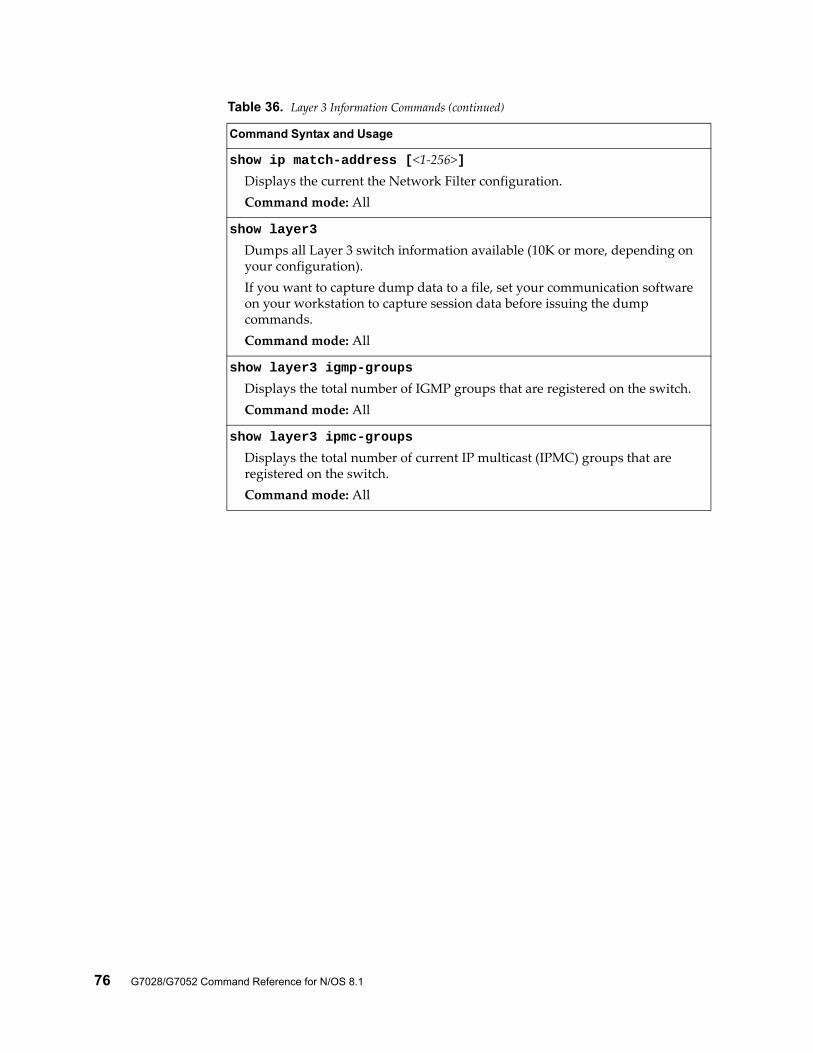
76 G7028/G7052 Command Reference for N/OS 8.1
show ip match-address [<1-256>]Displays the current the Network Filter configuration.Command mode: All
show layer3
Dumps all Layer 3 switch information available (10K or more, depending on your configuration).If you want to capture dump data to a file, set your communication software on your workstation to capture session data before issuing the dump commands.Command mode: All
show layer3 igmp-groups
Displays the total number of IGMP groups that are registered on the switch.Command mode: All
show layer3 ipmc-groups
Displays the total number of current IP multicast (IPMC) groups that are registered on the switch.Command mode: All
Table 36. Layer 3 Information Commands (continued)
Command Syntax and Usage
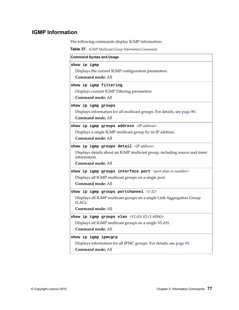
© Copyright Lenovo 2015 Chapter 2: Information Commands 77
IGMP Information
The following commands display IGMP information:
Table 37. IGMP Multicast Group Information Commands
Command Syntax and Usage
show ip igmp
Displays the current IGMP configuration parameters.Command mode: All
show ip igmp filtering
Displays current IGMP Filtering parameters.Command mode: All
show ip igmp groups
Displays information for all multicast groups. For details, see page 80.Command mode: All
show ip igmp groups address <IP address>Displays a single IGMP multicast group by its IP address.Command mode: All
show ip igmp groups detail <IP address>Displays details about an IGMP multicast group, including source and timer information.Command mode: All
show ip igmp groups interface port <port alias or number>Displays all IGMP multicast groups on a single port.Command mode: All
show ip igmp groups portchannel <1-32>Displays all IGMP multicast groups on a single Link Aggregation Group (LAG).Command mode: All
show ip igmp groups vlan <VLAN ID (1-4094)>Displays all IGMP multicast groups on a single VLAN.Command mode: All
show ip igmp ipmcgrp
Displays information for all IPMC groups. For details, see page 81.Command mode: All
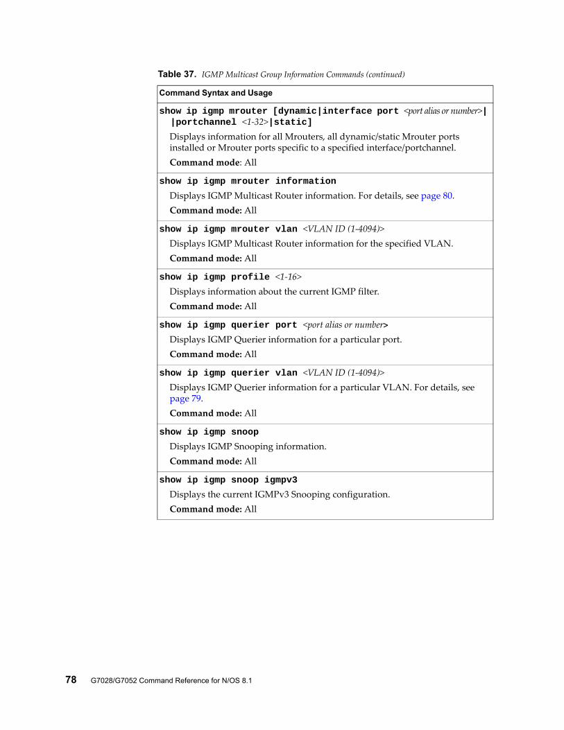
78 G7028/G7052 Command Reference for N/OS 8.1
show ip igmp mrouter [dynamic|interface port <port alias or number>| |portchannel <1-32>|static]
Displays information for all Mrouters, all dynamic/static Mrouter ports installed or Mrouter ports specific to a specified interface/portchannel.Command mode: All
show ip igmp mrouter information
Displays IGMP Multicast Router information. For details, see page 80.Command mode: All
show ip igmp mrouter vlan <VLAN ID (1-4094)>Displays IGMP Multicast Router information for the specified VLAN.Command mode: All
show ip igmp profile <1-16>Displays information about the current IGMP filter.Command mode: All
show ip igmp querier port <port alias or number>Displays IGMP Querier information for a particular port.Command mode: All
show ip igmp querier vlan <VLAN ID (1-4094)>Displays IGMP Querier information for a particular VLAN. For details, see page 79.Command mode: All
show ip igmp snoop
Displays IGMP Snooping information.Command mode: All
show ip igmp snoop igmpv3
Displays the current IGMPv3 Snooping configuration.Command mode: All
Table 37. IGMP Multicast Group Information Commands (continued)
Command Syntax and Usage
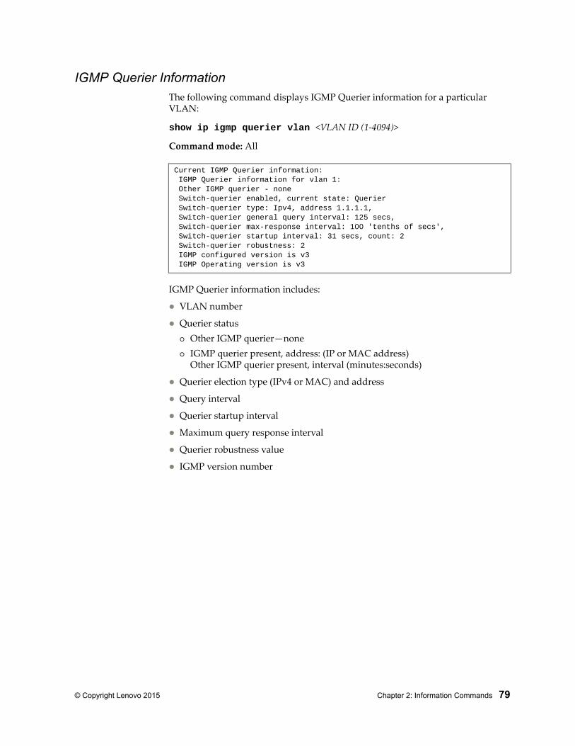
© Copyright Lenovo 2015 Chapter 2: Information Commands 79
IGMP Querier InformationThe following command displays IGMP Querier information for a particular VLAN:
show ip igmp querier vlan <VLAN ID (1-4094)>
Command mode: All
IGMP Querier information includes:
VLAN number
Querier status Other IGMP querier—none IGMP querier present, address: (IP or MAC address)
Other IGMP querier present, interval (minutes:seconds)
Querier election type (IPv4 or MAC) and address
Query interval
Querier startup interval
Maximum query response interval
Querier robustness value
IGMP version number
Current IGMP Querier information: IGMP Querier information for vlan 1: Other IGMP querier - none Switch-querier enabled, current state: Querier Switch-querier type: Ipv4, address 1.1.1.1, Switch-querier general query interval: 125 secs, Switch-querier max-response interval: 100 'tenths of secs', Switch-querier startup interval: 31 secs, count: 2 Switch-querier robustness: 2 IGMP configured version is v3 IGMP Operating version is v3
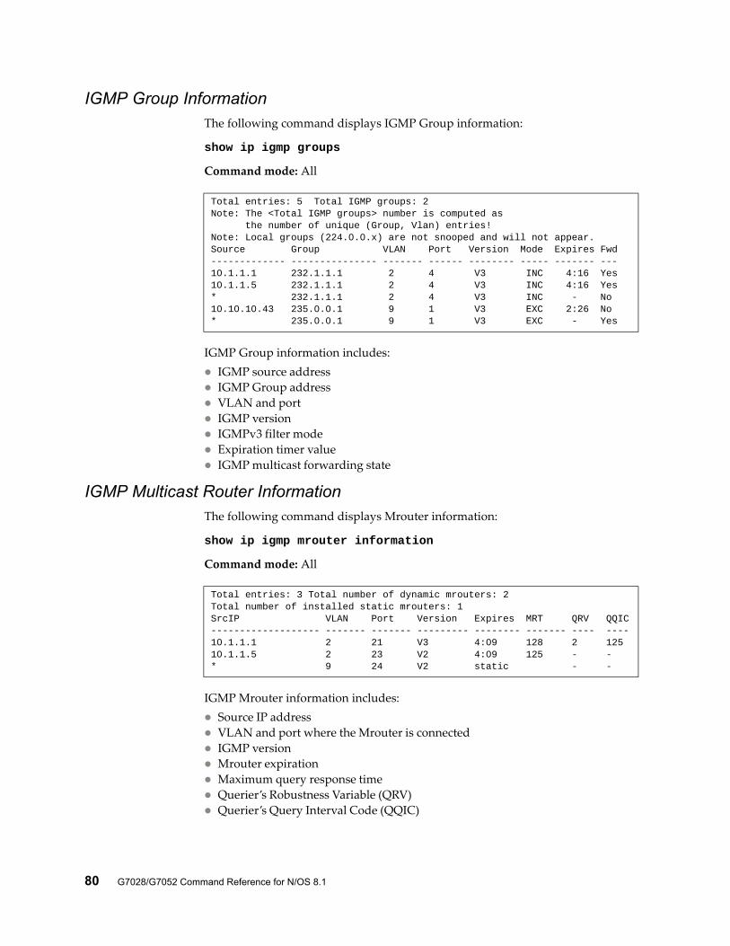
80 G7028/G7052 Command Reference for N/OS 8.1
IGMP Group InformationThe following command displays IGMP Group information:
show ip igmp groups
Command mode: All
IGMP Group information includes: IGMP source address IGMP Group address VLAN and port IGMP version IGMPv3 filter mode Expiration timer value IGMP multicast forwarding state
IGMP Multicast Router InformationThe following command displays Mrouter information:
show ip igmp mrouter information
Command mode: All
IGMP Mrouter information includes: Source IP address VLAN and port where the Mrouter is connected IGMP version Mrouter expiration Maximum query response time Querier’s Robustness Variable (QRV) Querier’s Query Interval Code (QQIC)
Total entries: 5 Total IGMP groups: 2Note: The <Total IGMP groups> number is computed as the number of unique (Group, Vlan) entries!Note: Local groups (224.0.0.x) are not snooped and will not appear.Source Group VLAN Port Version Mode Expires Fwd------------- --------------- ------- ------ -------- ----- ------- ---10.1.1.1 232.1.1.1 2 4 V3 INC 4:16 Yes10.1.1.5 232.1.1.1 2 4 V3 INC 4:16 Yes* 232.1.1.1 2 4 V3 INC - No10.10.10.43 235.0.0.1 9 1 V3 EXC 2:26 No* 235.0.0.1 9 1 V3 EXC - Yes
Total entries: 3 Total number of dynamic mrouters: 2Total number of installed static mrouters: 1SrcIP VLAN Port Version Expires MRT QRV QQIC------------------- ------- ------- --------- -------- ------- ---- ----10.1.1.1 2 21 V3 4:09 128 2 12510.1.1.5 2 23 V2 4:09 125 - -* 9 24 V2 static - -
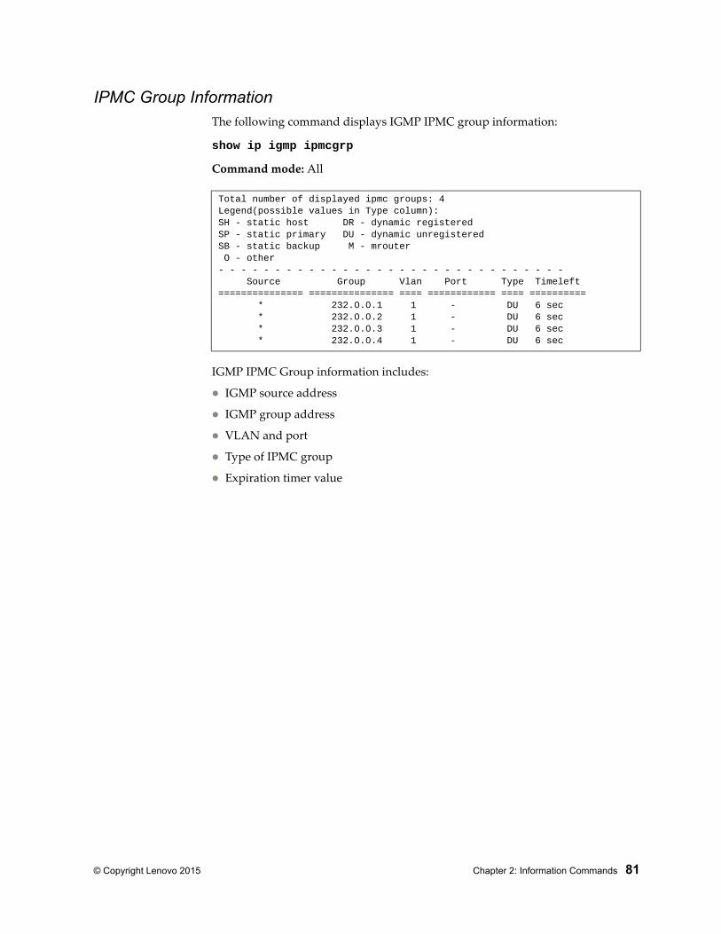
© Copyright Lenovo 2015 Chapter 2: Information Commands 81
IPMC Group InformationThe following command displays IGMP IPMC group information:
show ip igmp ipmcgrp
Command mode: All
IGMP IPMC Group information includes:
IGMP source address
IGMP group address
VLAN and port
Type of IPMC group
Expiration timer value
Total number of displayed ipmc groups: 4Legend(possible values in Type column):SH - static host DR - dynamic registeredSP - static primary DU - dynamic unregisteredSB - static backup M - mrouter O - other- - - - - - - - - - - - - - - - - - - - - - - - - - - - - - - Source Group Vlan Port Type Timeleft=============== =============== ==== ============ ==== ========== * 232.0.0.1 1 - DU 6 sec * 232.0.0.2 1 - DU 6 sec * 232.0.0.3 1 - DU 6 sec * 232.0.0.4 1 - DU 6 sec
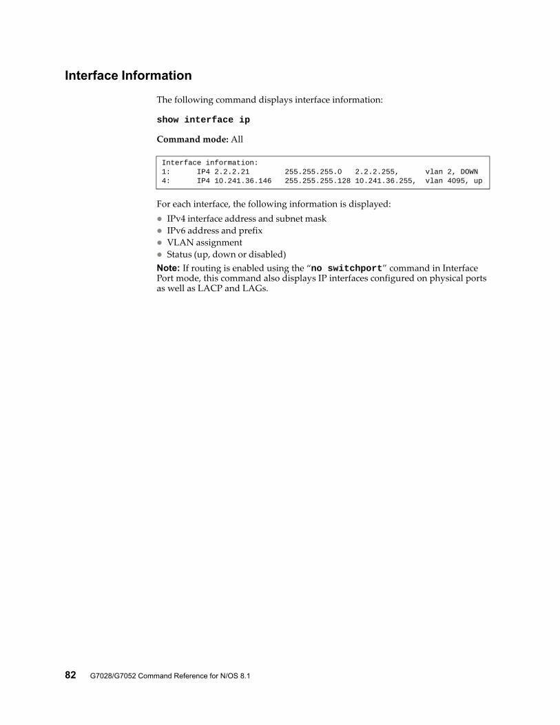
82 G7028/G7052 Command Reference for N/OS 8.1
Interface Information
The following command displays interface information:
show interface ip
Command mode: All
For each interface, the following information is displayed: IPv4 interface address and subnet mask IPv6 address and prefix VLAN assignment Status (up, down or disabled)Note: If routing is enabled using the “no switchport” command in Interface Port mode, this command also displays IP interfaces configured on physical ports as well as LACP and LAGs.
Interface information:1: IP4 2.2.2.21 255.255.255.0 2.2.2.255, vlan 2, DOWN 4: IP4 10.241.36.146 255.255.255.128 10.241.36.255, vlan 4095, up
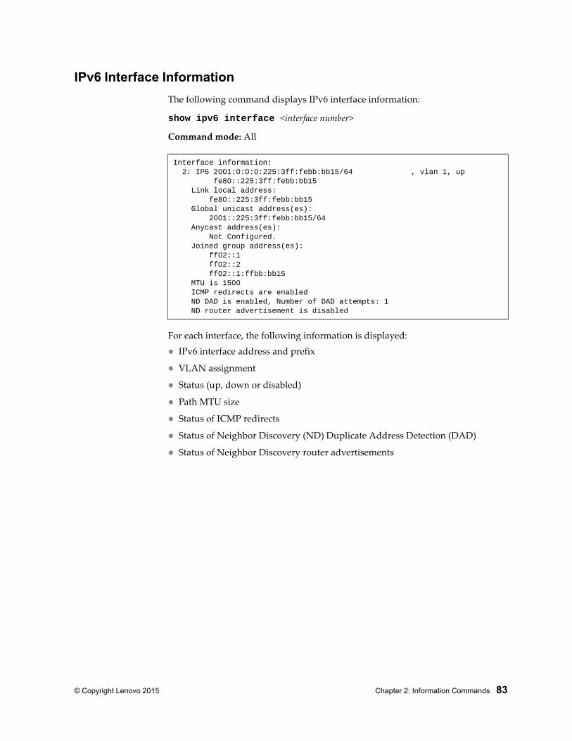
© Copyright Lenovo 2015 Chapter 2: Information Commands 83
IPv6 Interface Information
The following command displays IPv6 interface information:
show ipv6 interface <interface number>
Command mode: All
For each interface, the following information is displayed:
IPv6 interface address and prefix
VLAN assignment
Status (up, down or disabled)
Path MTU size
Status of ICMP redirects
Status of Neighbor Discovery (ND) Duplicate Address Detection (DAD)
Status of Neighbor Discovery router advertisements
Interface information: 2: IP6 2001:0:0:0:225:3ff:febb:bb15/64 , vlan 1, up fe80::225:3ff:febb:bb15 Link local address: fe80::225:3ff:febb:bb15 Global unicast address(es): 2001::225:3ff:febb:bb15/64 Anycast address(es): Not Configured. Joined group address(es): ff02::1 ff02::2 ff02::1:ffbb:bb15 MTU is 1500 ICMP redirects are enabled ND DAD is enabled, Number of DAD attempts: 1 ND router advertisement is disabled
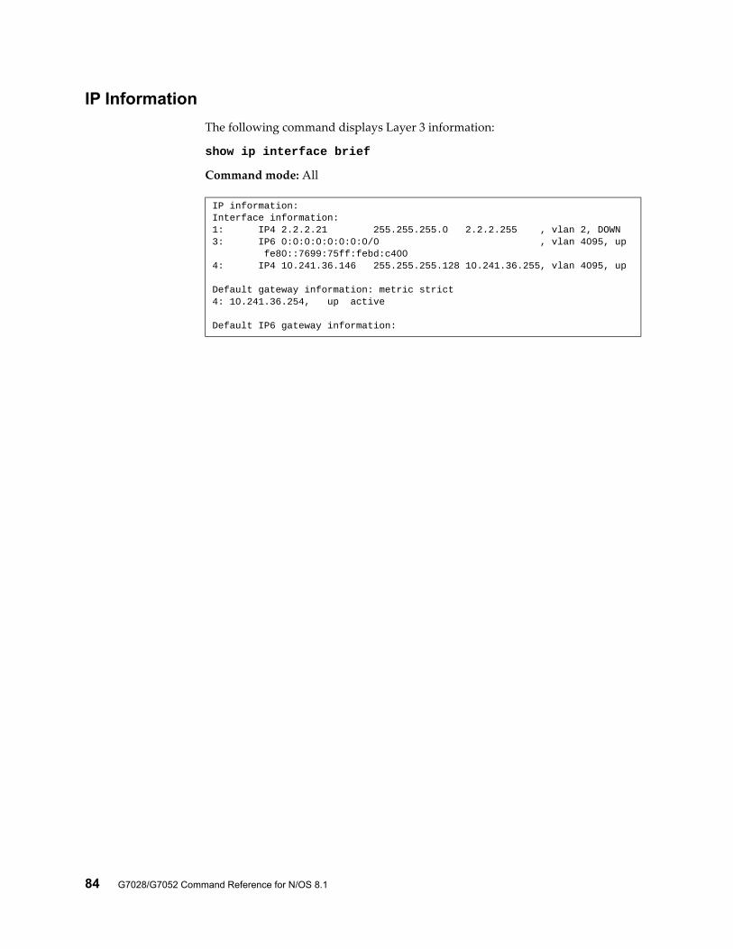
84 G7028/G7052 Command Reference for N/OS 8.1
IP Information
The following command displays Layer 3 information:
show ip interface brief
Command mode: All
IP information:Interface information:1: IP4 2.2.2.21 255.255.255.0 2.2.2.255 , vlan 2, DOWN3: IP6 0:0:0:0:0:0:0:0/0 , vlan 4095, up fe80::7699:75ff:febd:c4004: IP4 10.241.36.146 255.255.255.128 10.241.36.255, vlan 4095, up
Default gateway information: metric strict4: 10.241.36.254, up active
Default IP6 gateway information:

© Copyright Lenovo 2015 Chapter 2: Information Commands 85
IP information includes:
IP interface information: Interface number, IP address, subnet mask, broadcast address, VLAN number and operational status.
Default gateway information: Metric for selecting which configured gateway to use, gateway number, IP address and health status
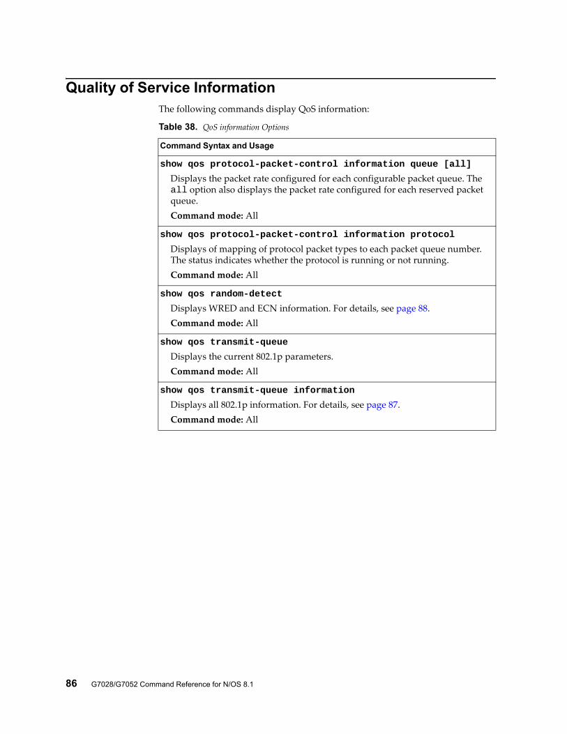
86 G7028/G7052 Command Reference for N/OS 8.1
Quality of Service InformationThe following commands display QoS information:
Table 38. QoS information Options
Command Syntax and Usage
show qos protocol-packet-control information queue [all]
Displays the packet rate configured for each configurable packet queue. The all option also displays the packet rate configured for each reserved packet queue.Command mode: All
show qos protocol-packet-control information protocol
Displays of mapping of protocol packet types to each packet queue number. The status indicates whether the protocol is running or not running.Command mode: All
show qos random-detect
Displays WRED and ECN information. For details, see page 88.Command mode: All
show qos transmit-queue
Displays the current 802.1p parameters.Command mode: All
show qos transmit-queue information
Displays all 802.1p information. For details, see page 87.Command mode: All
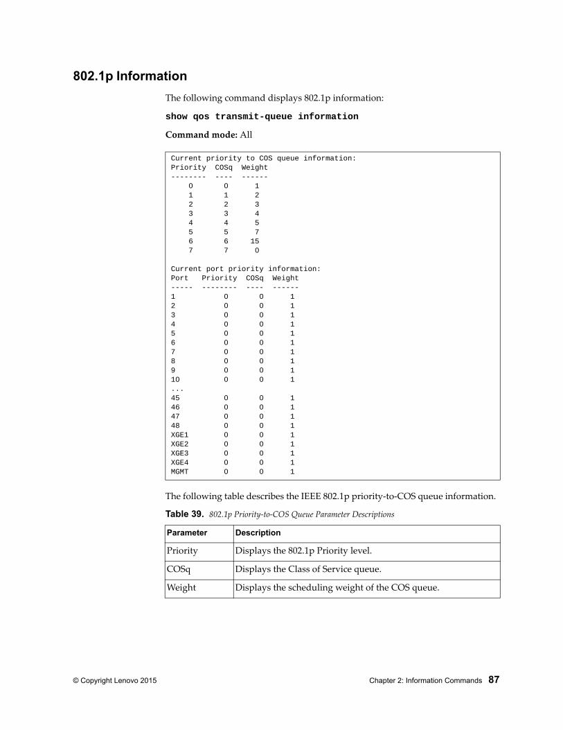
© Copyright Lenovo 2015 Chapter 2: Information Commands 87
802.1p Information
The following command displays 802.1p information:
show qos transmit-queue information
Command mode: All
The following table describes the IEEE 802.1p priority-to-COS queue information.
Current priority to COS queue information:Priority COSq Weight-------- ---- ------ 0 0 1 1 1 2 2 2 3 3 3 4 4 4 5 5 5 7 6 6 15 7 7 0
Current port priority information:Port Priority COSq Weight----- -------- ---- ------1 0 0 12 0 0 13 0 0 14 0 0 15 0 0 16 0 0 17 0 0 18 0 0 19 0 0 110 0 0 1...45 0 0 146 0 0 147 0 0 148 0 0 1XGE1 0 0 1XGE2 0 0 1XGE3 0 0 1XGE4 0 0 1MGMT 0 0 1
Table 39. 802.1p Priority-to-COS Queue Parameter Descriptions
Parameter Description
Priority Displays the 802.1p Priority level.
COSq Displays the Class of Service queue.
Weight Displays the scheduling weight of the COS queue.
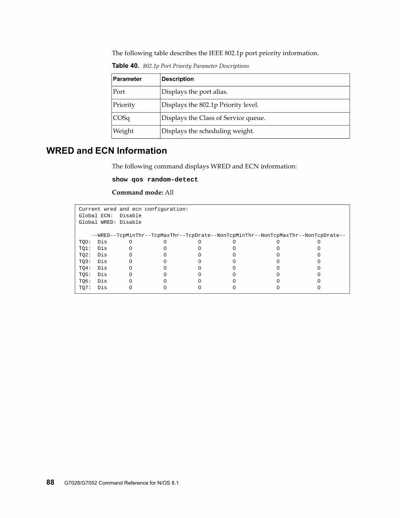
88 G7028/G7052 Command Reference for N/OS 8.1
The following table describes the IEEE 802.1p port priority information.
WRED and ECN Information
The following command displays WRED and ECN information:
show qos random-detect
Command mode: All
Table 40. 802.1p Port Priority Parameter Descriptions
Parameter Description
Port Displays the port alias.
Priority Displays the 802.1p Priority level.
COSq Displays the Class of Service queue.
Weight Displays the scheduling weight.
Current wred and ecn configuration:Global ECN: DisableGlobal WRED: Disable
--WRED--TcpMinThr--TcpMaxThr--TcpDrate--NonTcpMinThr--NonTcpMaxThr--NonTcpDrate--TQ0: Dis 0 0 0 0 0 0TQ1: Dis 0 0 0 0 0 0TQ2: Dis 0 0 0 0 0 0TQ3: Dis 0 0 0 0 0 0TQ4: Dis 0 0 0 0 0 0TQ5: Dis 0 0 0 0 0 0TQ6: Dis 0 0 0 0 0 0TQ7: Dis 0 0 0 0 0 0
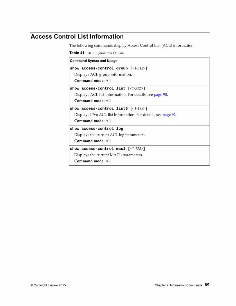
© Copyright Lenovo 2015 Chapter 2: Information Commands 89
Access Control List InformationThe following commands display Access Control List (ACL) information:
Table 41. ACL Information Options
Command Syntax and Usage
show access-control group [<1-512>]Displays ACL group information.Command mode: All
show access-control list [<1-512>]Displays ACL list information. For details, see page 90.Command mode: All
show access-control list6 [<1-128>]Displays IPv6 ACL list information. For details, see page 92.Command mode: All
show access-control log
Displays the current ACL log parameters.Command mode: All
show access-control macl [<1-128>]Displays the current MACL parameters.Command mode: All
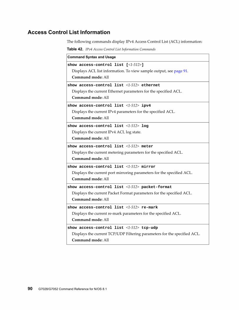
90 G7028/G7052 Command Reference for N/OS 8.1
Access Control List Information
The following commands display IPv4 Access Control List (ACL) information:
Table 42. IPv4 Access Control List Information Commands
Command Syntax and Usage
show access-control list [<1-512>]Displays ACL list information. To view sample output, see page 91.Command mode: All
show access-control list <1-512> ethernetDisplays the current Ethernet parameters for the specified ACL.Command mode: All
show access-control list <1-512> ipv4Displays the current IPv4 parameters for the specified ACL.Command mode: All
show access-control list <1-512> logDisplays the current IPv4 ACL log state.Command mode: All
show access-control list <1-512> meterDisplays the current metering parameters for the specified ACL.Command mode: All
show access-control list <1-512> mirrorDisplays the current port mirroring parameters for the specified ACL.Command mode: All
show access-control list <1-512> packet-formatDisplays the current Packet Format parameters for the specified ACL.Command mode: All
show access-control list <1-512> re-markDisplays the current re-mark parameters for the specified ACL.Command mode: All
show access-control list <1-512> tcp-udpDisplays the current TCP/UDP Filtering parameters for the specified ACL.Command mode: All
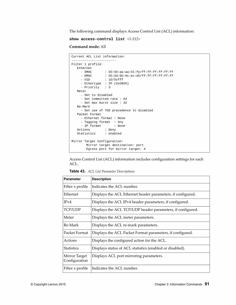
© Copyright Lenovo 2015 Chapter 2: Information Commands 91
The following command displays Access Control List (ACL) information:
show access-control list <1-512>
Command mode: All
Access Control List (ACL) information includes configuration settings for each ACL.
Current ACL List information:------------------------Filter 1 profile: Ethernet - SMAC : 00:00:aa:aa:01:fe/ff:ff:ff:ff:ff:ff - DMAC : 00:0d:60:9c:ec:d5/ff:ff:ff:ff:ff:ff - VID : 10/0xfff - Ethertype : IP (0x0800) - Priority : 3 Meter - Set to disabled - Set committed rate : 64 - Set max burst size : 32 Re-Mark - Set use of TOS precedence to disabled Packet Format - Ethernet format : None - Tagging format : Any - IP format : None Actions : Deny Statistics : enabled
Mirror Target Configuration: Mirror target destination: port Egress port for mirror target: 4
Table 43. ACL List Parameter Descriptions
Parameter Description
Filter x profile Indicates the ACL number.
Ethernet Displays the ACL Ethernet header parameters, if configured.
IPv4 Displays the ACL IPv4 header parameters, if configured.
TCP/UDP Displays the ACL TCP/UDP header parameters, if configured.
Meter Displays the ACL meter parameters.
Re-Mark Displays the ACL re-mark parameters.
Packet Format Displays the ACL Packet Format parameters, if configured.
Actions Displays the configured action for the ACL.
Statistics Displays status of ACL statistics (enabled or disabled).
Mirror TargetConfiguration
Displays ACL port mirroring parameters.
Filter x profile Indicates the ACL number.
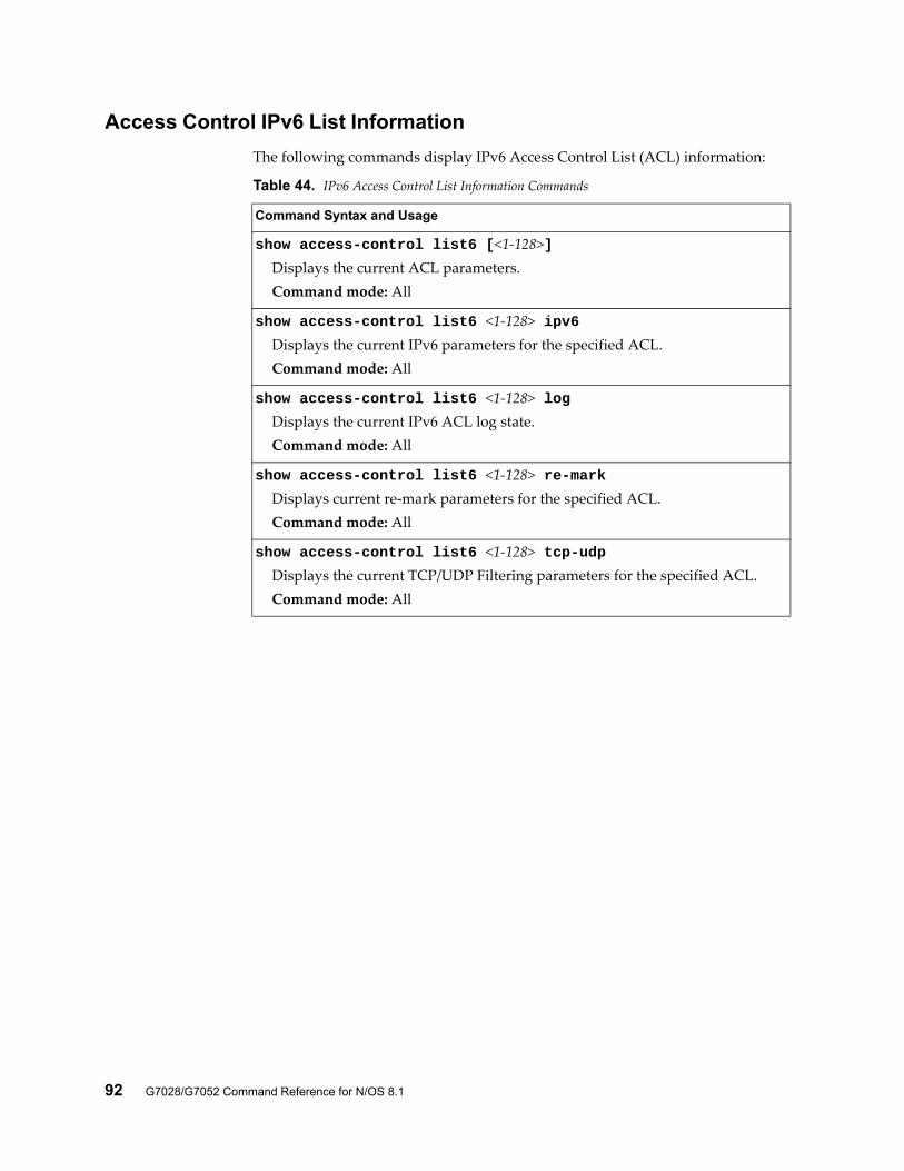
92 G7028/G7052 Command Reference for N/OS 8.1
Access Control IPv6 List Information
The following commands display IPv6 Access Control List (ACL) information:
Table 44. IPv6 Access Control List Information Commands
Command Syntax and Usage
show access-control list6 [<1-128>]Displays the current ACL parameters.Command mode: All
show access-control list6 <1-128> ipv6Displays the current IPv6 parameters for the specified ACL.Command mode: All
show access-control list6 <1-128> logDisplays the current IPv6 ACL log state.Command mode: All
show access-control list6 <1-128> re-markDisplays current re-mark parameters for the specified ACL.Command mode: All
show access-control list6 <1-128> tcp-udpDisplays the current TCP/UDP Filtering parameters for the specified ACL.Command mode: All
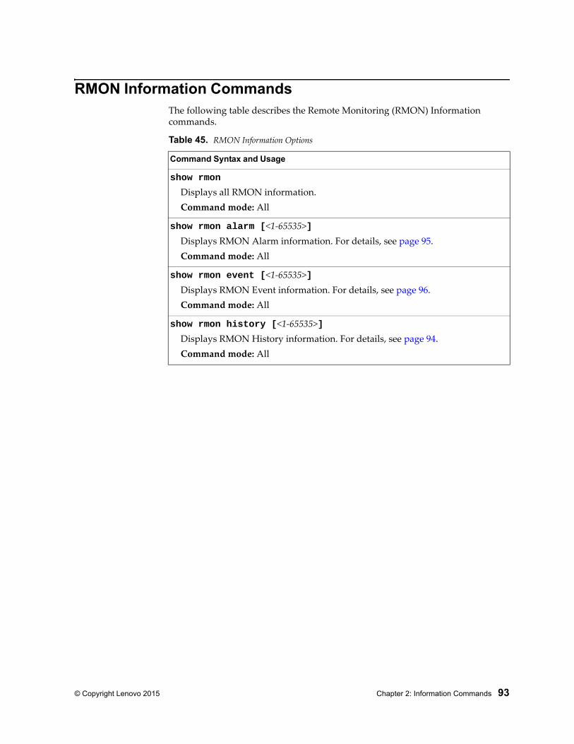
© Copyright Lenovo 2015 Chapter 2: Information Commands 93
RMON Information CommandsThe following table describes the Remote Monitoring (RMON) Information commands.
Table 45. RMON Information Options
Command Syntax and Usage
show rmon
Displays all RMON information.Command mode: All
show rmon alarm [<1-65535>]Displays RMON Alarm information. For details, see page 95.Command mode: All
show rmon event [<1-65535>]Displays RMON Event information. For details, see page 96.Command mode: All
show rmon history [<1-65535>]Displays RMON History information. For details, see page 94.Command mode: All
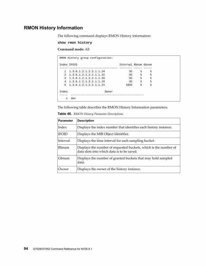
94 G7028/G7052 Command Reference for N/OS 8.1
RMON History Information
The following command displays RMON History information:
show rmon history
Command mode: All
The following table describes the RMON History Information parameters.
RMON History group configuration:
Index IFOID Interval Rbnum Gbnum----- ------------------------------ -------- ----- ----- 1 1.3.6.1.2.1.2.2.1.1.24 30 5 5 2 1.3.6.1.2.1.2.2.1.1.22 30 5 5 3 1.3.6.1.2.1.2.2.1.1.20 30 5 5 4 1.3.6.1.2.1.2.2.1.1.19 30 5 5 5 1.3.6.1.2.1.2.2.1.1.24 1800 5 5
Index Owner----- --------------------------------------------- 1 dan
Table 46. RMON History Parameter Descriptions
Parameter Description
Index Displays the index number that identifies each history instance.
IFOID Displays the MIB Object Identifier.
Interval Displays the time interval for each sampling bucket.
Rbnum Displays the number of requested buckets, which is the number of data slots into which data is to be saved.
Gbnum Displays the number of granted buckets that may hold sampled data.
Owner Displays the owner of the history instance.
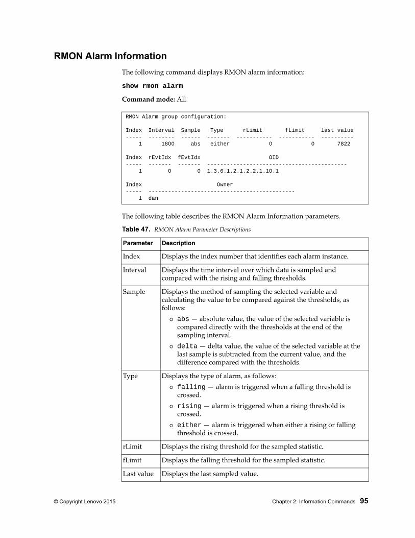
© Copyright Lenovo 2015 Chapter 2: Information Commands 95
RMON Alarm Information
The following command displays RMON alarm information:
show rmon alarm
Command mode: All
The following table describes the RMON Alarm Information parameters.
RMON Alarm group configuration:
Index Interval Sample Type rLimit fLimit last value----- -------- ------ ------- ----------- ----------- ---------- 1 1800 abs either 0 0 7822
Index rEvtIdx fEvtIdx OID----- ------- ------- ------------------------------------------- 1 0 0 1.3.6.1.2.1.2.2.1.10.1
Index Owner----- --------------------------------------------- 1 dan
Table 47. RMON Alarm Parameter Descriptions
Parameter Description
Index Displays the index number that identifies each alarm instance.
Interval Displays the time interval over which data is sampled and compared with the rising and falling thresholds.
Sample Displays the method of sampling the selected variable and calculating the value to be compared against the thresholds, as follows:
abs — absolute value, the value of the selected variable is compared directly with the thresholds at the end of the sampling interval.
delta — delta value, the value of the selected variable at the last sample is subtracted from the current value, and the difference compared with the thresholds.
Type Displays the type of alarm, as follows: falling — alarm is triggered when a falling threshold is
crossed. rising — alarm is triggered when a rising threshold is
crossed. either — alarm is triggered when either a rising or falling
threshold is crossed.
rLimit Displays the rising threshold for the sampled statistic.
fLimit Displays the falling threshold for the sampled statistic.
Last value Displays the last sampled value.
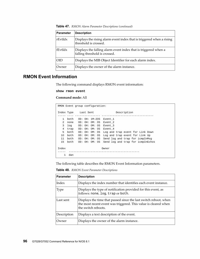
96 G7028/G7052 Command Reference for N/OS 8.1
RMON Event Information
The following command displays RMON event information:
show rmon event
Command mode: All
The following table describes the RMON Event Information parameters.
rEvtIdx Displays the rising alarm event index that is triggered when a rising threshold is crossed.
fEvtIdx Displays the falling alarm event index that is triggered when a falling threshold is crossed.
OID Displays the MIB Object Identifier for each alarm index.
Owner Displays the owner of the alarm instance.
Table 47. RMON Alarm Parameter Descriptions (continued)
Parameter Description
RMON Event group configuration:
Index Type Last Sent Description----- ---- ---------------- --------------------------------- 1 both 0D: 0H: 1M:20S Event_1 2 none 0D: 0H: 0M: 0S Event_2 3 log 0D: 0H: 0M: 0S Event_3 4 trap 0D: 0H: 0M: 0S Event_4 5 both 0D: 0H: 0M: 0S Log and trap event for Link Down 10 both 0D: 0H: 0M: 0S Log and trap event for Link Up 11 both 0D: 0H: 0M: 0S Send log and trap for icmpInMsg 15 both 0D: 0H: 0M: 0S Send log and trap for icmpInEchos
Index Owner----- --------------------------------------------- 1 dan
Table 48. RMON Event Parameter Descriptions
Parameter Description
Index Displays the index number that identifies each event instance.
Type Displays the type of notification provided for this event, as follows: none, log, trap or both.
Last sent Displays the time that passed since the last switch reboot, when the most recent event was triggered. This value is cleared when the switch reboots.
Description Displays a text description of the event.
Owner Displays the owner of the alarm instance.
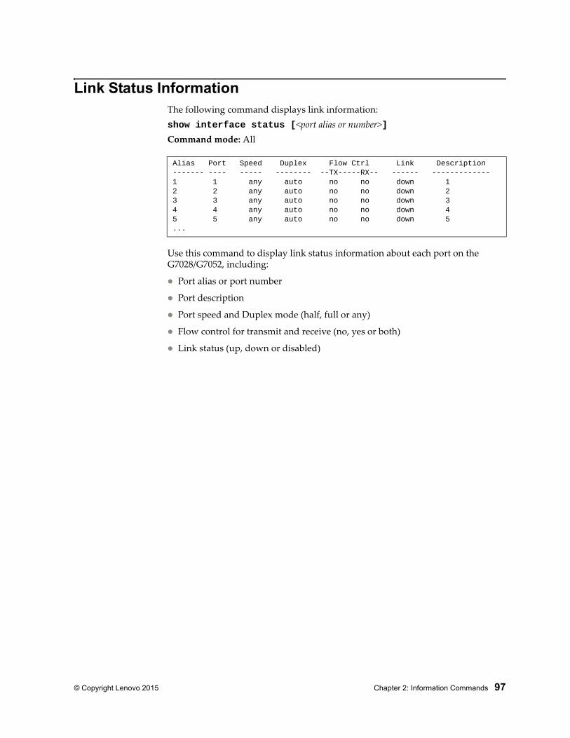
© Copyright Lenovo 2015 Chapter 2: Information Commands 97
Link Status InformationThe following command displays link information:show interface status [<port alias or number>]Command mode: All
Use this command to display link status information about each port on the G7028/G7052, including:
Port alias or port number
Port description
Port speed and Duplex mode (half, full or any)
Flow control for transmit and receive (no, yes or both)
Link status (up, down or disabled)
Alias Port Speed Duplex Flow Ctrl Link Description------- ---- ----- -------- --TX-----RX-- ------ -------------1 1 any auto no no down 12 2 any auto no no down 23 3 any auto no no down 34 4 any auto no no down 45 5 any auto no no down 5...
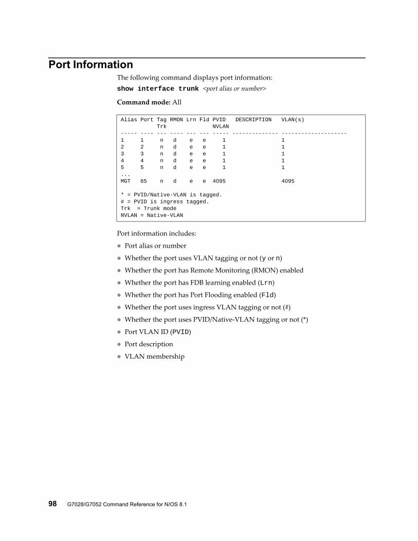
98 G7028/G7052 Command Reference for N/OS 8.1
Port InformationThe following command displays port information:show interface trunk <port alias or number>
Command mode: All
Port information includes:
Port alias or number
Whether the port uses VLAN tagging or not (y or n)
Whether the port has Remote Monitoring (RMON) enabled
Whether the port has FDB learning enabled (Lrn)
Whether the port has Port Flooding enabled (Fld)
Whether the port uses ingress VLAN tagging or not (#)
Whether the port uses PVID/Native-VLAN tagging or not (*)
Port VLAN ID (PVID)
Port description
VLAN membership
Alias Port Tag RMON Lrn Fld PVID DESCRIPTION VLAN(s) Trk NVLAN----- ---- --- ---- --- --- ----- -------------- --------------------1 1 n d e e 1 12 2 n d e e 1 13 3 n d e e 1 14 4 n d e e 1 15 5 n d e e 1 1...MGT 65 n d e e 4095 4095
* = PVID/Native-VLAN is tagged.# = PVID is ingress tagged.Trk = Trunk modeNVLAN = Native-VLAN
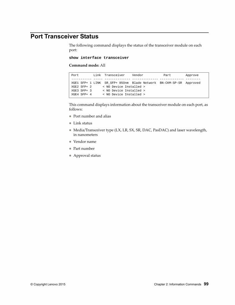
© Copyright Lenovo 2015 Chapter 2: Information Commands 99
Port Transceiver StatusThe following command displays the status of the transceiver module on each port:
show interface transceiver
Command mode: All
This command displays information about the transceiver module on each port, as follows:
Port number and alias
Link status
Media/Transceiver type (LX, LR, SX, SR, DAC, PasDAC) and laser wavelength, in nanometers
Vendor name
Part number
Approval status
Port Link Transceiver Vendor Part Approve----------- ----- -------------- -------------- ------------- --------XGE1 SFP+ 1 LINK SR_SFP+ 850nm Blade Network BN-CKM-SP-SR ApprovedXGE2 SFP+ 2 < NO Device Installed >XGE3 SFP+ 3 < NO Device Installed >XGE4 SFP+ 4 < NO Device Installed >
100 G7028/G7052 Command Reference for N/OS 8.1
Information DumpThe following command dumps switch information:
show information-dump
Command mode: All
Use the dump command to dump all switch information available (10K or more, depending on your configuration). This data is useful for tuning and debugging switch performance.
If you want to capture dump data to a file, set your communication software on your workstation to capture session data prior to issuing the dump commands.
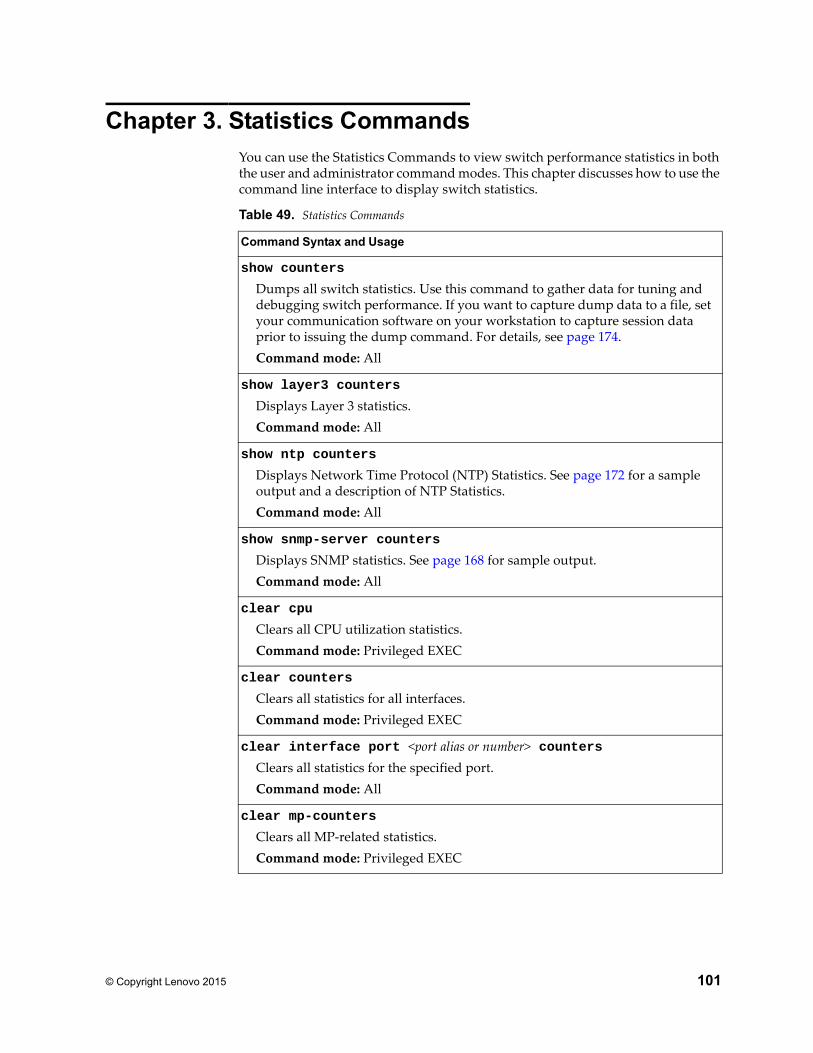
© Copyright Lenovo 2015 101
Chapter 3. Statistics CommandsYou can use the Statistics Commands to view switch performance statistics in both the user and administrator command modes. This chapter discusses how to use the command line interface to display switch statistics.
Table 49. Statistics Commands
Command Syntax and Usage
show counters
Dumps all switch statistics. Use this command to gather data for tuning and debugging switch performance. If you want to capture dump data to a file, set your communication software on your workstation to capture session data prior to issuing the dump command. For details, see page 174.Command mode: All
show layer3 counters
Displays Layer 3 statistics.Command mode: All
show ntp counters
Displays Network Time Protocol (NTP) Statistics. See page 172 for a sample output and a description of NTP Statistics.Command mode: All
show snmp-server counters
Displays SNMP statistics. See page 168 for sample output.Command mode: All
clear cpu
Clears all CPU utilization statistics.Command mode: Privileged EXEC
clear counters
Clears all statistics for all interfaces.Command mode: Privileged EXEC
clear interface port <port alias or number> countersClears all statistics for the specified port.Command mode: All
clear mp-counters
Clears all MP-related statistics.Command mode: Privileged EXEC
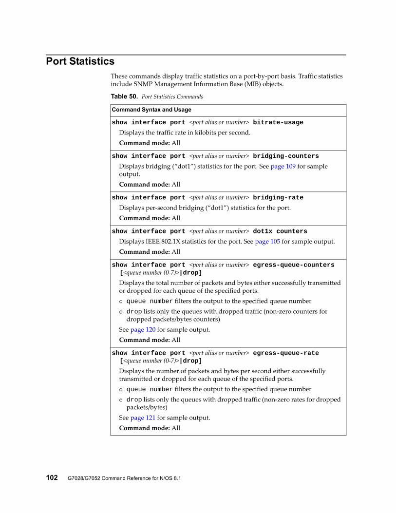
102 G7028/G7052 Command Reference for N/OS 8.1
Port StatisticsThese commands display traffic statistics on a port-by-port basis. Traffic statistics include SNMP Management Information Base (MIB) objects.
Table 50. Port Statistics Commands
Command Syntax and Usage
show interface port <port alias or number> bitrate-usageDisplays the traffic rate in kilobits per second.Command mode: All
show interface port <port alias or number> bridging-countersDisplays bridging (“dot1”) statistics for the port. See page 109 for sample output.Command mode: All
show interface port <port alias or number> bridging-rateDisplays per-second bridging (“dot1”) statistics for the port.Command mode: All
show interface port <port alias or number> dot1x countersDisplays IEEE 802.1X statistics for the port. See page 105 for sample output.Command mode: All
show interface port <port alias or number> egress-queue-counters [<queue number (0-7)>|drop]
Displays the total number of packets and bytes either successfully transmitted or dropped for each queue of the specified ports. queue number filters the output to the specified queue number drop lists only the queues with dropped traffic (non-zero counters for
dropped packets/bytes counters)See page 120 for sample output.Command mode: All
show interface port <port alias or number> egress-queue-rate [<queue number (0-7)>|drop]
Displays the number of packets and bytes per second either successfully transmitted or dropped for each queue of the specified ports. queue number filters the output to the specified queue number drop lists only the queues with dropped traffic (non-zero rates for dropped
packets/bytes)See page 121 for sample output.Command mode: All
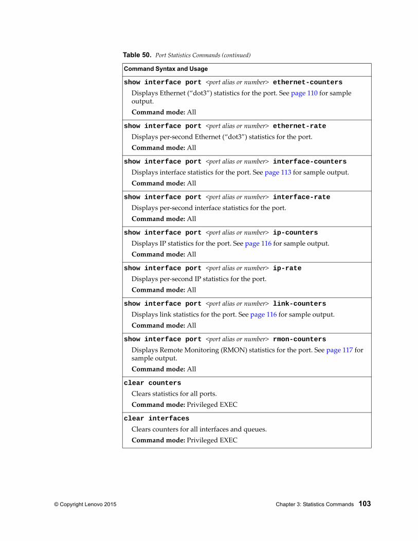
© Copyright Lenovo 2015 Chapter 3: Statistics Commands 103
show interface port <port alias or number> ethernet-countersDisplays Ethernet (“dot3”) statistics for the port. See page 110 for sample output.Command mode: All
show interface port <port alias or number> ethernet-rateDisplays per-second Ethernet (“dot3”) statistics for the port.Command mode: All
show interface port <port alias or number> interface-countersDisplays interface statistics for the port. See page 113 for sample output.Command mode: All
show interface port <port alias or number> interface-rateDisplays per-second interface statistics for the port.Command mode: All
show interface port <port alias or number> ip-countersDisplays IP statistics for the port. See page 116 for sample output.Command mode: All
show interface port <port alias or number> ip-rateDisplays per-second IP statistics for the port.Command mode: All
show interface port <port alias or number> link-countersDisplays link statistics for the port. See page 116 for sample output.Command mode: All
show interface port <port alias or number> rmon-countersDisplays Remote Monitoring (RMON) statistics for the port. See page 117 for sample output.Command mode: All
clear counters
Clears statistics for all ports.Command mode: Privileged EXEC
clear interfaces
Clears counters for all interfaces and queues.Command mode: Privileged EXEC
Table 50. Port Statistics Commands (continued)
Command Syntax and Usage
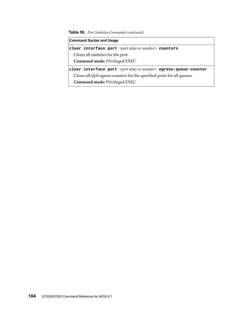
104 G7028/G7052 Command Reference for N/OS 8.1
clear interface port <port alias or number> countersClears all statistics for the port.Command mode: Privileged EXEC
clear interface port <port alias or number> egress-queue-counterClears all QoS egress counters for the specified ports for all queues.Command mode: Privileged EXEC
Table 50. Port Statistics Commands (continued)
Command Syntax and Usage
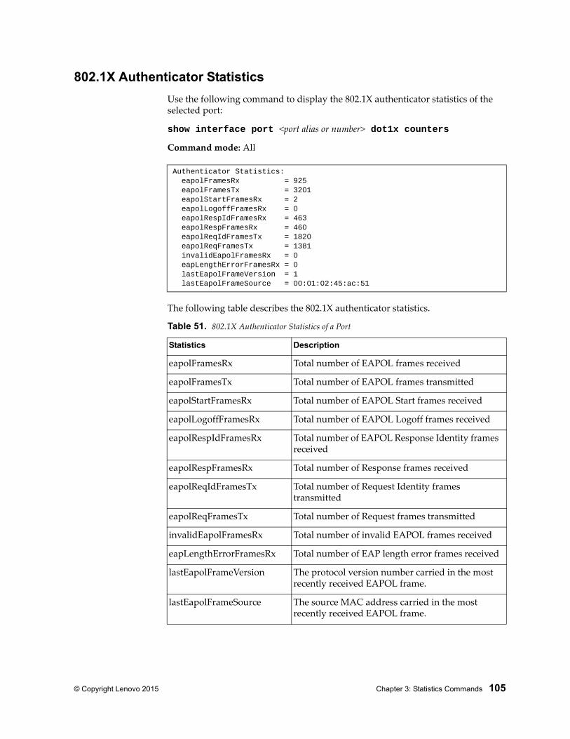
© Copyright Lenovo 2015 Chapter 3: Statistics Commands 105
802.1X Authenticator Statistics
Use the following command to display the 802.1X authenticator statistics of the selected port:
show interface port <port alias or number> dot1x counters
Command mode: All
The following table describes the 802.1X authenticator statistics.
Authenticator Statistics: eapolFramesRx = 925 eapolFramesTx = 3201 eapolStartFramesRx = 2 eapolLogoffFramesRx = 0 eapolRespIdFramesRx = 463 eapolRespFramesRx = 460 eapolReqIdFramesTx = 1820 eapolReqFramesTx = 1381 invalidEapolFramesRx = 0 eapLengthErrorFramesRx = 0 lastEapolFrameVersion = 1 lastEapolFrameSource = 00:01:02:45:ac:51
Table 51. 802.1X Authenticator Statistics of a Port
Statistics Description
eapolFramesRx Total number of EAPOL frames received
eapolFramesTx Total number of EAPOL frames transmitted
eapolStartFramesRx Total number of EAPOL Start frames received
eapolLogoffFramesRx Total number of EAPOL Logoff frames received
eapolRespIdFramesRx Total number of EAPOL Response Identity frames received
eapolRespFramesRx Total number of Response frames received
eapolReqIdFramesTx Total number of Request Identity frames transmitted
eapolReqFramesTx Total number of Request frames transmitted
invalidEapolFramesRx Total number of invalid EAPOL frames received
eapLengthErrorFramesRx Total number of EAP length error frames received
lastEapolFrameVersion The protocol version number carried in the most recently received EAPOL frame.
lastEapolFrameSource The source MAC address carried in the most recently received EAPOL frame.
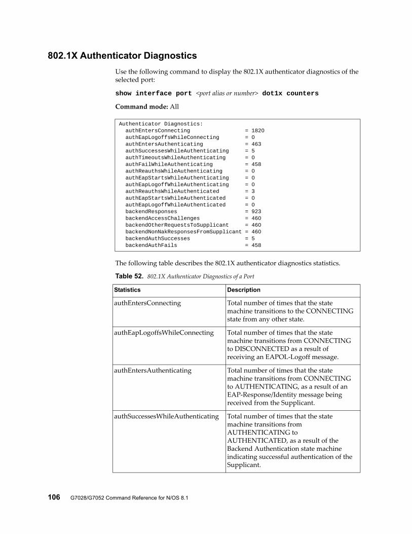
106 G7028/G7052 Command Reference for N/OS 8.1
802.1X Authenticator Diagnostics
Use the following command to display the 802.1X authenticator diagnostics of the selected port:
show interface port <port alias or number> dot1x counters
Command mode: All
The following table describes the 802.1X authenticator diagnostics statistics.
Authenticator Diagnostics: authEntersConnecting = 1820 authEapLogoffsWhileConnecting = 0 authEntersAuthenticating = 463 authSuccessesWhileAuthenticating = 5 authTimeoutsWhileAuthenticating = 0 authFailWhileAuthenticating = 458 authReauthsWhileAuthenticating = 0 authEapStartsWhileAuthenticating = 0 authEapLogoffWhileAuthenticating = 0 authReauthsWhileAuthenticated = 3 authEapStartsWhileAuthenticated = 0 authEapLogoffWhileAuthenticated = 0 backendResponses = 923 backendAccessChallenges = 460 backendOtherRequestsToSupplicant = 460 backendNonNakResponsesFromSupplicant = 460 backendAuthSuccesses = 5 backendAuthFails = 458
Table 52. 802.1X Authenticator Diagnostics of a Port
Statistics Description
authEntersConnecting Total number of times that the state machine transitions to the CONNECTING state from any other state.
authEapLogoffsWhileConnecting Total number of times that the state machine transitions from CONNECTING to DISCONNECTED as a result of receiving an EAPOL-Logoff message.
authEntersAuthenticating Total number of times that the state machine transitions from CONNECTING to AUTHENTICATING, as a result of an EAP-Response/Identity message being received from the Supplicant.
authSuccessesWhileAuthenticating Total number of times that the state machine transitions from AUTHENTICATING to AUTHENTICATED, as a result of the Backend Authentication state machine indicating successful authentication of the Supplicant.
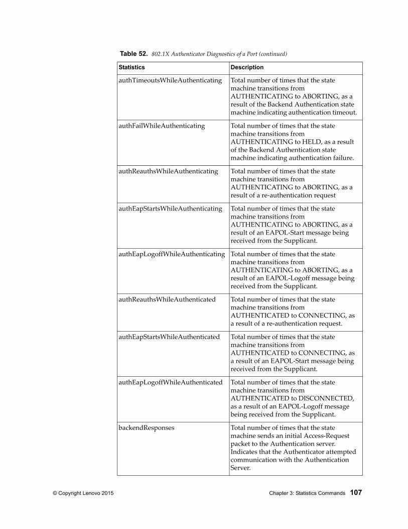
© Copyright Lenovo 2015 Chapter 3: Statistics Commands 107
authTimeoutsWhileAuthenticating Total number of times that the state machine transitions from AUTHENTICATING to ABORTING, as a result of the Backend Authentication state machine indicating authentication timeout.
authFailWhileAuthenticating Total number of times that the state machine transitions from AUTHENTICATING to HELD, as a result of the Backend Authentication state machine indicating authentication failure.
authReauthsWhileAuthenticating Total number of times that the state machine transitions from AUTHENTICATING to ABORTING, as a result of a re-authentication request
authEapStartsWhileAuthenticating Total number of times that the state machine transitions from AUTHENTICATING to ABORTING, as a result of an EAPOL-Start message being received from the Supplicant.
authEapLogoffWhileAuthenticating Total number of times that the state machine transitions from AUTHENTICATING to ABORTING, as a result of an EAPOL-Logoff message being received from the Supplicant.
authReauthsWhileAuthenticated Total number of times that the state machine transitions from AUTHENTICATED to CONNECTING, as a result of a re-authentication request.
authEapStartsWhileAuthenticated Total number of times that the state machine transitions from AUTHENTICATED to CONNECTING, as a result of an EAPOL-Start message being received from the Supplicant.
authEapLogoffWhileAuthenticated Total number of times that the state machine transitions from AUTHENTICATED to DISCONNECTED, as a result of an EAPOL-Logoff message being received from the Supplicant.
backendResponses Total number of times that the state machine sends an initial Access-Request packet to the Authentication server. Indicates that the Authenticator attempted communication with the Authentication Server.
Table 52. 802.1X Authenticator Diagnostics of a Port (continued)
Statistics Description
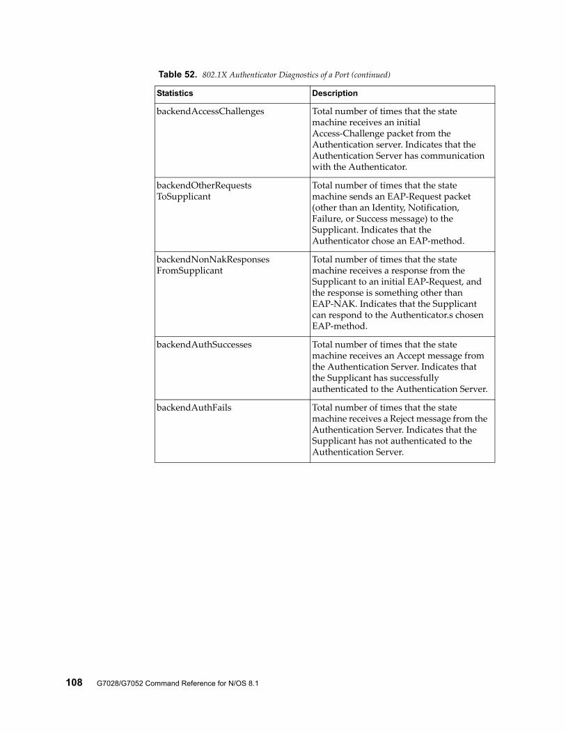
108 G7028/G7052 Command Reference for N/OS 8.1
backendAccessChallenges Total number of times that the state machine receives an initial Access-Challenge packet from the Authentication server. Indicates that the Authentication Server has communication with the Authenticator.
backendOtherRequestsToSupplicant
Total number of times that the state machine sends an EAP-Request packet (other than an Identity, Notification, Failure, or Success message) to the Supplicant. Indicates that the Authenticator chose an EAP-method.
backendNonNakResponsesFromSupplicant
Total number of times that the state machine receives a response from the Supplicant to an initial EAP-Request, and the response is something other than EAP-NAK. Indicates that the Supplicant can respond to the Authenticator.s chosen EAP-method.
backendAuthSuccesses Total number of times that the state machine receives an Accept message from the Authentication Server. Indicates that the Supplicant has successfully authenticated to the Authentication Server.
backendAuthFails Total number of times that the state machine receives a Reject message from the Authentication Server. Indicates that the Supplicant has not authenticated to the Authentication Server.
Table 52. 802.1X Authenticator Diagnostics of a Port (continued)
Statistics Description
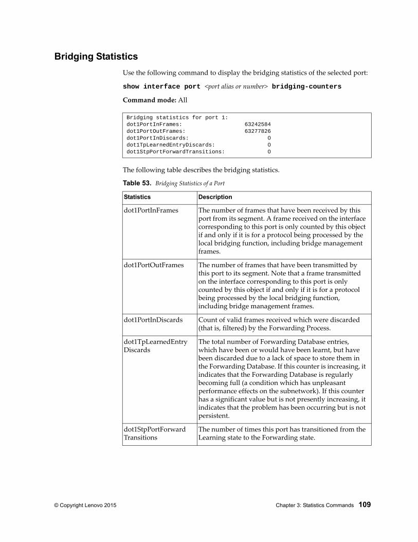
© Copyright Lenovo 2015 Chapter 3: Statistics Commands 109
Bridging Statistics
Use the following command to display the bridging statistics of the selected port:
show interface port <port alias or number> bridging-counters
Command mode: All
The following table describes the bridging statistics.
Bridging statistics for port 1:dot1PortInFrames: 63242584dot1PortOutFrames: 63277826dot1PortInDiscards: 0dot1TpLearnedEntryDiscards: 0dot1StpPortForwardTransitions: 0
Table 53. Bridging Statistics of a Port
Statistics Description
dot1PortInFrames The number of frames that have been received by this port from its segment. A frame received on the interface corresponding to this port is only counted by this object if and only if it is for a protocol being processed by the local bridging function, including bridge management frames.
dot1PortOutFrames The number of frames that have been transmitted by this port to its segment. Note that a frame transmitted on the interface corresponding to this port is only counted by this object if and only if it is for a protocol being processed by the local bridging function, including bridge management frames.
dot1PortInDiscards Count of valid frames received which were discarded (that is, filtered) by the Forwarding Process.
dot1TpLearnedEntry Discards
The total number of Forwarding Database entries, which have been or would have been learnt, but have been discarded due to a lack of space to store them in the Forwarding Database. If this counter is increasing, it indicates that the Forwarding Database is regularly becoming full (a condition which has unpleasant performance effects on the subnetwork). If this counter has a significant value but is not presently increasing, it indicates that the problem has been occurring but is not persistent.
dot1StpPortForward Transitions
The number of times this port has transitioned from the Learning state to the Forwarding state.
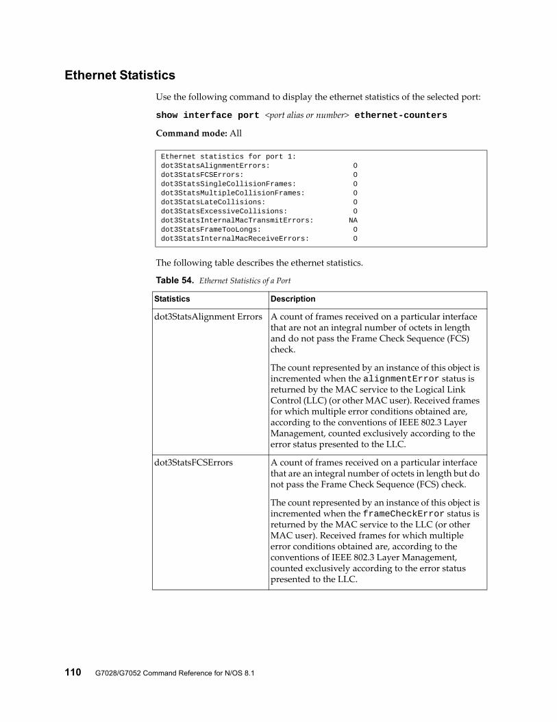
110 G7028/G7052 Command Reference for N/OS 8.1
Ethernet Statistics
Use the following command to display the ethernet statistics of the selected port:
show interface port <port alias or number> ethernet-counters
Command mode: All
The following table describes the ethernet statistics.
Ethernet statistics for port 1:dot3StatsAlignmentErrors: 0dot3StatsFCSErrors: 0dot3StatsSingleCollisionFrames: 0dot3StatsMultipleCollisionFrames: 0dot3StatsLateCollisions: 0dot3StatsExcessiveCollisions: 0dot3StatsInternalMacTransmitErrors: NAdot3StatsFrameTooLongs: 0dot3StatsInternalMacReceiveErrors: 0
Table 54. Ethernet Statistics of a Port
Statistics Description
dot3StatsAlignment Errors A count of frames received on a particular interface that are not an integral number of octets in length and do not pass the Frame Check Sequence (FCS) check.
The count represented by an instance of this object is incremented when the alignmentError status is returned by the MAC service to the Logical Link Control (LLC) (or other MAC user). Received frames for which multiple error conditions obtained are, according to the conventions of IEEE 802.3 Layer Management, counted exclusively according to the error status presented to the LLC.
dot3StatsFCSErrors A count of frames received on a particular interface that are an integral number of octets in length but do not pass the Frame Check Sequence (FCS) check.
The count represented by an instance of this object is incremented when the frameCheckError status is returned by the MAC service to the LLC (or other MAC user). Received frames for which multiple error conditions obtained are, according to the conventions of IEEE 802.3 Layer Management, counted exclusively according to the error status presented to the LLC.
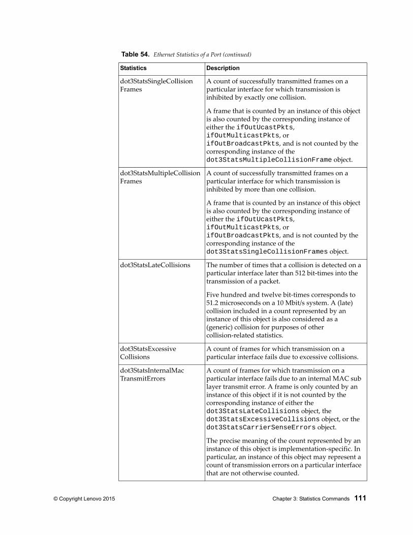
© Copyright Lenovo 2015 Chapter 3: Statistics Commands 111
dot3StatsSingleCollisionFrames
A count of successfully transmitted frames on a particular interface for which transmission is inhibited by exactly one collision.
A frame that is counted by an instance of this object is also counted by the corresponding instance of either the ifOutUcastPkts, ifOutMulticastPkts, or ifOutBroadcastPkts, and is not counted by the corresponding instance of the dot3StatsMultipleCollisionFrame object.
dot3StatsMultipleCollisionFrames
A count of successfully transmitted frames on a particular interface for which transmission is inhibited by more than one collision.
A frame that is counted by an instance of this object is also counted by the corresponding instance of either the ifOutUcastPkts, ifOutMulticastPkts, or ifOutBroadcastPkts, and is not counted by the corresponding instance of the dot3StatsSingleCollisionFrames object.
dot3StatsLateCollisions The number of times that a collision is detected on a particular interface later than 512 bit-times into the transmission of a packet.
Five hundred and twelve bit-times corresponds to 51.2 microseconds on a 10 Mbit/s system. A (late) collision included in a count represented by an instance of this object is also considered as a (generic) collision for purposes of other collision-related statistics.
dot3StatsExcessiveCollisions
A count of frames for which transmission on a particular interface fails due to excessive collisions.
dot3StatsInternalMacTransmitErrors
A count of frames for which transmission on a particular interface fails due to an internal MAC sub layer transmit error. A frame is only counted by an instance of this object if it is not counted by the corresponding instance of either the dot3StatsLateCollisions object, the dot3StatsExcessiveCollisions object, or the dot3StatsCarrierSenseErrors object.
The precise meaning of the count represented by an instance of this object is implementation-specific. In particular, an instance of this object may represent a count of transmission errors on a particular interface that are not otherwise counted.
Table 54. Ethernet Statistics of a Port (continued)
Statistics Description
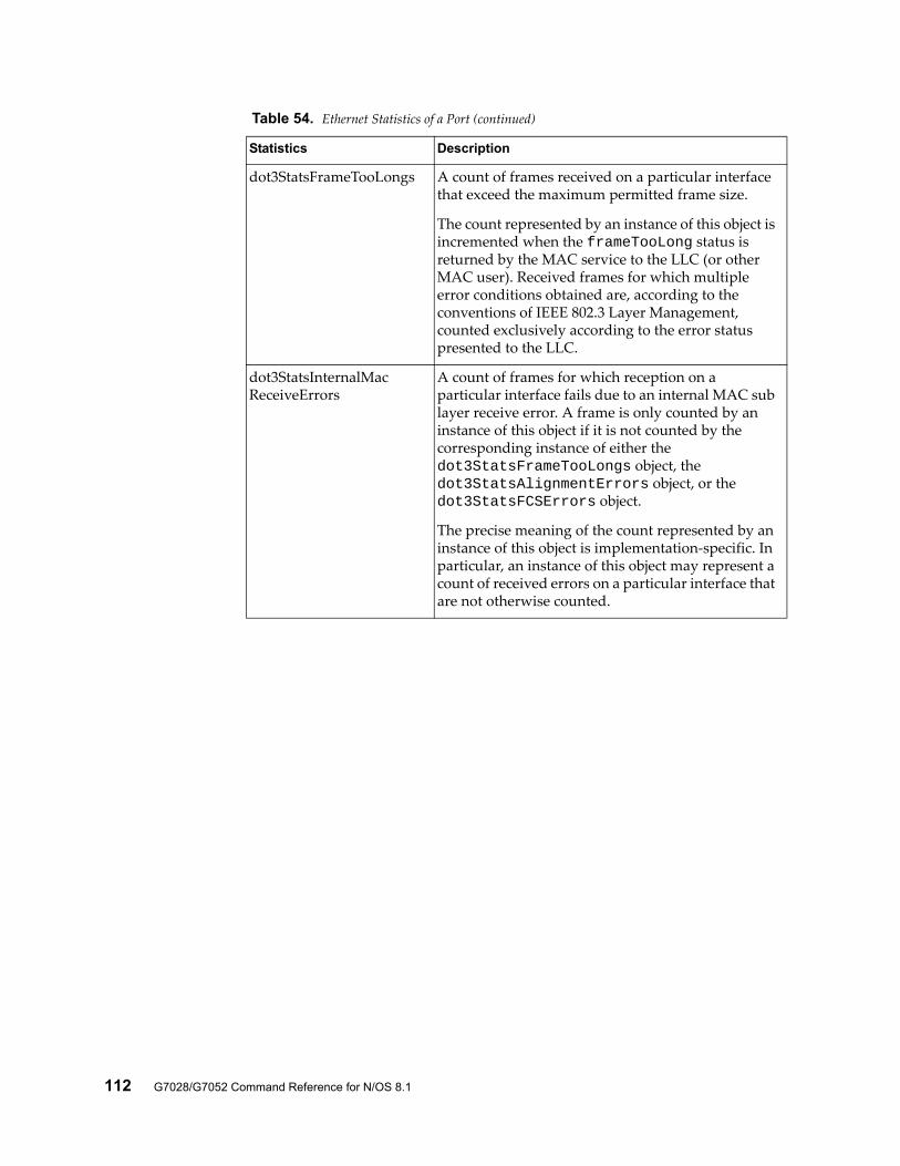
112 G7028/G7052 Command Reference for N/OS 8.1
dot3StatsFrameTooLongs A count of frames received on a particular interface that exceed the maximum permitted frame size.
The count represented by an instance of this object is incremented when the frameTooLong status is returned by the MAC service to the LLC (or other MAC user). Received frames for which multiple error conditions obtained are, according to the conventions of IEEE 802.3 Layer Management, counted exclusively according to the error status presented to the LLC.
dot3StatsInternalMacReceiveErrors
A count of frames for which reception on a particular interface fails due to an internal MAC sub layer receive error. A frame is only counted by an instance of this object if it is not counted by the corresponding instance of either the dot3StatsFrameTooLongs object, the dot3StatsAlignmentErrors object, or the dot3StatsFCSErrors object.
The precise meaning of the count represented by an instance of this object is implementation-specific. In particular, an instance of this object may represent a count of received errors on a particular interface that are not otherwise counted.
Table 54. Ethernet Statistics of a Port (continued)
Statistics Description
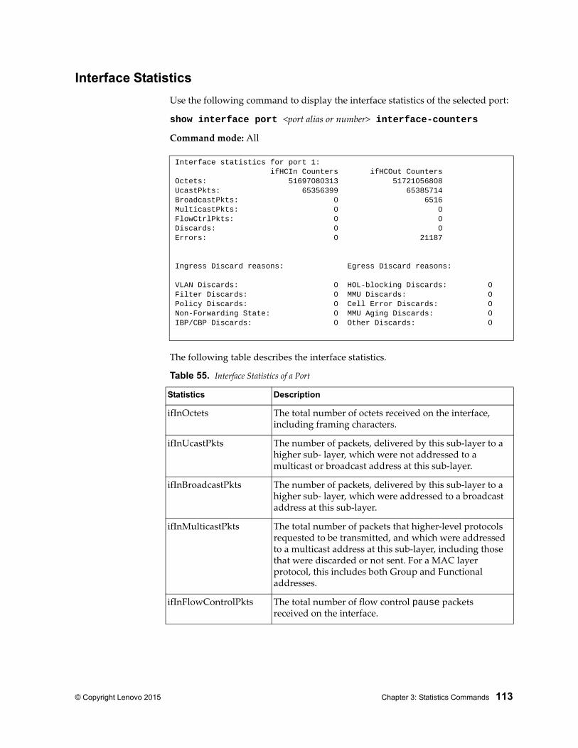
© Copyright Lenovo 2015 Chapter 3: Statistics Commands 113
Interface Statistics
Use the following command to display the interface statistics of the selected port:
show interface port <port alias or number> interface-counters
Command mode: All
The following table describes the interface statistics.
Interface statistics for port 1: ifHCIn Counters ifHCOut CountersOctets: 51697080313 51721056808UcastPkts: 65356399 65385714BroadcastPkts: 0 6516MulticastPkts: 0 0FlowCtrlPkts: 0 0Discards: 0 0Errors: 0 21187
Ingress Discard reasons: Egress Discard reasons:
VLAN Discards: 0 HOL-blocking Discards: 0Filter Discards: 0 MMU Discards: 0Policy Discards: 0 Cell Error Discards: 0Non-Forwarding State: 0 MMU Aging Discards: 0IBP/CBP Discards: 0 Other Discards: 0
Table 55. Interface Statistics of a Port
Statistics Description
ifInOctets The total number of octets received on the interface, including framing characters.
ifInUcastPkts The number of packets, delivered by this sub-layer to a higher sub- layer, which were not addressed to a multicast or broadcast address at this sub-layer.
ifInBroadcastPkts The number of packets, delivered by this sub-layer to a higher sub- layer, which were addressed to a broadcast address at this sub-layer.
ifInMulticastPkts The total number of packets that higher-level protocols requested to be transmitted, and which were addressed to a multicast address at this sub-layer, including those that were discarded or not sent. For a MAC layer protocol, this includes both Group and Functional addresses.
ifInFlowControlPkts The total number of flow control pause packets received on the interface.
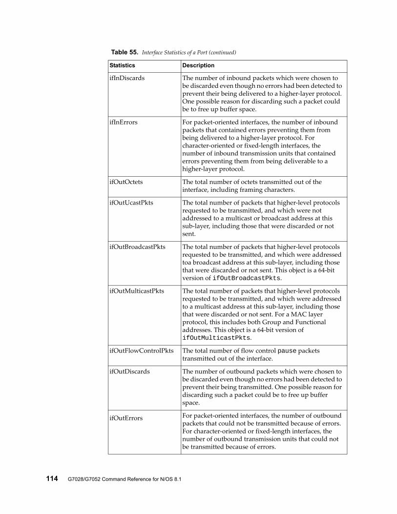
114 G7028/G7052 Command Reference for N/OS 8.1
ifInDiscards The number of inbound packets which were chosen to be discarded even though no errors had been detected to prevent their being delivered to a higher-layer protocol. One possible reason for discarding such a packet could be to free up buffer space.
ifInErrors For packet-oriented interfaces, the number of inbound packets that contained errors preventing them from being delivered to a higher-layer protocol. For character-oriented or fixed-length interfaces, the number of inbound transmission units that contained errors preventing them from being deliverable to a higher-layer protocol.
ifOutOctets The total number of octets transmitted out of the interface, including framing characters.
ifOutUcastPkts The total number of packets that higher-level protocols requested to be transmitted, and which were not addressed to a multicast or broadcast address at this sub-layer, including those that were discarded or not sent.
ifOutBroadcastPkts The total number of packets that higher-level protocols requested to be transmitted, and which were addressed toa broadcast address at this sub-layer, including those that were discarded or not sent. This object is a 64-bit version of ifOutBroadcastPkts.
ifOutMulticastPkts The total number of packets that higher-level protocols requested to be transmitted, and which were addressed to a multicast address at this sub-layer, including those that were discarded or not sent. For a MAC layer protocol, this includes both Group and Functional addresses. This object is a 64-bit version of ifOutMulticastPkts.
ifOutFlowControlPkts The total number of flow control pause packets transmitted out of the interface.
ifOutDiscards The number of outbound packets which were chosen to be discarded even though no errors had been detected to prevent their being transmitted. One possible reason for discarding such a packet could be to free up buffer space.
ifOutErrors For packet-oriented interfaces, the number of outbound packets that could not be transmitted because of errors. For character-oriented or fixed-length interfaces, the number of outbound transmission units that could not be transmitted because of errors.
Table 55. Interface Statistics of a Port (continued)
Statistics Description
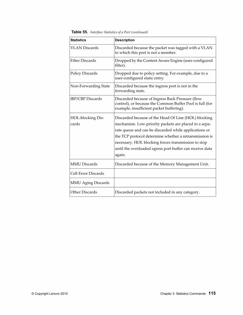
© Copyright Lenovo 2015 Chapter 3: Statistics Commands 115
VLAN Discards Discarded because the packet was tagged with a VLAN to which this port is not a member.
Filter Discards Dropped by the Content Aware Engine (user-configured filter).
Policy Discards Dropped due to policy setting. For example, due to a user-configured static entry.
Non-Forwarding State Discarded because the ingress port is not in the forwarding state.
IBP/CBP Discards Discarded because of Ingress Back Pressure (flow control), or because the Common Buffer Pool is full (for example, insufficient packet buffering).
HOL-blocking Dis-cards
Discarded because of the Head Of Line (HOL) blocking mechanism. Low-priority packets are placed in a sepa-rate queue and can be discarded while applications or the TCP protocol determine whether a retransmission is necessary. HOL blocking forces transmission to stop until the overloaded egress port buffer can receive data again.
MMU Discards Discarded because of the Memory Management Unit.
Cell Error Discards
MMU Aging Discards
Other Discards Discarded packets not included in any category.
Table 55. Interface Statistics of a Port (continued)
Statistics Description
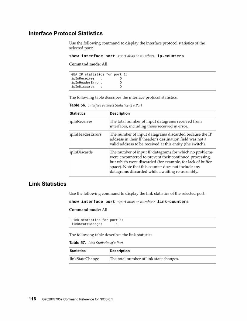
116 G7028/G7052 Command Reference for N/OS 8.1
Interface Protocol Statistics
Use the following command to display the interface protocol statistics of the selected port:
show interface port <port alias or number> ip-counters
Command mode: All
The following table describes the interface protocol statistics.
Link Statistics
Use the following command to display the link statistics of the selected port:
show interface port <port alias or number> link-counters
Command mode: All
The following table describes the link statistics.
GEA IP statistics for port 1:ipInReceives : 0ipInHeaderError: 0ipInDiscards : 0
Table 56. Interface Protocol Statistics of a Port
Statistics Description
ipInReceives The total number of input datagrams received from interfaces, including those received in error.
ipInHeaderErrors The number of input datagrams discarded because the IP address in their IP header's destination field was not a valid address to be received at this entity (the switch).
ipInDiscards The number of input IP datagrams for which no problems were encountered to prevent their continued processing, but which were discarded (for example, for lack of buffer space). Note that this counter does not include any datagrams discarded while awaiting re-assembly.
Link statistics for port 1:linkStateChange: 1
Table 57. Link Statistics of a Port
Statistics Description
linkStateChange The total number of link state changes.
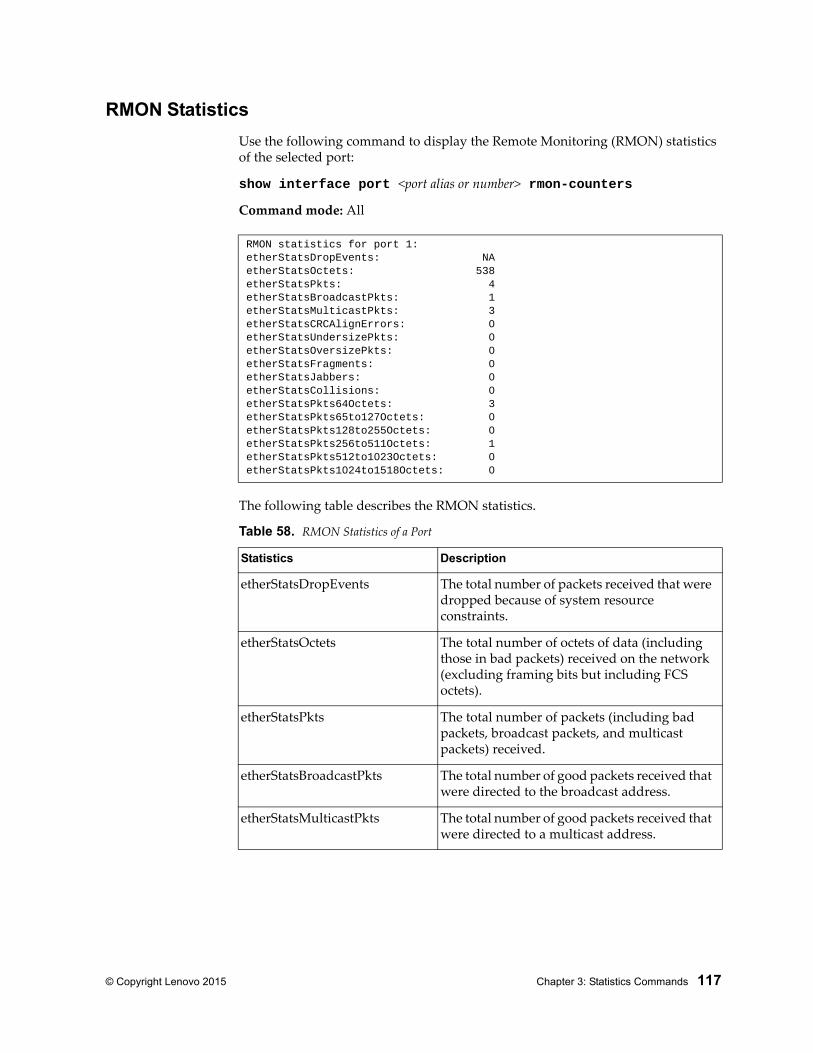
© Copyright Lenovo 2015 Chapter 3: Statistics Commands 117
RMON Statistics
Use the following command to display the Remote Monitoring (RMON) statistics of the selected port:
show interface port <port alias or number> rmon-counters
Command mode: All
The following table describes the RMON statistics.
RMON statistics for port 1:etherStatsDropEvents: NAetherStatsOctets: 538etherStatsPkts: 4etherStatsBroadcastPkts: 1etherStatsMulticastPkts: 3etherStatsCRCAlignErrors: 0etherStatsUndersizePkts: 0etherStatsOversizePkts: 0etherStatsFragments: 0etherStatsJabbers: 0etherStatsCollisions: 0etherStatsPkts64Octets: 3etherStatsPkts65to127Octets: 0etherStatsPkts128to255Octets: 0etherStatsPkts256to511Octets: 1etherStatsPkts512to1023Octets: 0etherStatsPkts1024to1518Octets: 0
Table 58. RMON Statistics of a Port
Statistics Description
etherStatsDropEvents The total number of packets received that were dropped because of system resource constraints.
etherStatsOctets The total number of octets of data (including those in bad packets) received on the network (excluding framing bits but including FCS octets).
etherStatsPkts The total number of packets (including bad packets, broadcast packets, and multicast packets) received.
etherStatsBroadcastPkts The total number of good packets received that were directed to the broadcast address.
etherStatsMulticastPkts The total number of good packets received that were directed to a multicast address.
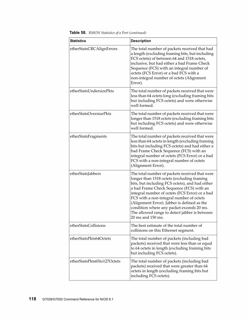
118 G7028/G7052 Command Reference for N/OS 8.1
etherStatsCRCAlignErrors The total number of packets received that had a length (excluding framing bits, but including FCS octets) of between 64 and 1518 octets, inclusive, but had either a bad Frame Check Sequence (FCS) with an integral number of octets (FCS Error) or a bad FCS with a non-integral number of octets (Alignment Error).
etherStatsUndersizePkts The total number of packets received that were less than 64 octets long (excluding framing bits but including FCS octets) and were otherwise well formed.
etherStatsOversizePkts The total number of packets received that were longer than 1518 octets (excluding framing bits but including FCS octets) and were otherwise well formed.
etherStatsFragments The total number of packets received that were less than 64 octets in length (excluding framing bits but including FCS octets) and had either a bad Frame Check Sequence (FCS) with an integral number of octets (FCS Error) or a bad FCS with a non-integral number of octets (Alignment Error).
etherStatsJabbers The total number of packets received that were longer than 1518 octets (excluding framing bits, but including FCS octets), and had either a bad Frame Check Sequence (FCS) with an integral number of octets (FCS Error) or a bad FCS with a non-integral number of octets (Alignment Error). Jabber is defined as the condition where any packet exceeds 20 ms. The allowed range to detect jabber is between 20 ms and 150 ms.
etherStatsCollisions The best estimate of the total number of collisions on this Ethernet segment.
etherStatsPkts64Octets The total number of packets (including bad packets) received that were less than or equal to 64 octets in length (excluding framing bits but including FCS octets).
etherStatsPkts65to127Octets The total number of packets (including bad packets) received that were greater than 64 octets in length (excluding framing bits but including FCS octets).
Table 58. RMON Statistics of a Port (continued)
Statistics Description
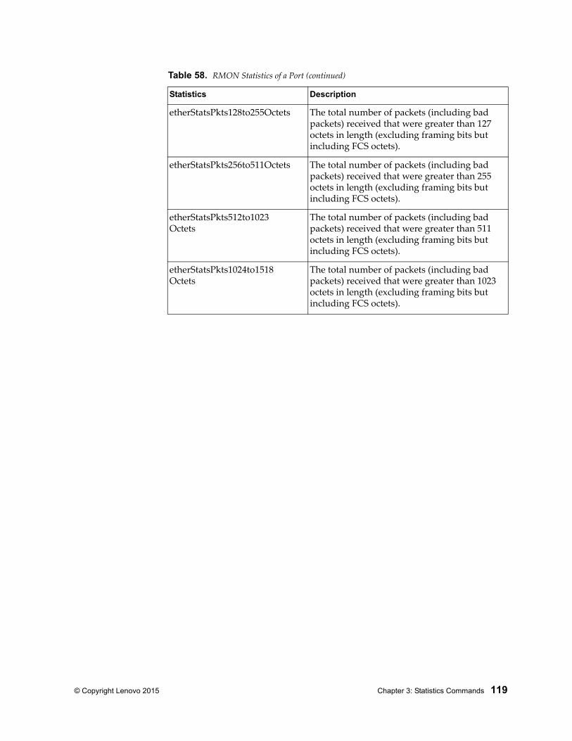
© Copyright Lenovo 2015 Chapter 3: Statistics Commands 119
etherStatsPkts128to255Octets The total number of packets (including bad packets) received that were greater than 127 octets in length (excluding framing bits but including FCS octets).
etherStatsPkts256to511Octets The total number of packets (including bad packets) received that were greater than 255 octets in length (excluding framing bits but including FCS octets).
etherStatsPkts512to1023Octets
The total number of packets (including bad packets) received that were greater than 511 octets in length (excluding framing bits but including FCS octets).
etherStatsPkts1024to1518Octets
The total number of packets (including bad packets) received that were greater than 1023 octets in length (excluding framing bits but including FCS octets).
Table 58. RMON Statistics of a Port (continued)
Statistics Description
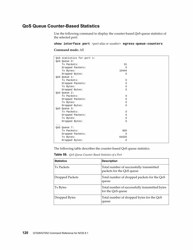
120 G7028/G7052 Command Reference for N/OS 8.1
QoS Queue Counter-Based Statistics
Use the following command to display the counter-based QoS queue statistics of the selected port:
show interface port <port alias or number> egress-queue-counters
Command mode: All
The following table describes the counter-based QoS queue statistics.
QoS statistics for port 1:QoS Queue 0: Tx Packets: 31 Dropped Packets: 0 Tx Bytes: 10444 Dropped Bytes: 0QoS Queue 1: Tx Packets: 0 Dropped Packets: 0 Tx Bytes: 0 Dropped Bytes: 0QoS Queue 2: Tx Packets: 0 Dropped Packets: 0 Tx Bytes: 0 Dropped Bytes: 0QoS Queue 3: Tx Packets: 0 Dropped Packets: 0 Tx Bytes: 0 Dropped Bytes: 0...QoS Queue 7: Tx Packets: 900 Dropped Packets: 0 Tx Bytes: 64320 Dropped Bytes: 0
Table 59. QoS Queue Counter-Based Statistics of a Port
Statistics Description
Tx Packets Total number of successfully transmitted packets for the QoS queue
Dropped Packets Total number of dropped packets for the QoS queue
Tx Bytes Total number of successfully transmitted bytes for the QoS queue
Dropped Bytes Total number of dropped bytes for the QoS queue
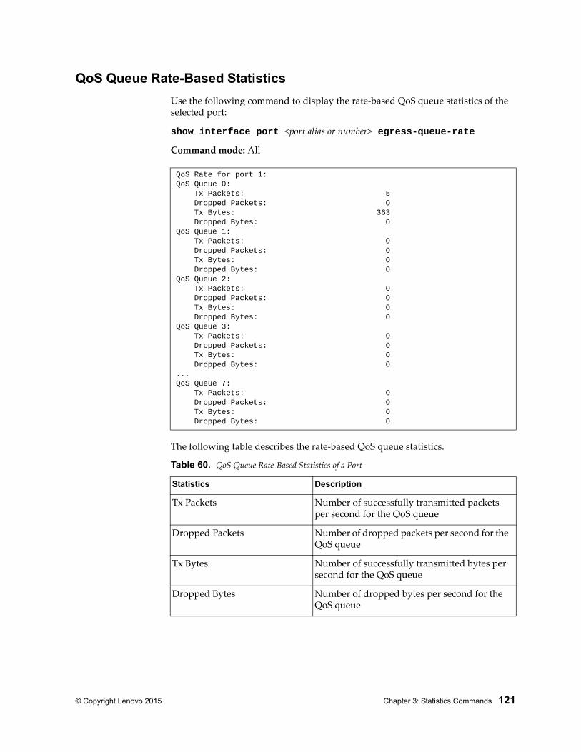
© Copyright Lenovo 2015 Chapter 3: Statistics Commands 121
QoS Queue Rate-Based Statistics
Use the following command to display the rate-based QoS queue statistics of the selected port:
show interface port <port alias or number> egress-queue-rate
Command mode: All
The following table describes the rate-based QoS queue statistics.
QoS Rate for port 1:QoS Queue 0: Tx Packets: 5 Dropped Packets: 0 Tx Bytes: 363 Dropped Bytes: 0QoS Queue 1: Tx Packets: 0 Dropped Packets: 0 Tx Bytes: 0 Dropped Bytes: 0QoS Queue 2: Tx Packets: 0 Dropped Packets: 0 Tx Bytes: 0 Dropped Bytes: 0QoS Queue 3: Tx Packets: 0 Dropped Packets: 0 Tx Bytes: 0 Dropped Bytes: 0...QoS Queue 7: Tx Packets: 0 Dropped Packets: 0 Tx Bytes: 0 Dropped Bytes: 0
Table 60. QoS Queue Rate-Based Statistics of a Port
Statistics Description
Tx Packets Number of successfully transmitted packets per second for the QoS queue
Dropped Packets Number of dropped packets per second for the QoS queue
Tx Bytes Number of successfully transmitted bytes per second for the QoS queue
Dropped Bytes Number of dropped bytes per second for the QoS queue
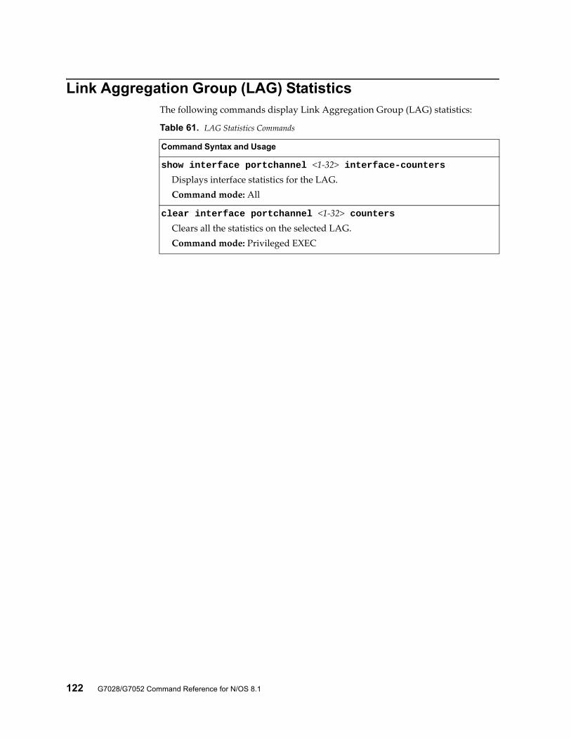
122 G7028/G7052 Command Reference for N/OS 8.1
Link Aggregation Group (LAG) StatisticsThe following commands display Link Aggregation Group (LAG) statistics:
Table 61. LAG Statistics Commands
Command Syntax and Usage
show interface portchannel <1-32> interface-countersDisplays interface statistics for the LAG.Command mode: All
clear interface portchannel <1-32> countersClears all the statistics on the selected LAG.Command mode: Privileged EXEC
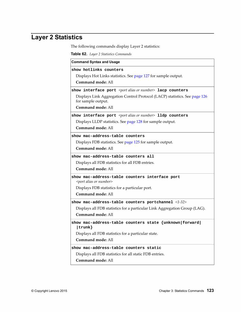
© Copyright Lenovo 2015 Chapter 3: Statistics Commands 123
Layer 2 StatisticsThe following commands display Layer 2 statistics:
Table 62. Layer 2 Statistics Commands
Command Syntax and Usage
show hotlinks counters
Displays Hot Links statistics. See page 127 for sample output.Command mode: All
show interface port <port alias or number> lacp countersDisplays Link Aggregation Control Protocol (LACP) statistics. See page 126 for sample output.Command mode: All
show interface port <port alias or number> lldp countersDisplays LLDP statistics. See page 128 for sample output.Command mode: All
show mac-address-table counters
Displays FDB statistics. See page 125 for sample output.Command mode: All
show mac-address-table counters all
Displays all FDB statistics for all FDB entries.Command mode: All
show mac-address-table counters interface port <port alias or number>
Displays FDB statistics for a particular port.Command mode: All
show mac-address-table counters portchannel <1-32>Displays all FDB statistics for a particular Link Aggregation Group (LAG).Command mode: All
show mac-address-table counters state {unknown|forward| |trunk}
Displays all FDB statistics for a particular state.Command mode: All
show mac-address-table counters static
Displays all FDB statistics for all static FDB entries.Command mode: All
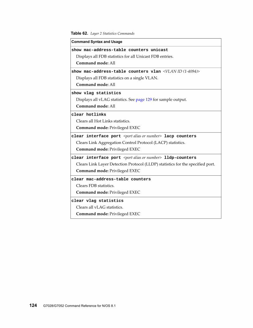
124 G7028/G7052 Command Reference for N/OS 8.1
show mac-address-table counters unicast
Displays all FDB statistics for all Unicast FDB entries.Command mode: All
show mac-address-table counters vlan <VLAN ID (1-4094)>Displays all FDB statistics on a single VLAN.Command mode: All
show vlag statistics
Displays all vLAG statistics. See page 129 for sample output.Command mode: All
clear hotlinks
Clears all Hot Links statistics.Command mode: Privileged EXEC
clear interface port <port alias or number> lacp countersClears Link Aggregation Control Protocol (LACP) statistics.Command mode: Privileged EXEC
clear interface port <port alias or number> lldp-countersClears Link Layer Detection Protocol (LLDP) statistics for the specified port.Command mode: Privileged EXEC
clear mac-address-table counters
Clears FDB statistics.Command mode: Privileged EXEC
clear vlag statistics
Clears all vLAG statistics.Command mode: Privileged EXEC
Table 62. Layer 2 Statistics Commands
Command Syntax and Usage
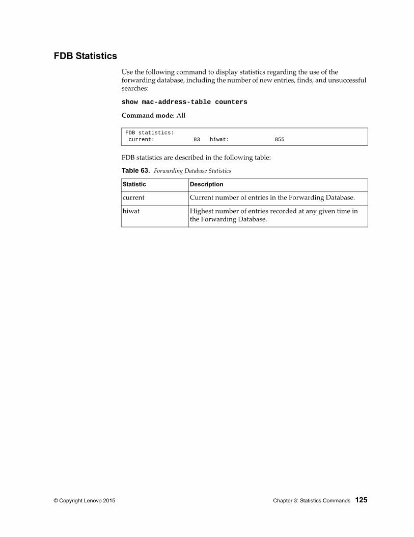
© Copyright Lenovo 2015 Chapter 3: Statistics Commands 125
FDB Statistics
Use the following command to display statistics regarding the use of the forwarding database, including the number of new entries, finds, and unsuccessful searches:
show mac-address-table counters
Command mode: All
FDB statistics are described in the following table:
FDB statistics: current: 83 hiwat: 855
Table 63. Forwarding Database Statistics
Statistic Description
current Current number of entries in the Forwarding Database.
hiwat Highest number of entries recorded at any given time in the Forwarding Database.
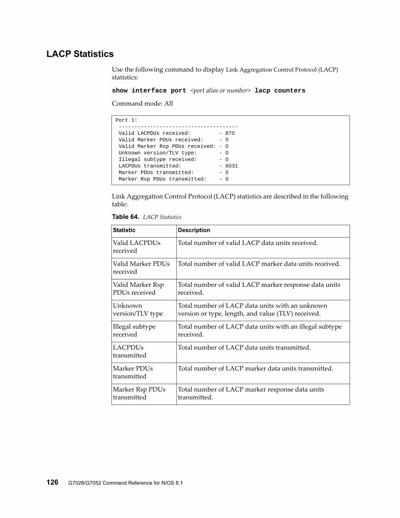
126 G7028/G7052 Command Reference for N/OS 8.1
LACP Statistics
Use the following command to display Link Aggregation Control Protocol (LACP) statistics:
show interface port <port alias or number> lacp counters
Command mode: All
Link Aggregation Control Protocol (LACP) statistics are described in the following table:
Port 1: -------------------------------------- Valid LACPDUs received: - 870 Valid Marker PDUs received: - 0 Valid Marker Rsp PDUs received: - 0 Unknown version/TLV type: - 0 Illegal subtype received: - 0 LACPDUs transmitted: - 6031 Marker PDUs transmitted: - 0 Marker Rsp PDUs transmitted: - 0
Table 64. LACP Statistics
Statistic Description
Valid LACPDUs received
Total number of valid LACP data units received.
Valid Marker PDUs received
Total number of valid LACP marker data units received.
Valid Marker Rsp PDUs received
Total number of valid LACP marker response data units received.
Unknown version/TLV type
Total number of LACP data units with an unknown version or type, length, and value (TLV) received.
Illegal subtype received
Total number of LACP data units with an illegal subtype received.
LACPDUs transmitted
Total number of LACP data units transmitted.
Marker PDUs transmitted
Total number of LACP marker data units transmitted.
Marker Rsp PDUs transmitted
Total number of LACP marker response data units transmitted.
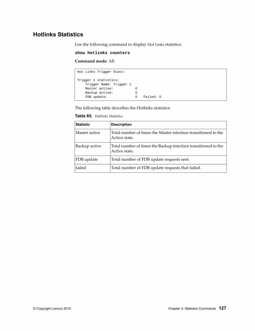
© Copyright Lenovo 2015 Chapter 3: Statistics Commands 127
Hotlinks Statistics
Use the following command to display Hot Links statistics:
show hotlinks counters
Command mode: All
The following table describes the Hotlinks statistics:
Hot Links Trigger Stats:
Trigger 1 statistics: Trigger Name: Trigger 1 Master active: 0 Backup active: 0 FDB update: 0 failed: 0
Table 65. Hotlinks Statistics
Statistic Description
Master active Total number of times the Master interface transitioned to the Active state.
Backup active Total number of times the Backup interface transitioned to the Active state.
FDB update Total number of FDB update requests sent.
failed Total number of FDB update requests that failed.
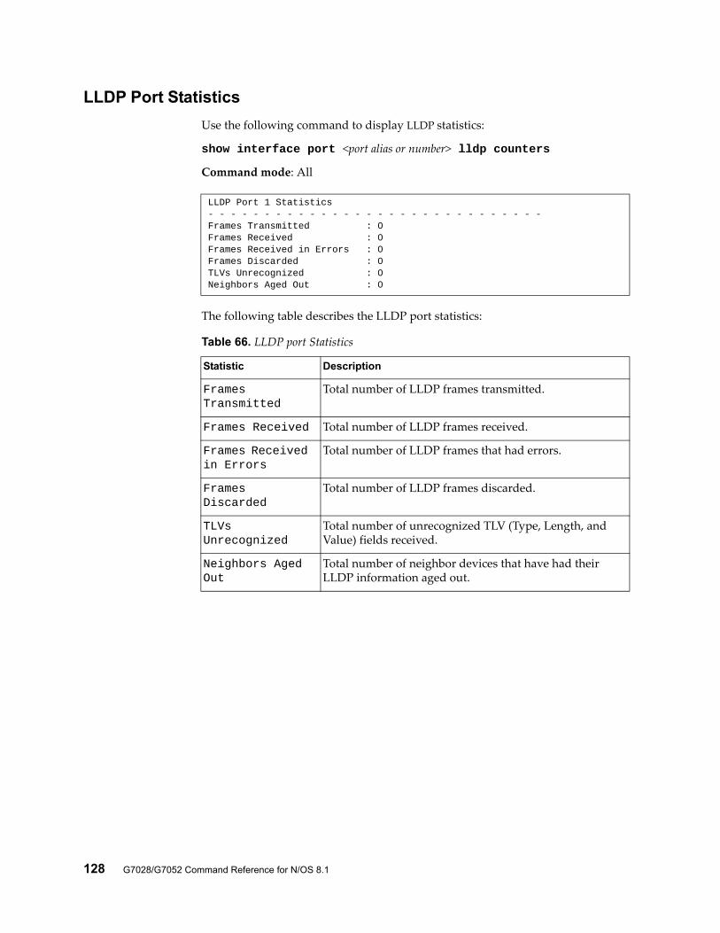
128 G7028/G7052 Command Reference for N/OS 8.1
LLDP Port Statistics
Use the following command to display LLDP statistics:
show interface port <port alias or number> lldp counters
Command mode: All
The following table describes the LLDP port statistics:
LLDP Port 1 Statistics- - - - - - - - - - - - - - - - - - - - - - - - - - - - - -Frames Transmitted : 0Frames Received : 0Frames Received in Errors : 0Frames Discarded : 0TLVs Unrecognized : 0Neighbors Aged Out : 0
Table 66. LLDP port Statistics
Statistic Description
Frames Transmitted
Total number of LLDP frames transmitted.
Frames Received Total number of LLDP frames received.
Frames Received in Errors
Total number of LLDP frames that had errors.
Frames Discarded
Total number of LLDP frames discarded.
TLVs Unrecognized
Total number of unrecognized TLV (Type, Length, and Value) fields received.
Neighbors Aged Out
Total number of neighbor devices that have had their LLDP information aged out.
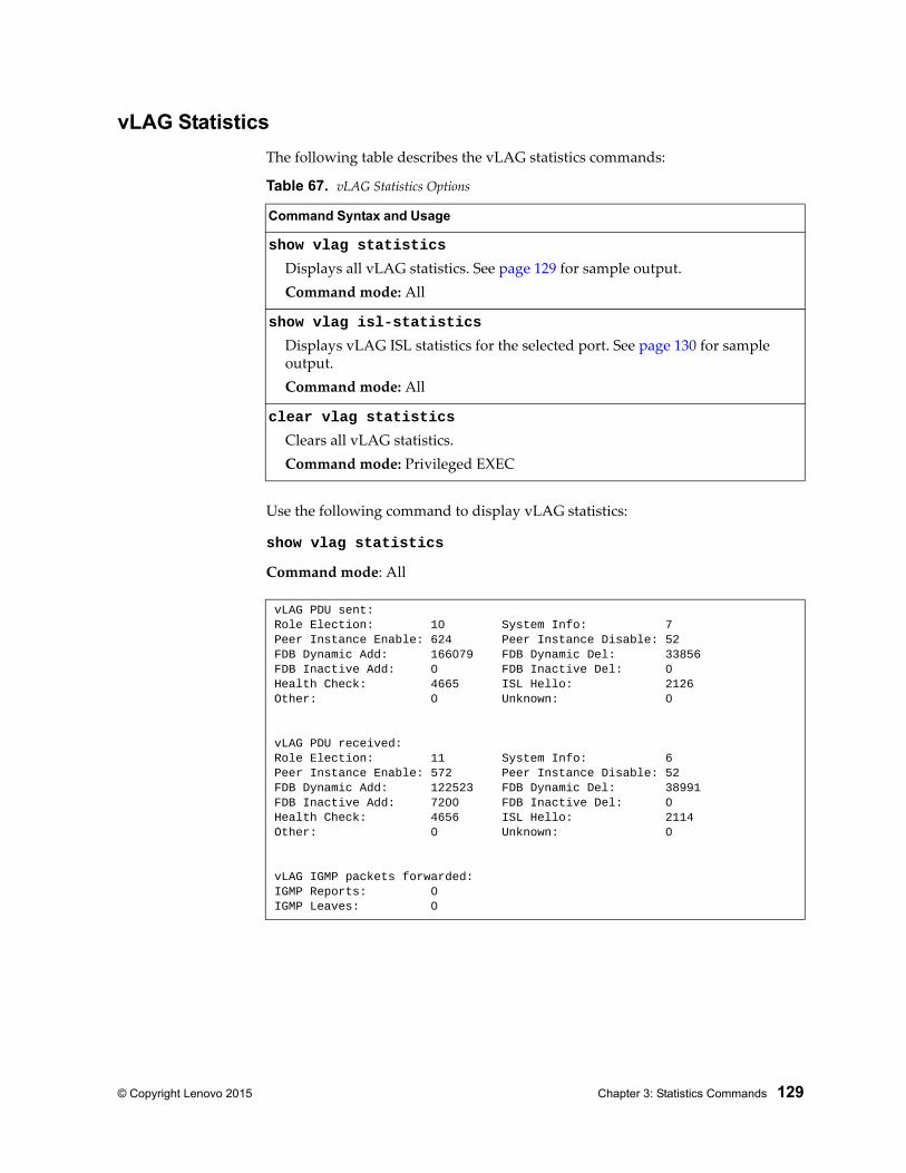
© Copyright Lenovo 2015 Chapter 3: Statistics Commands 129
vLAG Statistics
The following table describes the vLAG statistics commands:
Use the following command to display vLAG statistics:
show vlag statistics
Command mode: All
Table 67. vLAG Statistics Options
Command Syntax and Usage
show vlag statistics
Displays all vLAG statistics. See page 129 for sample output.Command mode: All
show vlag isl-statistics
Displays vLAG ISL statistics for the selected port. See page 130 for sample output.Command mode: All
clear vlag statistics
Clears all vLAG statistics.Command mode: Privileged EXEC
vLAG PDU sent:Role Election: 10 System Info: 7Peer Instance Enable: 624 Peer Instance Disable: 52FDB Dynamic Add: 166079 FDB Dynamic Del: 33856FDB Inactive Add: 0 FDB Inactive Del: 0Health Check: 4665 ISL Hello: 2126Other: 0 Unknown: 0
vLAG PDU received:Role Election: 11 System Info: 6Peer Instance Enable: 572 Peer Instance Disable: 52FDB Dynamic Add: 122523 FDB Dynamic Del: 38991FDB Inactive Add: 7200 FDB Inactive Del: 0Health Check: 4656 ISL Hello: 2114Other: 0 Unknown: 0
vLAG IGMP packets forwarded:IGMP Reports: 0IGMP Leaves: 0
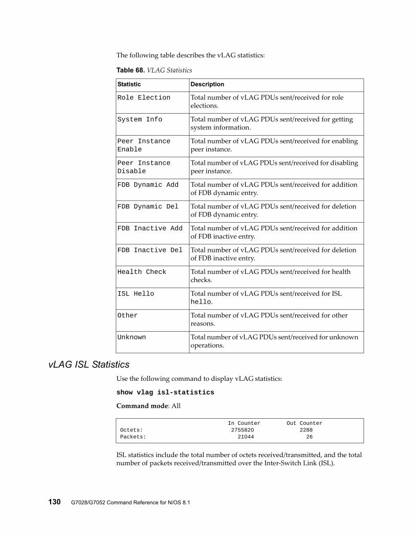
130 G7028/G7052 Command Reference for N/OS 8.1
The following table describes the vLAG statistics:
vLAG ISL StatisticsUse the following command to display vLAG statistics:
show vlag isl-statistics
Command mode: All
ISL statistics include the total number of octets received/transmitted, and the total number of packets received/transmitted over the Inter-Switch Link (ISL).
Table 68. VLAG Statistics
Statistic Description
Role Election Total number of vLAG PDUs sent/received for role elections.
System Info Total number of vLAG PDUs sent/received for getting system information.
Peer Instance Enable
Total number of vLAG PDUs sent/received for enabling peer instance.
Peer Instance Disable
Total number of vLAG PDUs sent/received for disabling peer instance.
FDB Dynamic Add Total number of vLAG PDUs sent/received for addition of FDB dynamic entry.
FDB Dynamic Del Total number of vLAG PDUs sent/received for deletion of FDB dynamic entry.
FDB Inactive Add Total number of vLAG PDUs sent/received for addition of FDB inactive entry.
FDB Inactive Del Total number of vLAG PDUs sent/received for deletion of FDB inactive entry.
Health Check Total number of vLAG PDUs sent/received for health checks.
ISL Hello Total number of vLAG PDUs sent/received for ISL hello.
Other Total number of vLAG PDUs sent/received for other reasons.
Unknown Total number of vLAG PDUs sent/received for unknown operations.
In Counter Out CounterOctets: 2755820 2288Packets: 21044 26
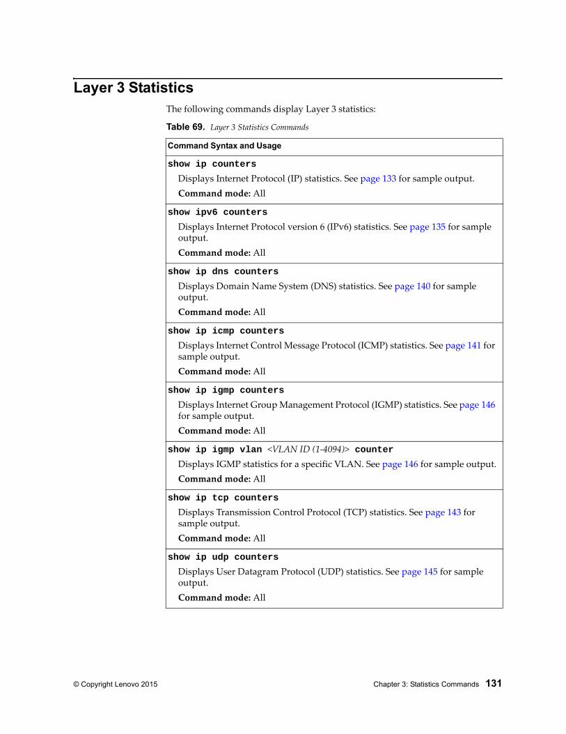
© Copyright Lenovo 2015 Chapter 3: Statistics Commands 131
Layer 3 StatisticsThe following commands display Layer 3 statistics:
Table 69. Layer 3 Statistics Commands
Command Syntax and Usage
show ip counters
Displays Internet Protocol (IP) statistics. See page 133 for sample output.Command mode: All
show ipv6 counters
Displays Internet Protocol version 6 (IPv6) statistics. See page 135 for sample output.Command mode: All
show ip dns counters
Displays Domain Name System (DNS) statistics. See page 140 for sample output.Command mode: All
show ip icmp counters
Displays Internet Control Message Protocol (ICMP) statistics. See page 141 for sample output.Command mode: All
show ip igmp counters
Displays Internet Group Management Protocol (IGMP) statistics. See page 146 for sample output.Command mode: All
show ip igmp vlan <VLAN ID (1-4094)> counterDisplays IGMP statistics for a specific VLAN. See page 146 for sample output.Command mode: All
show ip tcp counters
Displays Transmission Control Protocol (TCP) statistics. See page 143 for sample output.Command mode: All
show ip udp counters
Displays User Datagram Protocol (UDP) statistics. See page 145 for sample output.Command mode: All
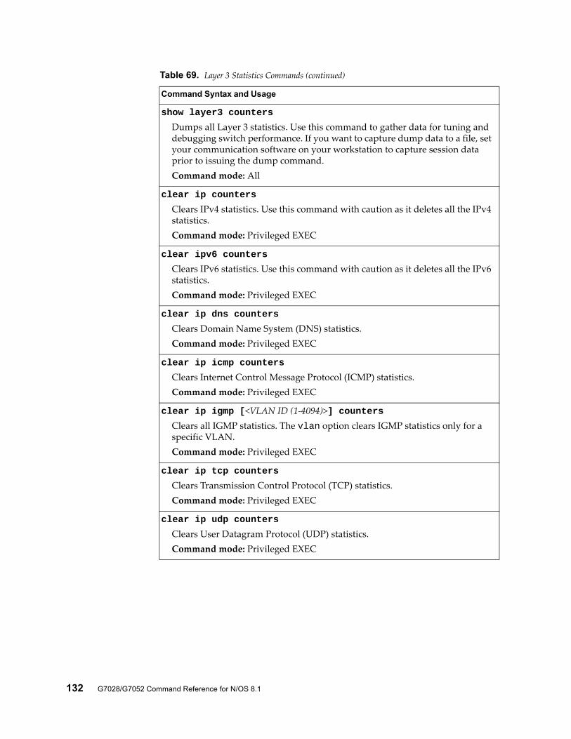
132 G7028/G7052 Command Reference for N/OS 8.1
show layer3 counters
Dumps all Layer 3 statistics. Use this command to gather data for tuning and debugging switch performance. If you want to capture dump data to a file, set your communication software on your workstation to capture session data prior to issuing the dump command.Command mode: All
clear ip counters
Clears IPv4 statistics. Use this command with caution as it deletes all the IPv4 statistics.Command mode: Privileged EXEC
clear ipv6 counters
Clears IPv6 statistics. Use this command with caution as it deletes all the IPv6 statistics.Command mode: Privileged EXEC
clear ip dns counters
Clears Domain Name System (DNS) statistics.Command mode: Privileged EXEC
clear ip icmp counters
Clears Internet Control Message Protocol (ICMP) statistics.Command mode: Privileged EXEC
clear ip igmp [<VLAN ID (1-4094)>] countersClears all IGMP statistics. The vlan option clears IGMP statistics only for a specific VLAN.Command mode: Privileged EXEC
clear ip tcp counters
Clears Transmission Control Protocol (TCP) statistics.Command mode: Privileged EXEC
clear ip udp counters
Clears User Datagram Protocol (UDP) statistics.Command mode: Privileged EXEC
Table 69. Layer 3 Statistics Commands (continued)
Command Syntax and Usage
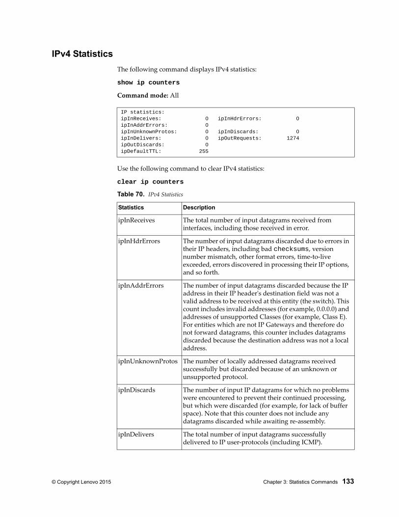
© Copyright Lenovo 2015 Chapter 3: Statistics Commands 133
IPv4 Statistics
The following command displays IPv4 statistics:
show ip counters
Command mode: All
Use the following command to clear IPv4 statistics:
clear ip counters
IP statistics:ipInReceives: 0 ipInHdrErrors: 0ipInAddrErrors: 0ipInUnknownProtos: 0 ipInDiscards: 0ipInDelivers: 0 ipOutRequests: 1274ipOutDiscards: 0ipDefaultTTL: 255
Table 70. IPv4 Statistics
Statistics Description
ipInReceives The total number of input datagrams received from interfaces, including those received in error.
ipInHdrErrors The number of input datagrams discarded due to errors in their IP headers, including bad checksums, version number mismatch, other format errors, time-to-live exceeded, errors discovered in processing their IP options, and so forth.
ipInAddrErrors The number of input datagrams discarded because the IP address in their IP header's destination field was not a valid address to be received at this entity (the switch). This count includes invalid addresses (for example, 0.0.0.0) and addresses of unsupported Classes (for example, Class E). For entities which are not IP Gateways and therefore do not forward datagrams, this counter includes datagrams discarded because the destination address was not a local address.
ipInUnknownProtos The number of locally addressed datagrams received successfully but discarded because of an unknown or unsupported protocol.
ipInDiscards The number of input IP datagrams for which no problems were encountered to prevent their continued processing, but which were discarded (for example, for lack of buffer space). Note that this counter does not include any datagrams discarded while awaiting re-assembly.
ipInDelivers The total number of input datagrams successfully delivered to IP user-protocols (including ICMP).
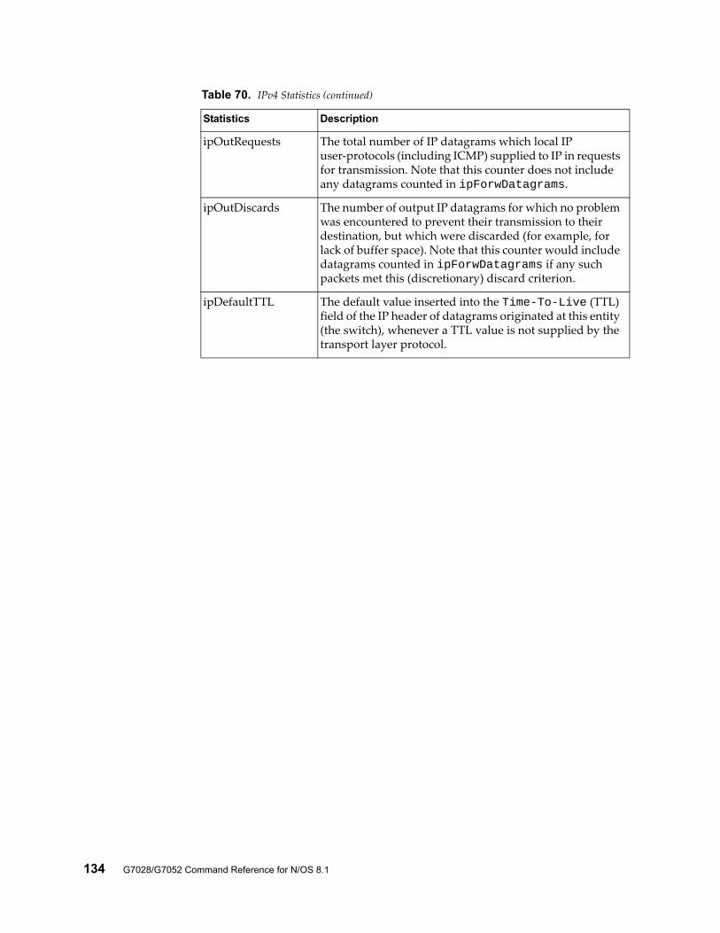
134 G7028/G7052 Command Reference for N/OS 8.1
ipOutRequests The total number of IP datagrams which local IP user-protocols (including ICMP) supplied to IP in requests for transmission. Note that this counter does not include any datagrams counted in ipForwDatagrams.
ipOutDiscards The number of output IP datagrams for which no problem was encountered to prevent their transmission to their destination, but which were discarded (for example, for lack of buffer space). Note that this counter would include datagrams counted in ipForwDatagrams if any such packets met this (discretionary) discard criterion.
ipDefaultTTL The default value inserted into the Time-To-Live (TTL) field of the IP header of datagrams originated at this entity (the switch), whenever a TTL value is not supplied by the transport layer protocol.
Table 70. IPv4 Statistics (continued)
Statistics Description
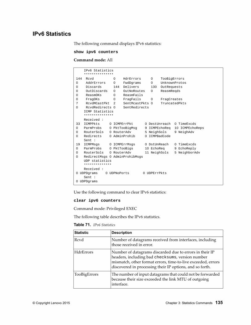
© Copyright Lenovo 2015 Chapter 3: Statistics Commands 135
IPv6 Statistics
The following command displays IPv6 statistics:
show ipv6 counters
Command mode: All
Use the following command to clear IPv6 statistics:
clear ipv6 counters
Command mode: Privileged EXEC
The following table describes the IPv6 statistics.
IPv6 Statistics ***************144 Rcvd 0 HdrErrors 0 TooBigErrors0 AddrErrors 0 FwdDgrams 0 UnknownProtos0 Discards 144 Delivers 130 OutRequests0 OutDiscards 0 OutNoRoutes 0 ReasmReqds0 ReasmOKs 0 ReasmFails0 FragOKs 0 FragFails 0 FragCreates7 RcvdMCastPkt 2 SentMcastPkts 0 TruncatedPkts0 RcvdRedirects 0 SentRedirects ICMP Statistics *************** Received :33 ICMPPkts 0 ICMPErrPkt 0 DestUnreach 0 TimeExcds0 ParmProbs 0 PktTooBigMsg 9 ICMPEchoReq 10 ICMPEchoReps0 RouterSols 0 RouterAdv 5 NeighSols 9 NeighAdv0 Redirects 0 AdminProhib 0 ICMPBadCode Sent :19 ICMPMsgs 0 ICMPErrMsgs 0 DstUnReach 0 TimeExcds0 ParmProbs 0 PktTooBigs 10 EchoReq 9 EchoReply0 RouterSols 0 RouterAdv 11 NeighSols 5 NeighborAdv0 RedirectMsgs 0 AdminProhibMsgs UDP statistics ************** Received :0 UDPDgrams 0 UDPNoPorts 0 UDPErrPkts Sent :0 UDPDgrams
Table 71. IPv6 Statistics
Statistic Description
Rcvd Number of datagrams received from interfaces, including those received in error.
HdrErrors Number of datagrams discarded due to errors in their IP headers, including bad checksums, version number mismatch, other format errors, time-to-live exceeded, errors discovered in processing their IP options, and so forth.
TooBigErrors The number of input datagrams that could not be forwarded because their size exceeded the link MTU of outgoing interface.
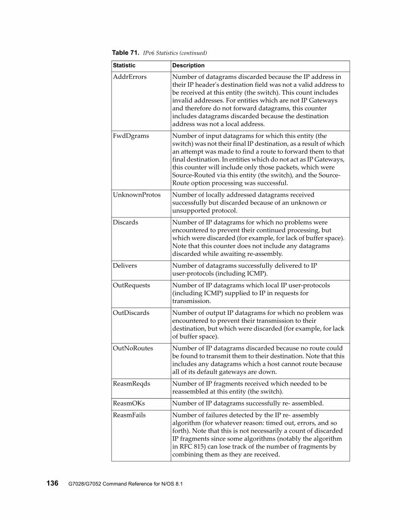
136 G7028/G7052 Command Reference for N/OS 8.1
AddrErrors Number of datagrams discarded because the IP address in their IP header's destination field was not a valid address to be received at this entity (the switch). This count includes invalid addresses. For entities which are not IP Gateways and therefore do not forward datagrams, this counter includes datagrams discarded because the destination address was not a local address.
FwdDgrams Number of input datagrams for which this entity (the switch) was not their final IP destination, as a result of which an attempt was made to find a route to forward them to that final destination. In entities which do not act as IP Gateways, this counter will include only those packets, which were Source-Routed via this entity (the switch), and the Source- Route option processing was successful.
UnknownProtos Number of locally addressed datagrams received successfully but discarded because of an unknown or unsupported protocol.
Discards Number of IP datagrams for which no problems were encountered to prevent their continued processing, but which were discarded (for example, for lack of buffer space). Note that this counter does not include any datagrams discarded while awaiting re-assembly.
Delivers Number of datagrams successfully delivered to IP user-protocols (including ICMP).
OutRequests Number of IP datagrams which local IP user-protocols (including ICMP) supplied to IP in requests for transmission.
OutDiscards Number of output IP datagrams for which no problem was encountered to prevent their transmission to their destination, but which were discarded (for example, for lack of buffer space).
OutNoRoutes Number of IP datagrams discarded because no route could be found to transmit them to their destination. Note that this includes any datagrams which a host cannot route because all of its default gateways are down.
ReasmReqds Number of IP fragments received which needed to be reassembled at this entity (the switch).
ReasmOKs Number of IP datagrams successfully re- assembled.
ReasmFails Number of failures detected by the IP re- assembly algorithm (for whatever reason: timed out, errors, and so forth). Note that this is not necessarily a count of discarded IP fragments since some algorithms (notably the algorithm in RFC 815) can lose track of the number of fragments by combining them as they are received.
Table 71. IPv6 Statistics (continued)
Statistic Description
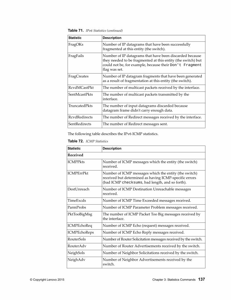
© Copyright Lenovo 2015 Chapter 3: Statistics Commands 137
The following table describes the IPv6 ICMP statistics.
FragOKs Number of IP datagrams that have been successfully fragmented at this entity (the switch).
FragFails Number of IP datagrams that have been discarded because they needed to be fragmented at this entity (the switch) but could not be, for example, because their Don't Fragment flag was set.
FragCreates Number of IP datagram fragments that have been generated as a result of fragmentation at this entity (the switch).
RcvdMCastPkt The number of multicast packets received by the interface.
SentMcastPkts The number of multicast packets transmitted by the interface.
TruncatedPkts The number of input datagrams discarded because datagram frame didn't carry enough data.
RcvdRedirects The number of Redirect messages received by the interface.
SentRedirects The number of Redirect messages sent.
Table 72. ICMP Statistics
Statistic Description
Received
ICMPPkts Number of ICMP messages which the entity (the switch) received.
ICMPErrPkt Number of ICMP messages which the entity (the switch) received but determined as having ICMP-specific errors (bad ICMP checksums, bad length, and so forth).
DestUnreach Number of ICMP Destination Unreachable messages received.
TimeExcds Number of ICMP Time Exceeded messages received.
ParmProbs Number of ICMP Parameter Problem messages received.
PktTooBigMsg The number of ICMP Packet Too Big messages received by the interface.
ICMPEchoReq Number of ICMP Echo (request) messages received.
ICMPEchoReps Number of ICMP Echo Reply messages received.
RouterSols Number of Router Solicitation messages received by the switch.
RouterAdv Number of Router Advertisements received by the switch.
NeighSols Number of Neighbor Solicitations received by the switch.
NeighAdv Number of Neighbor Advertisements received by the switch.
Table 71. IPv6 Statistics (continued)
Statistic Description
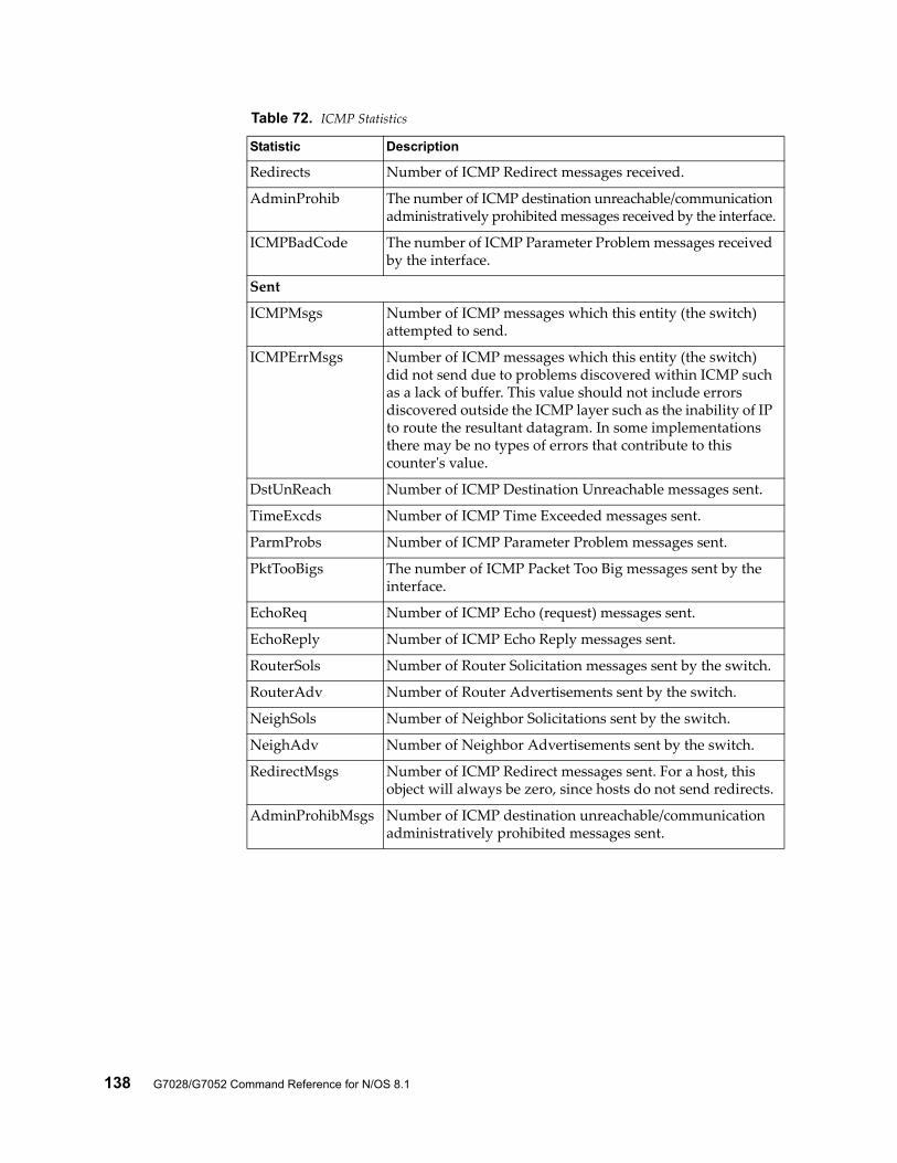
138 G7028/G7052 Command Reference for N/OS 8.1
Redirects Number of ICMP Redirect messages received.
AdminProhib The number of ICMP destination unreachable/communication administratively prohibited messages received by the interface.
ICMPBadCode The number of ICMP Parameter Problem messages received by the interface.
Sent
ICMPMsgs Number of ICMP messages which this entity (the switch) attempted to send.
ICMPErrMsgs Number of ICMP messages which this entity (the switch) did not send due to problems discovered within ICMP such as a lack of buffer. This value should not include errors discovered outside the ICMP layer such as the inability of IP to route the resultant datagram. In some implementations there may be no types of errors that contribute to this counter's value.
DstUnReach Number of ICMP Destination Unreachable messages sent.
TimeExcds Number of ICMP Time Exceeded messages sent.
ParmProbs Number of ICMP Parameter Problem messages sent.
PktTooBigs The number of ICMP Packet Too Big messages sent by the interface.
EchoReq Number of ICMP Echo (request) messages sent.
EchoReply Number of ICMP Echo Reply messages sent.
RouterSols Number of Router Solicitation messages sent by the switch.
RouterAdv Number of Router Advertisements sent by the switch.
NeighSols Number of Neighbor Solicitations sent by the switch.
NeighAdv Number of Neighbor Advertisements sent by the switch.
RedirectMsgs Number of ICMP Redirect messages sent. For a host, this object will always be zero, since hosts do not send redirects.
AdminProhibMsgs Number of ICMP destination unreachable/communication administratively prohibited messages sent.
Table 72. ICMP Statistics
Statistic Description
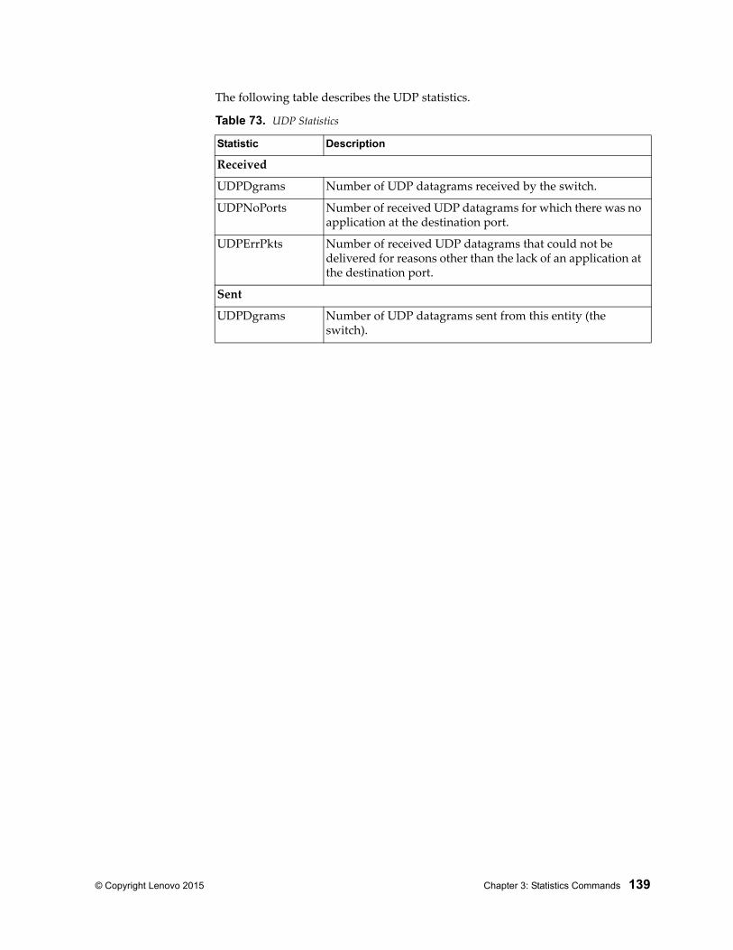
© Copyright Lenovo 2015 Chapter 3: Statistics Commands 139
The following table describes the UDP statistics.
Table 73. UDP Statistics
Statistic Description
Received
UDPDgrams Number of UDP datagrams received by the switch.
UDPNoPorts Number of received UDP datagrams for which there was no application at the destination port.
UDPErrPkts Number of received UDP datagrams that could not be delivered for reasons other than the lack of an application at the destination port.
Sent
UDPDgrams Number of UDP datagrams sent from this entity (the switch).
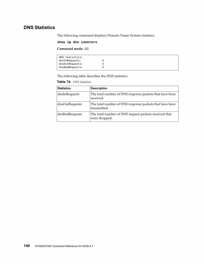
140 G7028/G7052 Command Reference for N/OS 8.1
DNS Statistics
The following command displays Domain Name System statistics.
show ip dns counters
Command mode: All
The following table describes the DNS statistics.
DNS statistics:dnsInRequests: 0dnsOutRequests: 0dnsBadRequests: 0
Table 74. DNS Statistics
Statistics Description
dnsInRequests The total number of DNS response packets that have been received.
dnsOutRequests The total number of DNS response packets that have been transmitted.
dnsBadRequests The total number of DNS request packets received that were dropped.
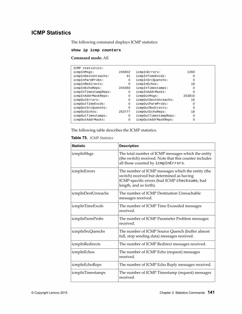
© Copyright Lenovo 2015 Chapter 3: Statistics Commands 141
ICMP Statistics
The following command displays ICMP statistics:
show ip icmp counters
Command mode: All
The following table describes the ICMP statistics.
ICMP statistics:icmpInMsgs: 245802 icmpInErrors: 1393icmpInDestUnreachs: 41 icmpInTimeExcds: 0icmpInParmProbs: 0 icmpInSrcQuenchs: 0icmpInRedirects: 0 icmpInEchos: 18icmpInEchoReps: 244350 icmpInTimestamps: 0icmpInTimestampReps: 0 icmpInAddrMasks: 0icmpInAddrMaskReps: 0 icmpOutMsgs: 253810icmpOutErrors: 0 icmpOutDestUnreachs: 15icmpOutTimeExcds: 0 icmpOutParmProbs: 0icmpOutSrcQuenchs: 0 icmpOutRedirects: 0icmpOutEchos: 253777 icmpOutEchoReps: 18icmpOutTimestamps: 0 icmpOutTimestampReps: 0icmpOutAddrMasks: 0 icmpOutAddrMaskReps: 0
Table 75. ICMP Statistics
Statistic Description
icmpInMsgs The total number of ICMP messages which the entity (the switch) received. Note that this counter includes all those counted by icmpInErrors.
icmpInErrors The number of ICMP messages which the entity (the switch) received but determined as having ICMP-specific errors (bad ICMP checksums, bad length, and so forth).
icmpInDestUnreachs The number of ICMP Destination Unreachable messages received.
icmpInTimeExcds The number of ICMP Time Exceeded messages received.
icmpInParmProbs The number of ICMP Parameter Problem messages received.
icmpInSrcQuenchs The number of ICMP Source Quench (buffer almost full, stop sending data) messages received.
icmpInRedirects The number of ICMP Redirect messages received.
icmpInEchos The number of ICMP Echo (request) messages received.
icmpInEchoReps The number of ICMP Echo Reply messages received.
icmpInTimestamps The number of ICMP Timestamp (request) messages received.
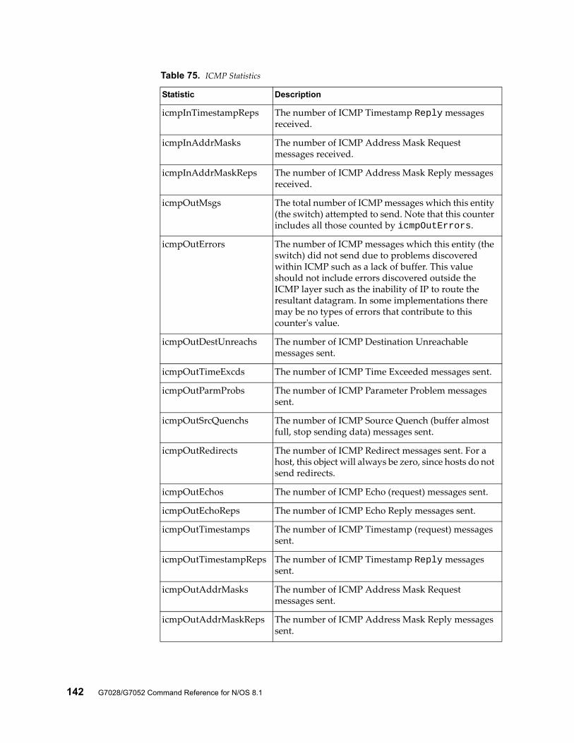
142 G7028/G7052 Command Reference for N/OS 8.1
icmpInTimestampReps The number of ICMP Timestamp Reply messages received.
icmpInAddrMasks The number of ICMP Address Mask Request messages received.
icmpInAddrMaskReps The number of ICMP Address Mask Reply messages received.
icmpOutMsgs The total number of ICMP messages which this entity (the switch) attempted to send. Note that this counter includes all those counted by icmpOutErrors.
icmpOutErrors The number of ICMP messages which this entity (the switch) did not send due to problems discovered within ICMP such as a lack of buffer. This value should not include errors discovered outside the ICMP layer such as the inability of IP to route the resultant datagram. In some implementations there may be no types of errors that contribute to this counter's value.
icmpOutDestUnreachs The number of ICMP Destination Unreachable messages sent.
icmpOutTimeExcds The number of ICMP Time Exceeded messages sent.
icmpOutParmProbs The number of ICMP Parameter Problem messages sent.
icmpOutSrcQuenchs The number of ICMP Source Quench (buffer almost full, stop sending data) messages sent.
icmpOutRedirects The number of ICMP Redirect messages sent. For a host, this object will always be zero, since hosts do not send redirects.
icmpOutEchos The number of ICMP Echo (request) messages sent.
icmpOutEchoReps The number of ICMP Echo Reply messages sent.
icmpOutTimestamps The number of ICMP Timestamp (request) messages sent.
icmpOutTimestampReps The number of ICMP Timestamp Reply messages sent.
icmpOutAddrMasks The number of ICMP Address Mask Request messages sent.
icmpOutAddrMaskReps The number of ICMP Address Mask Reply messages sent.
Table 75. ICMP Statistics
Statistic Description
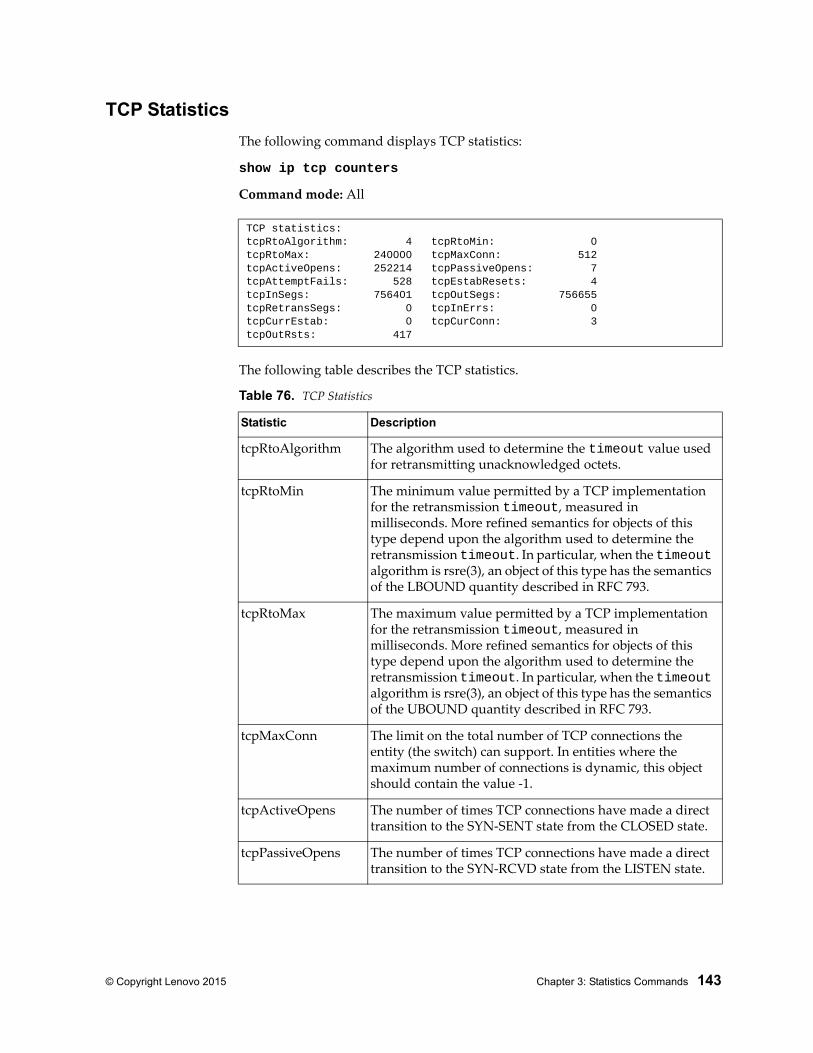
© Copyright Lenovo 2015 Chapter 3: Statistics Commands 143
TCP Statistics
The following command displays TCP statistics:
show ip tcp counters
Command mode: All
The following table describes the TCP statistics.
TCP statistics:tcpRtoAlgorithm: 4 tcpRtoMin: 0tcpRtoMax: 240000 tcpMaxConn: 512tcpActiveOpens: 252214 tcpPassiveOpens: 7tcpAttemptFails: 528 tcpEstabResets: 4tcpInSegs: 756401 tcpOutSegs: 756655tcpRetransSegs: 0 tcpInErrs: 0tcpCurrEstab: 0 tcpCurConn: 3tcpOutRsts: 417
Table 76. TCP Statistics
Statistic Description
tcpRtoAlgorithm The algorithm used to determine the timeout value used for retransmitting unacknowledged octets.
tcpRtoMin The minimum value permitted by a TCP implementation for the retransmission timeout, measured in milliseconds. More refined semantics for objects of this type depend upon the algorithm used to determine the retransmission timeout. In particular, when the timeout algorithm is rsre(3), an object of this type has the semantics of the LBOUND quantity described in RFC 793.
tcpRtoMax The maximum value permitted by a TCP implementation for the retransmission timeout, measured in milliseconds. More refined semantics for objects of this type depend upon the algorithm used to determine the retransmission timeout. In particular, when the timeout algorithm is rsre(3), an object of this type has the semantics of the UBOUND quantity described in RFC 793.
tcpMaxConn The limit on the total number of TCP connections the entity (the switch) can support. In entities where the maximum number of connections is dynamic, this object should contain the value -1.
tcpActiveOpens The number of times TCP connections have made a direct transition to the SYN-SENT state from the CLOSED state.
tcpPassiveOpens The number of times TCP connections have made a direct transition to the SYN-RCVD state from the LISTEN state.
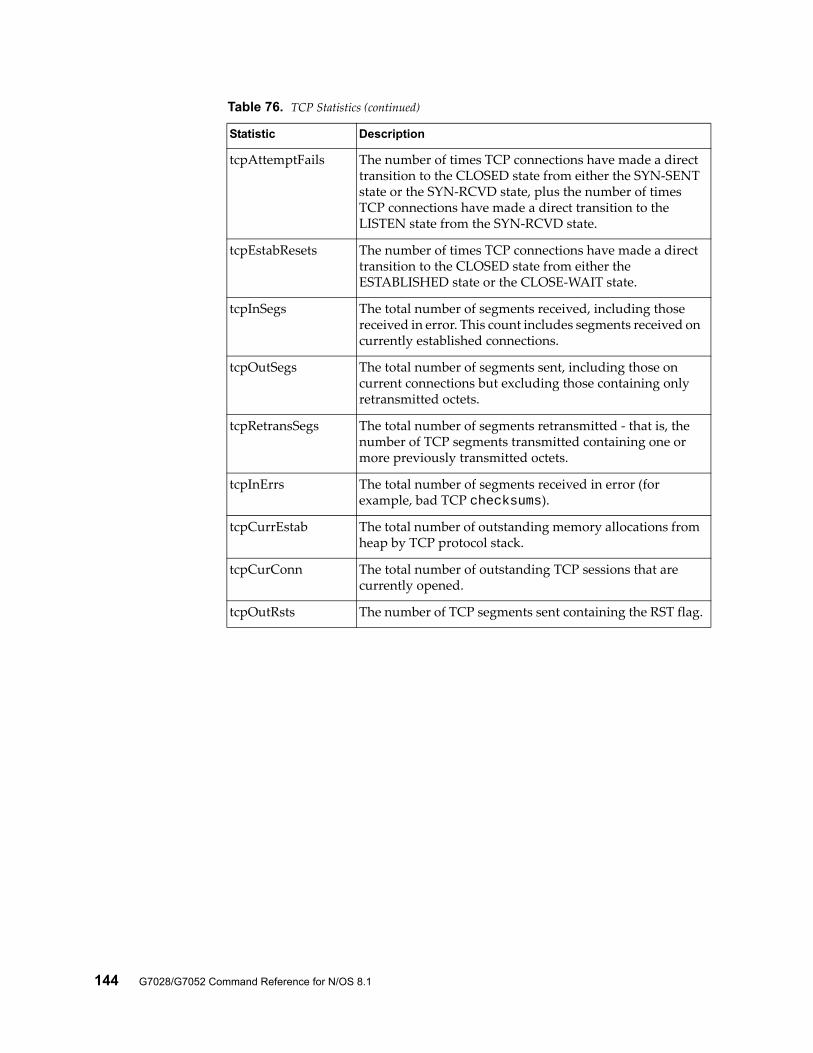
144 G7028/G7052 Command Reference for N/OS 8.1
tcpAttemptFails The number of times TCP connections have made a direct transition to the CLOSED state from either the SYN-SENT state or the SYN-RCVD state, plus the number of times TCP connections have made a direct transition to the LISTEN state from the SYN-RCVD state.
tcpEstabResets The number of times TCP connections have made a direct transition to the CLOSED state from either the ESTABLISHED state or the CLOSE-WAIT state.
tcpInSegs The total number of segments received, including those received in error. This count includes segments received on currently established connections.
tcpOutSegs The total number of segments sent, including those on current connections but excluding those containing only retransmitted octets.
tcpRetransSegs The total number of segments retransmitted - that is, the number of TCP segments transmitted containing one or more previously transmitted octets.
tcpInErrs The total number of segments received in error (for example, bad TCP checksums).
tcpCurrEstab The total number of outstanding memory allocations from heap by TCP protocol stack.
tcpCurConn The total number of outstanding TCP sessions that are currently opened.
tcpOutRsts The number of TCP segments sent containing the RST flag.
Table 76. TCP Statistics (continued)
Statistic Description
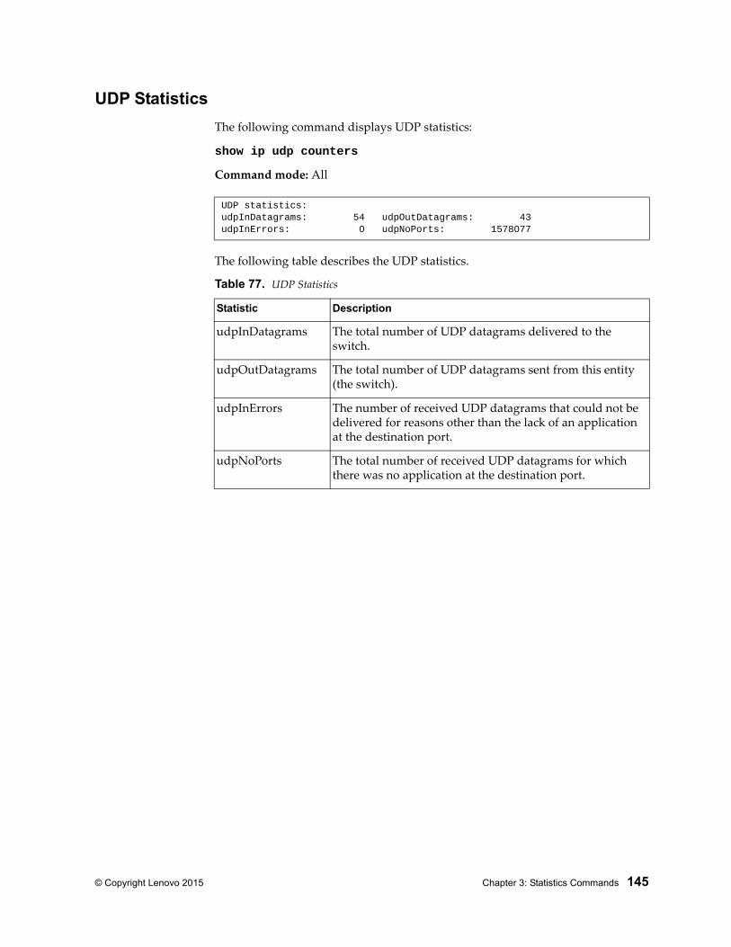
© Copyright Lenovo 2015 Chapter 3: Statistics Commands 145
UDP Statistics
The following command displays UDP statistics:
show ip udp counters
Command mode: All
The following table describes the UDP statistics.
UDP statistics:udpInDatagrams: 54 udpOutDatagrams: 43udpInErrors: 0 udpNoPorts: 1578077
Table 77. UDP Statistics
Statistic Description
udpInDatagrams The total number of UDP datagrams delivered to the switch.
udpOutDatagrams The total number of UDP datagrams sent from this entity (the switch).
udpInErrors The number of received UDP datagrams that could not be delivered for reasons other than the lack of an application at the destination port.
udpNoPorts The total number of received UDP datagrams for which there was no application at the destination port.
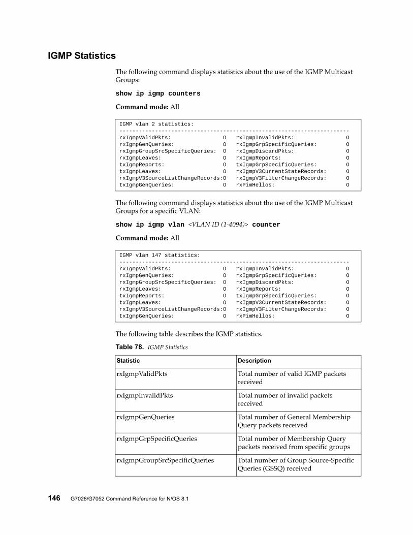
146 G7028/G7052 Command Reference for N/OS 8.1
IGMP Statistics
The following command displays statistics about the use of the IGMP Multicast Groups:
show ip igmp counters
Command mode: All
The following command displays statistics about the use of the IGMP Multicast Groups for a specific VLAN:
show ip igmp vlan <VLAN ID (1-4094)> counter
Command mode: All
The following table describes the IGMP statistics.
IGMP vlan 2 statistics:-----------------------------------------------------------------------rxIgmpValidPkts: 0 rxIgmpInvalidPkts: 0rxIgmpGenQueries: 0 rxIgmpGrpSpecificQueries: 0rxIgmpGroupSrcSpecificQueries: 0 rxIgmpDiscardPkts: 0rxIgmpLeaves: 0 rxIgmpReports: 0txIgmpReports: 0 txIgmpGrpSpecificQueries: 0txIgmpLeaves: 0 rxIgmpV3CurrentStateRecords: 0rxIgmpV3SourceListChangeRecords:0 rxIgmpV3FilterChangeRecords: 0txIgmpGenQueries: 0 rxPimHellos: 0
IGMP vlan 147 statistics:-----------------------------------------------------------------------rxIgmpValidPkts: 0 rxIgmpInvalidPkts: 0rxIgmpGenQueries: 0 rxIgmpGrpSpecificQueries: 0rxIgmpGroupSrcSpecificQueries: 0 rxIgmpDiscardPkts: 0rxIgmpLeaves: 0 rxIgmpReports: 0txIgmpReports: 0 txIgmpGrpSpecificQueries: 0txIgmpLeaves: 0 rxIgmpV3CurrentStateRecords: 0rxIgmpV3SourceListChangeRecords:0 rxIgmpV3FilterChangeRecords: 0txIgmpGenQueries: 0 rxPimHellos: 0
Table 78. IGMP Statistics
Statistic Description
rxIgmpValidPkts Total number of valid IGMP packets received
rxIgmpInvalidPkts Total number of invalid packets received
rxIgmpGenQueries Total number of General Membership Query packets received
rxIgmpGrpSpecificQueries Total number of Membership Query packets received from specific groups
rxIgmpGroupSrcSpecificQueries Total number of Group Source-Specific Queries (GSSQ) received
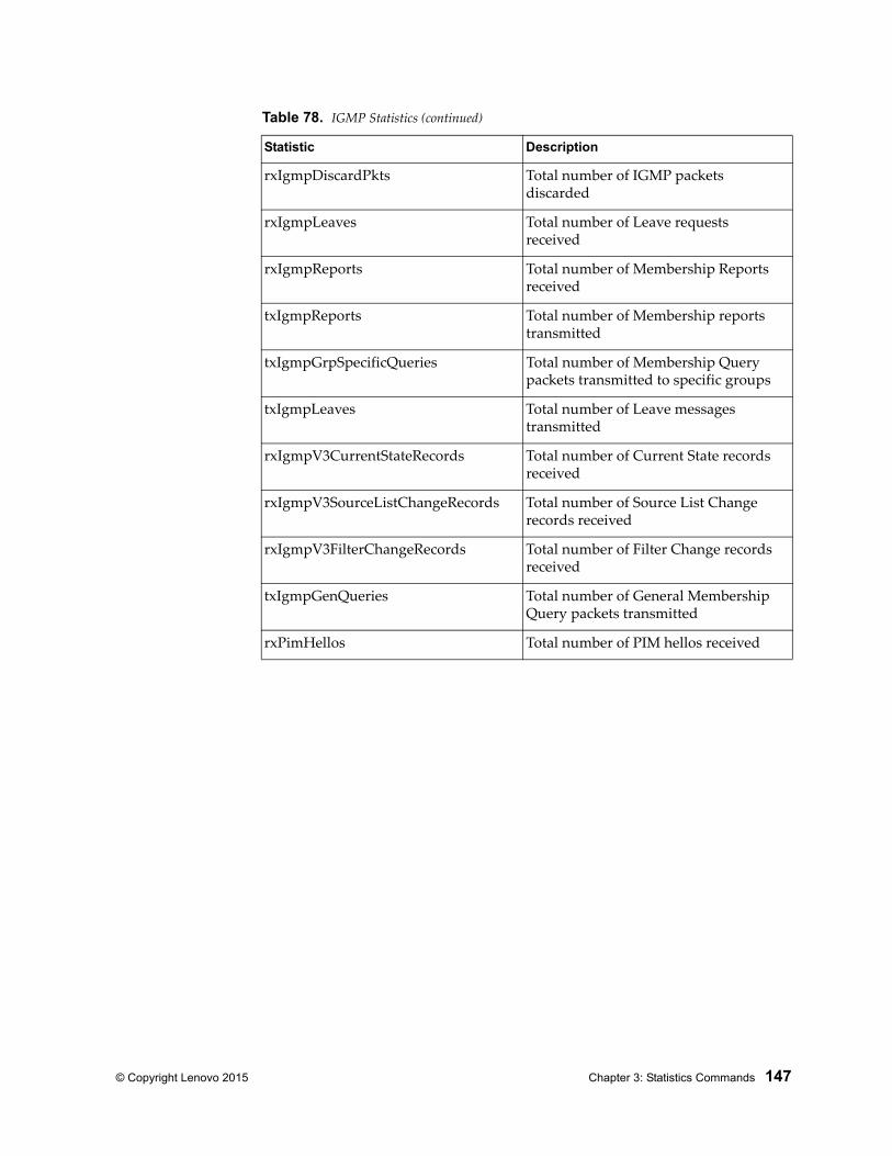
© Copyright Lenovo 2015 Chapter 3: Statistics Commands 147
rxIgmpDiscardPkts Total number of IGMP packets discarded
rxIgmpLeaves Total number of Leave requests received
rxIgmpReports Total number of Membership Reports received
txIgmpReports Total number of Membership reports transmitted
txIgmpGrpSpecificQueries Total number of Membership Query packets transmitted to specific groups
txIgmpLeaves Total number of Leave messages transmitted
rxIgmpV3CurrentStateRecords Total number of Current State records received
rxIgmpV3SourceListChangeRecords Total number of Source List Change records received
rxIgmpV3FilterChangeRecords Total number of Filter Change records received
txIgmpGenQueries Total number of General Membership Query packets transmitted
rxPimHellos Total number of PIM hellos received
Table 78. IGMP Statistics (continued)
Statistic Description
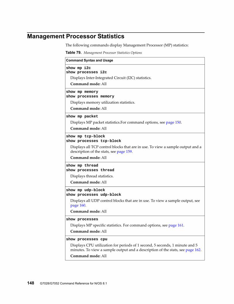
148 G7028/G7052 Command Reference for N/OS 8.1
Management Processor StatisticsThe following commands display Management Processor (MP) statistics:
Table 79. Management Processor Statistics Options
Command Syntax and Usage
show mp i2cshow processes i2c
Displays Inter-Integrated Circuit (I2C) statistics.Command mode: All
show mp memoryshow processes memory
Displays memory utilization statistics.Command mode: All
show mp packet
Displays MP packet statistics.For command options, see page 150.Command mode: All
show mp tcp-blockshow processes tcp-block
Displays all TCP control blocks that are in use. To view a sample output and a description of the stats, see page 159.Command mode: All
show mp threadshow processes thread
Displays thread statistics.Command mode: All
show mp udp-blockshow processes udp-block
Displays all UDP control blocks that are in use. To view a sample output, see page 160.Command mode: All
show processes
Displays MP specific statistics. For command options, see page 161.Command mode: All
show processes cpu
Displays CPU utilization for periods of 1 second, 5 seconds, 1 minute and 5 minutes. To view a sample output and a description of the stats, see page 162.Command mode: All
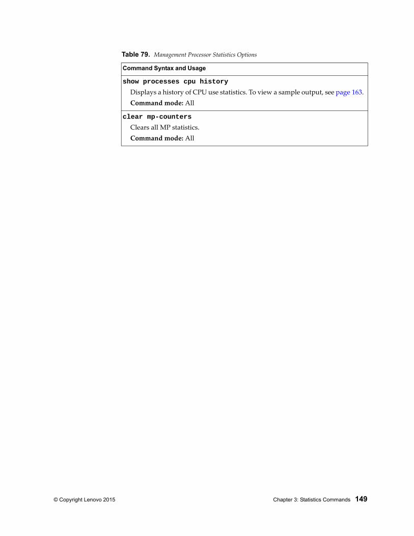
© Copyright Lenovo 2015 Chapter 3: Statistics Commands 149
show processes cpu history
Displays a history of CPU use statistics. To view a sample output, see page 163.Command mode: All
clear mp-counters
Clears all MP statistics.Command mode: All
Table 79. Management Processor Statistics Options
Command Syntax and Usage
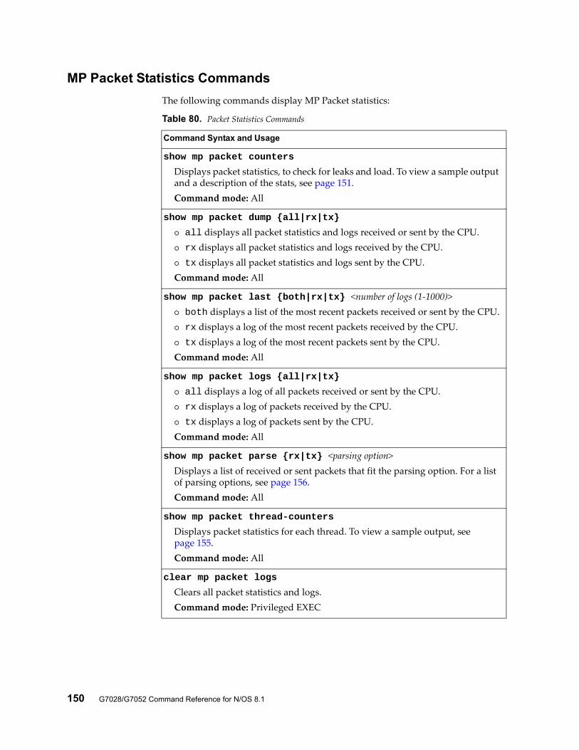
150 G7028/G7052 Command Reference for N/OS 8.1
MP Packet Statistics Commands
The following commands display MP Packet statistics:
Table 80. Packet Statistics Commands
Command Syntax and Usage
show mp packet counters
Displays packet statistics, to check for leaks and load. To view a sample output and a description of the stats, see page 151. Command mode: All
show mp packet dump {all|rx|tx}
all displays all packet statistics and logs received or sent by the CPU. rx displays all packet statistics and logs received by the CPU. tx displays all packet statistics and logs sent by the CPU.Command mode: All
show mp packet last {both|rx|tx} <number of logs (1-1000)> both displays a list of the most recent packets received or sent by the CPU. rx displays a log of the most recent packets received by the CPU. tx displays a log of the most recent packets sent by the CPU.Command mode: All
show mp packet logs {all|rx|tx}
all displays a log of all packets received or sent by the CPU. rx displays a log of packets received by the CPU. tx displays a log of packets sent by the CPU.Command mode: All
show mp packet parse {rx|tx} <parsing option>Displays a list of received or sent packets that fit the parsing option. For a list of parsing options, see page 156.Command mode: All
show mp packet thread-counters
Displays packet statistics for each thread. To view a sample output, see page 155.Command mode: All
clear mp packet logs
Clears all packet statistics and logs.Command mode: Privileged EXEC
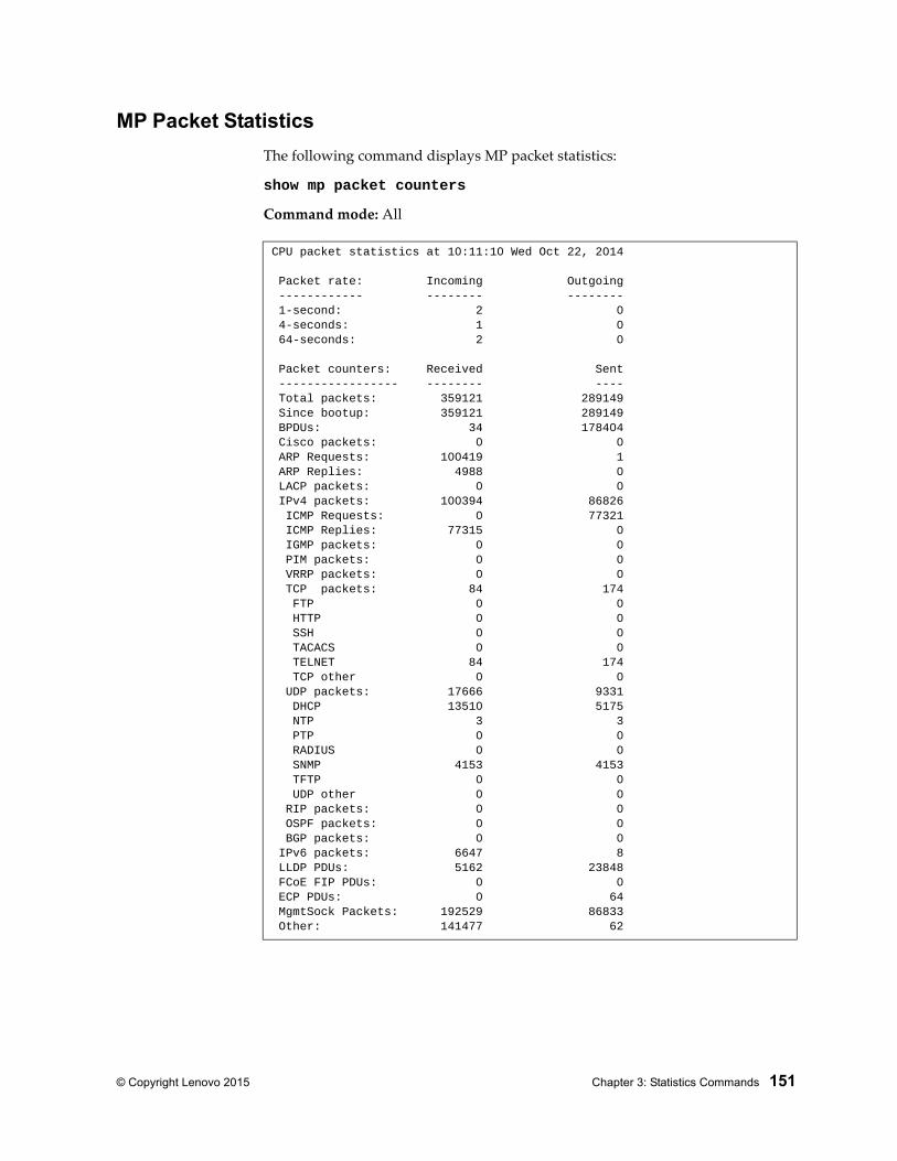
© Copyright Lenovo 2015 Chapter 3: Statistics Commands 151
MP Packet Statistics
The following command displays MP packet statistics:
show mp packet counters
Command mode: All
CPU packet statistics at 10:11:10 Wed Oct 22, 2014
Packet rate: Incoming Outgoing ------------ -------- -------- 1-second: 2 0 4-seconds: 1 0 64-seconds: 2 0
Packet counters: Received Sent ----------------- -------- ---- Total packets: 359121 289149 Since bootup: 359121 289149 BPDUs: 34 178404 Cisco packets: 0 0 ARP Requests: 100419 1 ARP Replies: 4988 0 LACP packets: 0 0 IPv4 packets: 100394 86826 ICMP Requests: 0 77321 ICMP Replies: 77315 0 IGMP packets: 0 0 PIM packets: 0 0 VRRP packets: 0 0 TCP packets: 84 174 FTP 0 0 HTTP 0 0 SSH 0 0 TACACS 0 0 TELNET 84 174 TCP other 0 0 UDP packets: 17666 9331 DHCP 13510 5175 NTP 3 3 PTP 0 0 RADIUS 0 0 SNMP 4153 4153 TFTP 0 0 UDP other 0 0 RIP packets: 0 0 OSPF packets: 0 0 BGP packets: 0 0 IPv6 packets: 6647 8 LLDP PDUs: 5162 23848 FCoE FIP PDUs: 0 0 ECP PDUs: 0 64 MgmtSock Packets: 192529 86833 Other: 141477 62
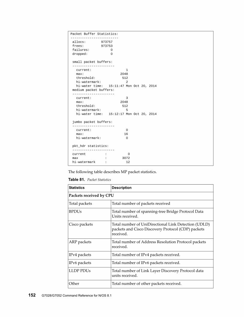
152 G7028/G7052 Command Reference for N/OS 8.1
The following table describes MP packet statistics.
Packet Buffer Statistics:------------------------- allocs: 973757 frees: 973753 failures: 0 dropped: 0
small packet buffers: ---------------------- current: 1 max: 2048 threshold: 512 hi-watermark: 2 hi-water time: 15:11:47 Mon Oct 20, 2014 medium packet buffers: ---------------------- current: 3 max: 2048 threshold: 512 hi-watermark: 5 hi-water time: 15:12:17 Mon Oct 20, 2014
jumbo packet buffers: ---------------------- current: 0 max: 16 hi-watermark: 0
pkt_hdr statistics: ---------------------- current : 0 max : 3072 hi-watermark : 12
Table 81. Packet Statistics
Statistics Description
Packets received by CPU
Total packets Total number of packets received
BPDUs Total number of spanning-tree Bridge Protocol Data Units received.
Cisco packets Total number of UniDirectional Link Detection (UDLD) packets and Cisco Discovery Protocol (CDP) packets received.
ARP packets Total number of Address Resolution Protocol packets received.
IPv4 packets Total number of IPv4 packets received.
IPv6 packets Total number of IPv6 packets received.
LLDP PDUs Total number of Link Layer Discovery Protocol data units received.
Other Total number of other packets received.
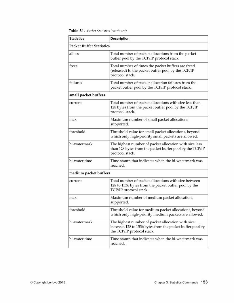
© Copyright Lenovo 2015 Chapter 3: Statistics Commands 153
Packet Buffer Statistics
allocs Total number of packet allocations from the packet buffer pool by the TCP/IP protocol stack.
frees Total number of times the packet buffers are freed (released) to the packet buffer pool by the TCP/IP protocol stack.
failures Total number of packet allocation failures from the packet buffer pool by the TCP/IP protocol stack.
small packet buffers
current Total number of packet allocations with size less than 128 bytes from the packet buffer pool by the TCP/IP protocol stack.
max Maximum number of small packet allocations supported.
threshold Threshold value for small packet allocations, beyond which only high-priority small packets are allowed.
hi-watermark The highest number of packet allocation with size less than 128 bytes from the packet buffer pool by the TCP/IP protocol stack.
hi-water time Time stamp that indicates when the hi-watermark was reached.
medium packet buffers
current Total number of packet allocations with size between 128 to 1536 bytes from the packet buffer pool by the TCP/IP protocol stack.
max Maximum number of medium packet allocations supported.
threshold Threshold value for medium packet allocations, beyond which only high-priority medium packets are allowed.
hi-watermark The highest number of packet allocation with size between 128 to 1536 bytes from the packet buffer pool by the TCP/IP protocol stack.
hi-water time Time stamp that indicates when the hi-watermark was reached.
Table 81. Packet Statistics (continued)
Statistics Description
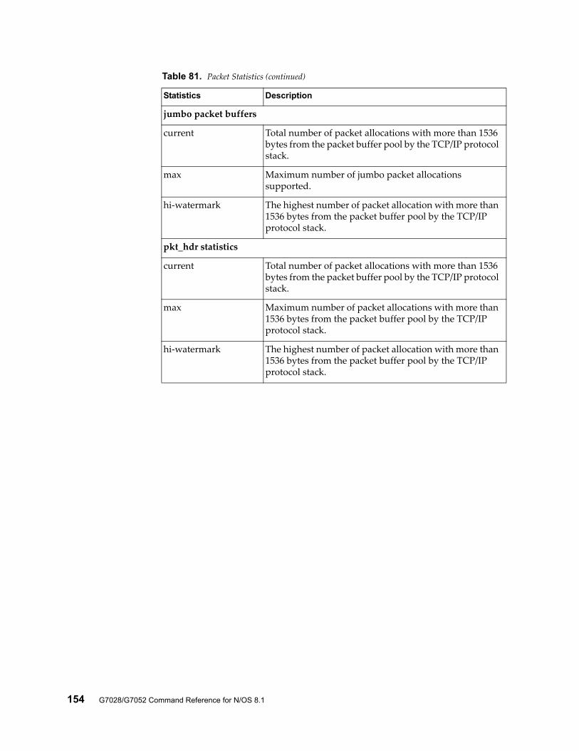
154 G7028/G7052 Command Reference for N/OS 8.1
jumbo packet buffers
current Total number of packet allocations with more than 1536 bytes from the packet buffer pool by the TCP/IP protocol stack.
max Maximum number of jumbo packet allocations supported.
hi-watermark The highest number of packet allocation with more than 1536 bytes from the packet buffer pool by the TCP/IP protocol stack.
pkt_hdr statistics
current Total number of packet allocations with more than 1536 bytes from the packet buffer pool by the TCP/IP protocol stack.
max Maximum number of packet allocations with more than 1536 bytes from the packet buffer pool by the TCP/IP protocol stack.
hi-watermark The highest number of packet allocation with more than 1536 bytes from the packet buffer pool by the TCP/IP protocol stack.
Table 81. Packet Statistics (continued)
Statistics Description
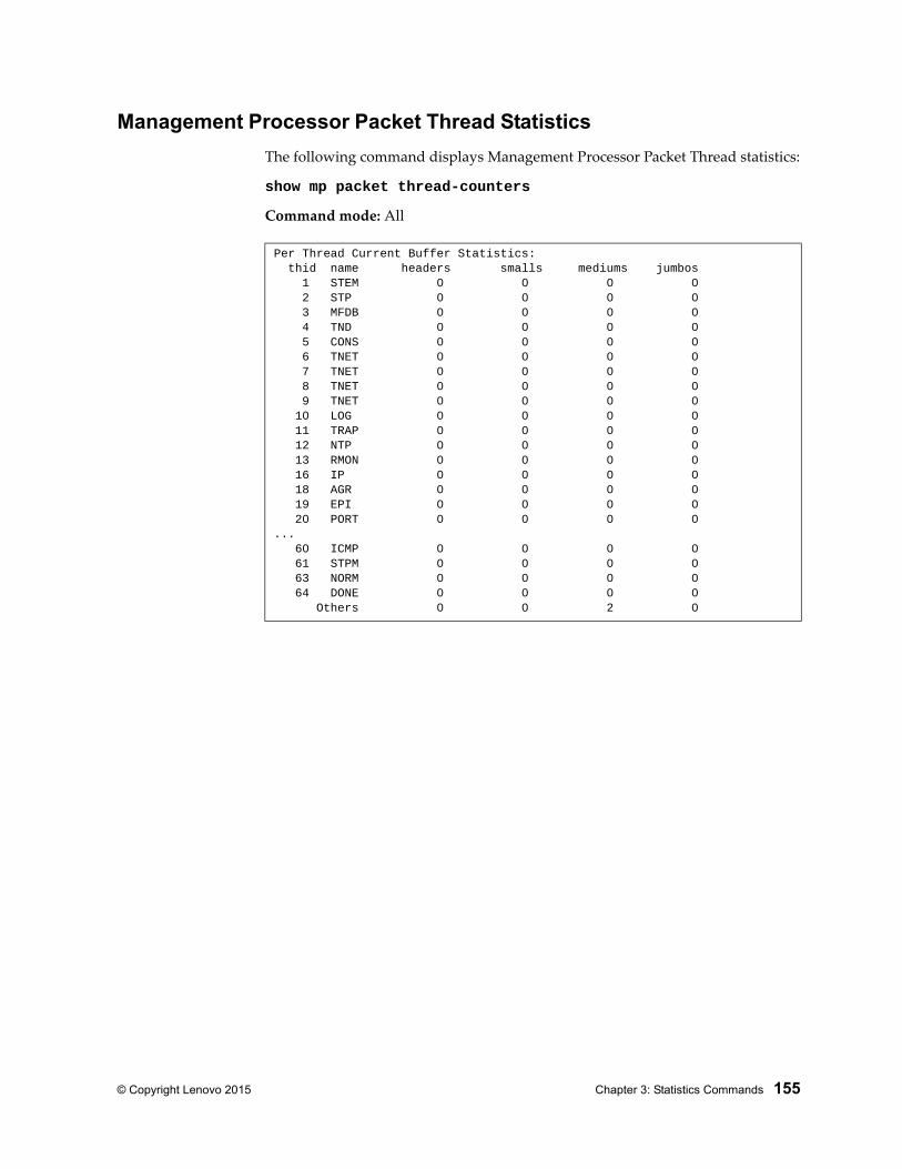
© Copyright Lenovo 2015 Chapter 3: Statistics Commands 155
Management Processor Packet Thread Statistics
The following command displays Management Processor Packet Thread statistics:
show mp packet thread-counters
Command mode: All
Per Thread Current Buffer Statistics: thid name headers smalls mediums jumbos 1 STEM 0 0 0 0 2 STP 0 0 0 0 3 MFDB 0 0 0 0 4 TND 0 0 0 0 5 CONS 0 0 0 0 6 TNET 0 0 0 0 7 TNET 0 0 0 0 8 TNET 0 0 0 0 9 TNET 0 0 0 0 10 LOG 0 0 0 0 11 TRAP 0 0 0 0 12 NTP 0 0 0 0 13 RMON 0 0 0 0 16 IP 0 0 0 0 18 AGR 0 0 0 0 19 EPI 0 0 0 0 20 PORT 0 0 0 0... 60 ICMP 0 0 0 0 61 STPM 0 0 0 0 63 NORM 0 0 0 0 64 DONE 0 0 0 0 Others 0 0 2 0
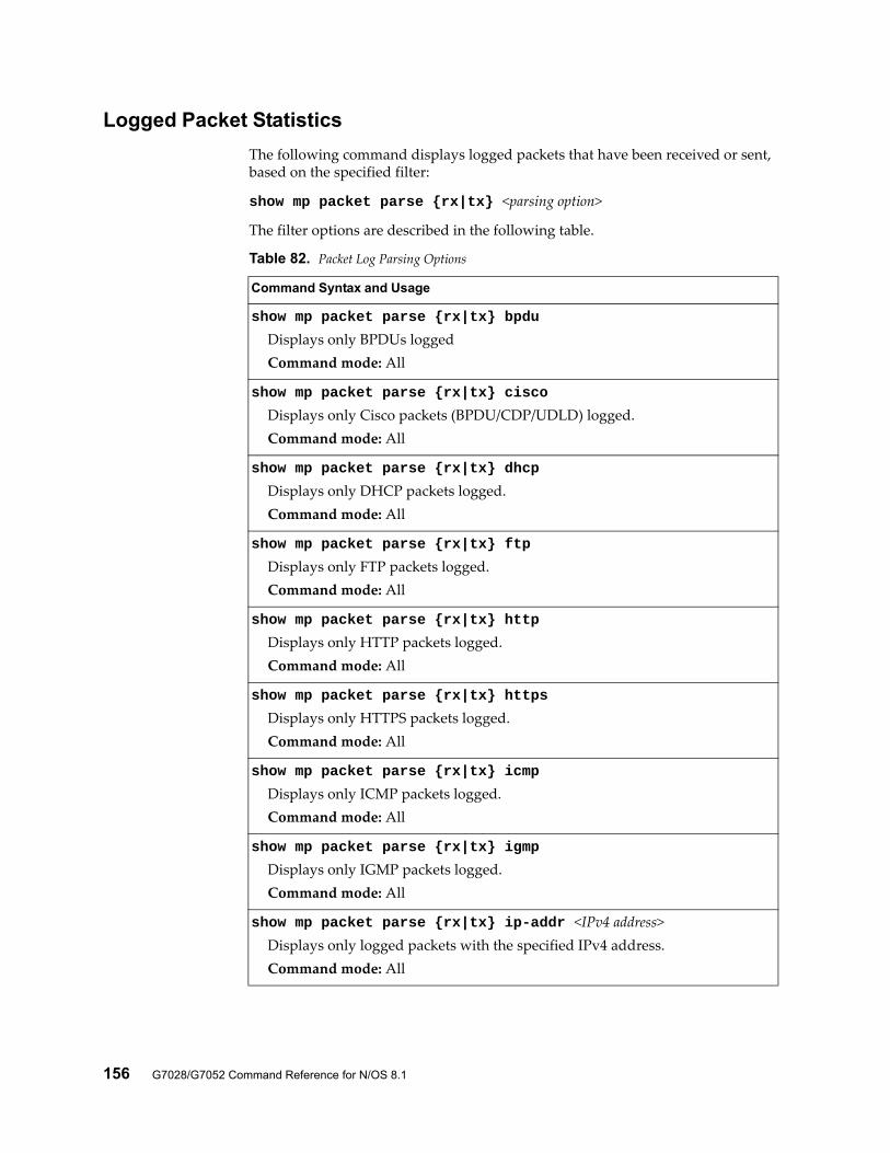
156 G7028/G7052 Command Reference for N/OS 8.1
Logged Packet Statistics
The following command displays logged packets that have been received or sent, based on the specified filter:
show mp packet parse {rx|tx} <parsing option>
The filter options are described in the following table.
Table 82. Packet Log Parsing Options
Command Syntax and Usage
show mp packet parse {rx|tx} bpdu
Displays only BPDUs loggedCommand mode: All
show mp packet parse {rx|tx} cisco
Displays only Cisco packets (BPDU/CDP/UDLD) logged.Command mode: All
show mp packet parse {rx|tx} dhcp
Displays only DHCP packets logged.Command mode: All
show mp packet parse {rx|tx} ftp
Displays only FTP packets logged.Command mode: All
show mp packet parse {rx|tx} http
Displays only HTTP packets logged.Command mode: All
show mp packet parse {rx|tx} https
Displays only HTTPS packets logged.Command mode: All
show mp packet parse {rx|tx} icmp
Displays only ICMP packets logged.Command mode: All
show mp packet parse {rx|tx} igmp
Displays only IGMP packets logged.Command mode: All
show mp packet parse {rx|tx} ip-addr <IPv4 address>Displays only logged packets with the specified IPv4 address.Command mode: All
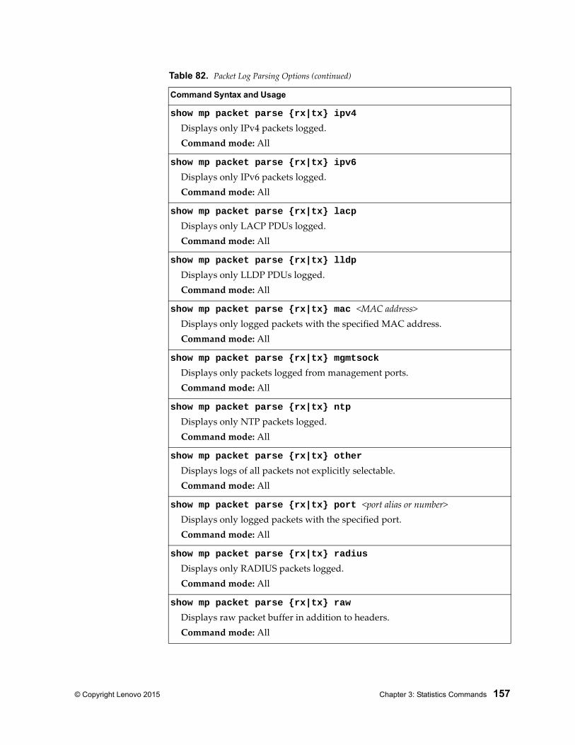
© Copyright Lenovo 2015 Chapter 3: Statistics Commands 157
show mp packet parse {rx|tx} ipv4
Displays only IPv4 packets logged.Command mode: All
show mp packet parse {rx|tx} ipv6
Displays only IPv6 packets logged.Command mode: All
show mp packet parse {rx|tx} lacp
Displays only LACP PDUs logged.Command mode: All
show mp packet parse {rx|tx} lldp
Displays only LLDP PDUs logged.Command mode: All
show mp packet parse {rx|tx} mac <MAC address>Displays only logged packets with the specified MAC address.Command mode: All
show mp packet parse {rx|tx} mgmtsock
Displays only packets logged from management ports.Command mode: All
show mp packet parse {rx|tx} ntp
Displays only NTP packets logged.Command mode: All
show mp packet parse {rx|tx} other
Displays logs of all packets not explicitly selectable.Command mode: All
show mp packet parse {rx|tx} port <port alias or number>Displays only logged packets with the specified port.Command mode: All
show mp packet parse {rx|tx} radius
Displays only RADIUS packets logged.Command mode: All
show mp packet parse {rx|tx} raw
Displays raw packet buffer in addition to headers.Command mode: All
Table 82. Packet Log Parsing Options (continued)
Command Syntax and Usage
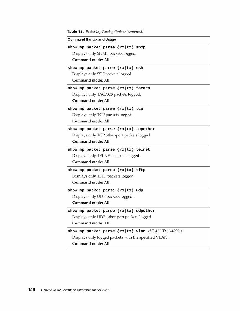
158 G7028/G7052 Command Reference for N/OS 8.1
show mp packet parse {rx|tx} snmp
Displays only SNMP packets logged.Command mode: All
show mp packet parse {rx|tx} ssh
Displays only SSH packets logged.Command mode: All
show mp packet parse {rx|tx} tacacs
Displays only TACACS packets logged.Command mode: All
show mp packet parse {rx|tx} tcp
Displays only TCP packets logged.Command mode: All
show mp packet parse {rx|tx} tcpother
Displays only TCP other-port packets logged.Command mode: All
show mp packet parse {rx|tx} telnet
Displays only TELNET packets logged.Command mode: All
show mp packet parse {rx|tx} tftp
Displays only TFTP packets logged.Command mode: All
show mp packet parse {rx|tx} udp
Displays only UDP packets logged.Command mode: All
show mp packet parse {rx|tx} udpother
Displays only UDP other-port packets logged.Command mode: All
show mp packet parse {rx|tx} vlan <VLAN ID (1-4095)>Displays only logged packets with the specified VLAN.Command mode: All
Table 82. Packet Log Parsing Options (continued)
Command Syntax and Usage
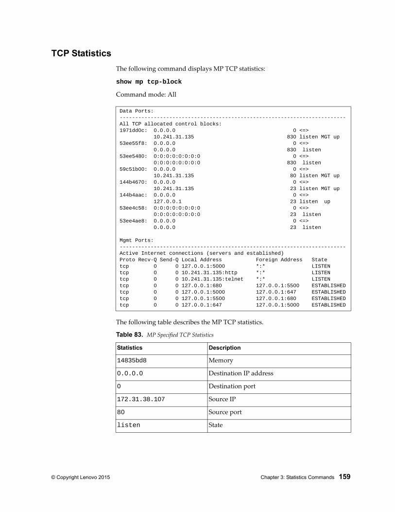
© Copyright Lenovo 2015 Chapter 3: Statistics Commands 159
TCP Statistics
The following command displays MP TCP statistics:
show mp tcp-block
Command mode: All
The following table describes the MP TCP statistics.
Data Ports:-------------------------------------------------------------------------All TCP allocated control blocks:1971dd0c: 0.0.0.0 0 <=> 10.241.31.135 830 listen MGT up53ee55f8: 0.0.0.0 0 <=> 0.0.0.0 830 listen53ee5480: 0:0:0:0:0:0:0:0 0 <=> 0:0:0:0:0:0:0:0 830 listen59c51b00: 0.0.0.0 0 <=> 10.241.31.135 80 listen MGT up144b4670: 0.0.0.0 0 <=> 10.241.31.135 23 listen MGT up144b4aac: 0.0.0.0 0 <=> 127.0.0.1 23 listen up53ee4c58: 0:0:0:0:0:0:0:0 0 <=> 0:0:0:0:0:0:0:0 23 listen53ee4ae8: 0.0.0.0 0 <=> 0.0.0.0 23 listen
Mgmt Ports:-------------------------------------------------------------------------Active Internet connections (servers and established)Proto Recv-Q Send-Q Local Address Foreign Address Statetcp 0 0 127.0.0.1:5000 *:* LISTENtcp 0 0 10.241.31.135:http *:* LISTENtcp 0 0 10.241.31.135:telnet *:* LISTENtcp 0 0 127.0.0.1:680 127.0.0.1:5500 ESTABLISHEDtcp 0 0 127.0.0.1:5000 127.0.0.1:647 ESTABLISHEDtcp 0 0 127.0.0.1:5500 127.0.0.1:680 ESTABLISHEDtcp 0 0 127.0.0.1:647 127.0.0.1:5000 ESTABLISHED
Table 83. MP Specified TCP Statistics
Statistics Description
14835bd8 Memory
0.0.0.0 Destination IP address
0 Destination port
172.31.38.107 Source IP
80 Source port
listen State
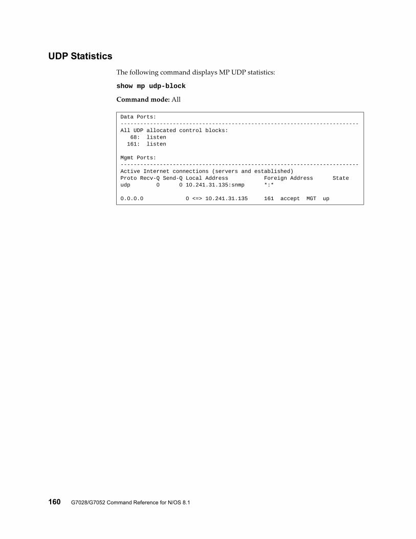
160 G7028/G7052 Command Reference for N/OS 8.1
UDP Statistics
The following command displays MP UDP statistics:
show mp udp-block
Command mode: All
Data Ports:-------------------------------------------------------------------------All UDP allocated control blocks: 68: listen 161: listen
Mgmt Ports:-------------------------------------------------------------------------Active Internet connections (servers and established)Proto Recv-Q Send-Q Local Address Foreign Address Stateudp 0 0 10.241.31.135:snmp *:*
0.0.0.0 0 <=> 10.241.31.135 161 accept MGT up
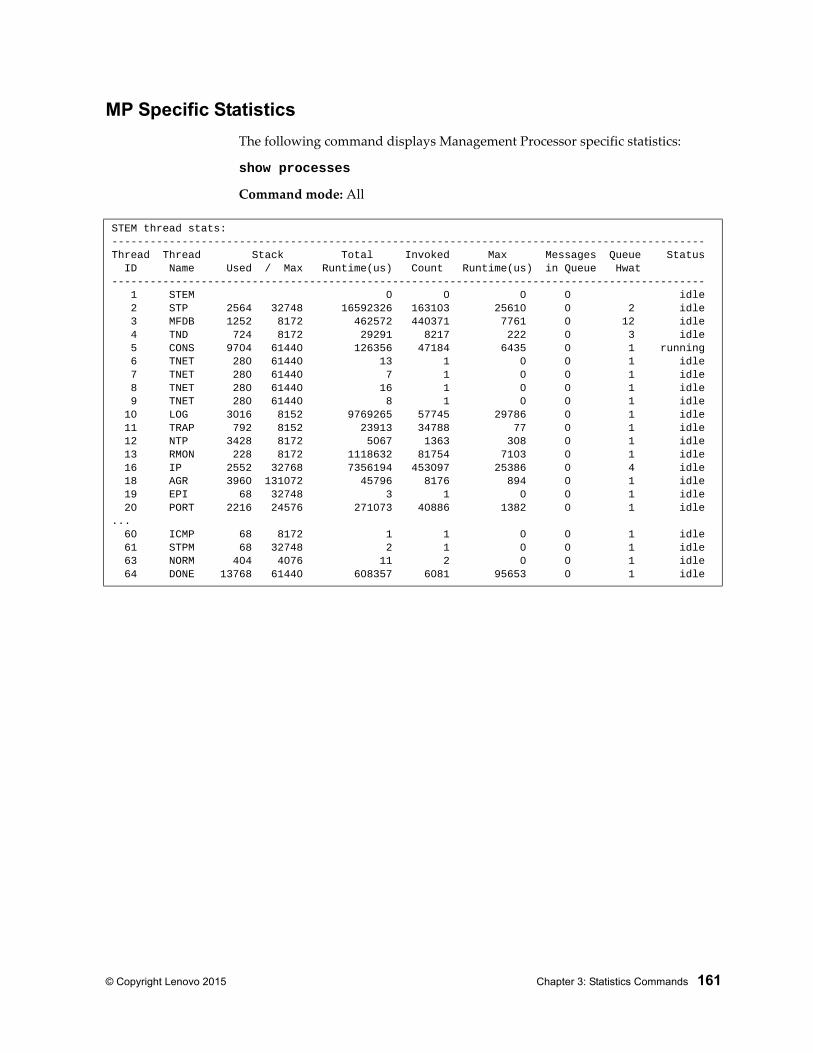
© Copyright Lenovo 2015 Chapter 3: Statistics Commands 161
MP Specific Statistics
The following command displays Management Processor specific statistics:
show processes
Command mode: All
STEM thread stats:---------------------------------------------------------------------------------------------Thread Thread Stack Total Invoked Max Messages Queue Status ID Name Used / Max Runtime(us) Count Runtime(us) in Queue Hwat--------------------------------------------------------------------------------------------- 1 STEM 0 0 0 0 idle 2 STP 2564 32748 16592326 163103 25610 0 2 idle 3 MFDB 1252 8172 462572 440371 7761 0 12 idle 4 TND 724 8172 29291 8217 222 0 3 idle 5 CONS 9704 61440 126356 47184 6435 0 1 running 6 TNET 280 61440 13 1 0 0 1 idle 7 TNET 280 61440 7 1 0 0 1 idle 8 TNET 280 61440 16 1 0 0 1 idle 9 TNET 280 61440 8 1 0 0 1 idle 10 LOG 3016 8152 9769265 57745 29786 0 1 idle 11 TRAP 792 8152 23913 34788 77 0 1 idle 12 NTP 3428 8172 5067 1363 308 0 1 idle 13 RMON 228 8172 1118632 81754 7103 0 1 idle 16 IP 2552 32768 7356194 453097 25386 0 4 idle 18 AGR 3960 131072 45796 8176 894 0 1 idle 19 EPI 68 32748 3 1 0 0 1 idle 20 PORT 2216 24576 271073 40886 1382 0 1 idle... 60 ICMP 68 8172 1 1 0 0 1 idle 61 STPM 68 32748 2 1 0 0 1 idle 63 NORM 404 4076 11 2 0 0 1 idle 64 DONE 13768 61440 608357 6081 95653 0 1 idle
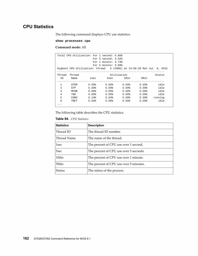
162 G7028/G7052 Command Reference for N/OS 8.1
CPU Statistics
The following command displays CPU use statistics:
show processes cpu
Command mode: All
The following table describes the CPU statistics.
Total CPU Utilization: For 1 second: 0.66% For 5 second: 3.02% For 1 minute: 3.73% For 5 minute: 3.69%Highest CPU Utilization: thread 5 (CONS) at 14:06:29 Mon Jul 6, 2015---------------------------------------------------------------------Thread Thread Utilization Status ID Name 1sec 5sec 1Min 5Min--------------------------------------------------------------------- 1 STEM 0.00% 0.00% 0.00% 0.00% idle 2 STP 0.00% 0.00% 0.00% 0.00% idle 3 MFDB 0.00% 0.00% 0.00% 0.00% idle 4 TND 0.00% 0.00% 0.00% 0.00% idle 5 CONS 0.14% 0.04% 0.00% 0.00% running 6 TNET 0.00% 0.00% 0.00% 0.00% idle...
Table 84. CPU Statistics
Statistics Description
Thread ID The thread ID number.
Thread Name The name of the thread.
1sec The percent of CPU use over 1 second.
5sec The percent of CPU use over 5 seconds.
1Min The percent of CPU use over 1 minute.
5Min The percent of CPU use over 5 minutes.
Status The status of the process.
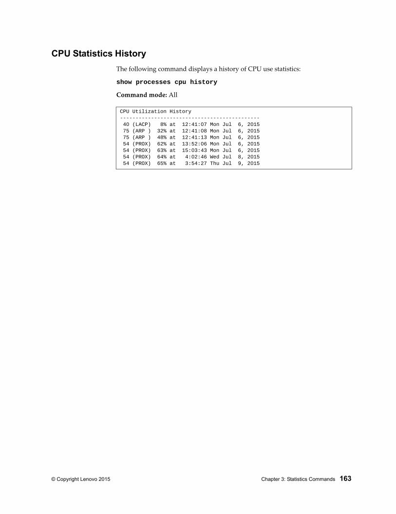
© Copyright Lenovo 2015 Chapter 3: Statistics Commands 163
CPU Statistics History
The following command displays a history of CPU use statistics:
show processes cpu history
Command mode: All
CPU Utilization History--------------------------------------------- 40 (LACP) 8% at 12:41:07 Mon Jul 6, 2015 75 (ARP ) 32% at 12:41:08 Mon Jul 6, 2015 75 (ARP ) 48% at 12:41:13 Mon Jul 6, 2015 54 (PROX) 62% at 13:52:06 Mon Jul 6, 2015 54 (PROX) 63% at 15:03:43 Mon Jul 6, 2015 54 (PROX) 64% at 4:02:46 Wed Jul 8, 2015 54 (PROX) 65% at 3:54:27 Thu Jul 9, 2015
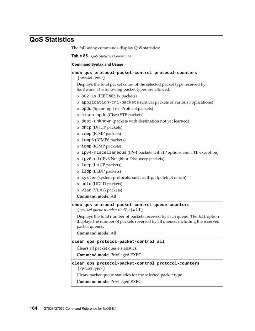
164 G7028/G7052 Command Reference for N/OS 8.1
QoS StatisticsThe following commands display QoS statistics:
Table 85. QoS Statistics Commands
Command Syntax and Usage
show qos protocol-packet-control protocol-counters [<packet type>]
Displays the total packet count of the selected packet type received by hardware. The following packet types are allowed: 802.1x (IEEE 802.1x packets) application-cri-packets (critical packets of various applications) bpdu (Spanning Tree Protocol packets) cisco-bpdu (Cisco STP packets) dest-unknown (packets with destination not yet learned) dhcp (DHCP packets) icmp (ICMP packets) icmp6 (ICMP6 packets) igmp (IGMP packets) ipv4-miscellaneous (IPv4 packets with IP options and TTL exception) ipv6-nd (IPv6 Neighbor Discovery packets) lacp (LACP packets) lldp (LLDP packets) system (system protocols, such as tftp, ftp, telnet or ssh) udld (UDLD packets) vlag (VLAG packets)Command mode: All
show qos protocol-packet-control queue-counters [<packet queue number (0-47)>|all]
Displays the total number of packets received by each queue. The all option displays the number of packets reveived by all queues, including the reserved packet queues.Command mode: All
clear qos protocol-packet-control all
Clears all packet queue statistics.Command mode: Privileged EXEC
clear qos protocol-packet-control protocol-counters [<packet type>]
Clears packet queue statistics for the selected packet type.Command mode: Privileged EXEC

© Copyright Lenovo 2015 Chapter 3: Statistics Commands 165
clear qos protocol-packet-control queue-counters [<packet queue number (0-47)>]
Clears packet queue statistics for the selected queue.Command mode: Privileged EXEC
Table 85. QoS Statistics Commands
Command Syntax and Usage
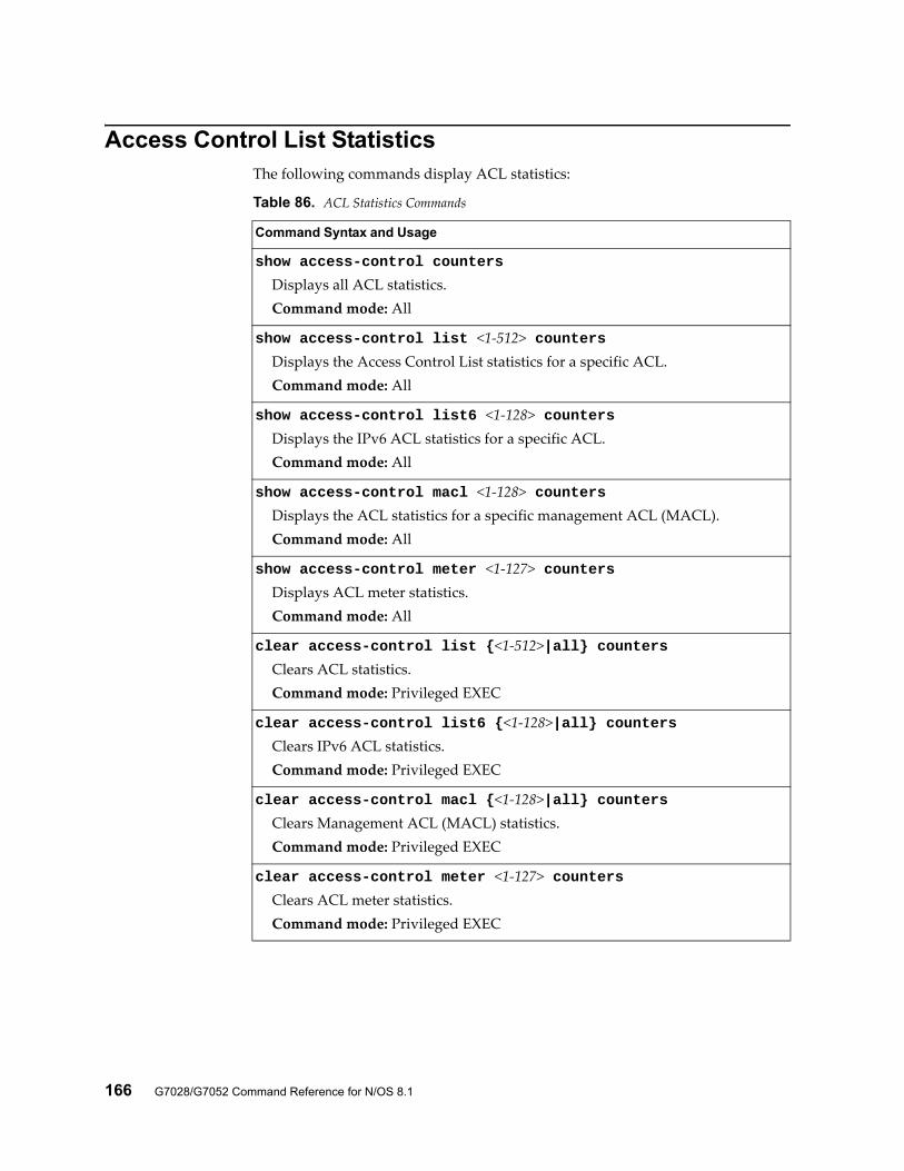
166 G7028/G7052 Command Reference for N/OS 8.1
Access Control List StatisticsThe following commands display ACL statistics:
Table 86. ACL Statistics Commands
Command Syntax and Usage
show access-control counters
Displays all ACL statistics.Command mode: All
show access-control list <1-512> countersDisplays the Access Control List statistics for a specific ACL.Command mode: All
show access-control list6 <1-128> countersDisplays the IPv6 ACL statistics for a specific ACL.Command mode: All
show access-control macl <1-128> countersDisplays the ACL statistics for a specific management ACL (MACL).Command mode: All
show access-control meter <1-127> countersDisplays ACL meter statistics.Command mode: All
clear access-control list {<1-512>|all} countersClears ACL statistics.Command mode: Privileged EXEC
clear access-control list6 {<1-128>|all} countersClears IPv6 ACL statistics.Command mode: Privileged EXEC
clear access-control macl {<1-128>|all} countersClears Management ACL (MACL) statistics.Command mode: Privileged EXEC
clear access-control meter <1-127> countersClears ACL meter statistics.Command mode: Privileged EXEC
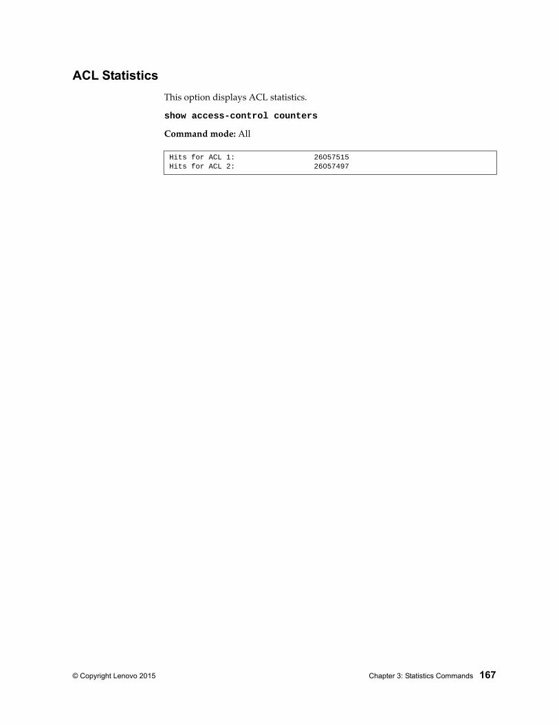
© Copyright Lenovo 2015 Chapter 3: Statistics Commands 167
ACL Statistics
This option displays ACL statistics.
show access-control counters
Command mode: All
Hits for ACL 1: 26057515Hits for ACL 2: 26057497
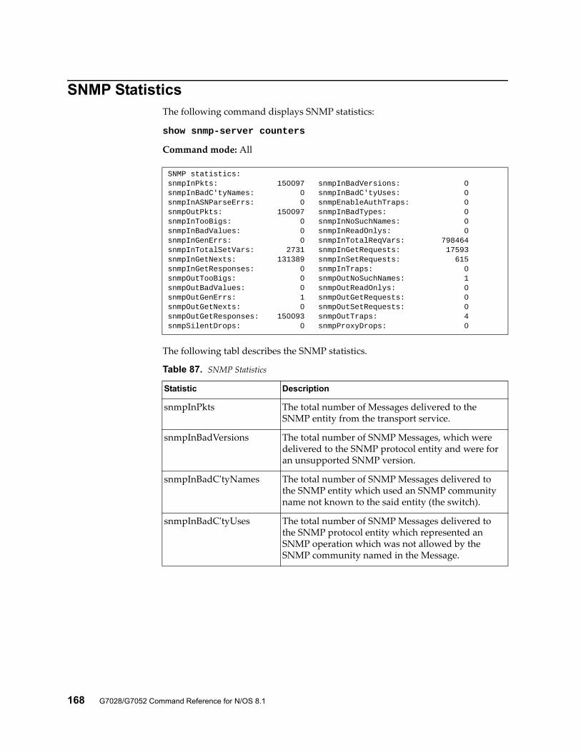
168 G7028/G7052 Command Reference for N/OS 8.1
SNMP StatisticsThe following command displays SNMP statistics:
show snmp-server counters
Command mode: All
The following tabl describes the SNMP statistics.
SNMP statistics:snmpInPkts: 150097 snmpInBadVersions: 0snmpInBadC'tyNames: 0 snmpInBadC'tyUses: 0snmpInASNParseErrs: 0 snmpEnableAuthTraps: 0snmpOutPkts: 150097 snmpInBadTypes: 0snmpInTooBigs: 0 snmpInNoSuchNames: 0snmpInBadValues: 0 snmpInReadOnlys: 0snmpInGenErrs: 0 snmpInTotalReqVars: 798464snmpInTotalSetVars: 2731 snmpInGetRequests: 17593snmpInGetNexts: 131389 snmpInSetRequests: 615snmpInGetResponses: 0 snmpInTraps: 0snmpOutTooBigs: 0 snmpOutNoSuchNames: 1snmpOutBadValues: 0 snmpOutReadOnlys: 0snmpOutGenErrs: 1 snmpOutGetRequests: 0snmpOutGetNexts: 0 snmpOutSetRequests: 0snmpOutGetResponses: 150093 snmpOutTraps: 4snmpSilentDrops: 0 snmpProxyDrops: 0
Table 87. SNMP Statistics
Statistic Description
snmpInPkts The total number of Messages delivered to the SNMP entity from the transport service.
snmpInBadVersions The total number of SNMP Messages, which were delivered to the SNMP protocol entity and were for an unsupported SNMP version.
snmpInBadC'tyNames The total number of SNMP Messages delivered to the SNMP entity which used an SNMP community name not known to the said entity (the switch).
snmpInBadC'tyUses The total number of SNMP Messages delivered to the SNMP protocol entity which represented an SNMP operation which was not allowed by the SNMP community named in the Message.
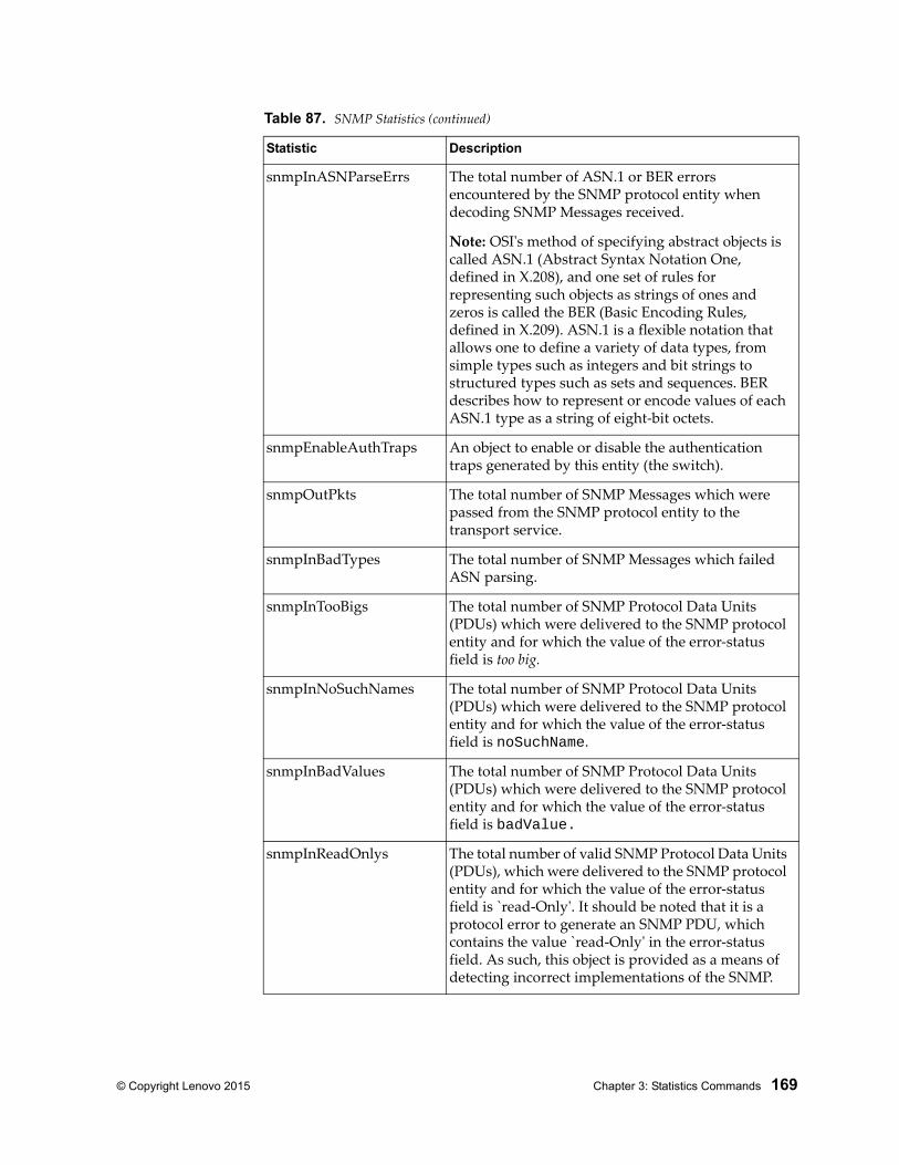
© Copyright Lenovo 2015 Chapter 3: Statistics Commands 169
snmpInASNParseErrs The total number of ASN.1 or BER errors encountered by the SNMP protocol entity when decoding SNMP Messages received.
Note: OSI's method of specifying abstract objects is called ASN.1 (Abstract Syntax Notation One, defined in X.208), and one set of rules for representing such objects as strings of ones and zeros is called the BER (Basic Encoding Rules, defined in X.209). ASN.1 is a flexible notation that allows one to define a variety of data types, from simple types such as integers and bit strings to structured types such as sets and sequences. BER describes how to represent or encode values of each ASN.1 type as a string of eight-bit octets.
snmpEnableAuthTraps An object to enable or disable the authentication traps generated by this entity (the switch).
snmpOutPkts The total number of SNMP Messages which were passed from the SNMP protocol entity to the transport service.
snmpInBadTypes The total number of SNMP Messages which failed ASN parsing.
snmpInTooBigs The total number of SNMP Protocol Data Units (PDUs) which were delivered to the SNMP protocol entity and for which the value of the error-status field is too big.
snmpInNoSuchNames The total number of SNMP Protocol Data Units (PDUs) which were delivered to the SNMP protocol entity and for which the value of the error-status field is noSuchName.
snmpInBadValues The total number of SNMP Protocol Data Units (PDUs) which were delivered to the SNMP protocol entity and for which the value of the error-status field is badValue.
snmpInReadOnlys The total number of valid SNMP Protocol Data Units (PDUs), which were delivered to the SNMP protocol entity and for which the value of the error-status field is `read-Only'. It should be noted that it is a protocol error to generate an SNMP PDU, which contains the value `read-Only' in the error-status field. As such, this object is provided as a means of detecting incorrect implementations of the SNMP.
Table 87. SNMP Statistics (continued)
Statistic Description
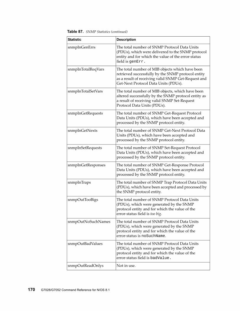
170 G7028/G7052 Command Reference for N/OS 8.1
snmpInGenErrs The total number of SNMP Protocol Data Units (PDUs), which were delivered to the SNMP protocol entity and for which the value of the error-status field is genErr.
snmpInTotalReqVars The total number of MIB objects which have been retrieved successfully by the SNMP protocol entity as a result of receiving valid SNMP Get-Request and Get-Next Protocol Data Units (PDUs).
snmpInTotalSetVars The total number of MIB objects, which have been altered successfully by the SNMP protocol entity as a result of receiving valid SNMP Set-Request Protocol Data Units (PDUs).
snmpInGetRequests The total number of SNMP Get-Request Protocol Data Units (PDUs), which have been accepted and processed by the SNMP protocol entity.
snmpInGetNexts The total number of SNMP Get-Next Protocol Data Units (PDUs), which have been accepted and processed by the SNMP protocol entity.
snmpInSetRequests The total number of SNMP Set-Request Protocol Data Units (PDUs), which have been accepted and processed by the SNMP protocol entity.
snmpInGetResponses The total number of SNMP Get-Response Protocol Data Units (PDUs), which have been accepted and processed by the SNMP protocol entity.
snmpInTraps The total number of SNMP Trap Protocol Data Units (PDUs), which have been accepted and processed by the SNMP protocol entity.
snmpOutTooBigs The total number of SNMP Protocol Data Units (PDUs), which were generated by the SNMP protocol entity and for which the value of the error-status field is too big.
snmpOutNoSuchNames The total number of SNMP Protocol Data Units (PDUs), which were generated by the SNMP protocol entity and for which the value of the error-status is noSuchName.
snmpOutBadValues The total number of SNMP Protocol Data Units (PDUs), which were generated by the SNMP protocol entity and for which the value of the error-status field is badValue.
snmpOutReadOnlys Not in use.
Table 87. SNMP Statistics (continued)
Statistic Description
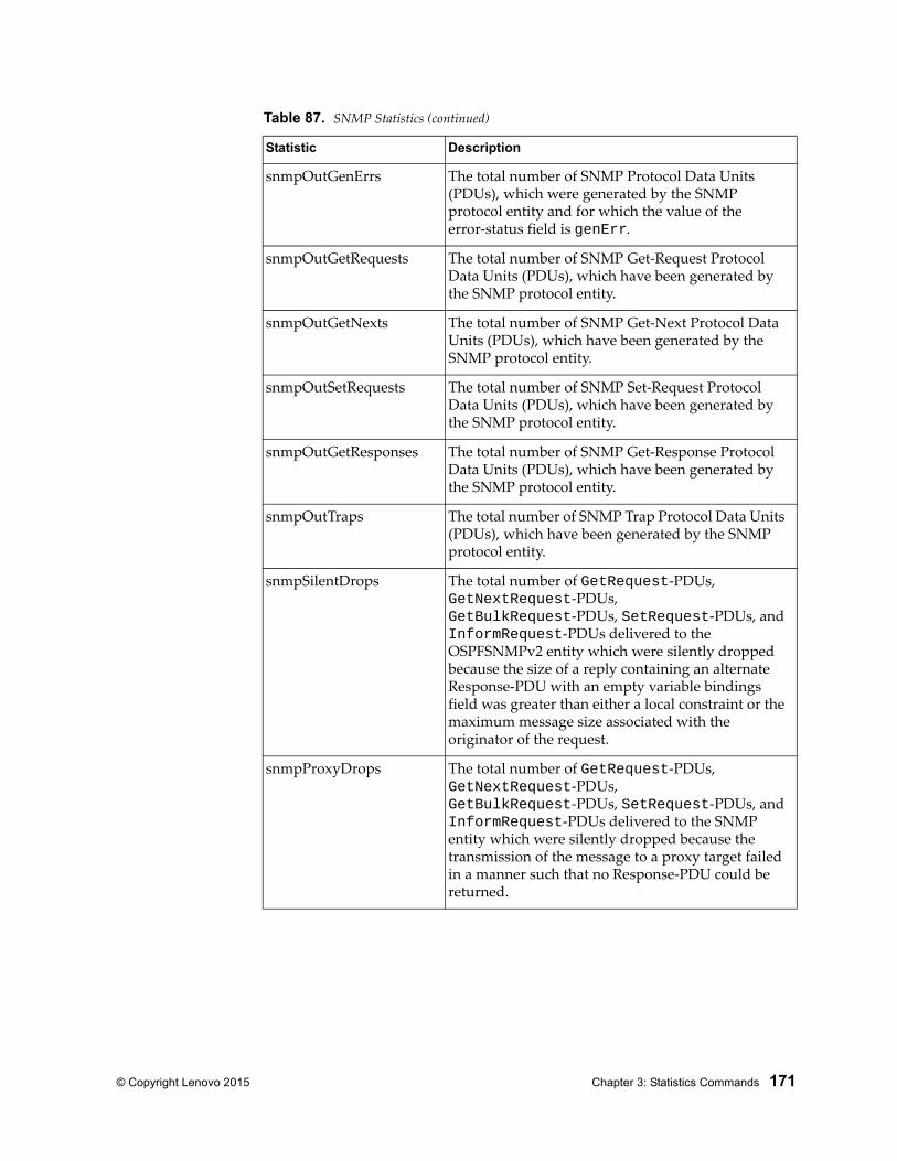
© Copyright Lenovo 2015 Chapter 3: Statistics Commands 171
snmpOutGenErrs The total number of SNMP Protocol Data Units (PDUs), which were generated by the SNMP protocol entity and for which the value of the error-status field is genErr.
snmpOutGetRequests The total number of SNMP Get-Request Protocol Data Units (PDUs), which have been generated by the SNMP protocol entity.
snmpOutGetNexts The total number of SNMP Get-Next Protocol Data Units (PDUs), which have been generated by the SNMP protocol entity.
snmpOutSetRequests The total number of SNMP Set-Request Protocol Data Units (PDUs), which have been generated by the SNMP protocol entity.
snmpOutGetResponses The total number of SNMP Get-Response Protocol Data Units (PDUs), which have been generated by the SNMP protocol entity.
snmpOutTraps The total number of SNMP Trap Protocol Data Units (PDUs), which have been generated by the SNMP protocol entity.
snmpSilentDrops The total number of GetRequest-PDUs, GetNextRequest-PDUs, GetBulkRequest-PDUs, SetRequest-PDUs, and InformRequest-PDUs delivered to the OSPFSNMPv2 entity which were silently dropped because the size of a reply containing an alternate Response-PDU with an empty variable bindings field was greater than either a local constraint or the maximum message size associated with the originator of the request.
snmpProxyDrops The total number of GetRequest-PDUs, GetNextRequest-PDUs, GetBulkRequest-PDUs, SetRequest-PDUs, and InformRequest-PDUs delivered to the SNMP entity which were silently dropped because the transmission of the message to a proxy target failed in a manner such that no Response-PDU could be returned.
Table 87. SNMP Statistics (continued)
Statistic Description
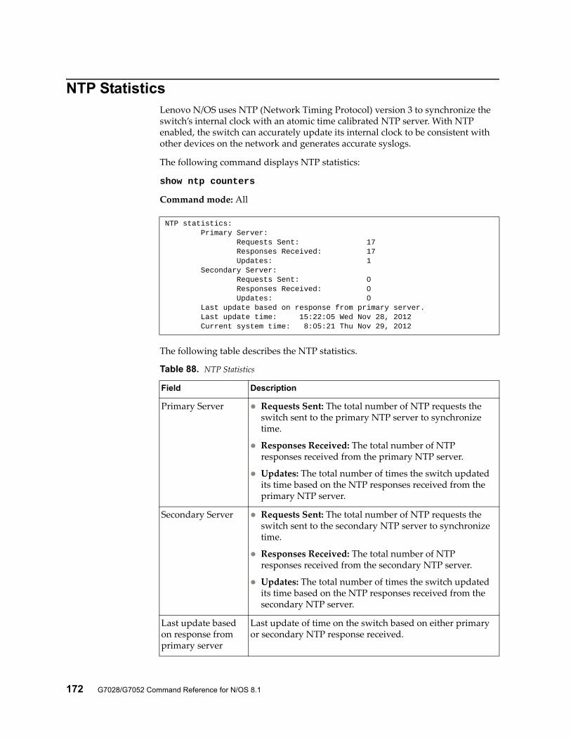
172 G7028/G7052 Command Reference for N/OS 8.1
NTP StatisticsLenovo N/OS uses NTP (Network Timing Protocol) version 3 to synchronize the switch’s internal clock with an atomic time calibrated NTP server. With NTP enabled, the switch can accurately update its internal clock to be consistent with other devices on the network and generates accurate syslogs.
The following command displays NTP statistics:
show ntp counters
Command mode: All
The following table describes the NTP statistics.
NTP statistics: Primary Server: Requests Sent: 17 Responses Received: 17 Updates: 1 Secondary Server: Requests Sent: 0 Responses Received: 0 Updates: 0 Last update based on response from primary server. Last update time: 15:22:05 Wed Nov 28, 2012 Current system time: 8:05:21 Thu Nov 29, 2012
Table 88. NTP Statistics
Field Description
Primary Server Requests Sent: The total number of NTP requests the switch sent to the primary NTP server to synchronize time.
Responses Received: The total number of NTP responses received from the primary NTP server.
Updates: The total number of times the switch updated its time based on the NTP responses received from the primary NTP server.
Secondary Server Requests Sent: The total number of NTP requests the switch sent to the secondary NTP server to synchronize time.
Responses Received: The total number of NTP responses received from the secondary NTP server.
Updates: The total number of times the switch updated its time based on the NTP responses received from the secondary NTP server.
Last update based on response from primary server
Last update of time on the switch based on either primary or secondary NTP response received.
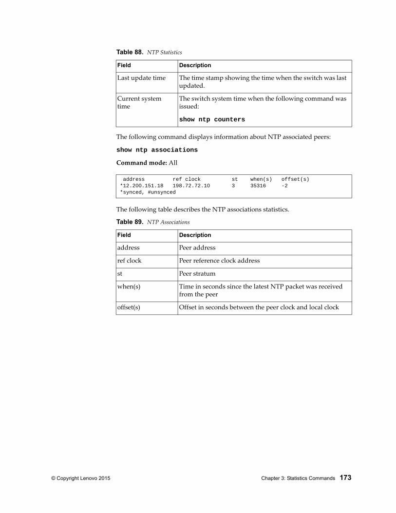
© Copyright Lenovo 2015 Chapter 3: Statistics Commands 173
The following command displays information about NTP associated peers:
show ntp associations
Command mode: All
The following table describes the NTP associations statistics.
Last update time The time stamp showing the time when the switch was last updated.
Current system time
The switch system time when the following command was issued:
show ntp counters
address ref clock st when(s) offset(s)*12.200.151.18 198.72.72.10 3 35316 -2*synced, #unsynced
Table 89. NTP Associations
Field Description
address Peer address
ref clock Peer reference clock address
st Peer stratum
when(s) Time in seconds since the latest NTP packet was received from the peer
offset(s) Offset in seconds between the peer clock and local clock
Table 88. NTP Statistics
Field Description
174 G7028/G7052 Command Reference for N/OS 8.1
Statistics DumpThe following command dumps switch statistics:
show counters
Use the dump command to dump all switch statistics (40K or more, depending on your configuration). This data can be used to tune or debug switch performance.
If you want to capture dump data to a file, set your communication software on your workstation to capture session data prior to issuing the dump command.
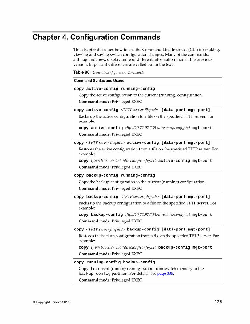
© Copyright Lenovo 2015 175
Chapter 4. Configuration Commands
This chapter discusses how to use the Command Line Interface (CLI) for making, viewing and saving switch configuration changes. Many of the commands, although not new, display more or different information than in the previous version. Important differences are called out in the text.
Table 90. General Configuration Commands
Command Syntax and Usage
copy active-config running-config
Copy the active configuration to the current (running) configuration.Command mode: Privileged EXEC
copy active-config <TFTP server filepath> [data-port|mgt-port]Backs up the active configuration to a file on the specified TFTP server. For example:copy active-config tftp://10.72.97.135:/directory/config.txt mgt-portCommand mode: Privileged EXEC
copy <TFTP server filepath> active-config [data-port|mgt-port]Restores the active configuration from a file on the specified TFTP server. For example:copy tftp://10.72.97.135:/directory/config.txt active-config mgt-portCommand mode: Privileged EXEC
copy backup-config running-config
Copy the backup configuration to the current (running) configuration.Command mode: Privileged EXEC
copy backup-config <TFTP server filepath> [data-port|mgt-port]Backs up the backup configuration to a file on the specified TFTP server. For example:copy backup-config tftp://10.72.97.135:/directory/config.txt mgt-portCommand mode: Privileged EXEC
copy <TFTP server filepath> backup-config [data-port|mgt-port]Restores the backup configuration from a file on the specified TFTP server. For example:copy tftp://10.72.97.135:/directory/config.txt backup-config mgt-portCommand mode: Privileged EXEC
copy running-config backup-config
Copy the current (running) configuration from switch memory to the backup-config partition. For details, see page 335.Command mode: Privileged EXEC
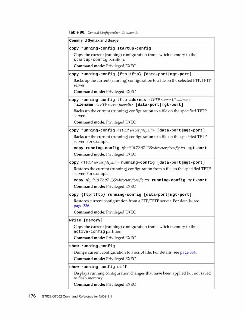
176 G7028/G7052 Command Reference for N/OS 8.1
copy running-config startup-config
Copy the current (running) configuration from switch memory to the startup-config partition.Command mode: Privileged EXEC
copy running-config {ftp|tftp} [data-port|mgt-port]
Backs up the current (running) configuration to a file on the selected FTP/TFTP server.Command mode: Privileged EXEC
copy running-config tftp address <TFTP server IP address> filename <TFTP server filepath> [data-port|mgt-port]
Backs up the current (running) configuration to a file on the specified TFTP server.Command mode: Privileged EXEC
copy running-config <TFTP server filepath> [data-port|mgt-port]Backs up the current (running) configuration to a file on the specified TFTP server. For example:copy running-config tftp://10.72.97.135:/directory/config.txt mgt-portCommand mode: Privileged EXEC
copy <TFTP server filepath> running-config [data-port|mgt-port]Restores the current (running) configuration from a file on the specified TFTP server. For example:copy tftp://10.72.97.135:/directory/config.txt running-config mgt-portCommand mode: Privileged EXEC
copy {ftp|tftp} running-config [data-port|mgt-port]
Restores current configuration from a FTP/TFTP server. For details, see page 336.Command mode: Privileged EXEC
write [memory]
Copy the current (running) configuration from switch memory to the active-config partition.Command mode: Privileged EXEC
show running-config
Dumps current configuration to a script file. For details, see page 334.Command mode: Privileged EXEC
show running-config diff
Displays running configuration changes that have been applied but not saved to flash memory.Command mode: Privileged EXEC
Table 90. General Configuration Commands
Command Syntax and Usage
© Copyright Lenovo 2015 Chapter 4: Configuration Commands 177
Viewing and Saving ChangesAs you use the configuration commands to set switch parameters, the changes you make take effect immediately. You do not need to apply them. Configuration changes are lost the next time the switch boots, unless you save the changes.
You can view all running configuration changes that have been applied but not saved to flash memory using the show running-config diff command in Privileged EXEC mode.Note: Some operations can override the settings of the Configuration commands. Therefore, settings you view using the Configuration commands (for example, port status) might differ from run-time information that you view using the Information commands. The Information commands display current run-time information of switch parameters.
Saving the Configuration
You must save configuration settings to flash memory, so the G7028/G7052 reloads the settings after a reboot.Note: If you do not save the changes, they will be lost the next time the system is rebooted.
To save the new configuration, enter the following command:
or:
Note: The write command doesn’t prompt the user for confirmation.
When you save configuration changes, the changes are saved to the active configuration block. For instructions on selecting the configuration to run at the next system reboot, see “Selecting a Configuration Block” on page 348.
RS G7052# copy running-config startup-config
RS G7052# write
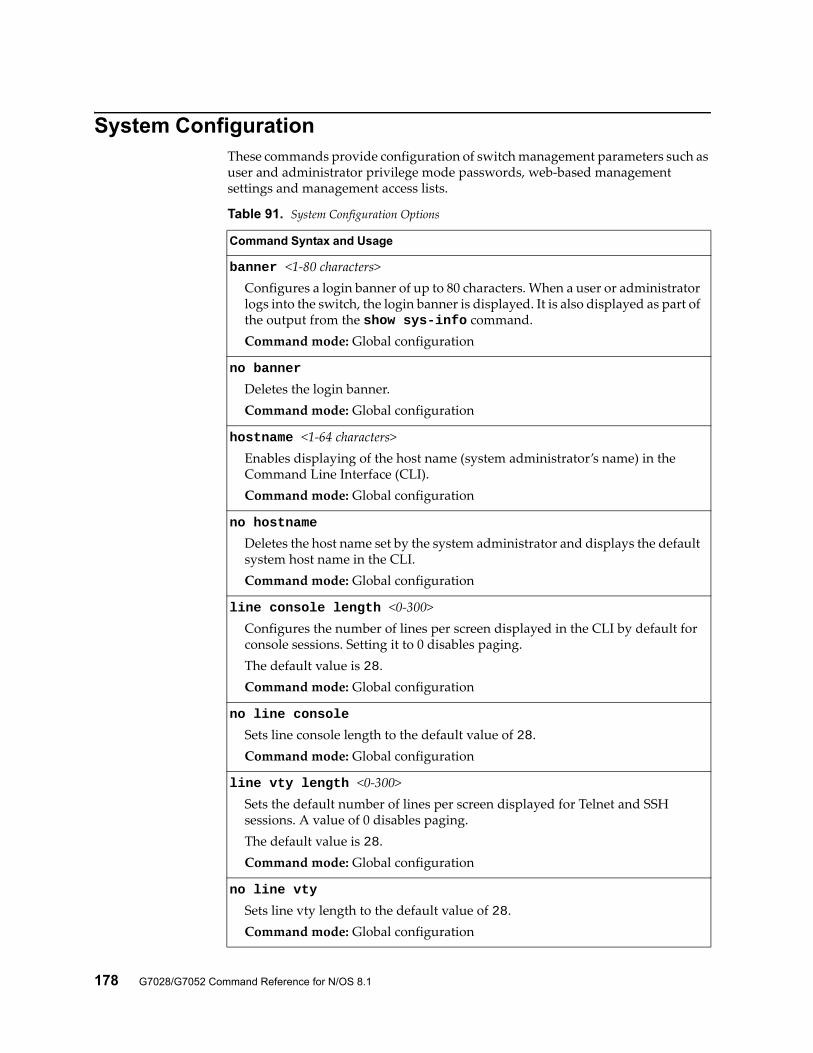
178 G7028/G7052 Command Reference for N/OS 8.1
System ConfigurationThese commands provide configuration of switch management parameters such as user and administrator privilege mode passwords, web-based management settings and management access lists.
Table 91. System Configuration Options
Command Syntax and Usage
banner <1-80 characters>Configures a login banner of up to 80 characters. When a user or administrator logs into the switch, the login banner is displayed. It is also displayed as part of the output from the show sys-info command.Command mode: Global configuration
no banner
Deletes the login banner.Command mode: Global configuration
hostname <1-64 characters>Enables displaying of the host name (system administrator’s name) in the Command Line Interface (CLI).Command mode: Global configuration
no hostname
Deletes the host name set by the system administrator and displays the default system host name in the CLI.Command mode: Global configuration
line console length <0-300>Configures the number of lines per screen displayed in the CLI by default for console sessions. Setting it to 0 disables paging.The default value is 28.Command mode: Global configuration
no line console
Sets line console length to the default value of 28.Command mode: Global configuration
line vty length <0-300>Sets the default number of lines per screen displayed for Telnet and SSH sessions. A value of 0 disables paging.The default value is 28.Command mode: Global configuration
no line vty
Sets line vty length to the default value of 28.Command mode: Global configuration
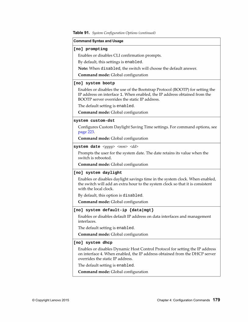
© Copyright Lenovo 2015 Chapter 4: Configuration Commands 179
[no] prompting
Enables or disables CLI confirmation prompts.By default, this settings is enabled.Note: When disabled, the switch will choose the default answer.Command mode: Global configuration
[no] system bootp
Enables or disables the use of the Bootstrap Protocol (BOOTP) for setting the IP address on interface 1. When enabled, the IP address obtained from the BOOTP server overrides the static IP address.The default setting is enabled.Command mode: Global configuration
system custom-dst
Configures Custom Daylight Saving Time settings. For command options, see page 223.Command mode: Global configuration
system date <yyyy> <mm> <dd>Prompts the user for the system date. The date retains its value when the switch is rebooted.Command mode: Global configuration
[no] system daylight
Enables or disables daylight savings time in the system clock. When enabled, the switch will add an extra hour to the system clock so that it is consistent with the local clock.By default, this option is disabled.Command mode: Global configuration
[no] system default-ip {data|mgt}
Enables or disables default IP address on data interfaces and management interfaces.The default setting is enabled.Command mode: Global configuration
[no] system dhcp
Enables or disables Dynamic Host Control Protocol for setting the IP address on interface 4. When enabled, the IP address obtained from the DHCP server overrides the static IP address.The default setting is enabled.Command mode: Global configuration
Table 91. System Configuration Options (continued)
Command Syntax and Usage
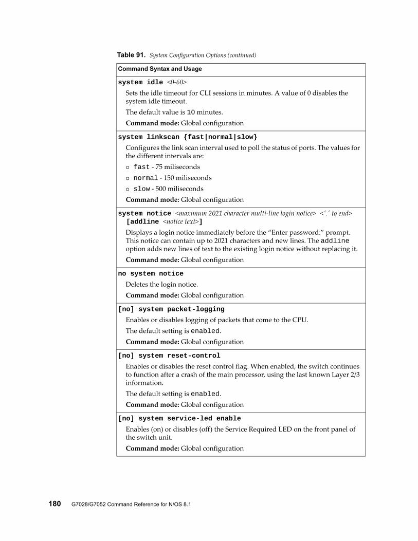
180 G7028/G7052 Command Reference for N/OS 8.1
system idle <0-60>Sets the idle timeout for CLI sessions in minutes. A value of 0 disables the system idle timeout.The default value is 10 minutes.Command mode: Global configuration
system linkscan {fast|normal|slow}
Configures the link scan interval used to poll the status of ports. The values for the different intervals are: fast - 75 miliseconds normal - 150 miliseconds slow - 500 milisecondsCommand mode: Global configuration
system notice <maximum 2021 character multi-line login notice> <'.' to end> [addline <notice text>]
Displays a login notice immediately before the “Enter password:” prompt. This notice can contain up to 2021 characters and new lines. The addline option adds new lines of text to the existing login notice without replacing it.Command mode: Global configuration
no system notice
Deletes the login notice.Command mode: Global configuration
[no] system packet-logging
Enables or disables logging of packets that come to the CPU.The default setting is enabled.Command mode: Global configuration
[no] system reset-control
Enables or disables the reset control flag. When enabled, the switch continues to function after a crash of the main processor, using the last known Layer 2/3 information.The default setting is enabled.Command mode: Global configuration
[no] system service-led enable
Enables (on) or disables (off) the Service Required LED on the front panel of the switch unit.Command mode: Global configuration
Table 91. System Configuration Options (continued)
Command Syntax and Usage
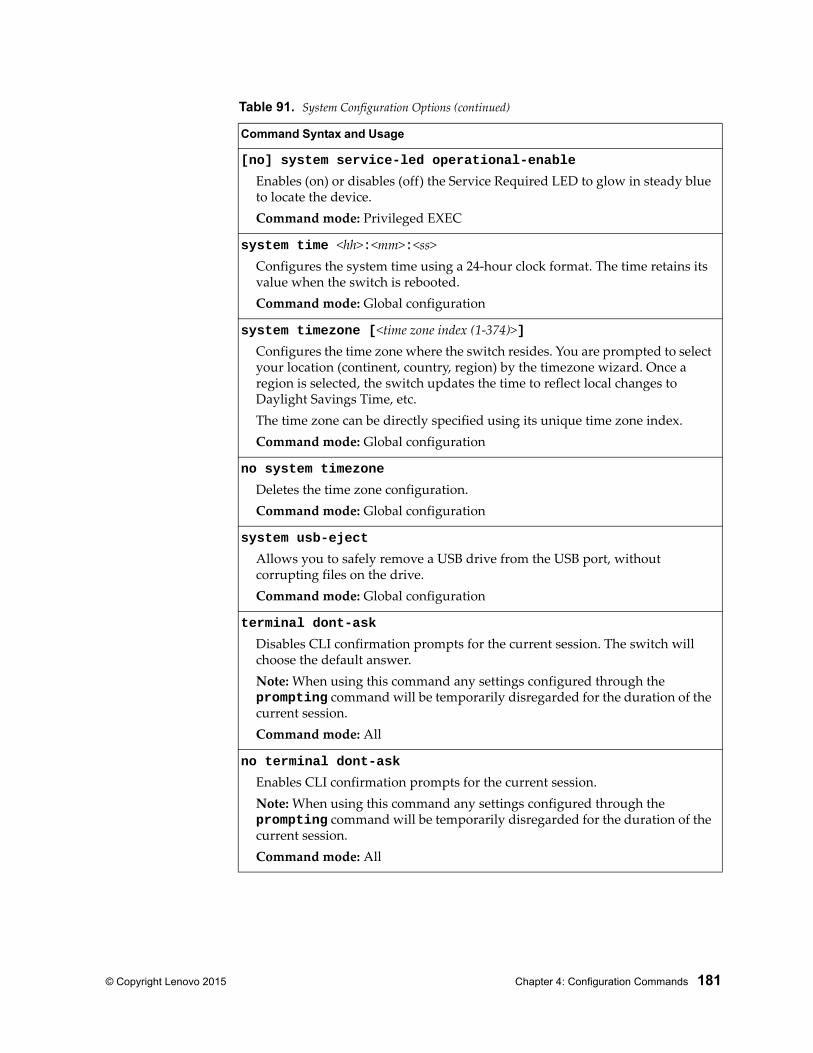
© Copyright Lenovo 2015 Chapter 4: Configuration Commands 181
[no] system service-led operational-enable
Enables (on) or disables (off) the Service Required LED to glow in steady blue to locate the device.Command mode: Privileged EXEC
system time <hh>:<mm>:<ss>Configures the system time using a 24-hour clock format. The time retains its value when the switch is rebooted.Command mode: Global configuration
system timezone [<time zone index (1-374)>]Configures the time zone where the switch resides. You are prompted to select your location (continent, country, region) by the timezone wizard. Once a region is selected, the switch updates the time to reflect local changes to Daylight Savings Time, etc.The time zone can be directly specified using its unique time zone index.Command mode: Global configuration
no system timezone
Deletes the time zone configuration.Command mode: Global configuration
system usb-eject
Allows you to safely remove a USB drive from the USB port, without corrupting files on the drive.Command mode: Global configuration
terminal dont-ask
Disables CLI confirmation prompts for the current session. The switch will choose the default answer.Note: When using this command any settings configured through the prompting command will be temporarily disregarded for the duration of the current session.Command mode: All
no terminal dont-ask
Enables CLI confirmation prompts for the current session.Note: When using this command any settings configured through the prompting command will be temporarily disregarded for the duration of the current session.Command mode: All
Table 91. System Configuration Options (continued)
Command Syntax and Usage
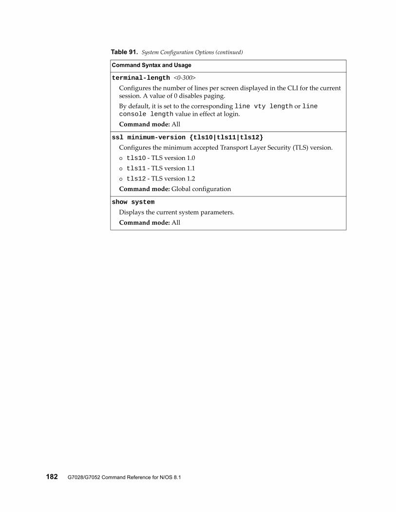
182 G7028/G7052 Command Reference for N/OS 8.1
terminal-length <0-300>Configures the number of lines per screen displayed in the CLI for the current session. A value of 0 disables paging.By default, it is set to the corresponding line vty length or line console length value in effect at login.Command mode: All
ssl minimum-version {tls10|tls11|tls12}
Configures the minimum accepted Transport Layer Security (TLS) version. tls10 - TLS version 1.0 tls11 - TLS version 1.1 tls12 - TLS version 1.2Command mode: Global configuration
show system
Displays the current system parameters.Command mode: All
Table 91. System Configuration Options (continued)
Command Syntax and Usage
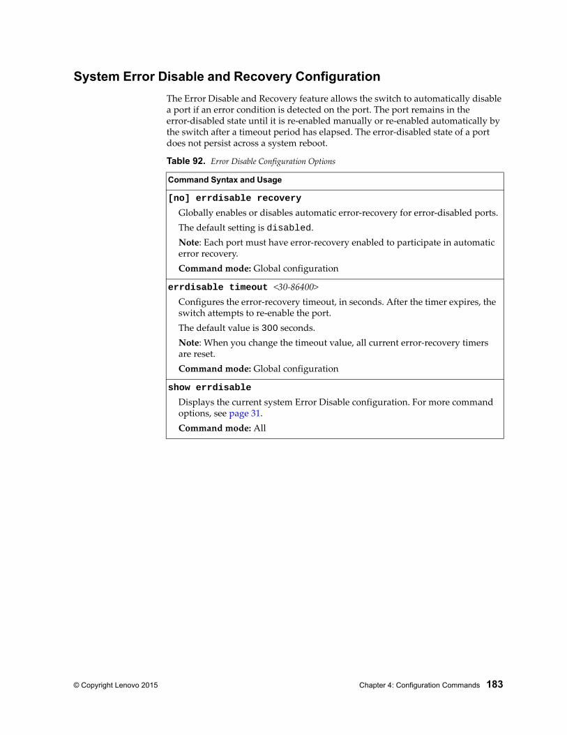
© Copyright Lenovo 2015 Chapter 4: Configuration Commands 183
System Error Disable and Recovery Configuration
The Error Disable and Recovery feature allows the switch to automatically disable a port if an error condition is detected on the port. The port remains in the error-disabled state until it is re-enabled manually or re-enabled automatically by the switch after a timeout period has elapsed. The error-disabled state of a port does not persist across a system reboot.
Table 92. Error Disable Configuration Options
Command Syntax and Usage
[no] errdisable recovery
Globally enables or disables automatic error-recovery for error-disabled ports.The default setting is disabled.Note: Each port must have error-recovery enabled to participate in automatic error recovery.Command mode: Global configuration
errdisable timeout <30-86400>Configures the error-recovery timeout, in seconds. After the timer expires, the switch attempts to re-enable the port.The default value is 300 seconds.Note: When you change the timeout value, all current error-recovery timers are reset.Command mode: Global configuration
show errdisable
Displays the current system Error Disable configuration. For more command options, see page 31.Command mode: All
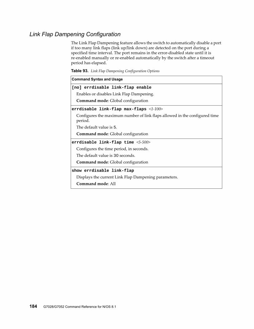
184 G7028/G7052 Command Reference for N/OS 8.1
Link Flap Dampening ConfigurationThe Link Flap Dampening feature allows the switch to automatically disable a port if too many link flaps (link up/link down) are detected on the port during a specified time interval. The port remains in the error-disabled state until it is re-enabled manually or re-enabled automatically by the switch after a timeout period has elapsed.
Table 93. Link Flap Dampening Configuration Options
Command Syntax and Usage
[no] errdisable link-flap enable
Enables or disables Link Flap Dampening.Command mode: Global configuration
errdisable link-flap max-flaps <1-100>Configures the maximum number of link flaps allowed in the configured time period.The default value is 5.Command mode: Global configuration
errdisable link-flap time <5-500>Configures the time period, in seconds.The default value is 30 seconds.Command mode: Global configuration
show errdisable link-flap
Displays the current Link Flap Dampening parameters.Command mode: All
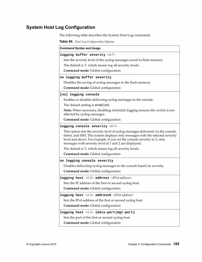
© Copyright Lenovo 2015 Chapter 4: Configuration Commands 185
System Host Log Configuration
The following table describes the System Host Log commands.
Table 94. Host Log Configuration Options
Command Syntax and Usage
logging buffer severity <0-7>Sets the severity level of the syslog messages saved to flash memory.The default is 7, which means log all severity levels.Command mode: Global configuration
no logging buffer severity
Disables the saving of syslog messages to the flash memory.Command mode: Global configuration
[no] logging console
Enables or disables delivering syslog messages to the console.The default setting is enabled.Note: When necessary, disabling console logging ensures the switch is not affected by syslog messages.Command mode: Global configuration
logging console severity <0-7>This option sets the severity level of syslog messages delivered via the console, telnet, and SSH. The system displays only messages with the selected severity level and above. For example, if you set the console severity to 2, only messages with severity level of 1 and 2 are displayed.The default is 7, which means log all severity levels.Command mode: Global configuration
no logging console severity
Disables delivering syslog messages to the console based on severity.Command mode: Global configuration
logging host <1-2> address <IPv4 address>Sets the IP address of the first or second syslog host.Command mode: Global configuration
logging host <1-2> address6 <IPv6 address>Sets the IPv6 address of the first or second syslog host.Command mode: Global configuration
logging host <1-2> {data-port|mgt-port}Sets the port of the first or second syslog host.Command mode: Global configuration
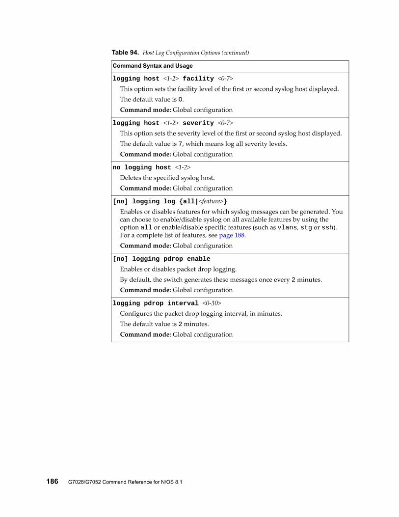
186 G7028/G7052 Command Reference for N/OS 8.1
logging host <1-2> facility <0-7>This option sets the facility level of the first or second syslog host displayed.The default value is 0.Command mode: Global configuration
logging host <1-2> severity <0-7>This option sets the severity level of the first or second syslog host displayed.The default value is 7, which means log all severity levels.Command mode: Global configuration
no logging host <1-2>Deletes the specified syslog host.Command mode: Global configuration
[no] logging log {all|<feature>}Enables or disables features for which syslog messages can be generated. You can choose to enable/disable syslog on all available features by using the option all or enable/disable specific features (such as vlans, stg or ssh). For a complete list of features, see page 188.Command mode: Global configuration
[no] logging pdrop enable
Enables or disables packet drop logging.By default, the switch generates these messages once every 2 minutes.Command mode: Global configuration
logging pdrop interval <0-30>Configures the packet drop logging interval, in minutes.The default value is 2 minutes.Command mode: Global configuration
Table 94. Host Log Configuration Options (continued)
Command Syntax and Usage
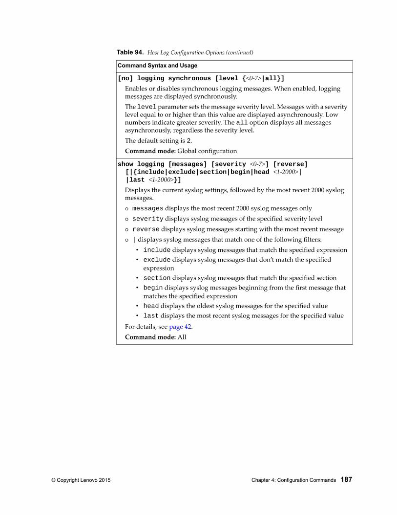
© Copyright Lenovo 2015 Chapter 4: Configuration Commands 187
[no] logging synchronous [level {<0-7>|all}]Enables or disables synchronous logging messages. When enabled, logging messages are displayed synchronously.The level parameter sets the message severity level. Messages with a severity level equal to or higher than this value are displayed asynchronously. Low numbers indicate greater severity. The all option displays all messages asynchronously, regardless the severity level.The default setting is 2.Command mode: Global configuration
show logging [messages] [severity <0-7>] [reverse] [|{include|exclude|section|begin|head <1-2000>| |last <1-2000>}]
Displays the current syslog settings, followed by the most recent 2000 syslog messages. messages displays the most recent 2000 syslog messages only severity displays syslog messages of the specified severity level reverse displays syslog messages starting with the most recent message | displays syslog messages that match one of the following filters:
• include displays syslog messages that match the specified expression• exclude displays syslog messages that don’t match the specified
expression• section displays syslog messages that match the specified section• begin displays syslog messages beginning from the first message that
matches the specified expression• head displays the oldest syslog messages for the specified value• last displays the most recent syslog messages for the specified value
For details, see page 42.Command mode: All
Table 94. Host Log Configuration Options (continued)
Command Syntax and Usage
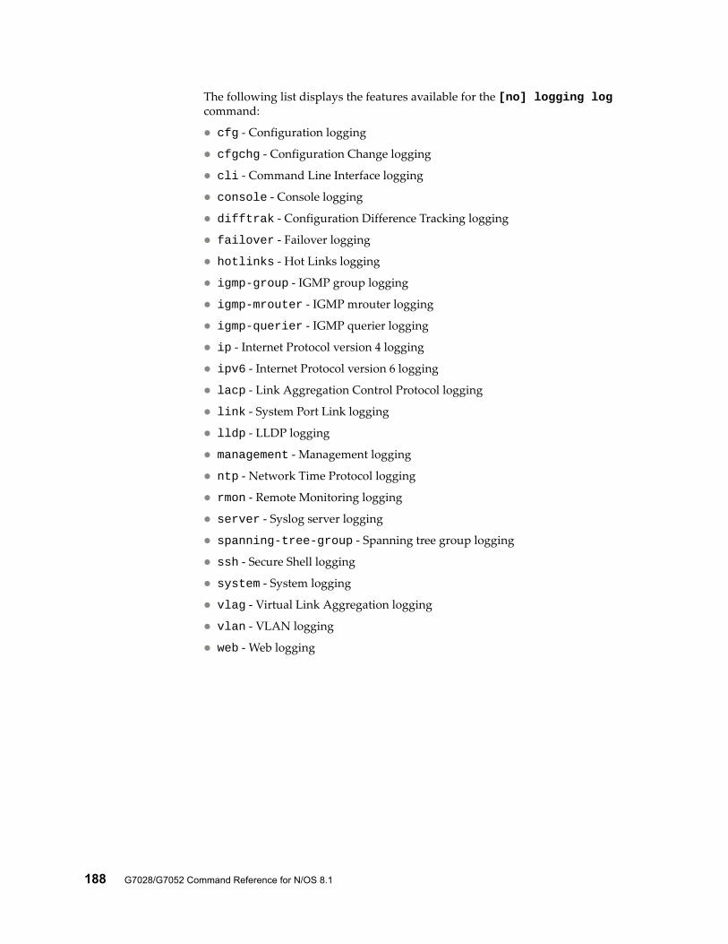
188 G7028/G7052 Command Reference for N/OS 8.1
The following list displays the features available for the [no] logging log command:
cfg - Configuration logging
cfgchg - Configuration Change logging
cli - Command Line Interface logging
console - Console logging
difftrak - Configuration Difference Tracking logging
failover - Failover logging
hotlinks - Hot Links logging
igmp-group - IGMP group logging
igmp-mrouter - IGMP mrouter logging
igmp-querier - IGMP querier logging
ip - Internet Protocol version 4 logging
ipv6 - Internet Protocol version 6 logging
lacp - Link Aggregation Control Protocol logging
link - System Port Link logging
lldp - LLDP logging
management - Management logging
ntp - Network Time Protocol logging
rmon - Remote Monitoring logging
server - Syslog server logging
spanning-tree-group - Spanning tree group logging
ssh - Secure Shell logging
system - System logging
vlag - Virtual Link Aggregation logging
vlan - VLAN logging
web - Web logging
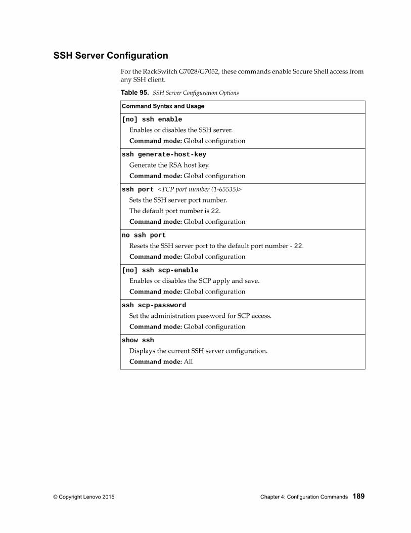
© Copyright Lenovo 2015 Chapter 4: Configuration Commands 189
SSH Server Configuration
For the RackSwitch G7028/G7052, these commands enable Secure Shell access from any SSH client.
Table 95. SSH Server Configuration Options
Command Syntax and Usage
[no] ssh enable
Enables or disables the SSH server.Command mode: Global configuration
ssh generate-host-key
Generate the RSA host key.Command mode: Global configuration
ssh port <TCP port number (1-65535)>Sets the SSH server port number.The default port number is 22.Command mode: Global configuration
no ssh port
Resets the SSH server port to the default port number - 22.Command mode: Global configuration
[no] ssh scp-enable
Enables or disables the SCP apply and save.Command mode: Global configuration
ssh scp-password
Set the administration password for SCP access.Command mode: Global configuration
show ssh
Displays the current SSH server configuration.Command mode: All
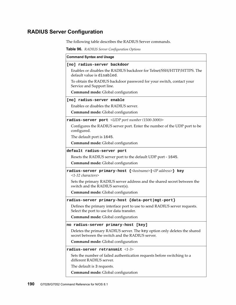
190 G7028/G7052 Command Reference for N/OS 8.1
RADIUS Server Configuration
The following table describes the RADIUS Server commands.
Table 96. RADIUS Server Configuration Options
Command Syntax and Usage
[no] radius-server backdoor
Enables or disables the RADIUS backdoor for Telnet/SSH/HTTP/HTTPS. The default value is disabled.To obtain the RADIUS backdoor password for your switch, contact your Service and Support line.Command mode: Global configuration
[no] radius-server enable
Enables or disables the RADIUS server.Command mode: Global configuration
radius-server port <UDP port number (1500-3000)>Configures the RADIUS server port. Enter the number of the UDP port to be configured.The default port is 1645.Command mode: Global configuration
default radius-server port
Resets the RADIUS server port to the default UDP port - 1645.Command mode: Global configuration
radius-server primary-host {<hostname>|<IP address>} key <1-32 characters>
Sets the primary RADIUS server address and the shared secret between the switch and the RADIUS server(s).Command mode: Global configuration
radius-server primary-host {data-port|mgt-port}
Defines the primary interface port to use to send RADIUS server requests. Select the port to use for data transfer.Command mode: Global configuration
no radius-server primary-host [key]
Deletes the primary RADIUS server. The key option only deletes the shared secret between the switch and the RADIUS server.Command mode: Global configuration
radius-server retransmit <1-3>Sets the number of failed authentication requests before switching to a different RADIUS server.The default is 3 requests.Command mode: Global configuration
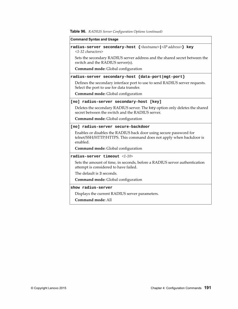
© Copyright Lenovo 2015 Chapter 4: Configuration Commands 191
radius-server secondary-host {<hostname>|<IP address>} key <1-32 characters>
Sets the secondary RADIUS server address and the shared secret between the switch and the RADIUS server(s).Command mode: Global configuration
radius-server secondary-host {data-port|mgt-port}
Defines the secondary interface port to use to send RADIUS server requests. Select the port to use for data transfer.Command mode: Global configuration
[no] radius-server secondary-host [key]
Deletes the secondary RADIUS server. The key option only deletes the shared secret between the switch and the RADIUS server.Command mode: Global configuration
[no] radius-server secure-backdoor
Enables or disables the RADIUS back door using secure password for telnet/SSH/HTTP/HTTPS. This command does not apply when backdoor is enabled.Command mode: Global configuration
radius-server timeout <1-10>Sets the amount of time, in seconds, before a RADIUS server authentication attempt is considered to have failed.The default is 3 seconds.Command mode: Global configuration
show radius-server
Displays the current RADIUS server parameters.Command mode: All
Table 96. RADIUS Server Configuration Options (continued)
Command Syntax and Usage
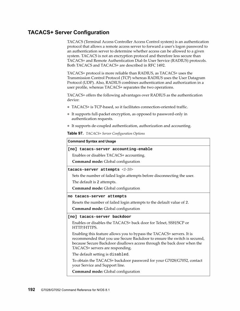
192 G7028/G7052 Command Reference for N/OS 8.1
TACACS+ Server Configuration
TACACS (Terminal Access Controller Access Control system) is an authentication protocol that allows a remote access server to forward a user's logon password to an authentication server to determine whether access can be allowed to a given system. TACACS is not an encryption protocol and therefore less secure than TACACS+ and Remote Authentication Dial-In User Service (RADIUS) protocols. Both TACACS and TACACS+ are described in RFC 1492.
TACACS+ protocol is more reliable than RADIUS, as TACACS+ uses the Transmission Control Protocol (TCP) whereas RADIUS uses the User Datagram Protocol (UDP). Also, RADIUS combines authentication and authorization in a user profile, whereas TACACS+ separates the two operations.
TACACS+ offers the following advantages over RADIUS as the authentication device:
TACACS+ is TCP-based, so it facilitates connection-oriented traffic.
It supports full-packet encryption, as opposed to password-only in authentication requests.
It supports de-coupled authentication, authorization and accounting.
Table 97. TACACS+ Server Configuration Options
Command Syntax and Usage
[no] tacacs-server accounting-enable
Enables or disables TACACS+ accounting.Command mode: Global configuration
tacacs-server attempts <1-10>Sets the number of failed login attempts before disconnecting the user.The default is 2 attempts.Command mode: Global configuration
no tacacs-server attempts
Resets the number of failed login attempts to the default value of 2.Command mode: Global configuration
[no] tacacs-server backdoor
Enables or disables the TACACS+ back door for Telnet, SSH/SCP or HTTP/HTTPS.Enabling this feature allows you to bypass the TACACS+ servers. It is recommended that you use Secure Backdoor to ensure the switch is secured, because Secure Backdoor disallows access through the back door when the TACACS+ servers are responding.The default setting is disabled.To obtain the TACACS+ backdoor password for your G7028/G7052, contact your Service and Support line.Command mode: Global configuration
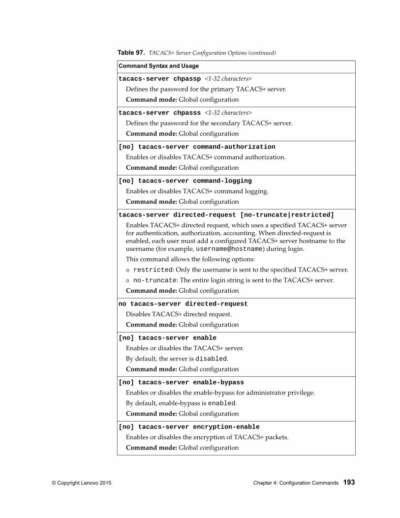
© Copyright Lenovo 2015 Chapter 4: Configuration Commands 193
tacacs-server chpassp <1-32 characters>Defines the password for the primary TACACS+ server.Command mode: Global configuration
tacacs-server chpasss <1-32 characters>Defines the password for the secondary TACACS+ server.Command mode: Global configuration
[no] tacacs-server command-authorization
Enables or disables TACACS+ command authorization.Command mode: Global configuration
[no] tacacs-server command-logging
Enables or disables TACACS+ command logging.Command mode: Global configuration
tacacs-server directed-request [no-truncate|restricted]
Enables TACACS+ directed request, which uses a specified TACACS+ server for authentication, authorization, accounting. When directed-request is enabled, each user must add a configured TACACS+ server hostname to the username (for example, username@hostname) during login.This command allows the following options: restricted: Only the username is sent to the specified TACACS+ server. no-truncate: The entire login string is sent to the TACACS+ server.Command mode: Global configuration
no tacacs-server directed-request
Disables TACACS+ directed request.Command mode: Global configuration
[no] tacacs-server enable
Enables or disables the TACACS+ server.By default, the server is disabled. Command mode: Global configuration
[no] tacacs-server enable-bypass
Enables or disables the enable-bypass for administrator privilege.By default, enable-bypass is enabled.Command mode: Global configuration
[no] tacacs-server encryption-enable
Enables or disables the encryption of TACACS+ packets.Command mode: Global configuration
Table 97. TACACS+ Server Configuration Options (continued)
Command Syntax and Usage
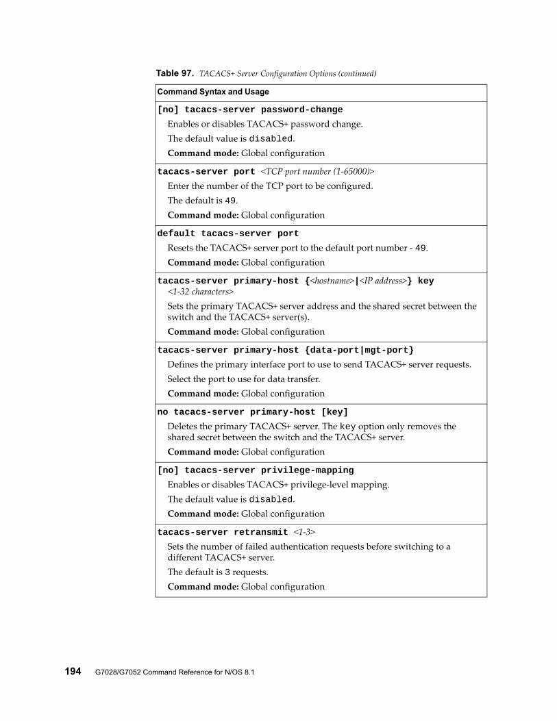
194 G7028/G7052 Command Reference for N/OS 8.1
[no] tacacs-server password-change
Enables or disables TACACS+ password change.The default value is disabled.Command mode: Global configuration
tacacs-server port <TCP port number (1-65000)>Enter the number of the TCP port to be configured.The default is 49.Command mode: Global configuration
default tacacs-server port
Resets the TACACS+ server port to the default port number - 49.Command mode: Global configuration
tacacs-server primary-host {<hostname>|<IP address>} key <1-32 characters>
Sets the primary TACACS+ server address and the shared secret between the switch and the TACACS+ server(s).Command mode: Global configuration
tacacs-server primary-host {data-port|mgt-port}
Defines the primary interface port to use to send TACACS+ server requests.Select the port to use for data transfer.Command mode: Global configuration
no tacacs-server primary-host [key]
Deletes the primary TACACS+ server. The key option only removes the shared secret between the switch and the TACACS+ server.Command mode: Global configuration
[no] tacacs-server privilege-mapping
Enables or disables TACACS+ privilege-level mapping.The default value is disabled.Command mode: Global configuration
tacacs-server retransmit <1-3>Sets the number of failed authentication requests before switching to a different TACACS+ server.The default is 3 requests.Command mode: Global configuration
Table 97. TACACS+ Server Configuration Options (continued)
Command Syntax and Usage
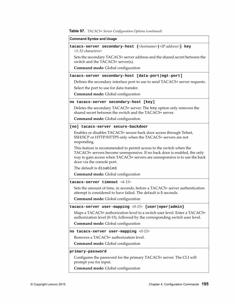
© Copyright Lenovo 2015 Chapter 4: Configuration Commands 195
tacacs-server secondary-host {<hostname>|<IP address>} key <1-32 characters>
Sets the secondary TACACS+ server address and the shared secret between the switch and the TACACS+ server(s).Command mode: Global configuration
tacacs-server secondary-host [data-port|mgt-port]
Defines the secondary interface port to use to send TACACS+ server requests.Select the port to use for data transfer.Command mode: Global configuration
no tacacs-server secondary-host [key]
Deletes the secondary TACACS+ server. The key option only removes the shared secret between the switch and the TACACS+ server.Command mode: Global configuration
[no] tacacs-server secure-backdoor
Enables or disables TACACS+ secure back door access through Telnet, SSH/SCP or HTTP/HTTPS only when the TACACS+ servers are not responding.This feature is recommended to permit access to the switch when the TACACS+ servers become unresponsive. If no back door is enabled, the only way to gain access when TACACS+ servers are unresponsive is to use the back door via the console port.The default is disabled.Command mode: Global configuration
tacacs-server timeout <4-15>Sets the amount of time, in seconds, before a TACACS+ server authentication attempt is considered to have failed. The default is 5 seconds.Command mode: Global configuration
tacacs-server user-mapping <0-15> {user|oper|admin}Maps a TACACS+ authorization level to a switch user level. Enter a TACACS+ authorization level (0-15), followed by the corresponding switch user level. Command mode: Global configuration
no tacacs-server user-mapping <0-15>Removes a TACACS+ authorization level.Command mode: Global configuration
primary-password
Configures the password for the primary TACACS+ server. The CLI will prompt you for input.Command mode: Global configuration
Table 97. TACACS+ Server Configuration Options (continued)
Command Syntax and Usage
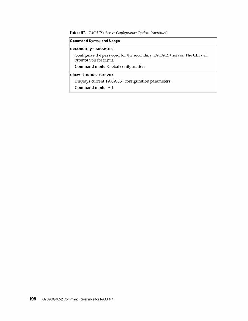
196 G7028/G7052 Command Reference for N/OS 8.1
secondary-password
Configures the password for the secondary TACACS+ server. The CLI will prompt you for input.Command mode: Global configuration
show tacacs-server
Displays current TACACS+ configuration parameters.Command mode: All
Table 97. TACACS+ Server Configuration Options (continued)
Command Syntax and Usage
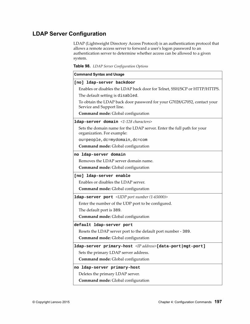
© Copyright Lenovo 2015 Chapter 4: Configuration Commands 197
LDAP Server Configuration
LDAP (Lightweight Directory Access Protocol) is an authentication protocol that allows a remote access server to forward a user's logon password to an authentication server to determine whether access can be allowed to a given system.
Table 98. LDAP Server Configuration Options
Command Syntax and Usage
[no] ldap-server backdoor
Enables or disables the LDAP back door for Telnet, SSH/SCP or HTTP/HTTPS.The default setting is disabled.To obtain the LDAP back door password for your G7028/G7052, contact your Service and Support line.Command mode: Global configuration
ldap-server domain <1-128 characters>Sets the domain name for the LDAP server. Enter the full path for your organization. For example:ou=people,dc=mydomain,dc=com
Command mode: Global configuration
no ldap-server domain
Removes the LDAP server domain name.Command mode: Global configuration
[no] ldap-server enable
Enables or disables the LDAP server.Command mode: Global configuration
ldap-server port <UDP port number (1-65000)>Enter the number of the UDP port to be configured.The default port is 389.Command mode: Global configuration
default ldap-server port
Resets the LDAP server port to the default port number - 389.Command mode: Global configuration
ldap-server primary-host <IP address>[data-port|mgt-port]Sets the primary LDAP server address.Command mode: Global configuration
no ldap-server primary-host
Deletes the primary LDAP server.Command mode: Global configuration
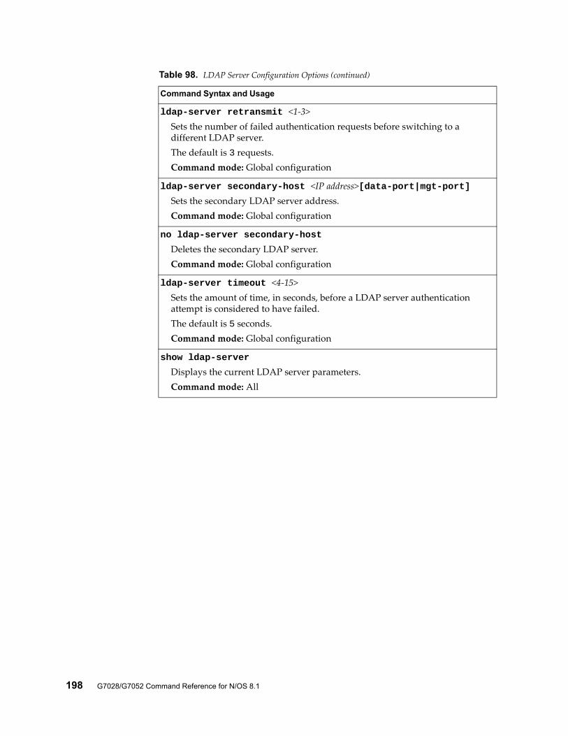
198 G7028/G7052 Command Reference for N/OS 8.1
ldap-server retransmit <1-3>Sets the number of failed authentication requests before switching to a different LDAP server.The default is 3 requests.Command mode: Global configuration
ldap-server secondary-host <IP address>[data-port|mgt-port]Sets the secondary LDAP server address.Command mode: Global configuration
no ldap-server secondary-host
Deletes the secondary LDAP server.Command mode: Global configuration
ldap-server timeout <4-15>Sets the amount of time, in seconds, before a LDAP server authentication attempt is considered to have failed.The default is 5 seconds.Command mode: Global configuration
show ldap-server
Displays the current LDAP server parameters.Command mode: All
Table 98. LDAP Server Configuration Options (continued)
Command Syntax and Usage
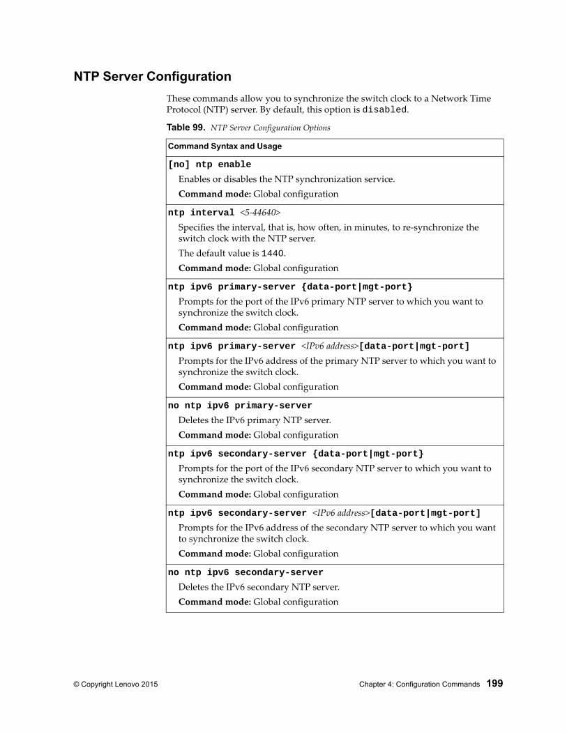
© Copyright Lenovo 2015 Chapter 4: Configuration Commands 199
NTP Server Configuration
These commands allow you to synchronize the switch clock to a Network Time Protocol (NTP) server. By default, this option is disabled.
Table 99. NTP Server Configuration Options
Command Syntax and Usage
[no] ntp enable
Enables or disables the NTP synchronization service.Command mode: Global configuration
ntp interval <5-44640>Specifies the interval, that is, how often, in minutes, to re-synchronize the switch clock with the NTP server.The default value is 1440.Command mode: Global configuration
ntp ipv6 primary-server {data-port|mgt-port}
Prompts for the port of the IPv6 primary NTP server to which you want to synchronize the switch clock.Command mode: Global configuration
ntp ipv6 primary-server <IPv6 address>[data-port|mgt-port]Prompts for the IPv6 address of the primary NTP server to which you want to synchronize the switch clock.Command mode: Global configuration
no ntp ipv6 primary-server
Deletes the IPv6 primary NTP server.Command mode: Global configuration
ntp ipv6 secondary-server {data-port|mgt-port}
Prompts for the port of the IPv6 secondary NTP server to which you want to synchronize the switch clock.Command mode: Global configuration
ntp ipv6 secondary-server <IPv6 address>[data-port|mgt-port]Prompts for the IPv6 address of the secondary NTP server to which you want to synchronize the switch clock.Command mode: Global configuration
no ntp ipv6 secondary-server
Deletes the IPv6 secondary NTP server.Command mode: Global configuration
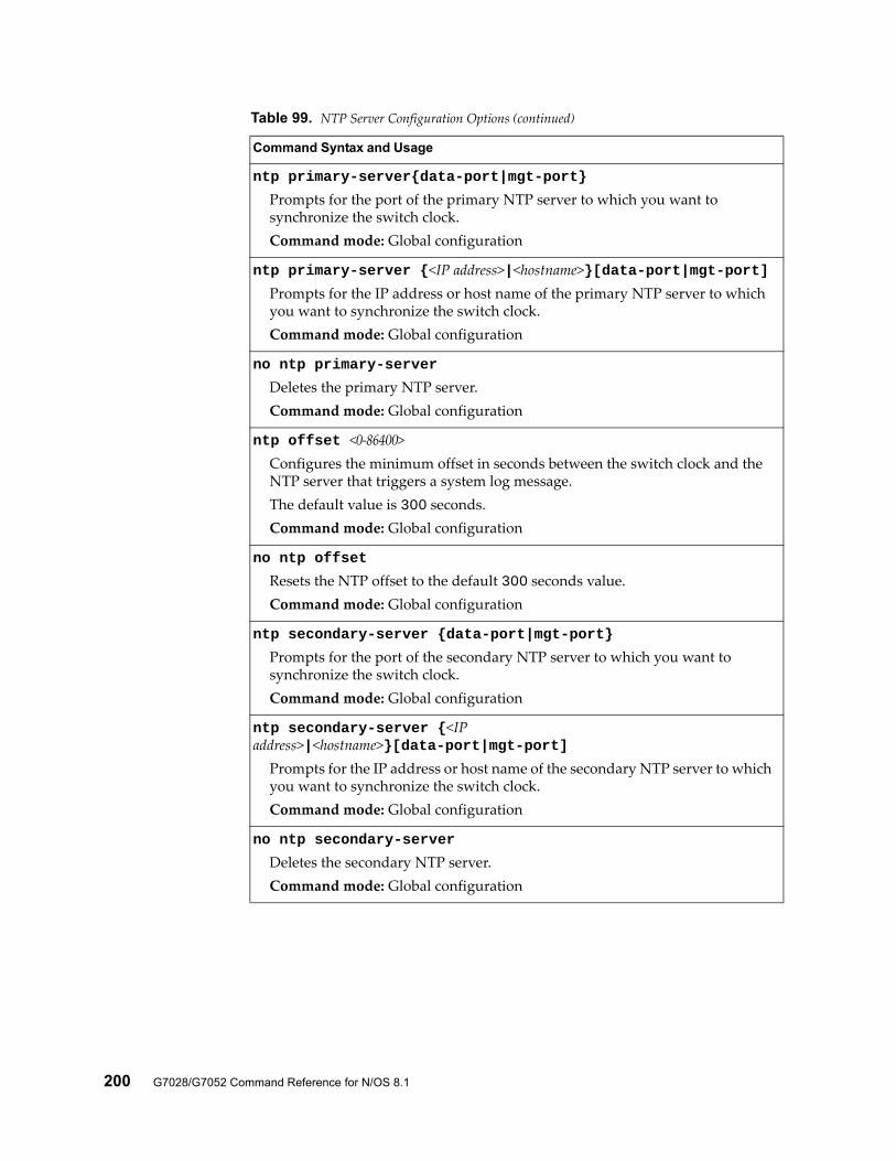
200 G7028/G7052 Command Reference for N/OS 8.1
ntp primary-server{data-port|mgt-port}
Prompts for the port of the primary NTP server to which you want to synchronize the switch clock.Command mode: Global configuration
ntp primary-server {<IP address>|<hostname>}[data-port|mgt-port]Prompts for the IP address or host name of the primary NTP server to which you want to synchronize the switch clock.Command mode: Global configuration
no ntp primary-server
Deletes the primary NTP server.Command mode: Global configuration
ntp offset <0-86400>Configures the minimum offset in seconds between the switch clock and the NTP server that triggers a system log message.The default value is 300 seconds.Command mode: Global configuration
no ntp offset
Resets the NTP offset to the default 300 seconds value.Command mode: Global configuration
ntp secondary-server {data-port|mgt-port}
Prompts for the port of the secondary NTP server to which you want to synchronize the switch clock.Command mode: Global configuration
ntp secondary-server {<IP address>|<hostname>}[data-port|mgt-port]
Prompts for the IP address or host name of the secondary NTP server to which you want to synchronize the switch clock.Command mode: Global configuration
no ntp secondary-server
Deletes the secondary NTP server.Command mode: Global configuration
Table 99. NTP Server Configuration Options (continued)
Command Syntax and Usage
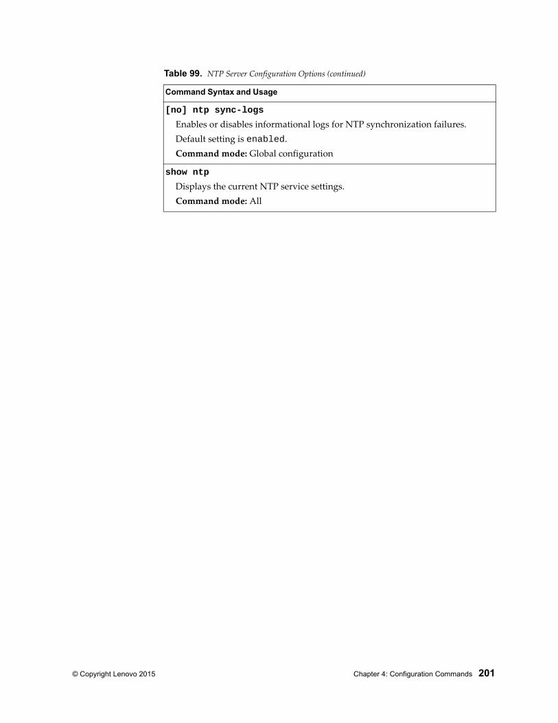
© Copyright Lenovo 2015 Chapter 4: Configuration Commands 201
[no] ntp sync-logs
Enables or disables informational logs for NTP synchronization failures.Default setting is enabled.Command mode: Global configuration
show ntp
Displays the current NTP service settings.Command mode: All
Table 99. NTP Server Configuration Options (continued)
Command Syntax and Usage
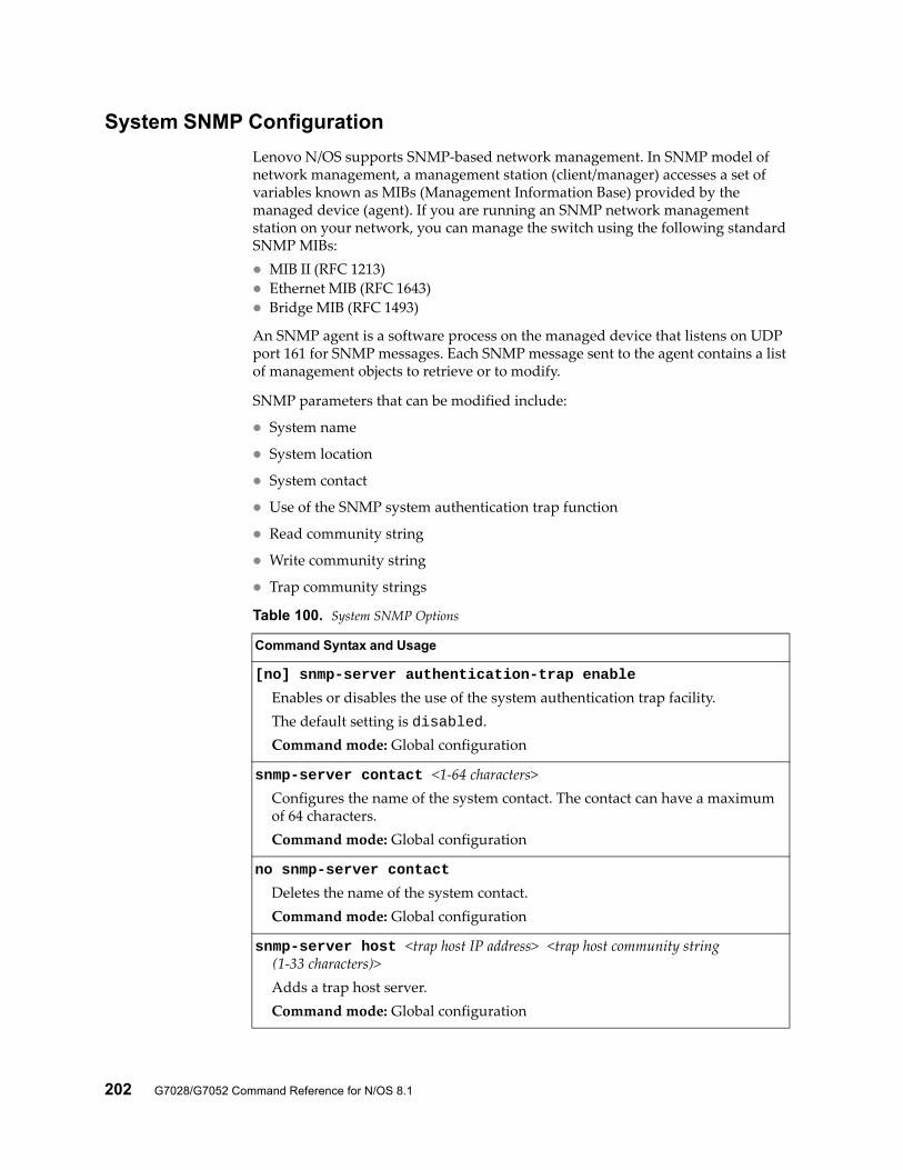
202 G7028/G7052 Command Reference for N/OS 8.1
System SNMP Configuration
Lenovo N/OS supports SNMP-based network management. In SNMP model of network management, a management station (client/manager) accesses a set of variables known as MIBs (Management Information Base) provided by the managed device (agent). If you are running an SNMP network management station on your network, you can manage the switch using the following standard SNMP MIBs: MIB II (RFC 1213) Ethernet MIB (RFC 1643) Bridge MIB (RFC 1493)
An SNMP agent is a software process on the managed device that listens on UDP port 161 for SNMP messages. Each SNMP message sent to the agent contains a list of management objects to retrieve or to modify.
SNMP parameters that can be modified include:
System name
System location
System contact
Use of the SNMP system authentication trap function
Read community string
Write community string
Trap community strings
Table 100. System SNMP Options
Command Syntax and Usage
[no] snmp-server authentication-trap enable
Enables or disables the use of the system authentication trap facility.The default setting is disabled.Command mode: Global configuration
snmp-server contact <1-64 characters>Configures the name of the system contact. The contact can have a maximum of 64 characters.Command mode: Global configuration
no snmp-server contact
Deletes the name of the system contact.Command mode: Global configuration
snmp-server host <trap host IP address> <trap host community string (1-33 characters)>
Adds a trap host server.Command mode: Global configuration
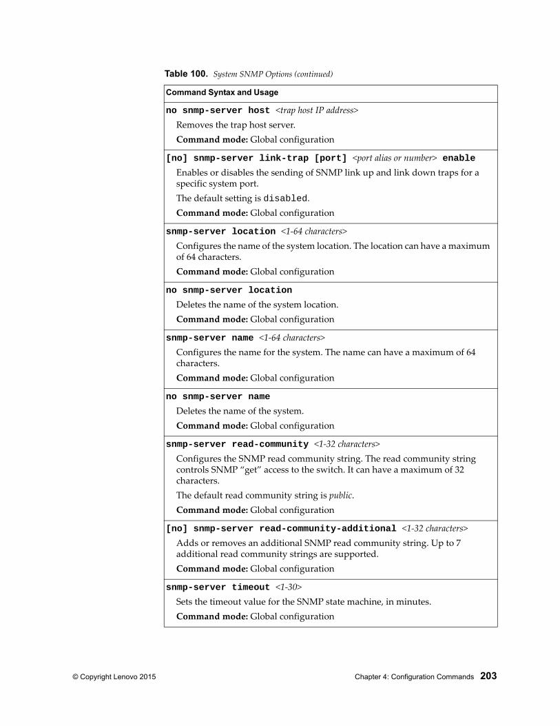
© Copyright Lenovo 2015 Chapter 4: Configuration Commands 203
no snmp-server host <trap host IP address>Removes the trap host server.Command mode: Global configuration
[no] snmp-server link-trap [port] <port alias or number> enableEnables or disables the sending of SNMP link up and link down traps for a specific system port.The default setting is disabled.Command mode: Global configuration
snmp-server location <1-64 characters>Configures the name of the system location. The location can have a maximum of 64 characters.Command mode: Global configuration
no snmp-server location
Deletes the name of the system location.Command mode: Global configuration
snmp-server name <1-64 characters>Configures the name for the system. The name can have a maximum of 64 characters.Command mode: Global configuration
no snmp-server name
Deletes the name of the system.Command mode: Global configuration
snmp-server read-community <1-32 characters>Configures the SNMP read community string. The read community string controls SNMP “get” access to the switch. It can have a maximum of 32 characters.The default read community string is public.Command mode: Global configuration
[no] snmp-server read-community-additional <1-32 characters>Adds or removes an additional SNMP read community string. Up to 7 additional read community strings are supported.Command mode: Global configuration
snmp-server timeout <1-30>Sets the timeout value for the SNMP state machine, in minutes.Command mode: Global configuration
Table 100. System SNMP Options (continued)
Command Syntax and Usage
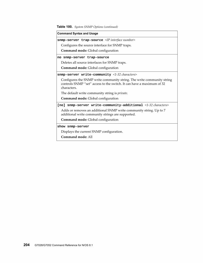
204 G7028/G7052 Command Reference for N/OS 8.1
snmp-server trap-source <IP interface number>Configures the source interface for SNMP traps.Command mode: Global configuration
no snmp-server trap-source
Deletes all source interfaces for SNMP traps.Command mode: Global configuration
snmp-server write-community <1-32 characters>Configures the SNMP write community string. The write community string controls SNMP “set” access to the switch. It can have a maximum of 32 characters.The default write community string is private.Command mode: Global configuration
[no] snmp-server write-community-additional <1-32 characters>Adds or removes an additional SNMP write community string. Up to 7 additional write community strings are supported.Command mode: Global configuration
show snmp-server
Displays the current SNMP configuration.Command mode: All
Table 100. System SNMP Options (continued)
Command Syntax and Usage
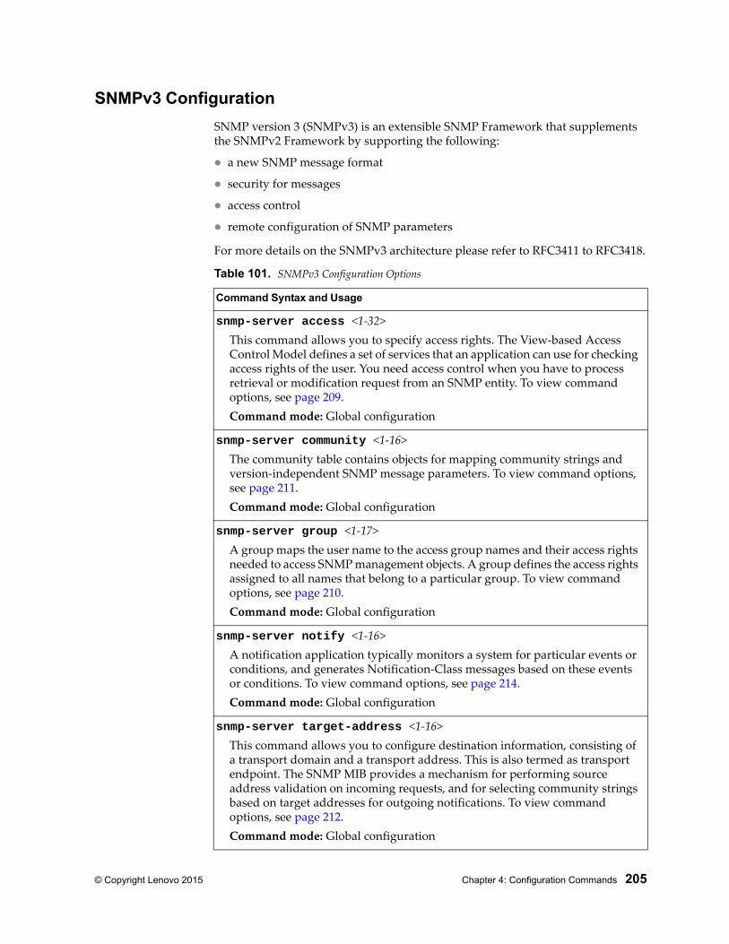
© Copyright Lenovo 2015 Chapter 4: Configuration Commands 205
SNMPv3 Configuration
SNMP version 3 (SNMPv3) is an extensible SNMP Framework that supplements the SNMPv2 Framework by supporting the following:
a new SNMP message format
security for messages
access control
remote configuration of SNMP parameters
For more details on the SNMPv3 architecture please refer to RFC3411 to RFC3418.
Table 101. SNMPv3 Configuration Options
Command Syntax and Usage
snmp-server access <1-32>This command allows you to specify access rights. The View-based Access Control Model defines a set of services that an application can use for checking access rights of the user. You need access control when you have to process retrieval or modification request from an SNMP entity. To view command options, see page 209.Command mode: Global configuration
snmp-server community <1-16>The community table contains objects for mapping community strings and version-independent SNMP message parameters. To view command options, see page 211.Command mode: Global configuration
snmp-server group <1-17>A group maps the user name to the access group names and their access rights needed to access SNMP management objects. A group defines the access rights assigned to all names that belong to a particular group. To view command options, see page 210.Command mode: Global configuration
snmp-server notify <1-16>A notification application typically monitors a system for particular events or conditions, and generates Notification-Class messages based on these events or conditions. To view command options, see page 214.Command mode: Global configuration
snmp-server target-address <1-16>This command allows you to configure destination information, consisting of a transport domain and a transport address. This is also termed as transport endpoint. The SNMP MIB provides a mechanism for performing source address validation on incoming requests, and for selecting community strings based on target addresses for outgoing notifications. To view command options, see page 212.Command mode: Global configuration
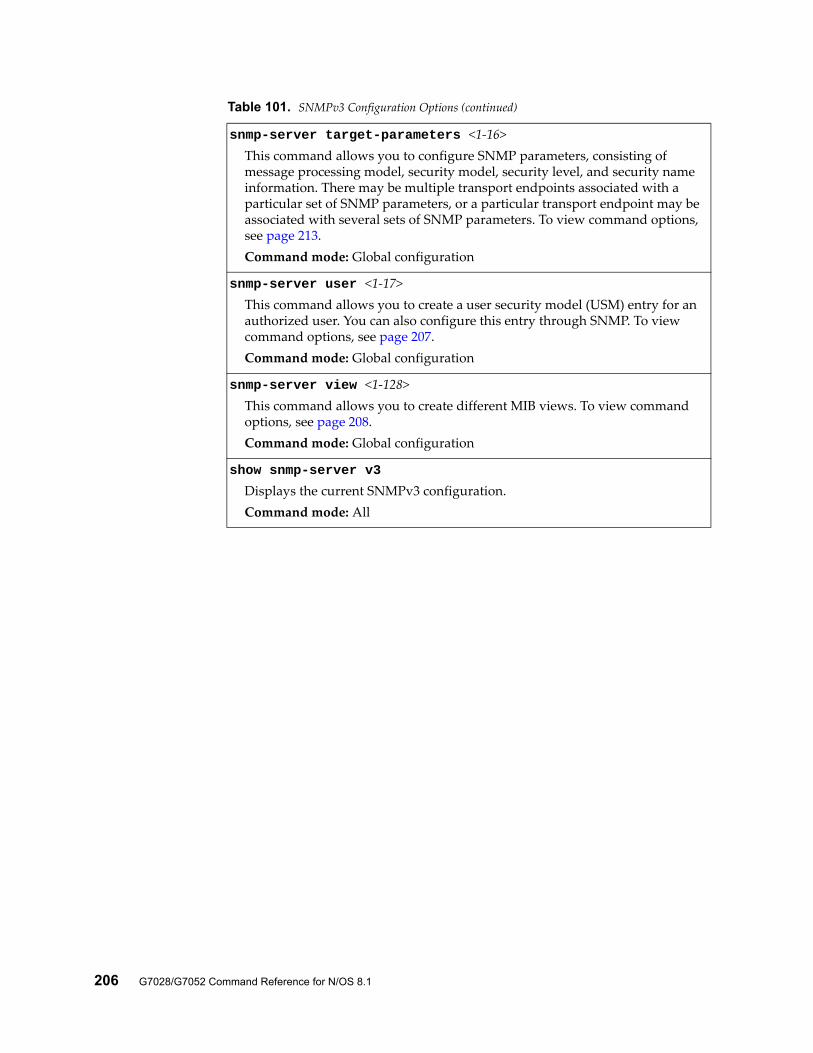
206 G7028/G7052 Command Reference for N/OS 8.1
snmp-server target-parameters <1-16>This command allows you to configure SNMP parameters, consisting of message processing model, security model, security level, and security name information. There may be multiple transport endpoints associated with a particular set of SNMP parameters, or a particular transport endpoint may be associated with several sets of SNMP parameters. To view command options, see page 213.Command mode: Global configuration
snmp-server user <1-17>This command allows you to create a user security model (USM) entry for an authorized user. You can also configure this entry through SNMP. To view command options, see page 207.Command mode: Global configuration
snmp-server view <1-128>This command allows you to create different MIB views. To view command options, see page 208.Command mode: Global configuration
show snmp-server v3
Displays the current SNMPv3 configuration.Command mode: All
Table 101. SNMPv3 Configuration Options (continued)
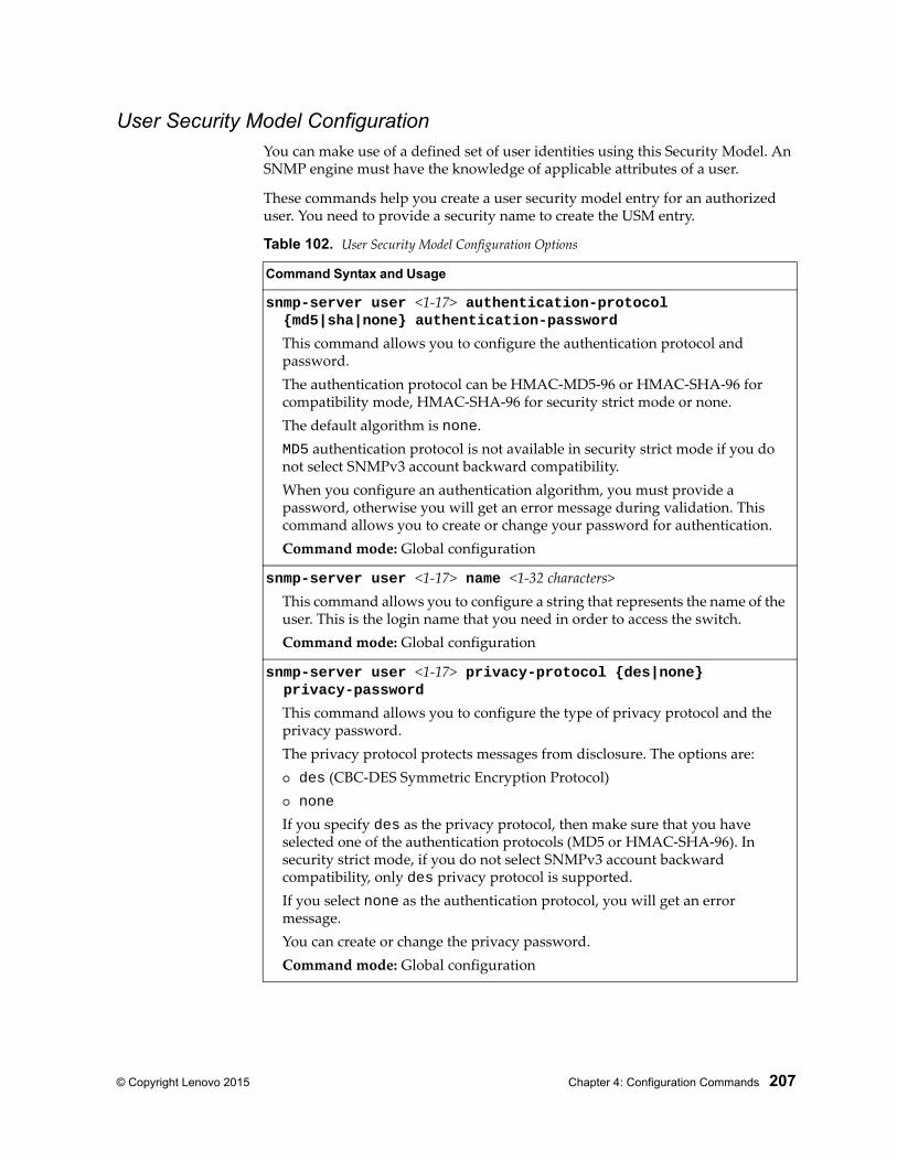
© Copyright Lenovo 2015 Chapter 4: Configuration Commands 207
User Security Model ConfigurationYou can make use of a defined set of user identities using this Security Model. An SNMP engine must have the knowledge of applicable attributes of a user.
These commands help you create a user security model entry for an authorized user. You need to provide a security name to create the USM entry.
Table 102. User Security Model Configuration Options
Command Syntax and Usage
snmp-server user <1-17> authentication-protocol {md5|sha|none} authentication-password
This command allows you to configure the authentication protocol and password.The authentication protocol can be HMAC-MD5-96 or HMAC-SHA-96 for compatibility mode, HMAC-SHA-96 for security strict mode or none.The default algorithm is none.MD5 authentication protocol is not available in security strict mode if you do not select SNMPv3 account backward compatibility.When you configure an authentication algorithm, you must provide a password, otherwise you will get an error message during validation. This command allows you to create or change your password for authentication.Command mode: Global configuration
snmp-server user <1-17> name <1-32 characters>This command allows you to configure a string that represents the name of the user. This is the login name that you need in order to access the switch.Command mode: Global configuration
snmp-server user <1-17> privacy-protocol {des|none} privacy-password
This command allows you to configure the type of privacy protocol and the privacy password.The privacy protocol protects messages from disclosure. The options are: des (CBC-DES Symmetric Encryption Protocol) none
If you specify des as the privacy protocol, then make sure that you have selected one of the authentication protocols (MD5 or HMAC-SHA-96). In security strict mode, if you do not select SNMPv3 account backward compatibility, only des privacy protocol is supported.If you select none as the authentication protocol, you will get an error message.You can create or change the privacy password.Command mode: Global configuration
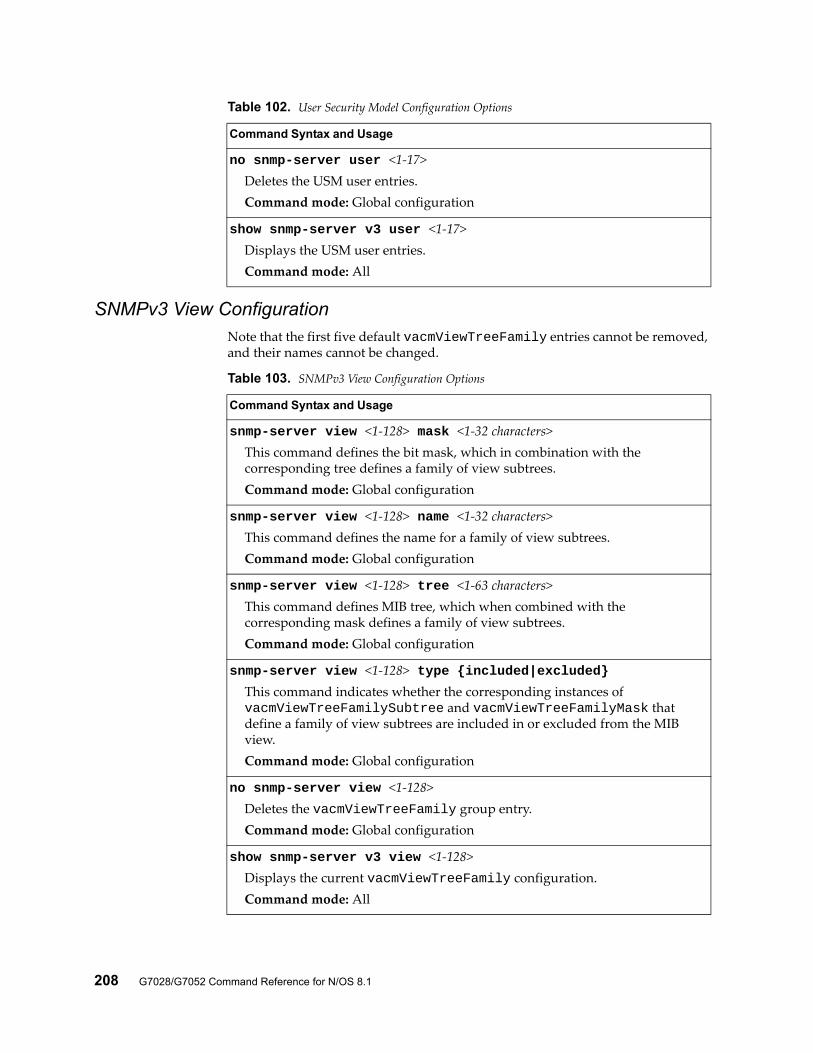
208 G7028/G7052 Command Reference for N/OS 8.1
SNMPv3 View ConfigurationNote that the first five default vacmViewTreeFamily entries cannot be removed, and their names cannot be changed.
no snmp-server user <1-17>Deletes the USM user entries.Command mode: Global configuration
show snmp-server v3 user <1-17>Displays the USM user entries.Command mode: All
Table 102. User Security Model Configuration Options
Command Syntax and Usage
Table 103. SNMPv3 View Configuration Options
Command Syntax and Usage
snmp-server view <1-128> mask <1-32 characters>This command defines the bit mask, which in combination with the corresponding tree defines a family of view subtrees.Command mode: Global configuration
snmp-server view <1-128> name <1-32 characters>This command defines the name for a family of view subtrees.Command mode: Global configuration
snmp-server view <1-128> tree <1-63 characters>This command defines MIB tree, which when combined with the corresponding mask defines a family of view subtrees.Command mode: Global configuration
snmp-server view <1-128> type {included|excluded}This command indicates whether the corresponding instances of vacmViewTreeFamilySubtree and vacmViewTreeFamilyMask that define a family of view subtrees are included in or excluded from the MIB view.Command mode: Global configuration
no snmp-server view <1-128>Deletes the vacmViewTreeFamily group entry.Command mode: Global configuration
show snmp-server v3 view <1-128>Displays the current vacmViewTreeFamily configuration.Command mode: All
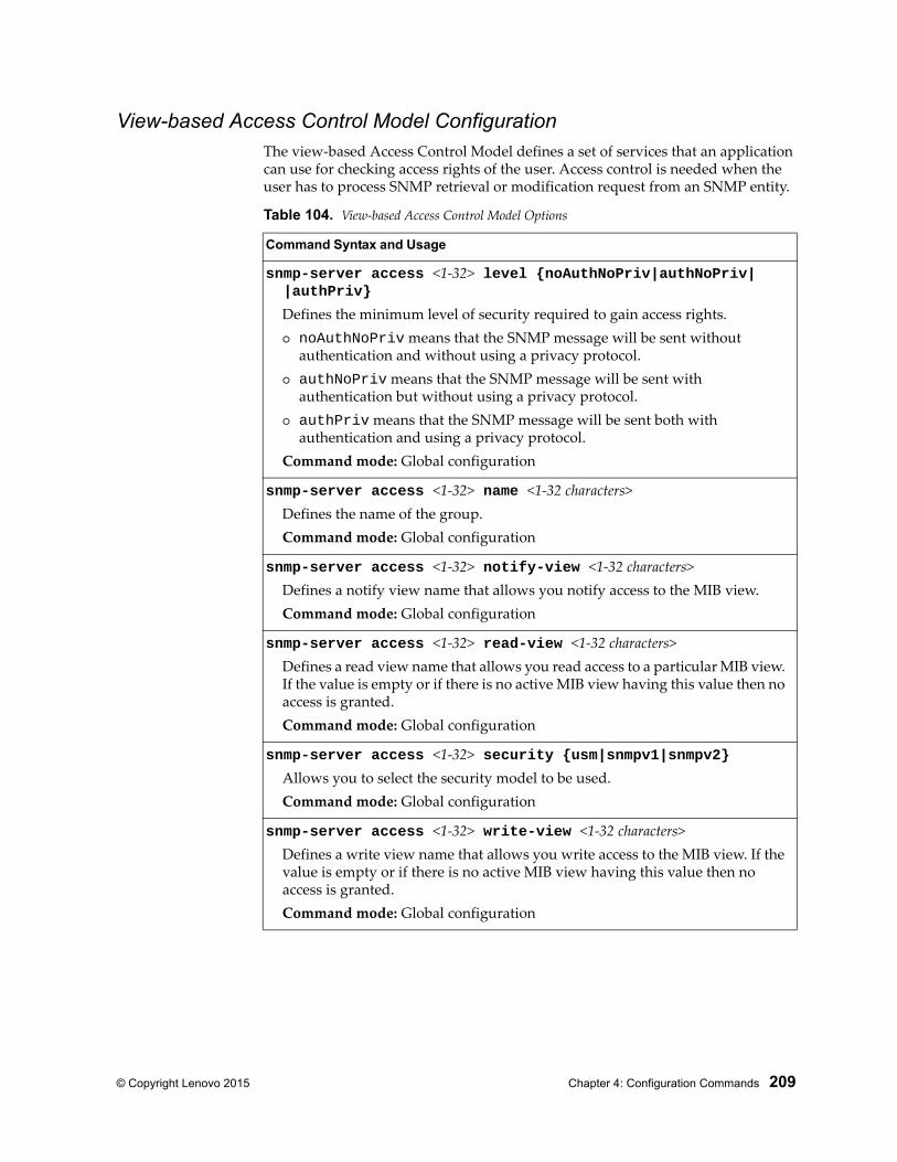
© Copyright Lenovo 2015 Chapter 4: Configuration Commands 209
View-based Access Control Model ConfigurationThe view-based Access Control Model defines a set of services that an application can use for checking access rights of the user. Access control is needed when the user has to process SNMP retrieval or modification request from an SNMP entity.
Table 104. View-based Access Control Model Options
Command Syntax and Usage
snmp-server access <1-32> level {noAuthNoPriv|authNoPriv| |authPriv}
Defines the minimum level of security required to gain access rights. noAuthNoPriv means that the SNMP message will be sent without
authentication and without using a privacy protocol. authNoPriv means that the SNMP message will be sent with
authentication but without using a privacy protocol. authPriv means that the SNMP message will be sent both with
authentication and using a privacy protocol.Command mode: Global configuration
snmp-server access <1-32> name <1-32 characters>Defines the name of the group.Command mode: Global configuration
snmp-server access <1-32> notify-view <1-32 characters>Defines a notify view name that allows you notify access to the MIB view.Command mode: Global configuration
snmp-server access <1-32> read-view <1-32 characters>Defines a read view name that allows you read access to a particular MIB view. If the value is empty or if there is no active MIB view having this value then no access is granted.Command mode: Global configuration
snmp-server access <1-32> security {usm|snmpv1|snmpv2}Allows you to select the security model to be used.Command mode: Global configuration
snmp-server access <1-32> write-view <1-32 characters>Defines a write view name that allows you write access to the MIB view. If the value is empty or if there is no active MIB view having this value then no access is granted.Command mode: Global configuration
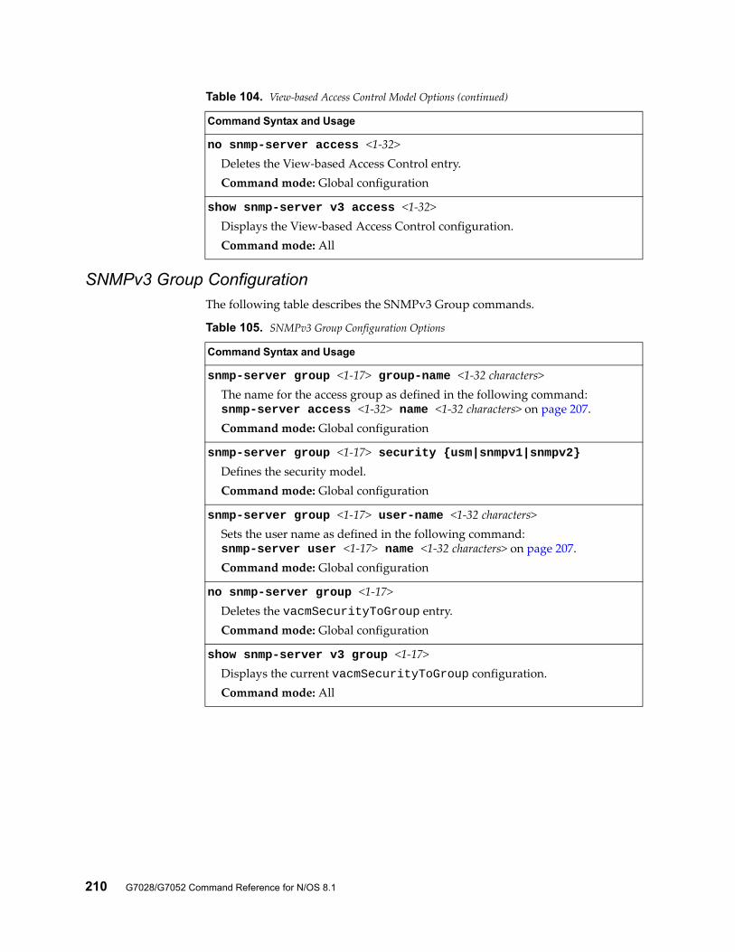
210 G7028/G7052 Command Reference for N/OS 8.1
SNMPv3 Group ConfigurationThe following table describes the SNMPv3 Group commands.
no snmp-server access <1-32>Deletes the View-based Access Control entry.Command mode: Global configuration
show snmp-server v3 access <1-32>Displays the View-based Access Control configuration.Command mode: All
Table 104. View-based Access Control Model Options (continued)
Command Syntax and Usage
Table 105. SNMPv3 Group Configuration Options
Command Syntax and Usage
snmp-server group <1-17> group-name <1-32 characters>The name for the access group as defined in the following command:snmp-server access <1-32> name <1-32 characters> on page 207.Command mode: Global configuration
snmp-server group <1-17> security {usm|snmpv1|snmpv2}Defines the security model.Command mode: Global configuration
snmp-server group <1-17> user-name <1-32 characters>Sets the user name as defined in the following command:snmp-server user <1-17> name <1-32 characters> on page 207.Command mode: Global configuration
no snmp-server group <1-17>Deletes the vacmSecurityToGroup entry.Command mode: Global configuration
show snmp-server v3 group <1-17>Displays the current vacmSecurityToGroup configuration.Command mode: All
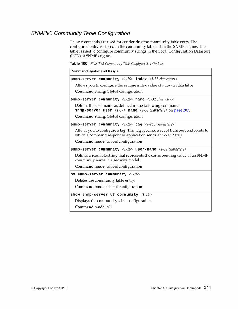
© Copyright Lenovo 2015 Chapter 4: Configuration Commands 211
SNMPv3 Community Table Configuration
These commands are used for configuring the community table entry. The configured entry is stored in the community table list in the SNMP engine. This table is used to configure community strings in the Local Configuration Datastore (LCD) of SNMP engine.
Table 106. SNMPv3 Community Table Configuration Options
Command Syntax and Usage
snmp-server community <1-16> index <1-32 characters>Allows you to configure the unique index value of a row in this table.Command string: Global configuration
snmp-server community <1-16> name <1-32 characters>Defines the user name as defined in the following command:snmp-server user <1-17> name <1-32 characters> on page 207.Command string: Global configuration
snmp-server community <1-16> tag <1-255 characters>Allows you to configure a tag. This tag specifies a set of transport endpoints to which a command responder application sends an SNMP trap.Command mode: Global configuration
snmp-server community <1-16> user-name <1-32 characters>Defines a readable string that represents the corresponding value of an SNMP community name in a security model.Command mode: Global configuration
no snmp-server community <1-16>Deletes the community table entry.Command mode: Global configuration
show snmp-server v3 community <1-16>Displays the community table configuration.Command mode: All
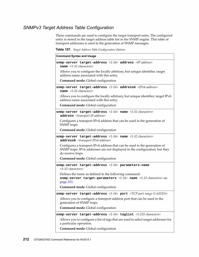
212 G7028/G7052 Command Reference for N/OS 8.1
SNMPv3 Target Address Table Configuration
These commands are used to configure the target transport entry. The configured entry is stored in the target address table list in the SNMP engine. This table of transport addresses is used in the generation of SNMP messages.
Table 107. Target Address Table Configuration Options
Command Syntax and Usage
snmp-server target-address <1-16> address <IP address> name <1-32 characters>
Allows you to configure the locally arbitrary, but unique identifier, target address name associated with this entry.Command mode: Global configuration
snmp-server target-address <1-16> address6 <IPv6 address> name <1-32 characters>
Allows you to configure the locally arbitrary, but unique identifier, target IPv6 address name associated with this entry.Command mode: Global configuration
snmp-server target-address <1-16> name <1-32 characters> address <transport IP address>
Configures a transport IPv4 address that can be used in the generation of SNMP traps.Command mode: Global configuration
snmp-server target-address <1-16> name <1-32 characters> address6 <transport IPv6 address>
Configures a transport IPv6 address that can be used in the generation of SNMP traps. IPv6 addresses are not displayed in the configuration, but they do receive traps.Command mode: Global configuration
snmp-server target-address <1-16> parameters-name <1-32 characters>
Defines the name as defined in the following command:snmp-server target-parameters <1-16> name <1-32 characters> on page 213.Command mode: Global configuration
snmp-server target-address <1-16> port <TCP port range (1-65535)>Allows you to configure a transport address port that can be used in the generation of SNMP traps.Command mode: Global configuration
snmp-server target-address <1-16> taglist <1-255 characters>Allows you to configure a list of tags that are used to select target addresses for a particular operation.Command mode: Global configuration
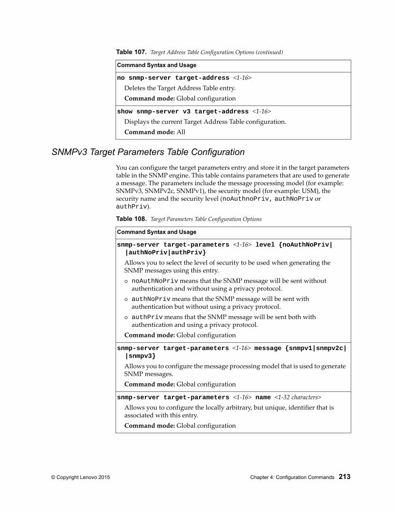
© Copyright Lenovo 2015 Chapter 4: Configuration Commands 213
SNMPv3 Target Parameters Table Configuration
You can configure the target parameters entry and store it in the target parameters table in the SNMP engine. This table contains parameters that are used to generate a message. The parameters include the message processing model (for example: SNMPv3, SNMPv2c, SNMPv1), the security model (for example: USM), the security name and the security level (noAuthnoPriv, authNoPriv or authPriv).
no snmp-server target-address <1-16>Deletes the Target Address Table entry.Command mode: Global configuration
show snmp-server v3 target-address <1-16>Displays the current Target Address Table configuration.Command mode: All
Table 107. Target Address Table Configuration Options (continued)
Command Syntax and Usage
Table 108. Target Parameters Table Configuration Options
Command Syntax and Usage
snmp-server target-parameters <1-16> level {noAuthNoPriv| |authNoPriv|authPriv}
Allows you to select the level of security to be used when generating the SNMP messages using this entry. noAuthNoPriv means that the SNMP message will be sent without
authentication and without using a privacy protocol. authNoPriv means that the SNMP message will be sent with
authentication but without using a privacy protocol. authPriv means that the SNMP message will be sent both with
authentication and using a privacy protocol.Command mode: Global configuration
snmp-server target-parameters <1-16> message {snmpv1|snmpv2c| |snmpv3}
Allows you to configure the message processing model that is used to generate SNMP messages.Command mode: Global configuration
snmp-server target-parameters <1-16> name <1-32 characters>Allows you to configure the locally arbitrary, but unique, identifier that is associated with this entry.Command mode: Global configuration
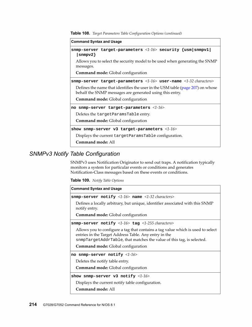
214 G7028/G7052 Command Reference for N/OS 8.1
SNMPv3 Notify Table ConfigurationSNMPv3 uses Notification Originator to send out traps. A notification typically monitors a system for particular events or conditions and generates Notification-Class messages based on these events or conditions.
snmp-server target-parameters <1-16> security {usm|snmpv1| |snmpv2}
Allows you to select the security model to be used when generating the SNMP messages.Command mode: Global configuration
snmp-server target-parameters <1-16> user-name <1-32 characters>Defines the name that identifies the user in the USM table (page 207) on whose behalf the SNMP messages are generated using this entry.Command mode: Global configuration
no snmp-server target-parameters <1-16>Deletes the targetParamsTable entry.Command mode: Global configuration
show snmp-server v3 target-parameters <1-16>Displays the current targetParamsTable configuration.Command mode: All
Table 108. Target Parameters Table Configuration Options (continued)
Command Syntax and Usage
Table 109. Notify Table Options
Command Syntax and Usage
snmp-server notify <1-16> name <1-32 characters>Defines a locally arbitrary, but unique, identifier associated with this SNMP notify entry.Command mode: Global configuration
snmp-server notify <1-16> tag <1-255 characters>Allows you to configure a tag that contains a tag value which is used to select entries in the Target Address Table. Any entry in the snmpTargetAddrTable, that matches the value of this tag, is selected.Command mode: Global configuration
no snmp-server notify <1-16>Deletes the notify table entry.Command mode: Global configuration
show snmp-server v3 notify <1-16>Displays the current notify table configuration.Command mode: All
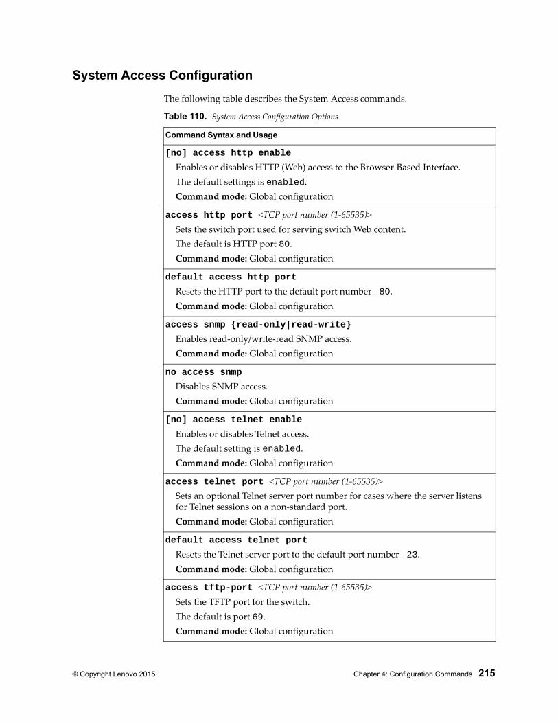
© Copyright Lenovo 2015 Chapter 4: Configuration Commands 215
System Access Configuration
The following table describes the System Access commands.
Table 110. System Access Configuration Options
Command Syntax and Usage
[no] access http enable
Enables or disables HTTP (Web) access to the Browser-Based Interface.The default settings is enabled.Command mode: Global configuration
access http port <TCP port number (1-65535)>Sets the switch port used for serving switch Web content.The default is HTTP port 80.Command mode: Global configuration
default access http port
Resets the HTTP port to the default port number - 80.Command mode: Global configuration
access snmp {read-only|read-write}
Enables read-only/write-read SNMP access.Command mode: Global configuration
no access snmp
Disables SNMP access.Command mode: Global configuration
[no] access telnet enable
Enables or disables Telnet access.The default setting is enabled.Command mode: Global configuration
access telnet port <TCP port number (1-65535)>Sets an optional Telnet server port number for cases where the server listens for Telnet sessions on a non-standard port.Command mode: Global configuration
default access telnet port
Resets the Telnet server port to the default port number - 23.Command mode: Global configuration
access tftp-port <TCP port number (1-65535)>Sets the TFTP port for the switch.The default is port 69.Command mode: Global configuration
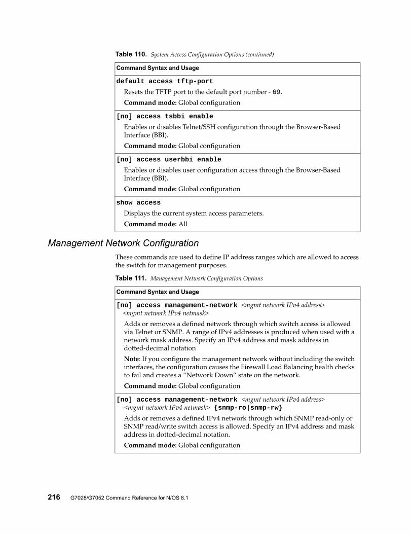
216 G7028/G7052 Command Reference for N/OS 8.1
Management Network ConfigurationThese commands are used to define IP address ranges which are allowed to access the switch for management purposes.
default access tftp-port
Resets the TFTP port to the default port number - 69.Command mode: Global configuration
[no] access tsbbi enable
Enables or disables Telnet/SSH configuration through the Browser-Based Interface (BBI).Command mode: Global configuration
[no] access userbbi enable
Enables or disables user configuration access through the Browser-Based Interface (BBI).Command mode: Global configuration
show access
Displays the current system access parameters.Command mode: All
Table 110. System Access Configuration Options (continued)
Command Syntax and Usage
Table 111. Management Network Configuration Options
Command Syntax and Usage
[no] access management-network <mgmt network IPv4 address> <mgmt network IPv4 netmask>
Adds or removes a defined network through which switch access is allowed via Telnet or SNMP. A range of IPv4 addresses is produced when used with a network mask address. Specify an IPv4 address and mask address in dotted-decimal notationNote: If you configure the management network without including the switch interfaces, the configuration causes the Firewall Load Balancing health checks to fail and creates a “Network Down” state on the network.Command mode: Global configuration
[no] access management-network <mgmt network IPv4 address> <mgmt network IPv4 netmask> {snmp-ro|snmp-rw}
Adds or removes a defined IPv4 network through which SNMP read-only or SNMP read/write switch access is allowed. Specify an IPv4 address and mask address in dotted-decimal notation.Command mode: Global configuration
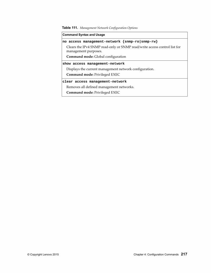
© Copyright Lenovo 2015 Chapter 4: Configuration Commands 217
no access management-network {snmp-ro|snmp-rw}
Clears the IPv4 SNMP read-only or SNMP read/write access control list for management purposes.Command mode: Global configuration
show access management-network
Displays the current management network configuration.Command mode: Privileged EXEC
clear access management-network
Removes all defined management networks.Command mode: Privileged EXEC
Table 111. Management Network Configuration Options
Command Syntax and Usage
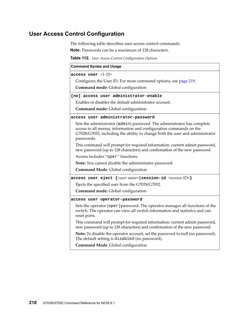
218 G7028/G7052 Command Reference for N/OS 8.1
User Access Control Configuration
The following table describes user-access control commands.Note: Passwords can be a maximum of 128 characters.
Table 112. User Access Control Configuration Options
Command Syntax and Usage
access user <1-20>Configures the User ID. For more command options, see page 219.Command mode: Global configuration
[no] access user administrator-enable
Enables or disables the default administrator account.Command mode: Global configuration
access user administrator-password
Sets the administrator (admin) password. The administrator has complete access to all menus, information and configuration commands on the G7028/G7052, including the ability to change both the user and administrator passwords.This command will prompt for required information: current admin password, new password (up to 128 characters) and confirmation of the new password.Access includes “oper” functions.Note: You cannot disable the administrator password.Command Mode: Global configuration
access user eject {<user name>|session-id <session ID>}Ejects the specified user from the G7028/G7052.Command mode: Global configuration
access user operator-password
Sets the operator (oper)password. The operator manages all functions of the switch. The operator can view all switch information and statistics and can reset ports.This command will prompt for required information: current admin password, new password (up to 128 characters) and confirmation of the new password.Note: To disable the operator account, set the password to null (no password). The default setting is disabled (no password).Command Mode: Global configuration
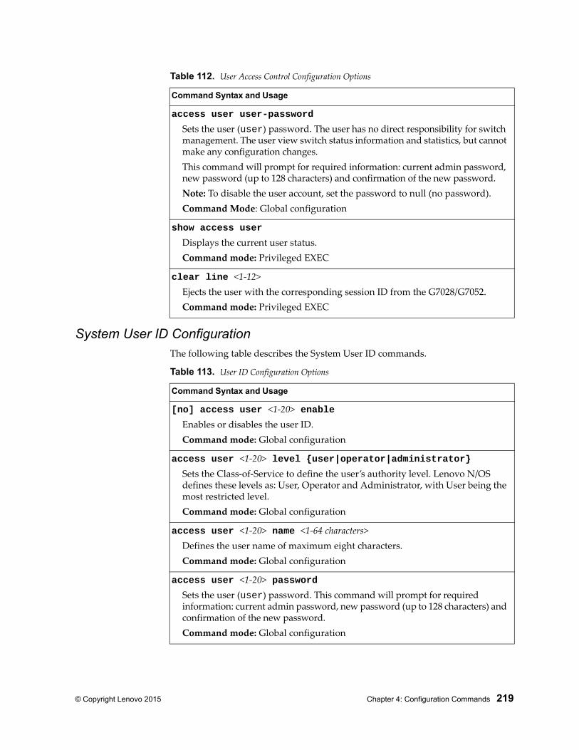
© Copyright Lenovo 2015 Chapter 4: Configuration Commands 219
System User ID Configuration The following table describes the System User ID commands.
access user user-password
Sets the user (user) password. The user has no direct responsibility for switch management. The user view switch status information and statistics, but cannot make any configuration changes.This command will prompt for required information: current admin password, new password (up to 128 characters) and confirmation of the new password.Note: To disable the user account, set the password to null (no password).Command Mode: Global configuration
show access user
Displays the current user status.Command mode: Privileged EXEC
clear line <1-12>Ejects the user with the corresponding session ID from the G7028/G7052.Command mode: Privileged EXEC
Table 112. User Access Control Configuration Options
Command Syntax and Usage
Table 113. User ID Configuration Options
Command Syntax and Usage
[no] access user <1-20> enableEnables or disables the user ID.Command mode: Global configuration
access user <1-20> level {user|operator|administrator}Sets the Class-of-Service to define the user’s authority level. Lenovo N/OS defines these levels as: User, Operator and Administrator, with User being the most restricted level.Command mode: Global configuration
access user <1-20> name <1-64 characters>Defines the user name of maximum eight characters.Command mode: Global configuration
access user <1-20> passwordSets the user (user) password. This command will prompt for required information: current admin password, new password (up to 128 characters) and confirmation of the new password.Command mode: Global configuration
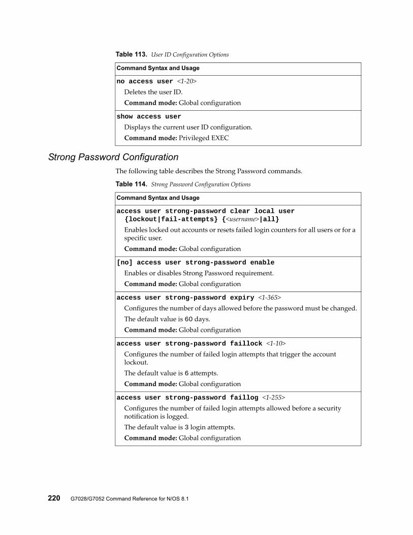
220 G7028/G7052 Command Reference for N/OS 8.1
Strong Password ConfigurationThe following table describes the Strong Password commands.
no access user <1-20>Deletes the user ID.Command mode: Global configuration
show access user
Displays the current user ID configuration.Command mode: Privileged EXEC
Table 113. User ID Configuration Options
Command Syntax and Usage
Table 114. Strong Password Configuration Options
Command Syntax and Usage
access user strong-password clear local user {lockout|fail-attempts} {<username>|all}
Enables locked out accounts or resets failed login counters for all users or for a specific user.Command mode: Global configuration
[no] access user strong-password enable
Enables or disables Strong Password requirement.Command mode: Global configuration
access user strong-password expiry <1-365>Configures the number of days allowed before the password must be changed.The default value is 60 days.Command mode: Global configuration
access user strong-password faillock <1-10>Configures the number of failed login attempts that trigger the account lockout.The default value is 6 attempts.Command mode: Global configuration
access user strong-password faillog <1-255>Configures the number of failed login attempts allowed before a security notification is logged.The default value is 3 login attempts.Command mode: Global configuration
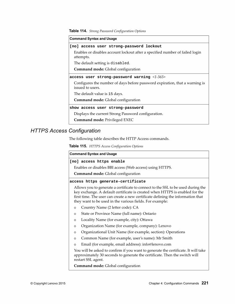
© Copyright Lenovo 2015 Chapter 4: Configuration Commands 221
HTTPS Access Configuration The following table describes the HTTP Access commands.
[no] access user strong-password lockout
Enables or disables account lockout after a specified number of failed login attempts.The default setting is disabled.Command mode: Global configuration
access user strong-password warning <1-365>Configures the number of days before password expiration, that a warning is issued to users.The default value is 15 days.Command mode: Global configuration
show access user strong-password
Displays the current Strong Password configuration.Command mode: Privileged EXEC
Table 114. Strong Password Configuration Options
Command Syntax and Usage
Table 115. HTTPS Access Configuration Options
Command Syntax and Usage
[no] access https enable
Enables or disables BBI access (Web access) using HTTPS.Command mode: Global configuration
access https generate-certificate
Allows you to generate a certificate to connect to the SSL to be used during the key exchange. A default certificate is created when HTTPS is enabled for the first time. The user can create a new certificate defining the information that they want to be used in the various fields. For example: Country Name (2 letter code): CA State or Province Name (full name): Ontario Locality Name (for example, city): Ottawa Organization Name (for example, company): Lenovo Organizational Unit Name (for example, section): Operations Common Name (for example, user’s name): Mr Smith Email (for example, email address): [email protected] will be asked to confirm if you want to generate the certificate. It will take approximately 30 seconds to generate the certificate. Then the switch will restart SSL agent.Command mode: Global configuration
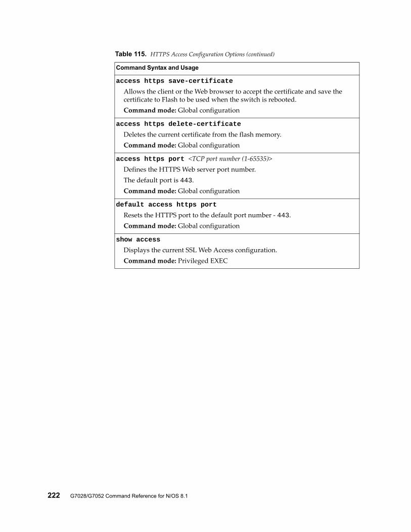
222 G7028/G7052 Command Reference for N/OS 8.1
access https save-certificate
Allows the client or the Web browser to accept the certificate and save the certificate to Flash to be used when the switch is rebooted.Command mode: Global configuration
access https delete-certificate
Deletes the current certificate from the flash memory.Command mode: Global configuration
access https port <TCP port number (1-65535)>Defines the HTTPS Web server port number.The default port is 443.Command mode: Global configuration
default access https port
Resets the HTTPS port to the default port number - 443.Command mode: Global configuration
show access
Displays the current SSL Web Access configuration.Command mode: Privileged EXEC
Table 115. HTTPS Access Configuration Options (continued)
Command Syntax and Usage
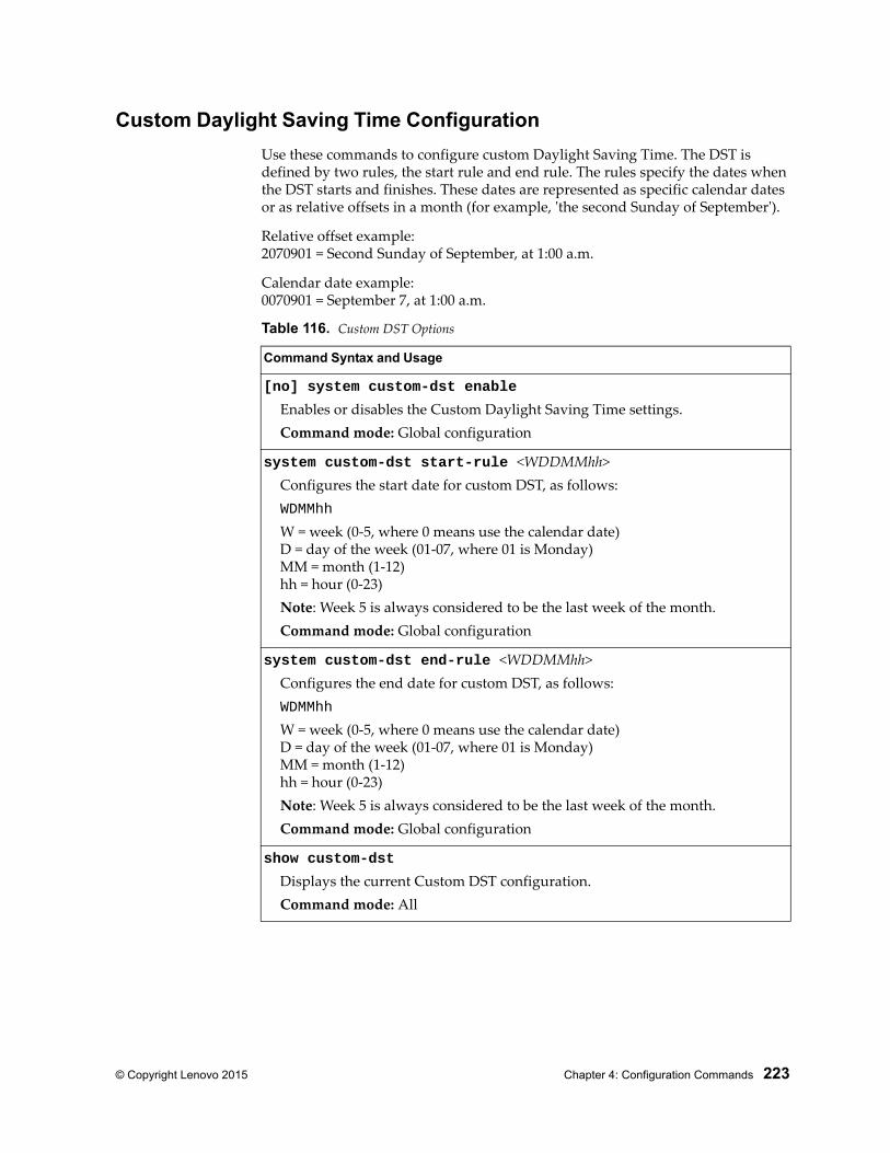
© Copyright Lenovo 2015 Chapter 4: Configuration Commands 223
Custom Daylight Saving Time Configuration
Use these commands to configure custom Daylight Saving Time. The DST is defined by two rules, the start rule and end rule. The rules specify the dates when the DST starts and finishes. These dates are represented as specific calendar dates or as relative offsets in a month (for example, 'the second Sunday of September').
Relative offset example:2070901 = Second Sunday of September, at 1:00 a.m.
Calendar date example:0070901 = September 7, at 1:00 a.m.
Table 116. Custom DST Options
Command Syntax and Usage
[no] system custom-dst enable
Enables or disables the Custom Daylight Saving Time settings.Command mode: Global configuration
system custom-dst start-rule <WDDMMhh>Configures the start date for custom DST, as follows:WDMMhh
W = week (0-5, where 0 means use the calendar date)D = day of the week (01-07, where 01 is Monday)MM = month (1-12)hh = hour (0-23)Note: Week 5 is always considered to be the last week of the month.Command mode: Global configuration
system custom-dst end-rule <WDDMMhh>Configures the end date for custom DST, as follows:WDMMhh
W = week (0-5, where 0 means use the calendar date)D = day of the week (01-07, where 01 is Monday)MM = month (1-12)hh = hour (0-23)Note: Week 5 is always considered to be the last week of the month.Command mode: Global configuration
show custom-dst
Displays the current Custom DST configuration.Command mode: All
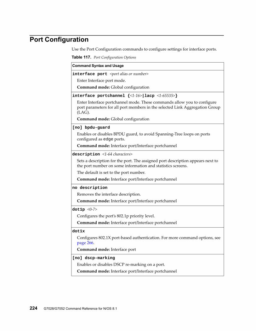
224 G7028/G7052 Command Reference for N/OS 8.1
Port ConfigurationUse the Port Configuration commands to configure settings for interface ports.
Table 117. Port Configuration Options
Command Syntax and Usage
interface port <port alias or number>Enter Interface port mode.Command mode: Global configuration
interface portchannel {<1-16>|lacp <1-65535>}Enter Interface portchannel mode. These commands allow you to configure port parameters for all port members in the selected Link Aggregation Group (LAG).Command mode: Global configuration
[no] bpdu-guard
Enables or disables BPDU guard, to avoid Spanning-Tree loops on ports configured as edge ports.Command mode: Interface port/Interface portchannel
description <1-64 characters>Sets a description for the port. The assigned port description appears next to the port number on some information and statistics screens.The default is set to the port number.Command mode: Interface port/Interface portchannel
no description
Removes the interface description.Command mode: Interface port/Interface portchannel
dot1p <0-7>Configures the port’s 802.1p priority level.Command mode: Interface port/Interface portchannel
dot1x
Configures 802.1X port-based authentication. For more command options, see page 266.Command mode: Interface port
[no] dscp-marking
Enables or disables DSCP re-marking on a port.Command mode: Interface port/Interface portchannel
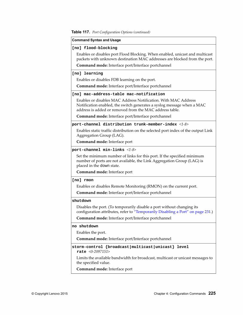
© Copyright Lenovo 2015 Chapter 4: Configuration Commands 225
[no] flood-blocking
Enables or disables port Flood Blocking. When enabled, unicast and multicast packets with unknown destination MAC addresses are blocked from the port.Command mode: Interface port/Interface portchannel
[no] learning
Enables or disables FDB learning on the port.Command mode: Interface port/Interface portchannel
[no] mac-address-table mac-notification
Enables or disables MAC Address Notification. With MAC Address Notification enabled, the switch generates a syslog message when a MAC address is added or removed from the MAC address table.Command mode: Interface port/Interface portchannel
port-channel distribution trunk-member-index <1-8>Enables static traffic distribution on the selected port index of the output Link Aggregation Group (LAG).Command mode: Interface port
port-channel min-links <1-8>Set the minimum number of links for this port. If the specified minimum number of ports are not available, the Link Aggregation Group (LAG) is placed in the down state.Command mode: Interface port
[no] rmon
Enables or disables Remote Monitoring (RMON) on the current port.Command mode: Interface port/Interface portchannel
shutdown
Disables the port. (To temporarily disable a port without changing its configuration attributes, refer to “Temporarily Disabling a Port” on page 231.)Command mode: Interface port/Interface portchannel
no shutdown
Enables the port.Command mode: Interface port/Interface portchannel
storm-control {broadcast|multicast|unicast} level rate <0-2097151>
Limits the available bandwidth for broadcast, multicast or unicast messages to the specified value.Command mode: Interface port
Table 117. Port Configuration Options (continued)
Command Syntax and Usage
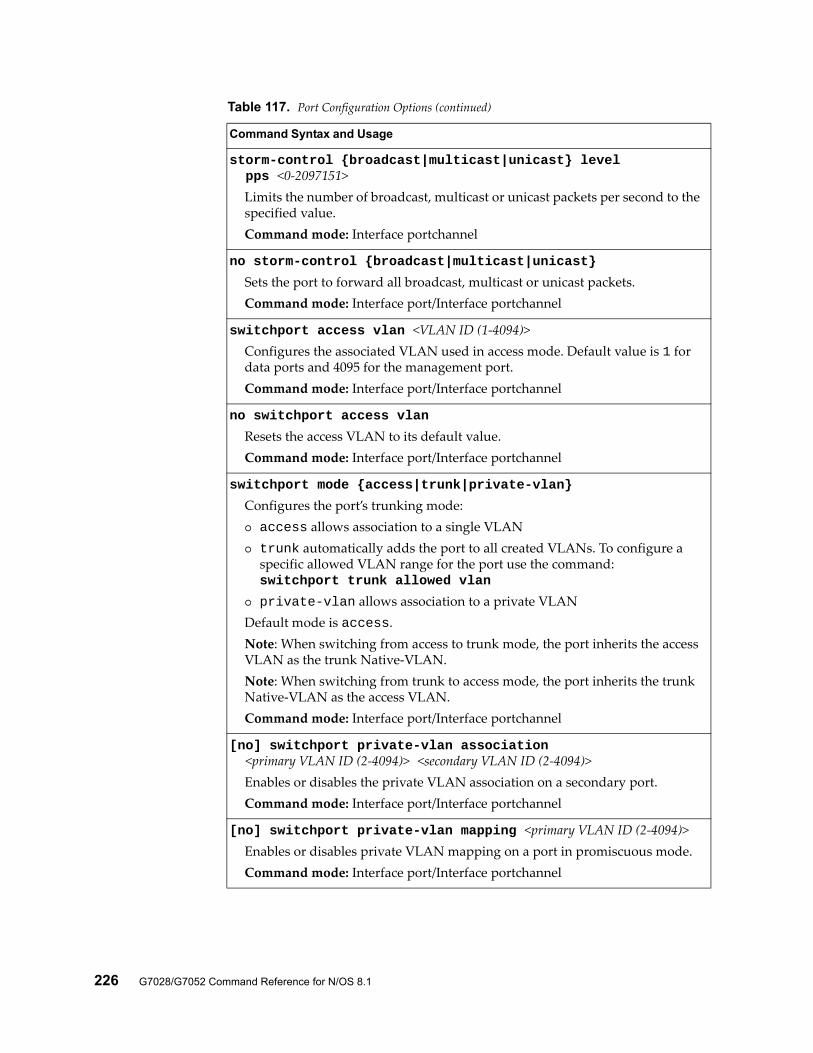
226 G7028/G7052 Command Reference for N/OS 8.1
storm-control {broadcast|multicast|unicast} level pps <0-2097151>
Limits the number of broadcast, multicast or unicast packets per second to the specified value.Command mode: Interface portchannel
no storm-control {broadcast|multicast|unicast}
Sets the port to forward all broadcast, multicast or unicast packets.Command mode: Interface port/Interface portchannel
switchport access vlan <VLAN ID (1-4094)>Configures the associated VLAN used in access mode. Default value is 1 for data ports and 4095 for the management port.Command mode: Interface port/Interface portchannel
no switchport access vlan
Resets the access VLAN to its default value.Command mode: Interface port/Interface portchannel
switchport mode {access|trunk|private-vlan}
Configures the port’s trunking mode: access allows association to a single VLAN trunk automatically adds the port to all created VLANs. To configure a
specific allowed VLAN range for the port use the command:switchport trunk allowed vlan
private-vlan allows association to a private VLANDefault mode is access.Note: When switching from access to trunk mode, the port inherits the access VLAN as the trunk Native-VLAN.Note: When switching from trunk to access mode, the port inherits the trunk Native-VLAN as the access VLAN.Command mode: Interface port/Interface portchannel
[no] switchport private-vlan association <primary VLAN ID (2-4094)> <secondary VLAN ID (2-4094)>
Enables or disables the private VLAN association on a secondary port.Command mode: Interface port/Interface portchannel
[no] switchport private-vlan mapping <primary VLAN ID (2-4094)>Enables or disables private VLAN mapping on a port in promiscuous mode.Command mode: Interface port/Interface portchannel
Table 117. Port Configuration Options (continued)
Command Syntax and Usage
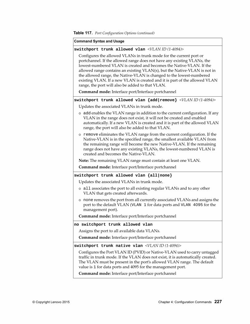
© Copyright Lenovo 2015 Chapter 4: Configuration Commands 227
switchport trunk allowed vlan <VLAN ID (1-4094)>Configures the allowed VLANs in trunk mode for the current port or portchannel. If the allowed range does not have any existing VLANs, the lowest-numbered VLAN is created and becomes the Native-VLAN. If the allowed range contains an existing VLAN(s), but the Native-VLAN is not in the allowed range, the Native-VLAN is changed to the lowest-numbered existing VLAN. If a new VLAN is created and it is part of the allowed VLAN range, the port will also be added to that VLAN.Command mode: Interface port/Interface portchannel
switchport trunk allowed vlan {add|remove} <VLAN ID (1-4094)>Updates the associated VLANs in trunk mode. add enables the VLAN range in addition to the current configuration. If any
VLAN in the range does not exist, it will not be created and enabled automatically. If a new VLAN is created and it is part of the allowed VLAN range, the port will also be added to that VLAN.
remove eliminates the VLAN range from the current configuration. If the Native-VLAN is in the specified range, the smallest available VLAN from the remaining range will become the new Native-VLAN. If the remaining range does not have any existing VLANs, the lowest-numbered VLAN is created and becomes the Native-VLAN.
Note: The remaining VLAN range must contain at least one VLAN.Command mode: Interface port/Interface portchannel
switchport trunk allowed vlan {all|none}
Updates the associated VLANs in trunk mode. all associates the port to all existing regular VLANs and to any other
VLAN that gets created afterwards. none removes the port from all currently associated VLANs and assigns the
port to the default VLAN (VLAN 1 for data ports and VLAN 4095 for the management port).
Command mode: Interface port/Interface portchannel
no switchport trunk allowed vlan
Assigns the port to all available data VLANs.Command mode: Interface port/Interface portchannel
switchport trunk native vlan <VLAN ID (1-4094)>Configures the Port VLAN ID (PVID) or Native-VLAN used to carry untagged traffic in trunk mode. If the VLAN does not exist, it is automatically created. The VLAN must be present in the port’s allowed VLAN range. The default value is 1 for data ports and 4095 for the management port.Command mode: Interface port/Interface portchannel
Table 117. Port Configuration Options (continued)
Command Syntax and Usage
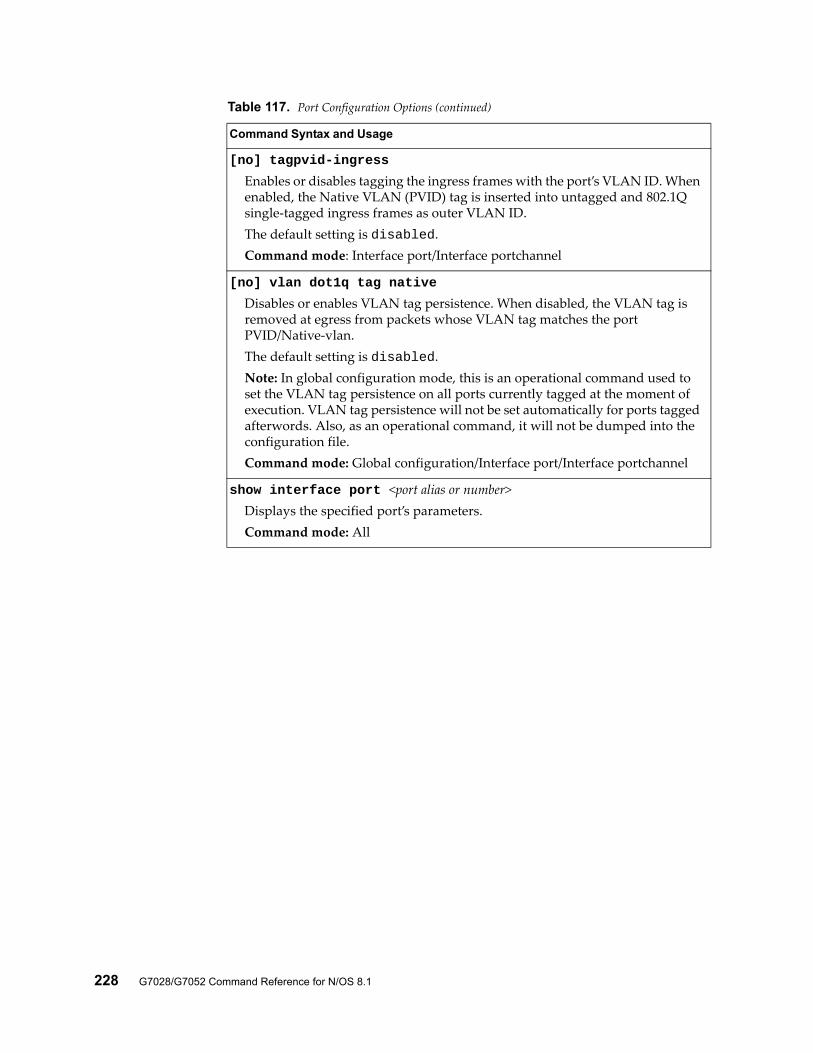
228 G7028/G7052 Command Reference for N/OS 8.1
[no] tagpvid-ingress
Enables or disables tagging the ingress frames with the port’s VLAN ID. When enabled, the Native VLAN (PVID) tag is inserted into untagged and 802.1Q single-tagged ingress frames as outer VLAN ID.The default setting is disabled.Command mode: Interface port/Interface portchannel
[no] vlan dot1q tag native
Disables or enables VLAN tag persistence. When disabled, the VLAN tag is removed at egress from packets whose VLAN tag matches the port PVID/Native-vlan.The default setting is disabled.Note: In global configuration mode, this is an operational command used to set the VLAN tag persistence on all ports currently tagged at the moment of execution. VLAN tag persistence will not be set automatically for ports tagged afterwords. Also, as an operational command, it will not be dumped into the configuration file.Command mode: Global configuration/Interface port/Interface portchannel
show interface port <port alias or number>Displays the specified port’s parameters.Command mode: All
Table 117. Port Configuration Options (continued)
Command Syntax and Usage
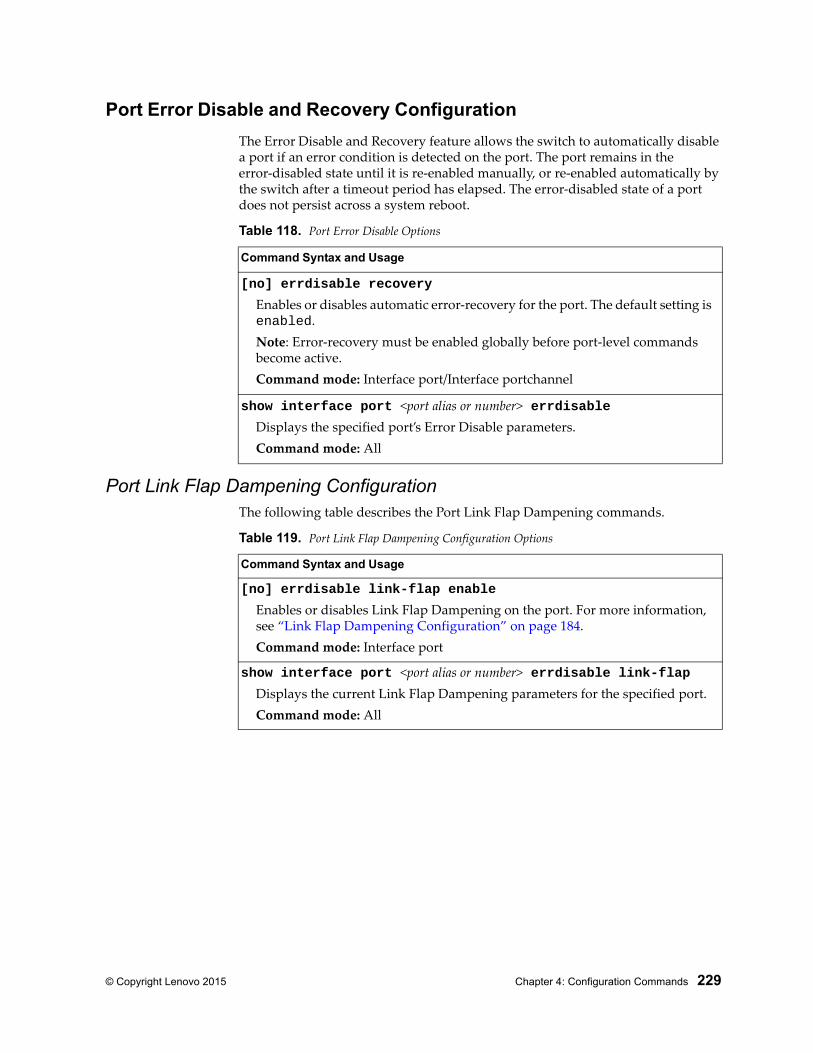
© Copyright Lenovo 2015 Chapter 4: Configuration Commands 229
Port Error Disable and Recovery Configuration
The Error Disable and Recovery feature allows the switch to automatically disable a port if an error condition is detected on the port. The port remains in the error-disabled state until it is re-enabled manually, or re-enabled automatically by the switch after a timeout period has elapsed. The error-disabled state of a port does not persist across a system reboot.
Port Link Flap Dampening ConfigurationThe following table describes the Port Link Flap Dampening commands.
Table 118. Port Error Disable Options
Command Syntax and Usage
[no] errdisable recovery
Enables or disables automatic error-recovery for the port. The default setting is enabled.Note: Error-recovery must be enabled globally before port-level commands become active.Command mode: Interface port/Interface portchannel
show interface port <port alias or number> errdisableDisplays the specified port’s Error Disable parameters.Command mode: All
Table 119. Port Link Flap Dampening Configuration Options
Command Syntax and Usage
[no] errdisable link-flap enable
Enables or disables Link Flap Dampening on the port. For more information, see “Link Flap Dampening Configuration” on page 184.Command mode: Interface port
show interface port <port alias or number> errdisable link-flapDisplays the current Link Flap Dampening parameters for the specified port.Command mode: All
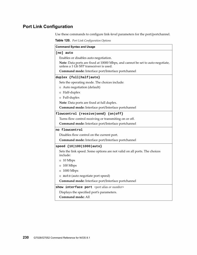
230 G7028/G7052 Command Reference for N/OS 8.1
Port Link Configuration
Use these commands to configure link-level parameters for the port/portchannel.
Table 120. Port Link Configuration Options
Command Syntax and Usage
[no] auto
Enables or disables auto-negotiation.Note: Data ports are fixed at 10000 Mbps, and cannot be set to auto-negotiate, unless a 1 Gb SFP transceiver is used.Command mode: Interface port/Interface portchannel
duplex {full|half|auto}
Sets the operating mode. The choices include: Auto negotiation (default) Half-duplex Full-duplexNote: Data ports are fixed at full duplex.Command mode: Interface port/Interface portchannel
flowcontrol {receive|send} {on|off}
Turns flow control receiving or transmiting on or off.Command mode: Interface port/Interface portchannel
no flowcontrol
Disables flow control on the current port.Command mode: Interface port/Interface portchannel
speed {10|100|1000|auto}
Sets the link speed. Some options are not valid on all ports. The choices include: 10 Mbps 100 Mbps 1000 Mbps auto (auto negotiate port speed)Command mode: Interface port/Interface portchannel
show interface port <port alias or number>Displays the specified port’s parameters.Command mode: All

© Copyright Lenovo 2015 Chapter 4: Configuration Commands 231
Temporarily Disabling a Port
To temporarily disable a port without changing its stored configuration attributes, enter the following command at any prompt:
Because this configuration sets a temporary state for the port, you do not need to use a save operation. The port state will revert to its original configuration when the RackSwitch G7028/G7052 is rebooted. See the “Operations Commands” on page 339 for other operations-level commands.
RS G7052(config)# interface port <port alias or number> shutdown
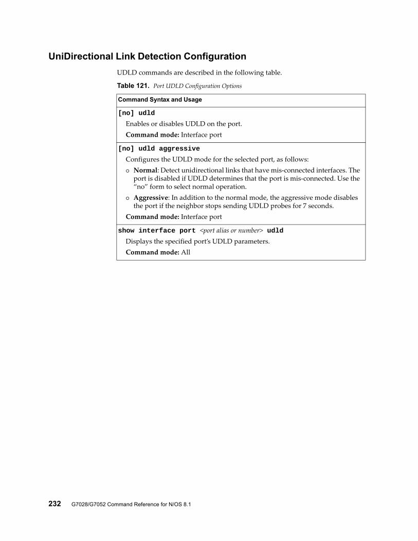
232 G7028/G7052 Command Reference for N/OS 8.1
UniDirectional Link Detection Configuration
UDLD commands are described in the following table.
Table 121. Port UDLD Configuration Options
Command Syntax and Usage
[no] udld
Enables or disables UDLD on the port.Command mode: Interface port
[no] udld aggressive
Configures the UDLD mode for the selected port, as follows: Normal: Detect unidirectional links that have mis-connected interfaces. The
port is disabled if UDLD determines that the port is mis-connected. Use the “no” form to select normal operation.
Aggressive: In addition to the normal mode, the aggressive mode disables the port if the neighbor stops sending UDLD probes for 7 seconds.
Command mode: Interface port
show interface port <port alias or number> udldDisplays the specified port’s UDLD parameters.Command mode: All
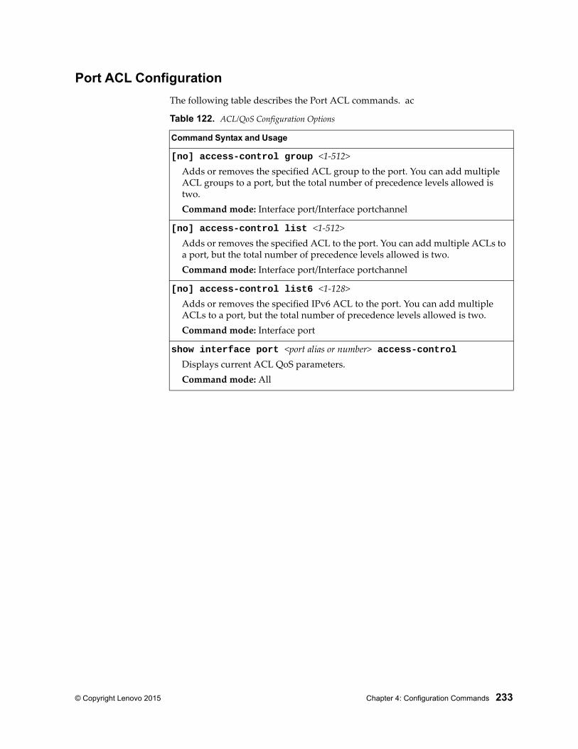
© Copyright Lenovo 2015 Chapter 4: Configuration Commands 233
Port ACL Configuration
The following table describes the Port ACL commands. ac
Table 122. ACL/QoS Configuration Options
Command Syntax and Usage
[no] access-control group <1-512>Adds or removes the specified ACL group to the port. You can add multiple ACL groups to a port, but the total number of precedence levels allowed is two.Command mode: Interface port/Interface portchannel
[no] access-control list <1-512>Adds or removes the specified ACL to the port. You can add multiple ACLs to a port, but the total number of precedence levels allowed is two.Command mode: Interface port/Interface portchannel
[no] access-control list6 <1-128>Adds or removes the specified IPv6 ACL to the port. You can add multiple ACLs to a port, but the total number of precedence levels allowed is two.Command mode: Interface port
show interface port <port alias or number> access-controlDisplays current ACL QoS parameters.Command mode: All
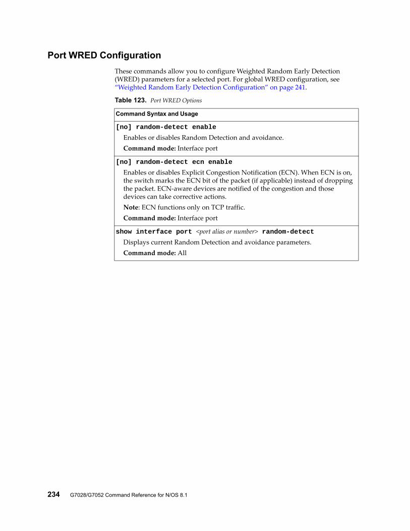
234 G7028/G7052 Command Reference for N/OS 8.1
Port WRED Configuration
These commands allow you to configure Weighted Random Early Detection (WRED) parameters for a selected port. For global WRED configuration, see “Weighted Random Early Detection Configuration” on page 241.
Table 123. Port WRED Options
Command Syntax and Usage
[no] random-detect enable
Enables or disables Random Detection and avoidance.Command mode: Interface port
[no] random-detect ecn enable
Enables or disables Explicit Congestion Notification (ECN). When ECN is on, the switch marks the ECN bit of the packet (if applicable) instead of dropping the packet. ECN-aware devices are notified of the congestion and those devices can take corrective actions.Note: ECN functions only on TCP traffic.Command mode: Interface port
show interface port <port alias or number> random-detectDisplays current Random Detection and avoidance parameters.Command mode: All
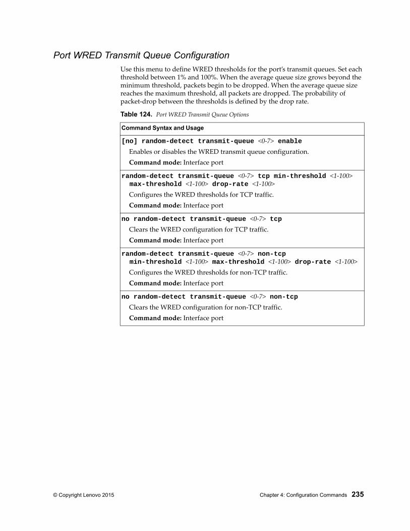
© Copyright Lenovo 2015 Chapter 4: Configuration Commands 235
Port WRED Transmit Queue ConfigurationUse this menu to define WRED thresholds for the port’s transmit queues. Set each threshold between 1% and 100%. When the average queue size grows beyond the minimum threshold, packets begin to be dropped. When the average queue size reaches the maximum threshold, all packets are dropped. The probability of packet-drop between the thresholds is defined by the drop rate.
Table 124. Port WRED Transmit Queue Options
Command Syntax and Usage
[no] random-detect transmit-queue <0-7> enableEnables or disables the WRED transmit queue configuration.Command mode: Interface port
random-detect transmit-queue <0-7> tcp min-threshold <1-100> max-threshold <1-100> drop-rate <1-100>
Configures the WRED thresholds for TCP traffic.Command mode: Interface port
no random-detect transmit-queue <0-7> tcpClears the WRED configuration for TCP traffic.Command mode: Interface port
random-detect transmit-queue <0-7> non-tcp min-threshold <1-100> max-threshold <1-100> drop-rate <1-100>
Configures the WRED thresholds for non-TCP traffic.Command mode: Interface port
no random-detect transmit-queue <0-7> non-tcpClears the WRED configuration for non-TCP traffic.Command mode: Interface port
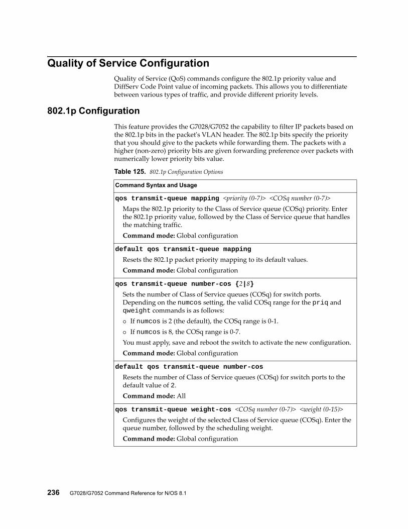
236 G7028/G7052 Command Reference for N/OS 8.1
Quality of Service ConfigurationQuality of Service (QoS) commands configure the 802.1p priority value and DiffServ Code Point value of incoming packets. This allows you to differentiate between various types of traffic, and provide different priority levels.
802.1p Configuration
This feature provides the G7028/G7052 the capability to filter IP packets based on the 802.1p bits in the packet's VLAN header. The 802.1p bits specify the priority that you should give to the packets while forwarding them. The packets with a higher (non-zero) priority bits are given forwarding preference over packets with numerically lower priority bits value.
Table 125. 802.1p Configuration Options
Command Syntax and Usage
qos transmit-queue mapping <priority (0-7)> <COSq number (0-7)>Maps the 802.1p priority to the Class of Service queue (COSq) priority. Enter the 802.1p priority value, followed by the Class of Service queue that handles the matching traffic.Command mode: Global configuration
default qos transmit-queue mapping
Resets the 802.1p packet priority mapping to its default values.Command mode: Global configuration
qos transmit-queue number-cos {2|8}Sets the number of Class of Service queues (COSq) for switch ports. Depending on the numcos setting, the valid COSq range for the priq and qweight commands is as follows: If numcos is 2 (the default), the COSq range is 0-1. If numcos is 8, the COSq range is 0-7.You must apply, save and reboot the switch to activate the new configuration.Command mode: Global configuration
default qos transmit-queue number-cos
Resets the number of Class of Service queues (COSq) for switch ports to the default value of 2.Command mode: All
qos transmit-queue weight-cos <COSq number (0-7)> <weight (0-15)>Configures the weight of the selected Class of Service queue (COSq). Enter the queue number, followed by the scheduling weight.Command mode: Global configuration
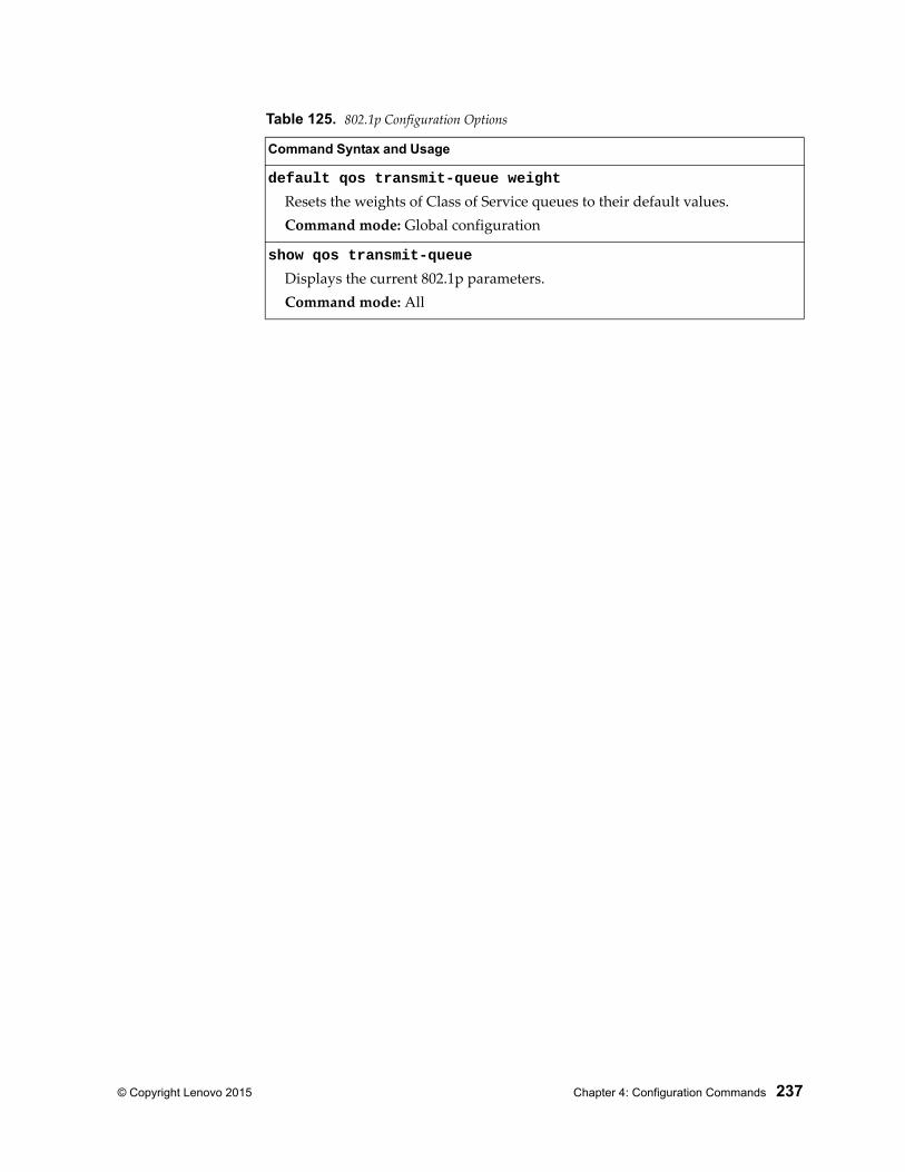
© Copyright Lenovo 2015 Chapter 4: Configuration Commands 237
default qos transmit-queue weight
Resets the weights of Class of Service queues to their default values.Command mode: Global configuration
show qos transmit-queue
Displays the current 802.1p parameters.Command mode: All
Table 125. 802.1p Configuration Options
Command Syntax and Usage
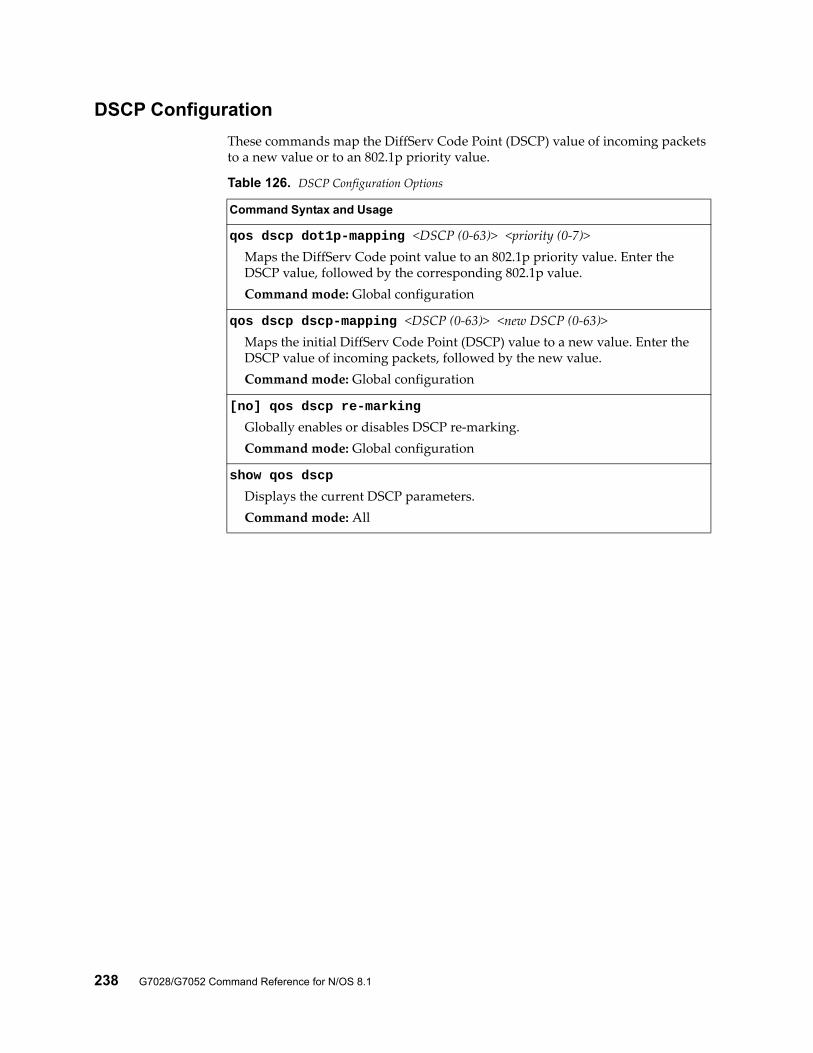
238 G7028/G7052 Command Reference for N/OS 8.1
DSCP Configuration
These commands map the DiffServ Code Point (DSCP) value of incoming packets to a new value or to an 802.1p priority value.
Table 126. DSCP Configuration Options
Command Syntax and Usage
qos dscp dot1p-mapping <DSCP (0-63)> <priority (0-7)>Maps the DiffServ Code point value to an 802.1p priority value. Enter the DSCP value, followed by the corresponding 802.1p value.Command mode: Global configuration
qos dscp dscp-mapping <DSCP (0-63)> <new DSCP (0-63)>Maps the initial DiffServ Code Point (DSCP) value to a new value. Enter the DSCP value of incoming packets, followed by the new value.Command mode: Global configuration
[no] qos dscp re-marking
Globally enables or disables DSCP re-marking.Command mode: Global configuration
show qos dscp
Displays the current DSCP parameters.Command mode: All
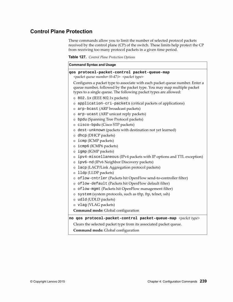
© Copyright Lenovo 2015 Chapter 4: Configuration Commands 239
Control Plane Protection
These commands allow you to limit the number of selected protocol packets received by the control plane (CP) of the switch. These limits help protect the CP from receiving too many protocol packets in a given time period.
Table 127. Control Plane Protection Options
Command Syntax and Usage
qos protocol-packet-control packet-queue-map <packet queue number (0-47)> <packet type>
Configures a packet type to associate with each packet queue number. Enter a queue number, followed by the packet type. You may map multiple packet types to a single queue. The following packet types are allowed: 802.1x (IEEE 802.1x packets) application-cri-packets (critical packets of applications) arp-bcast (ARP broadcast packets) arp-ucast (ARP unicast reply packets) bpdu (Spanning Tree Protocol packets) cisco-bpdu (Cisco STP packets) dest-unknown (packets with destination not yet learned) dhcp (DHCP packets) icmp (ICMP packets) icmp6 (ICMP6 packets) igmp (IGMP packets) ipv4-miscellaneous (IPv4 packets with IP options and TTL exception) ipv6-nd (IPv6 Neighbor Discovery packets) lacp (LACP/Link Aggregation protocol packets) lldp (LLDP packets) oflow-cntrler (Packets hit OpenFlow send-to-controller filter) oflow-default (Packets hit OpenFlow default filter) oflow-mgmt (Packets hit OpenFlow management filter) system (system protocols, such as tftp, ftp, telnet, ssh) udld (UDLD packets) vlag (VLAG packets)Command mode: Global configuration
no qos protocol-packet-control packet-queue-map <packet type>Clears the selected packet type from its associated packet queue.Command mode: Global configuration
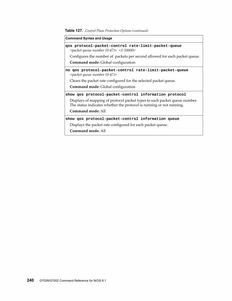
240 G7028/G7052 Command Reference for N/OS 8.1
qos protocol-packet-control rate-limit-packet-queue <packet queue number (0-47)> <1-10000>
Configures the number of packets per second allowed for each packet queue.Command mode: Global configuration
no qos protocol-packet-control rate-limit-packet-queue <packet queue number (0-47)>
Clears the packet rate configured for the selected packet queue.Command mode: Global configuration
show qos protocol-packet-control information protocol
Displays of mapping of protocol packet types to each packet queue number. The status indicates whether the protocol is running or not running.Command mode: All
show qos protocol-packet-control information queue
Displays the packet rate configured for each packet queue.Command mode: All
Table 127. Control Plane Protection Options (continued)
Command Syntax and Usage
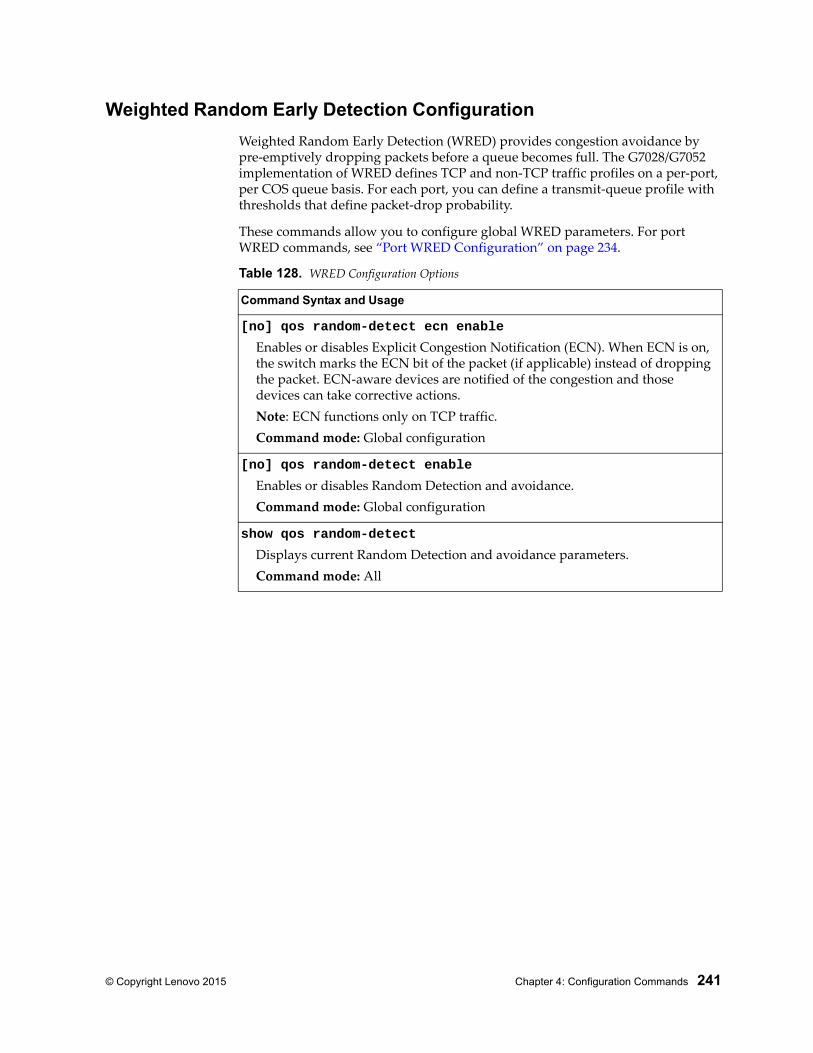
© Copyright Lenovo 2015 Chapter 4: Configuration Commands 241
Weighted Random Early Detection Configuration
Weighted Random Early Detection (WRED) provides congestion avoidance by pre-emptively dropping packets before a queue becomes full. The G7028/G7052 implementation of WRED defines TCP and non-TCP traffic profiles on a per-port, per COS queue basis. For each port, you can define a transmit-queue profile with thresholds that define packet-drop probability.
These commands allow you to configure global WRED parameters. For port WRED commands, see “Port WRED Configuration” on page 234.
Table 128. WRED Configuration Options
Command Syntax and Usage
[no] qos random-detect ecn enable
Enables or disables Explicit Congestion Notification (ECN). When ECN is on, the switch marks the ECN bit of the packet (if applicable) instead of dropping the packet. ECN-aware devices are notified of the congestion and those devices can take corrective actions.Note: ECN functions only on TCP traffic.Command mode: Global configuration
[no] qos random-detect enable
Enables or disables Random Detection and avoidance.Command mode: Global configuration
show qos random-detect
Displays current Random Detection and avoidance parameters.Command mode: All
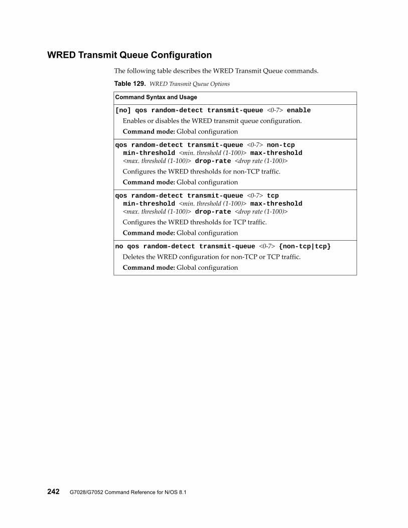
242 G7028/G7052 Command Reference for N/OS 8.1
WRED Transmit Queue Configuration
The following table describes the WRED Transmit Queue commands.
Table 129. WRED Transmit Queue Options
Command Syntax and Usage
[no] qos random-detect transmit-queue <0-7> enableEnables or disables the WRED transmit queue configuration.Command mode: Global configuration
qos random-detect transmit-queue <0-7> non-tcp min-threshold <min. threshold (1-100)> max-threshold <max. threshold (1-100)> drop-rate <drop rate (1-100)>
Configures the WRED thresholds for non-TCP traffic.Command mode: Global configuration
qos random-detect transmit-queue <0-7> tcp min-threshold <min. threshold (1-100)> max-threshold <max. threshold (1-100)> drop-rate <drop rate (1-100)>
Configures the WRED thresholds for TCP traffic.Command mode: Global configuration
no qos random-detect transmit-queue <0-7> {non-tcp|tcp}Deletes the WRED configuration for non-TCP or TCP traffic.Command mode: Global configuration
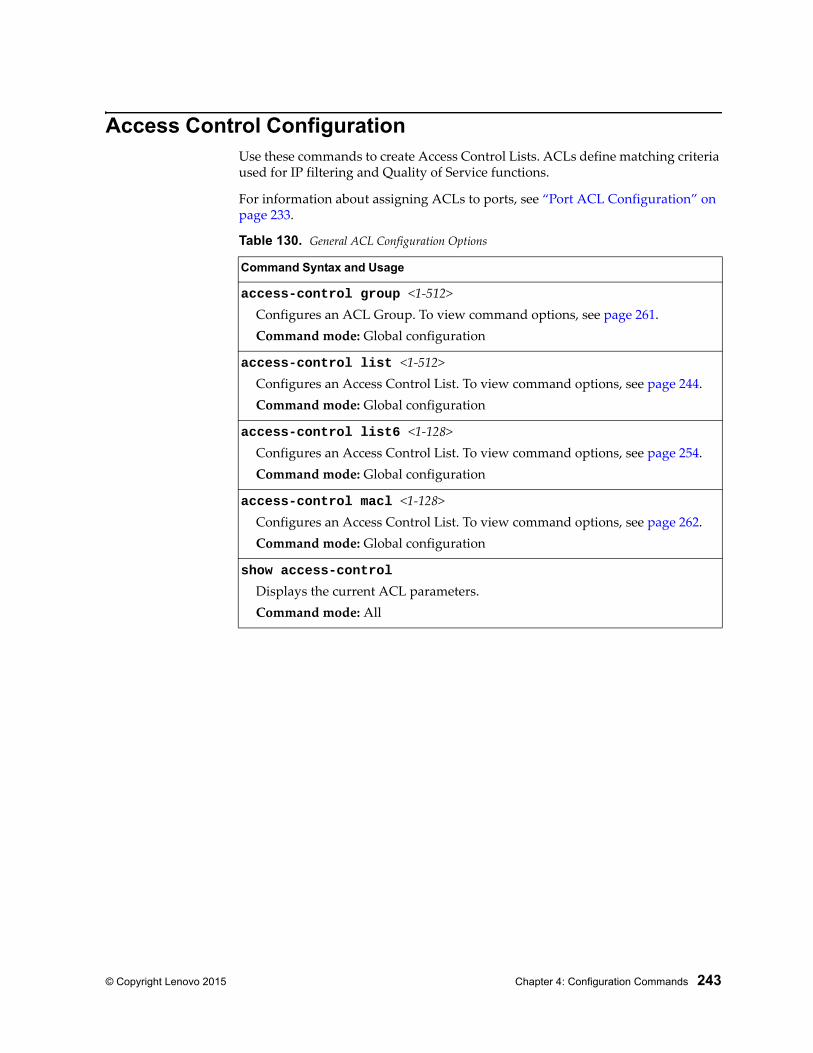
© Copyright Lenovo 2015 Chapter 4: Configuration Commands 243
Access Control ConfigurationUse these commands to create Access Control Lists. ACLs define matching criteria used for IP filtering and Quality of Service functions.
For information about assigning ACLs to ports, see “Port ACL Configuration” on page 233.
Table 130. General ACL Configuration Options
Command Syntax and Usage
access-control group <1-512>Configures an ACL Group. To view command options, see page 261.Command mode: Global configuration
access-control list <1-512>Configures an Access Control List. To view command options, see page 244.Command mode: Global configuration
access-control list6 <1-128>Configures an Access Control List. To view command options, see page 254.Command mode: Global configuration
access-control macl <1-128> Configures an Access Control List. To view command options, see page 262.Command mode: Global configuration
show access-control
Displays the current ACL parameters.Command mode: All
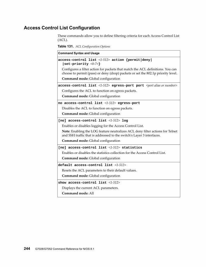
244 G7028/G7052 Command Reference for N/OS 8.1
Access Control List Configuration
These commands allow you to define filtering criteria for each Access Control List (ACL).
Table 131. ACL Configuration Options
Command Syntax and Usage
access-control list <1-512> action {permit|deny| |set-priority <0-7>}
Configures a filter action for packets that match the ACL definitions. You can choose to permit (pass) or deny (drop) packets or set the 802.1p priority level.Command mode: Global configuration
access-control list <1-512> egress-port port <port alias or number>Configures the ACL to function on egress packets.Command mode: Global configuration
no access-control list <1-512> egress-portDisables the ACL to function on egress packets.Command mode: Global configuration
[no] access-control list <1-512> logEnables or disables logging for the Access Control List.Note: Enabling the LOG feature neutralizes ACL deny filter actions for Telnet and SSH traffic that is addressed to the switch's Layer 3 interfaces.Command mode: Global configuration
[no] access-control list <1-512> statisticsEnables or disables the statistics collection for the Access Control List.Command mode: Global configuration
default access-control list <1-512>Resets the ACL parameters to their default values.Command mode: Global configuration
show access-control list <1-512>Displays the current ACL parameters.Command mode: All
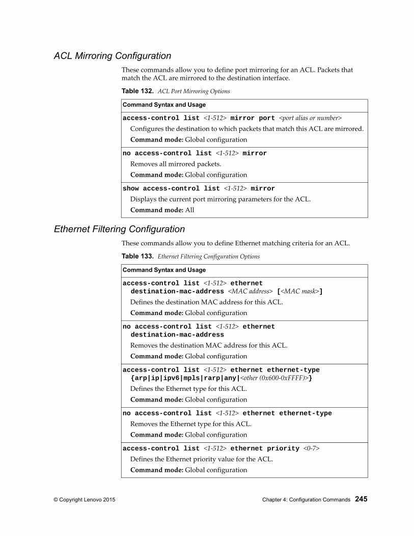
© Copyright Lenovo 2015 Chapter 4: Configuration Commands 245
ACL Mirroring ConfigurationThese commands allow you to define port mirroring for an ACL. Packets that match the ACL are mirrored to the destination interface.
Ethernet Filtering ConfigurationThese commands allow you to define Ethernet matching criteria for an ACL.
Table 132. ACL Port Mirroring Options
Command Syntax and Usage
access-control list <1-512> mirror port <port alias or number>Configures the destination to which packets that match this ACL are mirrored.Command mode: Global configuration
no access-control list <1-512> mirrorRemoves all mirrored packets.Command mode: Global configuration
show access-control list <1-512> mirrorDisplays the current port mirroring parameters for the ACL.Command mode: All
Table 133. Ethernet Filtering Configuration Options
Command Syntax and Usage
access-control list <1-512> ethernet destination-mac-address <MAC address> [<MAC mask>]
Defines the destination MAC address for this ACL.Command mode: Global configuration
no access-control list <1-512> ethernet destination-mac-address
Removes the destination MAC address for this ACL.Command mode: Global configuration
access-control list <1-512> ethernet ethernet-type {arp|ip|ipv6|mpls|rarp|any|<other (0x600-0xFFFF)>}
Defines the Ethernet type for this ACL.Command mode: Global configuration
no access-control list <1-512> ethernet ethernet-typeRemoves the Ethernet type for this ACL.Command mode: Global configuration
access-control list <1-512> ethernet priority <0-7>Defines the Ethernet priority value for the ACL.Command mode: Global configuration
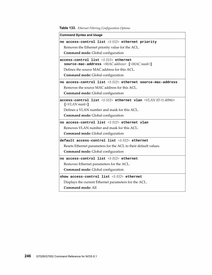
246 G7028/G7052 Command Reference for N/OS 8.1
no access-control list <1-512> ethernet priorityRemoves the Ethernet priority value for the ACL.Command mode: Global configuration
access-control list <1-512> ethernet source-mac-address <MAC address> [<MAC mask>]
Defines the source MAC address for this ACL.Command mode: Global configuration
no access-control list <1-512> ethernet source-mac-addressRemoves the source MAC address for this ACL.Command mode: Global configuration
access-control list <1-512> ethernet vlan <VLAN ID (1-4094)> [<VLAN mask>]
Defines a VLAN number and mask for this ACL.Command mode: Global configuration
no access-control list <1-512> ethernet vlanRemoves VLAN number and mask for this ACL.Command mode: Global configuration
default access-control list <1-512> ethernetResets Ethernet parameters for the ACL to their default values.Command mode: Global configuration
no access-control list <1-512> ethernetRemoves Ethernet parameters for the ACL.Command mode: Global configuration
show access-control list <1-512> ethernetDisplays the current Ethernet parameters for the ACL.Command mode: All
Table 133. Ethernet Filtering Configuration Options
Command Syntax and Usage
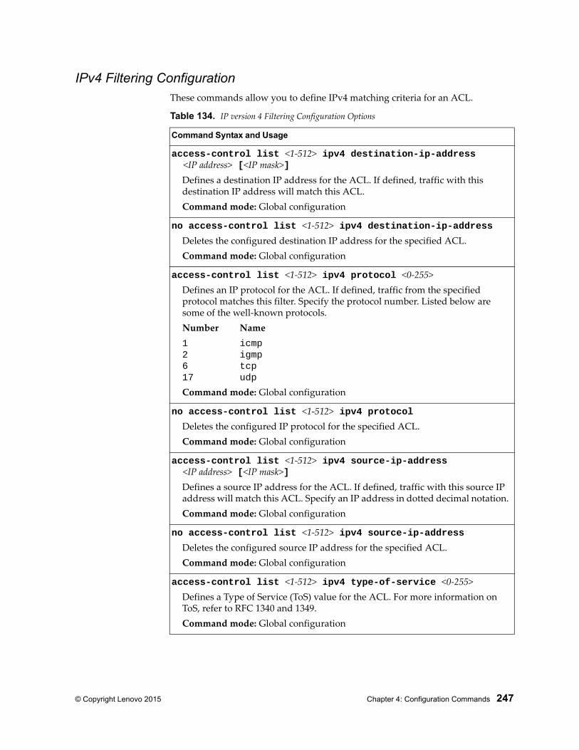
© Copyright Lenovo 2015 Chapter 4: Configuration Commands 247
IPv4 Filtering ConfigurationThese commands allow you to define IPv4 matching criteria for an ACL.
Table 134. IP version 4 Filtering Configuration Options
Command Syntax and Usage
access-control list <1-512> ipv4 destination-ip-address <IP address> [<IP mask>]
Defines a destination IP address for the ACL. If defined, traffic with this destination IP address will match this ACL.Command mode: Global configuration
no access-control list <1-512> ipv4 destination-ip-addressDeletes the configured destination IP address for the specified ACL.Command mode: Global configuration
access-control list <1-512> ipv4 protocol <0-255>Defines an IP protocol for the ACL. If defined, traffic from the specified protocol matches this filter. Specify the protocol number. Listed below are some of the well-known protocols.Number Name1 icmp2 igmp6 tcp17 udp
Command mode: Global configuration
no access-control list <1-512> ipv4 protocolDeletes the configured IP protocol for the specified ACL.Command mode: Global configuration
access-control list <1-512> ipv4 source-ip-address <IP address> [<IP mask>]
Defines a source IP address for the ACL. If defined, traffic with this source IP address will match this ACL. Specify an IP address in dotted decimal notation.Command mode: Global configuration
no access-control list <1-512> ipv4 source-ip-addressDeletes the configured source IP address for the specified ACL.Command mode: Global configuration
access-control list <1-512> ipv4 type-of-service <0-255>Defines a Type of Service (ToS) value for the ACL. For more information on ToS, refer to RFC 1340 and 1349.Command mode: Global configuration
248 G7028/G7052 Command Reference for N/OS 8.1
TCP/UDP Filtering ConfigurationThese commands allow you to define TCP/UDP matching criteria for an ACL.
no access-control list <1-512> ipv4 type-of-serviceDeletes the configured Type of Service (ToS) value for the specified ACL.Command mode: Global configuration
default access-control list <1-512> ipv4Resets the IPv4 parameters for the ACL to their default values.Command mode: Global configuration
show access-control list <1-512> ipv4Displays the current IPv4 parameters.Command mode: All
Table 134. IP version 4 Filtering Configuration Options
Command Syntax and Usage
Table 135. TCP/UDP Filtering Configuration Options
Command Syntax and Usage
access-control list <1-512> tcp-udp source-port <1-65535> [<mask (0xFFFF)>]
Defines a source port for the ACL. If defined, traffic with the specified TCP or UDP source port will match this ACL. Specify the port number. Listed here are some of the well-known ports:Number Name20 ftp-data21 ftp22 ssh23 telnet25 smtp37 time42 name43 whois53 domain69 tftp70 gopher79 finger80 http
Command mode: Global configuration
no access-control list <1-512> tcp-udp source-portDisables the configured source port for the specified ACL.Command mode: Global configuration
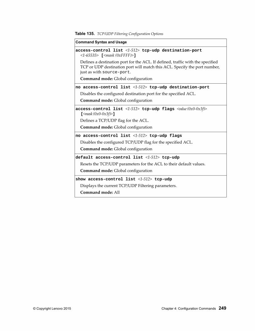
© Copyright Lenovo 2015 Chapter 4: Configuration Commands 249
access-control list <1-512> tcp-udp destination-port <1-65535> [<mask (0xFFFF)>]
Defines a destination port for the ACL. If defined, traffic with the specified TCP or UDP destination port will match this ACL. Specify the port number, just as with source-port.Command mode: Global configuration
no access-control list <1-512> tcp-udp destination-portDisables the configured destination port for the specified ACL.Command mode: Global configuration
access-control list <1-512> tcp-udp flags <value (0x0-0x3f)> [<mask (0x0-0x3f)>]
Defines a TCP/UDP flag for the ACL.Command mode: Global configuration
no access-control list <1-512> tcp-udp flagsDisables the configured TCP/UDP flag for the specified ACL.Command mode: Global configuration
default access-control list <1-512> tcp-udpResets the TCP/UDP parameters for the ACL to their default values.Command mode: Global configuration
show access-control list <1-512> tcp-udpDisplays the current TCP/UDP Filtering parameters.Command mode: All
Table 135. TCP/UDP Filtering Configuration Options
Command Syntax and Usage
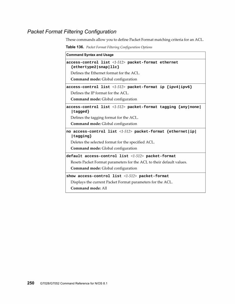
250 G7028/G7052 Command Reference for N/OS 8.1
Packet Format Filtering ConfigurationThese commands allow you to define Packet Format matching criteria for an ACL.
Table 136. Packet Format Filtering Configuration Options
Command Syntax and Usage
access-control list <1-512> packet-format ethernet {ethertype2|snap|llc}
Defines the Ethernet format for the ACL.Command mode: Global configuration
access-control list <1-512> packet-format ip {ipv4|ipv6}Defines the IP format for the ACL.Command mode: Global configuration
access-control list <1-512> packet-format tagging {any|none| |tagged}
Defines the tagging format for the ACL.Command mode: Global configuration
no access-control list <1-512> packet-format {ethernet|ip| |tagging}
Deletes the selected format for the specified ACL.Command mode: Global configuration
default access-control list <1-512> packet-formatResets Packet Format parameters for the ACL to their default values.Command mode: Global configuration
show access-control list <1-512> packet-formatDisplays the current Packet Format parameters for the ACL.Command mode: All
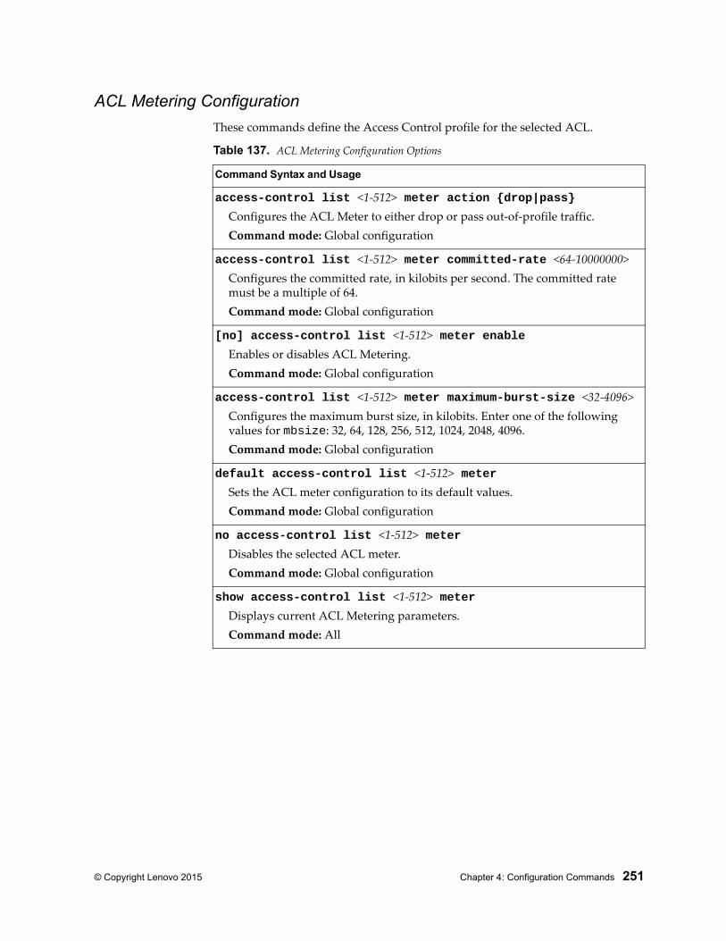
© Copyright Lenovo 2015 Chapter 4: Configuration Commands 251
ACL Metering Configuration
These commands define the Access Control profile for the selected ACL.
Table 137. ACL Metering Configuration Options
Command Syntax and Usage
access-control list <1-512> meter action {drop|pass}Configures the ACL Meter to either drop or pass out-of-profile traffic.Command mode: Global configuration
access-control list <1-512> meter committed-rate <64-10000000>Configures the committed rate, in kilobits per second. The committed rate must be a multiple of 64.Command mode: Global configuration
[no] access-control list <1-512> meter enableEnables or disables ACL Metering.Command mode: Global configuration
access-control list <1-512> meter maximum-burst-size <32-4096>Configures the maximum burst size, in kilobits. Enter one of the following values for mbsize: 32, 64, 128, 256, 512, 1024, 2048, 4096.Command mode: Global configuration
default access-control list <1-512> meterSets the ACL meter configuration to its default values.Command mode: Global configuration
no access-control list <1-512> meterDisables the selected ACL meter.Command mode: Global configuration
show access-control list <1-512> meterDisplays current ACL Metering parameters.Command mode: All
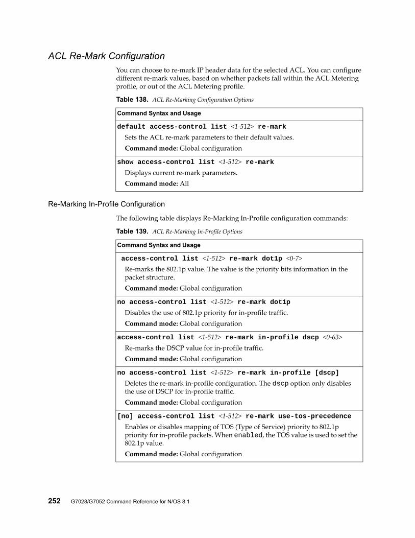
252 G7028/G7052 Command Reference for N/OS 8.1
ACL Re-Mark ConfigurationYou can choose to re-mark IP header data for the selected ACL. You can configure different re-mark values, based on whether packets fall within the ACL Metering profile, or out of the ACL Metering profile.
Re-Marking In-Profile Configuration
The following table displays Re-Marking In-Profile configuration commands:
Table 138. ACL Re-Marking Configuration Options
Command Syntax and Usage
default access-control list <1-512> re-markSets the ACL re-mark parameters to their default values.Command mode: Global configuration
show access-control list <1-512> re-markDisplays current re-mark parameters.Command mode: All
Table 139. ACL Re-Marking In-Profile Options
Command Syntax and Usage
access-control list <1-512> re-mark dot1p <0-7>Re-marks the 802.1p value. The value is the priority bits information in the packet structure.Command mode: Global configuration
no access-control list <1-512> re-mark dot1pDisables the use of 802.1p priority for in-profile traffic.Command mode: Global configuration
access-control list <1-512> re-mark in-profile dscp <0-63>Re-marks the DSCP value for in-profile traffic.Command mode: Global configuration
no access-control list <1-512> re-mark in-profile [dscp]Deletes the re-mark in-profile configuration. The dscp option only disables the use of DSCP for in-profile traffic.Command mode: Global configuration
[no] access-control list <1-512> re-mark use-tos-precedenceEnables or disables mapping of TOS (Type of Service) priority to 802.1p priority for in-profile packets. When enabled, the TOS value is used to set the 802.1p value.Command mode: Global configuration
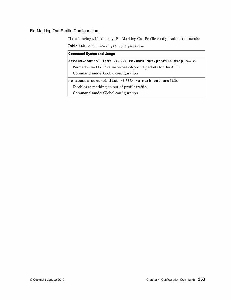
© Copyright Lenovo 2015 Chapter 4: Configuration Commands 253
Re-Marking Out-Profile Configuration
The following table displays Re-Marking Out-Profile configuration commands:
Table 140. ACL Re-Marking Out-of-Profile Options
Command Syntax and Usage
access-control list <1-512> re-mark out-profile dscp <0-63>Re-marks the DSCP value on out-of-profile packets for the ACL.Command mode: Global configuration
no access-control list <1-512> re-mark out-profileDisables re-marking on out-of-profile traffic.Command mode: Global configuration
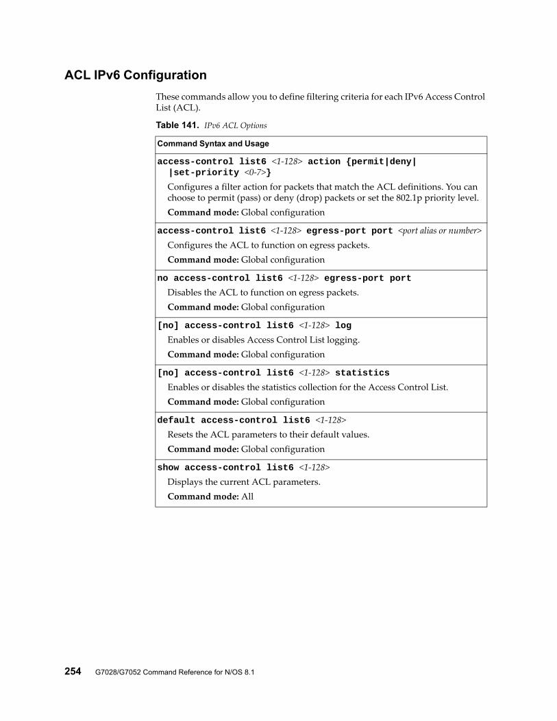
254 G7028/G7052 Command Reference for N/OS 8.1
ACL IPv6 Configuration
These commands allow you to define filtering criteria for each IPv6 Access Control List (ACL).
Table 141. IPv6 ACL Options
Command Syntax and Usage
access-control list6 <1-128> action {permit|deny| |set-priority <0-7>}
Configures a filter action for packets that match the ACL definitions. You can choose to permit (pass) or deny (drop) packets or set the 802.1p priority level.Command mode: Global configuration
access-control list6 <1-128> egress-port port <port alias or number>Configures the ACL to function on egress packets.Command mode: Global configuration
no access-control list6 <1-128> egress-port portDisables the ACL to function on egress packets.Command mode: Global configuration
[no] access-control list6 <1-128> logEnables or disables Access Control List logging.Command mode: Global configuration
[no] access-control list6 <1-128> statisticsEnables or disables the statistics collection for the Access Control List.Command mode: Global configuration
default access-control list6 <1-128>Resets the ACL parameters to their default values.Command mode: Global configuration
show access-control list6 <1-128>Displays the current ACL parameters.Command mode: All
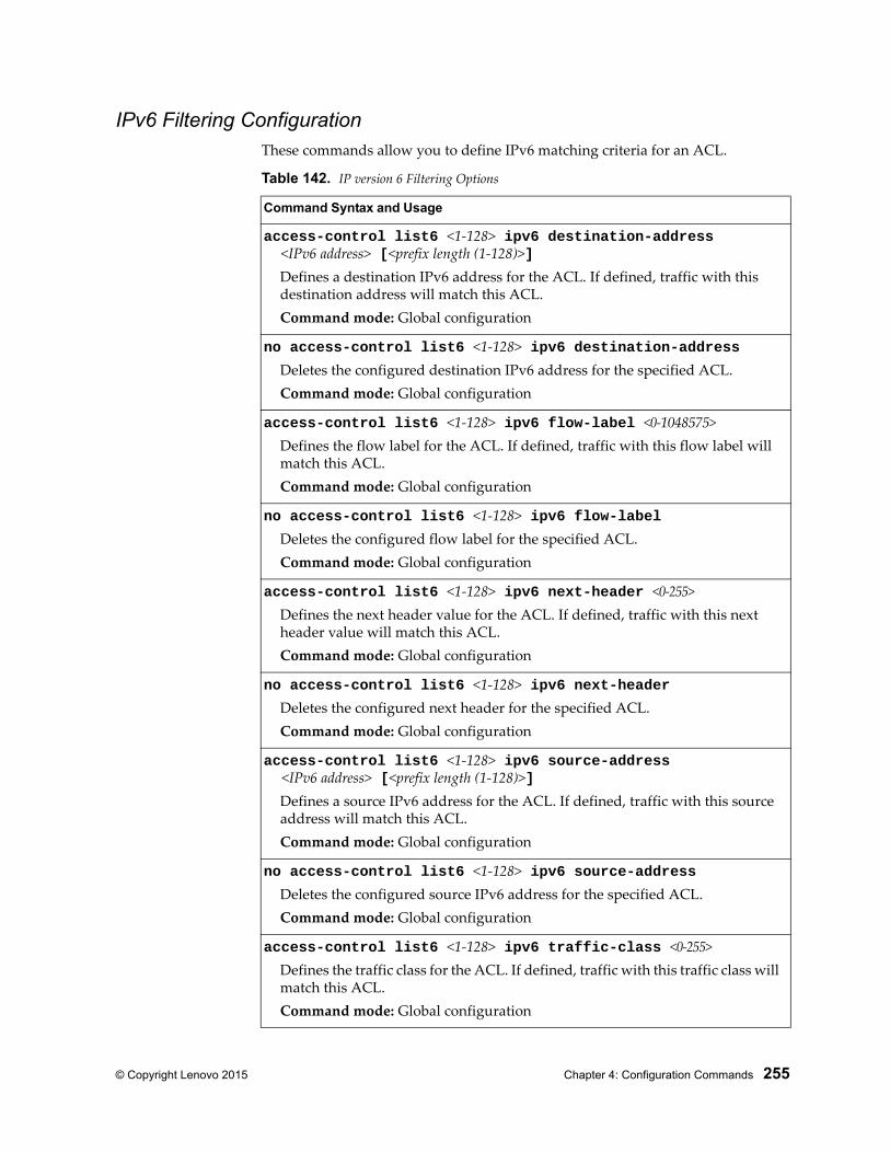
© Copyright Lenovo 2015 Chapter 4: Configuration Commands 255
IPv6 Filtering ConfigurationThese commands allow you to define IPv6 matching criteria for an ACL.
Table 142. IP version 6 Filtering Options
Command Syntax and Usage
access-control list6 <1-128> ipv6 destination-address <IPv6 address> [<prefix length (1-128)>]
Defines a destination IPv6 address for the ACL. If defined, traffic with this destination address will match this ACL.Command mode: Global configuration
no access-control list6 <1-128> ipv6 destination-addressDeletes the configured destination IPv6 address for the specified ACL.Command mode: Global configuration
access-control list6 <1-128> ipv6 flow-label <0-1048575>Defines the flow label for the ACL. If defined, traffic with this flow label will match this ACL.Command mode: Global configuration
no access-control list6 <1-128> ipv6 flow-labelDeletes the configured flow label for the specified ACL.Command mode: Global configuration
access-control list6 <1-128> ipv6 next-header <0-255>Defines the next header value for the ACL. If defined, traffic with this next header value will match this ACL.Command mode: Global configuration
no access-control list6 <1-128> ipv6 next-headerDeletes the configured next header for the specified ACL.Command mode: Global configuration
access-control list6 <1-128> ipv6 source-address <IPv6 address> [<prefix length (1-128)>]
Defines a source IPv6 address for the ACL. If defined, traffic with this source address will match this ACL.Command mode: Global configuration
no access-control list6 <1-128> ipv6 source-addressDeletes the configured source IPv6 address for the specified ACL.Command mode: Global configuration
access-control list6 <1-128> ipv6 traffic-class <0-255>Defines the traffic class for the ACL. If defined, traffic with this traffic class will match this ACL.Command mode: Global configuration
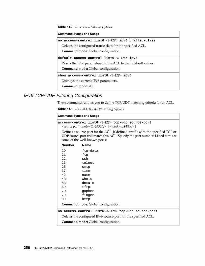
256 G7028/G7052 Command Reference for N/OS 8.1
IPv6 TCP/UDP Filtering Configuration These commands allows you to define TCP/UDP matching criteria for an ACL.
no access-control list6 <1-128> ipv6 traffic-classDeletes the configured traffic class for the specified ACL.Command mode: Global configuration
default access-control list6 <1-128> ipv6Resets the IPv6 parameters for the ACL to their default values.Command mode: Global configuration
show access-control list6 <1-128> ipv6Displays the current IPv6 parameters.Command mode: All
Table 142. IP version 6 Filtering Options
Command Syntax and Usage
Table 143. IPv6 ACL TCP/UDP Filtering Options
Command Syntax and Usage
access-control list6 <1-128> tcp-udp source-port <source port number (1-65535)> [<mask (0xFFFF)>]
Defines a source port for the ACL. If defined, traffic with the specified TCP or UDP source port will match this ACL. Specify the port number. Listed here are some of the well-known ports:Number Name
20 ftp-data21 ftp22 ssh23 telnet25 smtp37 time42 name43 whois53 domain69 tftp70 gopher79 finger80 http
Command mode: Global configuration
no access-control list6 <1-128> tcp-udp source-portDeletes the configured IPv6 source-port for the specified ACL.Command mode: Global configuration
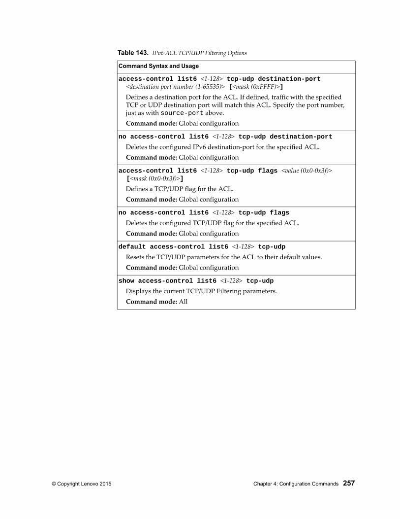
© Copyright Lenovo 2015 Chapter 4: Configuration Commands 257
access-control list6 <1-128> tcp-udp destination-port <destination port number (1-65535)> [<mask (0xFFFF)>]
Defines a destination port for the ACL. If defined, traffic with the specified TCP or UDP destination port will match this ACL. Specify the port number, just as with source-port above.Command mode: Global configuration
no access-control list6 <1-128> tcp-udp destination-portDeletes the configured IPv6 destination-port for the specified ACL.Command mode: Global configuration
access-control list6 <1-128> tcp-udp flags <value (0x0-0x3f)> [<mask (0x0-0x3f)>]
Defines a TCP/UDP flag for the ACL.Command mode: Global configuration
no access-control list6 <1-128> tcp-udp flagsDeletes the configured TCP/UDP flag for the specified ACL.Command mode: Global configuration
default access-control list6 <1-128> tcp-udpResets the TCP/UDP parameters for the ACL to their default values.Command mode: Global configuration
show access-control list6 <1-128> tcp-udpDisplays the current TCP/UDP Filtering parameters.Command mode: All
Table 143. IPv6 ACL TCP/UDP Filtering Options
Command Syntax and Usage

258 G7028/G7052 Command Reference for N/OS 8.1
IPv6 Re-Mark ConfigurationYou can choose to re-mark IP header data for the selected ACL. You can configure different re-mark values, based on whether packets fall within the ACL metering profile, or out of the ACL metering profile.
IPv6 Re-Marking In-Profile Configuration
The following table displays IPv6 Re-Marking In-Profile configuration commands:
Table 144. IPv6 Re-Marking In-Profile Options
Command Syntax and Usage
default access-control list6 <1-128> re-markSets the ACL re-mark parameters to their default values.Command mode: Global configuration
show access-control list6 <1-128> re-markDisplays current re-mark parameters.Command mode: All
Table 145. IPv6 ACL Re-Marking In-Profile Options
Command Syntax and Usage
access-control list6 <1-128> re-mark dot1p <0-7>Re-marks the 802.1p value. The value is the priority bits information in the packet structure.Command mode: Global configuration
no access-control6 list6 <1-128> re-mark dot1pDisables the use of 802.1p priority for in-profile traffic.Command mode: Global configuration
access-control list6 <1-128> re-mark in-profile dscp <0-63>Re-marks the DSCP value for in-profile traffic.Command mode: Global configuration
no access-control list6 <1-128> re-mark in-profile [dscp]Deletes the re-mark in-profile configuration. The dscp option only disables the use of DSCP for in-profile traffic.Command mode: Global configuration
[no] access-control list6 <1-128> re-mark use-tos-precedenceEnables or disables mapping of TOS (Type of Service) priority to 802.1p priority for in-profile packets. When enabled, the TOS value is used to set the 802.1p value.Command mode: Global configuration
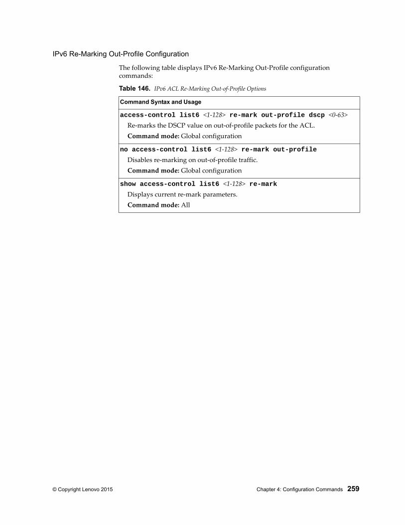
© Copyright Lenovo 2015 Chapter 4: Configuration Commands 259
IPv6 Re-Marking Out-Profile Configuration
The following table displays IPv6 Re-Marking Out-Profile configuration commands:
Table 146. IPv6 ACL Re-Marking Out-of-Profile Options
Command Syntax and Usage
access-control list6 <1-128> re-mark out-profile dscp <0-63>Re-marks the DSCP value on out-of-profile packets for the ACL.Command mode: Global configuration
no access-control list6 <1-128> re-mark out-profileDisables re-marking on out-of-profile traffic.Command mode: Global configuration
show access-control list6 <1-128> re-markDisplays current re-mark parameters.Command mode: All
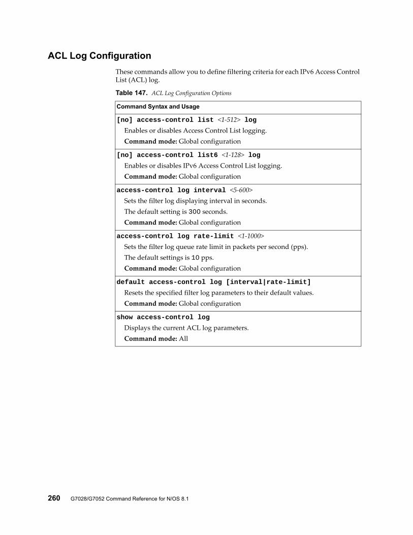
260 G7028/G7052 Command Reference for N/OS 8.1
ACL Log Configuration
These commands allow you to define filtering criteria for each IPv6 Access Control List (ACL) log.
Table 147. ACL Log Configuration Options
Command Syntax and Usage
[no] access-control list <1-512> logEnables or disables Access Control List logging.Command mode: Global configuration
[no] access-control list6 <1-128> logEnables or disables IPv6 Access Control List logging.Command mode: Global configuration
access-control log interval <5-600>Sets the filter log displaying interval in seconds.The default setting is 300 seconds.Command mode: Global configuration
access-control log rate-limit <1-1000>Sets the filter log queue rate limit in packets per second (pps).The default settings is 10 pps.Command mode: Global configuration
default access-control log [interval|rate-limit]
Resets the specified filter log parameters to their default values.Command mode: Global configuration
show access-control log
Displays the current ACL log parameters.Command mode: All
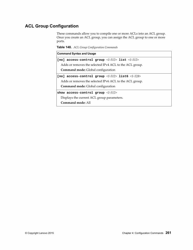
© Copyright Lenovo 2015 Chapter 4: Configuration Commands 261
ACL Group Configuration
These commands allow you to compile one or more ACLs into an ACL group. Once you create an ACL group, you can assign the ACL group to one or more ports.
Table 148. ACL Group Configuration Commands
Command Syntax and Usage
[no] access-control group <1-512> list <1-512>Adds or removes the selected IPv4 ACL to the ACL group.Command mode: Global configuration
[no] access-control group <1-512> list6 <1-128>Adds or removes the selected IPv6 ACL to the ACL group.Command mode: Global configuration
show access-control group <1-512>Displays the current ACL group parameters.Command mode: All
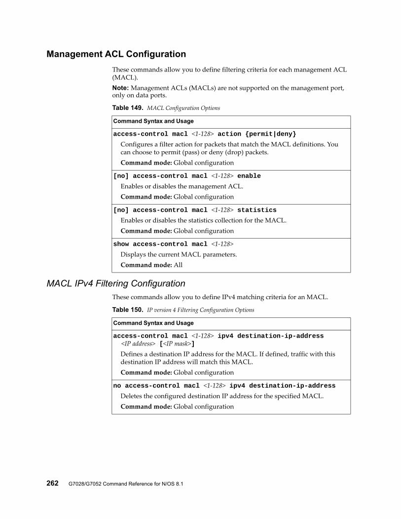
262 G7028/G7052 Command Reference for N/OS 8.1
Management ACL Configuration
These commands allow you to define filtering criteria for each management ACL (MACL).Note: Management ACLs (MACLs) are not supported on the management port, only on data ports.
MACL IPv4 Filtering ConfigurationThese commands allow you to define IPv4 matching criteria for an MACL.
Table 149. MACL Configuration Options
Command Syntax and Usage
access-control macl <1-128> action {permit|deny}Configures a filter action for packets that match the MACL definitions. You can choose to permit (pass) or deny (drop) packets.Command mode: Global configuration
[no] access-control macl <1-128> enableEnables or disables the management ACL.Command mode: Global configuration
[no] access-control macl <1-128> statisticsEnables or disables the statistics collection for the MACL.Command mode: Global configuration
show access-control macl <1-128>Displays the current MACL parameters.Command mode: All
Table 150. IP version 4 Filtering Configuration Options
Command Syntax and Usage
access-control macl <1-128> ipv4 destination-ip-address <IP address> [<IP mask>]
Defines a destination IP address for the MACL. If defined, traffic with this destination IP address will match this MACL.Command mode: Global configuration
no access-control macl <1-128> ipv4 destination-ip-addressDeletes the configured destination IP address for the specified MACL.Command mode: Global configuration
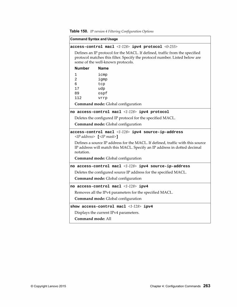
© Copyright Lenovo 2015 Chapter 4: Configuration Commands 263
access-control macl <1-128> ipv4 protocol <0-255>Defines an IP protocol for the MACL. If defined, traffic from the specified protocol matches this filter. Specify the protocol number. Listed below are some of the well-known protocols.Number Name
1 icmp2 igmp6 tcp17 udp89 ospf112 vrrp
Command mode: Global configuration
no access-control macl <1-128> ipv4 protocolDeletes the configured IP protocol for the specified MACL.Command mode: Global configuration
access-control macl <1-128> ipv4 source-ip-address <IP address> [<IP mask>]
Defines a source IP address for the MACL. If defined, traffic with this source IP address will match this MACL. Specify an IP address in dotted decimal notation.Command mode: Global configuration
no access-control macl <1-128> ipv4 source-ip-addressDeletes the configured source IP address for the specified MACL.Command mode: Global configuration
no access-control macl <1-128> ipv4Removes all the IPv4 parameters for the specified MACL.Command mode: Global configuration
show access-control macl <1-128> ipv4Displays the current IPv4 parameters.Command mode: All
Table 150. IP version 4 Filtering Configuration Options
Command Syntax and Usage
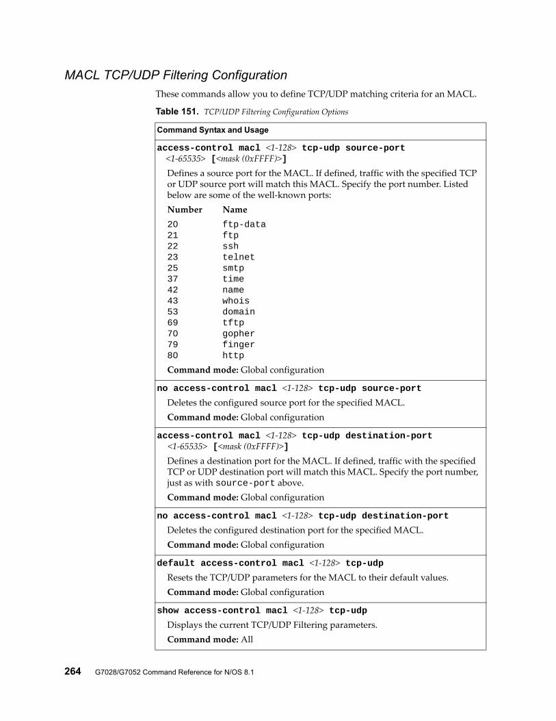
264 G7028/G7052 Command Reference for N/OS 8.1
MACL TCP/UDP Filtering ConfigurationThese commands allow you to define TCP/UDP matching criteria for an MACL.
Table 151. TCP/UDP Filtering Configuration Options
Command Syntax and Usage
access-control macl <1-128> tcp-udp source-port <1-65535> [<mask (0xFFFF)>]
Defines a source port for the MACL. If defined, traffic with the specified TCP or UDP source port will match this MACL. Specify the port number. Listed below are some of the well-known ports:Number Name20 ftp-data21 ftp22 ssh23 telnet25 smtp37 time42 name43 whois53 domain69 tftp70 gopher79 finger80 http
Command mode: Global configuration
no access-control macl <1-128> tcp-udp source-portDeletes the configured source port for the specified MACL.Command mode: Global configuration
access-control macl <1-128> tcp-udp destination-port <1-65535> [<mask (0xFFFF)>]
Defines a destination port for the MACL. If defined, traffic with the specified TCP or UDP destination port will match this MACL. Specify the port number, just as with source-port above.Command mode: Global configuration
no access-control macl <1-128> tcp-udp destination-portDeletes the configured destination port for the specified MACL.Command mode: Global configuration
default access-control macl <1-128> tcp-udpResets the TCP/UDP parameters for the MACL to their default values.Command mode: Global configuration
show access-control macl <1-128> tcp-udpDisplays the current TCP/UDP Filtering parameters.Command mode: All
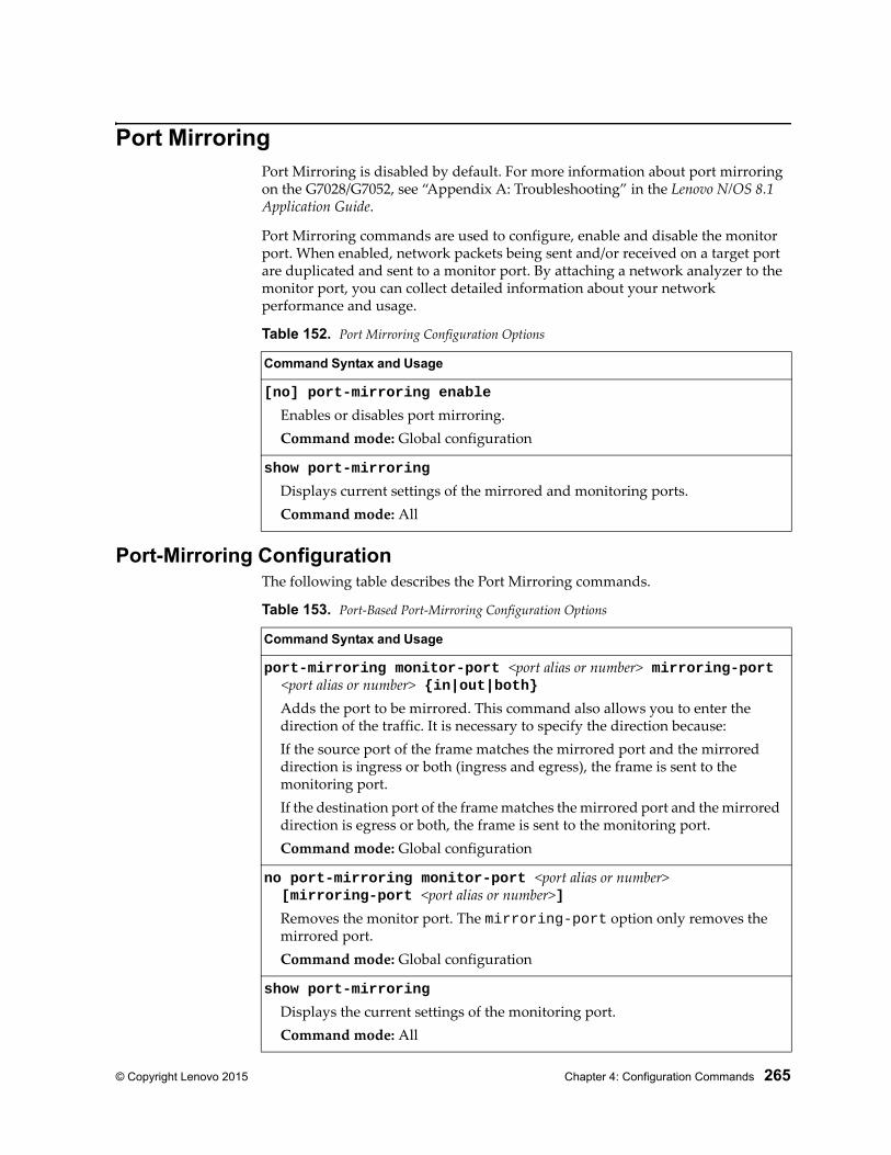
© Copyright Lenovo 2015 Chapter 4: Configuration Commands 265
Port MirroringPort Mirroring is disabled by default. For more information about port mirroring on the G7028/G7052, see “Appendix A: Troubleshooting” in the Lenovo N/OS 8.1 Application Guide.
Port Mirroring commands are used to configure, enable and disable the monitor port. When enabled, network packets being sent and/or received on a target port are duplicated and sent to a monitor port. By attaching a network analyzer to the monitor port, you can collect detailed information about your network performance and usage.
Port-Mirroring ConfigurationThe following table describes the Port Mirroring commands.
Table 152. Port Mirroring Configuration Options
Command Syntax and Usage
[no] port-mirroring enable
Enables or disables port mirroring.Command mode: Global configuration
show port-mirroring
Displays current settings of the mirrored and monitoring ports.Command mode: All
Table 153. Port-Based Port-Mirroring Configuration Options
Command Syntax and Usage
port-mirroring monitor-port <port alias or number> mirroring-port <port alias or number> {in|out|both}
Adds the port to be mirrored. This command also allows you to enter the direction of the traffic. It is necessary to specify the direction because:If the source port of the frame matches the mirrored port and the mirrored direction is ingress or both (ingress and egress), the frame is sent to the monitoring port.If the destination port of the frame matches the mirrored port and the mirrored direction is egress or both, the frame is sent to the monitoring port.Command mode: Global configuration
no port-mirroring monitor-port <port alias or number> [mirroring-port <port alias or number>]
Removes the monitor port. The mirroring-port option only removes the mirrored port.Command mode: Global configuration
show port-mirroring
Displays the current settings of the monitoring port.Command mode: All
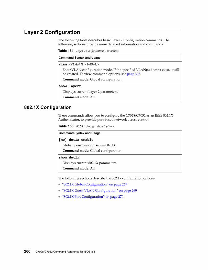
266 G7028/G7052 Command Reference for N/OS 8.1
Layer 2 ConfigurationThe following table describes basic Layer 2 Configuration commands. The following sections provide more detailed information and commands.
802.1X Configuration
These commands allow you to configure the G7028/G7052 as an IEEE 802.1X Authenticator, to provide port-based network access control.
The following sections describe the 802.1x configuration options:
“802.1X Global Configuration” on page 267
“802.1X Guest VLAN Configuration” on page 269
“802.1X Port Configuration” on page 270
Table 154. Layer 2 Configuration Commands
Command Syntax and Usage
vlan <VLAN ID (1-4094)>Enter VLAN configuration mode. If the specified VLAN(s) doesn’t exist, it will be created. To view command options, see page 307.Command mode: Global configuration
show layer2
Displays current Layer 2 parameters.Command mode: All
Table 155. 802.1x Configuration Options
Command Syntax and Usage
[no] dot1x enable
Globally enables or disables 802.1X.Command mode: Global configuration
show dot1x
Displays current 802.1X parameters.Command mode: All
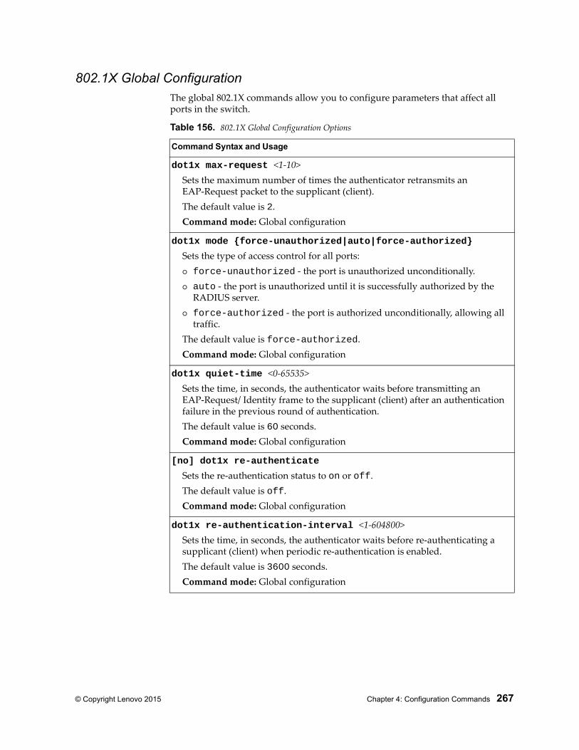
© Copyright Lenovo 2015 Chapter 4: Configuration Commands 267
802.1X Global ConfigurationThe global 802.1X commands allow you to configure parameters that affect all ports in the switch.
Table 156. 802.1X Global Configuration Options
Command Syntax and Usage
dot1x max-request <1-10>Sets the maximum number of times the authenticator retransmits an EAP-Request packet to the supplicant (client).The default value is 2.Command mode: Global configuration
dot1x mode {force-unauthorized|auto|force-authorized}
Sets the type of access control for all ports: force-unauthorized - the port is unauthorized unconditionally. auto - the port is unauthorized until it is successfully authorized by the
RADIUS server. force-authorized - the port is authorized unconditionally, allowing all
traffic.The default value is force-authorized.Command mode: Global configuration
dot1x quiet-time <0-65535>Sets the time, in seconds, the authenticator waits before transmitting an EAP-Request/ Identity frame to the supplicant (client) after an authentication failure in the previous round of authentication.The default value is 60 seconds.Command mode: Global configuration
[no] dot1x re-authenticate
Sets the re-authentication status to on or off.The default value is off.Command mode: Global configuration
dot1x re-authentication-interval <1-604800>Sets the time, in seconds, the authenticator waits before re-authenticating a supplicant (client) when periodic re-authentication is enabled.The default value is 3600 seconds.Command mode: Global configuration
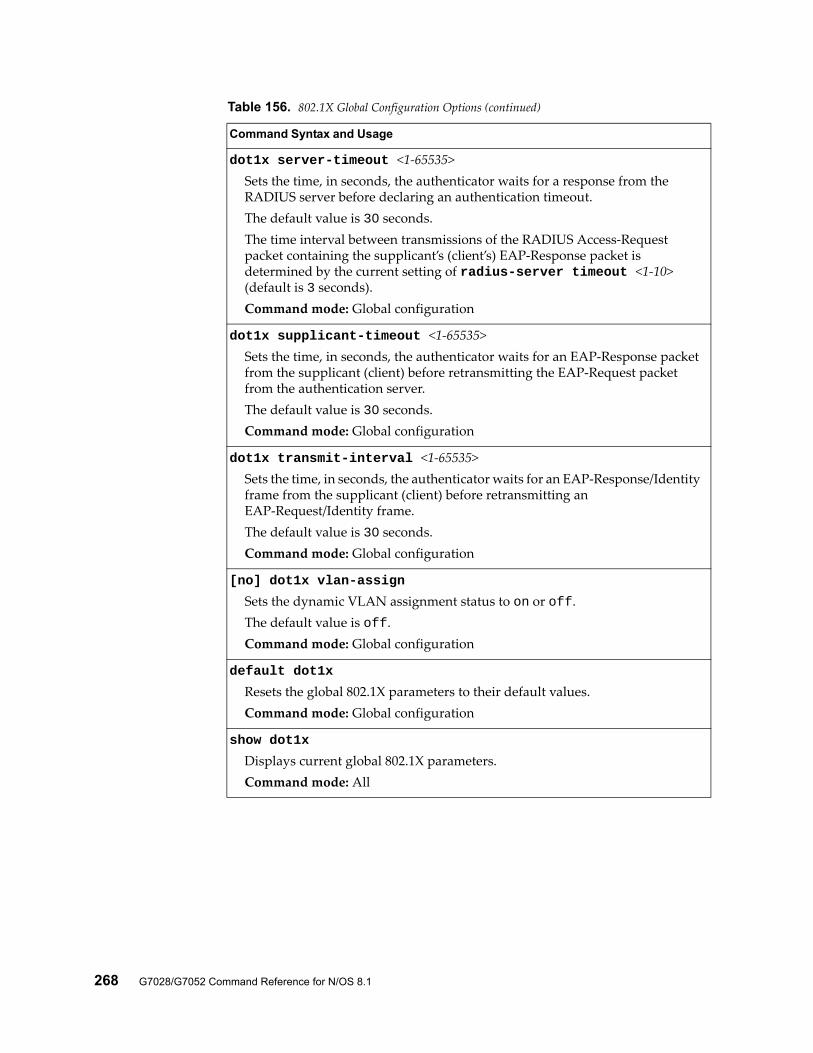
268 G7028/G7052 Command Reference for N/OS 8.1
dot1x server-timeout <1-65535>Sets the time, in seconds, the authenticator waits for a response from the RADIUS server before declaring an authentication timeout.The default value is 30 seconds.The time interval between transmissions of the RADIUS Access-Request packet containing the supplicant’s (client’s) EAP-Response packet is determined by the current setting of radius-server timeout <1-10> (default is 3 seconds).Command mode: Global configuration
dot1x supplicant-timeout <1-65535>Sets the time, in seconds, the authenticator waits for an EAP-Response packet from the supplicant (client) before retransmitting the EAP-Request packet from the authentication server.The default value is 30 seconds.Command mode: Global configuration
dot1x transmit-interval <1-65535>Sets the time, in seconds, the authenticator waits for an EAP-Response/Identity frame from the supplicant (client) before retransmitting an EAP-Request/Identity frame.The default value is 30 seconds.Command mode: Global configuration
[no] dot1x vlan-assign
Sets the dynamic VLAN assignment status to on or off.The default value is off.Command mode: Global configuration
default dot1x
Resets the global 802.1X parameters to their default values.Command mode: Global configuration
show dot1x
Displays current global 802.1X parameters.Command mode: All
Table 156. 802.1X Global Configuration Options (continued)
Command Syntax and Usage
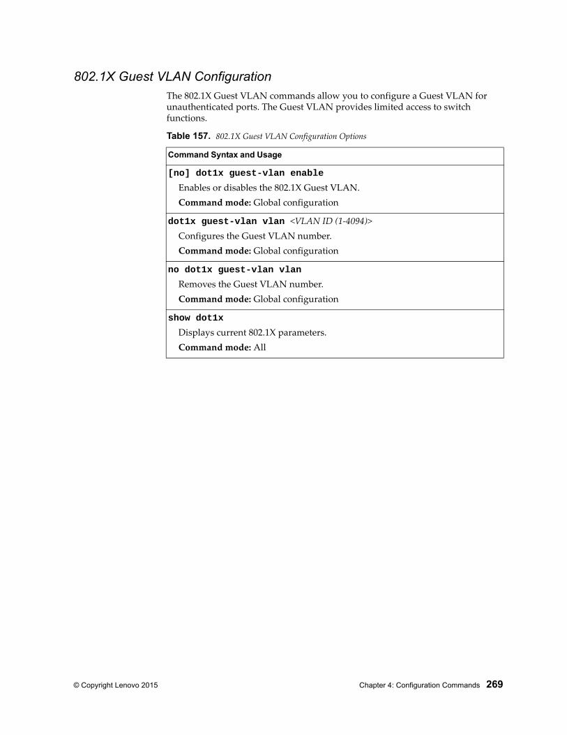
© Copyright Lenovo 2015 Chapter 4: Configuration Commands 269
802.1X Guest VLAN ConfigurationThe 802.1X Guest VLAN commands allow you to configure a Guest VLAN for unauthenticated ports. The Guest VLAN provides limited access to switch functions.
Table 157. 802.1X Guest VLAN Configuration Options
Command Syntax and Usage
[no] dot1x guest-vlan enable
Enables or disables the 802.1X Guest VLAN.Command mode: Global configuration
dot1x guest-vlan vlan <VLAN ID (1-4094)>Configures the Guest VLAN number.Command mode: Global configuration
no dot1x guest-vlan vlan
Removes the Guest VLAN number.Command mode: Global configuration
show dot1x
Displays current 802.1X parameters.Command mode: All
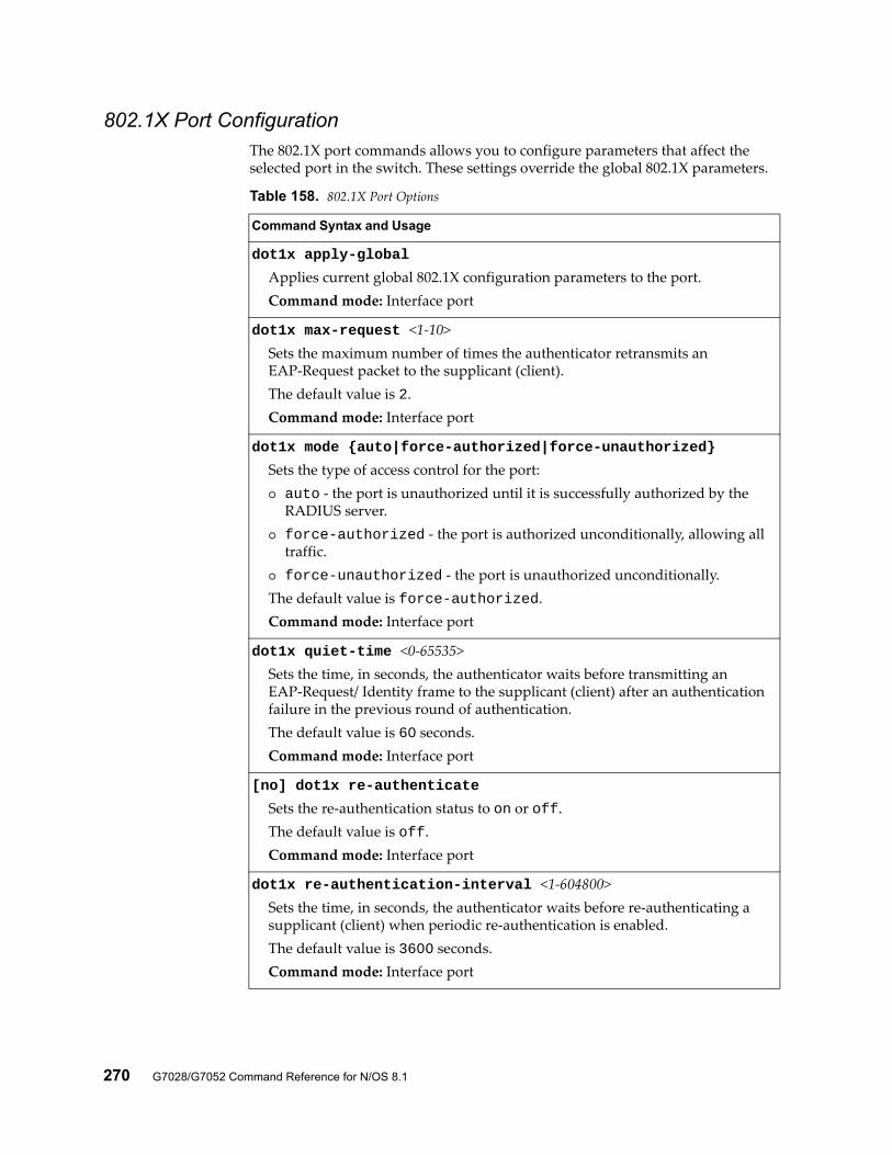
270 G7028/G7052 Command Reference for N/OS 8.1
802.1X Port ConfigurationThe 802.1X port commands allows you to configure parameters that affect the selected port in the switch. These settings override the global 802.1X parameters.
Table 158. 802.1X Port Options
Command Syntax and Usage
dot1x apply-global
Applies current global 802.1X configuration parameters to the port.Command mode: Interface port
dot1x max-request <1-10>Sets the maximum number of times the authenticator retransmits an EAP-Request packet to the supplicant (client).The default value is 2.Command mode: Interface port
dot1x mode {auto|force-authorized|force-unauthorized}
Sets the type of access control for the port: auto - the port is unauthorized until it is successfully authorized by the
RADIUS server. force-authorized - the port is authorized unconditionally, allowing all
traffic. force-unauthorized - the port is unauthorized unconditionally.The default value is force-authorized.Command mode: Interface port
dot1x quiet-time <0-65535>Sets the time, in seconds, the authenticator waits before transmitting an EAP-Request/ Identity frame to the supplicant (client) after an authentication failure in the previous round of authentication.The default value is 60 seconds.Command mode: Interface port
[no] dot1x re-authenticate
Sets the re-authentication status to on or off.The default value is off.Command mode: Interface port
dot1x re-authentication-interval <1-604800>Sets the time, in seconds, the authenticator waits before re-authenticating a supplicant (client) when periodic re-authentication is enabled.The default value is 3600 seconds.Command mode: Interface port
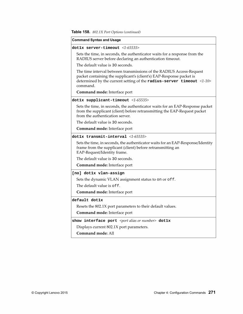
© Copyright Lenovo 2015 Chapter 4: Configuration Commands 271
dot1x server-timeout <1-65535>Sets the time, in seconds, the authenticator waits for a response from the RADIUS server before declaring an authentication timeout.The default value is 30 seconds.The time interval between transmissions of the RADIUS Access-Request packet containing the supplicant’s (client’s) EAP-Response packet is determined by the current setting of the radius-server timeout <1-10> command.Command mode: Interface port
dot1x supplicant-timeout <1-65535>Sets the time, in seconds, the authenticator waits for an EAP-Response packet from the supplicant (client) before retransmitting the EAP-Request packet from the authentication server.The default value is 30 seconds.Command mode: Interface port
dot1x transmit-interval <1-65535>Sets the time, in seconds, the authenticator waits for an EAP-Response/Identity frame from the supplicant (client) before retransmitting an EAP-Request/Identity frame.The default value is 30 seconds.Command mode: Interface port
[no] dot1x vlan-assign
Sets the dynamic VLAN assignment status to on or off.The default value is off.Command mode: Interface port
default dot1x
Resets the 802.1X port parameters to their default values.Command mode: Interface port
show interface port <port alias or number> dot1xDisplays current 802.1X port parameters.Command mode: All
Table 158. 802.1X Port Options (continued)
Command Syntax and Usage
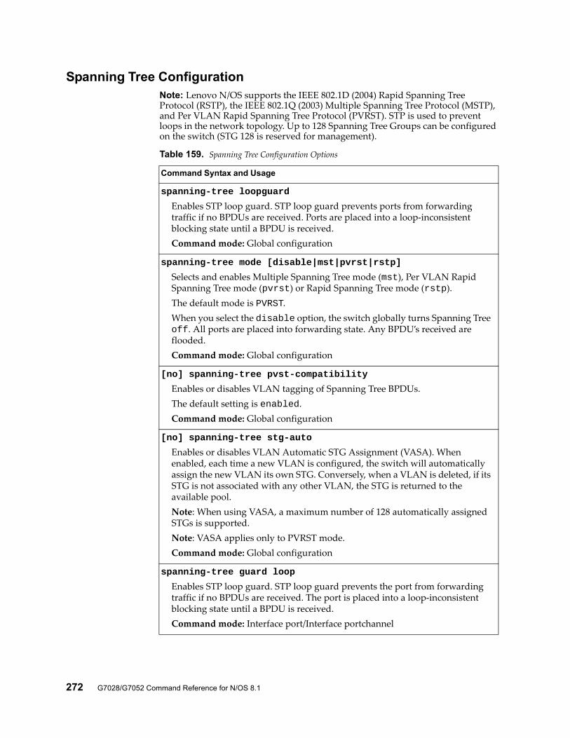
272 G7028/G7052 Command Reference for N/OS 8.1
Spanning Tree ConfigurationNote: Lenovo N/OS supports the IEEE 802.1D (2004) Rapid Spanning Tree Protocol (RSTP), the IEEE 802.1Q (2003) Multiple Spanning Tree Protocol (MSTP), and Per VLAN Rapid Spanning Tree Protocol (PVRST). STP is used to prevent loops in the network topology. Up to 128 Spanning Tree Groups can be configured on the switch (STG 128 is reserved for management).
Table 159. Spanning Tree Configuration Options
Command Syntax and Usage
spanning-tree loopguard
Enables STP loop guard. STP loop guard prevents ports from forwarding traffic if no BPDUs are received. Ports are placed into a loop-inconsistent blocking state until a BPDU is received.Command mode: Global configuration
spanning-tree mode [disable|mst|pvrst|rstp]
Selects and enables Multiple Spanning Tree mode (mst), Per VLAN Rapid Spanning Tree mode (pvrst) or Rapid Spanning Tree mode (rstp).The default mode is PVRST.When you select the disable option, the switch globally turns Spanning Tree off. All ports are placed into forwarding state. Any BPDU’s received are flooded.Command mode: Global configuration
[no] spanning-tree pvst-compatibility
Enables or disables VLAN tagging of Spanning Tree BPDUs.The default setting is enabled.Command mode: Global configuration
[no] spanning-tree stg-auto
Enables or disables VLAN Automatic STG Assignment (VASA). When enabled, each time a new VLAN is configured, the switch will automatically assign the new VLAN its own STG. Conversely, when a VLAN is deleted, if its STG is not associated with any other VLAN, the STG is returned to the available pool.Note: When using VASA, a maximum number of 128 automatically assigned STGs is supported.Note: VASA applies only to PVRST mode.Command mode: Global configuration
spanning-tree guard loop
Enables STP loop guard. STP loop guard prevents the port from forwarding traffic if no BPDUs are received. The port is placed into a loop-inconsistent blocking state until a BPDU is received.Command mode: Interface port/Interface portchannel
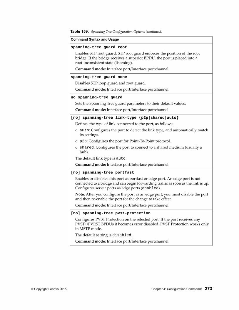
© Copyright Lenovo 2015 Chapter 4: Configuration Commands 273
spanning-tree guard root
Enables STP root guard. STP root guard enforces the position of the root bridge. If the bridge receives a superior BPDU, the port is placed into a root-inconsistent state (listening).Command mode: Interface port/Interface portchannel
spanning-tree guard none
Disables STP loop guard and root guard.Command mode: Interface port/Interface portchannel
no spanning-tree guard
Sets the Spanning Tree guard parameters to their default values.Command mode: Interface port/Interface portchannel
[no] spanning-tree link-type {p2p|shared|auto}
Defines the type of link connected to the port, as follows: auto: Configures the port to detect the link type, and automatically match
its settings. p2p: Configures the port for Point-To-Point protocol. shared: Configures the port to connect to a shared medium (usually a
hub).The default link type is auto.Command mode: Interface port/Interface portchannel
[no] spanning-tree portfast
Enables or disables this port as portfast or edge port. An edge port is not connected to a bridge and can begin forwarding traffic as soon as the link is up. Configures server ports as edge ports (enabled).Note: After you configure the port as an edge port, you must disable the port and then re-enable the port for the change to take effect.Command mode: Interface port/Interface portchannel
[no] spanning-tree pvst-protection
Configures PVST Protection on the selected port. If the port receives any PVST+/PVRST BPDUs it becomes error disabled. PVST Protection works only in MSTP mode.The default setting is disabled.Command mode: Interface port/Interface portchannel
Table 159. Spanning Tree Configuration Options (continued)
Command Syntax and Usage
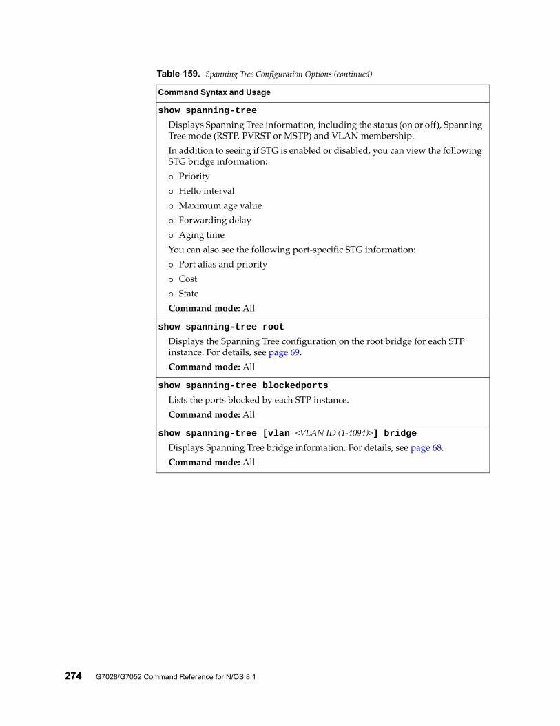
274 G7028/G7052 Command Reference for N/OS 8.1
show spanning-tree
Displays Spanning Tree information, including the status (on or off), Spanning Tree mode (RSTP, PVRST or MSTP) and VLAN membership.In addition to seeing if STG is enabled or disabled, you can view the following STG bridge information: Priority Hello interval Maximum age value Forwarding delay Aging timeYou can also see the following port-specific STG information: Port alias and priority Cost StateCommand mode: All
show spanning-tree root
Displays the Spanning Tree configuration on the root bridge for each STP instance. For details, see page 69.Command mode: All
show spanning-tree blockedports
Lists the ports blocked by each STP instance.Command mode: All
show spanning-tree [vlan <VLAN ID (1-4094)>] bridgeDisplays Spanning Tree bridge information. For details, see page 68.Command mode: All
Table 159. Spanning Tree Configuration Options (continued)
Command Syntax and Usage
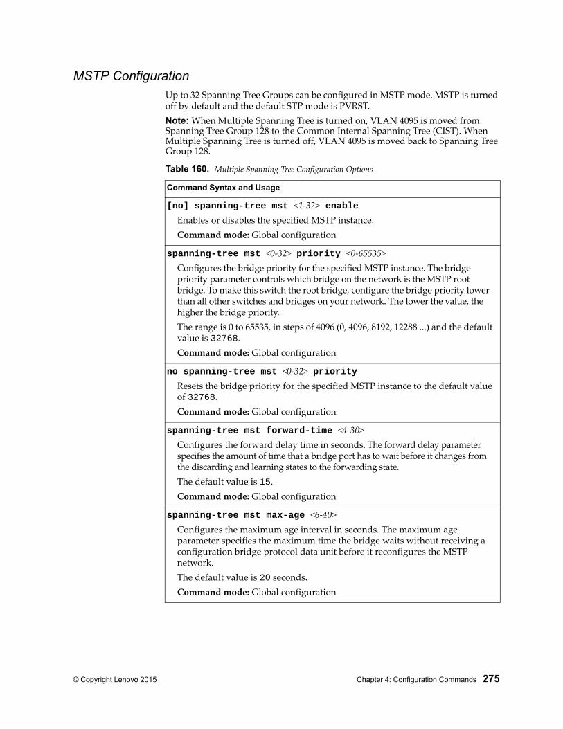
© Copyright Lenovo 2015 Chapter 4: Configuration Commands 275
MSTP ConfigurationUp to 32 Spanning Tree Groups can be configured in MSTP mode. MSTP is turned off by default and the default STP mode is PVRST.Note: When Multiple Spanning Tree is turned on, VLAN 4095 is moved from Spanning Tree Group 128 to the Common Internal Spanning Tree (CIST). When Multiple Spanning Tree is turned off, VLAN 4095 is moved back to Spanning Tree Group 128.
Table 160. Multiple Spanning Tree Configuration Options
Command Syntax and Usage
[no] spanning-tree mst <1-32> enableEnables or disables the specified MSTP instance.Command mode: Global configuration
spanning-tree mst <0-32> priority <0-65535>Configures the bridge priority for the specified MSTP instance. The bridge priority parameter controls which bridge on the network is the MSTP root bridge. To make this switch the root bridge, configure the bridge priority lower than all other switches and bridges on your network. The lower the value, the higher the bridge priority.The range is 0 to 65535, in steps of 4096 (0, 4096, 8192, 12288 ...) and the default value is 32768.Command mode: Global configuration
no spanning-tree mst <0-32> priorityResets the bridge priority for the specified MSTP instance to the default value of 32768.Command mode: Global configuration
spanning-tree mst forward-time <4-30>Configures the forward delay time in seconds. The forward delay parameter specifies the amount of time that a bridge port has to wait before it changes from the discarding and learning states to the forwarding state.The default value is 15.Command mode: Global configuration
spanning-tree mst max-age <6-40>Configures the maximum age interval in seconds. The maximum age parameter specifies the maximum time the bridge waits without receiving a configuration bridge protocol data unit before it reconfigures the MSTP network.The default value is 20 seconds.Command mode: Global configuration
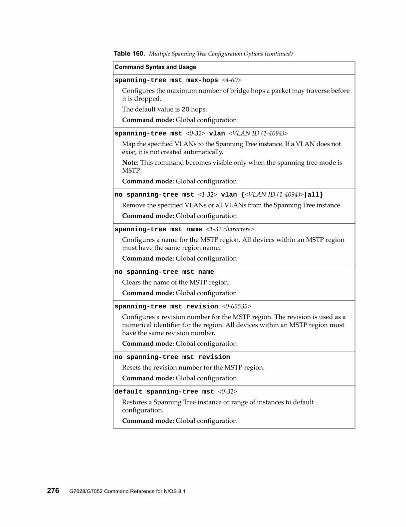
276 G7028/G7052 Command Reference for N/OS 8.1
spanning-tree mst max-hops <4-60>Configures the maximum number of bridge hops a packet may traverse before it is dropped.The default value is 20 hops.Command mode: Global configuration
spanning-tree mst <0-32> vlan <VLAN ID (1-4094)>Map the specified VLANs to the Spanning Tree instance. If a VLAN does not exist, it is not created automatically.Note: This command becomes visible only when the spanning tree mode is MSTP.Command mode: Global configuration
no spanning-tree mst <1-32> vlan {<VLAN ID (1-4094)>|all}Remove the specified VLANs or all VLANs from the Spanning Tree instance.Command mode: Global configuration
spanning-tree mst name <1-32 characters>Configures a name for the MSTP region. All devices within an MSTP region must have the same region name.Command mode: Global configuration
no spanning-tree mst name
Clears the name of the MSTP region.Command mode: Global configuration
spanning-tree mst revision <0-65535>Configures a revision number for the MSTP region. The revision is used as a numerical identifier for the region. All devices within an MSTP region must have the same revision number.Command mode: Global configuration
no spanning-tree mst revision
Resets the revision number for the MSTP region.Command mode: Global configuration
default spanning-tree mst <0-32>Restores a Spanning Tree instance or range of instances to default configuration.Command mode: Global configuration
Table 160. Multiple Spanning Tree Configuration Options (continued)
Command Syntax and Usage
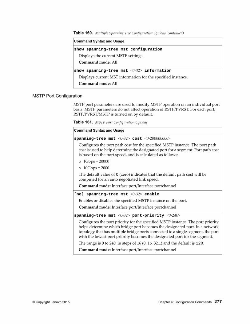
© Copyright Lenovo 2015 Chapter 4: Configuration Commands 277
MSTP Port Configuration
MSTP port parameters are used to modify MSTP operation on an individual port basis. MSTP parameters do not affect operation of RSTP/PVRST. For each port, RSTP/PVRST/MSTP is turned on by default.
show spanning-tree mst configuration
Displays the current MSTP settings.Command mode: All
show spanning-tree mst <0-32> informationDisplays current MST information for the specified instance.Command mode: All
Table 160. Multiple Spanning Tree Configuration Options (continued)
Command Syntax and Usage
Table 161. MSTP Port Configuration Options
Command Syntax and Usage
spanning-tree mst <0-32> cost <0-200000000>Configures the port path cost for the specified MSTP instance. The port path cost is used to help determine the designated port for a segment. Port path cost is based on the port speed, and is calculated as follows: 1Gbps = 20000 10Gbps = 2000The default value of 0 (zero) indicates that the default path cost will be computed for an auto negotiated link speed. Command mode: Interface port/Interface portchannel
[no] spanning-tree mst <0-32> enableEnables or disables the specified MSTP instance on the port.Command mode: Interface port/Interface portchannel
spanning-tree mst <0-32> port-priority <0-240>Configures the port priority for the specified MSTP instance. The port priority helps determine which bridge port becomes the designated port. In a network topology that has multiple bridge ports connected to a single segment, the port with the lowest port priority becomes the designated port for the segment.The range is 0 to 240, in steps of 16 (0, 16, 32...) and the default is 128.Command mode: Interface port/Interface portchannel
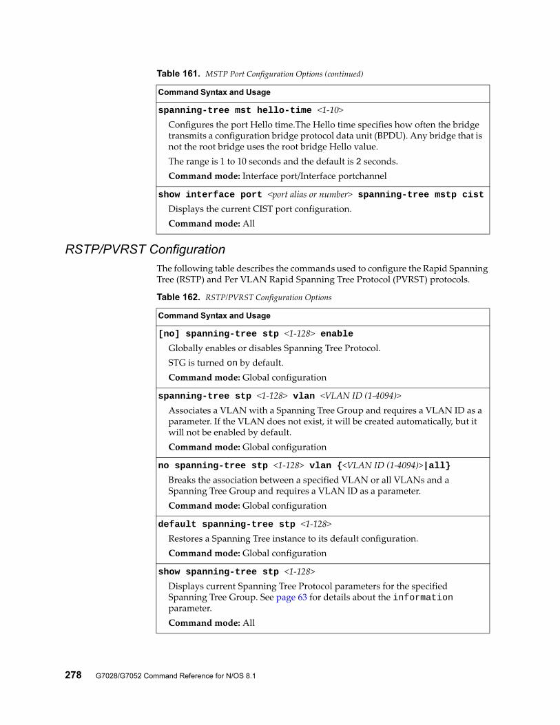
278 G7028/G7052 Command Reference for N/OS 8.1
RSTP/PVRST ConfigurationThe following table describes the commands used to configure the Rapid Spanning Tree (RSTP) and Per VLAN Rapid Spanning Tree Protocol (PVRST) protocols.
spanning-tree mst hello-time <1-10>Configures the port Hello time.The Hello time specifies how often the bridge transmits a configuration bridge protocol data unit (BPDU). Any bridge that is not the root bridge uses the root bridge Hello value.The range is 1 to 10 seconds and the default is 2 seconds.Command mode: Interface port/Interface portchannel
show interface port <port alias or number> spanning-tree mstp cistDisplays the current CIST port configuration.Command mode: All
Table 161. MSTP Port Configuration Options (continued)
Command Syntax and Usage
Table 162. RSTP/PVRST Configuration Options
Command Syntax and Usage
[no] spanning-tree stp <1-128> enableGlobally enables or disables Spanning Tree Protocol.STG is turned on by default.Command mode: Global configuration
spanning-tree stp <1-128> vlan <VLAN ID (1-4094)>Associates a VLAN with a Spanning Tree Group and requires a VLAN ID as a parameter. If the VLAN does not exist, it will be created automatically, but it will not be enabled by default.Command mode: Global configuration
no spanning-tree stp <1-128> vlan {<VLAN ID (1-4094)>|all}Breaks the association between a specified VLAN or all VLANs and a Spanning Tree Group and requires a VLAN ID as a parameter.Command mode: Global configuration
default spanning-tree stp <1-128>Restores a Spanning Tree instance to its default configuration.Command mode: Global configuration
show spanning-tree stp <1-128>Displays current Spanning Tree Protocol parameters for the specified Spanning Tree Group. See page 63 for details about the information parameter.Command mode: All
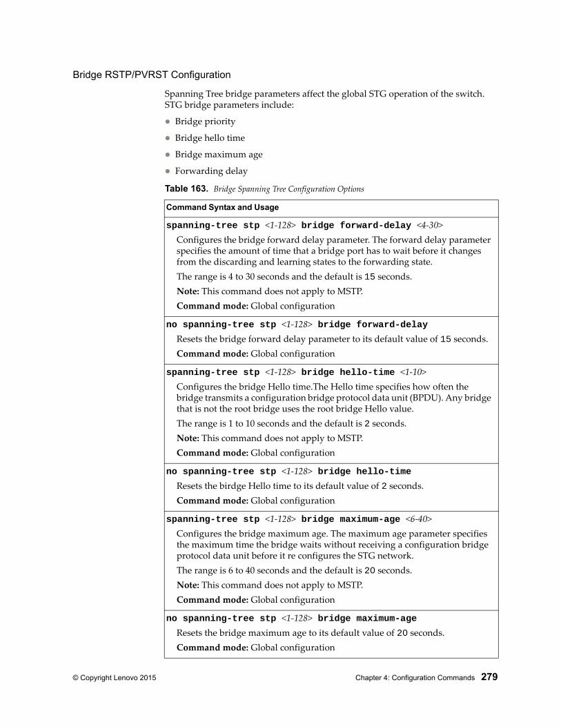
© Copyright Lenovo 2015 Chapter 4: Configuration Commands 279
Bridge RSTP/PVRST Configuration
Spanning Tree bridge parameters affect the global STG operation of the switch. STG bridge parameters include:
Bridge priority
Bridge hello time
Bridge maximum age
Forwarding delay
Table 163. Bridge Spanning Tree Configuration Options
Command Syntax and Usage
spanning-tree stp <1-128> bridge forward-delay <4-30>Configures the bridge forward delay parameter. The forward delay parameter specifies the amount of time that a bridge port has to wait before it changes from the discarding and learning states to the forwarding state.The range is 4 to 30 seconds and the default is 15 seconds.Note: This command does not apply to MSTP.Command mode: Global configuration
no spanning-tree stp <1-128> bridge forward-delayResets the bridge forward delay parameter to its default value of 15 seconds.Command mode: Global configuration
spanning-tree stp <1-128> bridge hello-time <1-10>Configures the bridge Hello time.The Hello time specifies how often the bridge transmits a configuration bridge protocol data unit (BPDU). Any bridge that is not the root bridge uses the root bridge Hello value.The range is 1 to 10 seconds and the default is 2 seconds.Note: This command does not apply to MSTP.Command mode: Global configuration
no spanning-tree stp <1-128> bridge hello-timeResets the birdge Hello time to its default value of 2 seconds.Command mode: Global configuration
spanning-tree stp <1-128> bridge maximum-age <6-40>Configures the bridge maximum age. The maximum age parameter specifies the maximum time the bridge waits without receiving a configuration bridge protocol data unit before it re configures the STG network.The range is 6 to 40 seconds and the default is 20 seconds.Note: This command does not apply to MSTP.Command mode: Global configuration
no spanning-tree stp <1-128> bridge maximum-ageResets the bridge maximum age to its default value of 20 seconds.Command mode: Global configuration
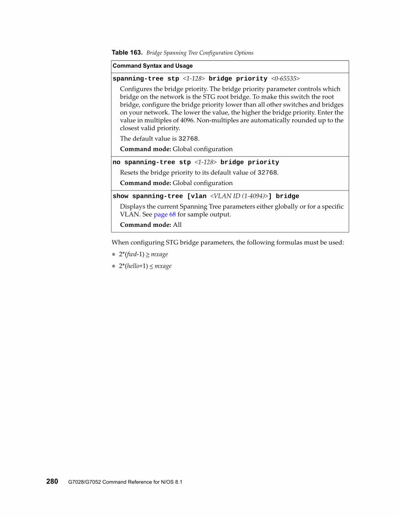
280 G7028/G7052 Command Reference for N/OS 8.1
When configuring STG bridge parameters, the following formulas must be used:
2*(fwd-1) > mxage
2*(hello+1) < mxage
spanning-tree stp <1-128> bridge priority <0-65535>Configures the bridge priority. The bridge priority parameter controls which bridge on the network is the STG root bridge. To make this switch the root bridge, configure the bridge priority lower than all other switches and bridges on your network. The lower the value, the higher the bridge priority. Enter the value in multiples of 4096. Non-multiples are automatically rounded up to the closest valid priority.The default value is 32768.Command mode: Global configuration
no spanning-tree stp <1-128> bridge priorityResets the bridge priority to its default value of 32768.Command mode: Global configuration
show spanning-tree [vlan <VLAN ID (1-4094)>] bridgeDisplays the current Spanning Tree parameters either globally or for a specific VLAN. See page 68 for sample output.Command mode: All
Table 163. Bridge Spanning Tree Configuration Options
Command Syntax and Usage
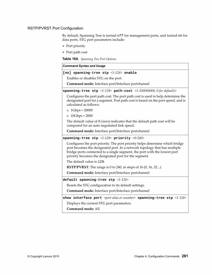
© Copyright Lenovo 2015 Chapter 4: Configuration Commands 281
RSTP/PVRST Port Configuration
By default, Spanning Tree is turned off for management ports, and turned on for data ports. STG port parameters include:
Port priority
Port path cost
Table 164. Spanning Tree Port Options
Command Syntax and Usage
[no] spanning-tree stp <1-128> enableEnables or disables STG on the port.Command mode: Interface port/Interface portchannel
spanning-tree stp <1-128> path-cost <1-200000000, 0 for default)>Configures the port path cost. The port path cost is used to help determine the designated port for a segment. Port path cost is based on the port speed, and is calculated as follows: 1Gbps = 20000 10Gbps = 2000The default value of 0 (zero) indicates that the default path cost will be computed for an auto negotiated link speed.Command mode: Interface port/Interface portchannel
spanning-tree stp <1-128> priority <0-240>Configures the port priority. The port priority helps determine which bridge port becomes the designated port. In a network topology that has multiple bridge ports connected to a single segment, the port with the lowest port priority becomes the designated port for the segment.The default value is 128.RSTP/PVRST: The range is 0 to 240, in steps of 16 (0, 16, 32...).Command mode: Interface port/Interface portchannel
default spanning-tree stp <1-128>Resets the STG configuration to its default settings.Command mode: Interface port/Interface portchannel
show interface port <port alias or number> spanning-tree stp <1-128>Displays the current STG port parameters.Command mode: All
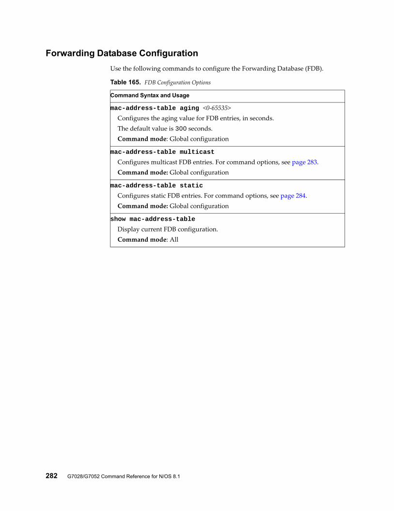
282 G7028/G7052 Command Reference for N/OS 8.1
Forwarding Database Configuration
Use the following commands to configure the Forwarding Database (FDB).
Table 165. FDB Configuration Options
Command Syntax and Usage
mac-address-table aging <0-65535>Configures the aging value for FDB entries, in seconds.The default value is 300 seconds.Command mode: Global configuration
mac-address-table multicast
Configures multicast FDB entries. For command options, see page 283.Command mode: Global configuration
mac-address-table static
Configures static FDB entries. For command options, see page 284.Command mode: Global configuration
show mac-address-table
Display current FDB configuration.Command mode: All
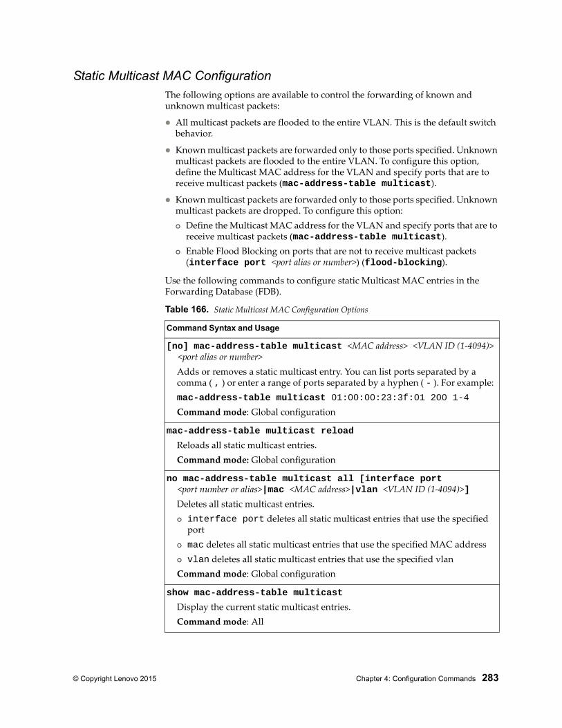
© Copyright Lenovo 2015 Chapter 4: Configuration Commands 283
Static Multicast MAC ConfigurationThe following options are available to control the forwarding of known and unknown multicast packets:
All multicast packets are flooded to the entire VLAN. This is the default switch behavior.
Known multicast packets are forwarded only to those ports specified. Unknown multicast packets are flooded to the entire VLAN. To configure this option, define the Multicast MAC address for the VLAN and specify ports that are to receive multicast packets (mac-address-table multicast).
Known multicast packets are forwarded only to those ports specified. Unknown multicast packets are dropped. To configure this option: Define the Multicast MAC address for the VLAN and specify ports that are to
receive multicast packets (mac-address-table multicast). Enable Flood Blocking on ports that are not to receive multicast packets
(interface port <port alias or number>) (flood-blocking).
Use the following commands to configure static Multicast MAC entries in the Forwarding Database (FDB).
Table 166. Static Multicast MAC Configuration Options
Command Syntax and Usage
[no] mac-address-table multicast <MAC address> <VLAN ID (1-4094)> <port alias or number>
Adds or removes a static multicast entry. You can list ports separated by a comma ( , ) or enter a range of ports separated by a hyphen ( - ). For example:mac-address-table multicast 01:00:00:23:3f:01 200 1-4
Command mode: Global configuration
mac-address-table multicast reload
Reloads all static multicast entries.Command mode: Global configuration
no mac-address-table multicast all [interface port <port number or alias>|mac <MAC address>|vlan <VLAN ID (1-4094)>]
Deletes all static multicast entries. interface port deletes all static multicast entries that use the specified
port mac deletes all static multicast entries that use the specified MAC address vlan deletes all static multicast entries that use the specified vlanCommand mode: Global configuration
show mac-address-table multicast
Display the current static multicast entries.Command mode: All
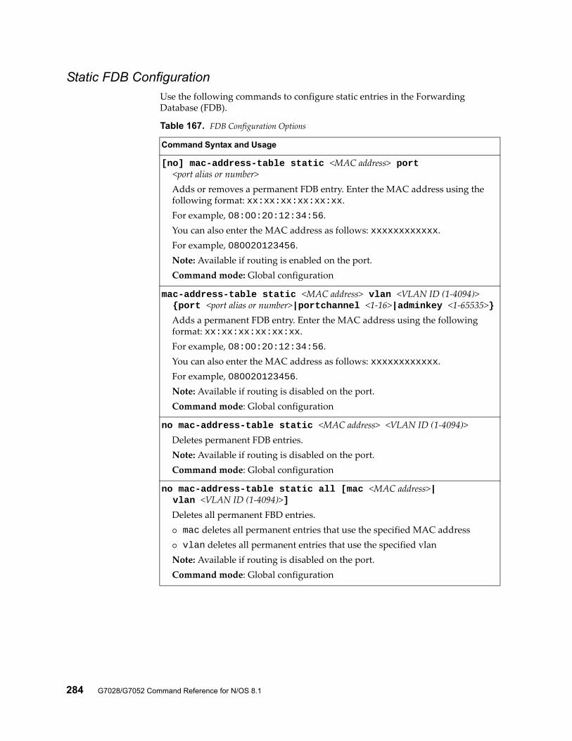
284 G7028/G7052 Command Reference for N/OS 8.1
Static FDB ConfigurationUse the following commands to configure static entries in the Forwarding Database (FDB).
Table 167. FDB Configuration Options
Command Syntax and Usage
[no] mac-address-table static <MAC address> port <port alias or number>
Adds or removes a permanent FDB entry. Enter the MAC address using the following format: xx:xx:xx:xx:xx:xx.For example, 08:00:20:12:34:56.You can also enter the MAC address as follows: xxxxxxxxxxxx.For example, 080020123456.Note: Available if routing is enabled on the port.Command mode: Global configuration
mac-address-table static <MAC address> vlan <VLAN ID (1-4094)> {port <port alias or number>|portchannel <1-16>|adminkey <1-65535>}
Adds a permanent FDB entry. Enter the MAC address using the following format: xx:xx:xx:xx:xx:xx.For example, 08:00:20:12:34:56.You can also enter the MAC address as follows: xxxxxxxxxxxx.For example, 080020123456.Note: Available if routing is disabled on the port.Command mode: Global configuration
no mac-address-table static <MAC address> <VLAN ID (1-4094)>Deletes permanent FDB entries.Note: Available if routing is disabled on the port.Command mode: Global configuration
no mac-address-table static all [mac <MAC address>| vlan <VLAN ID (1-4094)>]
Deletes all permanent FBD entries. mac deletes all permanent entries that use the specified MAC address vlan deletes all permanent entries that use the specified vlanNote: Available if routing is disabled on the port.Command mode: Global configuration
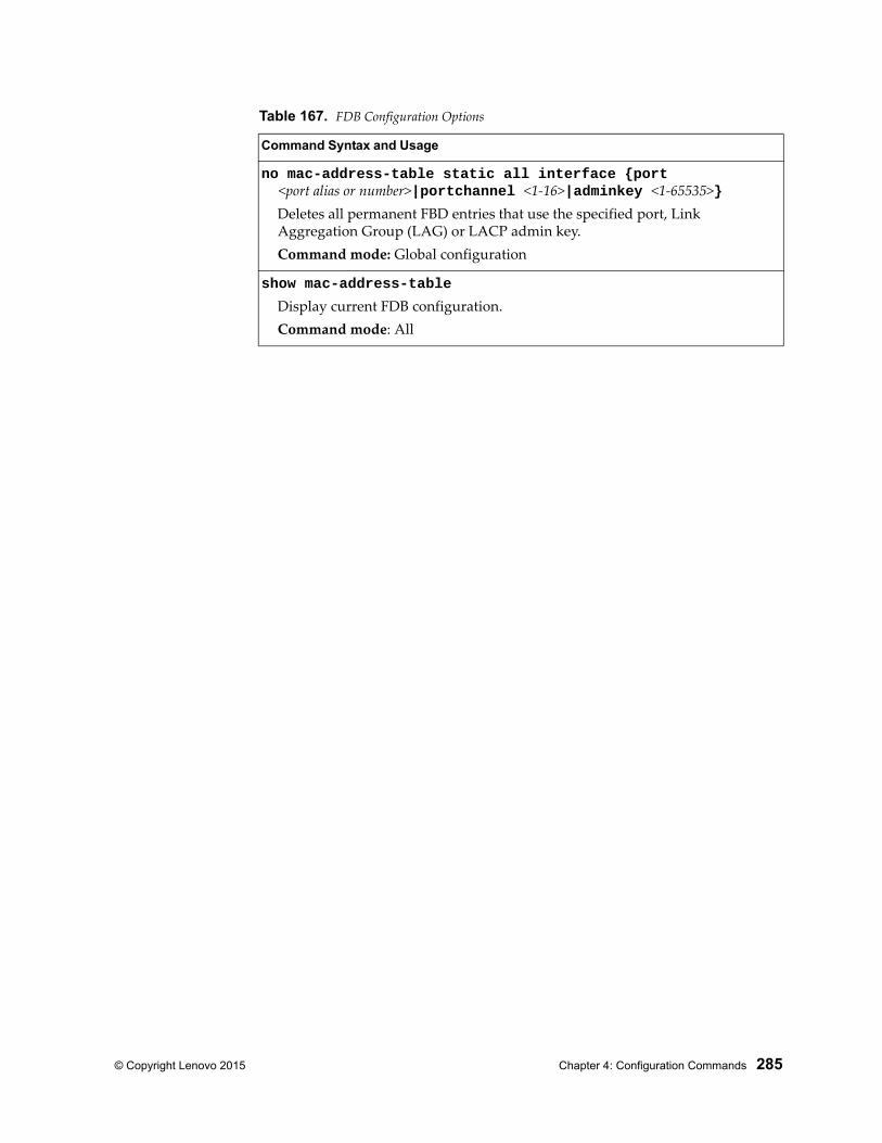
© Copyright Lenovo 2015 Chapter 4: Configuration Commands 285
no mac-address-table static all interface {port <port alias or number>|portchannel <1-16>|adminkey <1-65535>}
Deletes all permanent FBD entries that use the specified port, Link Aggregation Group (LAG) or LACP admin key.Command mode: Global configuration
show mac-address-table
Display current FDB configuration.Command mode: All
Table 167. FDB Configuration Options
Command Syntax and Usage
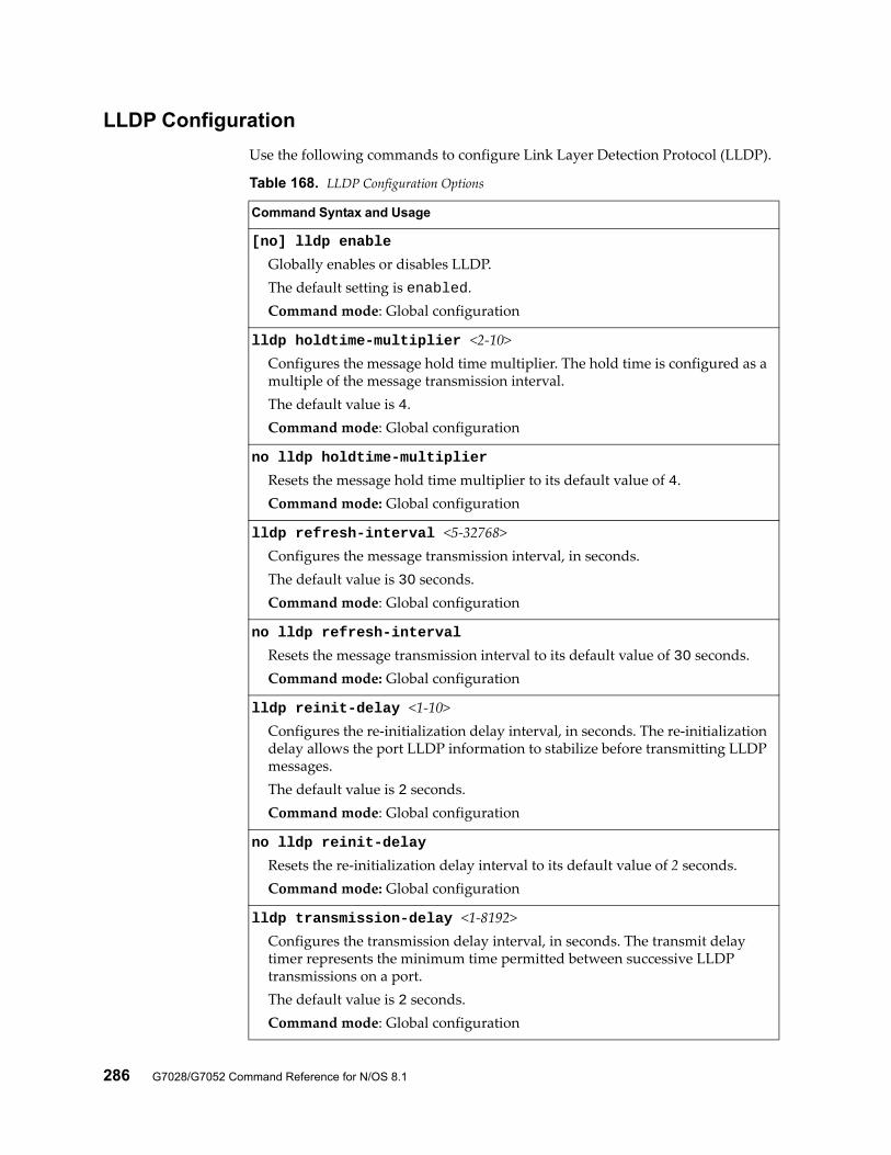
286 G7028/G7052 Command Reference for N/OS 8.1
LLDP Configuration
Use the following commands to configure Link Layer Detection Protocol (LLDP).
Table 168. LLDP Configuration Options
Command Syntax and Usage
[no] lldp enable
Globally enables or disables LLDP.The default setting is enabled.Command mode: Global configuration
lldp holdtime-multiplier <2-10>Configures the message hold time multiplier. The hold time is configured as a multiple of the message transmission interval.The default value is 4.Command mode: Global configuration
no lldp holdtime-multiplier
Resets the message hold time multiplier to its default value of 4.Command mode: Global configuration
lldp refresh-interval <5-32768>Configures the message transmission interval, in seconds.The default value is 30 seconds.Command mode: Global configuration
no lldp refresh-interval
Resets the message transmission interval to its default value of 30 seconds.Command mode: Global configuration
lldp reinit-delay <1-10>Configures the re-initialization delay interval, in seconds. The re-initialization delay allows the port LLDP information to stabilize before transmitting LLDP messages.The default value is 2 seconds.Command mode: Global configuration
no lldp reinit-delay
Resets the re-initialization delay interval to its default value of 2 seconds.Command mode: Global configuration
lldp transmission-delay <1-8192>Configures the transmission delay interval, in seconds. The transmit delay timer represents the minimum time permitted between successive LLDP transmissions on a port.The default value is 2 seconds.Command mode: Global configuration
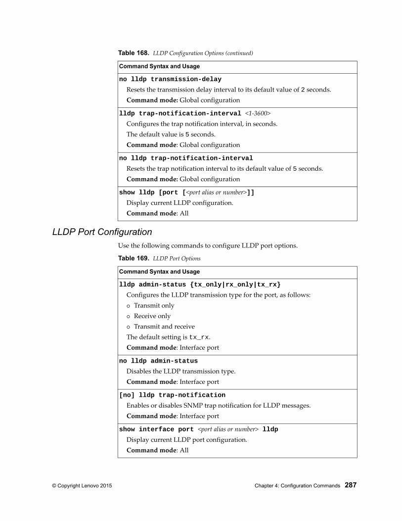
© Copyright Lenovo 2015 Chapter 4: Configuration Commands 287
LLDP Port ConfigurationUse the following commands to configure LLDP port options.
no lldp transmission-delay
Resets the transmission delay interval to its default value of 2 seconds.Command mode: Global configuration
lldp trap-notification-interval <1-3600>Configures the trap notification interval, in seconds.The default value is 5 seconds.Command mode: Global configuration
no lldp trap-notification-interval
Resets the trap notification interval to its default value of 5 seconds.Command mode: Global configuration
show lldp [port [<port alias or number>]]Display current LLDP configuration.Command mode: All
Table 168. LLDP Configuration Options (continued)
Command Syntax and Usage
Table 169. LLDP Port Options
Command Syntax and Usage
lldp admin-status {tx_only|rx_only|tx_rx}
Configures the LLDP transmission type for the port, as follows: Transmit only Receive only Transmit and receiveThe default setting is tx_rx.Command mode: Interface port
no lldp admin-status
Disables the LLDP transmission type.Command mode: Interface port
[no] lldp trap-notification
Enables or disables SNMP trap notification for LLDP messages.Command mode: Interface port
show interface port <port alias or number> lldpDisplay current LLDP port configuration.Command mode: All
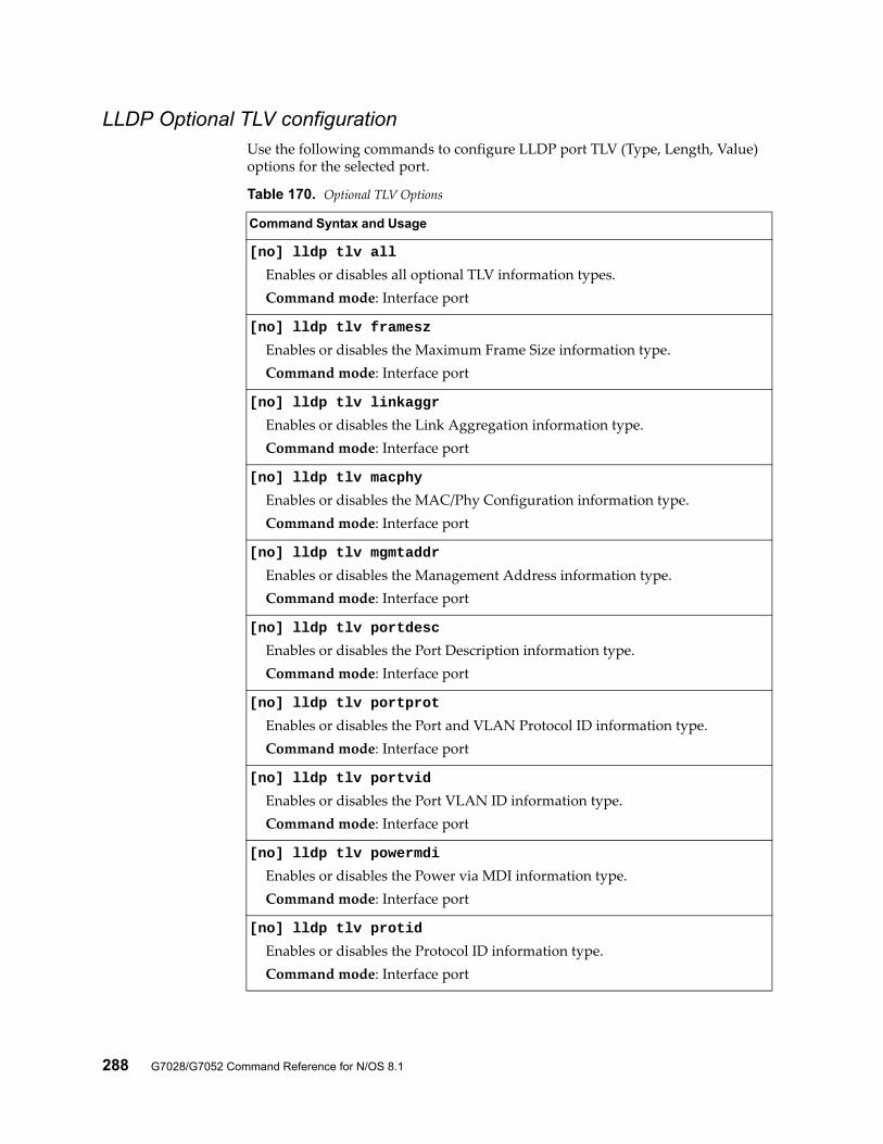
288 G7028/G7052 Command Reference for N/OS 8.1
LLDP Optional TLV configurationUse the following commands to configure LLDP port TLV (Type, Length, Value) options for the selected port.
Table 170. Optional TLV Options
Command Syntax and Usage
[no] lldp tlv all
Enables or disables all optional TLV information types.Command mode: Interface port
[no] lldp tlv framesz
Enables or disables the Maximum Frame Size information type.Command mode: Interface port
[no] lldp tlv linkaggr
Enables or disables the Link Aggregation information type.Command mode: Interface port
[no] lldp tlv macphy
Enables or disables the MAC/Phy Configuration information type.Command mode: Interface port
[no] lldp tlv mgmtaddr
Enables or disables the Management Address information type.Command mode: Interface port
[no] lldp tlv portdesc
Enables or disables the Port Description information type.Command mode: Interface port
[no] lldp tlv portprot
Enables or disables the Port and VLAN Protocol ID information type.Command mode: Interface port
[no] lldp tlv portvid
Enables or disables the Port VLAN ID information type.Command mode: Interface port
[no] lldp tlv powermdi
Enables or disables the Power via MDI information type.Command mode: Interface port
[no] lldp tlv protid
Enables or disables the Protocol ID information type.Command mode: Interface port
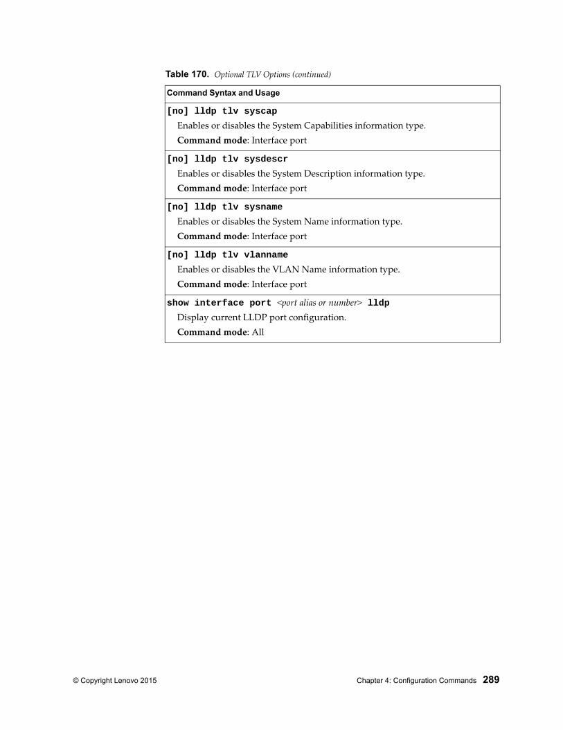
© Copyright Lenovo 2015 Chapter 4: Configuration Commands 289
[no] lldp tlv syscap
Enables or disables the System Capabilities information type.Command mode: Interface port
[no] lldp tlv sysdescr
Enables or disables the System Description information type.Command mode: Interface port
[no] lldp tlv sysname
Enables or disables the System Name information type.Command mode: Interface port
[no] lldp tlv vlanname
Enables or disables the VLAN Name information type.Command mode: Interface port
show interface port <port alias or number> lldpDisplay current LLDP port configuration.Command mode: All
Table 170. Optional TLV Options (continued)
Command Syntax and Usage
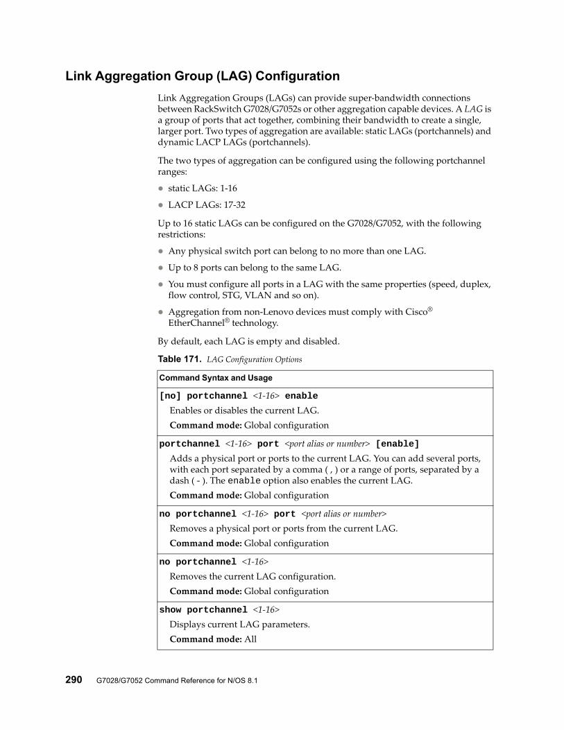
290 G7028/G7052 Command Reference for N/OS 8.1
Link Aggregation Group (LAG) Configuration
Link Aggregation Groups (LAGs) can provide super-bandwidth connections between RackSwitch G7028/G7052s or other aggregation capable devices. A LAG is a group of ports that act together, combining their bandwidth to create a single, larger port. Two types of aggregation are available: static LAGs (portchannels) and dynamic LACP LAGs (portchannels).
The two types of aggregation can be configured using the following portchannel ranges:
static LAGs: 1-16
LACP LAGs: 17-32
Up to 16 static LAGs can be configured on the G7028/G7052, with the following restrictions:
Any physical switch port can belong to no more than one LAG.
Up to 8 ports can belong to the same LAG.
You must configure all ports in a LAG with the same properties (speed, duplex, flow control, STG, VLAN and so on).
Aggregation from non-Lenovo devices must comply with Cisco® EtherChannel® technology.
By default, each LAG is empty and disabled.
Table 171. LAG Configuration Options
Command Syntax and Usage
[no] portchannel <1-16> enableEnables or disables the current LAG.Command mode: Global configuration
portchannel <1-16> port <port alias or number> [enable]Adds a physical port or ports to the current LAG. You can add several ports, with each port separated by a comma ( , ) or a range of ports, separated by a dash ( - ). The enable option also enables the current LAG.Command mode: Global configuration
no portchannel <1-16> port <port alias or number>Removes a physical port or ports from the current LAG.Command mode: Global configuration
no portchannel <1-16>Removes the current LAG configuration.Command mode: Global configuration
show portchannel <1-16>Displays current LAG parameters.Command mode: All
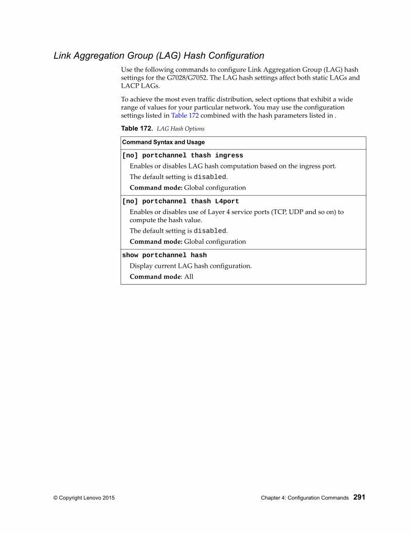
© Copyright Lenovo 2015 Chapter 4: Configuration Commands 291
Link Aggregation Group (LAG) Hash ConfigurationUse the following commands to configure Link Aggregation Group (LAG) hash settings for the G7028/G7052. The LAG hash settings affect both static LAGs and LACP LAGs.
To achieve the most even traffic distribution, select options that exhibit a wide range of values for your particular network. You may use the configuration settings listed in Table 172 combined with the hash parameters listed in .
Table 172. LAG Hash Options
Command Syntax and Usage
[no] portchannel thash ingress
Enables or disables LAG hash computation based on the ingress port.The default setting is disabled.Command mode: Global configuration
[no] portchannel thash L4port
Enables or disables use of Layer 4 service ports (TCP, UDP and so on) to compute the hash value.The default setting is disabled.Command mode: Global configuration
show portchannel hash
Display current LAG hash configuration.Command mode: All
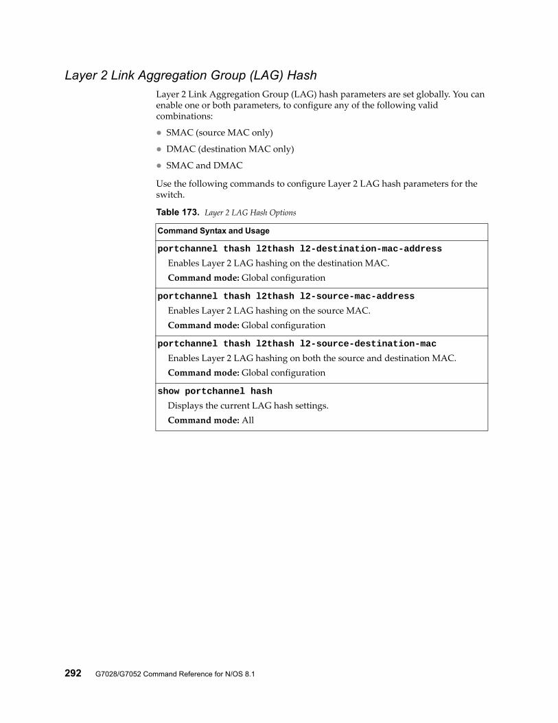
292 G7028/G7052 Command Reference for N/OS 8.1
Layer 2 Link Aggregation Group (LAG) HashLayer 2 Link Aggregation Group (LAG) hash parameters are set globally. You can enable one or both parameters, to configure any of the following valid combinations:
SMAC (source MAC only)
DMAC (destination MAC only)
SMAC and DMAC
Use the following commands to configure Layer 2 LAG hash parameters for the switch.
Table 173. Layer 2 LAG Hash Options
Command Syntax and Usage
portchannel thash l2thash l2-destination-mac-address
Enables Layer 2 LAG hashing on the destination MAC.Command mode: Global configuration
portchannel thash l2thash l2-source-mac-address
Enables Layer 2 LAG hashing on the source MAC.Command mode: Global configuration
portchannel thash l2thash l2-source-destination-mac
Enables Layer 2 LAG hashing on both the source and destination MAC.Command mode: Global configuration
show portchannel hash
Displays the current LAG hash settings.Command mode: All
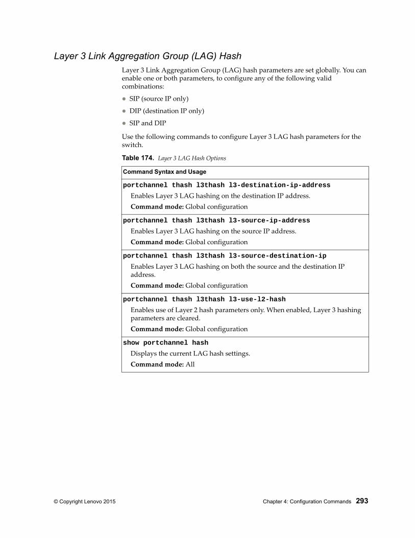
© Copyright Lenovo 2015 Chapter 4: Configuration Commands 293
Layer 3 Link Aggregation Group (LAG) HashLayer 3 Link Aggregation Group (LAG) hash parameters are set globally. You can enable one or both parameters, to configure any of the following valid combinations:
SIP (source IP only)
DIP (destination IP only)
SIP and DIP
Use the following commands to configure Layer 3 LAG hash parameters for the switch.
Table 174. Layer 3 LAG Hash Options
Command Syntax and Usage
portchannel thash l3thash l3-destination-ip-address
Enables Layer 3 LAG hashing on the destination IP address.Command mode: Global configuration
portchannel thash l3thash l3-source-ip-address
Enables Layer 3 LAG hashing on the source IP address.Command mode: Global configuration
portchannel thash l3thash l3-source-destination-ip
Enables Layer 3 LAG hashing on both the source and the destination IP address.Command mode: Global configuration
portchannel thash l3thash l3-use-l2-hash
Enables use of Layer 2 hash parameters only. When enabled, Layer 3 hashing parameters are cleared.Command mode: Global configuration
show portchannel hash
Displays the current LAG hash settings.Command mode: All
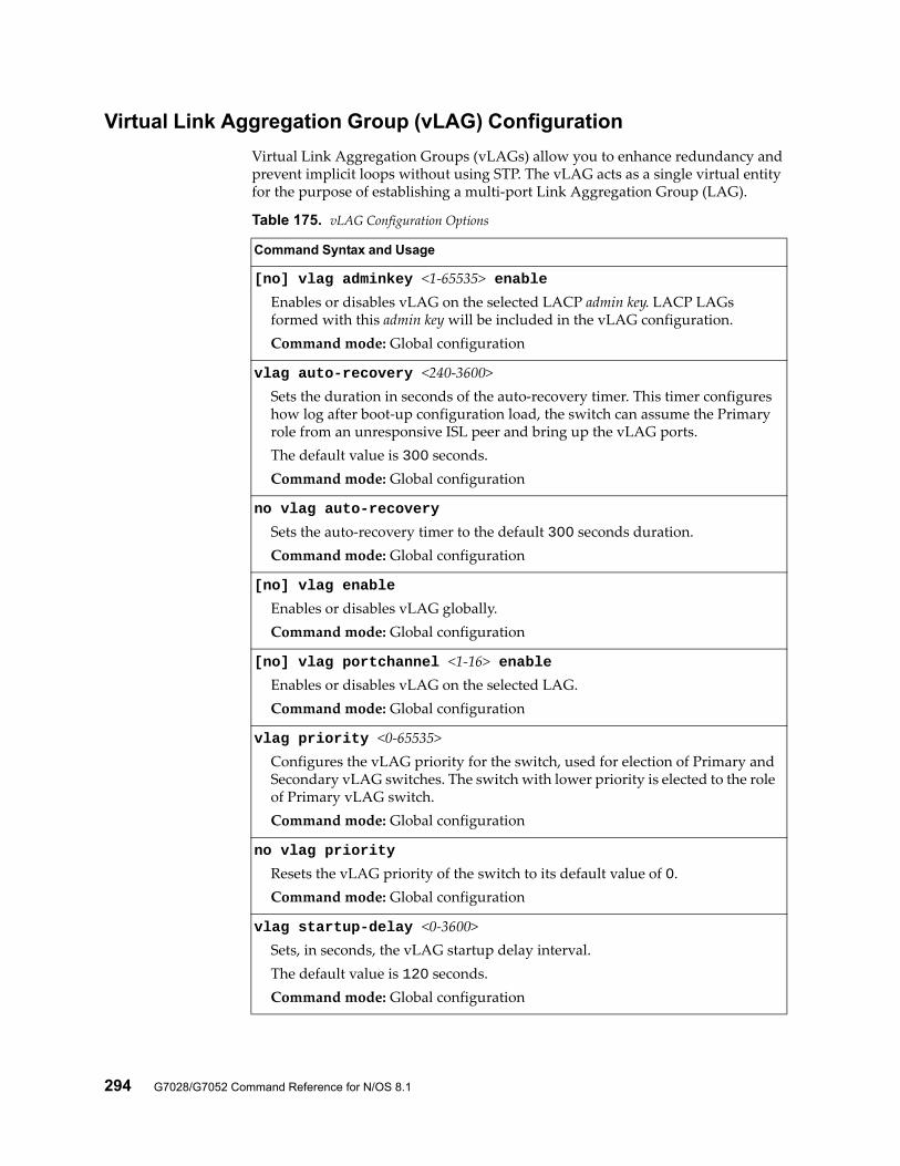
294 G7028/G7052 Command Reference for N/OS 8.1
Virtual Link Aggregation Group (vLAG) Configuration
Virtual Link Aggregation Groups (vLAGs) allow you to enhance redundancy and prevent implicit loops without using STP. The vLAG acts as a single virtual entity for the purpose of establishing a multi-port Link Aggregation Group (LAG).
Table 175. vLAG Configuration Options
Command Syntax and Usage
[no] vlag adminkey <1-65535> enableEnables or disables vLAG on the selected LACP admin key. LACP LAGs formed with this admin key will be included in the vLAG configuration.Command mode: Global configuration
vlag auto-recovery <240-3600>Sets the duration in seconds of the auto-recovery timer. This timer configures how log after boot-up configuration load, the switch can assume the Primary role from an unresponsive ISL peer and bring up the vLAG ports.The default value is 300 seconds.Command mode: Global configuration
no vlag auto-recovery
Sets the auto-recovery timer to the default 300 seconds duration.Command mode: Global configuration
[no] vlag enable
Enables or disables vLAG globally.Command mode: Global configuration
[no] vlag portchannel <1-16> enableEnables or disables vLAG on the selected LAG.Command mode: Global configuration
vlag priority <0-65535>Configures the vLAG priority for the switch, used for election of Primary and Secondary vLAG switches. The switch with lower priority is elected to the role of Primary vLAG switch.Command mode: Global configuration
no vlag priority
Resets the vLAG priority of the switch to its default value of 0.Command mode: Global configuration
vlag startup-delay <0-3600>Sets, in seconds, the vLAG startup delay interval.The default value is 120 seconds.Command mode: Global configuration
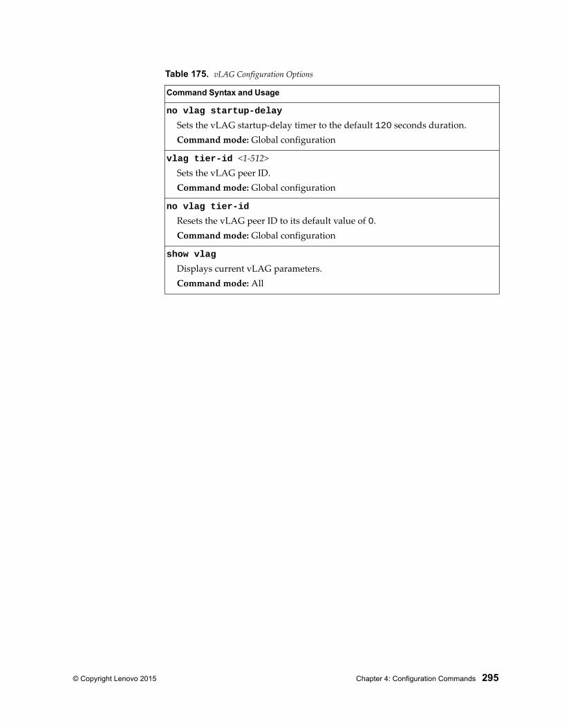
© Copyright Lenovo 2015 Chapter 4: Configuration Commands 295
no vlag startup-delay
Sets the vLAG startup-delay timer to the default 120 seconds duration.Command mode: Global configuration
vlag tier-id <1-512>Sets the vLAG peer ID.Command mode: Global configuration
no vlag tier-id
Resets the vLAG peer ID to its default value of 0.Command mode: Global configuration
show vlag
Displays current vLAG parameters.Command mode: All
Table 175. vLAG Configuration Options
Command Syntax and Usage
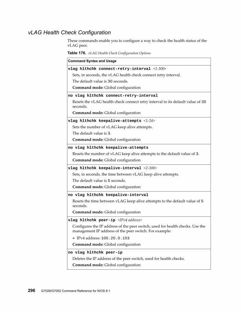
296 G7028/G7052 Command Reference for N/OS 8.1
vLAG Health Check ConfigurationThese commands enable you to configure a way to check the health status of the vLAG peer.
Table 176. vLAG Health Check Configuration Options
Command Syntax and Usage
vlag hlthchk connect-retry-interval <1-300>Sets, in seconds, the vLAG health check connect retry interval.The default value is 30 seconds.Command mode: Global configuration
no vlag hlthchk connect-retry-interval
Resets the vLAG health check connect retry interval to its default value of 30 seconds.Command mode: Global configuration
vlag hlthchk keepalive-attempts <1-24>Sets the number of vLAG keep alive attempts.The default value is 3.Command mode: Global configuration
no vlag hlthchk keepalive-attempts
Resets the number of vLAG keep alive attempts to the default value of 3.Command mode: Global configuration
vlag hlthchk keepalive-interval <2-300>Sets, in seconds, the time between vLAG keep alive attempts.The default value is 5 seconds.Command mode: Global configuration
no vlag hlthchk keepalive-interval
Resets the time between vLAG keep alive attempts to the default value of 5 seconds.Command mode: Global configuration
vlag hlthchk peer-ip <IPv4 address>Configures the IP address of the peer switch, used for health checks. Use the management IP address of the peer switch. For example:
IPv4 address: 100.20.0.103Command mode: Global configuration
no vlag hlthchk peer-ip
Deletes the IP address of the peer switch, used for health checks.Command mode: Global configuration
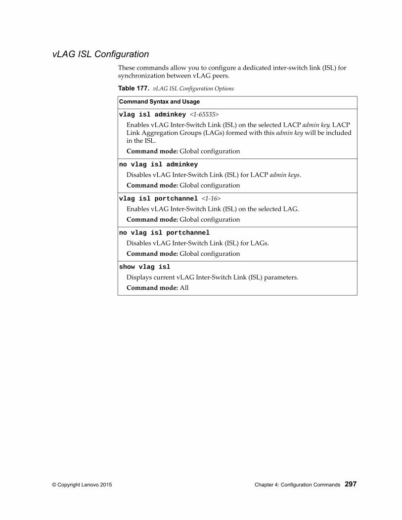
© Copyright Lenovo 2015 Chapter 4: Configuration Commands 297
vLAG ISL ConfigurationThese commands allow you to configure a dedicated inter-switch link (ISL) for synchronization between vLAG peers.
Table 177. vLAG ISL Configuration Options
Command Syntax and Usage
vlag isl adminkey <1-65535>Enables vLAG Inter-Switch Link (ISL) on the selected LACP admin key. LACP Link Aggregation Groups (LAGs) formed with this admin key will be included in the ISL.Command mode: Global configuration
no vlag isl adminkey
Disables vLAG Inter-Switch Link (ISL) for LACP admin keys.Command mode: Global configuration
vlag isl portchannel <1-16> Enables vLAG Inter-Switch Link (ISL) on the selected LAG.Command mode: Global configuration
no vlag isl portchannel
Disables vLAG Inter-Switch Link (ISL) for LAGs.Command mode: Global configuration
show vlag isl
Displays current vLAG Inter-Switch Link (ISL) parameters.Command mode: All
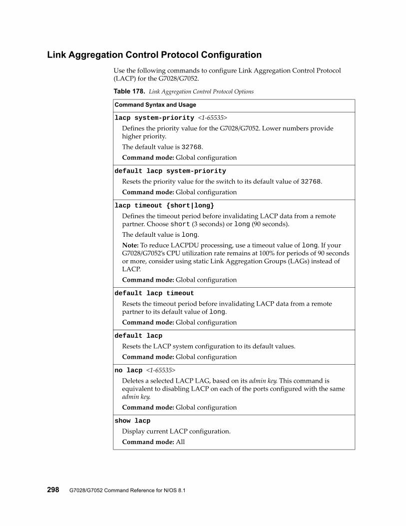
298 G7028/G7052 Command Reference for N/OS 8.1
Link Aggregation Control Protocol Configuration
Use the following commands to configure Link Aggregation Control Protocol (LACP) for the G7028/G7052.
Table 178. Link Aggregation Control Protocol Options
Command Syntax and Usage
lacp system-priority <1-65535>Defines the priority value for the G7028/G7052. Lower numbers provide higher priority.The default value is 32768.Command mode: Global configuration
default lacp system-priority
Resets the priority value for the switch to its default value of 32768.Command mode: Global configuration
lacp timeout {short|long}
Defines the timeout period before invalidating LACP data from a remote partner. Choose short (3 seconds) or long (90 seconds).The default value is long.Note: To reduce LACPDU processing, use a timeout value of long. If your G7028/G7052’s CPU utilization rate remains at 100% for periods of 90 seconds or more, consider using static Link Aggregation Groups (LAGs) instead of LACP.Command mode: Global configuration
default lacp timeout
Resets the timeout period before invalidating LACP data from a remote partner to its default value of long.Command mode: Global configuration
default lacp
Resets the LACP system configuration to its default values.Command mode: Global configuration
no lacp <1-65535>Deletes a selected LACP LAG, based on its admin key. This command is equivalent to disabling LACP on each of the ports configured with the same admin key.Command mode: Global configuration
show lacp
Display current LACP configuration.Command mode: All
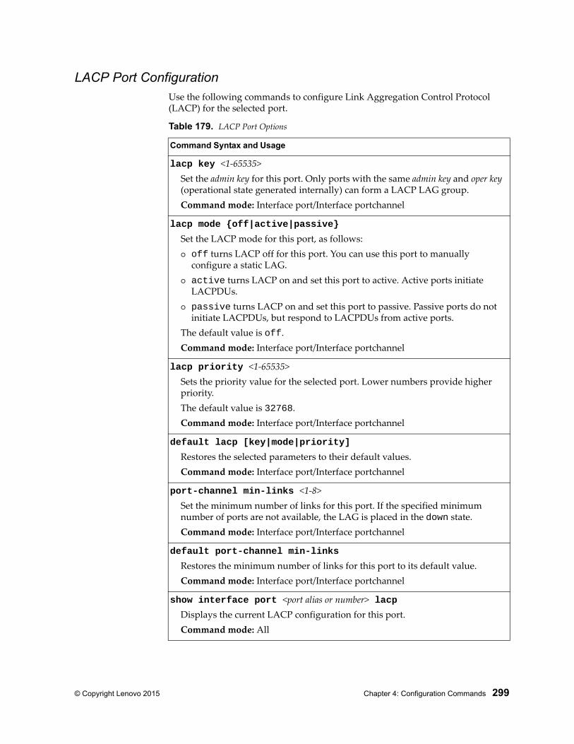
© Copyright Lenovo 2015 Chapter 4: Configuration Commands 299
LACP Port ConfigurationUse the following commands to configure Link Aggregation Control Protocol (LACP) for the selected port.
Table 179. LACP Port Options
Command Syntax and Usage
lacp key <1-65535>Set the admin key for this port. Only ports with the same admin key and oper key (operational state generated internally) can form a LACP LAG group.Command mode: Interface port/Interface portchannel
lacp mode {off|active|passive}
Set the LACP mode for this port, as follows: off turns LACP off for this port. You can use this port to manually
configure a static LAG. active turns LACP on and set this port to active. Active ports initiate
LACPDUs. passive turns LACP on and set this port to passive. Passive ports do not
initiate LACPDUs, but respond to LACPDUs from active ports.The default value is off.Command mode: Interface port/Interface portchannel
lacp priority <1-65535>Sets the priority value for the selected port. Lower numbers provide higher priority.The default value is 32768.Command mode: Interface port/Interface portchannel
default lacp [key|mode|priority]
Restores the selected parameters to their default values.Command mode: Interface port/Interface portchannel
port-channel min-links <1-8>Set the minimum number of links for this port. If the specified minimum number of ports are not available, the LAG is placed in the down state.Command mode: Interface port/Interface portchannel
default port-channel min-links
Restores the minimum number of links for this port to its default value.Command mode: Interface port/Interface portchannel
show interface port <port alias or number> lacpDisplays the current LACP configuration for this port.Command mode: All
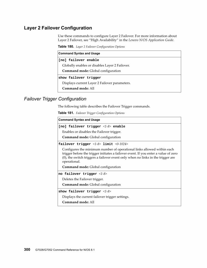
300 G7028/G7052 Command Reference for N/OS 8.1
Layer 2 Failover Configuration
Use these commands to configure Layer 2 Failover. For more information about Layer 2 Failover, see “High Availability” in the Lenovo N/OS Application Guide.
Failover Trigger Configuration
The following table describes the Failover Trigger commands.
Table 180. Layer 2 Failover Configuration Options
Command Syntax and Usage
[no] failover enable
Globally enables or disables Layer 2 Failover.Command mode: Global configuration
show failover trigger
Displays current Layer 2 Failover parameters.Command mode: All
Table 181. Failover Trigger Configuration Options
Command Syntax and Usage
[no] failover trigger <1-8> enableEnables or disables the Failover trigger.Command mode: Global configuration
failover trigger <1-8> limit <0-1024>Configures the minimum number of operational links allowed within each trigger before the trigger initiates a failover event. If you enter a value of zero (0), the switch triggers a failover event only when no links in the trigger are operational.Command mode: Global configuration
no failover trigger <1-8>Deletes the Failover trigger.Command mode: Global configuration
show failover trigger <1-8>Displays the current failover trigger settings.Command mode: All
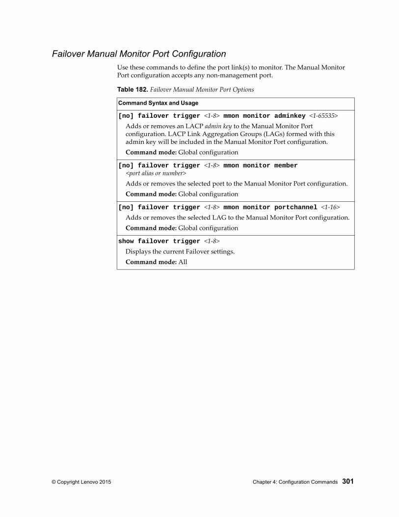
© Copyright Lenovo 2015 Chapter 4: Configuration Commands 301
Failover Manual Monitor Port ConfigurationUse these commands to define the port link(s) to monitor. The Manual Monitor Port configuration accepts any non-management port.
Table 182. Failover Manual Monitor Port Options
Command Syntax and Usage
[no] failover trigger <1-8> mmon monitor adminkey <1-65535>Adds or removes an LACP admin key to the Manual Monitor Port configuration. LACP Link Aggregation Groups (LAGs) formed with this admin key will be included in the Manual Monitor Port configuration.Command mode: Global configuration
[no] failover trigger <1-8> mmon monitor member <port alias or number>
Adds or removes the selected port to the Manual Monitor Port configuration.Command mode: Global configuration
[no] failover trigger <1-8> mmon monitor portchannel <1-16>Adds or removes the selected LAG to the Manual Monitor Port configuration.Command mode: Global configuration
show failover trigger <1-8>Displays the current Failover settings.Command mode: All
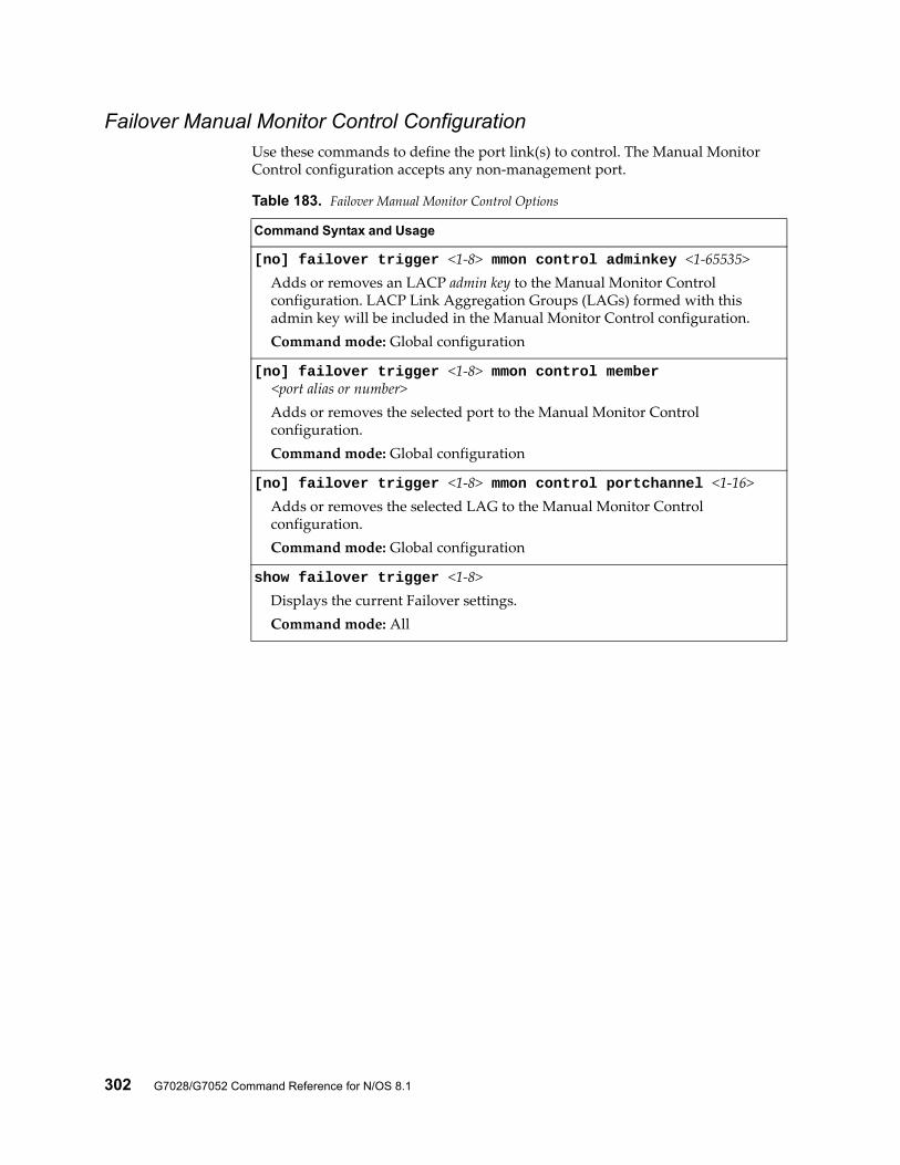
302 G7028/G7052 Command Reference for N/OS 8.1
Failover Manual Monitor Control ConfigurationUse these commands to define the port link(s) to control. The Manual Monitor Control configuration accepts any non-management port.
Table 183. Failover Manual Monitor Control Options
Command Syntax and Usage
[no] failover trigger <1-8> mmon control adminkey <1-65535>Adds or removes an LACP admin key to the Manual Monitor Control configuration. LACP Link Aggregation Groups (LAGs) formed with this admin key will be included in the Manual Monitor Control configuration.Command mode: Global configuration
[no] failover trigger <1-8> mmon control member <port alias or number>
Adds or removes the selected port to the Manual Monitor Control configuration.Command mode: Global configuration
[no] failover trigger <1-8> mmon control portchannel <1-16>Adds or removes the selected LAG to the Manual Monitor Control configuration.Command mode: Global configuration
show failover trigger <1-8>Displays the current Failover settings.Command mode: All
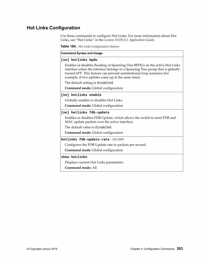
© Copyright Lenovo 2015 Chapter 4: Configuration Commands 303
Hot Links Configuration
Use these commands to configure Hot Links. For more information about Hot Links, see “Hot Links” in the Lenovo N/OS 8.1 Application Guide.
Table 184. Hot Links Configuration Options
Command Syntax and Usage
[no] hotlinks bpdu
Enables or disables flooding of Spanning-Tree BPDUs on the active Hot Links interface when the interface belongs to a Spanning Tree group that is globally turned off. This feature can prevent unintentional loop scenarios (for example, if two uplinks come up at the same time).The default setting is disabled.Command mode: Global configuration
[no] hotlinks enable
Globally enables or disables Hot Links.Command mode: Global configuration
[no] hotlinks fdb-update
Enables or disables FDB Update, which allows the switch to send FDB and MAC update packets over the active interface.The default value is disabled.Command mode: Global configuration
hotlinks fdb-update-rate <10-200>Configures the FDB Update rate in packets per second.Command mode: Global configuration
show hotlinks
Displays current Hot Links parameters.Command mode: All
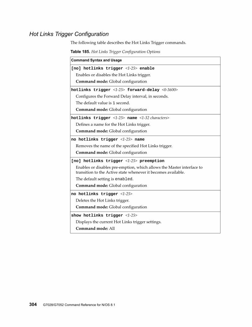
304 G7028/G7052 Command Reference for N/OS 8.1
Hot Links Trigger ConfigurationThe following table describes the Hot Links Trigger commands.
Table 185. Hot Links Trigger Configuration Options
Command Syntax and Usage
[no] hotlinks trigger <1-25> enableEnables or disables the Hot Links trigger.Command mode: Global configuration
hotlinks trigger <1-25> forward-delay <0-3600>Configures the Forward Delay interval, in seconds.The default value is 1 second.Command mode: Global configuration
hotlinks trigger <1-25> name <1-32 characters>Defines a name for the Hot Links trigger.Command mode: Global configuration
no hotlinks trigger <1-25> nameRemoves the name of the specified Hot Links trigger.Command mode: Global configuration
[no] hotlinks trigger <1-25> preemptionEnables or disables pre-emption, which allows the Master interface to transition to the Active state whenever it becomes available.The default setting is enabled.Command mode: Global configuration
no hotlinks trigger <1-25>Deletes the Hot Links trigger.Command mode: Global configuration
show hotlinks trigger <1-25>Displays the current Hot Links trigger settings.Command mode: All
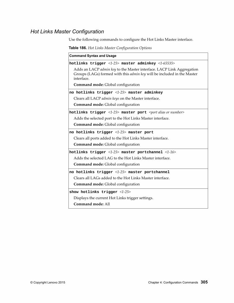
© Copyright Lenovo 2015 Chapter 4: Configuration Commands 305
Hot Links Master ConfigurationUse the following commands to configure the Hot Links Master interface.
Table 186. Hot Links Master Configuration Options
Command Syntax and Usage
hotlinks trigger <1-25> master adminkey <1-65535>Adds an LACP admin key to the Master interface. LACP Link Aggregation Groups (LAGs) formed with this admin key will be included in the Master interface.Command mode: Global configuration
no hotlinks trigger <1-25> master adminkeyClears all LACP admin keys on the Master interface.Command mode: Global configuration
hotlinks trigger <1-25> master port <port alias or number>Adds the selected port to the Hot Links Master interface.Command mode: Global configuration
no hotlinks trigger <1-25> master portClears all ports added to the Hot Links Master interface.Command mode: Global configuration
hotlinks trigger <1-25> master portchannel <1-16>Adds the selected LAG to the Hot Links Master interface.Command mode: Global configuration
no hotlinks trigger <1-25> master portchannelClears all LAGs added to the Hot Links Master interface.Command mode: Global configuration
show hotlinks trigger <1-25>Displays the current Hot Links trigger settings.Command mode: All
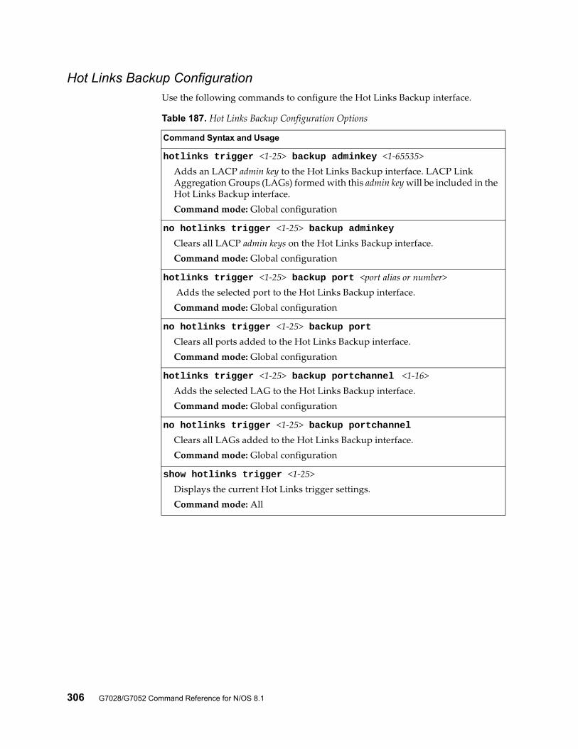
306 G7028/G7052 Command Reference for N/OS 8.1
Hot Links Backup ConfigurationUse the following commands to configure the Hot Links Backup interface.
Table 187. Hot Links Backup Configuration Options
Command Syntax and Usage
hotlinks trigger <1-25> backup adminkey <1-65535>Adds an LACP admin key to the Hot Links Backup interface. LACP Link Aggregation Groups (LAGs) formed with this admin key will be included in the Hot Links Backup interface.Command mode: Global configuration
no hotlinks trigger <1-25> backup adminkeyClears all LACP admin keys on the Hot Links Backup interface.Command mode: Global configuration
hotlinks trigger <1-25> backup port <port alias or number> Adds the selected port to the Hot Links Backup interface.Command mode: Global configuration
no hotlinks trigger <1-25> backup portClears all ports added to the Hot Links Backup interface.Command mode: Global configuration
hotlinks trigger <1-25> backup portchannel <1-16>Adds the selected LAG to the Hot Links Backup interface.Command mode: Global configuration
no hotlinks trigger <1-25> backup portchannelClears all LAGs added to the Hot Links Backup interface.Command mode: Global configuration
show hotlinks trigger <1-25>Displays the current Hot Links trigger settings.Command mode: All
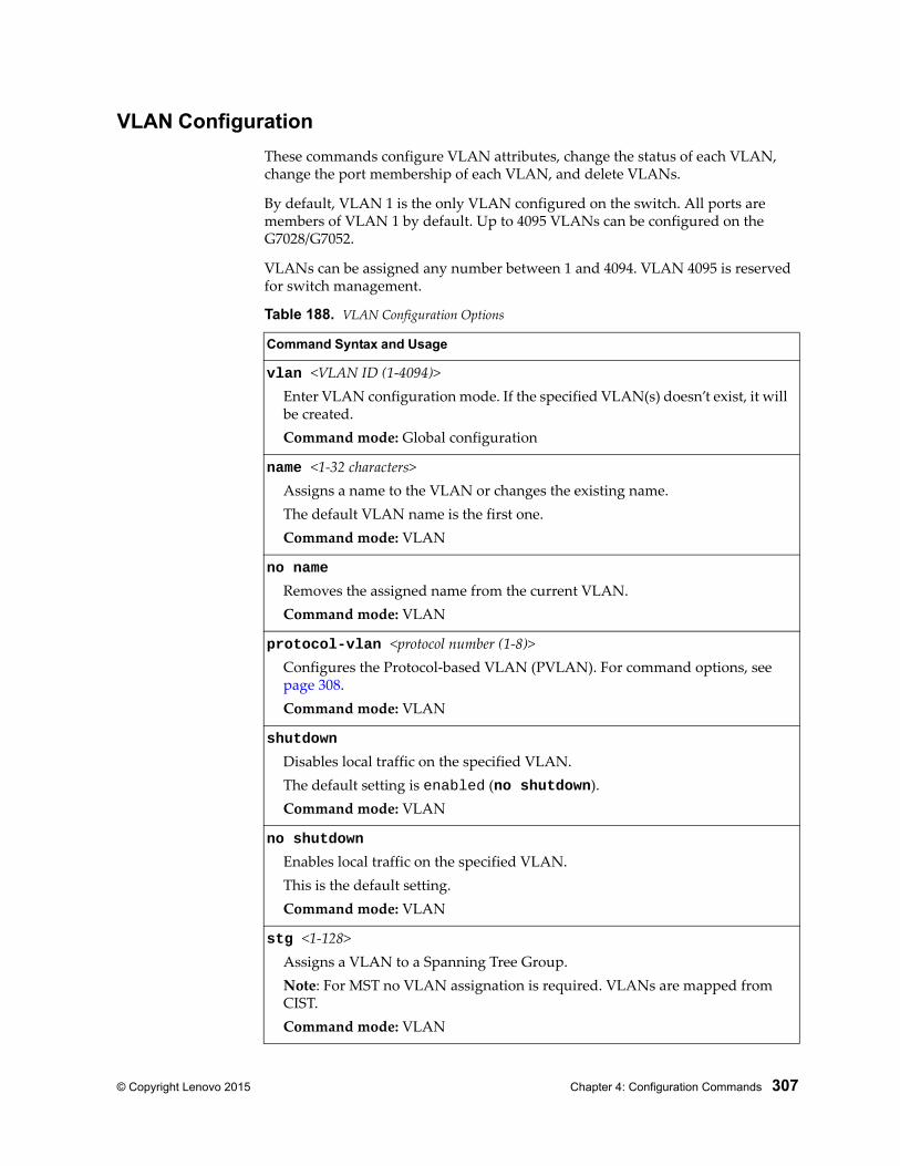
© Copyright Lenovo 2015 Chapter 4: Configuration Commands 307
VLAN Configuration
These commands configure VLAN attributes, change the status of each VLAN, change the port membership of each VLAN, and delete VLANs.
By default, VLAN 1 is the only VLAN configured on the switch. All ports are members of VLAN 1 by default. Up to 4095 VLANs can be configured on the G7028/G7052.
VLANs can be assigned any number between 1 and 4094. VLAN 4095 is reserved for switch management.
Table 188. VLAN Configuration Options
Command Syntax and Usage
vlan <VLAN ID (1-4094)>Enter VLAN configuration mode. If the specified VLAN(s) doesn’t exist, it will be created.Command mode: Global configuration
name <1-32 characters>Assigns a name to the VLAN or changes the existing name.The default VLAN name is the first one.Command mode: VLAN
no name
Removes the assigned name from the current VLAN.Command mode: VLAN
protocol-vlan <protocol number (1-8)>Configures the Protocol-based VLAN (PVLAN). For command options, see page 308.Command mode: VLAN
shutdown
Disables local traffic on the specified VLAN.The default setting is enabled (no shutdown).Command mode: VLAN
no shutdown
Enables local traffic on the specified VLAN.This is the default setting.Command mode: VLAN
stg <1-128>Assigns a VLAN to a Spanning Tree Group.Note: For MST no VLAN assignation is required. VLANs are mapped from CIST.Command mode: VLAN
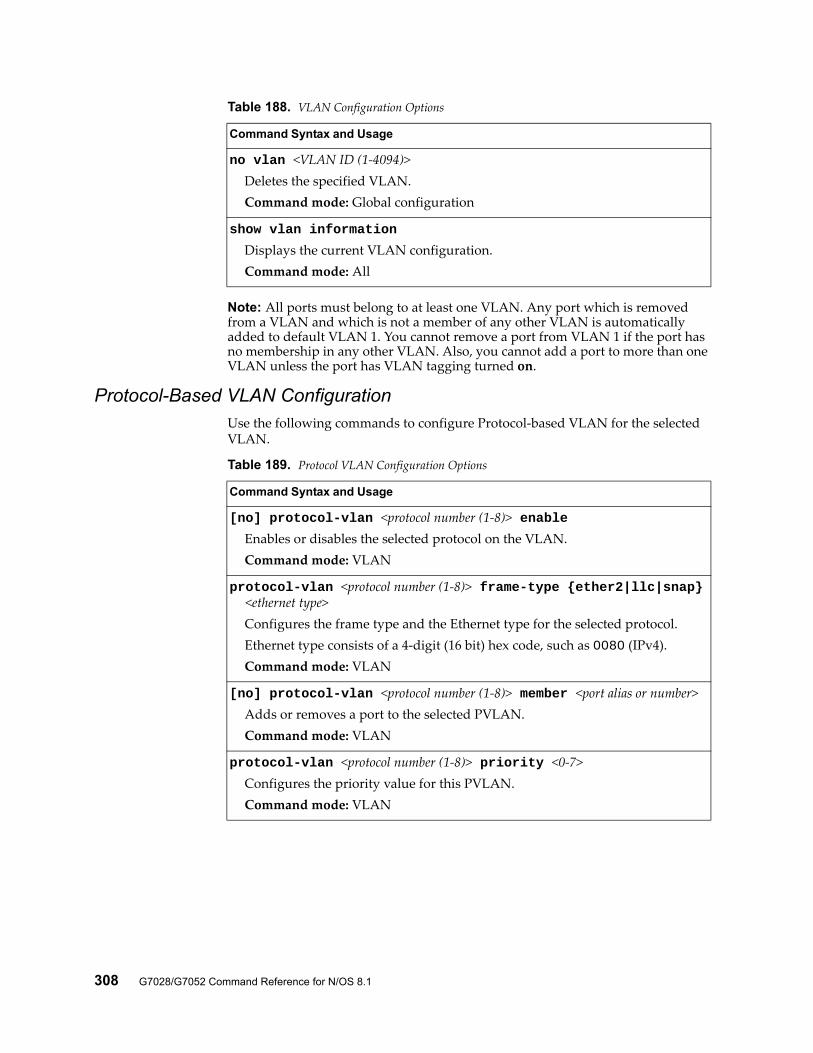
308 G7028/G7052 Command Reference for N/OS 8.1
Note: All ports must belong to at least one VLAN. Any port which is removed from a VLAN and which is not a member of any other VLAN is automatically added to default VLAN 1. You cannot remove a port from VLAN 1 if the port has no membership in any other VLAN. Also, you cannot add a port to more than one VLAN unless the port has VLAN tagging turned on.
Protocol-Based VLAN ConfigurationUse the following commands to configure Protocol-based VLAN for the selected VLAN.
no vlan <VLAN ID (1-4094)>Deletes the specified VLAN.Command mode: Global configuration
show vlan information
Displays the current VLAN configuration.Command mode: All
Table 188. VLAN Configuration Options
Command Syntax and Usage
Table 189. Protocol VLAN Configuration Options
Command Syntax and Usage
[no] protocol-vlan <protocol number (1-8)> enableEnables or disables the selected protocol on the VLAN.Command mode: VLAN
protocol-vlan <protocol number (1-8)> frame-type {ether2|llc|snap} <ethernet type>
Configures the frame type and the Ethernet type for the selected protocol.Ethernet type consists of a 4-digit (16 bit) hex code, such as 0080 (IPv4).Command mode: VLAN
[no] protocol-vlan <protocol number (1-8)> member <port alias or number>Adds or removes a port to the selected PVLAN.Command mode: VLAN
protocol-vlan <protocol number (1-8)> priority <0-7>Configures the priority value for this PVLAN.Command mode: VLAN
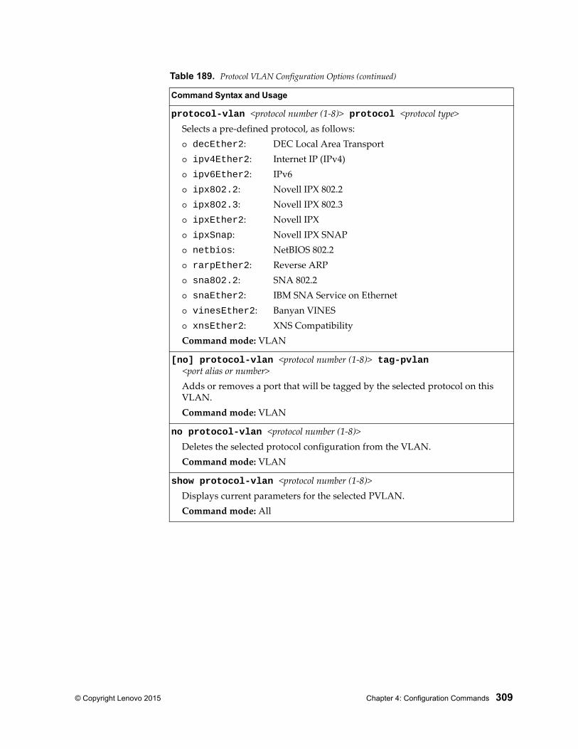
© Copyright Lenovo 2015 Chapter 4: Configuration Commands 309
protocol-vlan <protocol number (1-8)> protocol <protocol type>Selects a pre-defined protocol, as follows: decEther2: DEC Local Area Transport ipv4Ether2: Internet IP (IPv4) ipv6Ether2: IPv6 ipx802.2: Novell IPX 802.2 ipx802.3: Novell IPX 802.3 ipxEther2: Novell IPX ipxSnap: Novell IPX SNAP netbios: NetBIOS 802.2 rarpEther2: Reverse ARP sna802.2: SNA 802.2 snaEther2: IBM SNA Service on Ethernet vinesEther2: Banyan VINES xnsEther2: XNS CompatibilityCommand mode: VLAN
[no] protocol-vlan <protocol number (1-8)> tag-pvlan <port alias or number>
Adds or removes a port that will be tagged by the selected protocol on this VLAN.Command mode: VLAN
no protocol-vlan <protocol number (1-8)>Deletes the selected protocol configuration from the VLAN.Command mode: VLAN
show protocol-vlan <protocol number (1-8)>Displays current parameters for the selected PVLAN.Command mode: All
Table 189. Protocol VLAN Configuration Options (continued)
Command Syntax and Usage
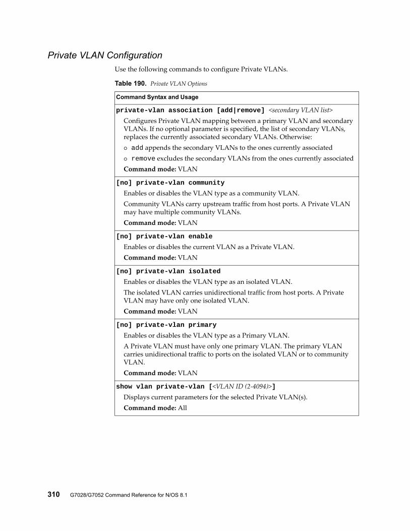
310 G7028/G7052 Command Reference for N/OS 8.1
Private VLAN ConfigurationUse the following commands to configure Private VLANs.
Table 190. Private VLAN Options
Command Syntax and Usage
private-vlan association [add|remove] <secondary VLAN list>Configures Private VLAN mapping between a primary VLAN and secondary VLANs. If no optional parameter is specified, the list of secondary VLANs, replaces the currently associated secondary VLANs. Otherwise: add appends the secondary VLANs to the ones currently associated remove excludes the secondary VLANs from the ones currently associatedCommand mode: VLAN
[no] private-vlan community
Enables or disables the VLAN type as a community VLAN.Community VLANs carry upstream traffic from host ports. A Private VLAN may have multiple community VLANs.Command mode: VLAN
[no] private-vlan enable
Enables or disables the current VLAN as a Private VLAN.Command mode: VLAN
[no] private-vlan isolated
Enables or disables the VLAN type as an isolated VLAN.The isolated VLAN carries unidirectional traffic from host ports. A Private VLAN may have only one isolated VLAN.Command mode: VLAN
[no] private-vlan primary
Enables or disables the VLAN type as a Primary VLAN.A Private VLAN must have only one primary VLAN. The primary VLAN carries unidirectional traffic to ports on the isolated VLAN or to community VLAN.Command mode: VLAN
show vlan private-vlan [<VLAN ID (2-4094)>]Displays current parameters for the selected Private VLAN(s).Command mode: All
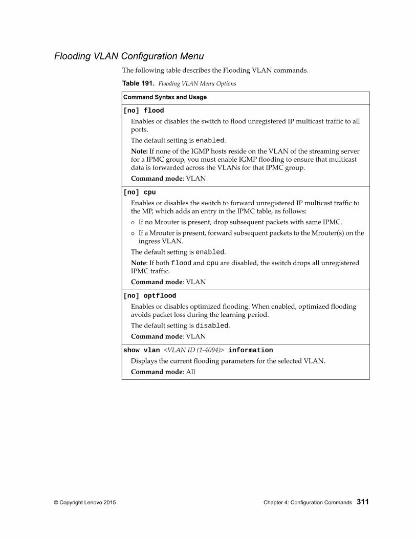
© Copyright Lenovo 2015 Chapter 4: Configuration Commands 311
Flooding VLAN Configuration MenuThe following table describes the Flooding VLAN commands.
Table 191. Flooding VLAN Menu Options
Command Syntax and Usage
[no] flood
Enables or disables the switch to flood unregistered IP multicast traffic to all ports.The default setting is enabled.Note: If none of the IGMP hosts reside on the VLAN of the streaming server for a IPMC group, you must enable IGMP flooding to ensure that multicast data is forwarded across the VLANs for that IPMC group.Command mode: VLAN
[no] cpu
Enables or disables the switch to forward unregistered IP multicast traffic to the MP, which adds an entry in the IPMC table, as follows: If no Mrouter is present, drop subsequent packets with same IPMC. If a Mrouter is present, forward subsequent packets to the Mrouter(s) on the
ingress VLAN.The default setting is enabled.Note: If both flood and cpu are disabled, the switch drops all unregistered IPMC traffic.Command mode: VLAN
[no] optflood
Enables or disables optimized flooding. When enabled, optimized flooding avoids packet loss during the learning period.The default setting is disabled.Command mode: VLAN
show vlan <VLAN ID (1-4094)> informationDisplays the current flooding parameters for the selected VLAN.Command mode: All
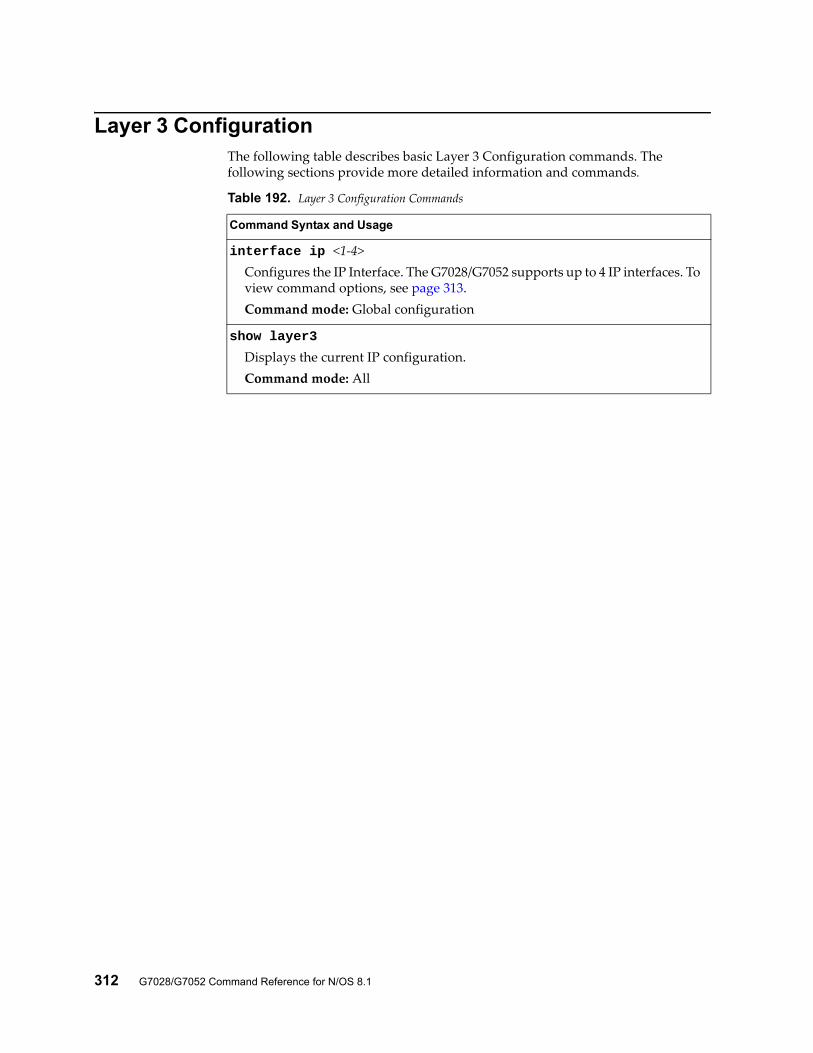
312 G7028/G7052 Command Reference for N/OS 8.1
Layer 3 ConfigurationThe following table describes basic Layer 3 Configuration commands. The following sections provide more detailed information and commands.
Table 192. Layer 3 Configuration Commands
Command Syntax and Usage
interface ip <1-4>Configures the IP Interface. The G7028/G7052 supports up to 4 IP interfaces. To view command options, see page 313.Command mode: Global configuration
show layer3
Displays the current IP configuration.Command mode: All
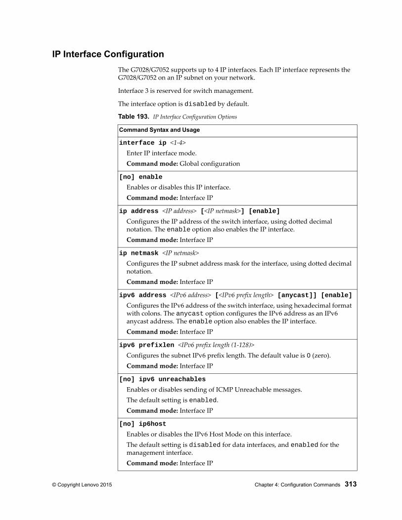
© Copyright Lenovo 2015 Chapter 4: Configuration Commands 313
IP Interface Configuration
The G7028/G7052 supports up to 4 IP interfaces. Each IP interface represents the G7028/G7052 on an IP subnet on your network.
Interface 3 is reserved for switch management.
The interface option is disabled by default.
Table 193. IP Interface Configuration Options
Command Syntax and Usage
interface ip <1-4>Enter IP interface mode.Command mode: Global configuration
[no] enable
Enables or disables this IP interface.Command mode: Interface IP
ip address <IP address> [<IP netmask>] [enable]Configures the IP address of the switch interface, using dotted decimal notation. The enable option also enables the IP interface.Command mode: Interface IP
ip netmask <IP netmask>Configures the IP subnet address mask for the interface, using dotted decimal notation.Command mode: Interface IP
ipv6 address <IPv6 address> [<IPv6 prefix length> [anycast]] [enable]Configures the IPv6 address of the switch interface, using hexadecimal format with colons. The anycast option configures the IPv6 address as an IPv6 anycast address. The enable option also enables the IP interface.Command mode: Interface IP
ipv6 prefixlen <IPv6 prefix length (1-128)>Configures the subnet IPv6 prefix length. The default value is 0 (zero).Command mode: Interface IP
[no] ipv6 unreachables
Enables or disables sending of ICMP Unreachable messages.The default setting is enabled.Command mode: Interface IP
[no] ip6host
Enables or disables the IPv6 Host Mode on this interface.The default setting is disabled for data interfaces, and enabled for the management interface.Command mode: Interface IP
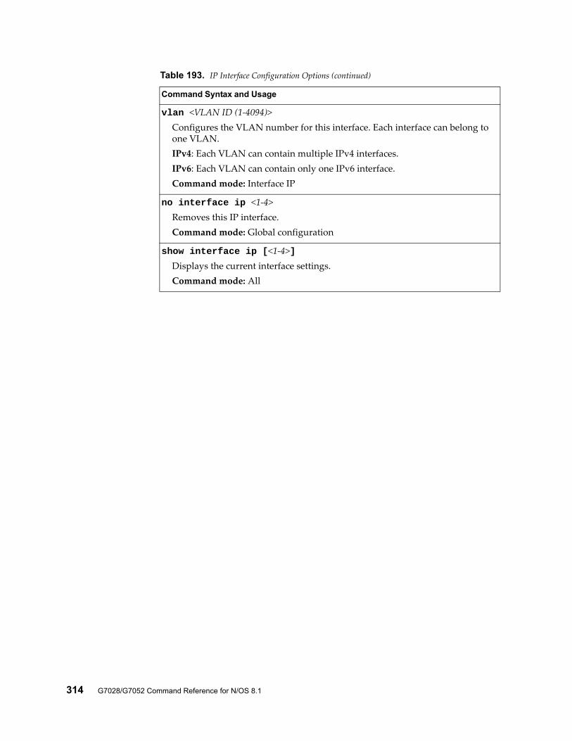
314 G7028/G7052 Command Reference for N/OS 8.1
vlan <VLAN ID (1-4094)>Configures the VLAN number for this interface. Each interface can belong to one VLAN.IPv4: Each VLAN can contain multiple IPv4 interfaces.IPv6: Each VLAN can contain only one IPv6 interface.Command mode: Interface IP
no interface ip <1-4>Removes this IP interface.Command mode: Global configuration
show interface ip [<1-4>]Displays the current interface settings.Command mode: All
Table 193. IP Interface Configuration Options (continued)
Command Syntax and Usage
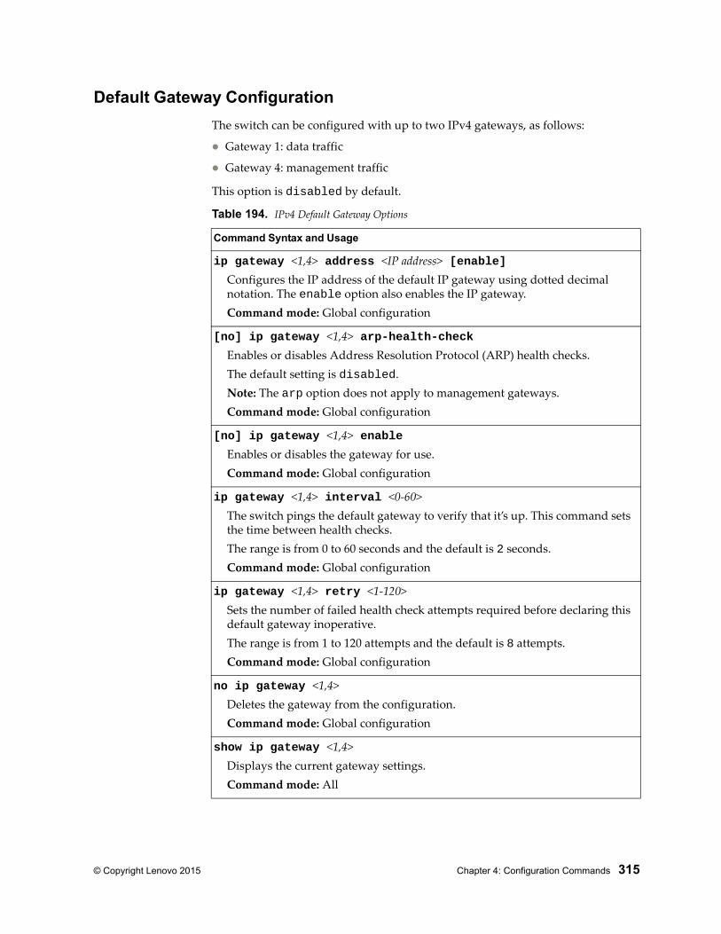
© Copyright Lenovo 2015 Chapter 4: Configuration Commands 315
Default Gateway Configuration
The switch can be configured with up to two IPv4 gateways, as follows:
Gateway 1: data traffic
Gateway 4: management traffic
This option is disabled by default.
Table 194. IPv4 Default Gateway Options
Command Syntax and Usage
ip gateway <1,4> address <IP address> [enable]Configures the IP address of the default IP gateway using dotted decimal notation. The enable option also enables the IP gateway.Command mode: Global configuration
[no] ip gateway <1,4> arp-health-checkEnables or disables Address Resolution Protocol (ARP) health checks.The default setting is disabled.Note: The arp option does not apply to management gateways.Command mode: Global configuration
[no] ip gateway <1,4> enableEnables or disables the gateway for use.Command mode: Global configuration
ip gateway <1,4> interval <0-60>The switch pings the default gateway to verify that it’s up. This command sets the time between health checks.The range is from 0 to 60 seconds and the default is 2 seconds.Command mode: Global configuration
ip gateway <1,4> retry <1-120>Sets the number of failed health check attempts required before declaring this default gateway inoperative.The range is from 1 to 120 attempts and the default is 8 attempts.Command mode: Global configuration
no ip gateway <1,4>Deletes the gateway from the configuration.Command mode: Global configuration
show ip gateway <1,4>Displays the current gateway settings.Command mode: All
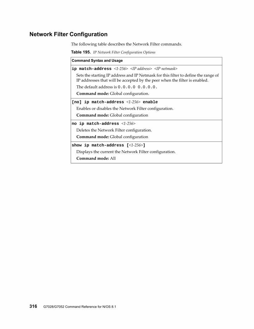
316 G7028/G7052 Command Reference for N/OS 8.1
Network Filter Configuration
The following table describes the Network Filter commands.
Table 195. IP Network Filter Configuration Options
Command Syntax and Usage
ip match-address <1-256> <IP address> <IP netmask>Sets the starting IP address and IP Netmask for this filter to define the range of IP addresses that will be accepted by the peer when the filter is enabled.The default address is 0.0.0.0 0.0.0.0.Command mode: Global configuration.
[no] ip match-address <1-256> enableEnables or disables the Network Filter configuration.Command mode: Global configuration
no ip match-address <1-256>Deletes the Network Filter configuration.Command mode: Global configuration
show ip match-address [<1-256>]Displays the current the Network Filter configuration.Command mode: All
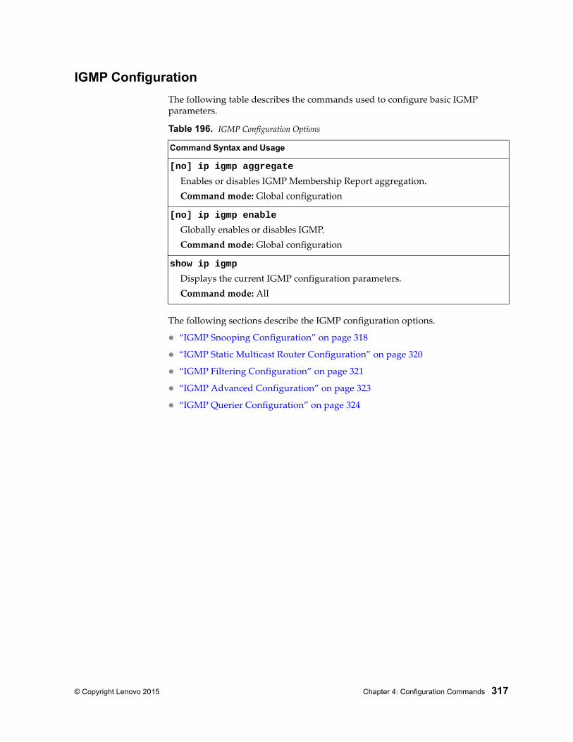
© Copyright Lenovo 2015 Chapter 4: Configuration Commands 317
IGMP Configuration
The following table describes the commands used to configure basic IGMP parameters.
The following sections describe the IGMP configuration options.
“IGMP Snooping Configuration” on page 318
“IGMP Static Multicast Router Configuration” on page 320
“IGMP Filtering Configuration” on page 321
“IGMP Advanced Configuration” on page 323
“IGMP Querier Configuration” on page 324
Table 196. IGMP Configuration Options
Command Syntax and Usage
[no] ip igmp aggregate
Enables or disables IGMP Membership Report aggregation.Command mode: Global configuration
[no] ip igmp enable
Globally enables or disables IGMP.Command mode: Global configuration
show ip igmp
Displays the current IGMP configuration parameters.Command mode: All
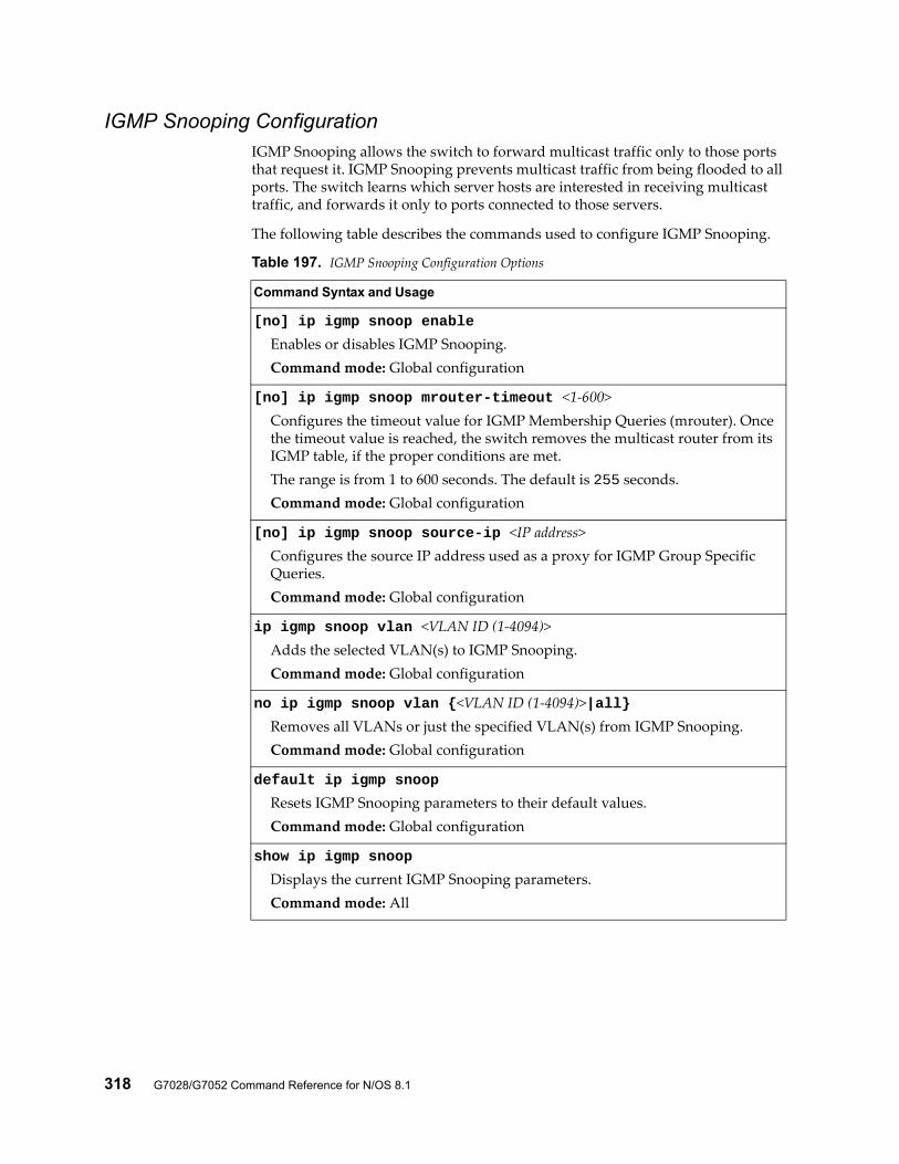
318 G7028/G7052 Command Reference for N/OS 8.1
IGMP Snooping ConfigurationIGMP Snooping allows the switch to forward multicast traffic only to those ports that request it. IGMP Snooping prevents multicast traffic from being flooded to all ports. The switch learns which server hosts are interested in receiving multicast traffic, and forwards it only to ports connected to those servers.
The following table describes the commands used to configure IGMP Snooping.
Table 197. IGMP Snooping Configuration Options
Command Syntax and Usage
[no] ip igmp snoop enable
Enables or disables IGMP Snooping.Command mode: Global configuration
[no] ip igmp snoop mrouter-timeout <1-600>Configures the timeout value for IGMP Membership Queries (mrouter). Once the timeout value is reached, the switch removes the multicast router from its IGMP table, if the proper conditions are met.The range is from 1 to 600 seconds. The default is 255 seconds.Command mode: Global configuration
[no] ip igmp snoop source-ip <IP address>Configures the source IP address used as a proxy for IGMP Group Specific Queries.Command mode: Global configuration
ip igmp snoop vlan <VLAN ID (1-4094)>Adds the selected VLAN(s) to IGMP Snooping.Command mode: Global configuration
no ip igmp snoop vlan {<VLAN ID (1-4094)>|all}Removes all VLANs or just the specified VLAN(s) from IGMP Snooping.Command mode: Global configuration
default ip igmp snoop
Resets IGMP Snooping parameters to their default values.Command mode: Global configuration
show ip igmp snoop
Displays the current IGMP Snooping parameters.Command mode: All
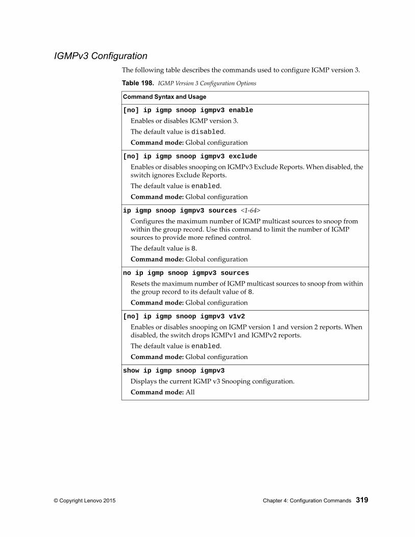
© Copyright Lenovo 2015 Chapter 4: Configuration Commands 319
IGMPv3 ConfigurationThe following table describes the commands used to configure IGMP version 3.
Table 198. IGMP Version 3 Configuration Options
Command Syntax and Usage
[no] ip igmp snoop igmpv3 enable
Enables or disables IGMP version 3.The default value is disabled.Command mode: Global configuration
[no] ip igmp snoop igmpv3 exclude
Enables or disables snooping on IGMPv3 Exclude Reports. When disabled, the switch ignores Exclude Reports.The default value is enabled.Command mode: Global configuration
ip igmp snoop igmpv3 sources <1-64>Configures the maximum number of IGMP multicast sources to snoop from within the group record. Use this command to limit the number of IGMP sources to provide more refined control.The default value is 8.Command mode: Global configuration
no ip igmp snoop igmpv3 sources
Resets the maximum number of IGMP multicast sources to snoop from within the group record to its default value of 8.Command mode: Global configuration
[no] ip igmp snoop igmpv3 v1v2
Enables or disables snooping on IGMP version 1 and version 2 reports. When disabled, the switch drops IGMPv1 and IGMPv2 reports.The default value is enabled.Command mode: Global configuration
show ip igmp snoop igmpv3
Displays the current IGMP v3 Snooping configuration.Command mode: All
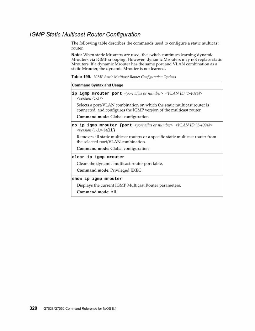
320 G7028/G7052 Command Reference for N/OS 8.1
IGMP Static Multicast Router ConfigurationThe following table describes the commands used to configure a static multicast router.Note: When static Mrouters are used, the switch continues learning dynamic Mrouters via IGMP snooping. However, dynamic Mrouters may not replace static Mrouters. If a dynamic Mrouter has the same port and VLAN combination as a static Mrouter, the dynamic Mrouter is not learned.
Table 199. IGMP Static Multicast Router Configuration Options
Command Syntax and Usage
ip igmp mrouter port <port alias or number> <VLAN ID (1-4094)> <version (1-3)>
Selects a port/VLAN combination on which the static multicast router is connected, and configures the IGMP version of the multicast router.Command mode: Global configuration
no ip igmp mrouter {port <port alias or number> <VLAN ID (1-4094)> <version (1-3)>|all}
Removes all static multicast routers or a specific static multicast router from the selected port/VLAN combination.Command mode: Global configuration
clear ip igmp mrouter
Clears the dynamic multicast router port table.Command mode: Privileged EXEC
show ip igmp mrouter
Displays the current IGMP Multicast Router parameters.Command mode: All
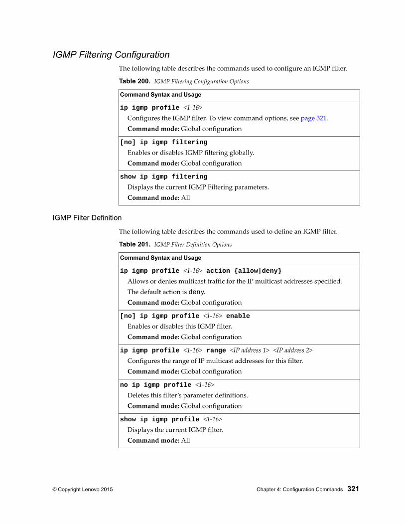
© Copyright Lenovo 2015 Chapter 4: Configuration Commands 321
IGMP Filtering ConfigurationThe following table describes the commands used to configure an IGMP filter.
IGMP Filter Definition
The following table describes the commands used to define an IGMP filter.
Table 200. IGMP Filtering Configuration Options
Command Syntax and Usage
ip igmp profile <1-16>Configures the IGMP filter. To view command options, see page 321.Command mode: Global configuration
[no] ip igmp filtering
Enables or disables IGMP filtering globally.Command mode: Global configuration
show ip igmp filtering
Displays the current IGMP Filtering parameters.Command mode: All
Table 201. IGMP Filter Definition Options
Command Syntax and Usage
ip igmp profile <1-16> action {allow|deny}Allows or denies multicast traffic for the IP multicast addresses specified.The default action is deny.Command mode: Global configuration
[no] ip igmp profile <1-16> enableEnables or disables this IGMP filter.Command mode: Global configuration
ip igmp profile <1-16> range <IP address 1> <IP address 2>Configures the range of IP multicast addresses for this filter.Command mode: Global configuration
no ip igmp profile <1-16>Deletes this filter’s parameter definitions.Command mode: Global configuration
show ip igmp profile <1-16>Displays the current IGMP filter.Command mode: All
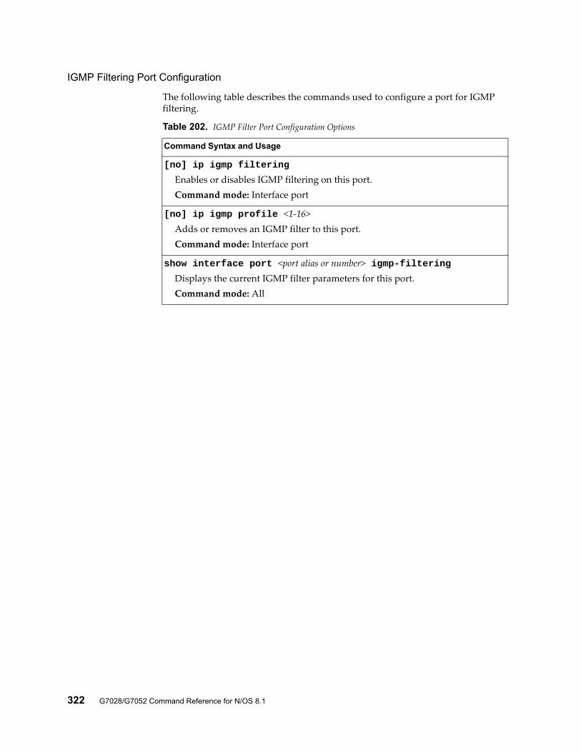
322 G7028/G7052 Command Reference for N/OS 8.1
IGMP Filtering Port Configuration
The following table describes the commands used to configure a port for IGMP filtering.
Table 202. IGMP Filter Port Configuration Options
Command Syntax and Usage
[no] ip igmp filtering
Enables or disables IGMP filtering on this port.Command mode: Interface port
[no] ip igmp profile <1-16>Adds or removes an IGMP filter to this port.Command mode: Interface port
show interface port <port alias or number> igmp-filteringDisplays the current IGMP filter parameters for this port.Command mode: All
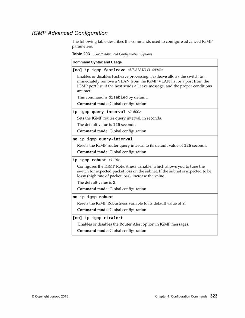
© Copyright Lenovo 2015 Chapter 4: Configuration Commands 323
IGMP Advanced ConfigurationThe following table describes the commands used to configure advanced IGMP parameters.
Table 203. IGMP Advanced Configuration Options
Command Syntax and Usage
[no] ip igmp fastleave <VLAN ID (1-4094)>Enables or disables Fastleave processing. Fastleave allows the switch to immediately remove a VLAN from the IGMP VLAN list or a port from the IGMP port list, if the host sends a Leave message, and the proper conditions are met.This command is disabled by default.Command mode: Global configuration
ip igmp query-interval <1-600>Sets the IGMP router query interval, in seconds.The default value is 125 seconds.Command mode: Global configuration
no ip igmp query-interval
Resets the IGMP router query interval to its default value of 125 seconds.Command mode: Global configuration
ip igmp robust <1-10>Configures the IGMP Robustness variable, which allows you to tune the switch for expected packet loss on the subnet. If the subnet is expected to be lossy (high rate of packet loss), increase the value.The default value is 2.Command mode: Global configuration
no ip igmp robust
Resets the IGMP Robustness variable to its default value of 2.Command mode: Global configuration
[no] ip igmp rtralert
Enables or disables the Router Alert option in IGMP messages.Command mode: Global configuration
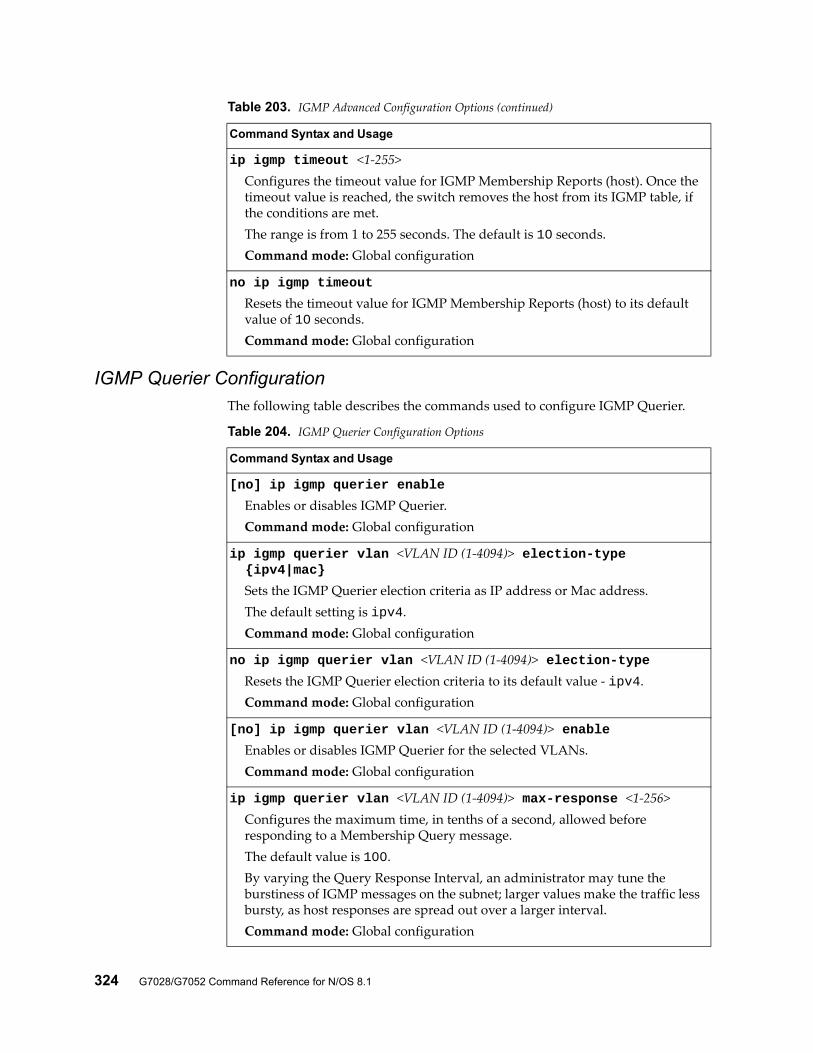
324 G7028/G7052 Command Reference for N/OS 8.1
IGMP Querier ConfigurationThe following table describes the commands used to configure IGMP Querier.
ip igmp timeout <1-255>Configures the timeout value for IGMP Membership Reports (host). Once the timeout value is reached, the switch removes the host from its IGMP table, if the conditions are met.The range is from 1 to 255 seconds. The default is 10 seconds.Command mode: Global configuration
no ip igmp timeout
Resets the timeout value for IGMP Membership Reports (host) to its default value of 10 seconds.Command mode: Global configuration
Table 203. IGMP Advanced Configuration Options (continued)
Command Syntax and Usage
Table 204. IGMP Querier Configuration Options
Command Syntax and Usage
[no] ip igmp querier enable
Enables or disables IGMP Querier.Command mode: Global configuration
ip igmp querier vlan <VLAN ID (1-4094)> election-type {ipv4|mac}
Sets the IGMP Querier election criteria as IP address or Mac address.The default setting is ipv4.Command mode: Global configuration
no ip igmp querier vlan <VLAN ID (1-4094)> election-typeResets the IGMP Querier election criteria to its default value - ipv4.Command mode: Global configuration
[no] ip igmp querier vlan <VLAN ID (1-4094)> enableEnables or disables IGMP Querier for the selected VLANs.Command mode: Global configuration
ip igmp querier vlan <VLAN ID (1-4094)> max-response <1-256>Configures the maximum time, in tenths of a second, allowed before responding to a Membership Query message.The default value is 100.By varying the Query Response Interval, an administrator may tune the burstiness of IGMP messages on the subnet; larger values make the traffic less bursty, as host responses are spread out over a larger interval.Command mode: Global configuration
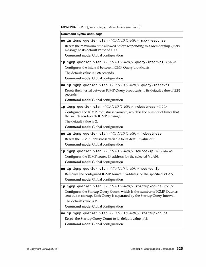
© Copyright Lenovo 2015 Chapter 4: Configuration Commands 325
no ip igmp querier vlan <VLAN ID (1-4094)> max-responseResets the maximum time allowed before responding to a Membership Query message to its default value of 100.Command mode: Global configuration
ip igmp querier vlan <VLAN ID (1-4094)> query-interval <1-608>Configures the interval between IGMP Query broadcasts.The default value is 125 seconds.Command mode: Global configuration
no ip igmp querier vlan <VLAN ID (1-4094)> query-intervalResets the interval between IGMP Query broadcasts to its default value of 125 seconds.Command mode: Global configuration
ip igmp querier vlan <VLAN ID (1-4094)> robustness <1-10>Configures the IGMP Robustness variable, which is the number of times that the switch sends each IGMP message.The default value is 2.Command mode: Global configuration
no ip igmp querier vlan <VLAN ID (1-4094)> robustnessResets the IGMP Robustness variable to its default value of 2.Command mode: Global configuration
ip igmp querier vlan <VLAN ID (1-4094)> source-ip <IP address>Configures the IGMP source IP address for the selected VLAN.Command mode: Global configuration
no ip igmp querier vlan <VLAN ID (1-4094)> source-ipRemoves the configured IGMP source IP address for the specified VLAN.Command mode: Global configuration
ip igmp querier vlan <VLAN ID (1-4094)> startup-count <1-10>Configures the Startup Query Count, which is the number of IGMP Queries sent out at startup. Each Query is separated by the Startup Query Interval.The default value is 2.Command mode: Global configuration
no ip igmp querier vlan <VLAN ID (1-4094)> startup-countResets the Startup Query Count to its default value of 2.Command mode: Global configuration
Table 204. IGMP Querier Configuration Options (continued)
Command Syntax and Usage
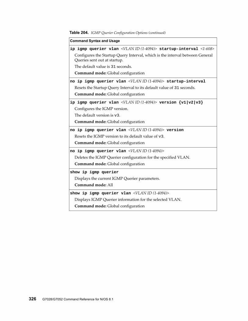
326 G7028/G7052 Command Reference for N/OS 8.1
ip igmp querier vlan <VLAN ID (1-4094)> startup-interval <1-608>Configures the Startup Query Interval, which is the interval between General Queries sent out at startup.The default value is 31 seconds.Command mode: Global configuration
no ip igmp querier vlan <VLAN ID (1-4094)> startup-intervalResets the Startup Query Interval to its default value of 31 seconds.Command mode: Global configuration
ip igmp querier vlan <VLAN ID (1-4094)> version {v1|v2|v3}Configures the IGMP version.The default version is v3.Command mode: Global configuration
no ip igmp querier vlan <VLAN ID (1-4094)> versionResets the IGMP version to its default value of v3.Command mode: Global configuration
no ip igmp querier vlan <VLAN ID (1-4094)>Deletes the IGMP Querier configuration for the specified VLAN.Command mode: Global configuration
show ip igmp querier
Displays the current IGMP Querier parameters.Command mode: All
show ip igmp querier vlan <VLAN ID (1-4094)>Displays IGMP Querier information for the selected VLAN.Command mode: Global configuration
Table 204. IGMP Querier Configuration Options (continued)
Command Syntax and Usage
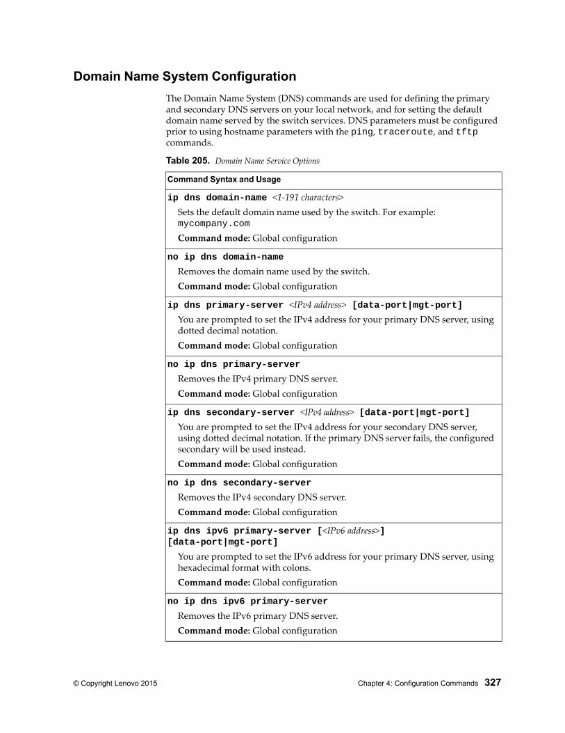
© Copyright Lenovo 2015 Chapter 4: Configuration Commands 327
Domain Name System Configuration
The Domain Name System (DNS) commands are used for defining the primary and secondary DNS servers on your local network, and for setting the default domain name served by the switch services. DNS parameters must be configured prior to using hostname parameters with the ping, traceroute, and tftp commands.
Table 205. Domain Name Service Options
Command Syntax and Usage
ip dns domain-name <1-191 characters>Sets the default domain name used by the switch. For example: mycompany.com
Command mode: Global configuration
no ip dns domain-name
Removes the domain name used by the switch.Command mode: Global configuration
ip dns primary-server <IPv4 address> [data-port|mgt-port]You are prompted to set the IPv4 address for your primary DNS server, using dotted decimal notation.Command mode: Global configuration
no ip dns primary-server
Removes the IPv4 primary DNS server.Command mode: Global configuration
ip dns secondary-server <IPv4 address> [data-port|mgt-port]You are prompted to set the IPv4 address for your secondary DNS server, using dotted decimal notation. If the primary DNS server fails, the configured secondary will be used instead.Command mode: Global configuration
no ip dns secondary-server
Removes the IPv4 secondary DNS server.Command mode: Global configuration
ip dns ipv6 primary-server [<IPv6 address>] [data-port|mgt-port]
You are prompted to set the IPv6 address for your primary DNS server, using hexadecimal format with colons.Command mode: Global configuration
no ip dns ipv6 primary-server
Removes the IPv6 primary DNS server.Command mode: Global configuration
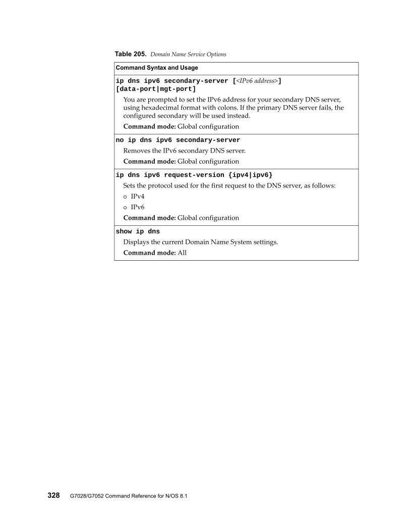
328 G7028/G7052 Command Reference for N/OS 8.1
ip dns ipv6 secondary-server [<IPv6 address>] [data-port|mgt-port]
You are prompted to set the IPv6 address for your secondary DNS server, using hexadecimal format with colons. If the primary DNS server fails, the configured secondary will be used instead.Command mode: Global configuration
no ip dns ipv6 secondary-server
Removes the IPv6 secondary DNS server.Command mode: Global configuration
ip dns ipv6 request-version {ipv4|ipv6}
Sets the protocol used for the first request to the DNS server, as follows: IPv4 IPv6Command mode: Global configuration
show ip dns
Displays the current Domain Name System settings.Command mode: All
Table 205. Domain Name Service Options
Command Syntax and Usage
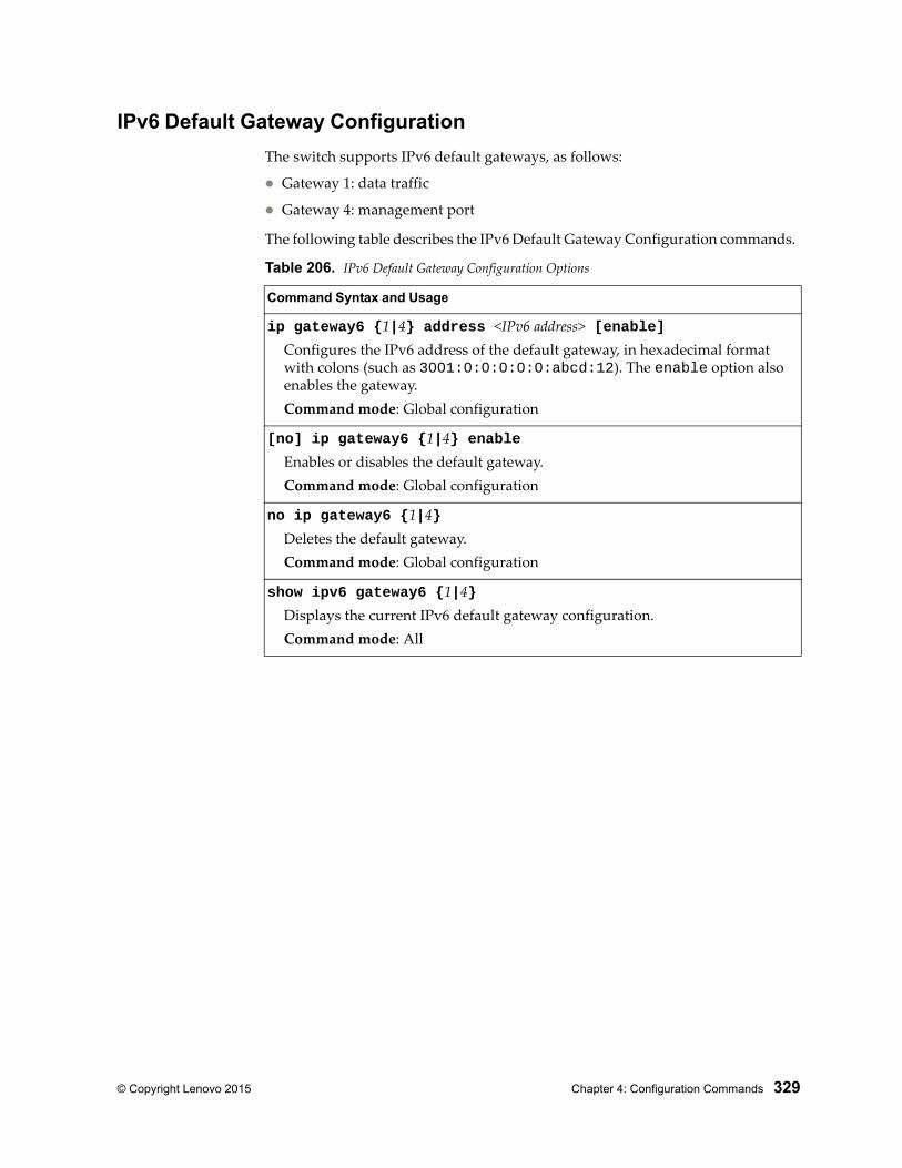
© Copyright Lenovo 2015 Chapter 4: Configuration Commands 329
IPv6 Default Gateway Configuration
The switch supports IPv6 default gateways, as follows:
Gateway 1: data traffic
Gateway 4: management port
The following table describes the IPv6 Default Gateway Configuration commands.
Table 206. IPv6 Default Gateway Configuration Options
Command Syntax and Usage
ip gateway6 {1|4} address <IPv6 address> [enable]Configures the IPv6 address of the default gateway, in hexadecimal format with colons (such as 3001:0:0:0:0:0:abcd:12). The enable option also enables the gateway.Command mode: Global configuration
[no] ip gateway6 {1|4} enableEnables or disables the default gateway.Command mode: Global configuration
no ip gateway6 {1|4}Deletes the default gateway.Command mode: Global configuration
show ipv6 gateway6 {1|4}Displays the current IPv6 default gateway configuration.Command mode: All
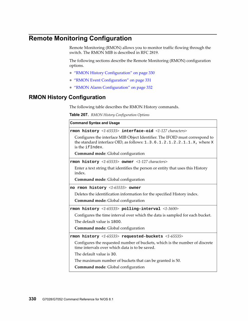
330 G7028/G7052 Command Reference for N/OS 8.1
Remote Monitoring ConfigurationRemote Monitoring (RMON) allows you to monitor traffic flowing through the switch. The RMON MIB is described in RFC 2819.
The following sections describe the Remote Monitoring (RMON) configuration options.
“RMON History Configuration” on page 330
“RMON Event Configuration” on page 331
“RMON Alarm Configuration” on page 332
RMON History Configuration
The following table describes the RMON History commands.
Table 207. RMON History Configuration Options
Command Syntax and Usage
rmon history <1-65535> interface-oid <1-127 characters>Configures the interface MIB Object Identifier. The IFOID must correspond to the standard interface OID, as follows: 1.3.6.1.2.1.2.2.1.1.X, where X is the ifIndex.Command mode: Global configuration
rmon history <1-65535> owner <1-127 characters>Enter a text string that identifies the person or entity that uses this History index.Command mode: Global configuration
no rmon history <1-65535> ownerDeletes the identification information for the specified History index.Command mode: Global configuration
rmon history <1-65535> polling-interval <1-3600>Configures the time interval over which the data is sampled for each bucket.The default value is 1800.Command mode: Global configuration
rmon history <1-65535> requested-buckets <1-65535>Configures the requested number of buckets, which is the number of discrete time intervals over which data is to be saved.The default value is 30.The maximum number of buckets that can be granted is 50.Command mode: Global configuration
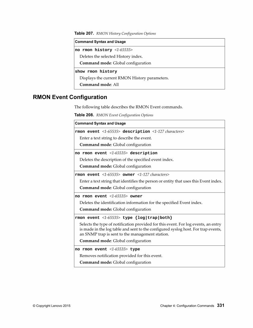
© Copyright Lenovo 2015 Chapter 4: Configuration Commands 331
RMON Event Configuration
The following table describes the RMON Event commands.
no rmon history <1-65535>Deletes the selected History index.Command mode: Global configuration
show rmon history
Displays the current RMON History parameters.Command mode: All
Table 207. RMON History Configuration Options
Command Syntax and Usage
Table 208. RMON Event Configuration Options
Command Syntax and Usage
rmon event <1-65535> description <1-127 characters>Enter a text string to describe the event.Command mode: Global configuration
no rmon event <1-65535> descriptionDeletes the description of the specified event index.Command mode: Global configuration
rmon event <1-65535> owner <1-127 characters>Enter a text string that identifies the person or entity that uses this Event index.Command mode: Global configuration
no rmon event <1-65535> ownerDeletes the identification information for the specified Event index.Command mode: Global configuration
rmon event <1-65535> type {log|trap|both}Selects the type of notification provided for this event. For log events, an entry is made in the log table and sent to the configured syslog host. For trap events, an SNMP trap is sent to the management station.Command mode: Global configuration
no rmon event <1-65535> typeRemoves notification provided for this event.Command mode: Global configuration
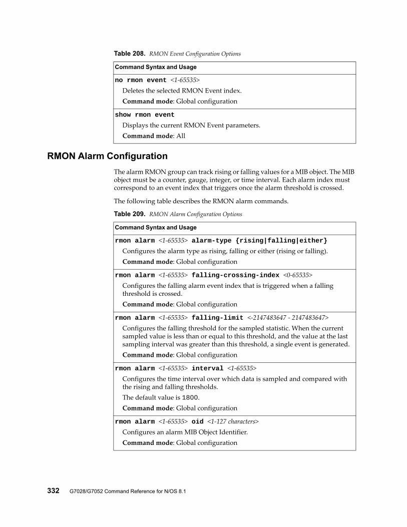
332 G7028/G7052 Command Reference for N/OS 8.1
RMON Alarm Configuration
The alarm RMON group can track rising or falling values for a MIB object. The MIB object must be a counter, gauge, integer, or time interval. Each alarm index must correspond to an event index that triggers once the alarm threshold is crossed.
The following table describes the RMON alarm commands.
no rmon event <1-65535>Deletes the selected RMON Event index. Command mode: Global configuration
show rmon event
Displays the current RMON Event parameters.Command mode: All
Table 208. RMON Event Configuration Options
Command Syntax and Usage
Table 209. RMON Alarm Configuration Options
Command Syntax and Usage
rmon alarm <1-65535> alarm-type {rising|falling|either}Configures the alarm type as rising, falling or either (rising or falling).Command mode: Global configuration
rmon alarm <1-65535> falling-crossing-index <0-65535>Configures the falling alarm event index that is triggered when a falling threshold is crossed.Command mode: Global configuration
rmon alarm <1-65535> falling-limit <-2147483647 - 2147483647>Configures the falling threshold for the sampled statistic. When the current sampled value is less than or equal to this threshold, and the value at the last sampling interval was greater than this threshold, a single event is generated.Command mode: Global configuration
rmon alarm <1-65535> interval <1-65535>Configures the time interval over which data is sampled and compared with the rising and falling thresholds.The default value is 1800.Command mode: Global configuration
rmon alarm <1-65535> oid <1-127 characters>Configures an alarm MIB Object Identifier.Command mode: Global configuration
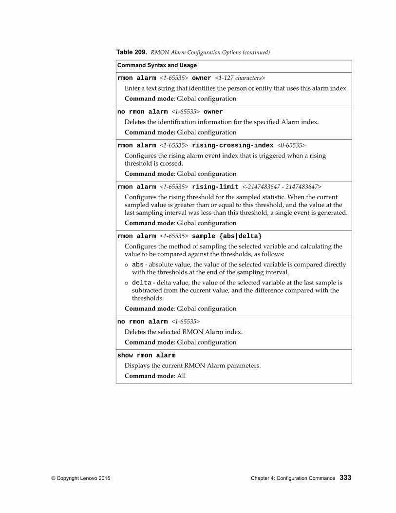
© Copyright Lenovo 2015 Chapter 4: Configuration Commands 333
rmon alarm <1-65535> owner <1-127 characters>Enter a text string that identifies the person or entity that uses this alarm index.Command mode: Global configuration
no rmon alarm <1-65535> ownerDeletes the identification information for the specified Alarm index.Command mode: Global configuration
rmon alarm <1-65535> rising-crossing-index <0-65535>Configures the rising alarm event index that is triggered when a rising threshold is crossed.Command mode: Global configuration
rmon alarm <1-65535> rising-limit <-2147483647 - 2147483647>Configures the rising threshold for the sampled statistic. When the current sampled value is greater than or equal to this threshold, and the value at the last sampling interval was less than this threshold, a single event is generated.Command mode: Global configuration
rmon alarm <1-65535> sample {abs|delta}Configures the method of sampling the selected variable and calculating the value to be compared against the thresholds, as follows: abs - absolute value, the value of the selected variable is compared directly
with the thresholds at the end of the sampling interval. delta - delta value, the value of the selected variable at the last sample is
subtracted from the current value, and the difference compared with the thresholds.
Command mode: Global configuration
no rmon alarm <1-65535>Deletes the selected RMON Alarm index.Command mode: Global configuration
show rmon alarm
Displays the current RMON Alarm parameters.Command mode: All
Table 209. RMON Alarm Configuration Options (continued)
Command Syntax and Usage
334 G7028/G7052 Command Reference for N/OS 8.1
Configuration DumpThe dump program writes the current switch configuration to the terminal screen. To start the dump program, at the prompt, enter:
The configuration is displayed with parameters that have been changed from the default values. The screen display can be captured, edited, and placed in a script file, which can be used to configure other switches through a Telnet connection. When using Telnet to configure a new switch, paste the configuration commands from the script file at the command line prompt of the switch. The active configuration can also be saved or loaded via FTP/TFTP, as described on page 335.
RS G7052# show running-config
© Copyright Lenovo 2015 Chapter 4: Configuration Commands 335
Saving the Active Switch ConfigurationWhen the copy running-config command is used, the switch’s active configuration commands (as displayed using show running-config) will be uploaded to the specified script configuration file on the FTP/TFTP server. To start the switch configuration upload, at the prompt, enter:
or:
The switch prompts you for the server address and filename.Note: The output file is formatted with line-breaks but no carriage returns—the file cannot be viewed with editors that require carriage returns (such as Microsoft Notepad).
Note: If the FTP/TFTP server is running SunOS or the Solaris operating system, the specified configuration file must exist prior to executing the copy running-config command and must be writable (set with proper permission, and not locked by any application). The contents of the specified file will be replaced with the current configuration data.
RS G7052# copy running-config ftp
RS G7052# copy running-config tftp
336 G7028/G7052 Command Reference for N/OS 8.1
Restoring the Active Switch ConfigurationWhen the copy running-config command is used, the active configuration will be replaced with the commands found in the specified configuration file. The file can contain a full switch configuration or a partial switch configuration.
To start the switch configuration download, at the prompt, enter:
or:
The switch prompts you for the server address and filename.
RS G7052# copy ftp running-config
RS G7052# copy tftp running-config
© Copyright Lenovo 2015 Chapter 4: Configuration Commands 337
USB CopyIf a USB drive is inserted into the USB port, you can copy files from the switch to the USB drive, or from the USB drive to the switch. You also can boot the switch using software or configuration files found on the USB drive (see “USB Boot Configuration” on page 344).
Copy to USB
Use the following command to copy a file from the switch to the USB drive:
usbcopy tousb <filename> {active|boot|crashdump|image1|image2||syslog}
Command mode: Privileged EXEC
In this example, the active configuration file is copied to a directory on the USB drive:
Copy from USB
Use the following command to copy a file from the USB drive to the switch:
usbcopy fromusb <filename> {active|boot|image1|image2}
Command mode: Privileged EXEC
In this example, the active configuration file is copied from a directory on the USB drive:
The new file replaces the current file.Note: Do not use two consecutive dot characters ( .. ). Do not use a slash character ( / ) to begin a filename.
RS G7052# usbcopy tousb a_folder/myconfig.cfg active
RS G7052# usbcopy fromusb a_folder/myconfig.cfg active

338 G7028/G7052 Command Reference for N/OS 8.1
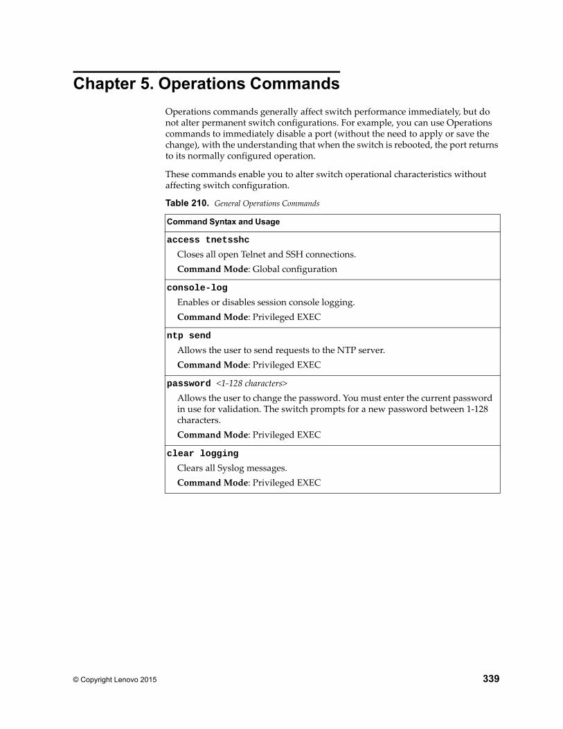
© Copyright Lenovo 2015 339
Chapter 5. Operations Commands
Operations commands generally affect switch performance immediately, but do not alter permanent switch configurations. For example, you can use Operations commands to immediately disable a port (without the need to apply or save the change), with the understanding that when the switch is rebooted, the port returns to its normally configured operation.
These commands enable you to alter switch operational characteristics without affecting switch configuration.
Table 210. General Operations Commands
Command Syntax and Usage
access tnetsshc
Closes all open Telnet and SSH connections.Command Mode: Global configuration
console-log
Enables or disables session console logging.Command Mode: Privileged EXEC
ntp send
Allows the user to send requests to the NTP server.Command Mode: Privileged EXEC
password <1-128 characters>Allows the user to change the password. You must enter the current password in use for validation. The switch prompts for a new password between 1-128 characters.Command Mode: Privileged EXEC
clear logging
Clears all Syslog messages.Command Mode: Privileged EXEC
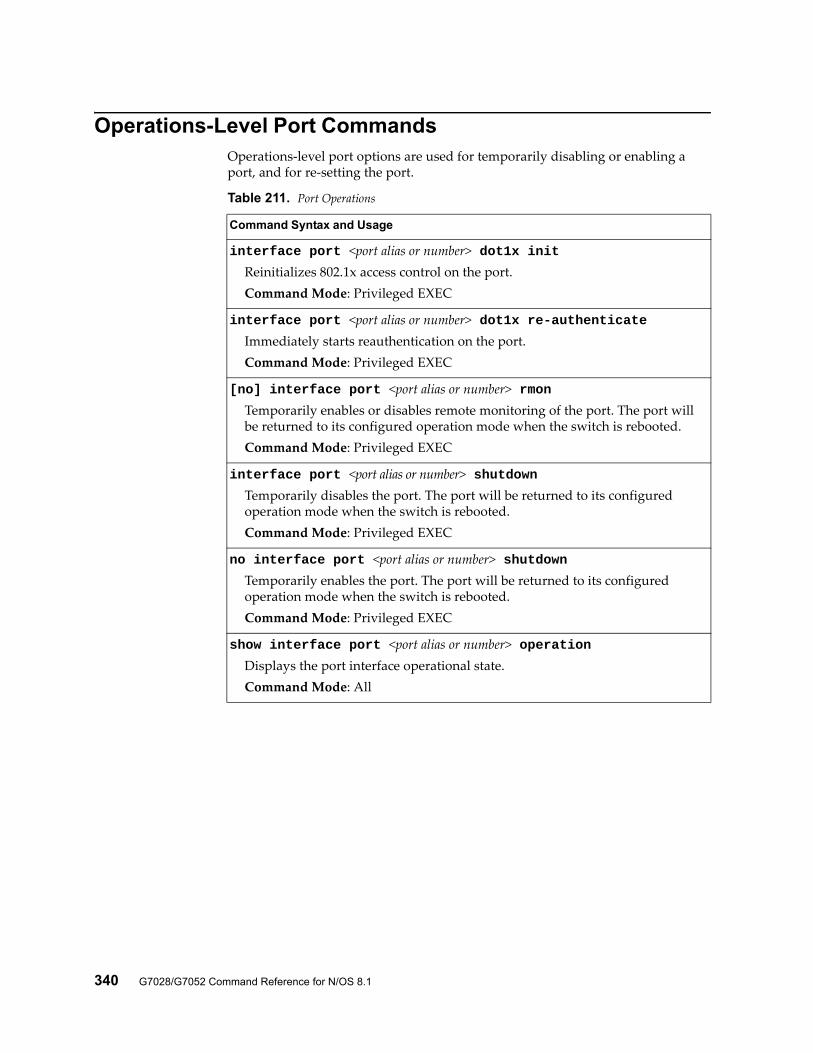
340 G7028/G7052 Command Reference for N/OS 8.1
Operations-Level Port CommandsOperations-level port options are used for temporarily disabling or enabling a port, and for re-setting the port.
Table 211. Port Operations
Command Syntax and Usage
interface port <port alias or number> dot1x initReinitializes 802.1x access control on the port.Command Mode: Privileged EXEC
interface port <port alias or number> dot1x re-authenticateImmediately starts reauthentication on the port.Command Mode: Privileged EXEC
[no] interface port <port alias or number> rmonTemporarily enables or disables remote monitoring of the port. The port will be returned to its configured operation mode when the switch is rebooted.Command Mode: Privileged EXEC
interface port <port alias or number> shutdownTemporarily disables the port. The port will be returned to its configured operation mode when the switch is rebooted.Command Mode: Privileged EXEC
no interface port <port alias or number> shutdownTemporarily enables the port. The port will be returned to its configured operation mode when the switch is rebooted.Command Mode: Privileged EXEC
show interface port <port alias or number> operationDisplays the port interface operational state.Command Mode: All
© Copyright Lenovo 2015 341
Chapter 6. Boot Options
To use the Boot Options commands, you must be logged in to the switch as the administrator. The Boot Options commands provide options for:
Selecting a switch software image to be used when the switch on the next reboot
Selecting a configuration block to be used when the switch on the next reboot
Downloading or uploading a new software image to the switch via FTP/TFTP
In addition to the Boot commands, you can use a Web browser or SNMP to work with switch image and configuration files. To use SNMP, refer to “Working with Switch Images and Configuration Files”.
The boot options are discussed in the following sections.
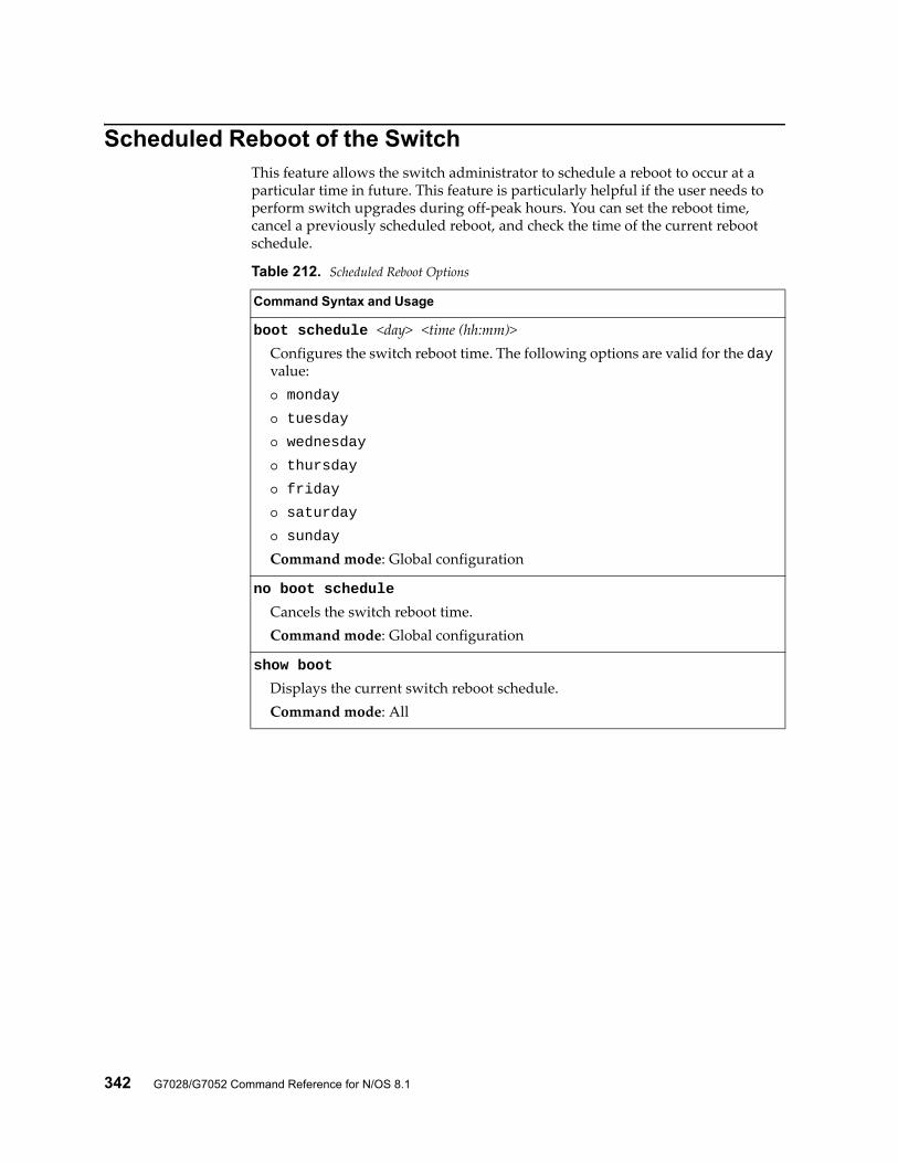
342 G7028/G7052 Command Reference for N/OS 8.1
Scheduled Reboot of the SwitchThis feature allows the switch administrator to schedule a reboot to occur at a particular time in future. This feature is particularly helpful if the user needs to perform switch upgrades during off-peak hours. You can set the reboot time, cancel a previously scheduled reboot, and check the time of the current reboot schedule.
Table 212. Scheduled Reboot Options
Command Syntax and Usage
boot schedule <day> <time (hh:mm)>Configures the switch reboot time. The following options are valid for the day value: monday
tuesday
wednesday
thursday
friday
saturday
sunday
Command mode: Global configuration
no boot schedule
Cancels the switch reboot time.Command mode: Global configuration
show boot
Displays the current switch reboot schedule.Command mode: All
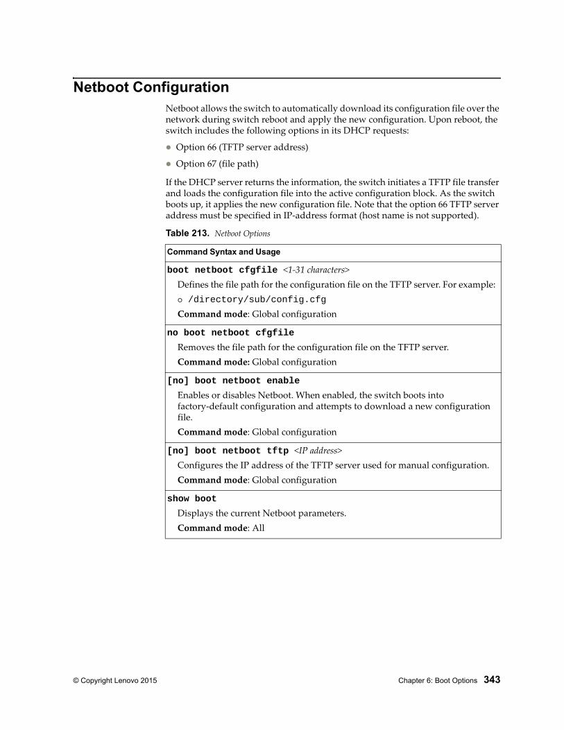
© Copyright Lenovo 2015 Chapter 6: Boot Options 343
Netboot ConfigurationNetboot allows the switch to automatically download its configuration file over the network during switch reboot and apply the new configuration. Upon reboot, the switch includes the following options in its DHCP requests:
Option 66 (TFTP server address)
Option 67 (file path)
If the DHCP server returns the information, the switch initiates a TFTP file transfer and loads the configuration file into the active configuration block. As the switch boots up, it applies the new configuration file. Note that the option 66 TFTP server address must be specified in IP-address format (host name is not supported).
Table 213. Netboot Options
Command Syntax and Usage
boot netboot cfgfile <1-31 characters>Defines the file path for the configuration file on the TFTP server. For example: /directory/sub/config.cfg
Command mode: Global configuration
no boot netboot cfgfile
Removes the file path for the configuration file on the TFTP server.Command mode: Global configuration
[no] boot netboot enable
Enables or disables Netboot. When enabled, the switch boots into factory-default configuration and attempts to download a new configuration file.Command mode: Global configuration
[no] boot netboot tftp <IP address>Configures the IP address of the TFTP server used for manual configuration. Command mode: Global configuration
show boot
Displays the current Netboot parameters.Command mode: All
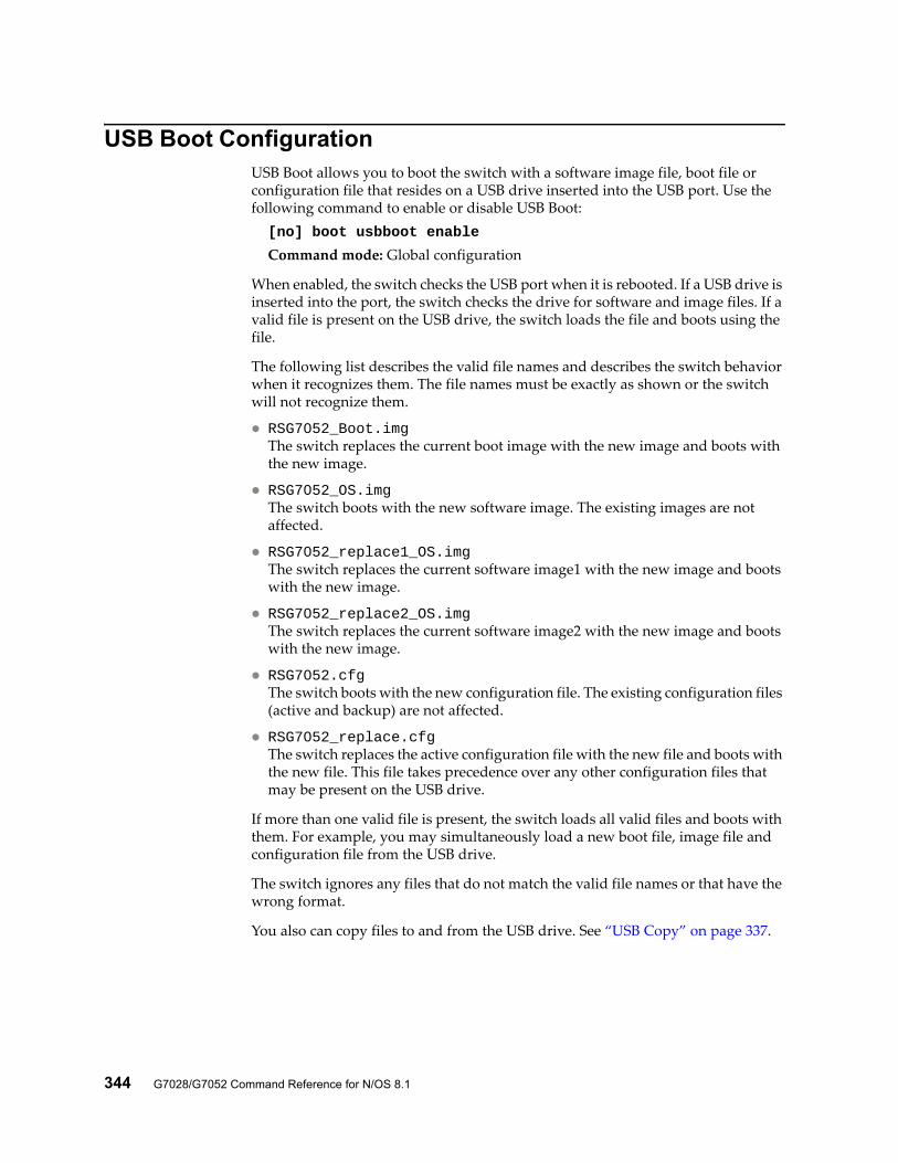
344 G7028/G7052 Command Reference for N/OS 8.1
USB Boot ConfigurationUSB Boot allows you to boot the switch with a software image file, boot file or configuration file that resides on a USB drive inserted into the USB port. Use the following command to enable or disable USB Boot:[no] boot usbboot enable
Command mode: Global configuration
When enabled, the switch checks the USB port when it is rebooted. If a USB drive is inserted into the port, the switch checks the drive for software and image files. If a valid file is present on the USB drive, the switch loads the file and boots using the file.
The following list describes the valid file names and describes the switch behavior when it recognizes them. The file names must be exactly as shown or the switch will not recognize them.
RSG7052_Boot.imgThe switch replaces the current boot image with the new image and boots with the new image.
RSG7052_OS.imgThe switch boots with the new software image. The existing images are not affected.
RSG7052_replace1_OS.imgThe switch replaces the current software image1 with the new image and boots with the new image.
RSG7052_replace2_OS.imgThe switch replaces the current software image2 with the new image and boots with the new image.
RSG7052.cfgThe switch boots with the new configuration file. The existing configuration files (active and backup) are not affected.
RSG7052_replace.cfgThe switch replaces the active configuration file with the new file and boots with the new file. This file takes precedence over any other configuration files that may be present on the USB drive.
If more than one valid file is present, the switch loads all valid files and boots with them. For example, you may simultaneously load a new boot file, image file and configuration file from the USB drive.
The switch ignores any files that do not match the valid file names or that have the wrong format.
You also can copy files to and from the USB drive. See “USB Copy” on page 337.
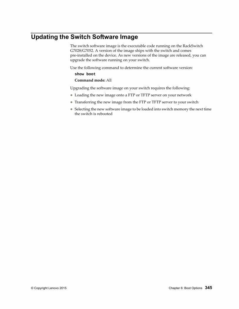
© Copyright Lenovo 2015 Chapter 6: Boot Options 345
Updating the Switch Software ImageThe switch software image is the executable code running on the RackSwitch G7028/G7052. A version of the image ships with the switch and comes pre-installed on the device. As new versions of the image are released, you can upgrade the software running on your switch.
Use the following command to determine the current software version:show boot
Command mode: All
Upgrading the software image on your switch requires the following:
Loading the new image onto a FTP or TFTP server on your network
Transferring the new image from the FTP or TFTP server to your switch
Selecting the new software image to be loaded into switch memory the next time the switch is rebooted
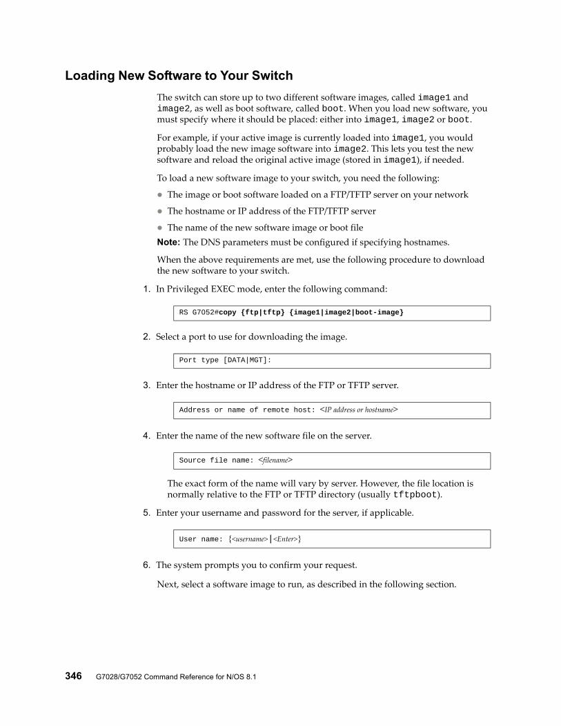
346 G7028/G7052 Command Reference for N/OS 8.1
Loading New Software to Your Switch
The switch can store up to two different software images, called image1 and image2, as well as boot software, called boot. When you load new software, you must specify where it should be placed: either into image1, image2 or boot.
For example, if your active image is currently loaded into image1, you would probably load the new image software into image2. This lets you test the new software and reload the original active image (stored in image1), if needed.
To load a new software image to your switch, you need the following:
The image or boot software loaded on a FTP/TFTP server on your network
The hostname or IP address of the FTP/TFTP server
The name of the new software image or boot fileNote: The DNS parameters must be configured if specifying hostnames.
When the above requirements are met, use the following procedure to download the new software to your switch.
1. In Privileged EXEC mode, enter the following command:
2. Select a port to use for downloading the image.
3. Enter the hostname or IP address of the FTP or TFTP server.
4. Enter the name of the new software file on the server.
The exact form of the name will vary by server. However, the file location is normally relative to the FTP or TFTP directory (usually tftpboot).
5. Enter your username and password for the server, if applicable.
6. The system prompts you to confirm your request.
Next, select a software image to run, as described in the following section.
RS G7052#copy {ftp|tftp} {image1|image2|boot-image}
Port type [DATA|MGT]:
Address or name of remote host: <IP address or hostname>
Source file name: <filename>
User name: {<username>|<Enter>}
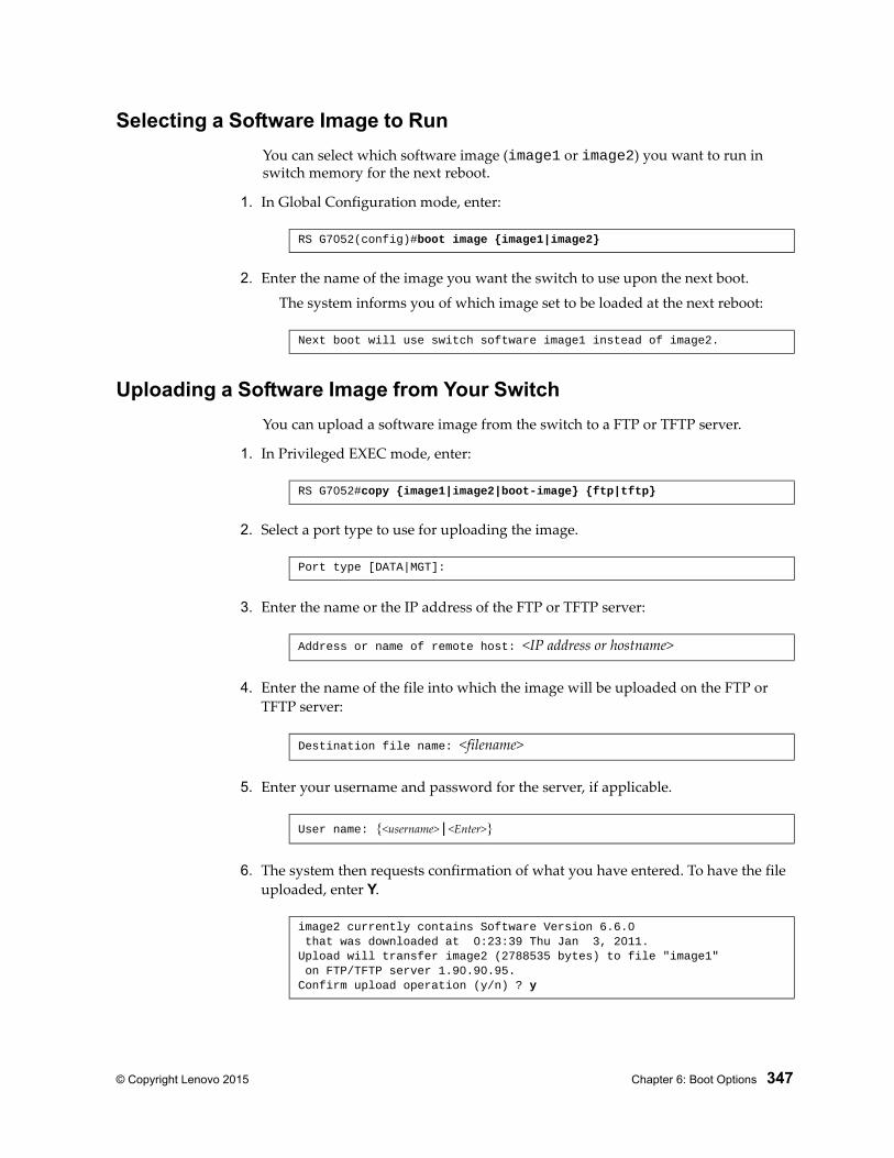
© Copyright Lenovo 2015 Chapter 6: Boot Options 347
Selecting a Software Image to Run
You can select which software image (image1 or image2) you want to run in switch memory for the next reboot.
1. In Global Configuration mode, enter:
2. Enter the name of the image you want the switch to use upon the next boot.
The system informs you of which image set to be loaded at the next reboot:
Uploading a Software Image from Your Switch
You can upload a software image from the switch to a FTP or TFTP server.
1. In Privileged EXEC mode, enter:
2. Select a port type to use for uploading the image.
3. Enter the name or the IP address of the FTP or TFTP server:
4. Enter the name of the file into which the image will be uploaded on the FTP or TFTP server:
5. Enter your username and password for the server, if applicable.
6. The system then requests confirmation of what you have entered. To have the file uploaded, enter Y.
RS G7052(config)#boot image {image1|image2}
Next boot will use switch software image1 instead of image2.
RS G7052#copy {image1|image2|boot-image} {ftp|tftp}
Port type [DATA|MGT]:
Address or name of remote host: <IP address or hostname>
Destination file name: <filename>
User name: {<username>|<Enter>}
image2 currently contains Software Version 6.6.0 that was downloaded at 0:23:39 Thu Jan 3, 2011.Upload will transfer image2 (2788535 bytes) to file "image1" on FTP/TFTP server 1.90.90.95.Confirm upload operation (y/n) ? y
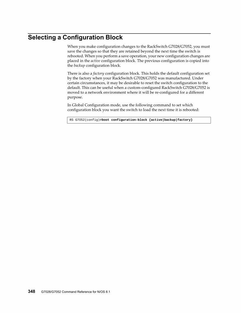
348 G7028/G7052 Command Reference for N/OS 8.1
Selecting a Configuration BlockWhen you make configuration changes to the RackSwitch G7028/G7052, you must save the changes so that they are retained beyond the next time the switch is rebooted. When you perform a save operation, your new configuration changes are placed in the active configuration block. The previous configuration is copied into the backup configuration block.
There is also a factory configuration block. This holds the default configuration set by the factory when your RackSwitch G7028/G7052 was manufactured. Under certain circumstances, it may be desirable to reset the switch configuration to the default. This can be useful when a custom-configured RackSwitch G7028/G7052 is moved to a network environment where it will be re-configured for a different purpose.
In Global Configuration mode, use the following command to set which configuration block you want the switch to load the next time it is rebooted:
RS G7052(config)#boot configuration-block {active|backup|factory}
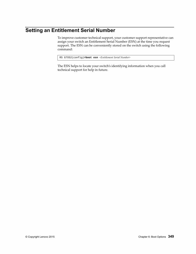
© Copyright Lenovo 2015 Chapter 6: Boot Options 349
Setting an Entitlement Serial NumberTo improve customer technical support, your customer support representative can assign your switch an Entitlement Serial Number (ESN) at the time you request support. The ESN can be conveniently stored on the switch using the following command:
The ESN helps to locate your switch’s identifying information when you call technical support for help in future.
RS G7052(config)#boot esn <Entitlement Serial Number>
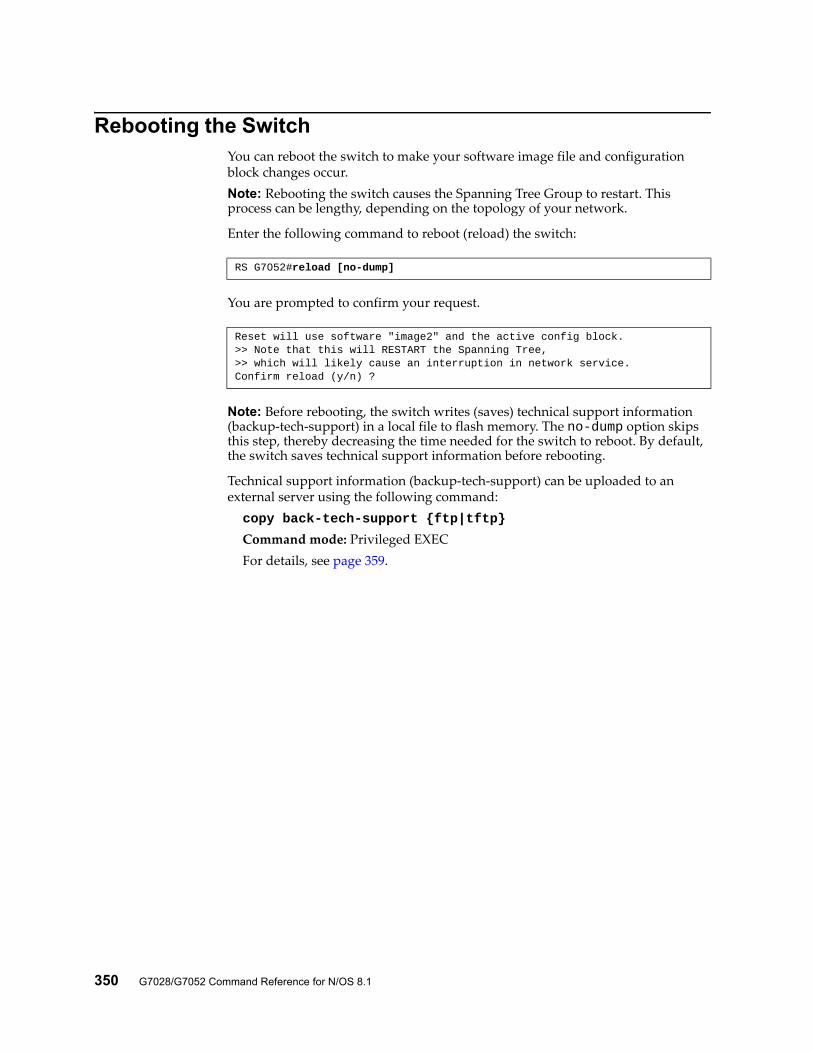
350 G7028/G7052 Command Reference for N/OS 8.1
Rebooting the SwitchYou can reboot the switch to make your software image file and configuration block changes occur.Note: Rebooting the switch causes the Spanning Tree Group to restart. This process can be lengthy, depending on the topology of your network.
Enter the following command to reboot (reload) the switch:
You are prompted to confirm your request.
Note: Before rebooting, the switch writes (saves) technical support information (backup-tech-support) in a local file to flash memory. The no-dump option skips this step, thereby decreasing the time needed for the switch to reboot. By default, the switch saves technical support information before rebooting.
Technical support information (backup-tech-support) can be uploaded to an external server using the following command:copy back-tech-support {ftp|tftp}
Command mode: Privileged EXECFor details, see page 359.
RS G7052#reload [no-dump]
Reset will use software "image2" and the active config block.>> Note that this will RESTART the Spanning Tree,>> which will likely cause an interruption in network service.Confirm reload (y/n) ?
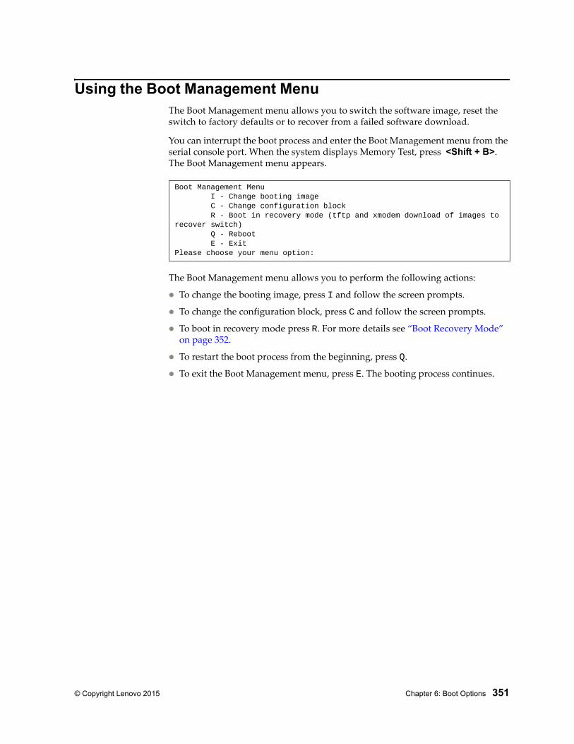
© Copyright Lenovo 2015 Chapter 6: Boot Options 351
Using the Boot Management MenuThe Boot Management menu allows you to switch the software image, reset the switch to factory defaults or to recover from a failed software download.
You can interrupt the boot process and enter the Boot Management menu from the serial console port. When the system displays Memory Test, press <Shift + B>. The Boot Management menu appears.
The Boot Management menu allows you to perform the following actions:
To change the booting image, press I and follow the screen prompts.
To change the configuration block, press C and follow the screen prompts.
To boot in recovery mode press R. For more details see “Boot Recovery Mode” on page 352.
To restart the boot process from the beginning, press Q.
To exit the Boot Management menu, press E. The booting process continues.
Boot Management Menu I - Change booting image C - Change configuration block R - Boot in recovery mode (tftp and xmodem download of images to recover switch) Q - Reboot E - ExitPlease choose your menu option:
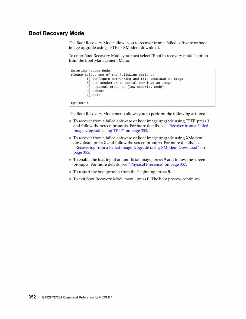
352 G7028/G7052 Command Reference for N/OS 8.1
Boot Recovery Mode
The Boot Recovery Mode allows you to recover from a failed software or boot image upgrade using TFTP or XModem download.
To enter Boot Recovery Mode you must select “Boot in recovery mode” option from the Boot Management Menu.
The Boot Recovery Mode menu allows you to perform the following actions:
To recover from a failed software or boot image upgrade using TFTP, press T and follow the screen prompts. For more details, see “Recover from a Failed Image Upgrade using TFTP” on page 353.
To recover from a failed software or boot image upgrade using XModem download, press X and follow the screen prompts. For more details, see “Recovering from a Failed Image Upgrade using XModem Download” on page 355.
To enable the loading of an unofficial image, press P and follow the screen prompts. For more details, see “Physical Presence” on page 357.
To restart the boot process from the beginning, press R.
To exit Boot Recovery Mode menu, press E. The boot process continues.
Entering Rescue Mode.Please select one of the following options: T) Configure networking and tftp download an image X) Use xmodem 1K to serial download an image P) Physical presence (low security mode) R) Reboot E) Exit
Option? :
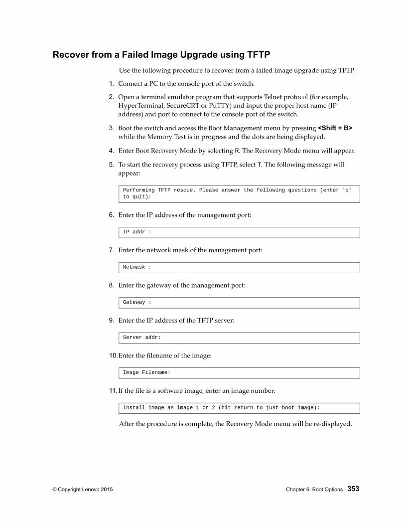
© Copyright Lenovo 2015 Chapter 6: Boot Options 353
Recover from a Failed Image Upgrade using TFTP
Use the following procedure to recover from a failed image upgrade using TFTP:
1. Connect a PC to the console port of the switch.
2. Open a terminal emulator program that supports Telnet protocol (for example, HyperTerminal, SecureCRT or PuTTY) and input the proper host name (IP address) and port to connect to the console port of the switch.
3. Boot the switch and access the Boot Management menu by pressing <Shift + B> while the Memory Test is in progress and the dots are being displayed.
4. Enter Boot Recovery Mode by selecting R. The Recovery Mode menu will appear.
5. To start the recovery process using TFTP, select T. The following message will appear:
6. Enter the IP address of the management port:
7. Enter the network mask of the management port:
8. Enter the gateway of the management port:
9. Enter the IP address of the TFTP server:
10.Enter the filename of the image:
11. If the file is a software image, enter an image number:
After the procedure is complete, the Recovery Mode menu will be re-displayed.
Performing TFTP rescue. Please answer the following questions (enter 'q' to quit):
IP addr :
Netmask :
Gateway :
Server addr:
Image Filename:
Install image as image 1 or 2 (hit return to just boot image):
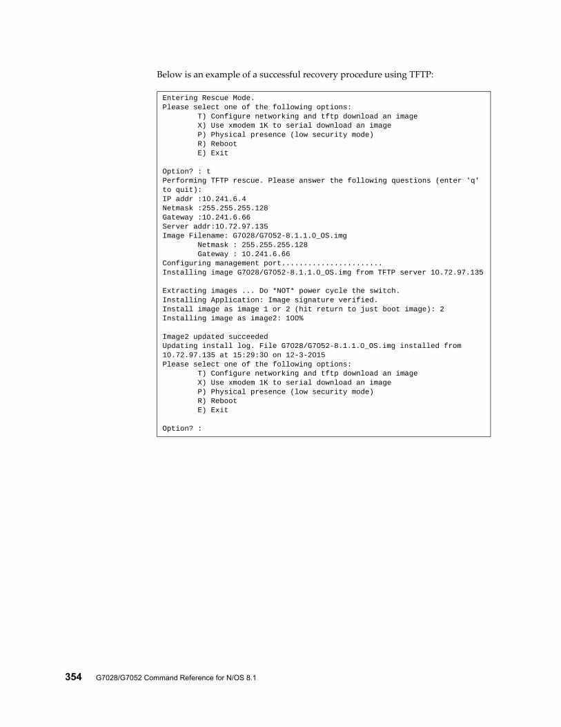
354 G7028/G7052 Command Reference for N/OS 8.1
Below is an example of a successful recovery procedure using TFTP:
Entering Rescue Mode.Please select one of the following options: T) Configure networking and tftp download an image X) Use xmodem 1K to serial download an image P) Physical presence (low security mode) R) Reboot E) Exit
Option? : tPerforming TFTP rescue. Please answer the following questions (enter 'q' to quit):IP addr :10.241.6.4Netmask :255.255.255.128Gateway :10.241.6.66Server addr:10.72.97.135Image Filename: G7028/G7052-8.1.1.0_OS.img Netmask : 255.255.255.128 Gateway : 10.241.6.66Configuring management port.......................Installing image G7028/G7052-8.1.1.0_OS.img from TFTP server 10.72.97.135
Extracting images ... Do *NOT* power cycle the switch.Installing Application: Image signature verified.Install image as image 1 or 2 (hit return to just boot image): 2Installing image as image2: 100%
Image2 updated succeededUpdating install log. File G7028/G7052-8.1.1.0_OS.img installed from 10.72.97.135 at 15:29:30 on 12-3-2015Please select one of the following options: T) Configure networking and tftp download an image X) Use xmodem 1K to serial download an image P) Physical presence (low security mode) R) Reboot E) Exit
Option? :
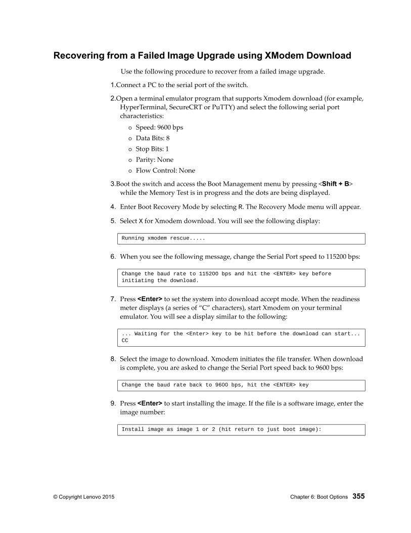
© Copyright Lenovo 2015 Chapter 6: Boot Options 355
Recovering from a Failed Image Upgrade using XModem Download
Use the following procedure to recover from a failed image upgrade.
1.Connect a PC to the serial port of the switch.
2.Open a terminal emulator program that supports Xmodem download (for example, HyperTerminal, SecureCRT or PuTTY) and select the following serial port characteristics:
Speed: 9600 bps Data Bits: 8 Stop Bits: 1 Parity: None Flow Control: None
3.Boot the switch and access the Boot Management menu by pressing <Shift + B> while the Memory Test is in progress and the dots are being displayed.
4. Enter Boot Recovery Mode by selecting R. The Recovery Mode menu will appear.
5. Select X for Xmodem download. You will see the following display:
6. When you see the following message, change the Serial Port speed to 115200 bps:
7. Press <Enter> to set the system into download accept mode. When the readiness meter displays (a series of “C” characters), start Xmodem on your terminal emulator. You will see a display similar to the following:
8. Select the image to download. Xmodem initiates the file transfer. When download is complete, you are asked to change the Serial Port speed back to 9600 bps:
9. Press <Enter> to start installing the image. If the file is a software image, enter the image number:
Running xmodem rescue.....
Change the baud rate to 115200 bps and hit the <ENTER> key before initiating the download.
... Waiting for the <Enter> key to be hit before the download can start...CC
Change the baud rate back to 9600 bps, hit the <ENTER> key
Install image as image 1 or 2 (hit return to just boot image):
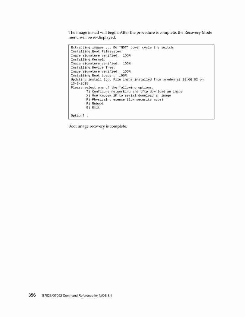
356 G7028/G7052 Command Reference for N/OS 8.1
The image install will begin. After the procedure is complete, the Recovery Mode menu will be re-displayed.
Boot image recovery is complete.
Extracting images ... Do *NOT* power cycle the switch.Installing Root Filesystem:Image signature verified. 100%Installing Kernel:Image signature verified. 100%Installing Device Tree:Image signature verified. 100%Installing Boot Loader: 100%Updating install log. File image installed from xmodem at 18:06:02 on 13-3-2015Please select one of the following options: T) Configure networking and tftp download an image X) Use xmodem 1K to serial download an image P) Physical presence (low security mode) R) Reboot E) Exit
Option? :
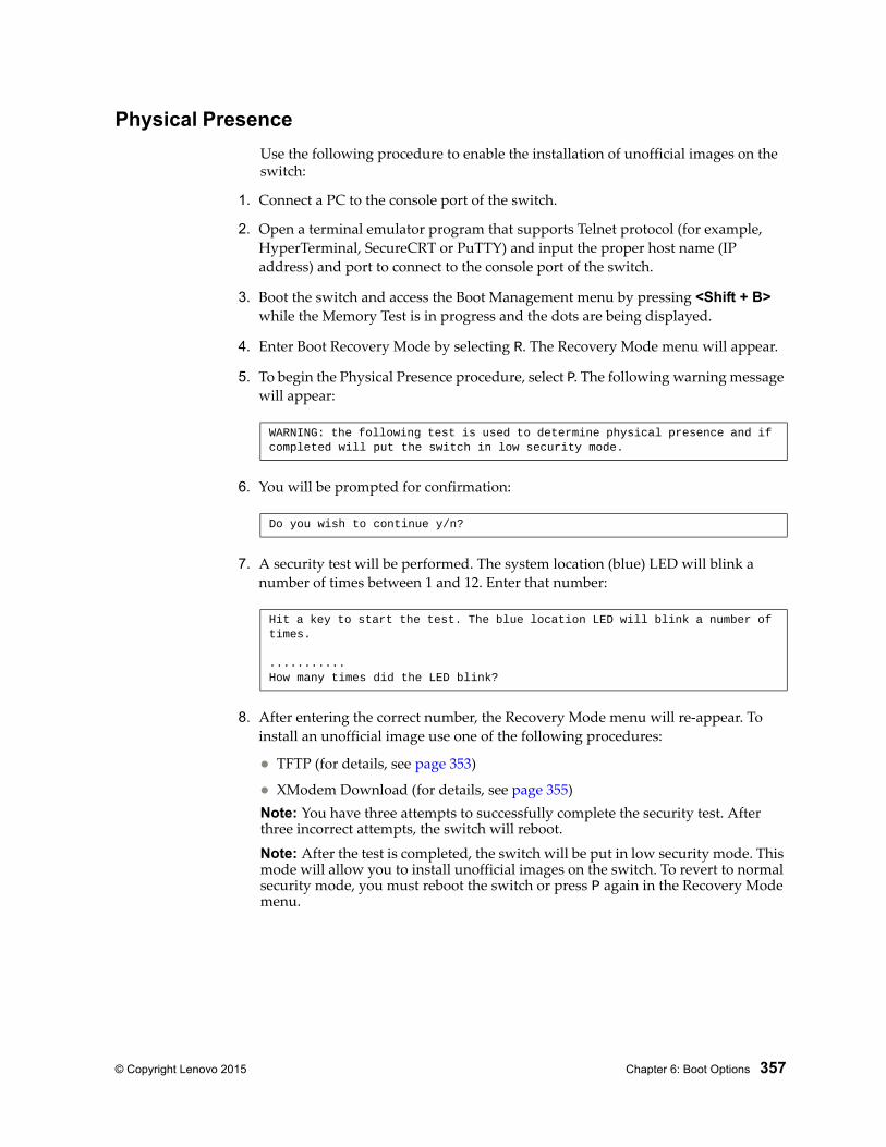
© Copyright Lenovo 2015 Chapter 6: Boot Options 357
Physical Presence
Use the following procedure to enable the installation of unofficial images on the switch:
1. Connect a PC to the console port of the switch.
2. Open a terminal emulator program that supports Telnet protocol (for example, HyperTerminal, SecureCRT or PuTTY) and input the proper host name (IP address) and port to connect to the console port of the switch.
3. Boot the switch and access the Boot Management menu by pressing <Shift + B> while the Memory Test is in progress and the dots are being displayed.
4. Enter Boot Recovery Mode by selecting R. The Recovery Mode menu will appear.
5. To begin the Physical Presence procedure, select P. The following warning message will appear:
6. You will be prompted for confirmation:
7. A security test will be performed. The system location (blue) LED will blink a number of times between 1 and 12. Enter that number:
8. After entering the correct number, the Recovery Mode menu will re-appear. To install an unofficial image use one of the following procedures:
TFTP (for details, see page 353)
XModem Download (for details, see page 355)Note: You have three attempts to successfully complete the security test. After three incorrect attempts, the switch will reboot.
Note: After the test is completed, the switch will be put in low security mode. This mode will allow you to install unofficial images on the switch. To revert to normal security mode, you must reboot the switch or press P again in the Recovery Mode menu.
WARNING: the following test is used to determine physical presence and if completed will put the switch in low security mode.
Do you wish to continue y/n?
Hit a key to start the test. The blue location LED will blink a number of times.
...........How many times did the LED blink?

358 G7028/G7052 Command Reference for N/OS 8.1
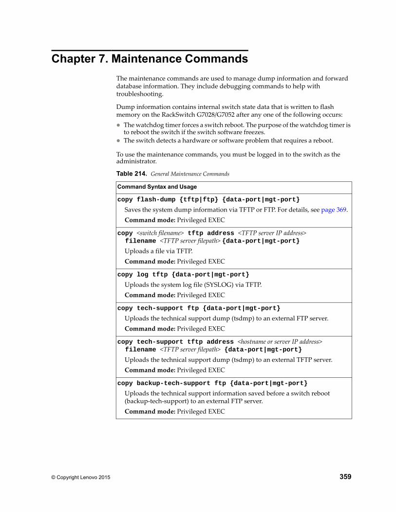
© Copyright Lenovo 2015 359
Chapter 7. Maintenance Commands
The maintenance commands are used to manage dump information and forward database information. They include debugging commands to help with troubleshooting.
Dump information contains internal switch state data that is written to flash memory on the RackSwitch G7028/G7052 after any one of the following occurs: The watchdog timer forces a switch reboot. The purpose of the watchdog timer is
to reboot the switch if the switch software freezes. The switch detects a hardware or software problem that requires a reboot.
To use the maintenance commands, you must be logged in to the switch as the administrator.
Table 214. General Maintenance Commands
Command Syntax and Usage
copy flash-dump {tftp|ftp} {data-port|mgt-port}
Saves the system dump information via TFTP or FTP. For details, see page 369.Command mode: Privileged EXEC
copy <switch filename> tftp address <TFTP server IP address> filename <TFTP server filepath> {data-port|mgt-port}
Uploads a file via TFTP.Command mode: Privileged EXEC
copy log tftp {data-port|mgt-port}
Uploads the system log file (SYSLOG) via TFTP.Command mode: Privileged EXEC
copy tech-support ftp {data-port|mgt-port}
Uploads the technical support dump (tsdmp) to an external FTP server.Command mode: Privileged EXEC
copy tech-support tftp address <hostname or server IP address> filename <TFTP server filepath> {data-port|mgt-port}
Uploads the technical support dump (tsdmp) to an external TFTP server.Command mode: Privileged EXEC
copy backup-tech-support ftp {data-port|mgt-port}
Uploads the technical support information saved before a switch reboot (backup-tech-support) to an external FTP server.Command mode: Privileged EXEC
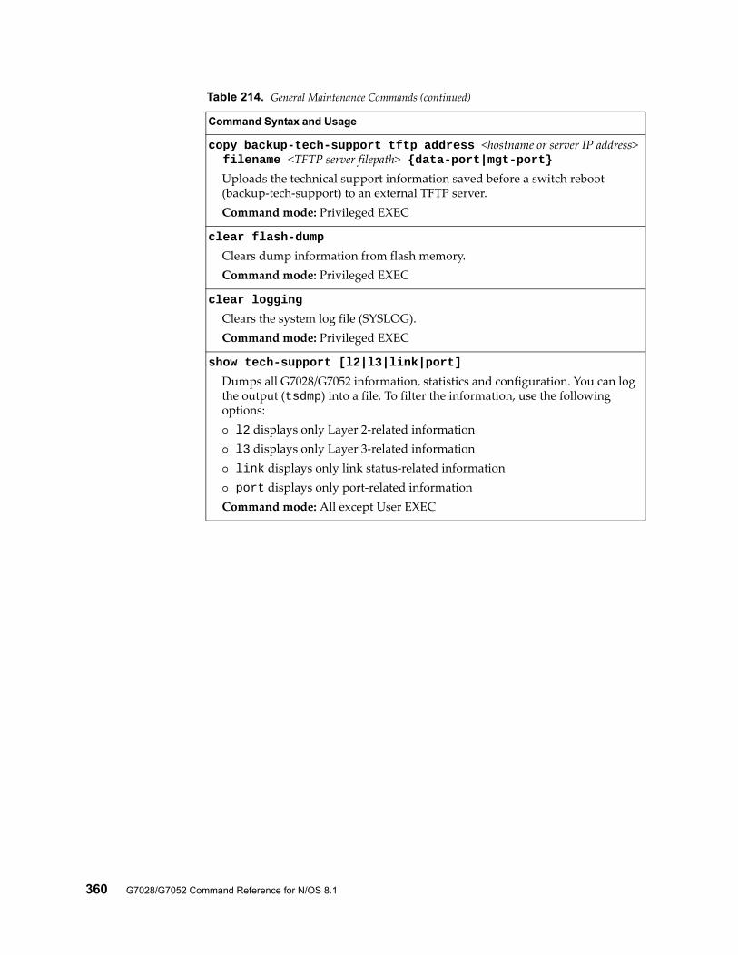
360 G7028/G7052 Command Reference for N/OS 8.1
copy backup-tech-support tftp address <hostname or server IP address> filename <TFTP server filepath> {data-port|mgt-port}
Uploads the technical support information saved before a switch reboot (backup-tech-support) to an external TFTP server.Command mode: Privileged EXEC
clear flash-dump
Clears dump information from flash memory.Command mode: Privileged EXEC
clear logging
Clears the system log file (SYSLOG).Command mode: Privileged EXEC
show tech-support [l2|l3|link|port]
Dumps all G7028/G7052 information, statistics and configuration. You can log the output (tsdmp) into a file. To filter the information, use the following options: l2 displays only Layer 2-related information l3 displays only Layer 3-related information link displays only link status-related information port displays only port-related informationCommand mode: All except User EXEC
Table 214. General Maintenance Commands (continued)
Command Syntax and Usage
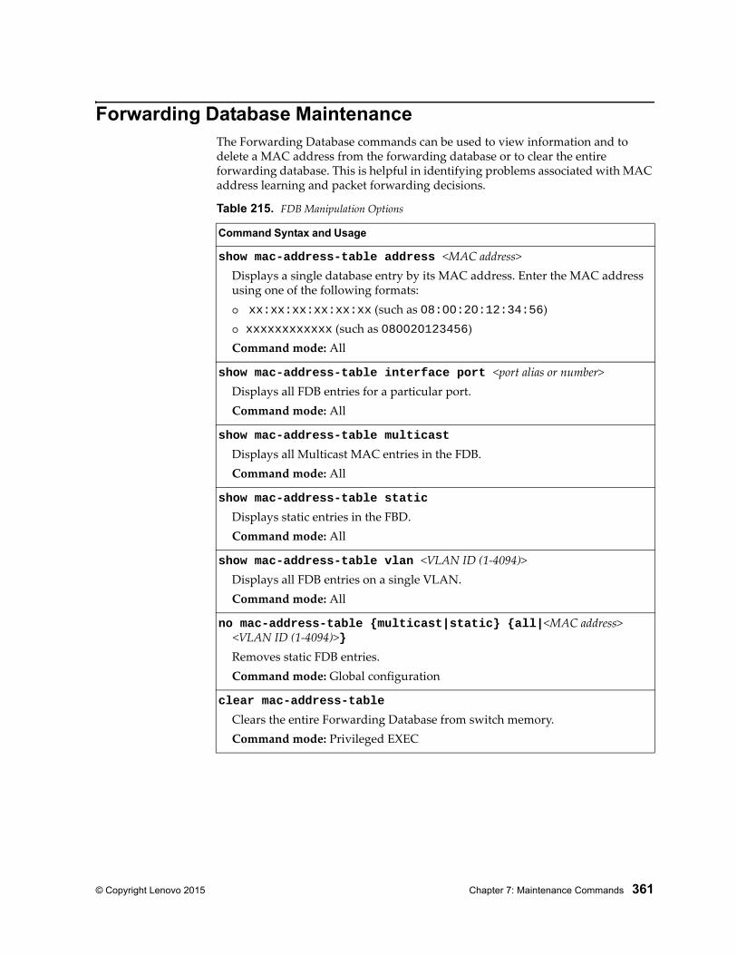
© Copyright Lenovo 2015 Chapter 7: Maintenance Commands 361
Forwarding Database MaintenanceThe Forwarding Database commands can be used to view information and to delete a MAC address from the forwarding database or to clear the entire forwarding database. This is helpful in identifying problems associated with MAC address learning and packet forwarding decisions.
Table 215. FDB Manipulation Options
Command Syntax and Usage
show mac-address-table address <MAC address>Displays a single database entry by its MAC address. Enter the MAC address using one of the following formats: xx:xx:xx:xx:xx:xx (such as 08:00:20:12:34:56) xxxxxxxxxxxx (such as 080020123456)Command mode: All
show mac-address-table interface port <port alias or number>Displays all FDB entries for a particular port.Command mode: All
show mac-address-table multicast
Displays all Multicast MAC entries in the FDB.Command mode: All
show mac-address-table static
Displays static entries in the FBD.Command mode: All
show mac-address-table vlan <VLAN ID (1-4094)>Displays all FDB entries on a single VLAN.Command mode: All
no mac-address-table {multicast|static} {all|<MAC address> <VLAN ID (1-4094)>}
Removes static FDB entries.Command mode: Global configuration
clear mac-address-table
Clears the entire Forwarding Database from switch memory.Command mode: Privileged EXEC
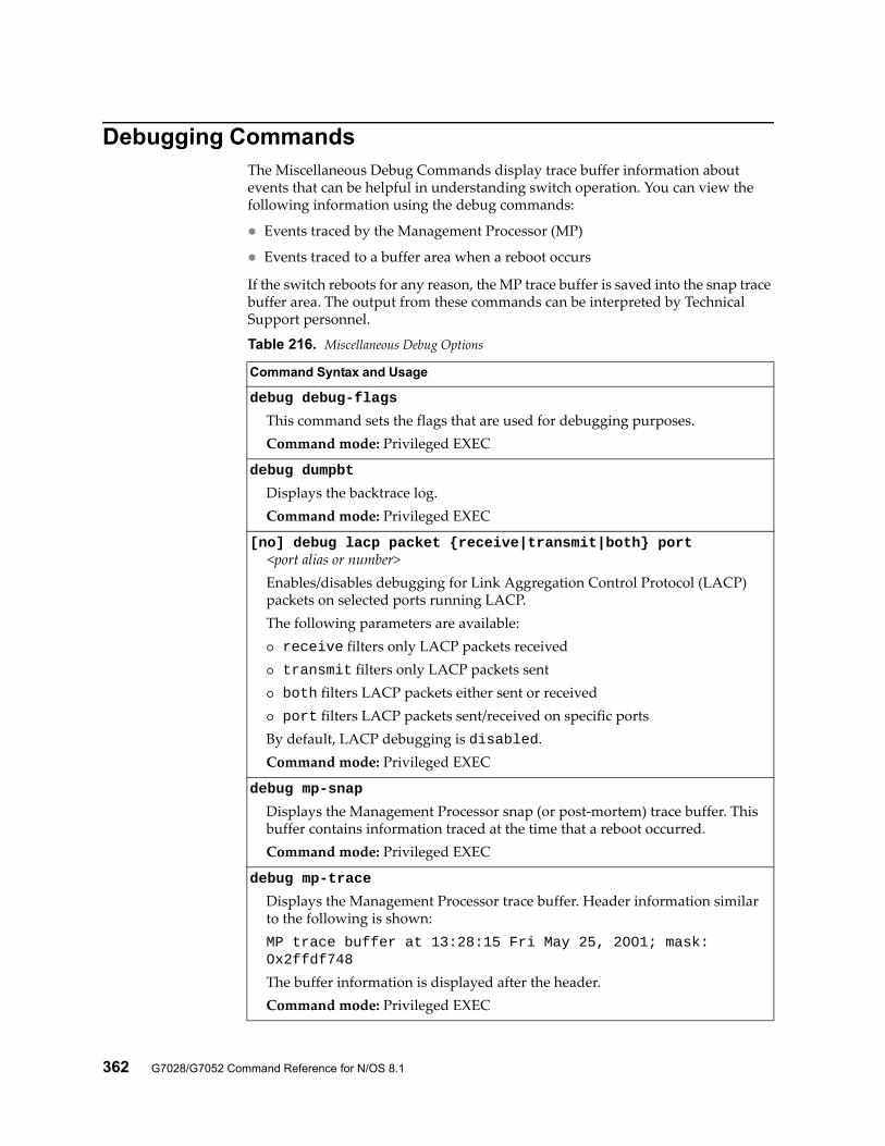
362 G7028/G7052 Command Reference for N/OS 8.1
Debugging CommandsThe Miscellaneous Debug Commands display trace buffer information about events that can be helpful in understanding switch operation. You can view the following information using the debug commands:
Events traced by the Management Processor (MP)
Events traced to a buffer area when a reboot occurs
If the switch reboots for any reason, the MP trace buffer is saved into the snap trace buffer area. The output from these commands can be interpreted by Technical Support personnel.
Table 216. Miscellaneous Debug Options
Command Syntax and Usage
debug debug-flags
This command sets the flags that are used for debugging purposes.Command mode: Privileged EXEC
debug dumpbt
Displays the backtrace log.Command mode: Privileged EXEC
[no] debug lacp packet {receive|transmit|both} port <port alias or number>
Enables/disables debugging for Link Aggregation Control Protocol (LACP) packets on selected ports running LACP.The following parameters are available: receive filters only LACP packets received transmit filters only LACP packets sent both filters LACP packets either sent or received port filters LACP packets sent/received on specific portsBy default, LACP debugging is disabled.Command mode: Privileged EXEC
debug mp-snap
Displays the Management Processor snap (or post-mortem) trace buffer. This buffer contains information traced at the time that a reboot occurred.Command mode: Privileged EXEC
debug mp-trace
Displays the Management Processor trace buffer. Header information similar to the following is shown:MP trace buffer at 13:28:15 Fri May 25, 2001; mask: 0x2ffdf748
The buffer information is displayed after the header.Command mode: Privileged EXEC
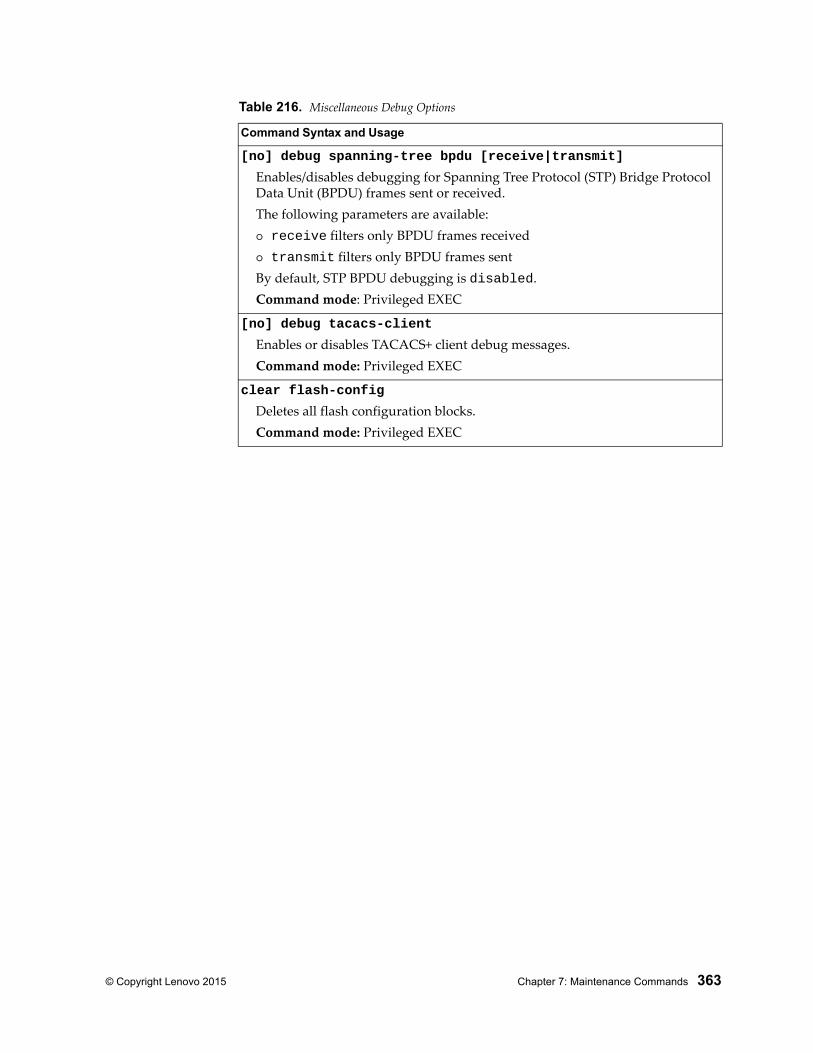
© Copyright Lenovo 2015 Chapter 7: Maintenance Commands 363
[no] debug spanning-tree bpdu [receive|transmit]
Enables/disables debugging for Spanning Tree Protocol (STP) Bridge Protocol Data Unit (BPDU) frames sent or received.The following parameters are available: receive filters only BPDU frames received transmit filters only BPDU frames sentBy default, STP BPDU debugging is disabled.Command mode: Privileged EXEC
[no] debug tacacs-client
Enables or disables TACACS+ client debug messages.Command mode: Privileged EXEC
clear flash-config
Deletes all flash configuration blocks.Command mode: Privileged EXEC
Table 216. Miscellaneous Debug Options
Command Syntax and Usage

364 G7028/G7052 Command Reference for N/OS 8.1
SSH DebuggingThe following table describes the SSH debugging commands.
Table 217. SSH Debugging Options
Command Syntax and Usage
[no] debug ssh server all
Enables or disables all SSH Server debug messages.Command mode: Privileged EXEC
[no] debug ssh server disconnect
Enables or disables SSH Server disconnect debug messages.Command mode: Privileged EXEC
[no] debug ssh server msg
Enables or disables SSH Server type and protocol debug messages.Command mode: Privileged EXEC
[no] debug ssh server packet
Enables or disables SSH Server type, protocol and packet debug messages.Command mode: Privileged EXEC
[no] debug ssh server state
Enables or disables SSH Server state debug messages.Command mode: Privileged EXEC
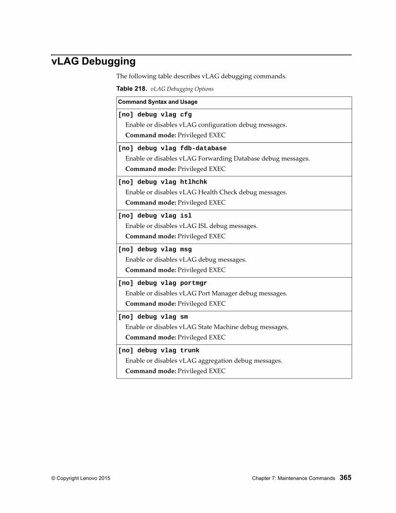
© Copyright Lenovo 2015 Chapter 7: Maintenance Commands 365
vLAG DebuggingThe following table describes vLAG debugging commands.
Table 218. vLAG Debugging Options
Command Syntax and Usage
[no] debug vlag cfg
Enable or disables vLAG configuration debug messages.Command mode: Privileged EXEC
[no] debug vlag fdb-database
Enable or disables vLAG Forwarding Database debug messages.Command mode: Privileged EXEC
[no] debug vlag htlhchk
Enable or disables vLAG Health Check debug messages.Command mode: Privileged EXEC
[no] debug vlag isl
Enable or disables vLAG ISL debug messages.Command mode: Privileged EXEC
[no] debug vlag msg
Enable or disables vLAG debug messages.Command mode: Privileged EXEC
[no] debug vlag portmgr
Enable or disables vLAG Port Manager debug messages.Command mode: Privileged EXEC
[no] debug vlag sm
Enable or disables vLAG State Machine debug messages.Command mode: Privileged EXEC
[no] debug vlag trunk
Enable or disables vLAG aggregation debug messages.Command mode: Privileged EXEC
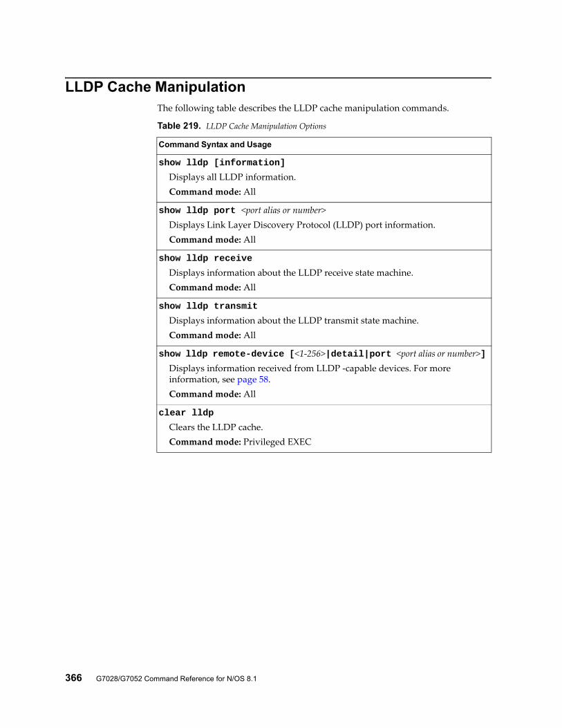
366 G7028/G7052 Command Reference for N/OS 8.1
LLDP Cache ManipulationThe following table describes the LLDP cache manipulation commands.
Table 219. LLDP Cache Manipulation Options
Command Syntax and Usage
show lldp [information]
Displays all LLDP information.Command mode: All
show lldp port <port alias or number>Displays Link Layer Discovery Protocol (LLDP) port information.Command mode: All
show lldp receive
Displays information about the LLDP receive state machine.Command mode: All
show lldp transmit
Displays information about the LLDP transmit state machine.Command mode: All
show lldp remote-device [<1-256>|detail|port <port alias or number>]Displays information received from LLDP -capable devices. For more information, see page 58.Command mode: All
clear lldp
Clears the LLDP cache.Command mode: Privileged EXEC
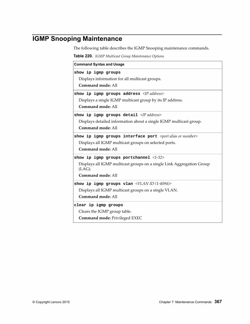
© Copyright Lenovo 2015 Chapter 7: Maintenance Commands 367
IGMP Snooping MaintenanceThe following table describes the IGMP Snooping maintenance commands.
Table 220. IGMP Multicast Group Maintenance Options
Command Syntax and Usage
show ip igmp groups
Displays information for all multicast groups.Command mode: All
show ip igmp groups address <IP address>Displays a single IGMP multicast group by its IP address.Command mode: All
show ip igmp groups detail <IP address>Displays detailed information about a single IGMP multicast group.Command mode: All
show ip igmp groups interface port <port alias or number>Displays all IGMP multicast groups on selected ports.Command mode: All
show ip igmp groups portchannel <1-32>Displays all IGMP multicast groups on a single Link Aggregation Group (LAG).Command mode: All
show ip igmp groups vlan <VLAN ID (1-4094)>Displays all IGMP multicast groups on a single VLAN.Command mode: All
clear ip igmp groups
Clears the IGMP group table.Command mode: Privileged EXEC
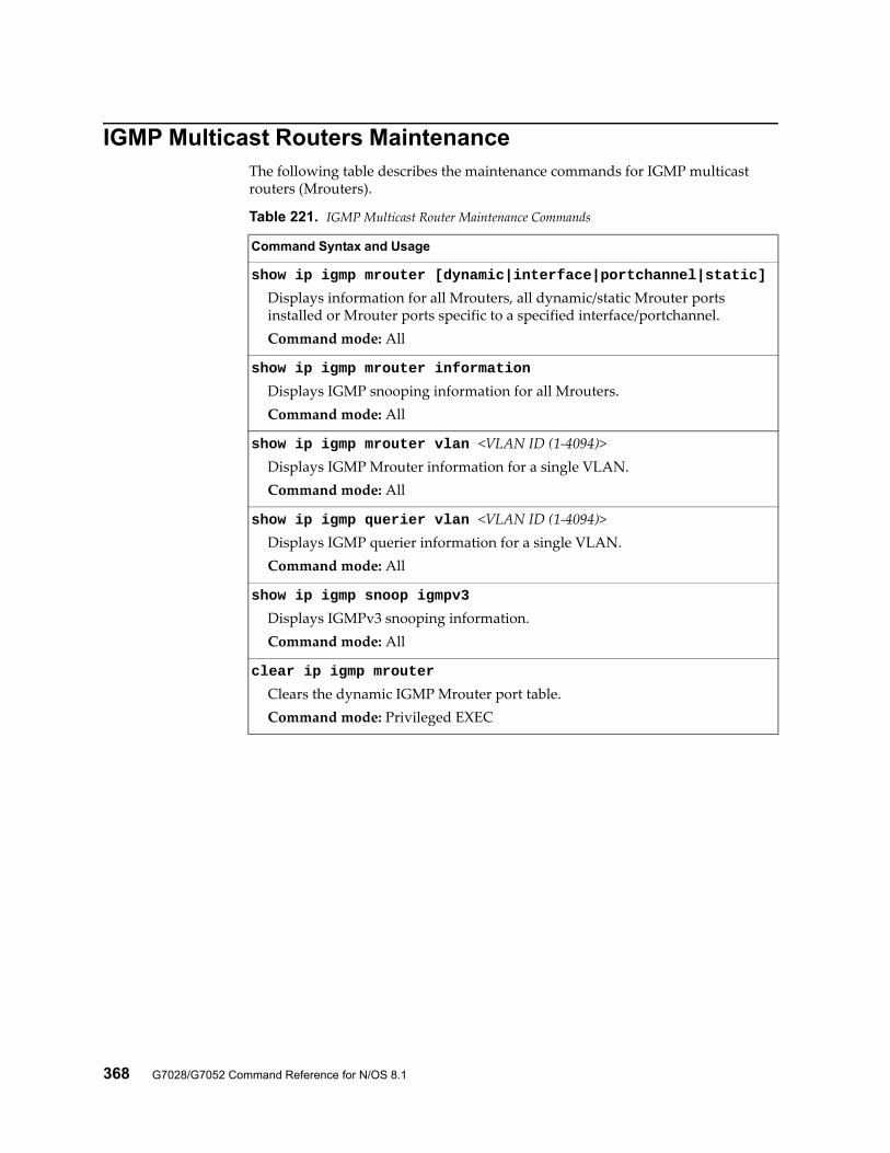
368 G7028/G7052 Command Reference for N/OS 8.1
IGMP Multicast Routers MaintenanceThe following table describes the maintenance commands for IGMP multicast routers (Mrouters).
Table 221. IGMP Multicast Router Maintenance Commands
Command Syntax and Usage
show ip igmp mrouter [dynamic|interface|portchannel|static]
Displays information for all Mrouters, all dynamic/static Mrouter ports installed or Mrouter ports specific to a specified interface/portchannel.Command mode: All
show ip igmp mrouter information
Displays IGMP snooping information for all Mrouters.Command mode: All
show ip igmp mrouter vlan <VLAN ID (1-4094)>Displays IGMP Mrouter information for a single VLAN.Command mode: All
show ip igmp querier vlan <VLAN ID (1-4094)>Displays IGMP querier information for a single VLAN.Command mode: All
show ip igmp snoop igmpv3
Displays IGMPv3 snooping information.Command mode: All
clear ip igmp mrouter
Clears the dynamic IGMP Mrouter port table.Command mode: Privileged EXEC
© Copyright Lenovo 2015 Chapter 7: Maintenance Commands 369
TFTP or FTP System Dump CopyUse these commands to copy (save) the system dump to a TFTP or FTP server.Note: If the TFTP/FTP server is running SunOS or the Solaris operating system, the specified file must exist prior to executing the copy flash-dump tftp command and must be writable (set with proper permission and not locked by any application). The contents of the specified file will be replaced with the current dump data.
To save dump information via TFTP, enter:
You are prompted for the TFTP server IP address or hostname, and the filename of the target dump file.
To save dump information via FTP, enter:
You are prompted for the FTP server IPv4 address or hostname, your username and password, and the filename of the target dump file.
RS G7052#copy flash-dump tftp <server filename>
RS G7052#copy flash-dump ftp <server filename>
370 G7028/G7052 Command Reference for N/OS 8.1
Clearing Dump InformationTo clear dump information from flash memory, enter:
The switch clears the dump region of flash memory and displays the following message:
If the flash dump region is already clear, the switch displays the following message:
RS G7052#clear flash-dump
FLASH dump region cleared.
FLASH dump region is already clear.
© Copyright Lenovo 2015 Chapter 7: Maintenance Commands 371
Unscheduled System DumpsIf there is an unscheduled system dump to flash memory, the following message is displayed when you log on to the switch:
Note: A system dump exists in FLASH. The dump was savedat 13:43:22 Wednesday January 30, 2011. Use show flash-dumpuuencode toextract the dump for analysis and clear flash-dump toclear the FLASH region. The region must be clearedbefore another dump can be saved.

372 G7028/G7052 Command Reference for N/OS 8.1
© Copyright Lenovo 2015 373
Appendix A. Lenovo N/OS System Log Messages
The RackSwitch G7028/G7052 uses the following syntax when outputting system log (syslog) messages:
<Time stamp> <IP/Hostname> <Log Label> <Thread ID>:<Message>
The following parameters are used:
<Timestamp>The time of the message event is displayed in the following format:<month (3 characters)> <day> <hour (1-24)>:<minute>:<second>For example: Aug 19 14:20:30
<IP/Hostname>The hostname is displayed when configured.For example: 1.1.1.1
<Log Label>The following types of log messages are recorded: LOG_CRIT, LOG_WARNING, LOG_ALERT, LOG_ERR, LOG_NOTICE and LOG_INFO.
<Thread ID>This is the software thread that reports the log message.For example:stg, ip, console, telnet, system, web server, ssh
<Message>: The log message
Following is a list of potential syslog messages. To keep this list as short as possible, only the <Thread ID> and <Message> are shown. The messages are sorted by <Log Label>.
Where the <Thread ID> is listed as mgmt, one of the following may be shown: console, telnet, web server or ssh.
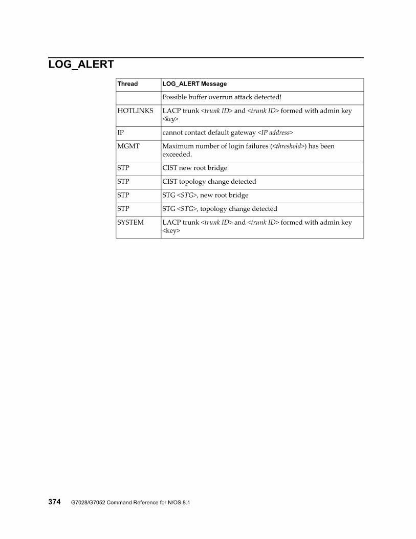
374 G7028/G7052 Command Reference for N/OS 8.1
LOG_ALERT
Thread LOG_ALERT Message
Possible buffer overrun attack detected!
HOTLINKS LACP trunk <trunk ID> and <trunk ID> formed with admin key <key>
IP cannot contact default gateway <IP address>
MGMT Maximum number of login failures (<threshold>) has been exceeded.
STP CIST new root bridge
STP CIST topology change detected
STP STG <STG>, new root bridge
STP STG <STG>, topology change detected
SYSTEM LACP trunk <trunk ID> and <trunk ID> formed with admin key <key>

© Copyright Lenovo 2015 Appendix A: Lenovo N/OS System Log Messages 375
LOG_CRIT
Thread LOG_CRIT Message
SSH can't allocate memory in load_MP_INT()
SSH currently not enough resource for loading RSA {private|public key}
SYSTEM System memory is at <n> percent
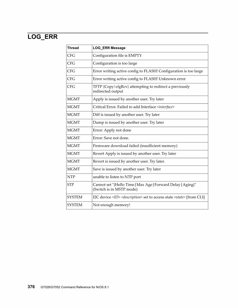
376 G7028/G7052 Command Reference for N/OS 8.1
LOG_ERR
Thread LOG_ERR Message
CFG Configuration file is EMPTY
CFG Configuration is too large
CFG Error writing active config to FLASH! Configuration is too large
CFG Error writing active config to FLASH! Unknown error
CFG TFTP {Copy|cfgRcv} attempting to redirect a previously redirected output
MGMT Apply is issued by another user. Try later
MGMT Critical Error. Failed to add Interface <interface>
MGMT Diff is issued by another user. Try later
MGMT Dump is issued by another user. Try later
MGMT Error: Apply not done
MGMT Error: Save not done.
MGMT Firmware download failed (insufficient memory)
MGMT Revert Apply is issued by another user. Try later
MGMT Revert is issued by another user. Try later.
MGMT Save is issued by another user. Try later
NTP unable to listen to NTP port
STP Cannot set "{Hello Time|Max Age|Forward Delay|Aging}" (Switch is in MSTP mode)
SYSTEM I2C device <ID> <description> set to access state <state> [from CLI]
SYSTEM Not enough memory!
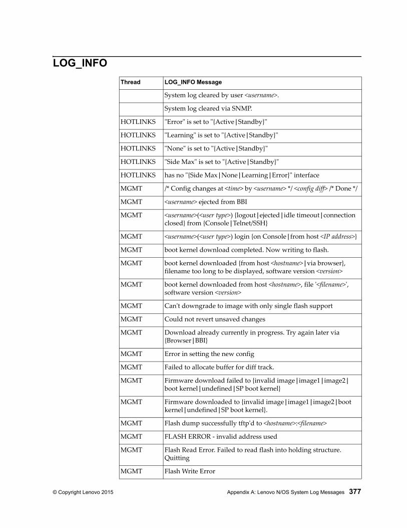
© Copyright Lenovo 2015 Appendix A: Lenovo N/OS System Log Messages 377
LOG_INFO
Thread LOG_INFO Message
System log cleared by user <username>.
System log cleared via SNMP.
HOTLINKS "Error" is set to "{Active|Standby}"
HOTLINKS "Learning" is set to "{Active|Standby}"
HOTLINKS "None" is set to "{Active|Standby}"
HOTLINKS "Side Max" is set to "{Active|Standby}"
HOTLINKS has no "{Side Max|None|Learning|Error}" interface
MGMT /* Config changes at <time> by <username> */ <config diff> /* Done */
MGMT <username> ejected from BBI
MGMT <username>(<user type>) {logout|ejected|idle timeout|connection closed} from {Console|Telnet/SSH}
MGMT <username>(<user type>) login {on Console|from host <IP address>}
MGMT boot kernel download completed. Now writing to flash.
MGMT boot kernel downloaded {from host <hostname>|via browser}, filename too long to be displayed, software version <version>
MGMT boot kernel downloaded from host <hostname>, file '<filename>', software version <version>
MGMT Can't downgrade to image with only single flash support
MGMT Could not revert unsaved changes
MGMT Download already currently in progress. Try again later via {Browser|BBI}
MGMT Error in setting the new config
MGMT Failed to allocate buffer for diff track.
MGMT Firmware download failed to {invalid image|image1|image2|boot kernel|undefined|SP boot kernel}
MGMT Firmware downloaded to {invalid image|image1|image2|boot kernel|undefined|SP boot kernel}.
MGMT Flash dump successfully tftp'd to <hostname>:<filename>
MGMT FLASH ERROR - invalid address used
MGMT Flash Read Error. Failed to read flash into holding structure. Quitting
MGMT Flash Write Error
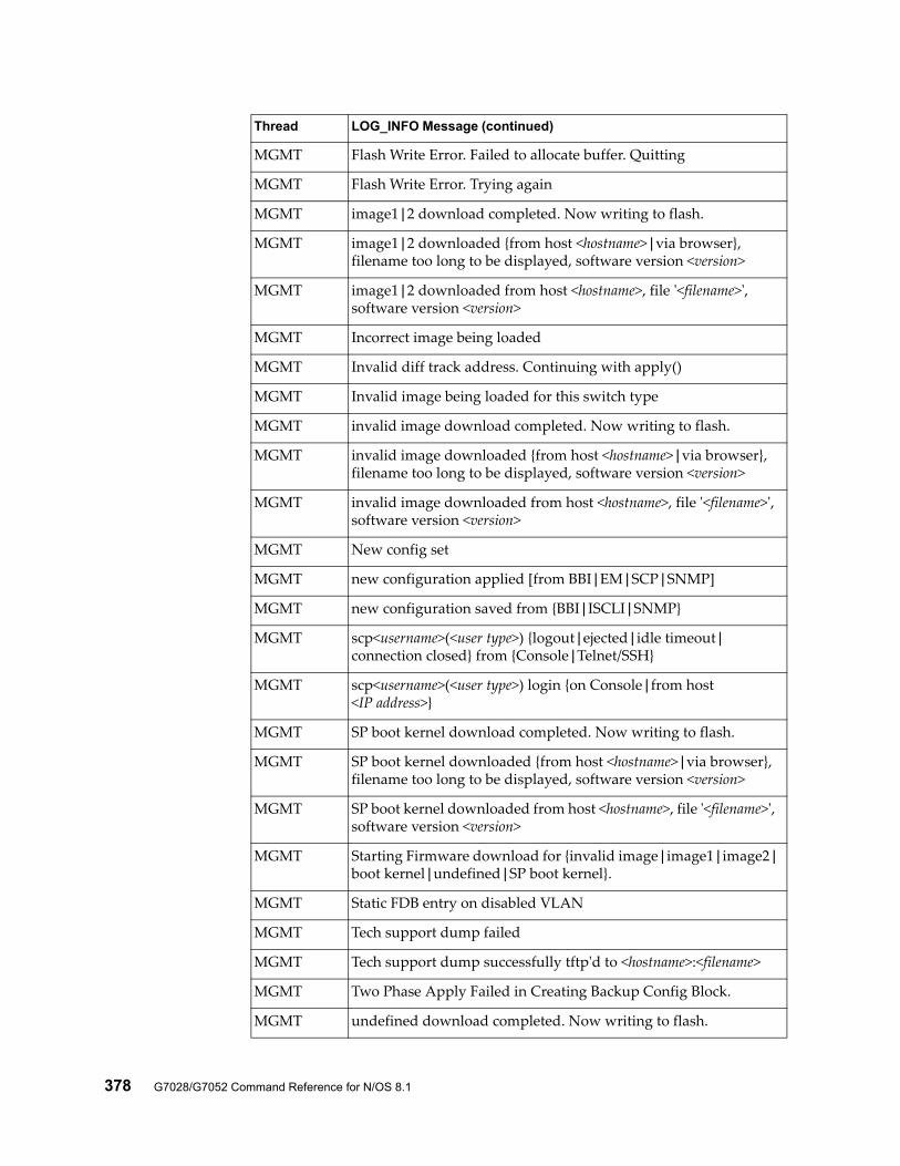
378 G7028/G7052 Command Reference for N/OS 8.1
MGMT Flash Write Error. Failed to allocate buffer. Quitting
MGMT Flash Write Error. Trying again
MGMT image1|2 download completed. Now writing to flash.
MGMT image1|2 downloaded {from host <hostname>|via browser}, filename too long to be displayed, software version <version>
MGMT image1|2 downloaded from host <hostname>, file '<filename>', software version <version>
MGMT Incorrect image being loaded
MGMT Invalid diff track address. Continuing with apply()
MGMT Invalid image being loaded for this switch type
MGMT invalid image download completed. Now writing to flash.
MGMT invalid image downloaded {from host <hostname>|via browser}, filename too long to be displayed, software version <version>
MGMT invalid image downloaded from host <hostname>, file '<filename>', software version <version>
MGMT New config set
MGMT new configuration applied [from BBI|EM|SCP|SNMP]
MGMT new configuration saved from {BBI|ISCLI|SNMP}
MGMT scp<username>(<user type>) {logout|ejected|idle timeout|connection closed} from {Console|Telnet/SSH}
MGMT scp<username>(<user type>) login {on Console|from host <IP address>}
MGMT SP boot kernel download completed. Now writing to flash.
MGMT SP boot kernel downloaded {from host <hostname>|via browser}, filename too long to be displayed, software version <version>
MGMT SP boot kernel downloaded from host <hostname>, file '<filename>', software version <version>
MGMT Starting Firmware download for {invalid image|image1|image2|boot kernel|undefined|SP boot kernel}.
MGMT Static FDB entry on disabled VLAN
MGMT Tech support dump failed
MGMT Tech support dump successfully tftp'd to <hostname>:<filename>
MGMT Two Phase Apply Failed in Creating Backup Config Block.
MGMT undefined download completed. Now writing to flash.
Thread LOG_INFO Message (continued)
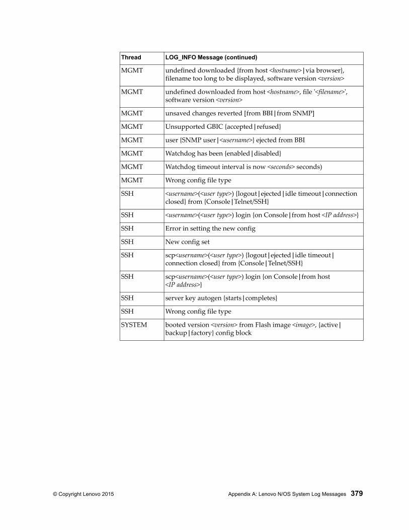
© Copyright Lenovo 2015 Appendix A: Lenovo N/OS System Log Messages 379
MGMT undefined downloaded {from host <hostname>|via browser}, filename too long to be displayed, software version <version>
MGMT undefined downloaded from host <hostname>, file '<filename>', software version <version>
MGMT unsaved changes reverted [from BBI|from SNMP]
MGMT Unsupported GBIC {accepted|refused}
MGMT user {SNMP user|<username>} ejected from BBI
MGMT Watchdog has been {enabled|disabled}
MGMT Watchdog timeout interval is now <seconds> seconds)
MGMT Wrong config file type
SSH <username>(<user type>) {logout|ejected|idle timeout|connection closed} from {Console|Telnet/SSH}
SSH <username>(<user type>) login {on Console|from host <IP address>}
SSH Error in setting the new config
SSH New config set
SSH scp<username>(<user type>) {logout|ejected|idle timeout|connection closed} from {Console|Telnet/SSH}
SSH scp<username>(<user type>) login {on Console|from host <IP address>}
SSH server key autogen {starts|completes}
SSH Wrong config file type
SYSTEM booted version <version> from Flash image <image>, {active|backup|factory} config block
Thread LOG_INFO Message (continued)
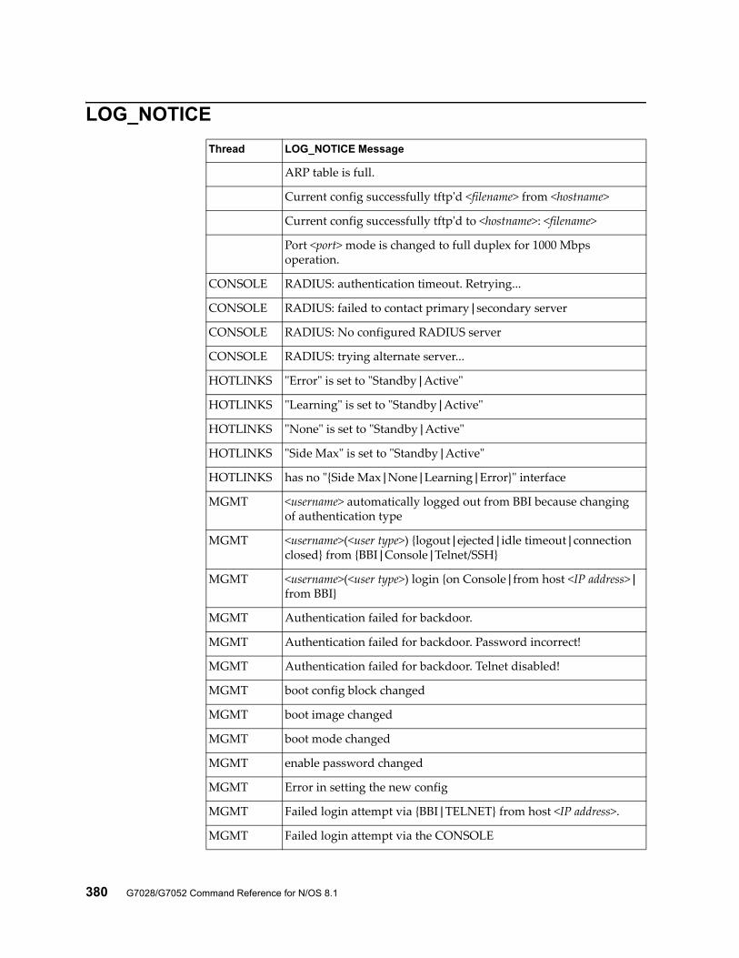
380 G7028/G7052 Command Reference for N/OS 8.1
LOG_NOTICE
Thread LOG_NOTICE Message
ARP table is full.
Current config successfully tftp'd <filename> from <hostname>
Current config successfully tftp'd to <hostname>: <filename>
Port <port> mode is changed to full duplex for 1000 Mbps operation.
CONSOLE RADIUS: authentication timeout. Retrying...
CONSOLE RADIUS: failed to contact primary|secondary server
CONSOLE RADIUS: No configured RADIUS server
CONSOLE RADIUS: trying alternate server...
HOTLINKS "Error" is set to "Standby|Active"
HOTLINKS "Learning" is set to "Standby|Active"
HOTLINKS "None" is set to "Standby|Active"
HOTLINKS "Side Max" is set to "Standby|Active"
HOTLINKS has no "{Side Max|None|Learning|Error}" interface
MGMT <username> automatically logged out from BBI because changing of authentication type
MGMT <username>(<user type>) {logout|ejected|idle timeout|connection closed} from {BBI|Console|Telnet/SSH}
MGMT <username>(<user type>) login {on Console|from host <IP address>|from BBI}
MGMT Authentication failed for backdoor.
MGMT Authentication failed for backdoor. Password incorrect!
MGMT Authentication failed for backdoor. Telnet disabled!
MGMT boot config block changed
MGMT boot image changed
MGMT boot mode changed
MGMT enable password changed
MGMT Error in setting the new config
MGMT Failed login attempt via {BBI|TELNET} from host <IP address>.
MGMT Failed login attempt via the CONSOLE
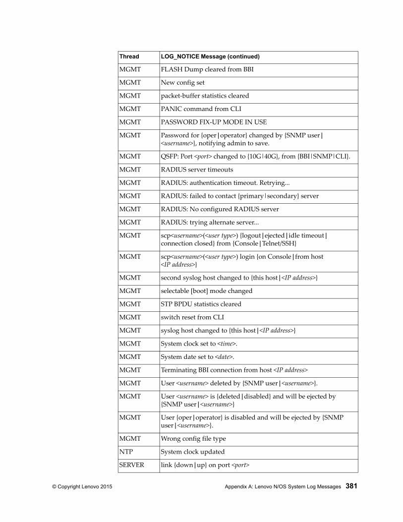
© Copyright Lenovo 2015 Appendix A: Lenovo N/OS System Log Messages 381
MGMT FLASH Dump cleared from BBI
MGMT New config set
MGMT packet-buffer statistics cleared
MGMT PANIC command from CLI
MGMT PASSWORD FIX-UP MODE IN USE
MGMT Password for {oper|operator} changed by {SNMP user|<username>}, notifying admin to save.
MGMT QSFP: Port <port> changed to {10G|40G}, from {BBI|SNMP|CLI}.
MGMT RADIUS server timeouts
MGMT RADIUS: authentication timeout. Retrying...
MGMT RADIUS: failed to contact {primary|secondary} server
MGMT RADIUS: No configured RADIUS server
MGMT RADIUS: trying alternate server...
MGMT scp<username>(<user type>) {logout|ejected|idle timeout|connection closed} from {Console|Telnet/SSH}
MGMT scp<username>(<user type>) login {on Console|from host <IP address>}
MGMT second syslog host changed to {this host|<IP address>}
MGMT selectable [boot] mode changed
MGMT STP BPDU statistics cleared
MGMT switch reset from CLI
MGMT syslog host changed to {this host|<IP address>}
MGMT System clock set to <time>.
MGMT System date set to <date>.
MGMT Terminating BBI connection from host <IP address>
MGMT User <username> deleted by {SNMP user|<username>}.
MGMT User <username> is {deleted|disabled} and will be ejected by {SNMP user|<username>}
MGMT User {oper|operator} is disabled and will be ejected by {SNMP user|<username>}.
MGMT Wrong config file type
NTP System clock updated
SERVER link {down|up} on port <port>
Thread LOG_NOTICE Message (continued)
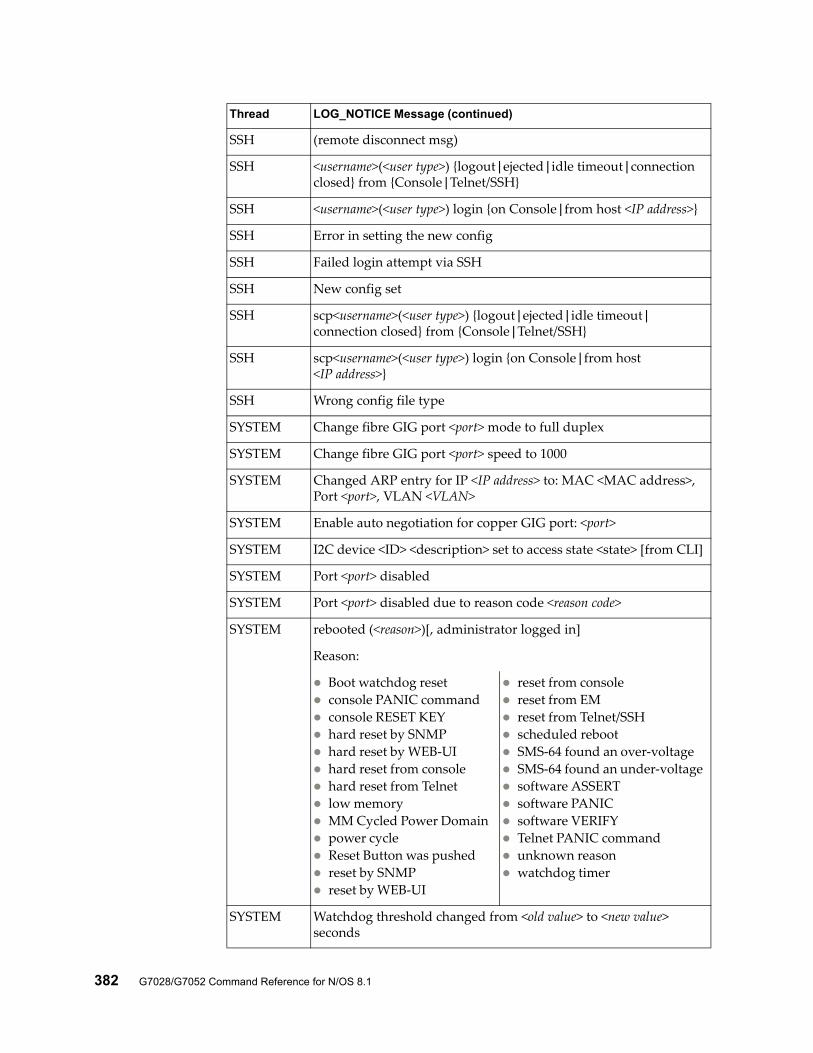
382 G7028/G7052 Command Reference for N/OS 8.1
SSH (remote disconnect msg)
SSH <username>(<user type>) {logout|ejected|idle timeout|connection closed} from {Console|Telnet/SSH}
SSH <username>(<user type>) login {on Console|from host <IP address>}
SSH Error in setting the new config
SSH Failed login attempt via SSH
SSH New config set
SSH scp<username>(<user type>) {logout|ejected|idle timeout|connection closed} from {Console|Telnet/SSH}
SSH scp<username>(<user type>) login {on Console|from host <IP address>}
SSH Wrong config file type
SYSTEM Change fibre GIG port <port> mode to full duplex
SYSTEM Change fibre GIG port <port> speed to 1000
SYSTEM Changed ARP entry for IP <IP address> to: MAC <MAC address>, Port <port>, VLAN <VLAN>
SYSTEM Enable auto negotiation for copper GIG port: <port>
SYSTEM I2C device <ID> <description> set to access state <state> [from CLI]
SYSTEM Port <port> disabled
SYSTEM Port <port> disabled due to reason code <reason code>
SYSTEM rebooted (<reason>)[, administrator logged in]
Reason:
Boot watchdog reset console PANIC command console RESET KEY hard reset by SNMP hard reset by WEB-UI hard reset from console hard reset from Telnet low memory MM Cycled Power Domain power cycle Reset Button was pushed reset by SNMP reset by WEB-UI
reset from console reset from EM reset from Telnet/SSH scheduled reboot SMS-64 found an over-voltage SMS-64 found an under-voltage software ASSERT software PANIC software VERIFY Telnet PANIC command unknown reason watchdog timer
SYSTEM Watchdog threshold changed from <old value> to <new value> seconds
Thread LOG_NOTICE Message (continued)
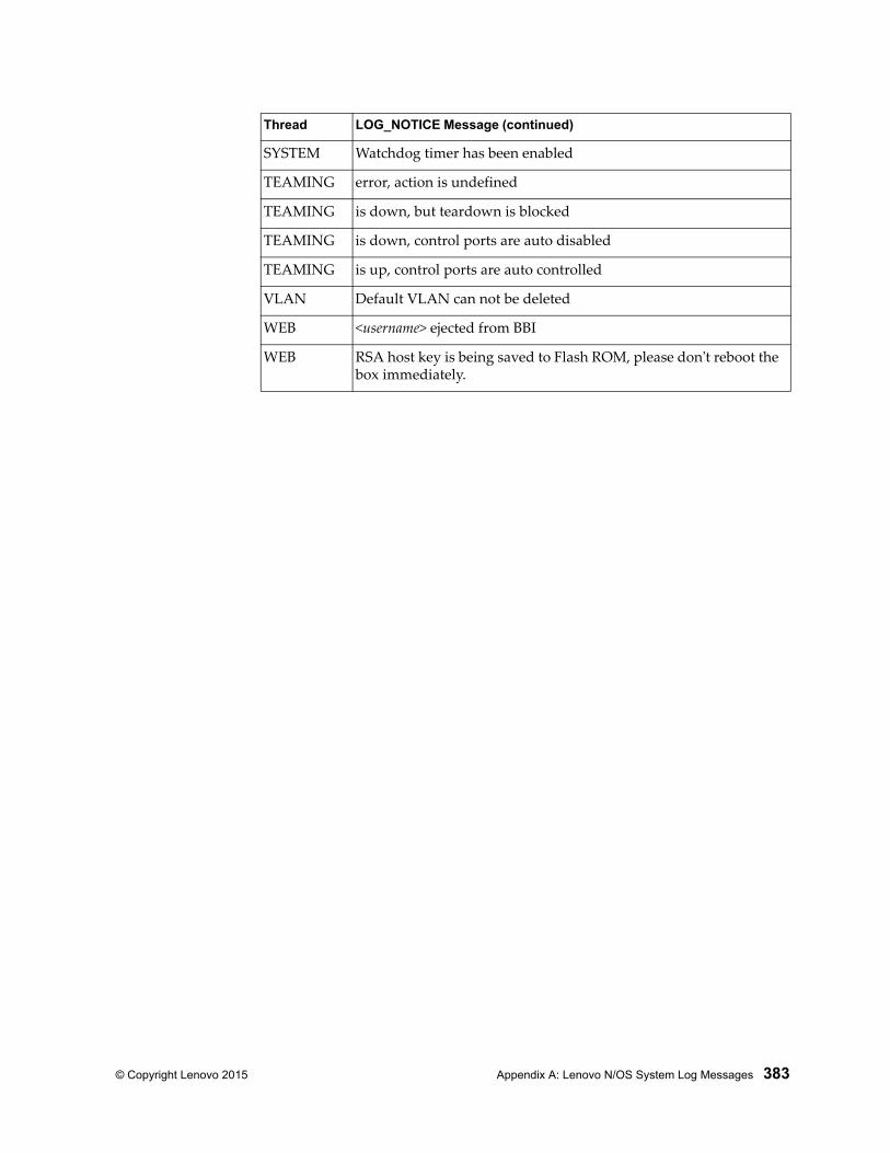
© Copyright Lenovo 2015 Appendix A: Lenovo N/OS System Log Messages 383
SYSTEM Watchdog timer has been enabled
TEAMING error, action is undefined
TEAMING is down, but teardown is blocked
TEAMING is down, control ports are auto disabled
TEAMING is up, control ports are auto controlled
VLAN Default VLAN can not be deleted
WEB <username> ejected from BBI
WEB RSA host key is being saved to Flash ROM, please don't reboot the box immediately.
Thread LOG_NOTICE Message (continued)
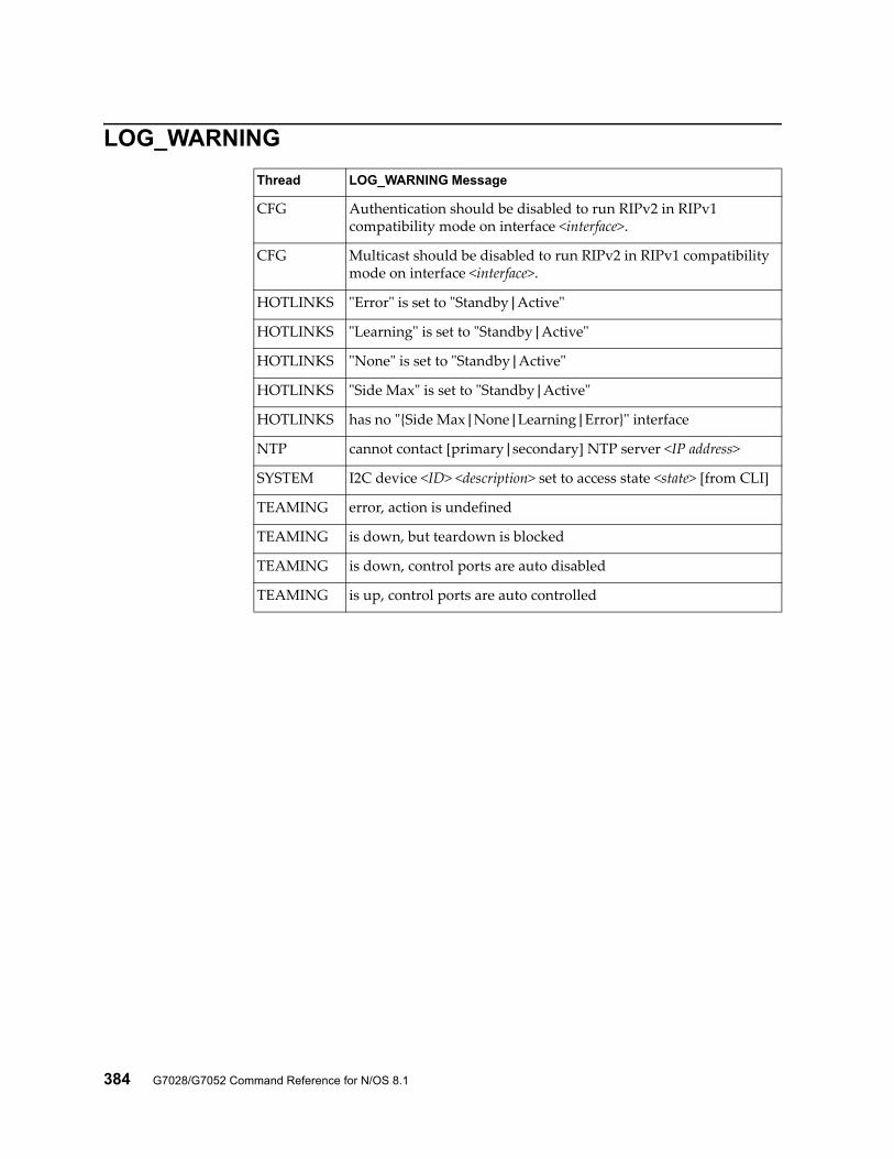
384 G7028/G7052 Command Reference for N/OS 8.1
LOG_WARNING
Thread LOG_WARNING Message
CFG Authentication should be disabled to run RIPv2 in RIPv1 compatibility mode on interface <interface>.
CFG Multicast should be disabled to run RIPv2 in RIPv1 compatibility mode on interface <interface>.
HOTLINKS "Error" is set to "Standby|Active"
HOTLINKS "Learning" is set to "Standby|Active"
HOTLINKS "None" is set to "Standby|Active"
HOTLINKS "Side Max" is set to "Standby|Active"
HOTLINKS has no "{Side Max|None|Learning|Error}" interface
NTP cannot contact [primary|secondary] NTP server <IP address>
SYSTEM I2C device <ID> <description> set to access state <state> [from CLI]
TEAMING error, action is undefined
TEAMING is down, but teardown is blocked
TEAMING is down, control ports are auto disabled
TEAMING is up, control ports are auto controlled
© Copyright Lenovo 2015 385
Appendix B. Getting help and technical assistance
If you need help, service or technical assistance, or just want more information about Lenovo products, you will find a wide variety of sources available from Lenovo to assist you.
Use this information to obtain additional information about Lenovo and Lenovo products, and determine what to do if you experience a problem with your Lenovo system or optional device.Note: This section includes references to IBM web sites and information about obtaining service. IBM is Lenovo's preferred service provider for the System x, Flex System, and NeXtScale System products.
Before you call, make sure that you have taken these steps to try to solve the problem yourself.
If you believe that you require warranty service for your Lenovo product, the service technicians will be able to assist you more efficiently if you prepare before you call.
Check all cables to make sure that they are connected.
Check the power switches to make sure that the system and any optional devices are turned on.
Check for updated software, firmware, and operating-system device drivers for your Lenovo product. The Lenovo Warranty terms and conditions state that you, the owner of the Lenovo product, are responsible for maintaining and updating all software and firmware for the product (unless it is covered by an additional maintenance contract). Your service technician will request that you upgrade your software and firmware if the problem has a documented solution within a software upgrade.
If you have installed new hardware or software in your environment, check the IBM ServerProven website to make sure that the hardware and software is supported by your product.
Go to the IBM Support portal to check for information to help you solve the problem.
Gather the following information to provide to the service technician. This data will help the service technician quickly provide a solution to your problem and ensure that you receive the level of service for which you might have contracted. Hardware and Software Maintenance agreement contract numbers, if
applicable Machine type number (Lenovo 4-digit machine identifier) Model number Serial number Current system UEFI and firmware levels Other pertinent information such as error messages and logs
386 G7028/G7052 Command Reference for N/OS 8.1
Start the process of determining a solution to your problem by making the pertinent information available to the service technicians. The IBM service technicians can start working on your solution as soon as you have completed and submitted an Electronic Service Request.
You can solve many problems without outside assistance by following the troubleshooting procedures that Lenovo provides in the online help or in the Lenovo product documentation. The Lenovo product documentation also describes the diagnostic tests that you can perform. The documentation for most systems, operating systems, and programs contains troubleshooting procedures and explanations of error messages and error codes. If you suspect a software problem, see the documentation for the operating system or program.
© Copyright Lenovo 2015 387
Appendix C. Notices
Lenovo may not offer the products, services, or features discussed in this document in all countries. Consult your local Lenovo representative for information on the products and services currently available in your area.
Any reference to a Lenovo product, program, or service is not intended to state or imply that only that Lenovo product, program, or service may be used. Any functionally equivalent product, program, or service that does not infringe any Lenovo intellectual property right may be used instead. However, it is the user's responsibility to evaluate and verify the operation of any other product, program, or service.
Lenovo may have patents or pending patent applications covering subject matter described in this document. The furnishing of this document does not give you any license to these patents. You can send license inquiries, in writing, to:
Lenovo (United States), Inc.1009 Think Place - Building OneMorrisville, NC 27560U.S.A.Attention: Lenovo Director of Licensing
LENOVO PROVIDES THIS PUBLICATION “AS IS” WITHOUT WARRANTY OF ANY KIND, EITHER EXPRESS OR IMPLIED, INCLUDING, BUT NOT LIMITED TO, THE IMPLIED WARRANTIES OF NON-INFRINGEMENT, MERCHANTABILITY OR FITNESS FOR A PARTICULAR PURPOSE. Some jurisdictions do not allow disclaimer of express or implied warranties in certain transactions, therefore, this statement may not apply to you.
This information could include technical inaccuracies or typographical errors. Changes are periodically made to the information herein; these changes will be incorporated in new editions of the publication. Lenovo may make improvements and/or changes in the product(s) and/or the program(s) described in this publication at any time without notice.
The products described in this document are not intended for use in implantation or other life support applications where malfunction may result in injury or death to persons. The information contained in this document does not affect or change Lenovo product specifications or warranties.
Nothing in this document shall operate as an express or implied license or indemnity under the intellectual property rights of Lenovo or third parties. All information contained in this document was obtained in specific environments and is presented as an illustration. The result obtained in other operating environments may vary.
Lenovo may use or distribute any of the information you supply in any way it believes appropriate without incurring any obligation to you.
Any references in this publication to non-Lenovo Web sites are provided for convenience only and do not in any manner serve as an endorsement of those Web sites. The materials at those Web sites are not part of the materials for this Lenovo product, and use of those Web sites is at your own risk.

388 G7028/G7052 Command Reference for N/OS 8.1
Any performance data contained herein was determined in a controlled environment. Therefore, the result obtained in other operating environments may vary significantly. Some measurements may have been made on development-level systems and there is no guarantee that these measurements will be the same on generally available systems. Furthermore, some measurements may have been estimated through extrapolation. Actual results may vary. Users of this document should verify the applicable data for their specific environment.
© Copyright Lenovo 2015 Appendix C: Notices 389
TrademarksLenovo, the Lenovo logo, Flex System, System x, NeXtScale System, and X-Architecture are trademarks of Lenovo in the United States, other countries, or both.
Intel and Intel Xeon are trademarks of Intel Corporation in the United States, other countries, or both.
Internet Explorer, Microsoft, and Windows are trademarks of the Microsoft group of companies.
Linux is a registered trademark of Linus Torvalds.
Other company, product, or service names may be trademarks or service marks of others.
390 G7028/G7052 Command Reference for N/OS 8.1
Important NotesProcessor speed indicates the internal clock speed of the microprocessor; other factors also affect application performance.
CD or DVD drive speed is the variable read rate. Actual speeds vary and are often less than the possible maximum.
When referring to processor storage, real and virtual storage, or channel volume, KB stands for 1 024 bytes, MB stands for 1 048 576 bytes, and GB stands for 1 073 741 824 bytes.
When referring to hard disk drive capacity or communications volume, MB stands for 1 000 000 bytes, and GB stands for 1 000 000 000 bytes. Total user-accessible capacity can vary depending on operating environments.
Maximum internal hard disk drive capacities assume the replacement of any standard hard disk drives and population of all hard-disk-drive bays with the largest currently supported drives that are available from Lenovo.
Maximum memory might require replacement of the standard memory with an optional memory module.
Each solid-state memory cell has an intrinsic, finite number of write cycles that the cell can incur. Therefore, a solid-state device has a maximum number of write cycles that it can be subjected to, expressed as total bytes written (TBW). A device that has exceeded this limit might fail to respond to system-generated commands or might be incapable of being written to. Lenovo is not responsible for replacement of a device that has exceeded its maximum guaranteed number of program/erase cycles, as documented in the Official Published Specifications for the device.
Lenovo makes no representations or warranties with respect to non-Lenovo products. Support (if any) for the non-Lenovo products is provided by the third party, not Lenovo.
Some software might differ from its retail version (if available) and might not include user manuals or all program functionality.

© Copyright Lenovo 2015 Appendix C: Notices 391
Recycling InformationLenovo encourages owners of information technology (IT) equipment to responsibly recycle their equipment when it is no longer needed. Lenovo offers a variety of programs and services to assist equipment owners in recycling their IT products. For information on recycling Lenovo products, go to:
http://www.lenovo.com/recycling
392 G7028/G7052 Command Reference for N/OS 8.1
Particulate ContaminationAttention: Airborne particulates (including metal flakes or particles) and reactive gases acting alone or in combination with other environmental factors such as humidity or temperature might pose a risk to the device that is described in this document.
Risks that are posed by the presence of excessive particulate levels or concentrations of harmful gases include damage that might cause the device to malfunction or cease functioning altogether. This specification sets forth limits for particulates and gases that are intended to avoid such damage. The limits must not be viewed or used as definitive limits, because numerous other factors, such as temperature or moisture content of the air, can influence the impact of particulates or environmental corrosives and gaseous contaminant transfer. In the absence of specific limits that are set forth in this document, you must implement practices that maintain particulate and gas levels that are consistent with the protection of human health and safety. If Lenovo determines that the levels of particulates or gases in your environment have caused damage to the device, Lenovo may condition provision of repair or replacement of devices or parts on implementation of appropriate remedial measures to mitigate such environmental contamination. Implementation of such remedial measures is a customer responsibility..
Contaminant Limits
Particulate • The room air must be continuously filtered with 40% atmospheric dust spot efficiency (MERV 9) according to ASHRAE Standard 52.21.
• Air that enters a data center must be filtered to 99.97% efficiency or greater, using high-efficiency particulate air (HEPA) filters that meet MIL-STD-282.
• The deliquescent relative humidity of the particulate contamination must be more than 60%2.
• The room must be free of conductive contamination such as zinc whis-kers.
Gaseous • Copper: Class G1 as per ANSI/ISA 71.04-19853
• Silver: Corrosion rate of less than 300 Å in 30 days
1 ASHRAE 52.2-2008 - Method of Testing General Ventilation Air-Cleaning Devices for Removal Efficiency by Particle Size. Atlanta: American Society of Heating, Refrigerating and Air-Con-ditioning Engineers, Inc.2 The deliquescent relative humidity of particulate contamination is the relative humidity at which the dust absorbs enough water to become wet and promote ionic conduction.3 ANSI/ISA-71.04-1985. Environmental conditions for process measurement and control systems: Airborne contaminants. Instrument Society of America, Research Triangle Park, North Car-olina, U.S.A.

© Copyright Lenovo 2015 Appendix C: Notices 393
Telecommunication Regulatory StatementThis product may not be certified in your country for connection by any means whatsoever to interfaces of public telecommunications networks. Further certification may be required by law prior to making any such connection. Contact a Lenovo representative or reseller for any questions.

394 G7028/G7052 Command Reference for N/OS 8.1
Electronic Emission NoticesWhen you attach a monitor to the equipment, you must use the designated monitor cable and any interference suppression devices that are supplied with the monitor.
Federal Communications Commission (FCC) Statement
Note: This equipment has been tested and found to comply with the limits for a Class A digital device, pursuant to Part 15 of the FCC Rules. These limits are designed to provide reasonable protection against harmful interference when the equipment is operated in a commercial environment. This equipment generates, uses, and can radiate radio frequency energy and, if not installed and used in accordance with the instruction manual, may cause harmful interference to radio communications. Operation of this equipment in a residential area is likely to cause harmful interference, in which case the user will be required to correct the interference at his own expense.
Properly shielded and grounded cables and connectors must be used to meet FCC emission limits. Lenovo is not responsible for any radio or television interference caused by using other than recommended cables and connectors or by unauthorized changes or modifications to this equipment. Unauthorized changes or modifications could void the user’s authority to operate the equipment.
This device complies with Part 15 of the FCC Rules. Operation is subject to the following two conditions: (1) this device may not cause harmful interference, and (2) this device must accept any interference received, including interference that might cause undesired operation.
Industry Canada Class A Emission Compliance Statement
This Class A digital apparatus complies with Canadian ICES-003.
Avis de Conformité à la Réglementation d'Industrie Canada
Cet appareil numérique de la classe A est conforme à la norme NMB-003 du Canada.
Australia and New Zealand Class A Statement
Attention: This is a Class A product. In a domestic environment this product may cause radio interference in which case the user may be required to take adequate measures.
European Union EMC Directive Conformance Statement
This product is in conformity with the protection requirements of EU Council Directive 2004/108/EC on the approximation of the laws of the Member States relating to electromagnetic compatibility. Lenovo cannot accept responsibility for any failure to satisfy the protection requirements resulting from a non-recommended modification of the product, including the installation of option cards from other manufacturers.
© Copyright Lenovo 2015 Appendix C: Notices 395
This product has been tested and found to comply with the limits for Class A Information Technology Equipment according to European Standard EN 55022. The limits for Class A equipment were derived for commercial and industrial environments to provide reasonable protection against interference with licensed communication equipment.
Lenovo, Einsteinova 21, 851 01 Bratislava, Slovakia
Germany Class A Statement
Zulassungsbescheinigung laut dem Deutschen Gesetz über die elektromagnetische Verträglichkeit von Betriebsmitteln, EMVG vom 20. Juli 2007 (früher Gesetz über die elektromagnetische Verträglichkeit von Geräten), bzw. der EMV EG Richtlinie 2004/108/EC (früher 89/336/EWG), für Geräte der Klasse A.
Dieses Gerät ist berechtigt, in übereinstimmung mit dem Deutschen EMVG das EG-Konformitätszeichen - CE - zu führen. Verantwortlich für die Konformitätserklärung nach Paragraf 5 des EMVG ist die Lenovo (Deutschland) GmbH, Gropiusplatz 10, D-70563 Stuttgart.
Informationen in Hinsicht EMVG Paragraf 4 Abs. (1) 4:
Das Gerät erfüllt die Schutzanforderungen nach EN 55024 und EN 55022 Klasse A.
Nach der EN 55022: “Dies ist eine Einrichtung der Klasse A. Diese Einrichtung kann im Wohnbereich Funkstörungen verursachen; in diesem Fall kann vom Betreiber verlangt werden, angemessene Maßnahmen durchzuführen und dafür aufzukommen.”
Nach dem EMVG: Dieses Produkt entspricht den Schutzanforderungen der EU-Richtlinie 2004/108/EG (früher 89/336/EWG) zur Angleichung der Rechtsvorschriften über die elektromagnetische Verträglichkeit in den EU-Mitgliedsstaaten und hält die Grenzwerte der EN 55022 Klasse A ein.
Um dieses sicherzustellen, sind die Geräte wie in den Handbüchern beschrieben zu installieren und zu betreiben. Des Weiteren dürfen auch nur von der Lenovo empfohlene Kabel angeschlossen werden. Lenovo übernimmt keine Verantwortung für die Einhaltung der Schutzanforderungen, wenn das Produkt ohne Zustimmung der Lenovo verändert bzw. wenn Erweiterungskomponenten von Fremdherstellern ohne Empfehlung der Lenovo gesteckt/eingebaut werden.
Deutschland:
Einhaltung des Gesetzes über die elektromagnetische Verträglichkeit von Betriebsmittein Dieses Produkt entspricht dem “Gesetz über die elektromagnetische Verträglichkeit von Betriebsmitteln” EMVG (früher “Gesetz über die elektromagnetische Verträglichkeit von Geräten"). Dies ist die Umsetzung der EU-Richtlinie 2004/108/EG (früher 89/336/EWG) in der Bundesrepublik Deutschland.
396 G7028/G7052 Command Reference for N/OS 8.1
Zulassungsbescheinigung laut dem Deutschen Gesetz über die elektromagnetische Verträglichkeit von Betriebsmitteln, EMVG vom 20. Juli 2007 (früher Gesetz über die elektromagnetische Verträglichkeit von Geräten), bzw. der EMV EG Richtlinie 2004/108/EC (früher 89/336/EWG), für Geräte der Klasse A.
Dieses Gerät ist berechtigt, in übereinstimmung mit dem Deutschen EMVG das EG-Konformitätszeichen - CE - zu führen. Verantwortlich für die Konformitätserklärung nach Paragraf 5 des EMVG ist die Lenovo (Deutschland) GmbH, Gropiusplatz 10, D-70563 Stuttgart.
Informationen in Hinsicht EMVG Paragraf 4 Abs. (1) 4: Das Gerät erfüllt die Schutzanforderungen nach EN 55024 und EN 55022 Klasse A.
Nach der EN 55022: “Dies ist eine Einrichtung der Klasse A. Diese Einrichtung kann im Wohnbereich Funkstörungen verursachen; in diesem Fall kann vom Betreiber verlangt werden, angemessene Maßnahmen durchzuführen und dafür aufzukommen."
Nach dem EMVG: “Geräte dürfen an Orten, für die sie nicht ausreichend entstört sind, nur mit besonderer Genehmigung des Bundesministers für Post und Telekommunikation oder des Bundesamtes für Post und Telekommunikation betrieben werden. Die Genehmigung wird erteilt, wenn keine elektromagnetischen Störungen zu erwarten sind.” (Auszug aus dem EMVG, Paragraph 3, Abs. 4). Dieses Genehmigungsverfahren ist nach Paragraph 9 EMVG in Verbindung mit der entsprechenden Kostenverordnung (Amtsblatt 14/93) kostenpflichtig.
Anmerkung: Um die Einhaltung des EMVG sicherzustellen sind die Geräte, wie in den Handbüchern angegeben, zu installieren und zu betreiben.
Japan VCCI Class A Statement
This is a Class A product based on the standard of the Voluntary Control Council for Interference (VCCI). If this equipment is used in a domestic environment, radio interference may occur, in which case the user may be required to take corrective actions.

© Copyright Lenovo 2015 Appendix C: Notices 397
Japan Electronics and Information Technology Industries Association (JEITA) Statement
Japan Electronics and Information Technology Industries Association (JEITA) Confirmed Harmonics Guidelines (products less than or equal to 20 A per phase)
Japan Electronics and Information Technology Industries Association (JEITA) Confirmed Harmonics Guidelines with Modifications (products greater than 20 A per phase).
Korea Communications Commission (KCC) Statement
This is electromagnetic wave compatibility equipment for business (Type A). Sellers and users need to pay attention to it. This is for any areas other than home.

398 G7028/G7052 Command Reference for N/OS 8.1
Russia Electromagnetic Interference (EMI) Class A statement

© Copyright Lenovo 2015 Appendix C: Notices 399
People’s Republic of China Class A electronic emission statement

400 G7028/G7052 Command Reference for N/OS 8.1
Taiwan Class A compliance statement
© Copyright Lenovo 2015 Index 401
Index
Numerics802.1p
ACL and TOS mapping 252configuration 236DSCP configuration 238information 87priority level 224, 244
IPv6 254priority value 236re-marking the value 252re-marking the value (IPv6) 258
802.1xconfiguration 266control plane protection 239guest VLAN configuration 269information 47port configuration 270RADIUS server timeout 268Spanning Tree information 63
Aabbreviating commands (CLI) 23access control
user 218ACL
IPv6 254log configuration 260meter configuration 251port commands 233port metering 251port mirroring 245port re-mark configuration 252re-marking (IPv6) 258statistics 166, 167
active configuration block 177, 348active port
LACP 299active switch configuration
gtcfg 336ptcfg 335restoring 336saving and loading 336
administrator account 24assistance, getting 385Australia Class A statement 394
Bbackup configuration block 348Boot Management menu 351Boot options 341 to ??bridge priority 68, 70Bridge Protocol Data Unit (BPDU) 68, 69, 70, 279
Bridge Spanning-Tree parameters 280
CCanada Class A electronic emission statement 394China Class A electronic emission statement 399Cisco Ether Channel 290CIST information 70Class A electronic emission notice 394clear
counters for all interfaces and queues 103CPU use statistics 101dump information 370FDB statistics 124hot links statistics 124IPv4 statistics 132IPv6 statistics 132LACP statistics 124MP-related statistics 101port statistics 101, 104statistics for all ports 103trunk group statistics 122vLAG statistics 129
CLI Display 30command (help) 20commands
abbreviations 23conventions used in this manual 14modes 18shortcuts 23tab completion 23
configurationcommands 175 to ??default gateway interval, for health checks 315default gateway IP address 315dump command 334failover 300global 18LACP 298port link speed 230port mirroring 265port trunking 290save changes 177switch IP address 313VLAN default (PVID) 227VLAN IP interface 314VLAN tagging 226
configuration blockactive 348backup 348factory 348selection 348
contamination, particulate and gaseous 392control plane protection (CoPP) 239COS, queue informationClass of Service (see COS) 87
402 G7028/G7052 Command Reference for N/OS 8.1
cost (STP information) 64, 66, 71CPU
statistics 162statistics history 163use 162use history 163
Ddaylight savings time 179debugging 359default gateway
information 75default gateway, interval (for health checks) 315default password 24delete
counters for all interfaces and queues 103CPU use statistics 101FDB entry 361FDB statistics 124hot links statistics 124IPv4 statistics 132IPv6 statistics 132LACP statistics 124MP-related statistics 101port statistics 101, 104statistics for all ports 103trunk group statistics 122vLAG statistics 129
DHCPcontrol plane protection 239
DISC (port state) 64, 66disconnect idle timeout 25downloading software 346DSB (port state) 66dump
configuration command 334maintenance 359
duplex mode, link status 27, 97
EECN (Explicit Congestion Notification) 241electronic emission Class A notice 394error disable and recovery
port 229system 183
EtherChannel, with port trunking 290European Union EMC Directive conformance statement
394Explicit Congestion Notification (ECN) 241
Ffactory configuration block 348failover
configuration 300manual monitor control configuration 302manual monitor port configuration 301trigger configuration 300
FCC Class A notice 394FCC, Class A 394FDB
delete entry 361maintenance 361managing information 359statistics 125
flow control 27, 97CBP discards 115IBP discards 115pause packets 113, 114setting 230
forwardingdatabase (see FDB) 125database, delete entry 361FDB maintenance 361state (FWD) 51, 72
Forwarding Database (see FDB) 49forwarding state
(FWD) 68, 69, 71FWD (port state) 64, 66fwd (STP bridge option) 279FwdDel (forward delay), bridge port 68, 69, 71
Ggaseous contamination 392gateway
default gateway configuration (IPv4) 315IPv6 329
Germany Class A statement 395getting help 385gtcfg (TFTP load command) 336
Hhealth checks
default gateway interval, retries 315retry, number of failed health checks 315
hello (STP information) 68, 69, 70help
online 20sources of 385
help, getting 385Hot Links configuration 303HTTPS 221
© Copyright Lenovo 2015 Index 403
IICMP
control plane protection 239statistics 141
idle timeout, setting 25IEEE standards
802.1x 47, 63IGMP
advanced parameters 323configuration 317control plane protection 239information 77multicast router information 80querier 324querier information 79snooping 318statistics 146
imagedownloading 346software, selecting 347
information commands 27 to ??IP address
invalid 116invalid (IPv4) 133invalid (IPv6) 136
IP forwardinginformation 75
IP information 75, 84IP interface
address of default gateway 315configuration mode 18configuring address 313configuring VLANs 314information 75network filter configuration 316
IPMCdisplay all groups registered 76group information 81
IPv4clear statistics 132statistics 133
IPv6ACL configuration 254clear statistics 132default gateway configuration 329re-mark configuration 258statistics 135
ISCLI commandsbasics 17 to 25modes 18
JJapan Class A electronic emission statement 396Japan Electronics and Information Technology Indus-
tries Association statement 397JEITA statement 397
KKorea Class A electronic emission statement 397
LLACP
clear statistics 124configuration 298control plane protection 239information 52interface portchannel mode 224logged packet statistics 157statistics 123, 126vLAG information 61
Layer 2 commands 44Layer 3 commands 75LDAP
configuration 197server address 197
LED, Service Required 180Lightweight Directory Access Protocol (see LDAP) 197Link Aggregation Control Protocol (see LACP) 123Link Flap Dampening (LFD) 184Link Layer Detection Protocol (see LLDP) 123link speed, configuring 230link status 27
command 97duplex mode 27, 97information 97port speed 27, 97
linkt (SNMP option) 203LLDP
configuration 286information 57statistics 123, 128
logsACL 260clear 150syslog messages 186
LRN (port state) 64, 66, 68, 69, 71
MMAC address 29, 41, 49, 361
multicast configuration 283Maintenance commands 359 to 371manual style conventions 14MaxAge (STP information) 68, 69, 70Media Access Control address (see MAC) 49Miscellaneous Debug commands 362monitor port 265MP
clear statistics 101debug commands 362display MAC address 29, 41packet 151packet statistics 150processor statistics 148
404 G7028/G7052 Command Reference for N/OS 8.1
multicastMAC 283router information 80
mxage (STP bridge option) 279
NNew Zealand Class A statement 394notes, important 390notice 180notices 387NTP synchronization 199
Oonline help 20Operations commands 339 to ??operations-level
port options 340
Pparticulate contamination 392passwords 24
administrator account 24default 24user access control 218user account 24
path-cost (STP port option) 281People’s Republic of China Class A electronic emission
statement 399ping 21port
802.1x configuration 270ACL meter 251configuration 224configuration mode 18disabling (temporarily) 231ECN configuration 234Error Disable and Recovery 229information 98link configuration 230membership of the VLAN 46, 74mirroring
ACLs 245configuration 265
number 97operations-level options 340priority 64, 71speed 27, 97states 51trunking
configuration 290description 290
VLAN ID 27, 98WRED configuration 234
preemptionhot links 304
Private VLAN 310protocol-based VLAN configuration 308ptcfg (TFTP save command) 335PVID (port VLAN ID) 27, 98
RRADIUS
802.1x server timeout 268server configuration 190statistics 157vs TACACS+ 192
read community string (SNMP option) 203receive flow control 230reference ports 51re-mark
ACL port re-mark menu 252IPv6 ACL 258
Remonte Monitoring (see RMON) 103retry
health checks for default gateway 315RADIUS server 190
RMONalarm configuration 332alarm information 95configuration 330event configuration 331event information 96history 94history configuration 330information 93port information 98statistics 103, 117
route mapinformation 84
RSTP informationMSTP informationRapid SpanningTree informationMultiple Spanning Tree information66
Russia Class A electronic emission statement 398
Ssave (global command) 177secret
RADIUS server 190Secure Shell 189service and support
before you call 385Service Required LED 180shortcuts (CLI) 23snap traces
buffer 362SNMP
configuration 202display packets logged 158options 202parameters, modifying 202statistics 101, 168

© Copyright Lenovo 2015 Index 405
SNMPv3community table configuration 211community table information 36configuration 205group configuration 210information 32notify table configuration 214target address table configuration 212target address table information 37target parameters table configuration 213view configuration 208
softwareimage 345image file and version 29, 41
state (STP information) 64, 66, 71static
multicast MAC configuration 283Statistics commands 101 to 174STP 72
blocked ports information 45bridge parameters 280bridge priority 68, 70configuration 272information 45, 274link type 65path-cost option 281root bridge 68, 70, 280root information 46RSTP/PVRST 278switch reset effect 350
subnetIP interface 313performance 109
switchname and location 29, 41resetting 350
systemcontact (SNMP option) 202date and time 29, 41information 41location (SNMP option) 203
System Error Disable and Recovery 183System Information 28System Log Messages 373 to 384system options
tnport 215
Ttab completion (CLI) 23TACACS+ 192Taiwan Class A electronic emission statement 400TCP
ECN 234header parameters 91statistics 131, 143, 159statistics, clearing 132TACACS+ 192WRED thresholds 235
technical assistance 385telnet
configuring switches using 334radius server 190, 197
text conventions 14TFTP 346
PUT and GET commands 335server 335
timeoutidle connection 25radius server 191
trace buffer 362traceroute 20trademarks 389transceiver status 99trunk group information 72typographic conventions, manual 14
UUCB statistics 160UDLD
configuration 232information 59
UDPstatistics 145
UniDirectional Link Detection 232United States FCC Class A notice 394unknown (UNK) port state 51Unscheduled System Dump 371upgrade
switch software 345USB Boot 344USB Copy 337USB drive 337, 344user access control configuration 218user account 24
VVirtual Link Aggregation Control Protocol (see vLAG)
46vLAG
clear statistics 129configuration 294control plane protection 239information 46

406 G7028/G7052 Command Reference for N/OS 8.1
VLANconfiguration 307configuration mode 19information 74name 46, 74port membership 46, 74protocol-based, configuration 308setting access VLAN 226setting default number (PVID) 227tagging 27, 98
port configuration 226port restrictions 308
VLAN Number 74
Wwatchdog timer 359Weighted Random Early Detection (see WRED) 241WRED
configuration 241transmit queue configuration 235, 242
write community string (SNMP option) 204