Embed Size (px)
Citation preview
Islington Substation
Control Room Fire Recovery Plan
Prepared for
Transpower NZ Ltd Doc: MEL-R1077 Rev 00
Project: TLM7240
August 2011
P O Box 25 008
Christchurch Ph 379 2129
Fax 377 2874
e s l a
ine Tec h
i t t o n
C o n s u l t i n gML
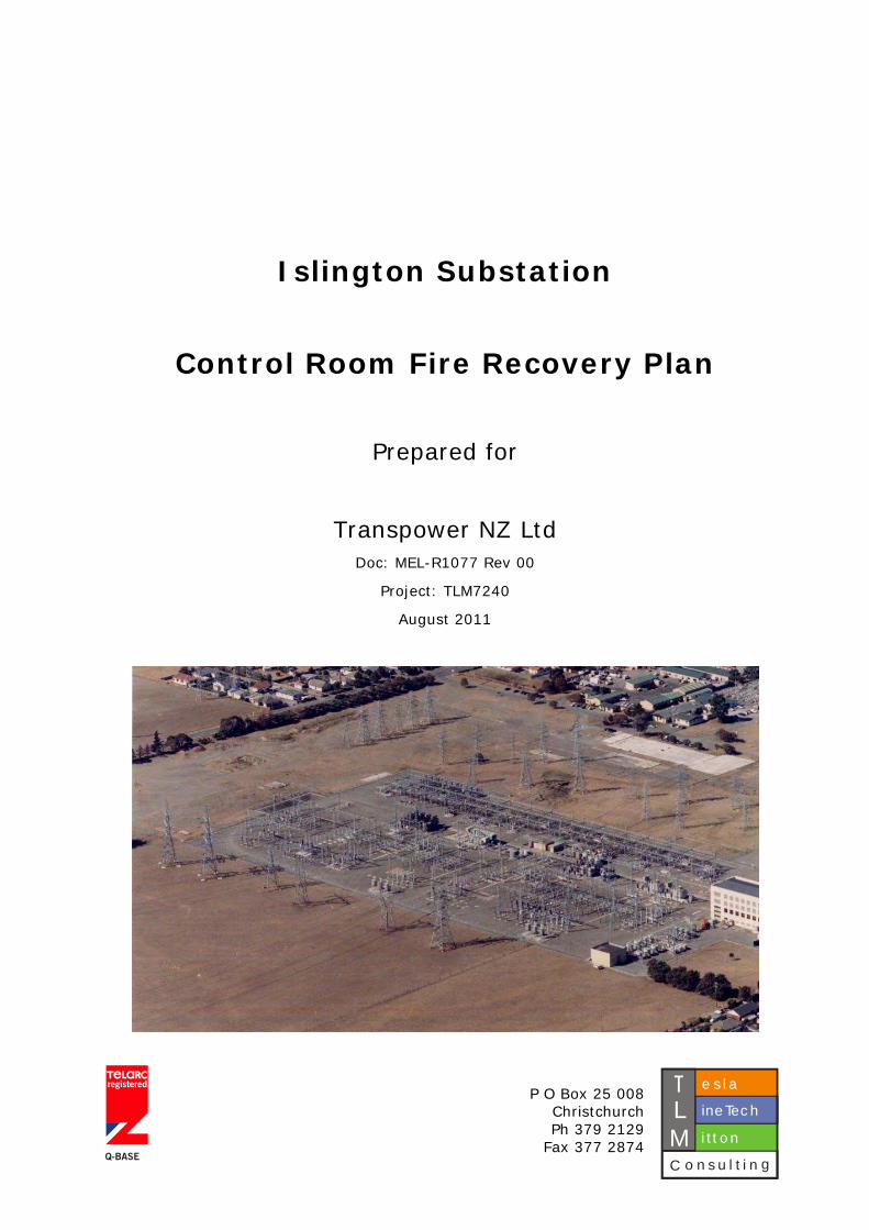
Quality Assurance Record
Contract Description: Islington Control Room Fire Recovery Plan
Contract Number: MMS: ISL-STNS
Document Number: MEL-R1077 Rev 00
Project Reference: TLM7240
Revision Log
Rev Date Description Signed Name
Prepared A. Brailsford
Reviewed
J. English
00 24/08/11 First issue to Client
Approved
J. English
© TLM Consulting Ltd Page 2 of 33 MEL-R1077 Rev 00, August 2011
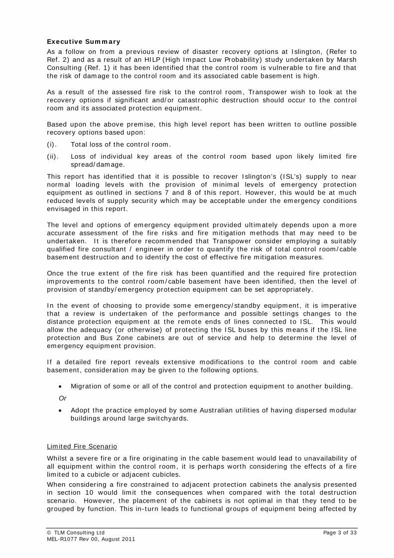
Executive Summary
As a follow on from a previous review of disaster recovery options at Islington, (Refer to Ref. 2) and as a result of an HILP (High Impact Low Probability) study undertaken by Marsh Consulting (Ref. 1) it has been identified that the control room is vulnerable to fire and that the risk of damage to the control room and its associated cable basement is high. As a result of the assessed fire risk to the control room, Transpower wish to look at the recovery options if significant and/or catastrophic destruction should occur to the control room and its associated protection equipment. Based upon the above premise, this high level report has been written to outline possible recovery options based upon:
(i). Total loss of the control room.
(ii). Loss of individual key areas of the control room based upon likely limited fire spread/damage.
This report has identified that it is possible to recover Islington’s (ISL’s) supply to near normal loading levels with the provision of minimal levels of emergency protection equipment as outlined in sections 7 and 8 of this report. However, this would be at much reduced levels of supply security which may be acceptable under the emergency conditions envisaged in this report. The level and options of emergency equipment provided ultimately depends upon a more accurate assessment of the fire risks and fire mitigation methods that may need to be undertaken. It is therefore recommended that Transpower consider employing a suitably qualified fire consultant / engineer in order to quantify the risk of total control room/cable basement destruction and to identify the cost of effective fire mitigation measures. Once the true extent of the fire risk has been quantified and the required fire protection improvements to the control room/cable basement have been identified, then the level of provision of standby/emergency protection equipment can be set appropriately. In the event of choosing to provide some emergency/standby equipment, it is imperative that a review is undertaken of the performance and possible settings changes to the distance protection equipment at the remote ends of lines connected to ISL. This would allow the adequacy (or otherwise) of protecting the ISL buses by this means if the ISL line protection and Bus Zone cabinets are out of service and help to determine the level of emergency equipment provision. If a detailed fire report reveals extensive modifications to the control room and cable basement, consideration may be given to the following options.
• Migration of some or all of the control and protection equipment to another building.
Or
• Adopt the practice employed by some Australian utilities of having dispersed modular buildings around large switchyards.
Limited Fire Scenario
Whilst a severe fire or a fire originating in the cable basement would lead to unavailability of all equipment within the control room, it is perhaps worth considering the effects of a fire limited to a cubicle or adjacent cubicles.
When considering a fire constrained to adjacent protection cabinets the analysis presented in section 10 would limit the consequences when compared with the total destruction scenario. However, the placement of the cabinets is not optimal in that they tend to be grouped by function. This in-turn leads to functional groups of equipment being affected by
© TLM Consulting Ltd Page 3 of 33 MEL-R1077 Rev 00, August 2011

© TLM Consulting Ltd Page 4 of 33 MEL-R1077 Rev 00, August 2011
very small fires and of particular concern is that the DC1/DC2 distribution is contained in adjacent cabinets which would mean that a small fire could render a complete loss of control & protection equipment due to complete d.c. supply shutdown.
Contents 1 Introduction .................................................................................................... 7 2 Background...................................................................................................... 7 3 Islington Substation ........................................................................................ 8 4 Consequences of Control Room Fire................................................................. 8
4.1 Power System Constraints Immediately Following a Major Fire incident .................9 5 Recovery Process............................................................................................. 9
5.1 Initial Recovery Objectives ........................................................................... 10 6 Recovery Options........................................................................................... 11
6.1 33 kV Network ............................................................................................ 12 7 Emergency Equipment Requirements ............................................................ 12
7.1 Minimum Transformer Protection ................................................................... 12 7.2 Provision of 66 kV Reactive Support............................................................... 13 7.3 Provision of 220 kV Reactive Support Equipment ............................................. 14
8 Emergency Equipment Installation ................................................................ 15 9 Communications Considerations .................................................................... 17 10 Limited Fire Damage Scenario...................................................................... 17 11 Summary...................................................................................................... 18 12 Recommendations........................................................................................ 18 13 References ................................................................................................... 19
Appendices Appendix A............................................................................................................ 21 Appendix B............................................................................................................ 31
© TLM Consulting Ltd Page 5 of 33 MEL-R1077 Rev 00, August 2011

Abbreviations
a.c. Alternating Current ADD Addington Substation ASB Ashburton Substation AVR Automatic Voltage Regulator BEN Benmore PS BRY Bromley Substation CB Circuit Breaker COB Cobb PS COL Coleridge PS d.c. Direct Current ESC Electrical Supply Company GXP Grid Exit Point HAY Haywards Substation HILP High impact Low Probability HV High Voltage IDRP Islington Substation Disaster Recovery Plan. (Ref. 2) ISL Islington Substation KKA Kaikoura Substation KIK Kikiwa Substation LTAC Low Tension Alternating Current (400 V AC system) LV Low Voltage ODJB Outdoor Junction Box PAP Papanui Substation PU Per Unit RTU Remote Terminal Unit SI South Island SPN Springston Substation SVC Static VAr Compensator TIM Timaru Substation TKB Tekapo B TWZ Twizel Substation WPR Waipara Substation
© TLM Consulting Ltd Page 6 of 33 MEL-R1077 Rev 00, August 2011
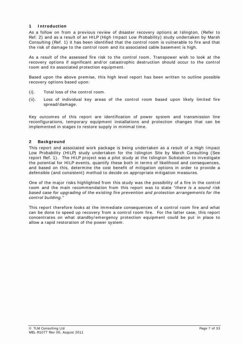
1 Introduction
As a follow on from a previous review of disaster recovery options at Islington, (Refer to Ref. 2) and as a result of an HILP (High Impact Low Probability) study undertaken by Marsh Consulting (Ref. 1) it has been identified that the control room is vulnerable to fire and that the risk of damage to the control room and its associated cable basement is high. As a result of the assessed fire risk to the control room, Transpower wish to look at the recovery options if significant and/or catastrophic destruction should occur to the control room and its associated protection equipment. Based upon the above premise, this high level report has been written to outline possible recovery options based upon: (i). Total loss of the control room.
(ii). Loss of individual key areas of the control room based upon likely limited fire spread/damage.
Key outcomes of this report are identification of power system and transmission line reconfigurations, temporary equipment installations and protection changes that can be implemented in stages to restore supply in minimal time. 2 Background This report and associated work package is being undertaken as a result of a High Impact Low Probability (HILP) study undertaken for the Islington Site by March Consulting (See report Ref. 1). The HILP project was a pilot study at the Islington Substation to investigate the potential for HILP events, quantify these both in terms of likelihood and consequences, and based on this, determine the cost benefit of mitigation options in order to provide a defensible (and consistent) method to decide on appropriate mitigation measures. One of the major risks highlighted from this study was the possibility of a fire in the control room and the main recommendation from this report was to state “there is a sound risk based case for upgrading of the existing fire prevention and protection arrangements for the control building.” This report therefore looks at the immediate consequences of a control room fire and what can be done to speed up recovery from a control room fire. For the latter case, this report concentrates on what standby/emergency protection equipment could be put in place to allow a rapid restoration of the power system.
© TLM Consulting Ltd Page 7 of 33 MEL-R1077 Rev 00, August 2011

3 Islington Substation
ISL is a major node for the central and northern South Island transmission and distribution system. The 220 kV bus is supplied by four circuits from southern generation sites and provides an interconnection to the three 220 kV circuits to KIK and beyond. Three 220/66 kV, interconnecting transformer banks supply an extensive 66 kV bus with 17 feeders. Two 220/33 kV interconnecting banks supply a 33 kV bus. The ISL 66 kV bus supplies various substations around Christchurch and Central Canterbury which in turn supply Orion, the local ESC who cover the area between the Rakaia River and the Waimakariri River, including all of Christchurch city. MainPower, who operate north of the Waimakariri River, are also supplied from 66 kV substations connected to ISL. In addition ISL features considerable reactive power (voltage) support equipment installed on the 220 kV and 66 kV busses including switchable capacitor banks, rotary condensers and SVC plant. 4 Consequences of Control Room Fire
Based upon the Islington Disaster Recovery Plan from 2009 (IDRP,), the immediate consequence of a catastrophic control room fire would be to render all control and protection associated with the 220 kV and 66 kV buses inoperable and effectively shutdown the substation. The immediate impact of loss of 220 and 66 kV buses was studied by the IDRP and found that following the transmission system disturbances when ISL is completely disabled, the System Operator would start re-building the South Island generation and distribution network not withstanding the loss of ISL.
a) The System Operator would start re-livening the South Island generation and distribution network where possible, including:
• All generation, transmission networks and loads south of TWZ. No load
limitations are envisaged.
• The West Coast supplied by COL and embedded generation. Black start capability may be required and load limitations would apply.
• The Nelson area, supplied by COB. Load limitations would apply.
• TIM, ASB and BRY substations.
b) With BRY livened, Orion would then be able to re-liven the following Christchurch
systems:
• The 66 kV BRY–ADD cable circuit to their Lancaster and Armagh Substations. From Armagh, the Orion 66 kV cables can back-feed Transpower’s ADD 66 kV bus providing limited supply out from ADD on other feeders.
• The Orion 66 kV cables used to supply ADD from their Armagh Substation are limited in capacity to 70 MVA total. This would be the limit of Orion’s support for ADD during all stages of this plan.
• 66 kV BRY - Halswell transmission lines to Heathcote and Halswell substations.
• Orion would then progressively close in feeders to essential loads from energised substations until they reach the load limits set by the System Operator.
© TLM Consulting Ltd Page 8 of 33 MEL-R1077 Rev 00, August 2011
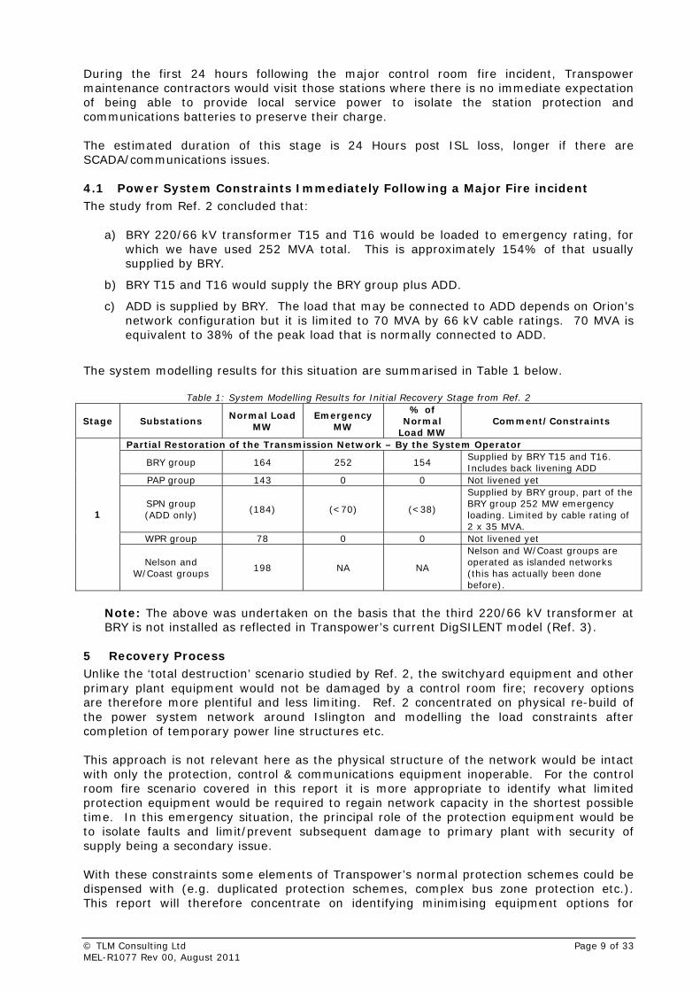
During the first 24 hours following the major control room fire incident, Transpower maintenance contractors would visit those stations where there is no immediate expectation of being able to provide local service power to isolate the station protection and communications batteries to preserve their charge. The estimated duration of this stage is 24 Hours post ISL loss, longer if there are SCADA/communications issues. 4.1 Power System Constraints Immediately Following a Major Fire incident The study from Ref. 2 concluded that:
a) BRY 220/66 kV transformer T15 and T16 would be loaded to emergency rating, for which we have used 252 MVA total. This is approximately 154% of that usually supplied by BRY.
b) BRY T15 and T16 would supply the BRY group plus ADD.
c) ADD is supplied by BRY. The load that may be connected to ADD depends on Orion’s network configuration but it is limited to 70 MVA by 66 kV cable ratings. 70 MVA is equivalent to 38% of the peak load that is normally connected to ADD.
The system modelling results for this situation are summarised in Table 1 below.
Table 1: System Modelling Results for Initial Recovery Stage from Ref. 2
Stage Substations Normal Load
MW Emergency
MW
% of Normal
Load MW Comment/Constraints
Partial Restoration of the Transmission Network – By the System Operator
BRY group 164 252 154 Supplied by BRY T15 and T16. Includes back livening ADD
PAP group 143 0 0 Not livened yet
SPN group (ADD only)
(184) (<70) (<38)
Supplied by BRY group, part of the BRY group 252 MW emergency loading. Limited by cable rating of 2 x 35 MVA.
WPR group 78 0 0 Not livened yet
1
Nelson and W/Coast groups
198 NA NA
Nelson and W/Coast groups are operated as islanded networks (this has actually been done before).
Note: The above was undertaken on the basis that the third 220/66 kV transformer at BRY is not installed as reflected in Transpower’s current DigSILENT model (Ref. 3).
5 Recovery Process Unlike the ‘total destruction’ scenario studied by Ref. 2, the switchyard equipment and other primary plant equipment would not be damaged by a control room fire; recovery options are therefore more plentiful and less limiting. Ref. 2 concentrated on physical re-build of the power system network around Islington and modelling the load constraints after completion of temporary power line structures etc. This approach is not relevant here as the physical structure of the network would be intact with only the protection, control & communications equipment inoperable. For the control room fire scenario covered in this report it is more appropriate to identify what limited protection equipment would be required to regain network capacity in the shortest possible time. In this emergency situation, the principal role of the protection equipment would be to isolate faults and limit/prevent subsequent damage to primary plant with security of supply being a secondary issue. With these constraints some elements of Transpower’s normal protection schemes could be dispensed with (e.g. duplicated protection schemes, complex bus zone protection etc.). This report will therefore concentrate on identifying minimising equipment options for
© TLM Consulting Ltd Page 9 of 33 MEL-R1077 Rev 00, August 2011
emergency placement, such as ‘containerised’ control & protection suites located in the switchyard. 5.1 Initial Recovery Objectives
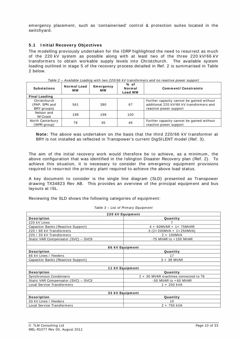
The modelling previously undertaken for the IDRP highlighted the need to resurrect as much of the 220 kV system as possible along with at least two of the three 220 kV/66 kV transformers to obtain workable supply levels into Christchurch. The available system loading outlined in stage 5 of the recovery process detailed in Ref. 2 is summarised in Table 2 below.
Table 2 – Available Loading with two 220/66 kV transformers and no reactive power support
Substations Normal Load
MW Emergency
MW
% of Normal
Load MW Comment/Constraints
Final Loading Christchurch
(PAP, SPN and BRY groups)
561 380 67 Further capacity cannot be gained without additional 220 kV/66 kV transformers and reactive power support
Nelson and W/Coast
198 198 100
North Canterbury (WPR group)
78 35 45 Further capacity cannot be gained without reactive power support
Note: The above was undertaken on the basis that the third 220/66 kV transformer at BRY is not installed as reflected in Transpower’s current DigSILENT model (Ref. 3).
The aim of the initial recovery work would therefore be to achieve, as a minimum, the above configuration that was identified in the Islington Disaster Recovery plan (Ref. 2). To achieve this situation, it is necessary to consider the emergency equipment provisions required to resurrect the primary plant required to achieve the above load status. A key document to consider is the single line diagram (SLD) presented as Transpower drawing TX34823 Rev AB. This provides an overview of the principal equipment and bus layouts at ISL. Reviewing the SLD shows the following categories of equipment:
Table 3 – List of Primary Equipment
220 kV Equipment Description Quantity 220 kV Lines 7 Capacitor Banks (Reactive Support) 4 × 60MVAR + 1× 75MVAR 220 / 66 kV Transformers 3 (2×200MVA + 1×250MVA) 220 / 33 kV Transformers 2 × 100MVA Static VAR Compensator (SVC) – SVC9 -75 MVAR to +150 MVAR
66 kV Equipment Description Quantity 66 kV Lines / Feeders 17 Capacitor Banks (Reactive Support) 3 × 38 MVAR
11 kV Equipment Description Quantity Synchronous Condensers 2 × 30 MVAR machines connected to T6 Static VAR Compensator (SVC) – SVC3 -50 MVAR to +60 MVAR Local Service Transformers 1 × 250 kVA
33 kV Equipment Description Quantity 33 kV Lines / Feeders 10 Local Service Transformers 2 × 750 kVA
© TLM Consulting Ltd Page 10 of 33 MEL-R1077 Rev 00, August 2011
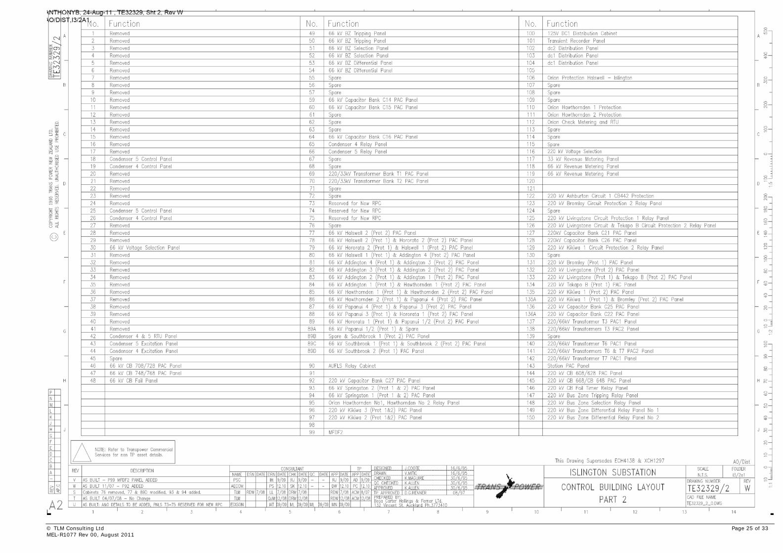
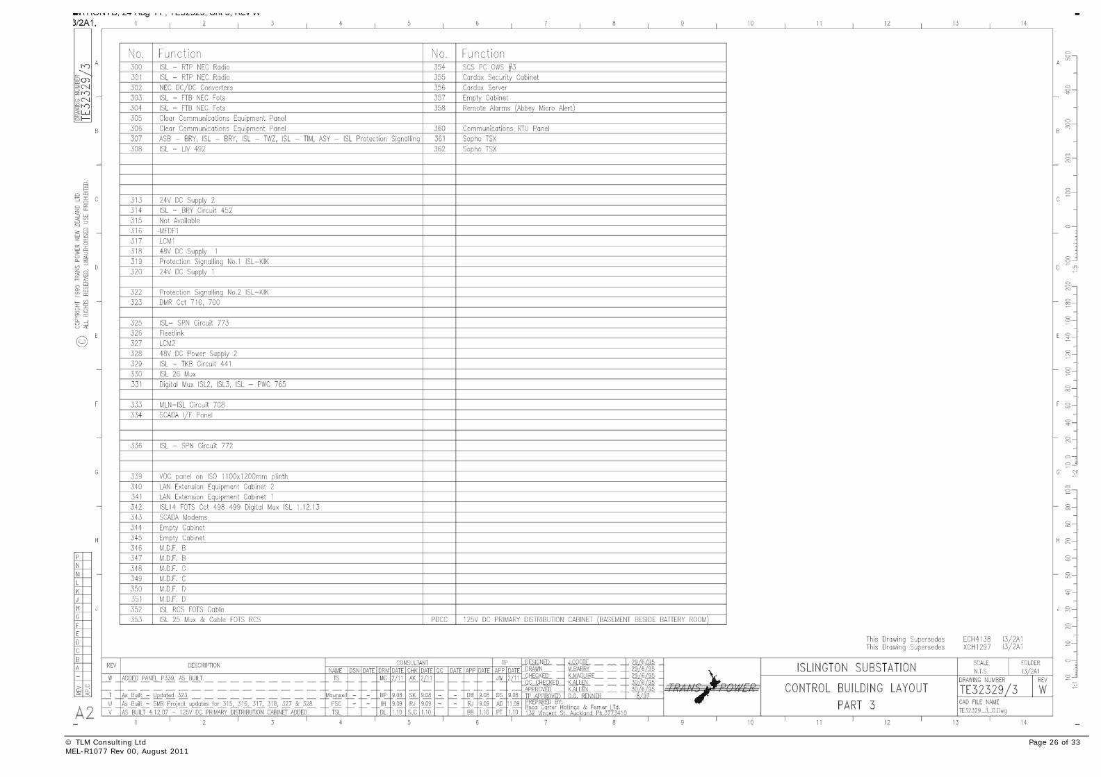
The next section of this report will therefore consider the recovery options available for restoring the above equipment at differing levels of emergency equipment provision along with a review of subsequent load constraints. 6 Recovery Options Given the total destruction the control room by fire, inspection of the control room building layout drawing (TE32329) reveals that much of the protection on ISL’s principal buses would be lost. In this situation, the key questions to be asked are: i) What parts of the system could be operated without the availability of the equipment
affected by the fire?
ii) What minimal levels of protection are necessary to allow supply restoration?
iii) What compromises can be made given that supply restoration, rather than supply security would be the driving factor under these emergency conditions?
When answering the above questions it becomes evident that under the extreme emergency conditions, loss of the ISL control room, a lot of the equipment may be unnecessary. Options worth considering are:
• Non-provision of Bus Zone Protection.
• Utilisation of Distance relay protection at remote substations to act as fault clearance mechanisms at the expense of fault clearance times and possible total bus shutdown.
• Provision of minimal transformer protection.
• Non-Recovery of VAR support equipment.
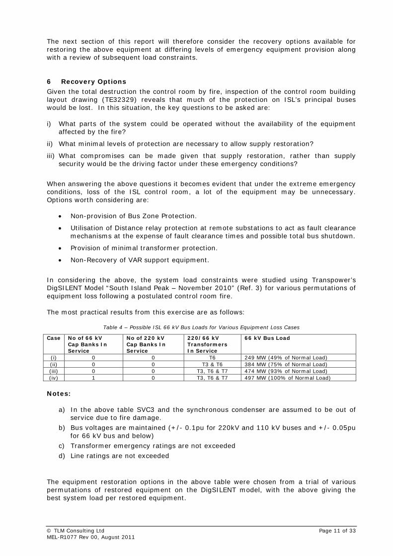
In considering the above, the system load constraints were studied using Transpower’s DigSILENT Model “South Island Peak – November 2010” (Ref. 3) for various permutations of equipment loss following a postulated control room fire. The most practical results from this exercise are as follows:
Table 4 – Possible ISL 66 kV Bus Loads for Various Equipment Loss Cases
Case No of 66 kV Cap Banks In Service
No of 220 kV Cap Banks In Service
220/66 kV Transformers In Service
66 kV Bus Load
(i) 0 0 T6 249 MW (49% of Normal Load) (ii) 0 0 T3 & T6 384 MW (75% of Normal Load) (iii) 0 0 T3, T6 & T7 474 MW (93% of Normal Load) (iv) 1 0 T3, T6 & T7 497 MW (100% of Normal Load)
Notes:
a) In the above table SVC3 and the synchronous condenser are assumed to be out of service due to fire damage.
b) Bus voltages are maintained (+/- 0.1pu for 220kV and 110 kV buses and +/- 0.05pu for 66 kV bus and below)
c) Transformer emergency ratings are not exceeded
d) Line ratings are not exceeded
The equipment restoration options in the above table were chosen from a trial of various permutations of restored equipment on the DigSILENT model, with the above giving the best system load per restored equipment.
© TLM Consulting Ltd Page 11 of 33 MEL-R1077 Rev 00, August 2011
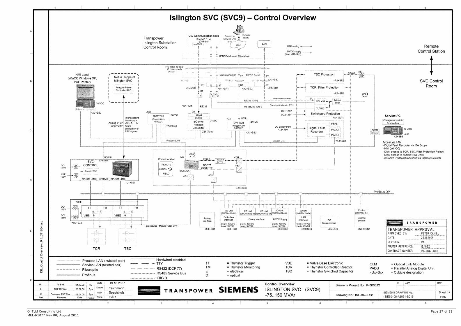
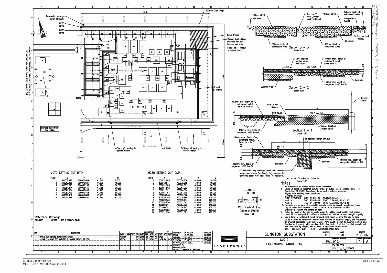
From Table 4, it can be seen that restoring the 220/66 kV transformers should be given the highest priority, followed by at least two of the three 66 kV capacitor banks to achieve normal loading levels. In the above modelling, it has been assumed that SVC9 is available and in service. This assumption was made on the basis that its control equipment is unaffected by the control room fire as its main equipment is located in the SVC control room with only supervisory alarms being sent to the fire affected area. (Refer to drawings E50150-A5031-S015 and TP65615 included in Appendix A) 6.1 33 kV Network
Orion has in the past advised that they would be able to re-configure their distribution network to supply areas of Christchurch normally supplied by the ISL 33 kV bus. For this reason, no attempt has been made to establish an emergency 33 kV supply point as part of this fire recovery plan. 7 Emergency Equipment Requirements
To achieve the levels of power restoration outlined in Table 4, it is necessary to provide replacement equipment for that which would have been destroyed by the control room fire. It would not be practical or cost effective to completely replicate the control room, though with progressively more elaborate equipment provision, load cases (i) through to (iv) could be achieved. From the modelling of the various recovery configurations presented in section 6, it is apparent that getting the 220/66 kV transformers back into service must be a primary objective. On this basis we must consider what minimum levels of protection equipment should be put in place to enable the transformers to operate safely. 7.1 Minimum Transformer Protection
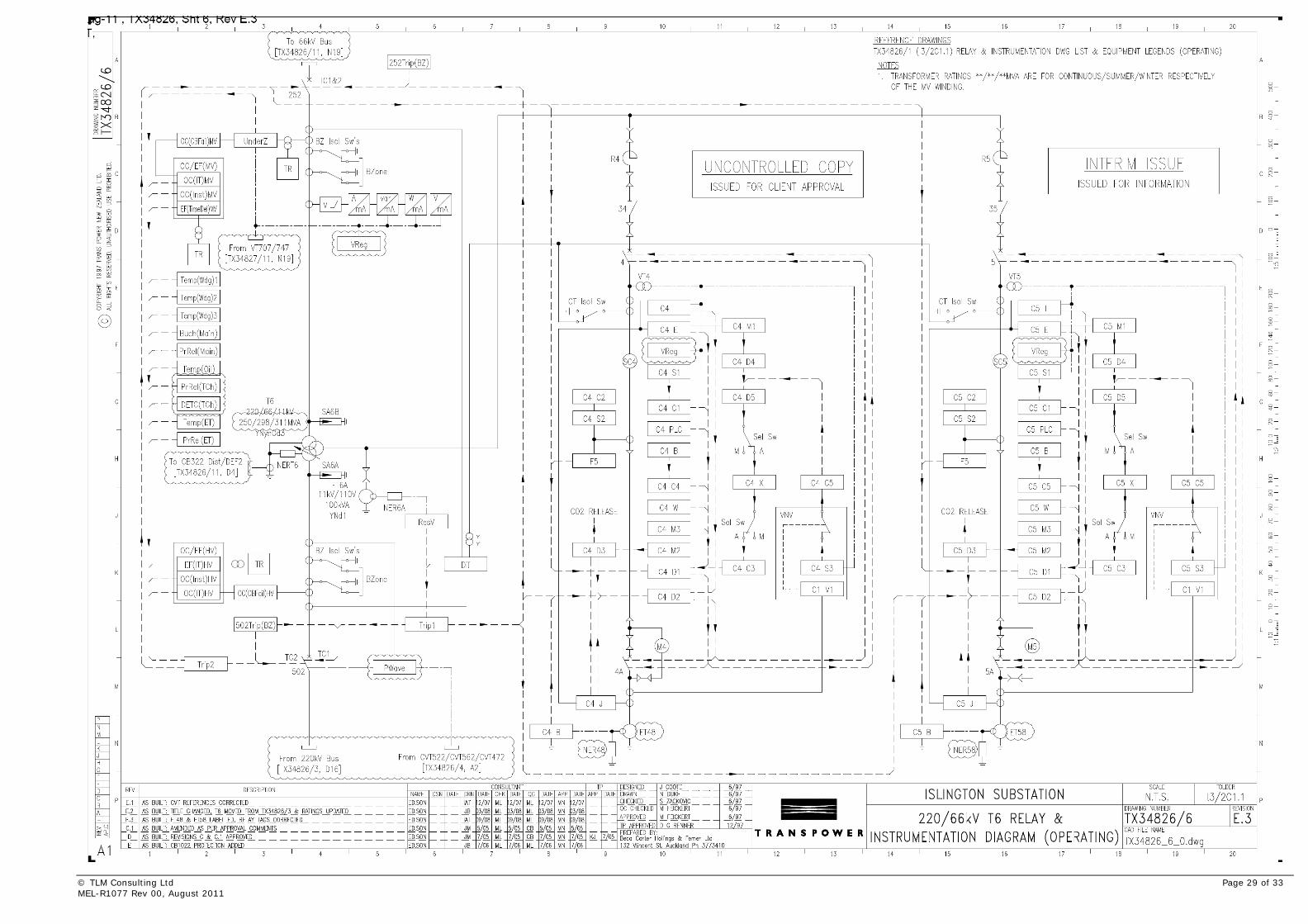
In the emergency conditions envisaged in this report, Transpower may wish to consider placing one or more of the 220/66 kV transformers into service with the absolute minimum of protection equipment. Inspection of drawings TX34826 sheets 6 and 7 reveals typical transformer protection arrangements with: i) Winding Temperature.
ii) Pressure Devices (Bucholz).
iii) Over Current.
iv) Earth Fault.
v) Differential current protection elements.
vi) Voltage Regulation Equipment.
7.1.1 Option 1 – Transformer Built-In Protection Devices Only
From the above list, items (i) and (ii) could be rapidly re-instated by making hardwired connections into the relevant circuit breaker trip circuits along with the provision of a temporary d.c. supply system. With only items (i) and (ii) in place the transformer would be protected against overheating and severe faults. In this situation faults external to the transformer would rely on remote distance protection to be operated. This may be acceptable if the distance protection settings on the incoming 220 kV lines feeding the transformer were reviewed and updated accordingly. The advantages and disadvantages of this option are as follows Advantages – Quick and inexpensive to implement. This would just need cabling and a small d.c. supply battery and charger provision. In the case of a slightly more elaborate provision, Outdoor Junction Boxes (ODJBs) could be constructed to provide a quick patching points for the required cable connection in case the fire emergency condition is ever required
© TLM Consulting Ltd Page 12 of 33 MEL-R1077 Rev 00, August 2011
Disadvantages:
• Internal transformer faults will not be detected as quickly due to the absence of differential protection (Possibly more severe transformer damage before a fault is cleared). Severe faults would still be cleared due to oil level and gas pressure trips initiated by the Bucholz equipment.
• External faults may be slow to clear due to the limitations of using remote distance protection.
• There is no fault discrimination for external faults. An external fault would shut down the HV bus section(s) to which the transformer was connected with a subsequent supply outage.
• No voltage regulation has been provided. Manual Tap adjustment or operation on fixed tap would be necessary.
7.1.2 Option 2 – Option 1 + Provision of transformer protection relays
(Diff, HV & LV OC/EF)
At the expense of more elaborate standby/emergency equipment provisions that would provide all of the functions outlined in paragraph 7.1, it should be possible to provide more robust transformer protection that would reduce the risks to the transformers and would probably allow speedier diagnosis and recovery after a fault condition. Advantages:
• Transformers will be more robustly protected with faster tripping for transformer fault conditions.
• Fault diagnosis and recovery from faults would be quicker due to the additional indications available from the transformer protection relays.
• More options would be available on paralleling the transformers, along with additional bus configurations which would allow the supply system to be more reliable under fault conditions.
• With the provision of dedicated transformer protection equipment, it should be possible to achieve the load levels outlined for case (iii) in Table 4 (83% of normal Load).
• Automatic Voltage Regulation (AVR) equipment could be provided as part of the emergency equipment package.
Disadvantages:
• This will be more expensive to implement due to the additional equipment requirements and provision of outdoor cubicles or ‘Portacom’ style buildings to house the emergency protection equipment cabinets. See Appendix B for details of typical equipment housing arrangements
• There would still be limited fault discrimination for external faults. Though transformer fault diagnosis and restoration times would be better than with option 1.
• The protection system would not be as robust as the normal Transpower standard since it is not expected duplicated protection channels would be provided in order to reduce costs and save space for emergency equipment requirements. Ideally the whole emergency transformer protection suite should fit into one cabinet per transformer.
7.2 Provision of 66 kV Reactive Support The DigSILENT modelling performed for this report revealed that provision of at least one the capacitor banks on the 66 kV bus is vital for achieving full load capability.
© TLM Consulting Ltd Page 13 of 33 MEL-R1077 Rev 00, August 2011
Restoration of the capacitor banks would theoretically be possible without the provision of protection equipment; however there would be risk of damage to the capacitors and possible overvoltages on the system. Also, it may not be possible to operate the capacitor banks without their protection equipment due to the point on wave circuit breaker closure requirements. Based upon consideration of the above, it is thought to be undesirable to operate the 66 kV capacitor banks without some provision of control and protection equipment. Option 3 described below therefore outlines the provision of limited 66 kV reactive support equipment. 7.2.1 Option 3 – Option 2 + Provision of Limited 66 kV Capacitor Bank
Protection The return to service of one of the 66kV capacitor banks would progressively allow full loading to be placed upon the ISL bus allowing near normal levels of load when all three transformers are in service (Though voltage might be slightly low at 0.95 PU). Advantages:
Advantages of option 2 plus:
• The ISL 66 kV bus could be loaded to near normal levels.
Disadvantages: • Slightly more equipment required (1 cubicle per capacitor bank)
• Protection system would not be as robust as the normal Transpower standard since it is not expected duplicated protection channels would be provided in order to reduce costs and save space for emergency equipment requirements. Ideally the whole emergency transformer protection suite should fit into one cabinet per transformer.
7.3 Provision of 220 kV Reactive Support Equipment Since the issue of the previous Islington Disaster Recovery Plan (Ref. 2), an SVC has been commissioned at Kikiwa (KIK) and the availability of this equipment along with ISL’s SVC9 (Not deemed to be affected by a control room fire) helps to support the northern extremities of the South Island 220 kV network and therefore reduces the dependency upon the ISL 220 kV capacitor banks. Emergency recovery of the 220 kV capacitor banks has therefore not been considered in this report.
© TLM Consulting Ltd Page 14 of 33 MEL-R1077 Rev 00, August 2011
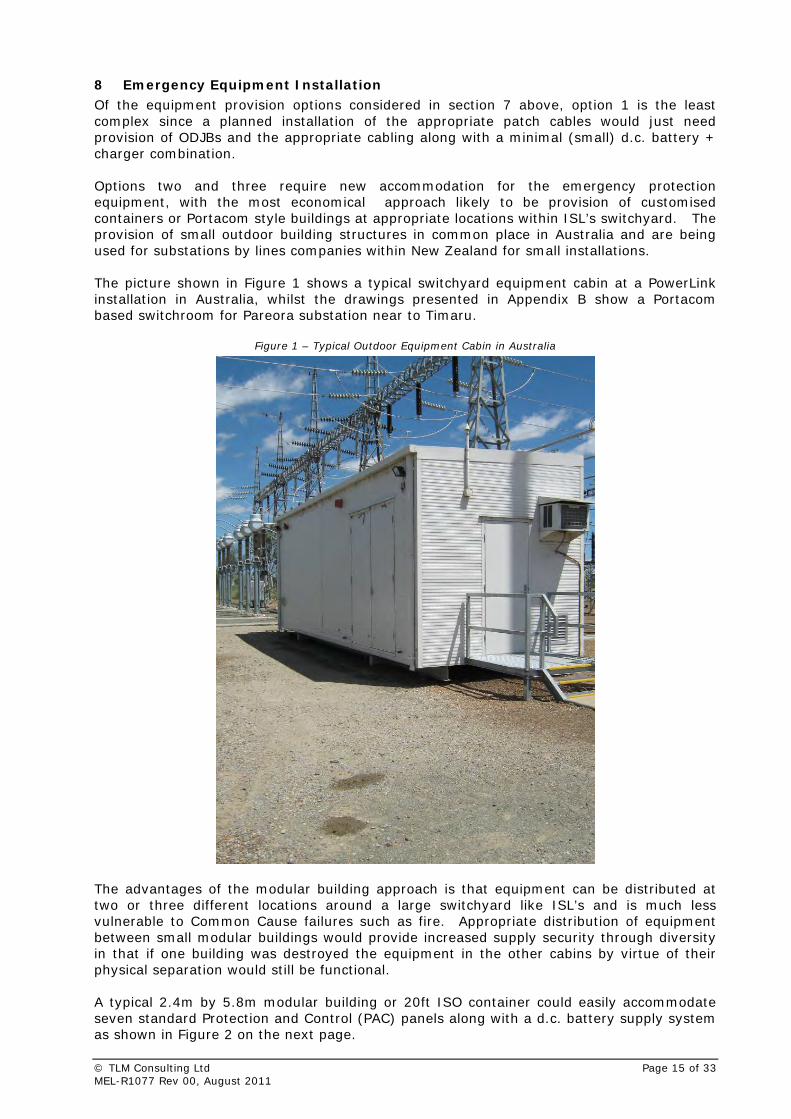
8 Emergency Equipment Installation Of the equipment provision options considered in section 7 above, option 1 is the least complex since a planned installation of the appropriate patch cables would just need provision of ODJBs and the appropriate cabling along with a minimal (small) d.c. battery + charger combination. Options two and three require new accommodation for the emergency protection equipment, with the most economical approach likely to be provision of customised containers or Portacom style buildings at appropriate locations within ISL’s switchyard. The provision of small outdoor building structures in common place in Australia and are being used for substations by lines companies within New Zealand for small installations. The picture shown in Figure 1 shows a typical switchyard equipment cabin at a PowerLink installation in Australia, whilst the drawings presented in Appendix B show a Portacom based switchroom for Pareora substation near to Timaru.
Figure 1 – Typical Outdoor Equipment Cabin in Australia
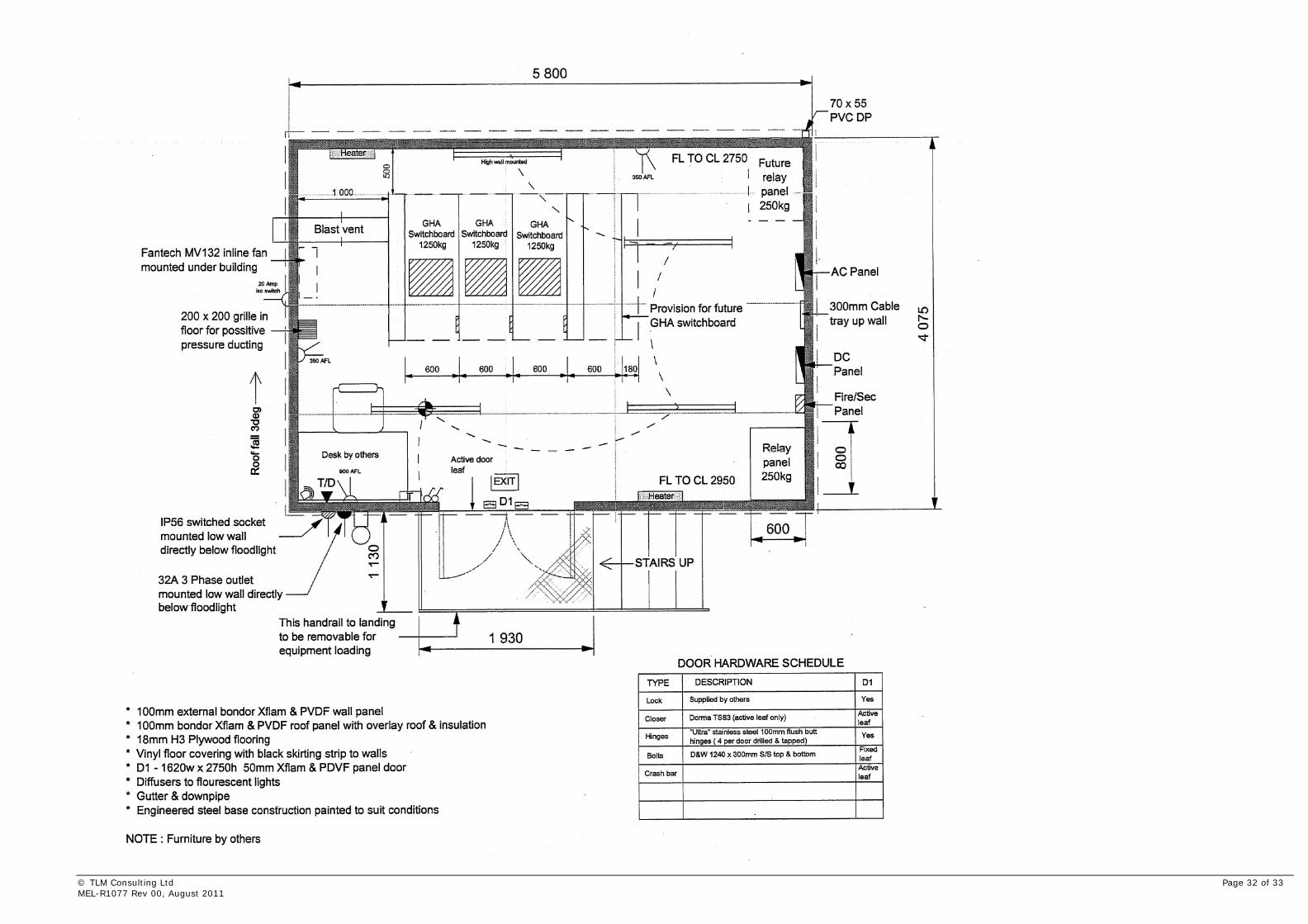
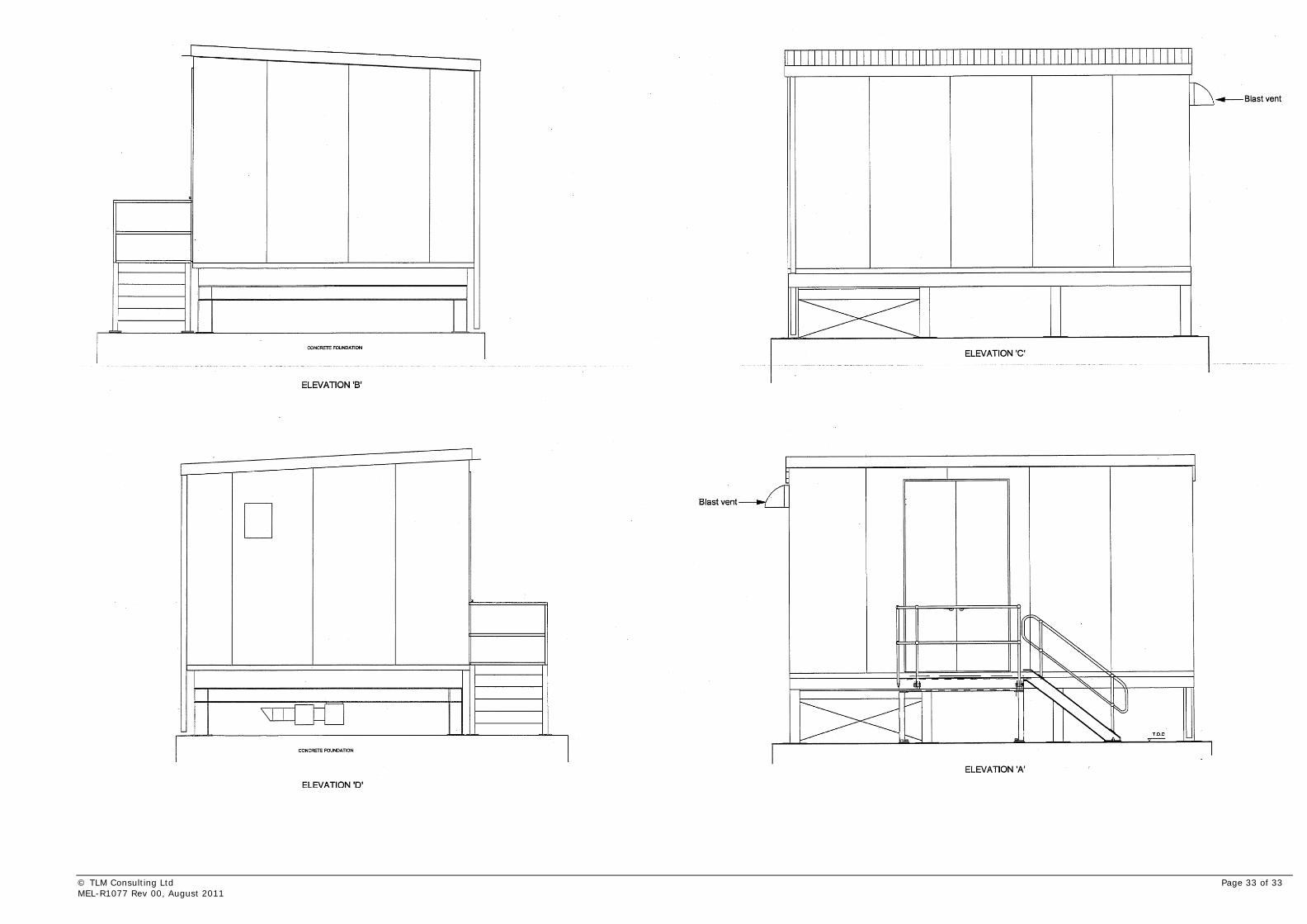
The advantages of the modular building approach is that equipment can be distributed at two or three different locations around a large switchyard like ISL’s and is much less vulnerable to Common Cause failures such as fire. Appropriate distribution of equipment between small modular buildings would provide increased supply security through diversity in that if one building was destroyed the equipment in the other cabins by virtue of their physical separation would still be functional. A typical 2.4m by 5.8m modular building or 20ft ISO container could easily accommodate seven standard Protection and Control (PAC) panels along with a d.c. battery supply system as shown in Figure 2 on the next page.
© TLM Consulting Ltd Page 15 of 33 MEL-R1077 Rev 00, August 2011
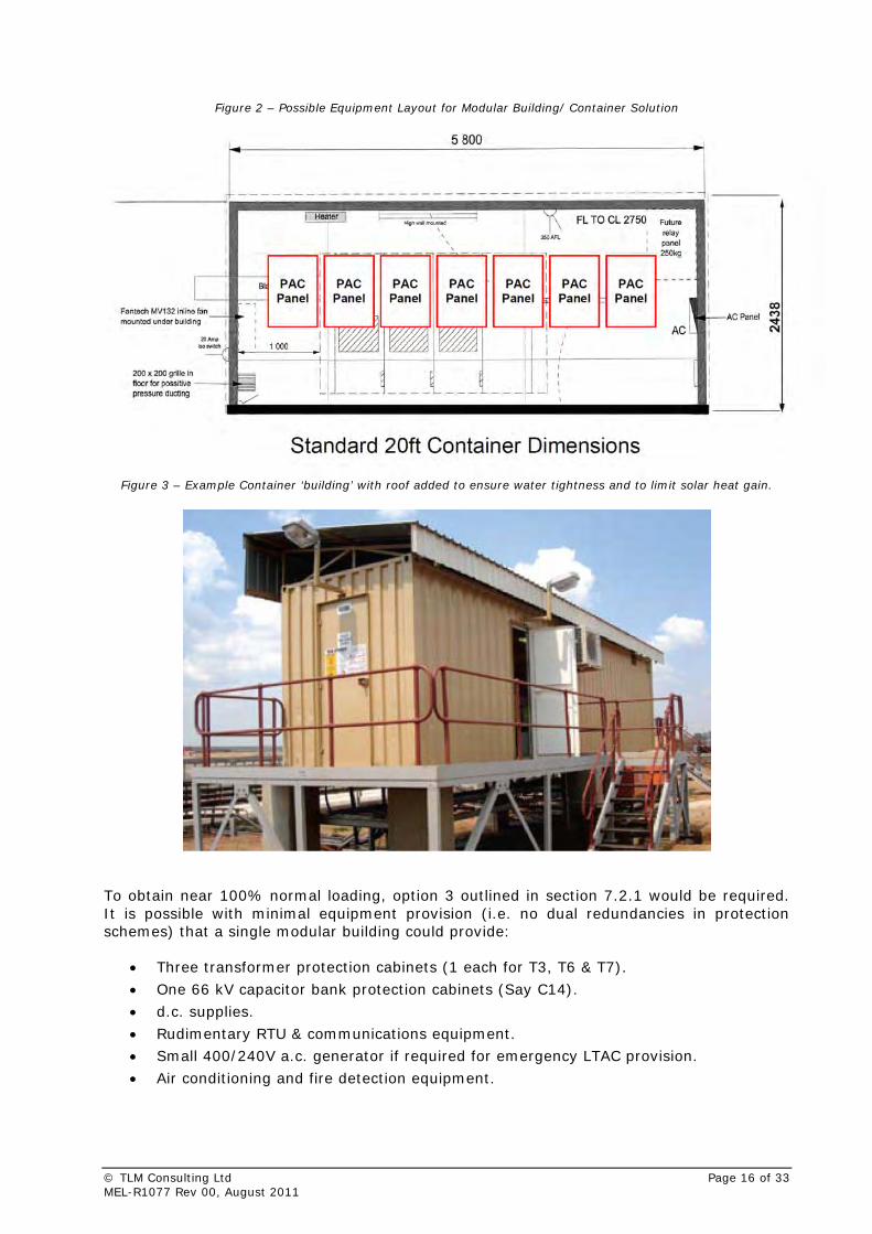
Figure 2 – Possible Equipment Layout for Modular Building/ Container Solution
Figure 3 – Example Container ‘building’ with roof added to ensure water tightness and to limit solar heat gain.
To obtain near 100% normal loading, option 3 outlined in section 7.2.1 would be required. It is possible with minimal equipment provision (i.e. no dual redundancies in protection schemes) that a single modular building could provide:
• Three transformer protection cabinets (1 each for T3, T6 & T7).
• One 66 kV capacitor bank protection cabinets (Say C14).
• d.c. supplies.
• Rudimentary RTU & communications equipment.
• Small 400/240V a.c. generator if required for emergency LTAC provision.
• Air conditioning and fire detection equipment.
© TLM Consulting Ltd Page 16 of 33 MEL-R1077 Rev 00, August 2011
9 Communications Considerations
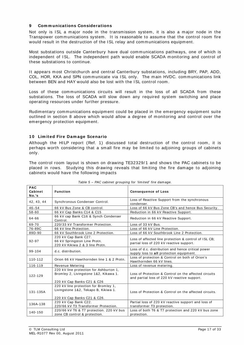
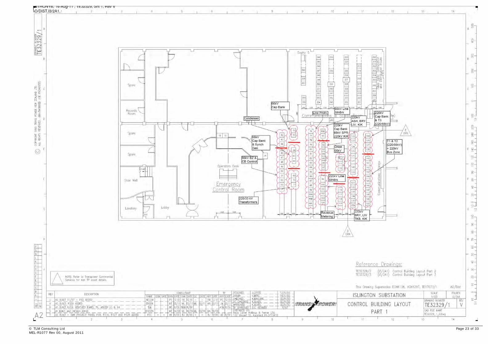
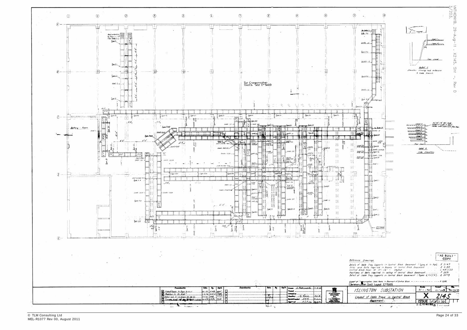
Not only is ISL a major node in the transmission system, it is also a major node in the Transpower communications system. It is reasonable to assume that the control room fire would result in the destruction of the ISL relay and communications equipment. Most substations outside Canterbury have dual communications pathways, one of which is independent of ISL. The independent path would enable SCADA monitoring and control of these substations to continue. It appears most Christchurch and central Canterbury substations, including BRY, PAP, ADD, COL, HOR, KKA and SPN communicate via ISL only. The main HVDC. communications link between BEN and HAY would also be lost with the ISL control room. Loss of these communications circuits will result in the loss of all SCADA from these substations. The loss of SCADA will slow down any required system switching and place operating resources under further pressure. Rudimentary communications equipment could be placed in the emergency equipment suite outlined in section 8 above which would allow a degree of monitoring and control over the emergency protection equipment. 10 Limited Fire Damage Scenario Although the HILP report (Ref. 1) discussed total destruction of the control room, it is perhaps worth considering that a small fire may be limited to adjoining groups of cabinets only. The control room layout is shown on drawing TE32329/1 and shows the PAC cabinets to be placed in rows. Studying this drawing reveals that limiting the fire damage to adjoining cabinets would have the following impacts
Table 5 – PAC cabinet grouping for ‘limited’ fire damage.
PAC Cabinet No.’s
Function Consequence of Loss
42, 43, 44 Synchronous Condenser Control. Loss of Reactive Support from the synchronous condenser.
46–54 66 kV Bus Zone & CB control. Loss of 66 kV Bus Zone CB’s and hence Bus Security. 58-60 66 kV Cap Banks C14 & C15 Reduction in 66 kV Reactive Support.
64-66 66 kV cap Bank C16 & Synch Condenser Control.
Reduction in 66 kV Reactive Support.
69-70 220/33 kV Transformer Protection. Loss of 33 kV Bus. 76-89C 66 kV line Protection. Loss of 66 kV Line Protection. 89D-90 66 kV Southbrook Line 2 Protection. Loss of 66 kV Southbrook Line 2 Protection.
92-97 220 kV Cap Bank C27. 66 kV Springston Line Protn. 220 kV Kikiwa 2 & 3 line Protn.
Loss of affected line protection & control of ISL CB; partial loss of 220 kV reactive support.
99-104 d.c. distribution. Loss of d.c. distribution and hence critical power supply loss to all protection equipment.
110-112 Orion 66 kV Hawthornden line 1 & 2 Protn. Loss of protection & Control on both of Orion’s Hawthornden 66 kV lines.
116-119 Revenue Metering Loss of revenue metering.
122-129
220 kV line protection for Ashburton 1, Bromley 2, Livingstone 1&2, Kikawa 1. 220 kV Cap Banks C21 & C26
Loss of Protection & Control on the affected circuits and partial loss of 220 kV reactive support.
131-135A
220 kV line protection for Bromley 1, Livingstone 1&2, Tekapo B, Kikiwa 1. 220 kV Cap Banks C21 & C26.
Loss of Protection & Control on the affected circuits.
136A-138 220 kV Cap Bank C22. 220/66 kV T3 Transformer Protection.
Partial loss of 220 kV reactive support and loss of transformer T3 protection.
140-150 220/66 kV T6 & T7 protection. 220 kV bus zone CB control & protection.
Loss of both T6 & T7 protection and 220 kV bus zone protection.
© TLM Consulting Ltd Page 17 of 33 MEL-R1077 Rev 00, August 2011
Analysis of the above table reveals that fire damage constrained to adjacent cabinets would limit the consequences when compared with the total destruction scenario. However, the placement of the cabinets is not optimal in that they tend to be grouped by function. This in-turn leads to functional groups of equipment being affected by very small fires and of particular concern is that the d.c. distribution is all in adjacent cabinets which would mean that a small fire could render a complete loss of control and protection equipment due to complete d.c. supply shutdown.
11 Summary The consequences of destruction of the control room equipment fire have been analysed and that recovery from this situation is possible with progressively more load being achieved as more complex solutions are implemented. The quickest ‘fix’ in the absence of dedicated emergency equipment would be to run the 220/66 kV transformers with minimal protection as discussed by option 1 in section 7.1.1. Though bus security would be practically non-existent and voltage regulation would be problematic. To achieve normal bus loadings and to provide higher equipment protection integrity it would be necessary to provide a Portacom style building with a cut-down protection suite as discussed in options 2 and 3 outlined in sections 7 and 8. Although a basic protection suite provision could achieve normal power flows, the ISL buses would be vulnerable to faults due to the lack of dedicated feeder protection and bus zone protection. A single fault could shutdown the entire 220 kV or 66 kV buses. In emergency conditions this may be tolerable, but supply security would be well below Transpower’s normal standards. The level of additional emergency equipment provided to increase bus security would have to be balanced against costs, and further fire mitigation measures etc. 12 Recommendations
Destruction of the control room by fire would have immediately disastrous consequences as outlined in Ref. 2 and section 4 of this report. Loads could eventually be restored to near normal levels using the emergency equipment provisions outlined in this report, though at greatly reduced levels of supply security. Transpower should therefore initially consider employing a suitably qualified fire consultant / engineer in order to quantify likely fire spread scenario for the control room and cable basement ; and to identify cost effective fire mitigation measures. Once the true extent of the fire risk has been quantified and the required fire protection improvements to the control room have been identified, then the level of provision of standby/emergency protection equipment can be set appropriately. In choosing to provide some emergency/standby equipment, it is imperative that a review is undertaken of the performance and possible settings changes to the distance protection equipment at the remote ends of lines connected to ISL. This would confirm the adequacy (or otherwise) of protecting the ISL buses by this means, if the ISL protection cabinets are out of service and help to determine the level of emergency equipment provision required. In the event of a detailed fire report revealing the requirement for extensive modifications to the control room, consideration may be given to the following options:
• Migration of some or all of the control and protection equipment to another building. This should have reduced fire risk and also in the case of partial migration would prevent a fire from shutting down the ISL buses if the equipment was suitably spread across both locations.
© TLM Consulting Ltd Page 18 of 33 MEL-R1077 Rev 00, August 2011
© TLM Consulting Ltd Page 19 of 33 MEL-R1077 Rev 00, August 2011
• Adopt the practice employed by some Australian utilities of having dispersed modular buildings around large switchyards. At ISL a logical arrangement would be to have three such buildings with their own d.c. supplies etc. that nominally supported each of the three 220/66 kV transformer bays plus a share of the reactive support strategically spread through the switchyard.
13 References
1. Islington HILP Study for Transpower New Zealand Ltd, Marsh Consulting 16th June 2011.
2. Islington Substation Disaster Recovery Plan, MEL-R452 Rev01 June 2009 by TLM Consulting Christchurch.
3. Transpower DigSILENT Model “South Island Peak – November 2010”.


Appendix A
Drawings
© TLM Consulting Ltd Page 21 of 33 MEL-R1077 Rev 00, August 2011

© TLM Consulting Ltd Page 22 of 33 MEL-R1077 Rev 00, August 2011
© TLM Consulting Ltd Page 23 of 33 MEL-R1077 Rev 00, August 2011
© TLM Consulting Ltd Page 24 of 33 MEL-R1077 Rev 00, August 2011
© TLM Consulting Ltd Page 25 of 33 MEL-R1077 Rev 00, August 2011
© TLM Consulting Ltd Page 26 of 33 MEL-R1077 Rev 00, August 2011
© TLM Consulting Ltd Page 27 of 33 MEL-R1077 Rev 00, August 2011
© TLM Consulting Ltd Page 28 of 33 MEL-R1077 Rev 00, August 2011
© TLM Consulting Ltd Page 29 of 33 MEL-R1077 Rev 00, August 2011

© TLM Consulting Ltd Page 30 of 33 MEL-R1077 Rev 00, August 2011
Appendix B
Example ‘Modular’ Building Drawings for Substation Equipment
© TLM Consulting Ltd Page 31 of 33 MEL-R1077 Rev 00, August 2011
© TLM Consulting Ltd Page 32 of 33 MEL-R1077 Rev 00, August 2011
© TLM Consulting Ltd Page 33 of 33
MEL-R1077 Rev 00, August 2011