Embed Size (px)
Citation preview


Preface
PrefaceCopyrightThis publication, including all photographs, illustrations and software, is protectedunder international copyright laws, with all rights reserved. Neither this manual, norany of the material contained herein, may be reproduced without written consent ofthe author.
Version 1.0
DisclaimerThe information in this document is subject to change without notice. The manufac-turer makes no representations or warranties with respect to the contents hereof andspecifically disclaims any implied warranties of merchantability or fitness for anyparticular purpose. The manufacturer reserves the right to revise this publication andto make changes from time to time in the content hereof without obligation of themanufacturer to notify any person of such revision or changes.
Federal Communications Commission (FCC)This equipment has been tested and found to comply with the limits for a Class Bdigital device, pursuant to Part 15 of the FCC Rules. These limits are designed toprovide reasonable protection against harmful interference in a residential installa-tion. This equipment generates, uses, and can radiate radio frequency energy and, ifnot installed and used in accordance with the instructions, may cause harmful inter-ference to radio communications. However, there is no guarantee that interferencewill not occur in a particular installation. If this equipment does cause harmfulinterference to radio or television reception, which can be determined by turning theequipment off and on, the user is encouraged to try to correct the interference by oneor more of the following measures:
• Reorient or relocate the receiving antenna• Increase the separation between the equipment and the receiver• Connect the equipment onto an outlet on a circuit different from that to
which the receiver is connected• Consult the dealer or an experienced radio/TV technician for help
Shielded interconnect cables and a shielded AC power cable must be employed withthis equipment to ensure compliance with the pertinent RF emission limits govern-ing this device. Changes or modifications not expressly approved by the system’smanufacturer could void the user’s authority to operate the equipment.
Trademark RecognitionMicrosoft, MS-DOS and Windows are registered trademarks of Microsoft Corp.
MMX, Pentium, Pentium-II, Pentium-III, Celeron are registered trademarks of IntelCorporation.
Other product names used in this manual are the properties of their respectiveowners and are acknowledged.
ii
Preface
Declaration of ConformityThis device complies with part 15 of the FCC rules. Operation is subject to thefollowing conditions:
• This device may not cause harmful interference, and• This device must accept any interference received, including interfer-
ence that may cause undesired operation
Canadian Department of CommunicationsThis class B digital apparatus meets all requirements of the Canadian Interference-causing Equipment Regulations.
Cet appareil numérique de la classe B respecte toutes les exigences du Réglement surle matériel brouilieur du Canada.
About the ManualThe manual consists of the following:
Describes features of themotherboard.
Go to page 1
Describes installation ofmotherboard components.
Go to page 7
Provides information on us-ing the BIOS Setup Utility.
Go to page 25
Describes the motherboardsoftwareGo to page 43
Chapter 1
Introducing the Motherboard
Chapter 2
Installing the Motherboard
Chapter 3
Using BIOS
Chapter 4
Using the Motherboard Software
Describes the ATICrossfireXTM Technology
Go to page 49
Chapter 5
ATI CrossfireXTM Technology Support
Describes the Intel® MatrixStorage Manager RAID Con-figurationsGo to page 53
Chapter 6Intel® Matrix Storage ManagerRAID Configurations
iii
TTTTTABLE OF CONTENTSABLE OF CONTENTSABLE OF CONTENTSABLE OF CONTENTSABLE OF CONTENTSPreface i
Chapter 1 1Introducing the Motherboard 1
Introduction......................................................................................1Feature ..............................................................................................2Specifications...................................................................................4Motherboard Components.............................................................5
Chapter 2 7 7 7 7 7Installing the Motherboard 7
Safety Precautions...........................................................................7Choosing a Computer Case............................................................7Installing the Motherboard in a Case...........................................7Checking Jumper Settings..............................................................8
Setting Jumpers........................................................................8Checking Jumper Settings........................................................9Jumper Settings........................................................................9
Installing Hardware..................................................................10Installing the Processor..........................................................10Installing Memory Modules....................................................12Expansion Slots......................................................................15Connecting Optional Devices.................................................17
Installing a Hard Disk Drive/CD-ROM/SATA Hard Drive....19Installing a Floppy Diskette Drive.........................................20
Connecting I/O Devices................................................................21Connecting Case Components....................................................22
Front Panel Header................................................................24
Chapter 3 25Using BIOS 25
About the Setup Utility................................................................ 25The Standard Configuration...................................................25Entering the Setup Utility........................................................25
Using BIOS.....................................................................................26Standard CMOS Setup...........................................................27Advanced Setup......................................................................29Advanced Chipset Setup.........................................................32
iv
Integrated Peripherals.......................................................33Power Management Setup.................................................34PCI/PnP Configuration......................................................35PC Health Status................................................................36M.I.B. (MB Intelligent BIOS).............................................38Load Default Settings.......................................................40Supervisor Password........................................................40User Password..................................................................41Save & Exit Setup...............................................................41Exit Without Saving............................................................41Updating the BIOS.............................................................42
Chapter 4 43 43 43 43 43Using the Motherboard Software 43
About the Software CD-ROM......................................................43Auto-installing under Windows XP/Vista..................................43
Running Setup....................................................................44Manual Installation........................................................................48Utility Software Reference............................................................48
Chapter 5 49 49 49 49 49ATI CrossFireX™ Technology Support 49
Requirements..................................................................................49Installing a single graphics card..................................................49Installing CrossFireX™ graphics cards.......................................50The Catalyst™ Control Center Dialog Box..................................52
View....................................................................................52To Enable CrossFireX™......................................................52
Chapter 6 53 53 53 53 53Intel® Matrix Storage Manager RAID Configurations 53
Before creating a RAID set...........................................................53Entering Intel® Matrix Storage Manager RAID BIOS utility...54Creating a RAID set.......................................................................55Deleting a RAID set.......................................................................57Resetting disks to Non-RAID......................................................58Exiting Setup...................................................................................58
1
Introducing the Motherboard
Chapter 1Introducing the Motherboard
Introduction
Thank you for choosing the P45T-AD3 motherboard. This motherboard is a highperformance, enhanced function motherboard designed to support the LGA775 socketIntel® Yorkfield/Wolfdale/CoreTM 2 Extreme processors for high-end business or per-sonal desktop markets.
There is an advanced full set of I/O ports in the rear panel, including PS/2 mouse andkeyboard connectors, one serial port, one ESATA port, six USB ports, one LAN portand audio jacks for microphone, line-in and 8-ch line-out.
The ICH10R Southbridge supports two PCI slots which are PCI v2.3 compliant. Itimplements an EHCI compliant interface that provides 480 Mb/s bandwidth fortwelve USB 2.0 ports (six USB ports and three USB 2.0 headers support additional sixUSB ports). One onboard IDE connector supports two IDE devices in Ultra ATA 133/100/66/33 mode. The Southbridge supports six SATA ports with maximum transferrate up to 3.0 Gb/s each. It supports Intel® Matrix Storage Technology, providingboth AHCI and RAID 0, 1, 5 and 10 configuration.
The motherboard incorporates the Intel Eaglelake P45 Northbridge (NB) and IntelICH10R Southbridge (SB) chipsets. The Northbridge supports a Front Side Bus (FSB)frequency of 1600(overclocking)/1333/1066 MHz using a scalable FSB Vcc_CPU.The memory controller supports DDR3 memory DIMM frequencies of1600(overclocking)/1333/1066/800. It supports four DDR3 sockets with maximummemory size of 8 GB. High resolution graphics via two PCI Express x16 slots,intended for Graphics Interface, are fully compliant to the PCI Express Base Speci-fication Revision 2.0. It supports the ATI CrossFireXTM Technology that allows youto install GPU graphics cards.

2
Introducing the Motherboard
FeatureProcessorThis motherboard uses an LGA775 type of Intel® Yorkfield/Wolfdale/CoreTM 2Extreme that carries the following features:
• Accommodates Intel® Yorkfield/Wolfdale/CoreTM 2 Extreme processors• Supports a system bus (FSB) of 1600(overclocking)/1333/1066 MHz
Chipset
• Supports DDR3 1600(overclocking)/1333/1066/800 DDR3 SDRAM withDual-channel architecture
• Accommodates four unbuffered DIMMs• Up to 2 GB per DIMM with maximum memory size up to 8 GB
Memory
Audio• RealTek ALC883 7.1ch High Definition audio CODEC
The P45 Northbridge (NB) and ICH10R Southbridge (SB) chipsets are based on aninnovative and scalable architecture with proven reliability and performance.P45 (NB) • Supports 36-bit host bus addressing, allowing the
CPU to access the entire 64 GB of the memory ad-dress space
• 2 GB/s point-to-point Direct Media Interface (DMI) toICH10 (1 GB/s each direction)
• Two PCI Express x16 slots, intended for GraphicsInterface, are fully compliant to the PCI Express BaseSpecification Revision 2.0
• Supports 512-Mb and 1-Gb DDR2 and 512-Mb, 1-Gb,and 2-Gb DDR3 DRAM technologies for x8 and x16devices
ICH10R (SB) • Enhanced DMA Controller, interrupt controller, and timerfunctions
• Compliant with PCI Express Base Specification, revi-sion 1.1
• Compliant with PCI v2.3 specification• Compliant with SATA 3.0 Gb/s Host Controller• Integrated USB 2.0 Host Controller supporting up to
twelve USB 2.0 ports• Supports Intel® Matrix Storage Technology, providing
both AHCI and RAID 0, 1, 5 and 10 configuration
Onboard LAN• Gigabit LAN, Athlos L1 PCIe GigaLAN controller
3
Introducing the Motherboard
This motherboard supports Ultra DMA bus mastering with transfer rates of 133/100/66/33 Mb/s.
• Two PCI Express x16 slots for Graphics Interface• Two PCI Express x1 slots• Two 32-bit PCI v2.3 compliant slots• One IDE connector supporting up to two IDE devices• One floppy disk drive interface• Six 7-pin SATA connectors
Expansion Options
Integrated I/O
The motherboard comes with the following expansion options:
• Two PS/2 ports for mouse and keyboard• One Serial port• One ESATA port• Six USB ports• One LAN port• Audio jacks for microphone, line-in and 8-ch line-out
BIOS Firmware
• Power management• Wake-up alarms• CPU parameters• CPU and memory timing• ECS M.I.B. BIOS
1. Some hardware specifications and software items are subject to changewithout prior notice.
The motherboard has a full set of I/O ports and connectors:
The motherboard uses AMI BIOS that enables users to configure many systemfeatures including the following:
The firmware can also be used to set parameters for different processor clockspeeds.
2. Due to chipset limitation, we recommend that motherboard be oper-ated in the ambiance between 0 and 50 ° C.
4
Introducing the Motherboard
• Intel Eaglelake P45 & ICH10R• North Bridge: Intel Eaglelake P45• South Bridge: Intel ICH10R
• LGA775 socket for Intel® Yorkfield/Wolfdale/CoreTM 2 Ex-treme processors
• FSB 1600(overclocking)/1333/1066 MHz
• Dual-channel DDR3 memory architecture• 4 x 240-pin DDR3 DIMM socket support up to 8 GB• Supports DDR3 1600(overclocking)/1333/1066/800 DDR3
SDRAM• 2 x PCI Express x16 slots• 2 x PCI Express x1 slots• 2 x PCI slots• Support by Intel ICH10R• 6 x Serial ATAII devices• Supports RAID0, 1, 5, 10• Support by JMicron® JMB361• 2 x Ultra DMA 133/100/66 device• 1 x ESATAII 3.0 Gb/s device
• RealTek ALC883 7.1ch High Definition audio CODEC• Gigabit LAN, Athlos L1 PCIE GigaLAN controller
• 1 x PS/2 keyboard & PS/2 mouse connectors• 6 x USB ports• 1 x ESATA port• 1 x COM port• 1 x RJ 45 LAN connector• 1 x Audio port• 1 x 24-pin ATX Power Supply connector & 8-pin 12V con-
nector• 1 x IDE connector• 6 x Serial ATA connectors• 3 x USB 2.0 headers support additional 6 USB ports• 1 x Clear CMOS button• 1 x Front panel header• 1 x Front panel audio header• 1 x CD_in header• CPUFAN/SYSFAN connectors• 1 x Reset button• 1 x Power on button
Chipset
Memory
ExpansionSlots
Storage
AudioLAN
Rear Panel I/O
Internal I/OConnectors &Headers
• AMI BIOS with 8Mb SPI ROM• Supports Plug and Play, STR/STD, Hardware monitor, PCI
interrupt selection, ACPI & DMI, CPU FSB adjustment (in-crease of 1MHz)
• Supports ACPI revision 1.0 specification
System BIOS
Form Factor • ATX Size, 305mm x 244mm
CPU
Specifications
5
Introducing the Motherboard
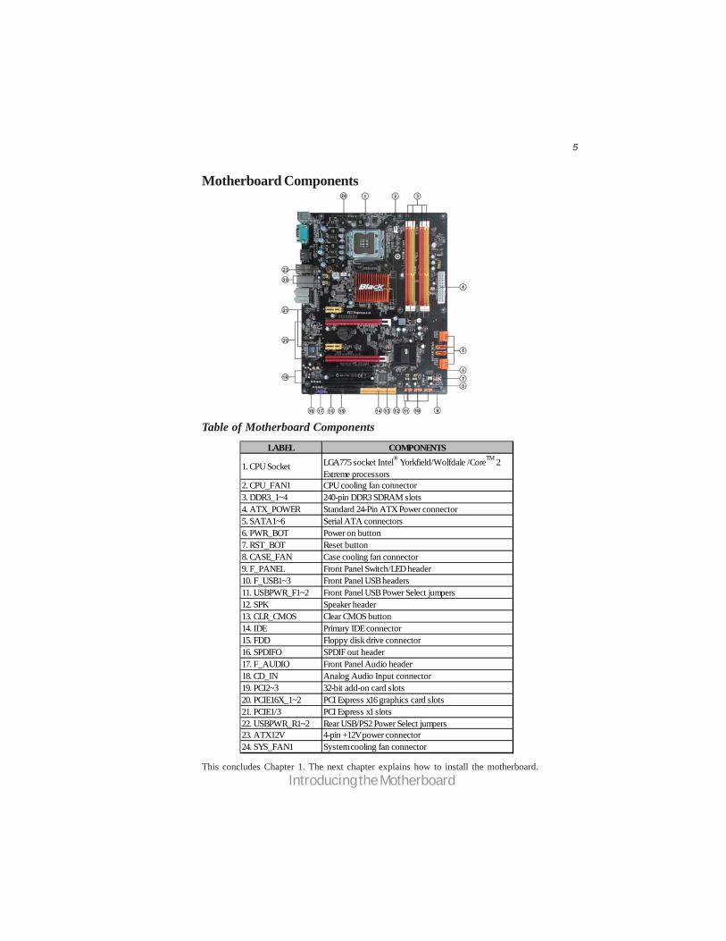
Table of Motherboard Components
This concludes Chapter 1. The next chapter explains how to install the motherboard.
Motherboard Components
LABEL COMPONENTS
1. CPU Socket LGA775 socket Intel® Yorkfield/Wolfdale /CoreTM 2Extreme processors
2. CPU_FAN1 CPU cooling fan connector3. DDR3_1~4 240-pin DDR3 SDRAM slots4. ATX_POWER Standard 24-Pin ATX Power connector5. SATA1~6 Serial ATA connectors6. PWR_BOT Power on button7. RST_BOT Reset button8. CASE_FAN Case cooling fan connector9. F_PANEL Front Panel Switch/LED header10. F_USB1~3 Front Panel USB headers11. USBPWR_F1~2 Front Panel USB Power Select jumpers12. SPK Speaker header13. CLR_CMOS Clear CMOS button14. IDE Primary IDE connector15. FDD Floppy disk drive connector16. SPDIFO SPDIF out header17. F_AUDIO Front Panel Audio header18. CD_IN Analog Audio Input connector19. PCI2~3 32-bit add-on card slots20. PCIE16X_1~2 PCI Express x16 graphics card slots21. PCIE1/3 PCI Express x1 slots22. USBPWR_R1~2 Rear USB/PS2 Power Select jumpers23. ATX12V 4-pin +12V power connector24. SYS_FAN1 System cooling fan connector

6
Introducing the Motherboard
Memo
7
Installing the Motherboard
Chapter 2Installing the Motherboard
Safety Precautions• Follow these safety precautions when installing the motherboard• Wear a grounding strap attached to a grounded device to avoid dam-
age from static electricity• Discharge static electricity by touching the metal case of a safely
grounded object before working on the motherboard• Leave components in the static-proof bags they came in• Hold all circuit boards by the edges. Do not bend circuit boards
Choosing a Computer CaseThere are many types of computer cases on the market. The motherboard complieswith the specifications for the ATX system case. Firstly, some features on themotherboard are implemented by cabling connectors on the motherboard to indica-tors and switches on the system case. Make sure that your case supports all thefeatures required. Secondly, this motherboard supports one floppy diskette drive andtwo enhanced IDE drives. Make sure that your case has sufficient power and space forall drives that you intend to install.
Most cases have a choice of I/O templates in the rear panel. Make sure that the I/Otemplate in the case matches the I/O ports installed on the rear edge of themotherboard.
This motherboard carries an ATX form factor of 305 x 244 mm. Choose a case thataccommodates this form factor.
Installing the Motherboard in a CaseRefer to the following illustration and instructions for installing the motherboard ina case.
Most system cases have mounting brackets installed in the case, which correspondthe holes in the motherboard. Place the motherboard over the mounting bracketsand secure the motherboard onto the mounting brackets with screws.
Ensure that your case has an I/O template that supports the I/O ports and expansionslots on your motherboard.
8
Installing the Motherboard
Checking Jumper SettingsThis section explains how to set jumpers for correct configuration of the motherboard.
Setting JumpersUse the motherboard jumpers to set system configuration options. Jumpers withmore than one pin are numbered. When setting the jumpers, ensure that the jumpercaps are placed on the correct pins.
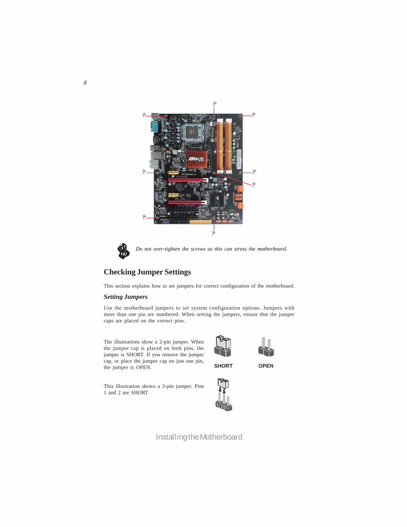
The illustrations show a 2-pin jumper. Whenthe jumper cap is placed on both pins, thejumper is SHORT. If you remove the jumpercap, or place the jumper cap on just one pin,the jumper is OPEN.
This illustration shows a 3-pin jumper. Pins1 and 2 are SHORT
SHORT OPEN
Do not over-tighten the screws as this can stress the motherboard.
9
Installing the Motherboard
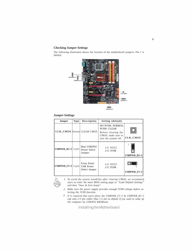
Checking Jumper SettingsThe following illustration shows the location of the motherboard jumpers. Pin 1 islabeled.
To avoid the system instability after clearing CMOS, we recommendusers to enter the main BIOS setting page to “Load Default Settings”and then “Save & Exit Setup”.
1.
2. Make sure the power supply provides enough 5VSB voltage before se-lecting the 5VSB function.
3. It is required that users place the USBPWR_F1~2 & USBPWR_R1~2cap onto 2-3 pin rather than 1-2 pin as default if you want to wake upthe computer by USB/PS2 KB/Mouse.
Jumper Settings
Jumper Type Description Setting (default)
CLR_CMOS button CLEAR CMOS
NO PUSH: NORMALPUSH: CLEARBefore clearing theCMOS, make sure toturn the system off.
3-pinUSBPWR_R1~2 1-2: VCC52-3: 5VSB
Rear USB/PS2Power SelectJumper
3-pinUSBPWR_F1~21-2: VCC52-3: 5VSB
Front PanelUSB PowerSelect Jumper
USBPWR_F1~2
CLR_CMOS
USBPWR_R1~2
1
1
10
Installing the Motherboard
Installing HardwareInstalling the Processor
Caution: When installing a CPU heatsink and cooling fan make sure thatyou DO NOT scratch the motherboard or any of the surface-mount resis-tors with the clip of the cooling fan. If the clip of the cooling fan scrapesacross the motherboard, you may cause serious damage to the motherboardor its components.
This motherboard has an LGA775 socket. When choosing a processor, consider theperformance requirements of the system. Performance is based on the processordesign, the clock speed and system bus frequency of the processor, and the quantityof internal cache memory and external cache memory.
Before installing the Processor
This motherboard automatically determines the CPU clock frequency and system busfrequency for the processor. You may be able to change the settings in the systemSetup Utility. We strongly recommend that you do not over-clock processors orother components to run faster than their rated speed.
On most motherboards, there are small surface-mount resistors near theprocessor socket, which may be damaged if the cooling fan is carelesslyinstalled.
Avoid using cooling fans with sharp edges on the fan casing and the clips.Also, install the cooling fan in a well-lit work area so that you can clearlysee the motherboard and processor socket.
Warning:
1. Over-clocking components can adversely affect the reliability of thesystem and introduce errors into your system. Over-clocking can perma-nently damage the motherboard by generating excess heat in componentsthat are run beyond the rated limits.
2. Always remove the AC power by unplugging the power cord from thepower outlet before installing or removing the motherboard or otherhardware components.
11
Installing the Motherboard
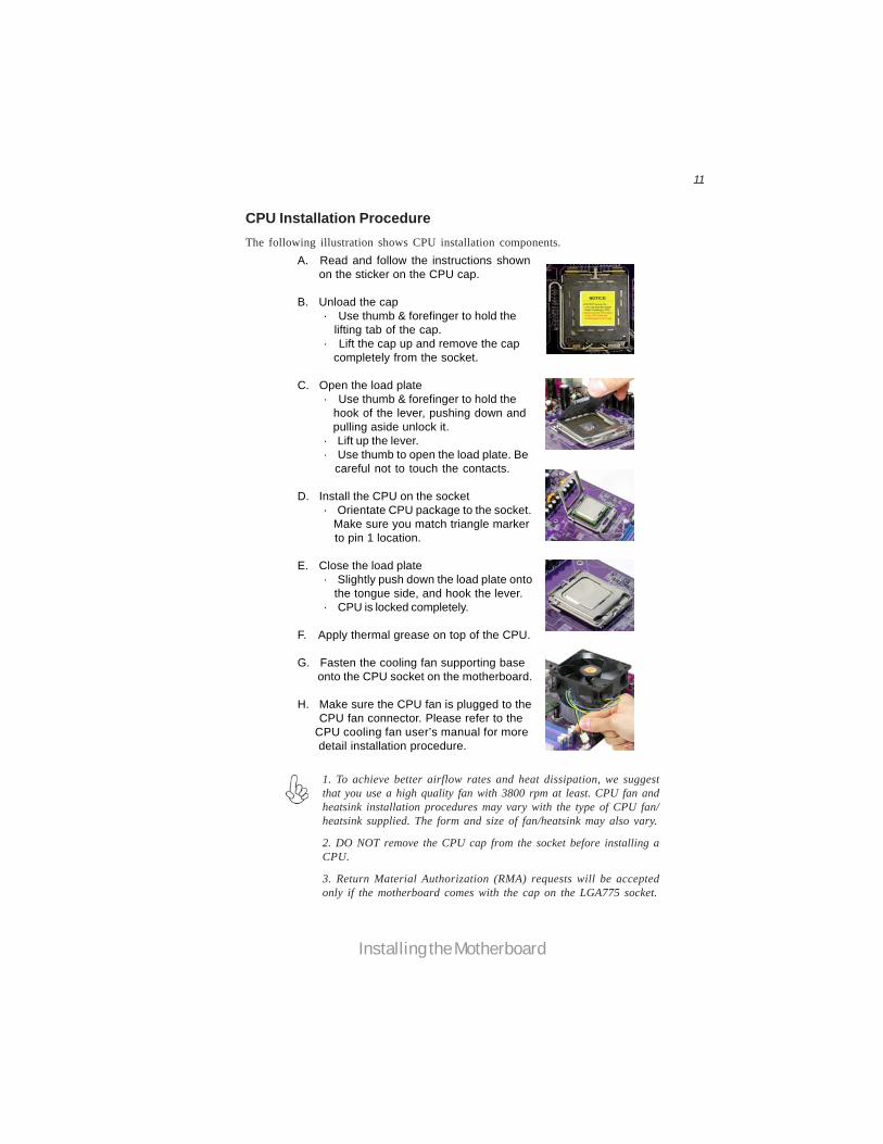
A. Read and follow the instructions shown on the sticker on the CPU cap.
B. Unload the cap· Use thumb & forefinger to hold the lifting tab of the cap.· Lift the cap up and remove the cap completely from the socket.
C. Open the load plate· Use thumb & forefinger to hold the hook of the lever, pushing down and pulling aside unlock it.· Lift up the lever.· Use thumb to open the load plate. Be careful not to touch the contacts.
D. Install the CPU on the socket· Orientate CPU package to the socket. Make sure you match triangle marker to pin 1 location.
E. Close the load plate· Slightly push down the load plate onto the tongue side, and hook the lever.· CPU is locked completely.
F. Apply thermal grease on top of the CPU.
G. Fasten the cooling fan supporting base onto the CPU socket on the motherboard.
H. Make sure the CPU fan is plugged to the CPU fan connector. Please refer to the CPU cooling fan user’s manual for more detail installation procedure.
CPU Installation ProcedureThe following illustration shows CPU installation components.
1. To achieve better airflow rates and heat dissipation, we suggestthat you use a high quality fan with 3800 rpm at least. CPU fan andheatsink installation procedures may vary with the type of CPU fan/heatsink supplied. The form and size of fan/heatsink may also vary.
2. DO NOT remove the CPU cap from the socket before installing aCPU.
3. Return Material Authorization (RMA) requests will be acceptedonly if the motherboard comes with the cap on the LGA775 socket.

12
Installing the Motherboard
Installing Memory ModulesThis motherboard accommodates four memory modules. It can support four 240-pinDDR3 1600(overclocking)/1333/1066/800. The total memory capacity is 8 GB.
DDR3 SDRAM memory module table
You must install at least one module in any of the four slots. Each module can beinstalled with 2 GB of memory; total memory capacity is 8 GB.
Memory module Memory Bus
DDR3 1066 533 MHz DDR3 1333 667 MHz
DDR3 800 400 MHz
Installation ProcedureRefer to the following to install the memory modules.
1 This motherboard supports unbuffered DDR3 SDRAM only.2 Push the latches on each side of the DIMM slot down.3 Align the memory module with the slot. The DIMM slots are keyed with
notches and the DIMMs are keyed with cutouts so that they can only beinstalled correctly.
4 Check that the cutouts on the DIMM module edge connector match thenotches in the DIMM slot.
5 Install the DIMM module into the slot and press it firmly down until itseats correctly. The slot latches are levered upwards and latch on tothe edges of the DIMM.
6 Install any remaining DIMM modules.
Do not remove any memory module from its antistatic packaging untilyou are ready to install it on the motherboard. Handle the modules onlyby their edges. Do not touch the components or metal parts. Alwayswear a grounding strap when you handle the modules.
DDR3 1600 800 MHz
Channel 0: DDR3_1, DDR3_2
Channel 1: DDR3_3, DDR4_4
The four DDR3 memory sockets (DDR3_1, DDR3_2, DDR3_3, DDR3_4) are di-vided into two channels and each channel has two memory sockets as following:
13
Installing the Motherboard
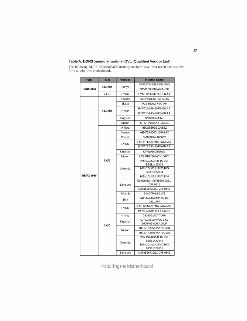
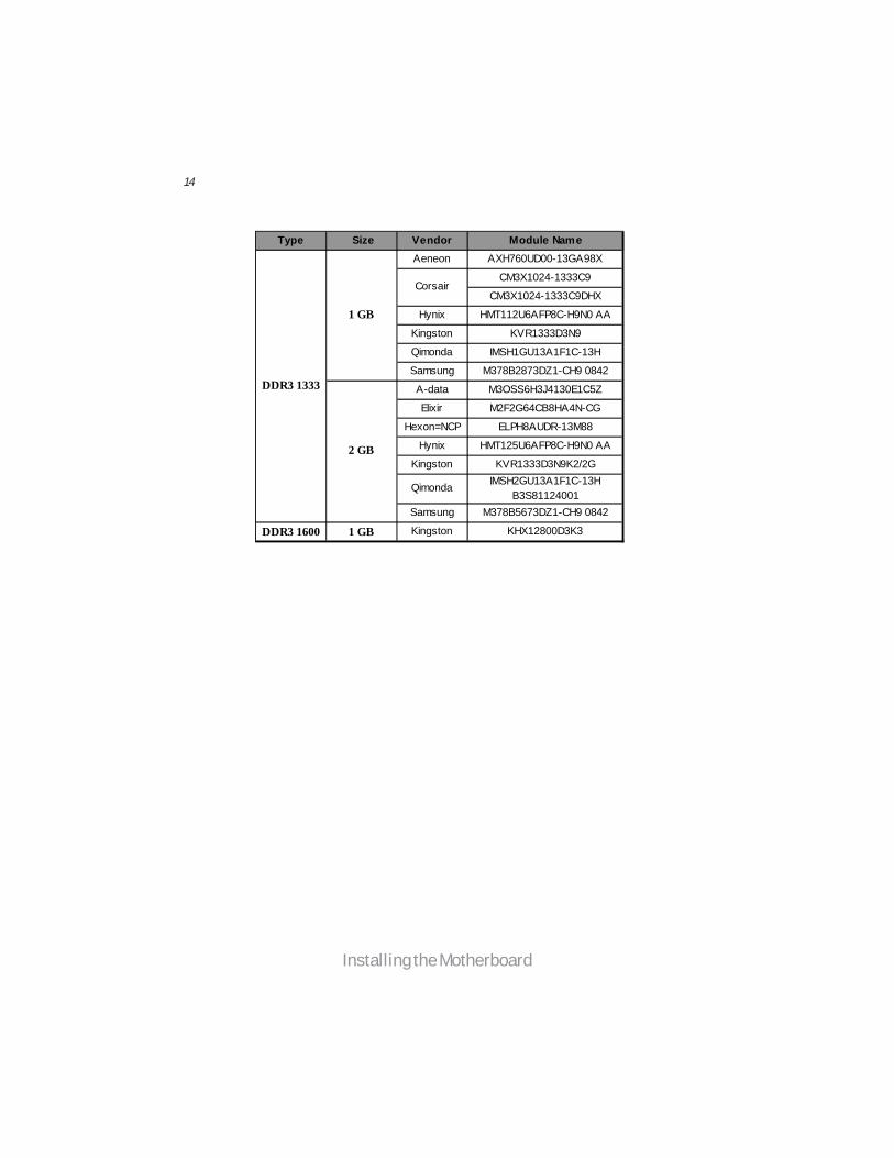
Table A: DDR3 (memory module) QVL (Qualified Vendor List)The following DDR3 1333/1066/800 memory modules have been tested and qualifiedfor use with this motherboard.
Type Size Vendor Module NameNT512C64B88A0NY-25D
NT512C64B88A0NY-BF
2 GB HYNIX HYMT125U64ZNF8-S6 AA
Aeneon AEH760UD00-10FA98X
Elpida PC3-8500U-7-00-AP
HYMT164U64ZNF6-G8 AA
HYMT164U64ZNF8-G8 AA
Kingston KVR1066D3N7
Micron MT4JTF6464AY-1G1B1
A-data M3OSS3H3I3120B5Z
Aeneon AEH760UD00-10FA98X
Corsair CM3X1024-1066C7
HMT112U6AFP8C-G7N0 AAHYMT112U64ZNF8-G8 AA
Kingston KVR1066D3N7/1G
Micron MT8JTF12864AY-1G1D1IMSH1GU03A1F1C-10F
B2S81427023IMSH1GU03A1F1C-10G
B2S81427034IMSH1GU13A1F1C-13H
Golden Bar M378B2873DZ1-CF8 0818
M378B2873DZ1-CF8 0842
Winchip 64A0TPHN8G17E
Elixir M2F2G64CB8HA4N-BE0831.TW
HMT125U6AFP8C-G7N0 AA
HYMT125U64ZNF8-G8 AA
Infinity 04092G16DY7U4A
Kingston KVR1066D3N7/2G 1.5V9905403-006.A00LF
MT16JTF25664AY-1G1D1
MT18JTF25664AY-1G1D1IMSH2GU13A1F1C-10F
B3S81427044IMSH2GU13A1F1C-10G
B3S81528005Samsung M378B5673DZ1-CF8 0842
Micron
DDR3 800512 MB Nanya
Qimonda
DDR3 1066
512 MB HYNIX
1 GB
HYNIX
Qimonda
Samsung
2 GB
HYNIX
14
Installing the Motherboard
Type Size Vendor Module NameAeneon AXH760UD00-13GA98X
CM3X1024-1333C9
CM3X1024-1333C9DHX
Hynix HMT112U6AFP8C-H9N0 AA
Kingston KVR1333D3N9
Qimonda IMSH1GU13A1F1C-13H
Samsung M378B2873DZ1-CH9 0842
A-data M3OSS6H3J4130E1C5Z
Elixir M2F2G64CB8HA4N-CG
Hexon=NCP ELPH8AUDR-13M88
Hynix HMT125U6AFP8C-H9N0 AA
Kingston KVR1333D3N9K2/2G
Qimonda IMSH2GU13A1F1C-13HB3S81124001
Samsung M378B5673DZ1-CH9 0842
DDR3 1600 1 GB Kingston KHX12800D3K3
DDR3 1333
1 GB
Corsair
2 GB
15
Installing the Motherboard
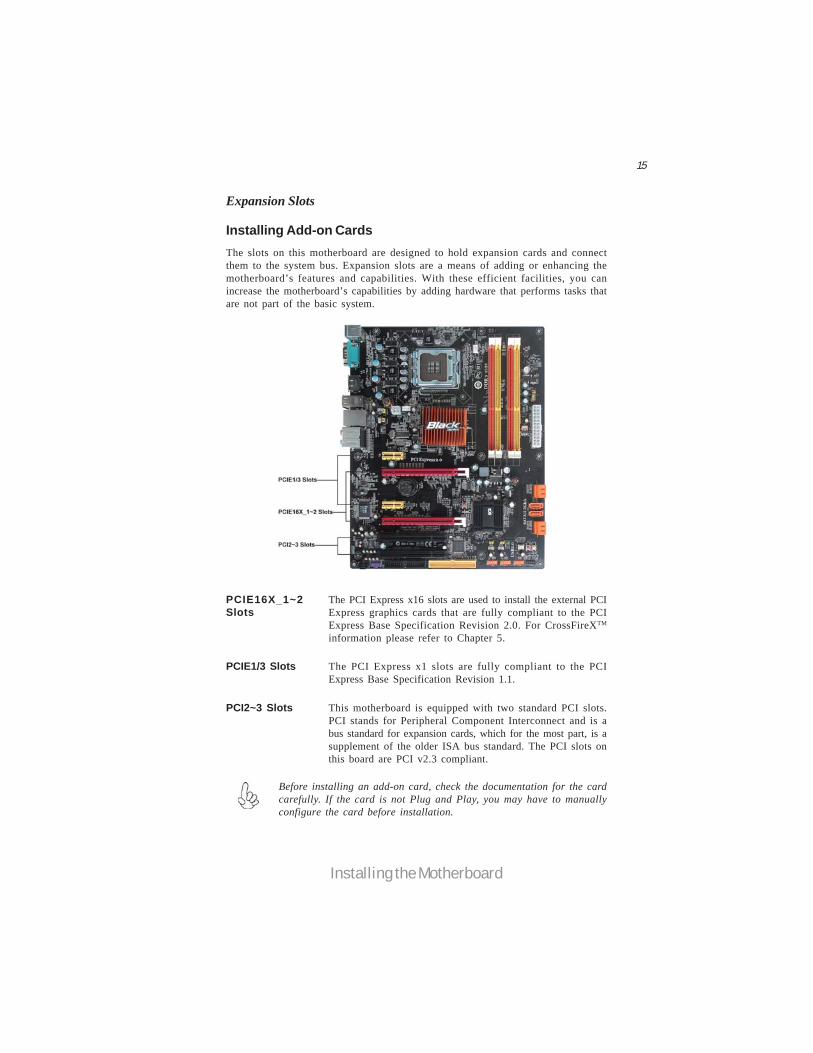
Installing Add-on CardsThe slots on this motherboard are designed to hold expansion cards and connectthem to the system bus. Expansion slots are a means of adding or enhancing themotherboard’s features and capabilities. With these efficient facilities, you canincrease the motherboard’s capabilities by adding hardware that performs tasks thatare not part of the basic system.
PCIE16X_1~2Slots
The PCI Express x16 slots are used to install the external PCIExpress graphics cards that are fully compliant to the PCIExpress Base Specification Revision 2.0. For CrossFireXTM
information please refer to Chapter 5.
PCI2~3 Slots This motherboard is equipped with two standard PCI slots.PCI stands for Peripheral Component Interconnect and is abus standard for expansion cards, which for the most part, is asupplement of the older ISA bus standard. The PCI slots onthis board are PCI v2.3 compliant.
The PCI Express x1 slots are fully compliant to the PCIExpress Base Specification Revision 1.1.
PCIE1/3 Slots
Before installing an add-on card, check the documentation for the cardcarefully. If the card is not Plug and Play, you may have to manuallyconfigure the card before installation.
Expansion Slots
16
Installing the Motherboard
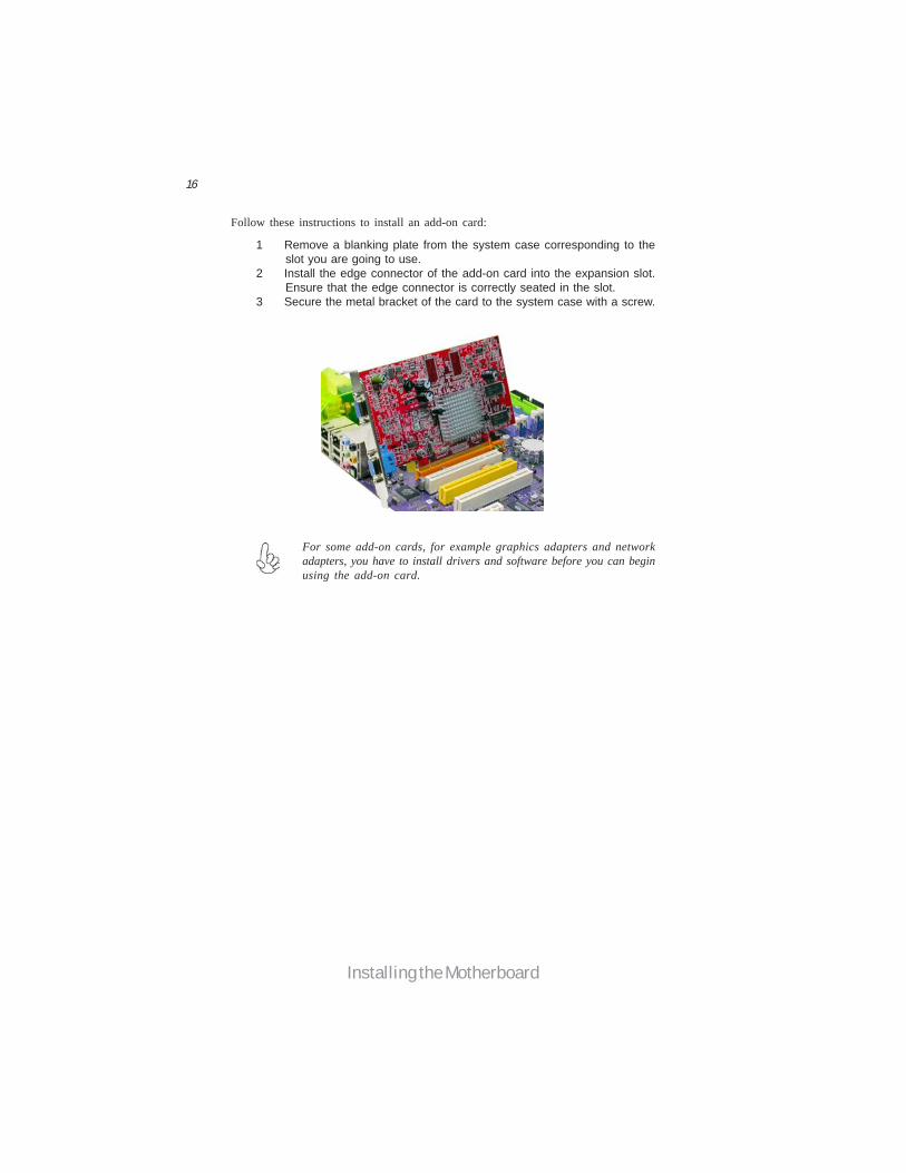
Follow these instructions to install an add-on card:
1 Remove a blanking plate from the system case corresponding to theslot you are going to use.
2 Install the edge connector of the add-on card into the expansion slot.Ensure that the edge connector is correctly seated in the slot.
3 Secure the metal bracket of the card to the system case with a screw.
For some add-on cards, for example graphics adapters and networkadapters, you have to install drivers and software before you can beginusing the add-on card.
17
Installing the Motherboard
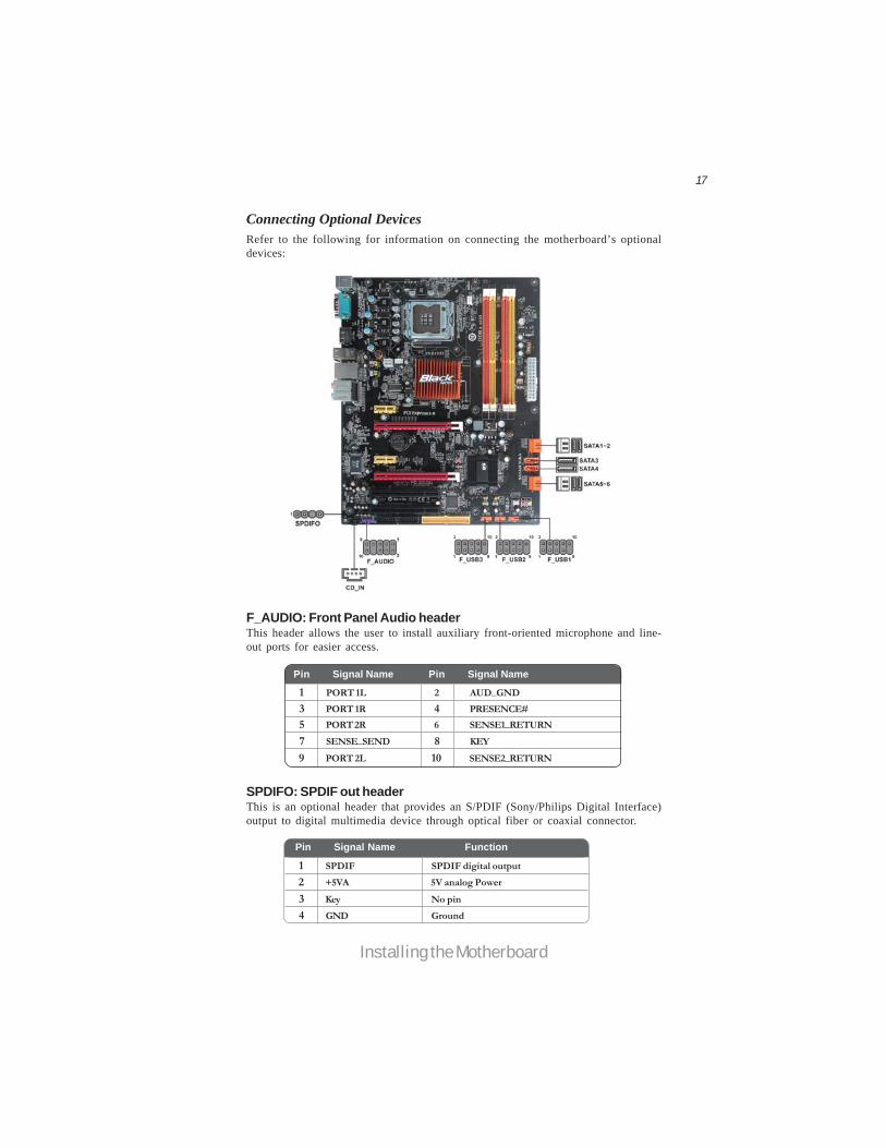
Connecting Optional DevicesRefer to the following for information on connecting the motherboard’s optionaldevices:
F_AUDIO: Front Panel Audio headerThis header allows the user to install auxiliary front-oriented microphone and line-out ports for easier access.
SPDIFO: SPDIF out headerThis is an optional header that provides an S/PDIF (Sony/Philips Digital Interface)output to digital multimedia device through optical fiber or coaxial connector.
Pin Signal Name Function1 PORT 1L 2 AUD_GND3 PORT 1R 4 PRESENCE#5 PORT 2R 6 SENSE1_RETURN7 SENSE_SEND 8 KEY
Pin Signal Name
9 PORT 2L 10 SENSE2_RETURN
Pin Signal Name
1 SPDIF SPDIF digital output2 +5VA 5V analog Power
3 Key No pin4 GND Ground
Pin Signal Name Function
18
Installing the Motherboard
F_USB1~3: Front Panel USB headersThe motherboard has six USB ports installed on the rear edge I/O port array. Addi-tionally, some computer cases have USB ports at the front of the case. If you havethis kind of case, use auxiliary USB connector to connect the front-mounted ports tothe motherboard.
Please make sure that the USB cable has the same pin assignment asindicated above. A different pin assignment may cause damage or systemhang-up.
1 USBPWR Front Panel USB Power2 USBPWR Front Panel USB Power3 USB_FP_P0- USB Port 0 Negative Signal4 USB_FP_P1- USB Port 1 Negative Signal5 USB_FP_P0+ USB Port 0 Positive Signal6 USB_FP_P1+ USB Port 1 Positive Signal7 GND Ground8 GND Ground9 Key No pin10 NC Not connected
FunctionPin Signal Name
SATA1~6: Serial ATA connectorsThese connectors are used to support the new Serial ATA devices for the highest datetransfer rates (3.0 Gb/s), simpler disk drive cabling and easier PC assembly. It elimi-nates limitations of the current Parallel ATA interface. But maintains register com-patibility and software compatibility with Parallel ATA.
1 Ground 2 TX+3 TX- 4 Ground5 RX- 6 RX+7 Ground - -
Pin Signal Name Pin Signal Name
CD_IN: Analog Audio Input connector
Pin Signal Name Function1 CD_L CD In left channel2 GND Ground3 GND Ground4 CD_R CD In right channel

19
Installing the Motherboard
IDE devices enclose jumpers or switches used to set the IDE device as MASTER orSLAVE. Refer to the IDE device user’s manual. Installing two IDE devices on onecable, ensure that one device is set to MASTER and the other device is set to SLAVE.The documentation of your IDE device explains how to do this.
Installing a Hard Disk Drive/CD-ROM/SATA Hard DriveThis section describes how to install IDE devices such as a hard disk drive and a CD-ROM drive.
About IDE DevicesYour motherboard has one IDE interface. An IDE ribbon cable supporting two IDEdevices is bundled with the motherboard.
You must orient the cable connector so that the pin1 (color) edge of thecable corresponds to the pin 1 of the I/O port connector.
About SATA ConnectorsYour motherboard features six SATA connectors supporting a total of six drives.SATA refers to Serial ATA (Advanced Technology Attachment) is the standard inter-face for the IDE hard drives which are currently used in most PCs. These connectorsare well designed and will only fit in one orientation. Locate the SATA connectors onthe motherboard and follow the illustration below to install the SATA hard drives.
Installing Serial ATA Hard DrivesTo install the Serial ATA (SATA) hard drives, use the SATA cable that supports theSerial ATA protocol. This SATA cable comes with a SATA power cable. You canconnect either end of the SATA cable to the SATA hard drive or the connector on themotherboard.
SATA cable (optional) SATA power cable (optional)
IDE: IDE ConnectorThis motherboard supports six high data transfer SATA ports with each runs up to 3.0Gb/s. To get better system performance, we recommend users connect the CD-ROMto the IDE channel, and set up the hard drives on the SATA ports.
20
Installing the Motherboard
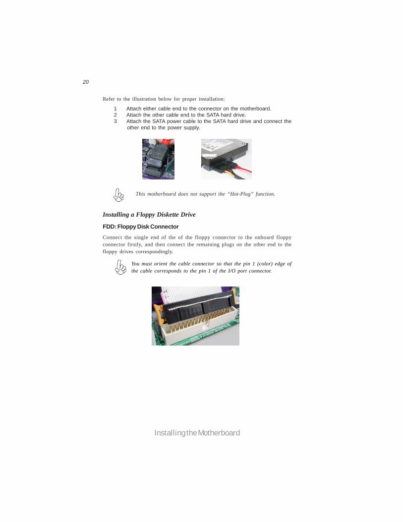
Refer to the illustration below for proper installation:
This motherboard does not support the “Hot-Plug” function.
1 Attach either cable end to the connector on the motherboard.2 Attach the other cable end to the SATA hard drive.3 Attach the SATA power cable to the SATA hard drive and connect the
other end to the power supply.
Installing a Floppy Diskette Drive
You must orient the cable connector so that the pin 1 (color) edge ofthe cable corresponds to the pin 1 of the I/O port connector.
FDD: Floppy Disk Connector
Connect the single end of the of the floppy connector to the onboard floppyconnector firstly, and then connect the remaining plugs on the other end to thefloppy drives correspondingly.
21
Installing the Motherboard
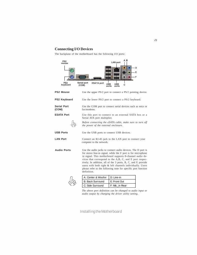
Connecting I/O DevicesThe backplane of the motherboard has the following I/O ports:
PS2 Mouse Use the upper PS/2 port to connect a PS/2 pointing device.
PS2 Keyboard Use the lower PS/2 port to connect a PS/2 keyboard.
Serial Port Use the COM port to connect serial devices such as mice or(COM) fax/modems.
USB Ports Use the USB ports to connect USB devices.
The above port definition can be changed to audio input oraudio output by changing the driver utility setting.
Audio Ports Use the audio jacks to connect audio devices. The D port isfor stereo line-in signal, while the F port is for microphonein signal. This motherboard supports 8-channel audio de-vices that correspond to the A,B, C, and E port respec-tively. In addition, all of the 3 ports, B, C, and E provideusers with both right & left channels individually. Usersplease refer to the following note for specific port functiondefinition.
LAN Port Connect an RJ-45 jack to the LAN port to connect your computer to the network.
ESATA Port Use this port to connect to an external SATA box or aSerial ATA port multiplier.
Before connecting the eSATA cable, make sure to turn offthe power of the external enclosure.
A: Center & Woofer D: Line-in B: Back Surround E: Front Out C: Side Surround F: Mic_in Rear
22
Installing the Motherboard
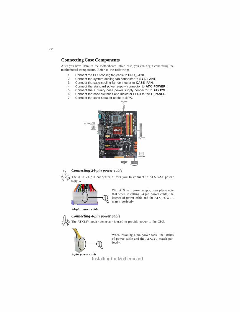
Connecting Case ComponentsAfter you have installed the motherboard into a case, you can begin connecting themotherboard components. Refer to the following:
1 Connect the CPU cooling fan cable to CPU_FAN1.2 Connect the system cooling fan connector to SYS_FAN1.3 Connect the case cooling fan connector to CASE_FAN.4 Connect the standard power supply connector to ATX_POWER.5 Connect the auxiliary case power supply connector to ATX12V.6 Connect the case switches and indicator LEDs to the F_PANEL.7 Connect the case speaker cable to SPK.
The ATX 24-pin connector allows you to connect to ATX v2.x powersupply.
With ATX v2.x power supply, users please notethat when installing 24-pin power cable, thelatches of power cable and the ATX_POWERmatch perfectly.
Connecting 24-pin power cable
24-pin power cable
The ATX12V power connector is used to provide power to the CPU.
When installing 4-pin power cable, the latchesof power cable and the ATX12V match per-fectly.
Connecting 4-pin power cable
4-pin power cable
23
Installing the Motherboard
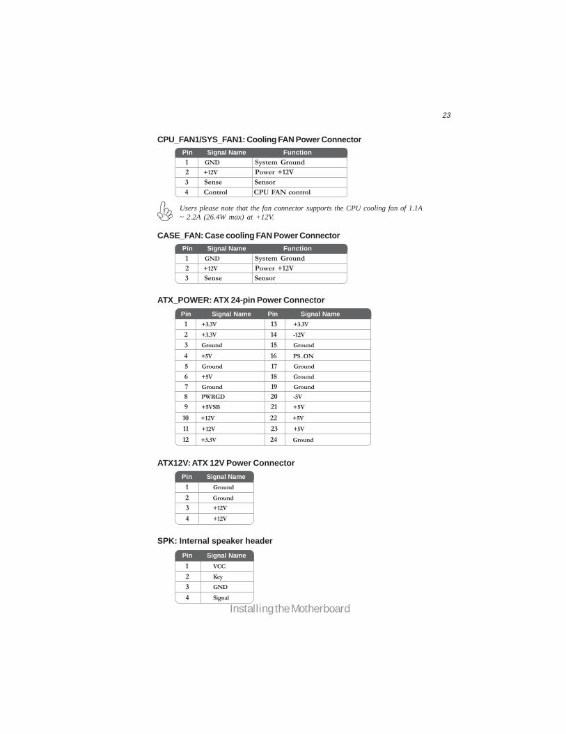
ATX12V: ATX 12V Power Connector
Users please note that the fan connector supports the CPU cooling fan of 1.1A~ 2.2A (26.4W max) at +12V.
ATX_POWER: ATX 24-pin Power Connector
CPU_FAN1/SYS_FAN1: Cooling FAN Power Connector
Pin Signal Name
4 +12V3 +12V2 Ground1 Ground
1 GND System Ground
3 Sense Sensor4 Control CPU FAN control
Pin Signal Name Function
2 +12V Power +12V
CASE_FAN: Case cooling FAN Power Connector
Pin Signal Name Pin Signal Name1 +3.3V 13 +3.3V2 +3.3V 14 -12V3 Ground 15 Ground4 +5V 16 PS_ON5 Ground 17 Ground6 +5V 18 Ground7 Ground 19 Ground8 PWRGD 20 -5V9 +5VSB 21 +5V
10 +12V 22 +5V11 +12V 23 +5V12 +3.3V 24 Ground
1 GND System Ground
3 Sense Sensor
Pin Signal Name Function
2 +12V Power +12V
SPK: Internal speaker header
4 Signal3 GND2 Key1 VCC
Pin Signal Name
24
Installing the Motherboard
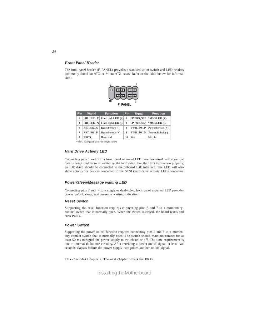
Front Panel HeaderThe front panel header (F_PANEL) provides a standard set of switch and LED headerscommonly found on ATX or Micro ATX cases. Refer to the table below for informa-tion:
Reset Switch
Supporting the reset function requires connecting pins 5 and 7 to a momentary-contact switch that is normally open. When the switch is closed, the board resets andruns POST.
Power/Sleep/Message waiting LED
Connecting pins 2 and 4 to a single or dual-color, front panel mounted LED providespower on/off, sleep, and message waiting indication.
Hard Drive Activity LED
Connecting pins 1 and 3 to a front panel mounted LED provides visual indication thatdata is being read from or written to the hard drive. For the LED to function properly,an IDE drive should be connected to the onboard IDE interface. The LED will alsoshow activity for devices connected to the SCSI (hard drive activity LED) connector.
Pin Signal Function Pin Signal Function1 HD_LED_P Hard disk LED (+) 2 FP PWR/SLP *MSG LED (+)3 HD_LED_N Hard disk LED (-)5 RST_SW_N Reset Switch (-)7 RST_SW_P Reset Switch (+)9 RSVD Reserved
4 FP PWR/SLP *MSG LED (-)6 PWR_SW_P Power Switch (+)8 PWR_SW_N Power Switch (-)10 Key No pin
* MSG LED (dual color or single color)
Power Switch
Supporting the power on/off function requires connecting pins 6 and 8 to a momen-tary-contact switch that is normally open. The switch should maintain contact for atleast 50 ms to signal the power supply to switch on or off. The time requirement isdue to internal de-bounce circuitry. After receiving a power on/off signal, at least twoseconds elapses before the power supply recognizes another on/off signal.
This concludes Chapter 2. The next chapter covers the BIOS.

25
Using BIOS
Chapter 3Using BIOS
About the Setup UtilityThe computer uses the latest “American Megatrends Inc. ” BIOS with support forWindows Plug and Play. The CMOS chip on the motherboard contains the ROMsetup instructions for configuring the motherboard BIOS.
The BIOS (Basic Input and Output System) Setup Utility displays the system’sconfiguration status and provides you with options to set system parameters. Theparameters are stored in battery-backed-up CMOS RAM that saves this informationwhen the power is turned off. When the system is turned back on, the system isconfigured with the values you stored in CMOS.
The BIOS Setup Utility enables you to configure:
• Hard drives, diskette drives and peripherals• Video display type and display options• Password protection from unauthorized use• Power Management features
The settings made in the Setup Utility affect how the computer performs. Beforeusing the Setup Utility, ensure that you understand the Setup Utility options.
This chapter provides explanations for Setup Utility options.
The Standard ConfigurationA standard configuration has already been set in the Setup Utility. However, werecommend that you read this chapter in case you need to make any changes in thefuture.
This Setup Utility should be used:• when changing the system configuration• when a configuration error is detected and you are prompted to make
changes to the Setup Utility• when trying to resolve IRQ conflicts• when making changes to the Power Management configuration• when changing the password or making other changes to the Security
Setup
Entering the Setup UtilityWhen you power on the system, BIOS enters the Power-On Self Test (POST)routines. POST is a series of built-in diagnostics performed by the BIOS. After thePOST routines are completed, the following message appears:Press DEL to enter SETUP
26
Using BIOS
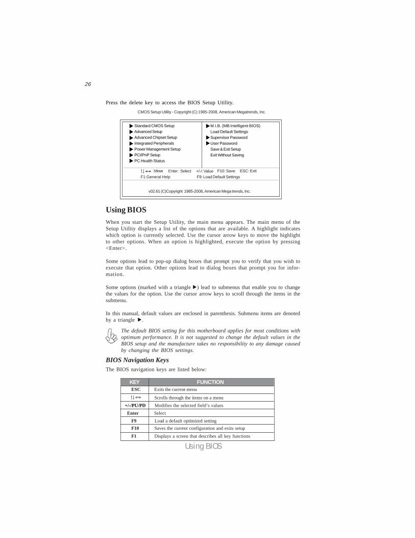
Press the delete key to access the BIOS Setup Utility.
CMOS Setup Utility - Copyright (C) 1985-2008, American Megatrends, Inc.
v02.61 (C)Copyright 1985-2008, American Mega trends, Inc.
: Move F10: Save ESC: Exit+/-/: ValueEnter : SelectF9: Load Default Settings F1:General Help
Standard CMOS SetupAdvanced SetupAdvanced Chipset SetupIntegrated PeripheralsPower Management SetupPCI/PnP SetupPC Health Status
M.I.B. (MB Intelligent BIOS)Load Default SettingsSupervisor PasswordUser PasswordSave & Exit SetupExit Without Saving
< >
BIOS Navigation KeysThe BIOS navigation keys are listed below:
Enter Select
KEY FUNCTION
Scrolls through the items on a menu+/-/PU/PD Modifies the selected field’s values
F10 Saves the current configuration and exits setup
F1 Displays a screen that describes all key functions
F9 Load a default optimized setting
ESC Exits the current menu
< >
Using BIOSWhen you start the Setup Utility, the main menu appears. The main menu of theSetup Utility displays a list of the options that are available. A highlight indicateswhich option is currently selected. Use the cursor arrow keys to move the highlightto other options. When an option is highlighted, execute the option by pressing<Enter>.
Some options lead to pop-up dialog boxes that prompt you to verify that you wish toexecute that option. Other options lead to dialog boxes that prompt you for infor-mation.
Some options (marked with a triangle ) lead to submenus that enable you to changethe values for the option. Use the cursor arrow keys to scroll through the items in thesubmenu.
In this manual, default values are enclosed in parenthesis. Submenu items are denotedby a triangle .
The default BIOS setting for this motherboard applies for most conditions withoptimum performance. It is not suggested to change the default values in theBIOS setup and the manufacture takes no responsibility to any damage causedby changing the BIOS settings.
27
Using BIOS: Move F10: Save ESC: ExitEnter : Select +/-/: Value
F9: Load Default settingsF1: General Help < >
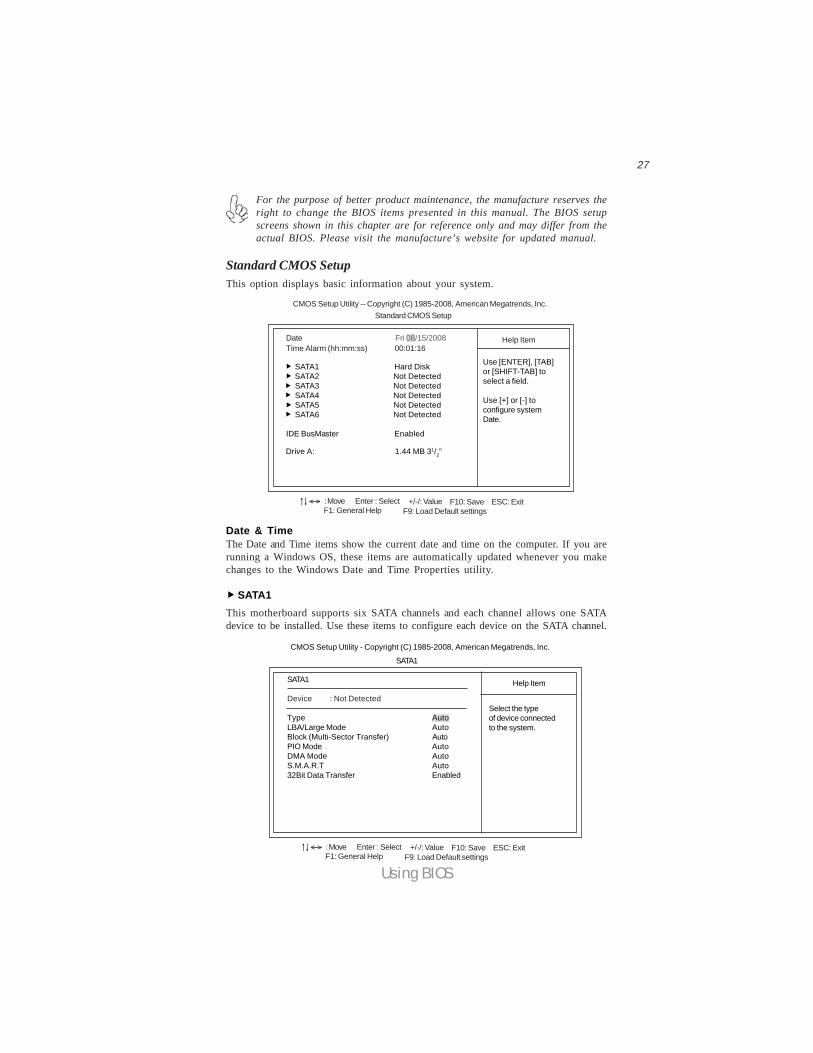
Standard CMOS SetupThis option displays basic information about your system.
Date Fri 08/15/2008
SATA1 Hard Disk SATA2 Not Detected SATA3 Not Detected SATA4 Not Detected SATA5 Not Detected SATA6 Not Detected
Help Item
CMOS Setup Utility -- Copyright (C) 1985-2008, American Megatrends, Inc.
Time Alarm (hh:mm:ss) 00:01:16
Use [ENTER], [TAB]or [SHIFT-TAB] toselect a field.
Use [+] or [-] toconfigure systemDate.
Standard CMOS Setup
Date & TimeThe Date and Time items show the current date and time on the computer. If you arerunning a Windows OS, these items are automatically updated whenever you makechanges to the Windows Date and Time Properties utility.
SATA1
CMOS Setup Utility - Copyright (C) 1985-2008, American Megatrends, Inc.
SATA1
Device : Not Detected
Type AutoLBA/Large Mode AutoBlock (Multi-Sector Transfer) AutoPIO Mode AutoDMA Mode AutoS.M.A.R.T Auto32Bit Data Transfer Enabled
Help Item
Select the typeof device connectedto the system.
IDE BusMaster Enabled
Drive A: 1.44 MB 31/2”
: Move F10: Save ESC: ExitEnter : Select +/-/: ValueF9: Load Default settingsF1: General Help
< >
This motherboard supports six SATA channels and each channel allows one SATAdevice to be installed. Use these items to configure each device on the SATA channel.
SATA1
For the purpose of better product maintenance, the manufacture reserves theright to change the BIOS items presented in this manual. The BIOS setupscreens shown in this chapter are for reference only and may differ from theactual BIOS. Please visit the manufacture’s website for updated manual.
28
Using BIOS
IDE BusMaster (Enabled)This item enables or disables the DMA under DOS mode. We recommend you to leavethis item at the default value.
Press <Esc> to return to the main menu setting page.
Block (Multi-Sector Transfer) (Auto)If the feature is enabled, it will enhance hard disk performance by reading or writingmore data during each transfer.PIO Mode (Auto)Use this item to set the PIO mode to enhance hard disk performance by optimizingthe hard disk timing.DMA Mode (Auto)DMA capability allows user to improve the transfer-speed and data-integrity forcompatible IDE devices.S.M.A.R.T. (Auto)The S.M.A.R.T. (Self-Monitoring, Analysis and Reporting Technology) system is adiagnostics technology that monitors and predicts device performance. S.M.A.R.T.software resides on both the disk drive and the host computer.
32Bit Data Transfer (Enabled)Use this item to enable or disable 32Bit Data Transfer.
Press <Esc> to return to the Standard CMOS Setup page.
Drive A: (1.44 MB 31/2”)This item defines the characteristics of any diskette drive attached to the system.Only one diskette drive is supported.
LBA/Large Mode (Auto)Use this item to set the LBA/Large mode to enhance hard disk performance byoptimizing the area the hard disk is visited each time.
Type (Auto)Use this item to configure the type of the IDE device that you specify. If the featureis enabled, it will enhance hard disk performance by reading or writing more dataduring each transfer.
29
Using BIOS
Limit CPUID MaxVal (Disabled)
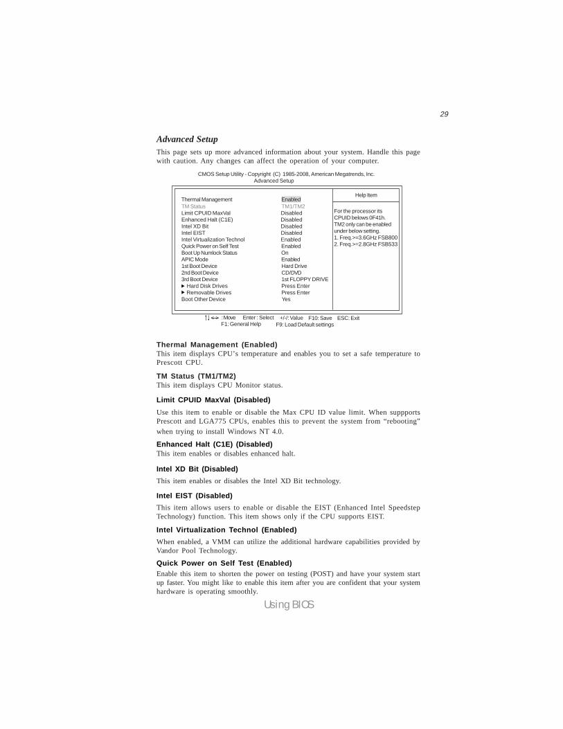
Advanced SetupThis page sets up more advanced information about your system. Handle this pagewith caution. Any changes can affect the operation of your computer.
CMOS Setup Utility - Copyright (C) 1985-2008, American Megatrends, Inc. Advanced Setup
TM Status TM1/TM2Limit CPUID MaxVal DisabledEnhanced Halt (C1E) DisabledIntel XD Bit DisabledIntel EIST DisabledIntel Virtualization Technol EnabledQuick Power on Self Test EnabledBoot Up Numlock Status OnAPIC Mode Enabled1st Boot Device Hard Drive2nd Boot Device CD/DVD3rd Boot Device 1st FLOPPY DRIVE Hard Disk Drives Press Enter Removable Drives Press EnterBoot Other Device Yes
For the processor itsCPUID belows 0F41h.TM2 only can be enabledunder below setting.1. Freq.>=3.6GHz FSB8002. Freq.>=2.8GHz FSB533
Help ItemThermal Management Enabled
: Move F10: Save ESC: ExitEnter : Select +/-/: ValueF9: Load Default settingsF1: General Help
< >
Enhanced Halt (C1E) (Disabled)
Intel XD Bit (Disabled)
Intel EIST (Disabled)
Intel Virtualization Technol (Enabled)
Thermal Management (Enabled)This item displays CPU’s temperature and enables you to set a safe temperature toPrescott CPU.
TM Status (TM1/TM2)This item displays CPU Monitor status.
Use this item to enable or disable the Max CPU ID value limit. When suppportsPrescott and LGA775 CPUs, enables this to prevent the system from “rebooting”when trying to install Windows NT 4.0.
This item enables or disables enhanced halt.
This item enables or disables the Intel XD Bit technology.
When enabled, a VMM can utilize the additional hardware capabilities provided byVandor Pool Technology.
This item allows users to enable or disable the EIST (Enhanced Intel SpeedstepTechnology) function. This item shows only if the CPU supports EIST.
Quick Power on Self Test (Enabled)Enable this item to shorten the power on testing (POST) and have your system startup faster. You might like to enable this item after you are confident that your systemhardware is operating smoothly.
30
Using BIOS
Boot Up Numlock Status (On)This item defines if the keyboard Num Lock key is active when your system isstarted.APIC Mode (Enabled)This item allows you to enable or disable the APCI (Advanced Programmable Inter-rupt Controller) mode. APIC provides symmetric multi-processing (SMP) for sys-tems, allowing support for up to 60 processors.
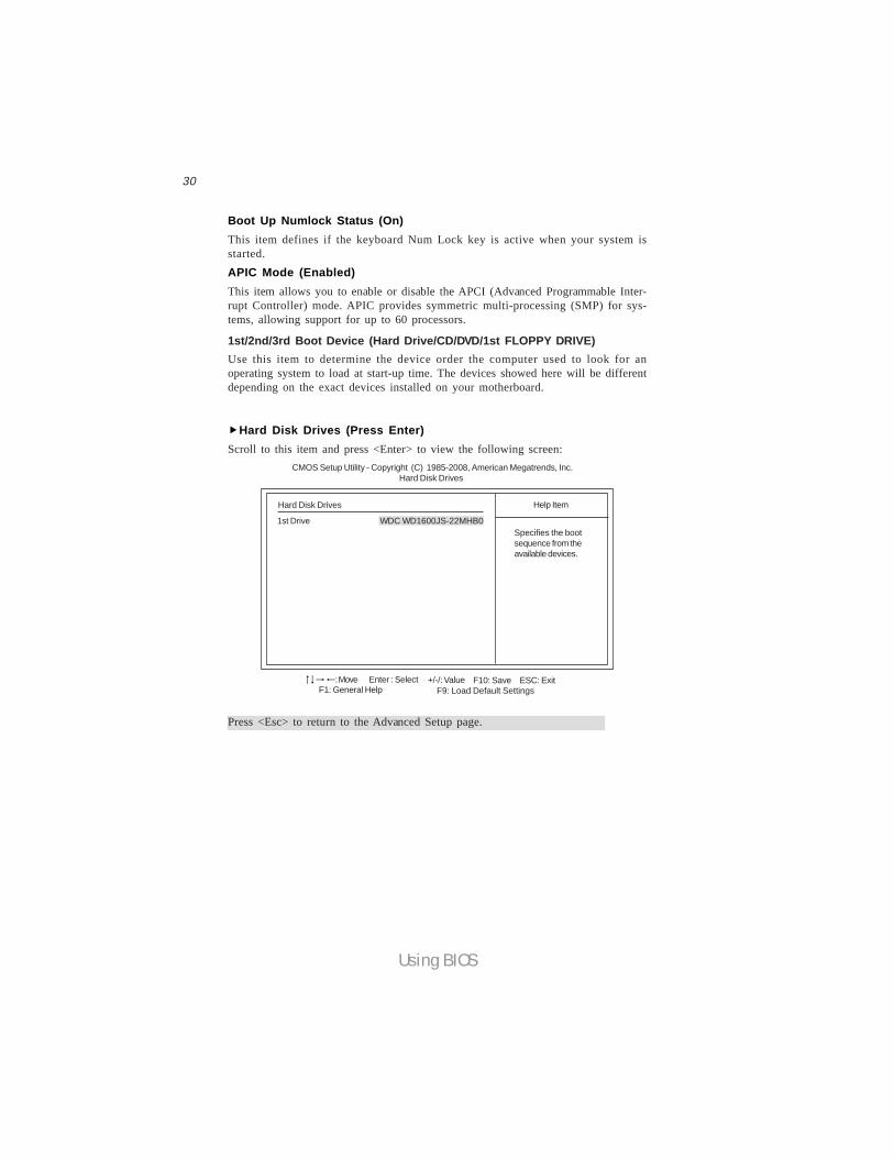
1st/2nd/3rd Boot Device (Hard Drive/CD/DVD/1st FLOPPY DRIVE)Use this item to determine the device order the computer used to look for anoperating system to load at start-up time. The devices showed here will be differentdepending on the exact devices installed on your motherboard.
Hard Disk Drives (Press Enter)Scroll to this item and press <Enter> to view the following screen:
Hard Disk Drives
1st Drive WDC WD1600JS-22MHB0
Help Item
Specifies the bootsequence from theavailable devices.
CMOS Setup Utility - Copyright (C) 1985-2008, American Megatrends, Inc. Hard Disk Drives
Press <Esc> to return to the Advanced Setup page.
: Move F10: Save ESC: ExitEnter : Select +/-/: Value F9: Load Default SettingsF1: General Help
31
Using BIOS
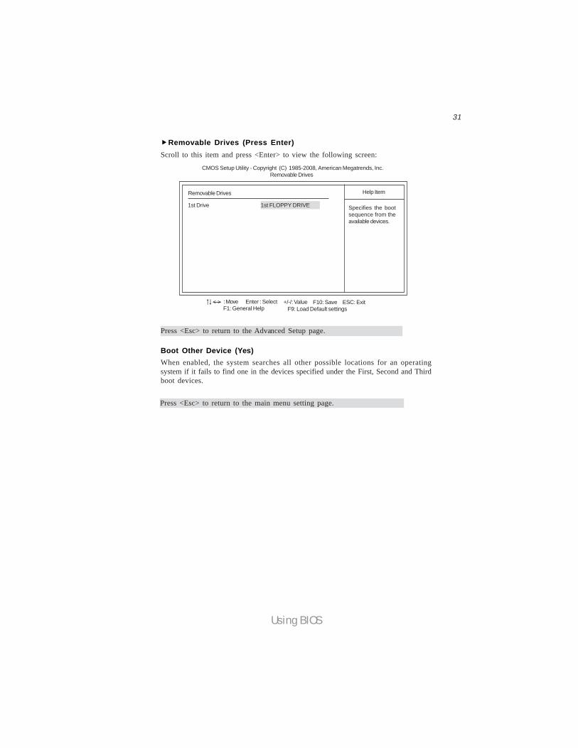
Boot Other Device (Yes)When enabled, the system searches all other possible locations for an operatingsystem if it fails to find one in the devices specified under the First, Second and Thirdboot devices.
Press <Esc> to return to the main menu setting page.
Press <Esc> to return to the Advanced Setup page.
Removable Drives (Press Enter)Scroll to this item and press <Enter> to view the following screen:
Removable Drives
1st Drive 1st FLOPPY DRIVE
Help Item
Specifies the bootsequence from theavailable devices.
CMOS Setup Utility - Copyright (C) 1985-2008, American Megatrends, Inc.Removable Drives
: Move F10: Save ESC: ExitEnter : Select +/-/: ValueF9: Load Default settingsF1: General Help
< >
32
Using BIOS
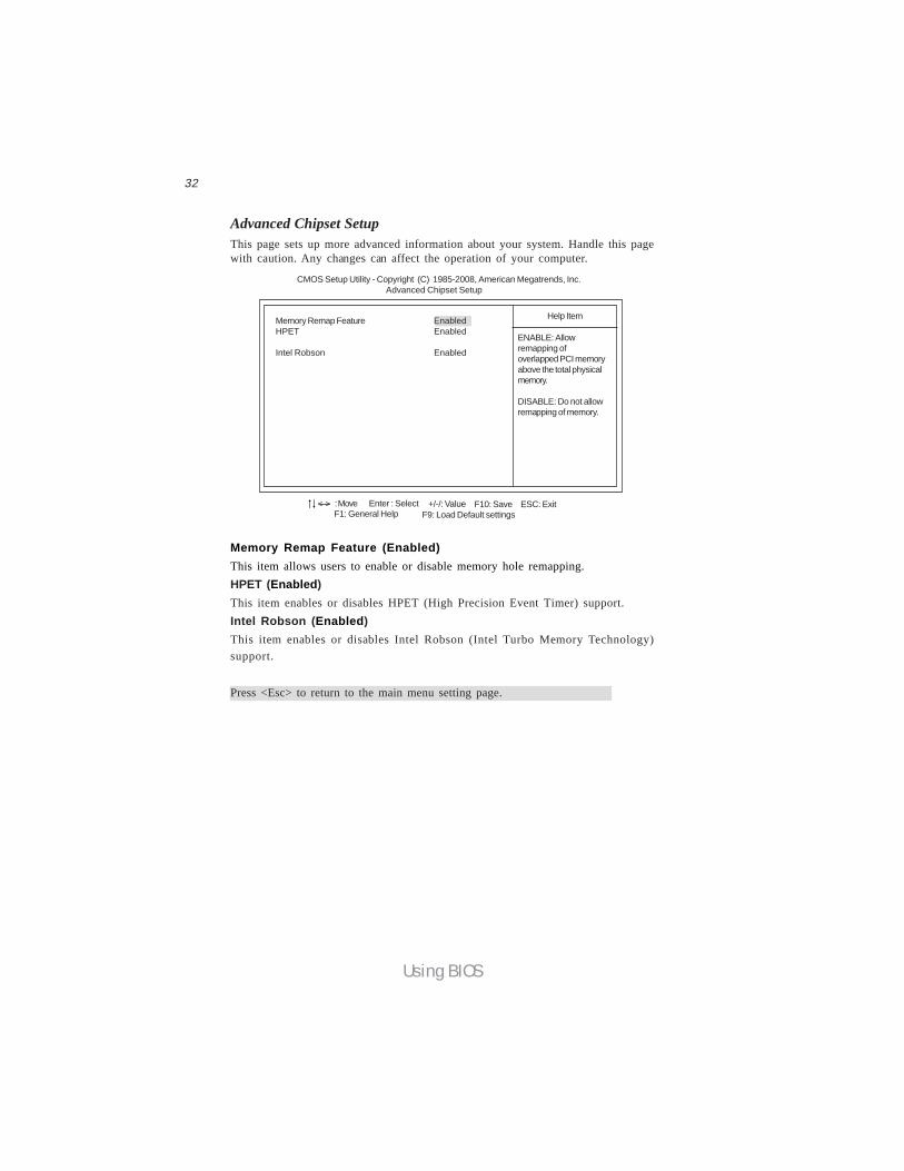
Memory Remap Feature (Enabled)This item allows users to enable or disable memory hole remapping.HPET (Enabled)This item enables or disables HPET (High Precision Event Timer) support.Intel Robson (Enabled)This item enables or disables Intel Robson (Intel Turbo Memory Technology)support.
Advanced Chipset SetupThis page sets up more advanced information about your system. Handle this pagewith caution. Any changes can affect the operation of your computer.
CMOS Setup Utility - Copyright (C) 1985-2008, American Megatrends, Inc. Advanced Chipset Setup
Memory Remap Feature EnabledHPET Enabled
Intel Robson Enabled
Help Item
: Move F10: Save ESC: ExitEnter : Select +/-/: ValueF9: Load Default settingsF1: General Help
< >
ENABLE: Allowremapping ofoverlapped PCI memoryabove the total physicalmemory.
DISABLE: Do not allowremapping of memory.
Press <Esc> to return to the main menu setting page.
33
Using BIOS
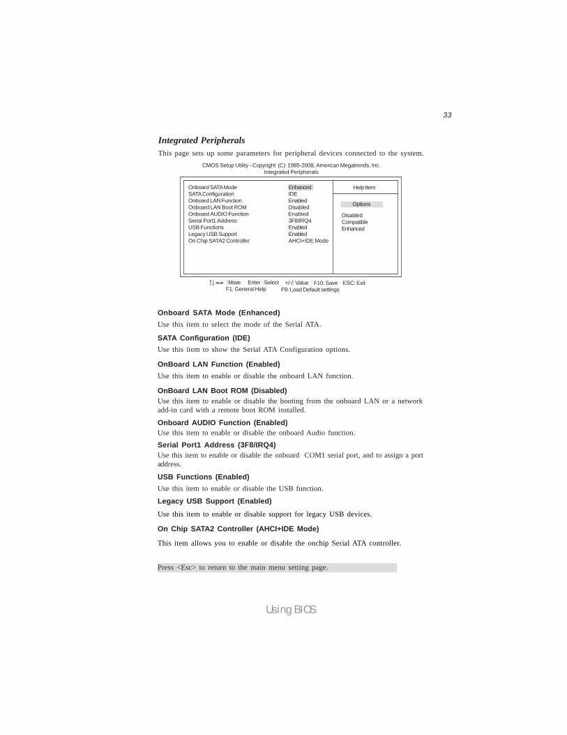
Onboard SATA Mode (Enhanced)
SATA Configuration (IDE)
Onboard AUDIO Function (Enabled)
USB Functions (Enabled)
On Chip SATA2 Controller (AHCI+IDE Mode)
This item allows you to enable or disable the onchip Serial ATA controller.
OnBoard LAN Function (Enabled)Use this item to enable or disable the onboard LAN function.
OnBoard LAN Boot ROM (Disabled)Use this item to enable or disable the booting from the onboard LAN or a networkadd-in card with a remote boot ROM installed.
Serial Port1 Address (3F8/IRQ4)Use this item to enable or disable the onboard COM1 serial port, and to assign a portaddress.
Legacy USB Support (Enabled)Use this item to enable or disable support for legacy USB devices.
Press <Esc> to return to the main menu setting page.
Use this item to enable or disable the onboard Audio function.
Use this item to enable or disable the USB function.
Use this item to select the mode of the Serial ATA.
Use this item to show the Serial ATA Configuration options.
Integrated PeripheralsThis page sets up some parameters for peripheral devices connected to the system.
CMOS Setup Utility - Copyright (C) 1985-2008, American Megatrends, Inc. Integrated Peripherals
Onboard SATA Mode EnhancedSATA Configuration IDEOnboard LAN Function EnabledOnboard LAN Boot ROM DisabledOnboard AUDIO Function EnabledSerial Port1 Address 3F8/IRQ4USB Functions EnabledLegacy USB Support EnabledOn Chip SATA2 Controller AHCI+IDE Mode
Help Item
: Move F10: Save ESC: ExitEnter : Select +/-/: ValueF9: Load Default settingsF1: General Help
< >
Options
DisabledCompatibleEnhanced
34
Using BIOS
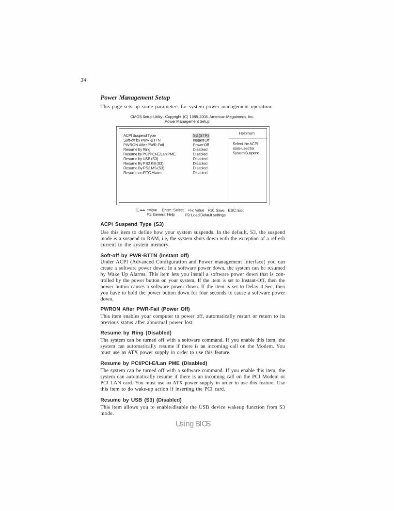
Soft-off by PWR-BTTN (Instant off)Under ACPI (Advanced Configuration and Power management Interface) you cancreate a software power down. In a software power down, the system can be resumedby Wake Up Alarms. This item lets you install a software power down that is con-trolled by the power button on your system. If the item is set to Instant-Off, then thepower button causes a software power down. If the item is set to Delay 4 Sec, thenyou have to hold the power button down for four seconds to cause a software powerdown.
PWRON After PWR-Fail (Power Off)This item enables your computer to power off, automatically restart or return to itsprevious status after abnormal power lost.
Resume by Ring (Disabled)The system can be turned off with a software command. If you enable this item, thesystem can automatically resume if there is an incoming call on the Modem. Youmust use an ATX power supply in order to use this feature.
Resume by PCI/PCI-E/Lan PME (Disabled)The system can be turned off with a software command. If you enable this item, thesystem can automatically resume if there is an incoming call on the PCI Modem orPCI LAN card. You must use an ATX power supply in order to use this feature. Usethis item to do wake-up action if inserting the PCI card.
ACPI Suspend Type (S3)Use this item to define how your system suspends. In the default, S3, the suspendmode is a suspend to RAM, i.e, the system shuts down with the exception of a refreshcurrent to the system memory.
Power Management SetupThis page sets up some parameters for system power management operation.
Select the ACPIstate used forSystem Suspend.
Help Item
CMOS Setup Utility - Copyright (C) 1985-2008, American Megatrends, Inc. Power Management Setup
ACPI Suspend Type S3 (STR)Soft-off by PWR-BTTN Instant OffPWRON After PWR-Fail Power OffResume by Ring DisabledResume by PCI/PCI-E/Lan PME DisabledResume by USB (S3) DisabledResume By PS2 KB (S3) DisabledResume By PS2 MS (S3) DisabledResume on RTC Alarm Disabled
: Move F10: Save ESC: ExitEnter : Select +/-/: ValueF9: Load Default settingsF1: General Help
< >
Resume by USB (S3) (Disabled)This item allows you to enable/disable the USB device wakeup function from S3mode.
35
Using BIOS
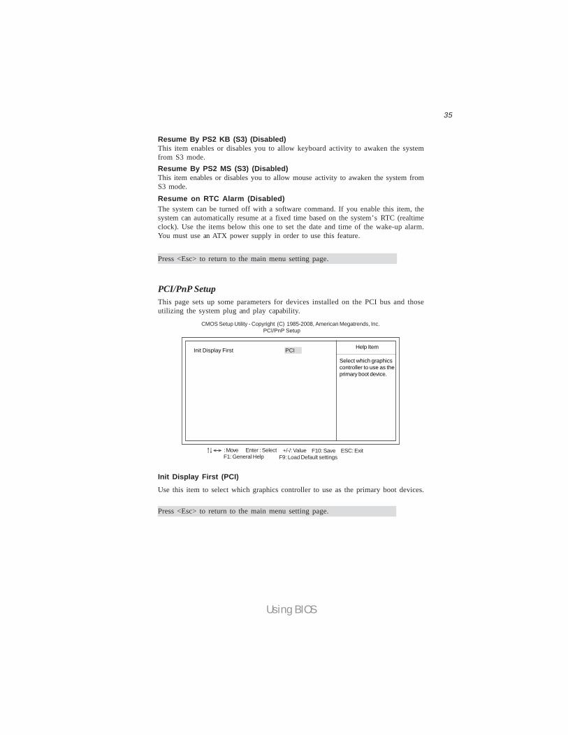
Resume By PS2 MS (S3) (Disabled)This item enables or disables you to allow mouse activity to awaken the system fromS3 mode.Resume on RTC Alarm (Disabled)The system can be turned off with a software command. If you enable this item, thesystem can automatically resume at a fixed time based on the system’s RTC (realtimeclock). Use the items below this one to set the date and time of the wake-up alarm.You must use an ATX power supply in order to use this feature.
Press <Esc> to return to the main menu setting page.
PCI/PnP SetupThis page sets up some parameters for devices installed on the PCI bus and thoseutilizing the system plug and play capability.
Help Item
CMOS Setup Utility - Copyright (C) 1985-2008, American Megatrends, Inc. PCI/PnP Setup
Init Display First PCI
Init Display First (PCI)Use this item to select which graphics controller to use as the primary boot devices.
Select which graphicscontroller to use as theprimary boot device.
: Move F10: Save ESC: ExitEnter : Select +/-/: ValueF9: Load Default settingsF1: General Help
< >
Press <Esc> to return to the main menu setting page.
Resume By PS2 KB (S3) (Disabled)This item enables or disables you to allow keyboard activity to awaken the systemfrom S3 mode.
36
Using BIOS
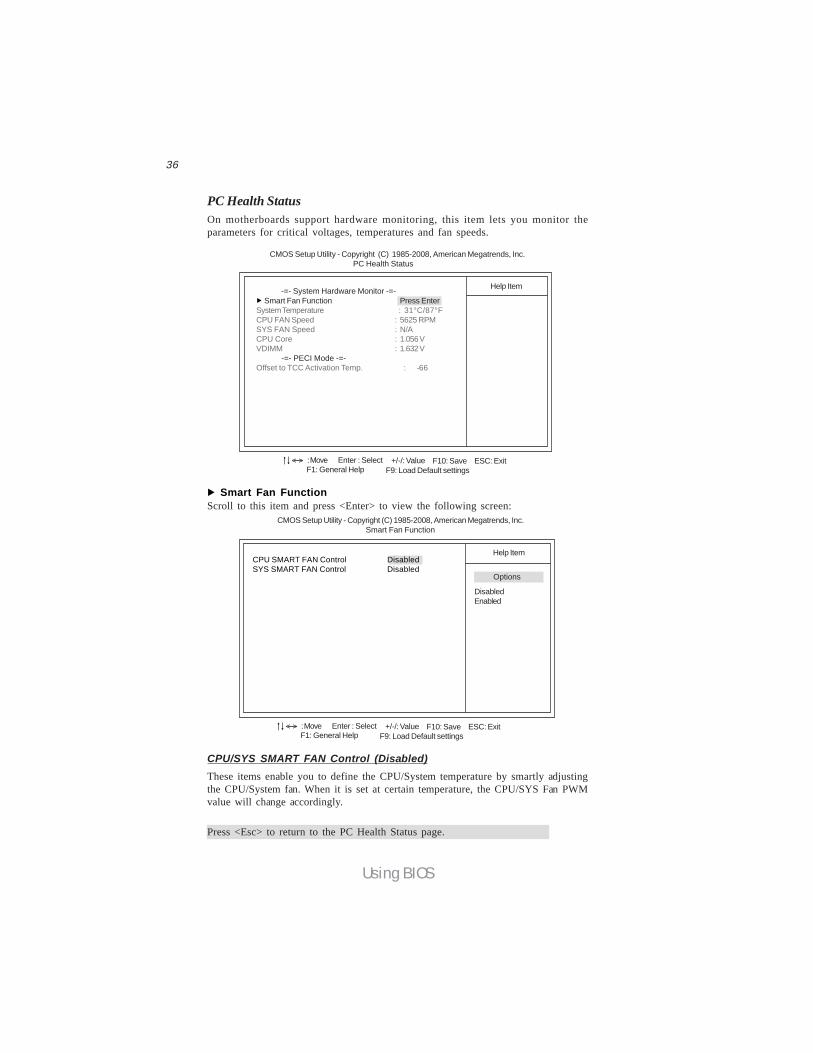
PC Health StatusOn motherboards support hardware monitoring, this item lets you monitor theparameters for critical voltages, temperatures and fan speeds.
Smart Fan Function Press EnterSystem Temperature : 31°C/87°FCPU FAN Speed : 5625 RPMSYS FAN Speed : N/ACPU Core : 1.056 VVDIMM : 1.632 V -=- PECI Mode -=-Offset to TCC Activation Temp. : -66
Help Item
CMOS Setup Utility - Copyright (C) 1985-2008, American Megatrends, Inc. PC Health Status
CMOS Setup Utility - Copyright (C) 1985-2008, American Megatrends, Inc. Smart Fan Function
Help ItemCPU SMART FAN Control DisabledSYS SMART FAN Control Disabled
Smart Fan FunctionScroll to this item and press <Enter> to view the following screen:
DisabledEnabled
Options
: Move F10: Save ESC: ExitEnter : Select +/-/: ValueF9: Load Default settingsF1: General Help
< >
: Move F10: Save ESC: ExitEnter : Select +/-/: ValueF9: Load Default settingsF1: General Help
< >
-=- System Hardware Monitor -=-
CPU/SYS SMART FAN Control (Disabled)
Press <Esc> to return to the PC Health Status page.
These items enable you to define the CPU/System temperature by smartly adjustingthe CPU/System fan. When it is set at certain temperature, the CPU/SYS Fan PWMvalue will change accordingly.
37
Using BIOS
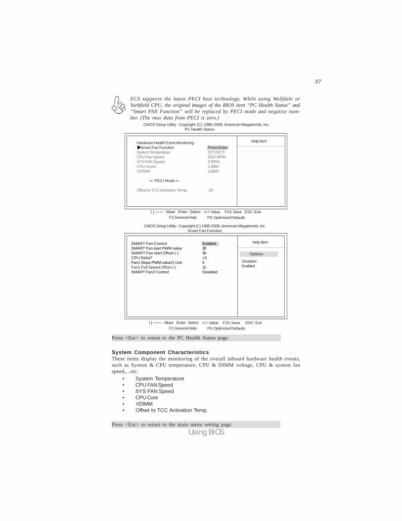
ECS supports the latest PECI host technology. While using Wolfdale orYorkfield CPU, the original images of the BIOS item “PC Health Status” and“Smart FAN Function” will be replaced by PECI mode and negative num-ber. (The max data from PECI is zero.)
Hardware Health Event Monitoring Smart Fan Function Press EnterSystem Temperature 33°C/91°FCPU Fan Speed: 2537 RPMSYS FAN Speed: 0 RPMCPU Vcore: 1.280VVDIMM: 1.840V
-=- PECI Mode-=-
Offset to TCC Activation Temp.: -20
Help Item
CMOS Setup Utility - Copyright (C) 1985-2008, American Megatrends, Inc. PC Health Status
F10: Save ESC: Exit+/-/: ValueEnter : SelectF9: Optimized DefaultsF1:General Help
: Move
Press <Esc> to return to the PC Health Status page.
CMOS Setup Utility - Copyright (C) 1985-2008, American Megatrends, Inc. Smart Fan Function
Help ItemSMART Fan Control EnabledSMART Fan start PWM value 28SMART Fan start Offset (-) 30CPU DeltaT +3Fan1 Slope PWM value/1 Unit 5Fan1 Full Speed Offset (-) 10SMART Fan2 Control Disabled
DisabledEnabled
F10: Save ESC: Exit+/-/: ValueEnter : SelectF9: Optimized DefaultsF1:General Help
: Move
Options
System Component CharacteristicsThese items display the monitoring of the overall inboard hardware health events,such as System & CPU temperature, CPU & DIMM voltage, CPU & system fanspeed,...etc. • System Temperature • CPU FAN Speed • SYS FAN Speed • CPU Core • VDIMM • Offset to TCC Activation Temp.
Press <Esc> to return to the main menu setting page.
38
Using BIOS
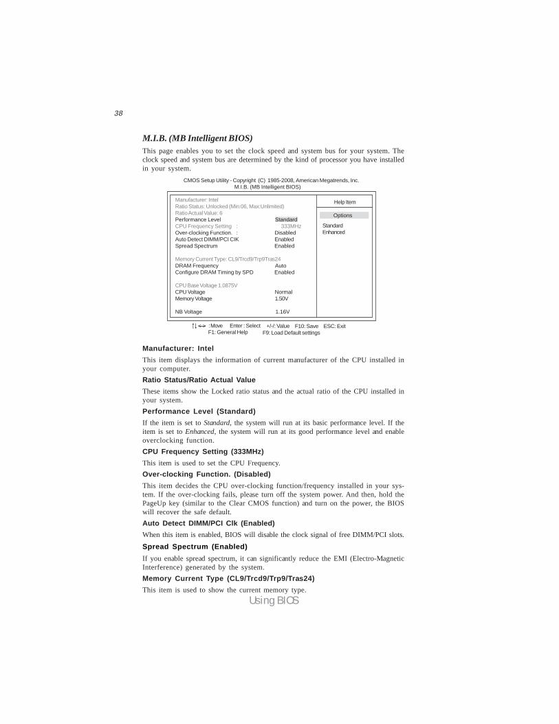
M.I.B. (MB Intelligent BIOS)This page enables you to set the clock speed and system bus for your system. Theclock speed and system bus are determined by the kind of processor you have installedin your system.
Manufacturer: IntelThis item displays the information of current manufacturer of the CPU installed inyour computer.Ratio Status/Ratio Actual ValueThese items show the Locked ratio status and the actual ratio of the CPU installed inyour system.Performance Level (Standard)If the item is set to Standard, the system will run at its basic performance level. If theitem is set to Enhanced, the system will run at its good performance level and enableoverclocking function.CPU Frequency Setting (333MHz)This item is used to set the CPU Frequency.Over-clocking Function. (Disabled)This item decides the CPU over-clocking function/frequency installed in your sys-tem. If the over-clocking fails, please turn off the system power. And then, hold thePageUp key (similar to the Clear CMOS function) and turn on the power, the BIOSwill recover the safe default.Auto Detect DIMM/PCI Clk (Enabled)When this item is enabled, BIOS will disable the clock signal of free DIMM/PCI slots.
Spread Spectrum (Enabled)If you enable spread spectrum, it can significantly reduce the EMI (Electro-MagneticInterference) generated by the system.Memory Current Type (CL9/Trcd9/Trp9/Tras24)This item is used to show the current memory type.
CMOS Setup Utility - Copyright (C) 1985-2008, American Megatrends, Inc. M.I.B. (MB Intelligent BIOS)
Help ItemManufacturer: IntelRatio Status: Unlocked (Min:06, Max:Unlimited)Ratio Actual Value: 6Performance Level StandardCPU Frequency Setting : 333MHzOver-clocking Function. : DisabledAuto Detect DIMM/PCI CIK EnabledSpread Spectrum Enabled
Memory Current Type: CL9/Trcd9/Trp9Tras24DRAM Frequency AutoConfigure DRAM Timing by SPD Enabled
CPU Base Voltage 1.0875V CPU Voltage NormalMemory Voltage 1.50V
NB Voltage 1.16V
: Move F10: Save ESC: ExitEnter : Select +/-/: ValueF9: Load Default settingsF1: General Help
< >
StandardEnhanced
Options
39
Using BIOS
Press <Esc> to return to the main menu setting page.
DRAM Frequency (Auto)This item enables users to adjust the DRAM frequency. The default setting is auto andwe recommend users leave the setting unchanged. Modify it at will may cause thesystem to be unstable.Configure DRAM Timing by SPD (Enabled)This item allows users to enable or disable the DRAM timing defined by the SerialPresence Detect electrical. User please note that if setting this item to auto, thefollowing two items are not available.CPU Base Voltage (1.0875V)This item is used to show the CPU Base voltage.CPU Voltage (Normal)This item allows users to adjust the CPU voltage.Memory Voltage (1.50V)This item allows users to adjust the DDR memory voltage.NB Voltage (1.16V)This item allows users to adjust the northbridge voltage.
40
Using BIOS
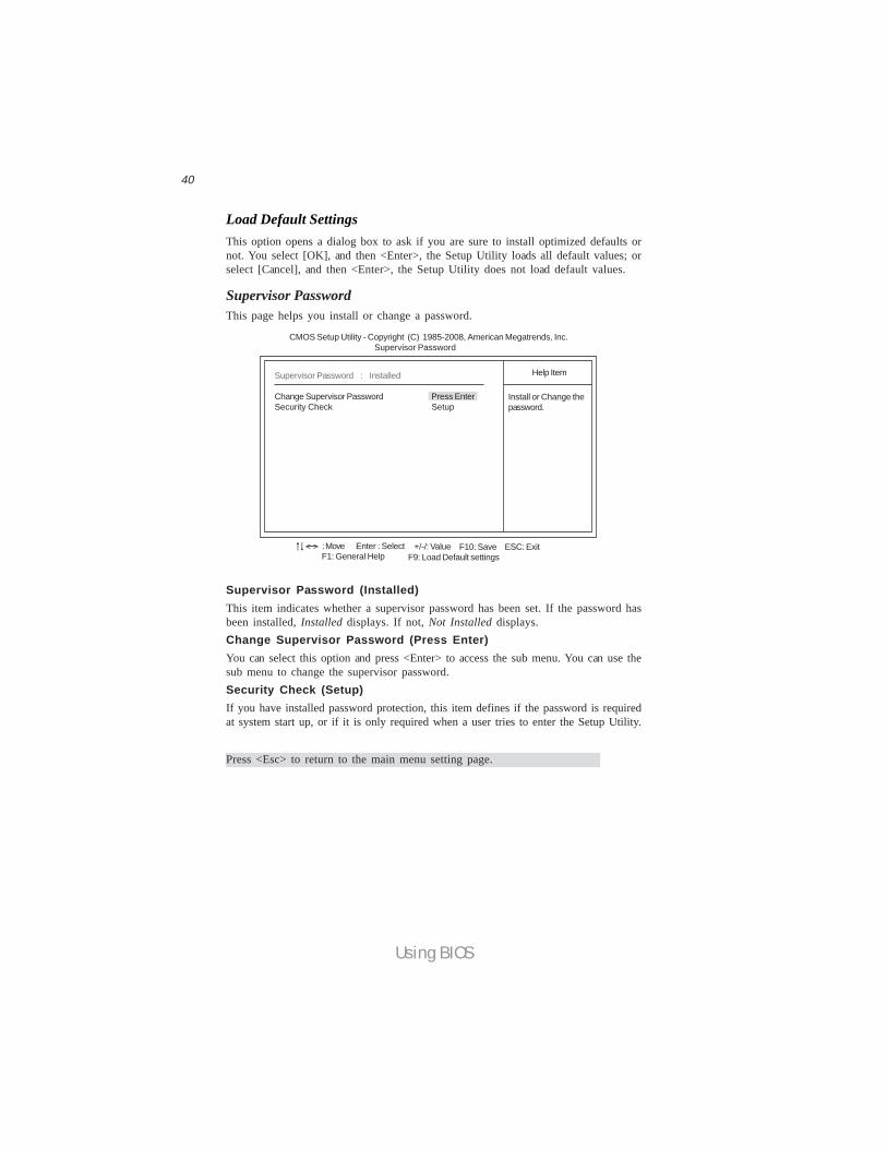
Supervisor Password (Installed)This item indicates whether a supervisor password has been set. If the password hasbeen installed, Installed displays. If not, Not Installed displays.Change Supervisor Password (Press Enter)You can select this option and press <Enter> to access the sub menu. You can use thesub menu to change the supervisor password.Security Check (Setup)If you have installed password protection, this item defines if the password is requiredat system start up, or if it is only required when a user tries to enter the Setup Utility.
Supervisor PasswordThis page helps you install or change a password.
CMOS Setup Utility - Copyright (C) 1985-2008, American Megatrends, Inc. Supervisor Password
Install or Change thepassword.
Help ItemSupervisor Password : Installed
Change Supervisor Password Press EnterSecurity Check Setup
Press <Esc> to return to the main menu setting page.
Load Default SettingsThis option opens a dialog box to ask if you are sure to install optimized defaults ornot. You select [OK], and then <Enter>, the Setup Utility loads all default values; orselect [Cancel], and then <Enter>, the Setup Utility does not load default values.
: Move F10: Save ESC: ExitEnter : Select +/-/: ValueF9: Load Default settingsF1: General Help
< >
41
Using BIOS
Save & Exit SetupHighlight this item and press <Enter> to save the changes that you have made in theSetup Utility and exit the Setup Utility. When the Save and Exit dialog box appears,select [OK] to save and exit, or select [Cancel] to return to the main menu.
Exit Without SavingHighlight this item and press <Enter> to discard any changes that you have made inthe Setup Utility and exit the Setup Utility. When the Exit Without Saving dialogbox appears, select [OK] to discard changes and exit, or select [Cancel] to return tothe main menu.
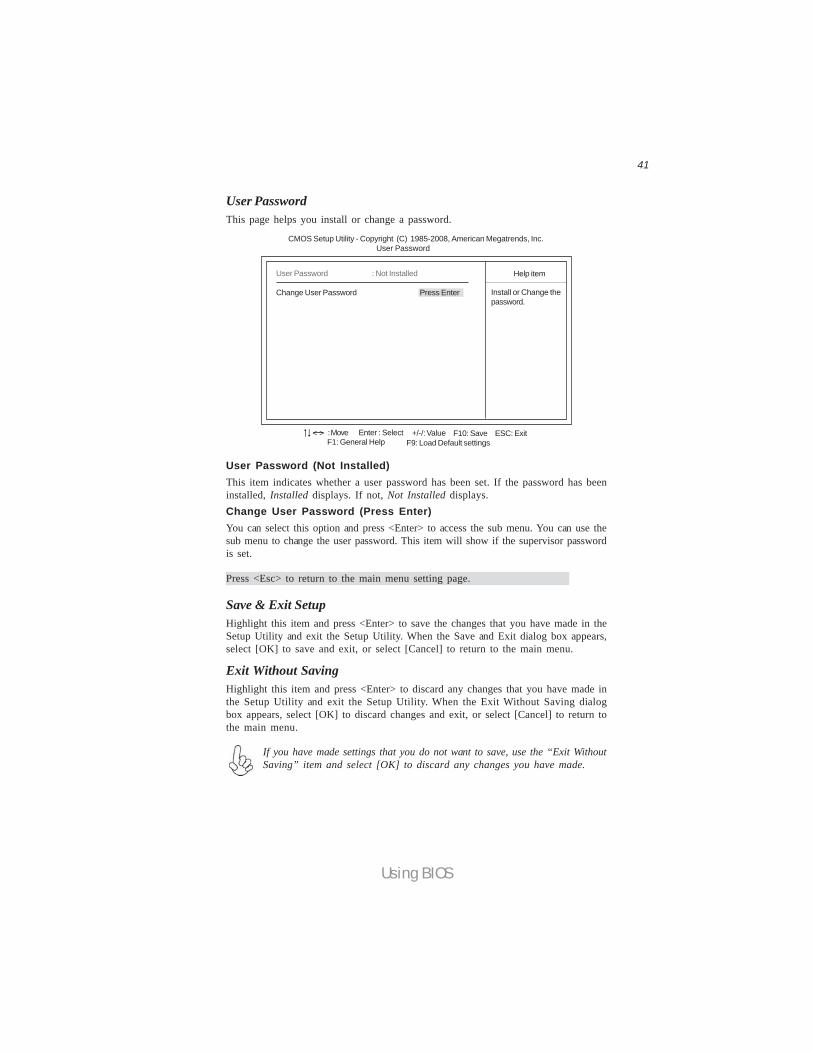
User Password (Not Installed)This item indicates whether a user password has been set. If the password has beeninstalled, Installed displays. If not, Not Installed displays.Change User Password (Press Enter)You can select this option and press <Enter> to access the sub menu. You can use thesub menu to change the user password. This item will show if the supervisor passwordis set.
User PasswordThis page helps you install or change a password.
Install or Change thepassword.
Help item
CMOS Setup Utility - Copyright (C) 1985-2008, American Megatrends, Inc. User Password
Press <Esc> to return to the main menu setting page.
User Password : Not Installed
Change User Password Press Enter
If you have made settings that you do not want to save, use the “Exit WithoutSaving” item and select [OK] to discard any changes you have made.
: Move F10: Save ESC: ExitEnter : Select +/-/: ValueF9: Load Default settingsF1: General Help
< >

42
Using BIOS
This concludes Chapter 3. Refer to the next chapter for information on the softwaresupplied with the motherboard.
1 If your motherboard has a BIOS protection jumper, change the setting toallow BIOS flashing.
2 If your motherboard has an item called Firmware Write Protect in Ad-vanced BIOS features, disable it. (Firmware Write Protect preventsBIOS from being overwritten.)
3 Create a bootable system disk. (Refer to Windows online help forinformation on creating a bootable system disk.)
4 Download the Flash Utility and new BIOS file from the manufacturer’sWeb site. Copy these files to the bootable device.
5 Turn off your computer and insert the bootable device in your com-puter. (You might need to run the Setup Utility and change the bootpriority items on the Advanced BIOS Features Setup page, to forceyour computer to boot from the bootable device first.)
6 At the C:\ or A:\ prompt, type the Flash Utility program name and the filename of the new bios and then press <Enter>. Example: AMINF340.EXE040706.ROM
7 When the installation is complete, remove the bootable device from thecomputer and restart your computer. If your motherboard has a FlashBIOS jumper, reset the jumper to protect the newly installed BIOS frombeing overwritten. The computer will restart automatically.
Updating the BIOSYou can download and install updated BIOS for this motherboard from themanufacturer’s Web site. New BIOS provides support for new peripherals, improve-ments in performance, or fixes for known bugs. Install new BIOS as follows:
43
Using the Motherboard Software
Chapter 4Using the Motherboard Software
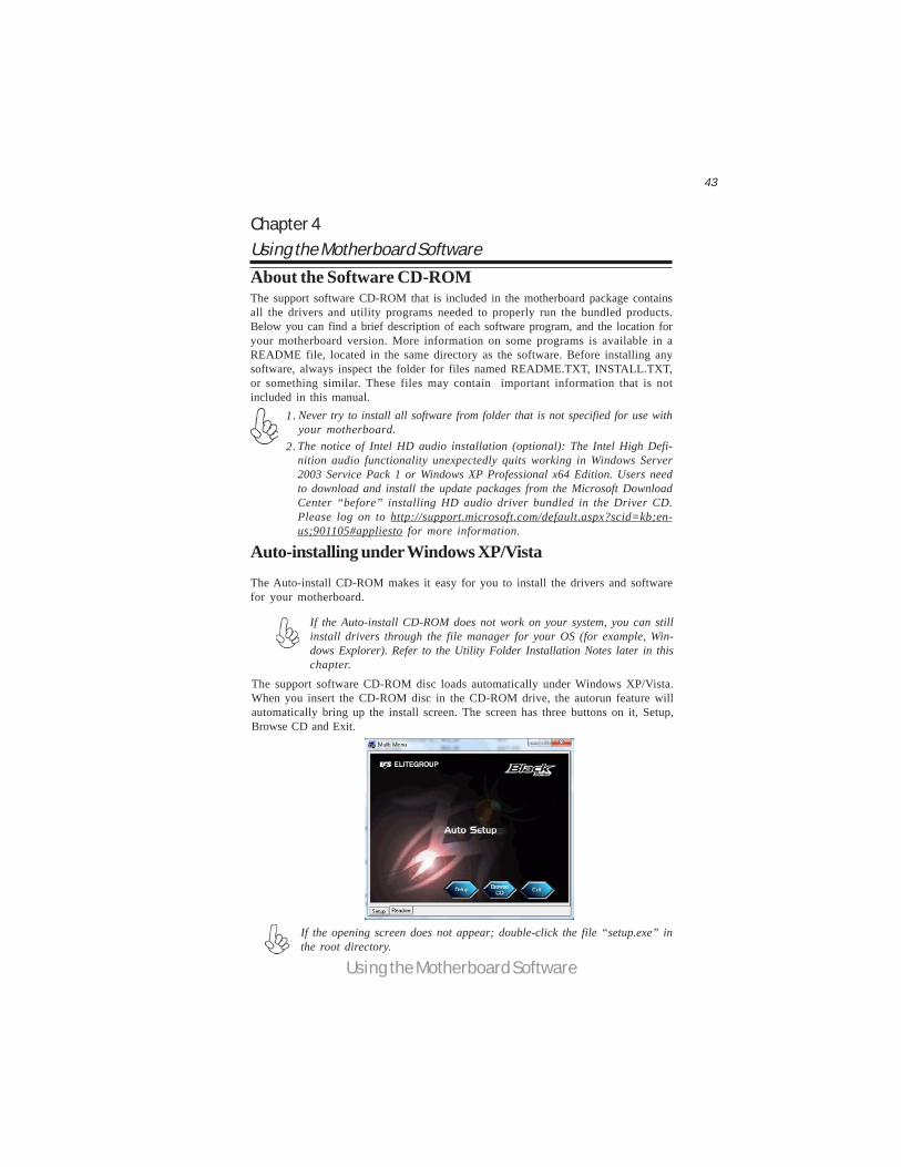
If the opening screen does not appear; double-click the file “setup.exe” inthe root directory.
About the Software CD-ROMThe support software CD-ROM that is included in the motherboard package containsall the drivers and utility programs needed to properly run the bundled products.Below you can find a brief description of each software program, and the location foryour motherboard version. More information on some programs is available in aREADME file, located in the same directory as the software. Before installing anysoftware, always inspect the folder for files named README.TXT, INSTALL.TXT,or something similar. These files may contain important information that is notincluded in this manual.
Never try to install all software from folder that is not specified for use withyour motherboard.The notice of Intel HD audio installation (optional): The Intel High Defi-nition audio functionality unexpectedly quits working in Windows Server2003 Service Pack 1 or Windows XP Professional x64 Edition. Users needto download and install the update packages from the Microsoft DownloadCenter “before” installing HD audio driver bundled in the Driver CD.Please log on to http://support.microsoft.com/default.aspx?scid=kb;en-us;901105#appliesto for more information.
1.
2.
Auto-installing under Windows XP/VistaThe Auto-install CD-ROM makes it easy for you to install the drivers and softwarefor your motherboard.
The support software CD-ROM disc loads automatically under Windows XP/Vista.When you insert the CD-ROM disc in the CD-ROM drive, the autorun feature willautomatically bring up the install screen. The screen has three buttons on it, Setup,Browse CD and Exit.
If the Auto-install CD-ROM does not work on your system, you can stillinstall drivers through the file manager for your OS (for example, Win-dows Explorer). Refer to the Utility Folder Installation Notes later in thischapter.
44
Using the Motherboard Software
Setup Tab
Setup Click the Setup button to run the software installation program.Select from the menu which software you want to install.
Browse CD
Exit The EXIT button closes the Auto Setup window.
Application TabLists the software utilities that are available on the CD.
Read Me TabDisplays the path for all software and drivers available on the CD.
Running SetupFollow these instructions to install device drivers and software for the motherboard:
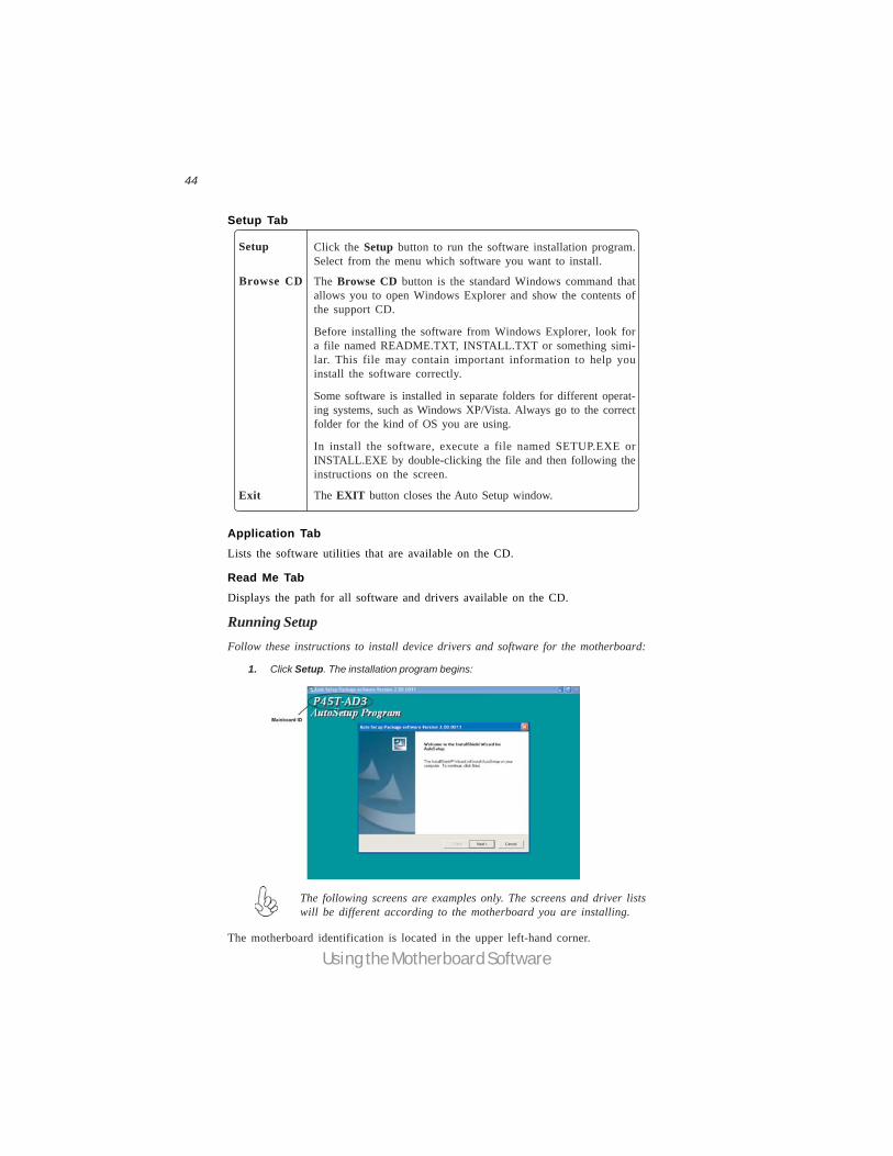
1. Click Setup. The installation program begins:
The following screens are examples only. The screens and driver listswill be different according to the motherboard you are installing.
The motherboard identification is located in the upper left-hand corner.
The Browse CD button is the standard Windows command thatallows you to open Windows Explorer and show the contents ofthe support CD.
Before installing the software from Windows Explorer, look fora file named README.TXT, INSTALL.TXT or something simi-lar. This file may contain important information to help youinstall the software correctly.
Some software is installed in separate folders for different operat-ing systems, such as Windows XP/Vista. Always go to the correctfolder for the kind of OS you are using.
In install the software, execute a file named SETUP.EXE orINSTALL.EXE by double-clicking the file and then following theinstructions on the screen.
45
Using the Motherboard Software
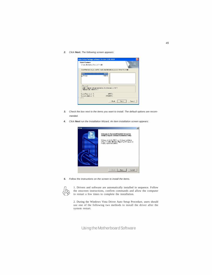
2. Click Next. The following screen appears:
3. Check the box next to the items you want to install. The default options are recom-
4. Click Next run the Installation Wizard. An item installation screen appears:
5. Follow the instructions on the screen to install the items.
1. Drivers and software are automatically installed in sequence. Followthe onscreen instructions, confirm commands and allow the computerto restart a few times to complete the installation.
2. During the Windows Vista Driver Auto Setup Procedure, users shoulduse one of the following two methods to install the driver after thesystem restart.
mended.

46
Using the Motherboard Software
Method 1. Run Reboot Setup
Windows Vista will block startup programs by default when installing drivers after thesystem restart. You must select taskbar icon Run Blocked Program and run RebootSetup to install the next driver, until you finish all drivers installation.
Method 2. Disable UAC (User Account Control)* For administrator account only. Standard user account can only use Method 1.
Disable Vista UAC function before installing drivers, then use CD driver to installdrivers, it will continue to install drivers after system restart without running blockedprograms.
Follow these instructions to Disable Vista UAC function:
1. Go to Control Panel.
47
Using the Motherboard Software
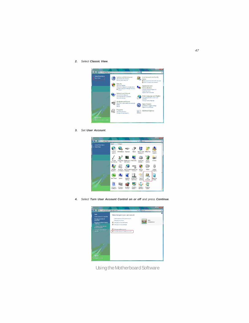
2. Select Classic View.
3. Set User Account.
4. Select Turn User Account Control on or off and press Continue.
48
Using the Motherboard Software
Manual InstallationInsert the CD in the CD-ROM drive and locate the PATH.DOC file in the rootdirectory. This file contains the information needed to locate the drivers for yourmotherboard.
Look for the chipset and motherboard model; then browse to the directory and pathto begin installing the drivers. Most drivers have a setup program (SETUP.EXE) thatautomatically detects your operating system before installation. Other drivers havethe setup program located in the operating system subfolder.
If the driver you want to install does not have a setup program, browse to theoperating system subfolder and locate the readme text file (README.TXT orREADME.DOC) for information on installing the driver or software for your oper-ating system.
Utility Software ReferenceAll the utility software available from this page is Windows compliant. They areprovided only for the convenience of the customer. The following software is fur-nished under license and may only be used or copied in accordance with the terms ofthe license.
These software(s) are subject to change at anytime without prior notice.Please refer to the support CD for available software.
This concludes chapter 4.
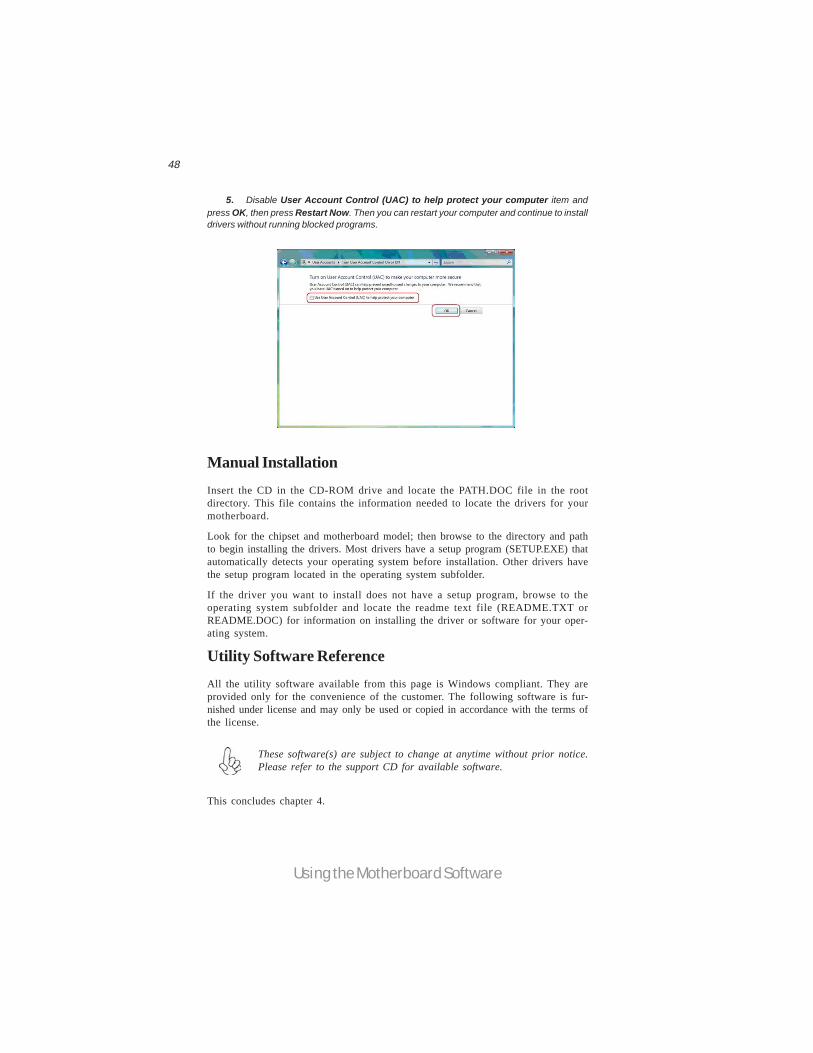
5. Disable User Account Control (UAC) to help protect your computer item andpress OK, then press Restart Now. Then you can restart your computer and continue to installdrivers without running blocked programs.
49
ATI CrossFireXTM Technology Support
Chapter 5ATI CrossFireXTM Technology SupportThis motherboard supports the ATI CrossFireXTM Technology that allows you toinstall multi-graphics processing units (GPU) graphics cards. Follow the installationprocedures in this section.
Requirements1 You should have a CrossFireXTM Ready motherboard, a CrossFireXTM Edi-
tion graphics card and a CrossFireXTM ready graphics card.2 Visit the ECS website (www.ecs.com.tw) for a list of qualified CrossFireXTM
ready graphics card for this motherboard.3 Make sure that your graphics card driver supports the ATI CrossFireXTM
technology. Download the latest driver from the ATI website(www.ati.com).
4 Make sure that your power supply unit (PSU) can provide at least theminimum power required by your system.
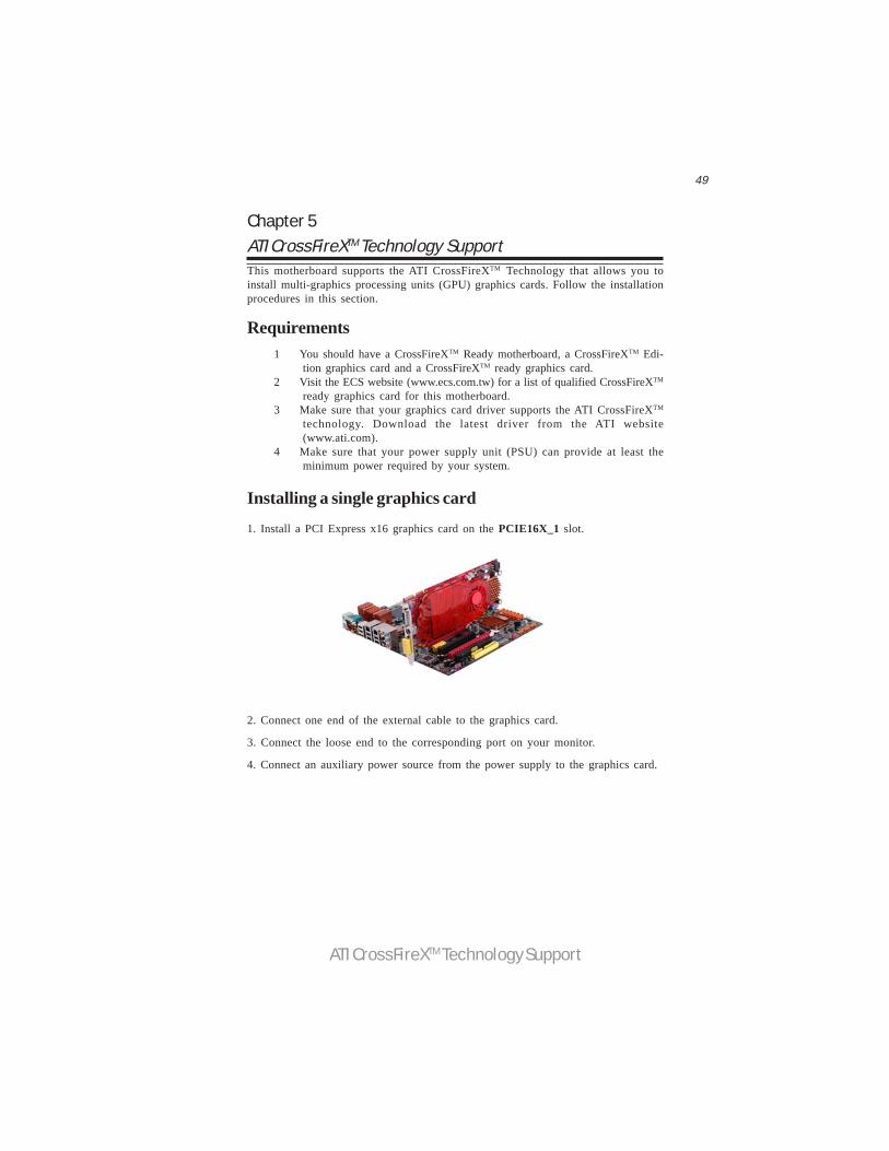
Installing a single graphics card1. Install a PCI Express x16 graphics card on the PCIE16X_1 slot.
2. Connect one end of the external cable to the graphics card.
3. Connect the loose end to the corresponding port on your monitor.
4. Connect an auxiliary power source from the power supply to the graphics card.

50
ATI CrossFireXTM Technology Support
Installing CrossFireXTM graphics cards1. Insert the CrossFireXTM graphics cards into the PCIE16X_1 and PCIE16X_2 slots.Make sure that the card is properly seated on the slot.
3. Connect the two CrossFireXTM Edition graphics cards installed on PCIE16X_1 andPCIE16X_2 slots with the CrossFire Bridge.
5. Connect an auxiliary power source from the power supply to the graphics cards.
2. Connect an external cable to the CrossFireXTM ready graphics card installed on thePCIE16X_2 slot.
External Cable
4. Connect the external cable to the corresponding port on your monitor.
51
ATI CrossFireXTM Technology Support
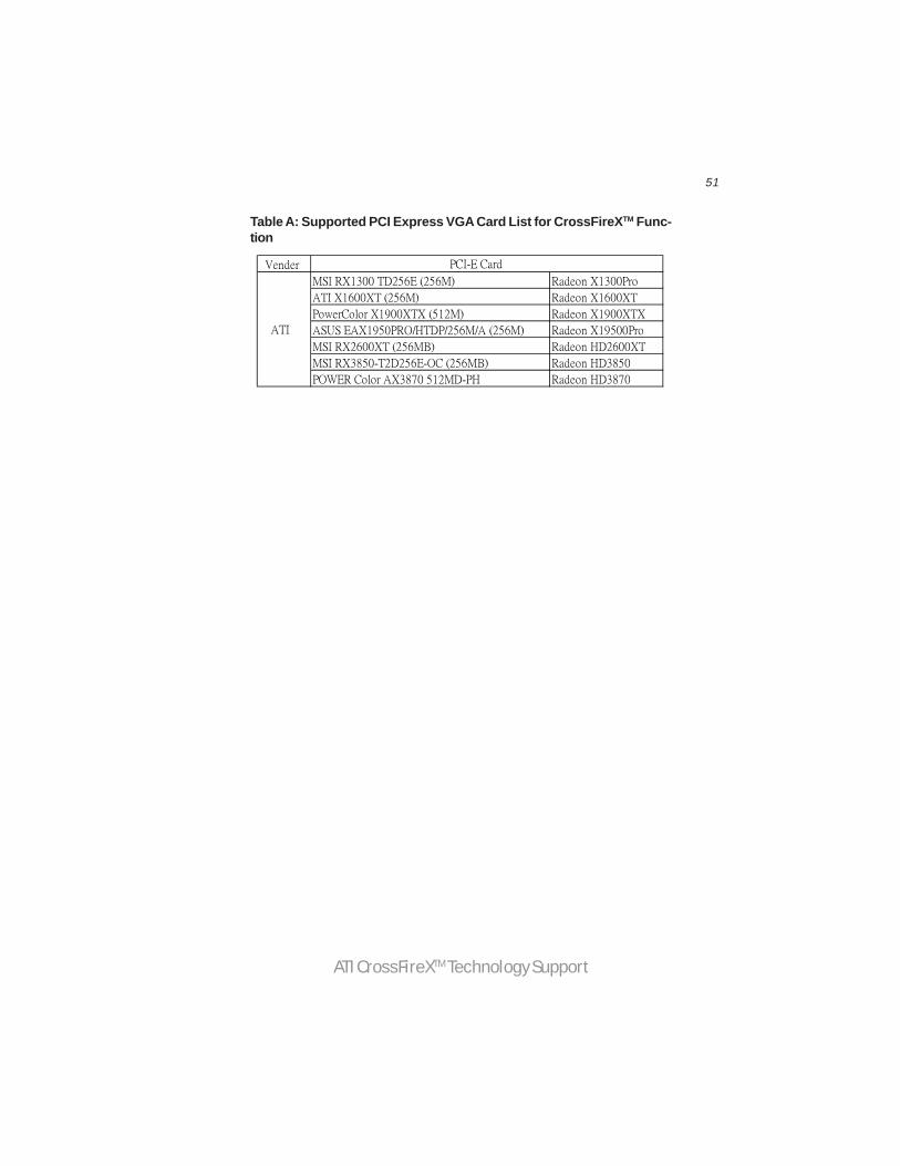
Table A: Supported PCI Express VGA Card List for CrossFireXTM Func-tion
Vender
MSI RX1300 TD256E (256M) Radeon X1300Pro
ATI X1600XT (256M) Radeon X1600XT
PowerColor X1900XTX (512M) Radeon X1900XTX
ASUS EAX1950PRO/HTDP/256M/A (256M) Radeon X19500Pro
MSI RX2600XT (256MB) Radeon HD2600XT
MSI RX3850-T2D256E-OC (256MB) Radeon HD3850
POWER Color AX3870 512MD-PH Radeon HD3870
ATI
PCI-E Card
52
ATI CrossFireXTM Technology Support
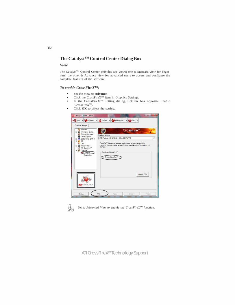
The CatalystTM Control Center Dialog BoxViewThe CatalystTM Control Center provides two views; one is Standard view for begin-ners, the other is Advance view for advanced users to access and configure thecomplete features of the software.
Set to Advanced View to enable the CrossFireXTM function.
To enable CrossFireXTM:• Set the view to Advance.• Click the CrossFireXTM item in Graphics Settings.• In the CrossFireXTM Setting dialog, tick the box opposite Enable
CrossFireXTM.• Click OK to effect the setting.
53
Intel® Matrix Storage Manager RAID Configurations
The Intel® Matrix Storage Manager allows you to configure RAID 0, and 1 sets on theexternal Serial ATA hard disk drives.
Complete the following steps before you create a RAID set:
1. Install the external Serial ATA hard disk drive (HDD) on your system.
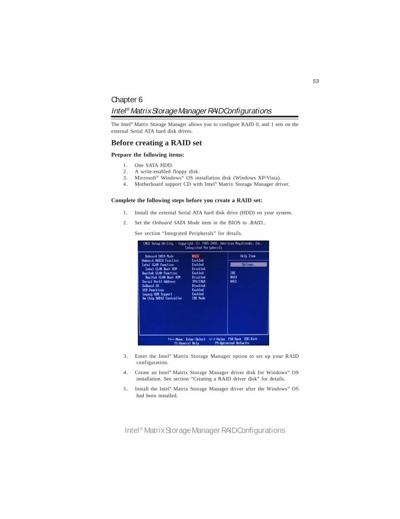
2. Set the Onboard SATA Mode item in the BIOS to .RAID..
See section “Integrated Peripherals” for details.
Before creating a RAID setPrepare the following items:
1. One SATA HDD.2. A write-enabled floppy disk.3. Microsoft® Windows® OS installation disk (Windows XP/Vista).4. Motherboard support CD with Intel® Matrix Storage Manager driver.
Chapter 6Intel® Matrix Storage Manager RAID Configurations
3. Enter the Intel® Matrix Storage Manager option to set up your RAIDconfiguration.
4. Create an Intel® Matrix Storage Manager driver disk for Windows® OSinstallation. See section “Creating a RAID driver disk” for details.
5. Install the Intel® Matrix Storage Manager driver after the Windows® OShad been installed.
54
Intel® Matrix Storage Manager RAID Configurations
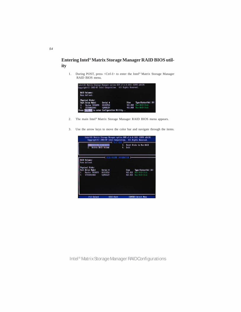
2. The main Intel® Matrix Storage Manager RAID BIOS menu appears.
Entering Intel® Matrix Storage Manager RAID BIOS util-ity
1. During POST, press <Ctrl-I> to enter the Intel® Matrix Storage ManagerRAID BIOS menu.
3. Use the arrow keys to move the color bar and navigate through the items.
55
Intel® Matrix Storage Manager RAID Configurations
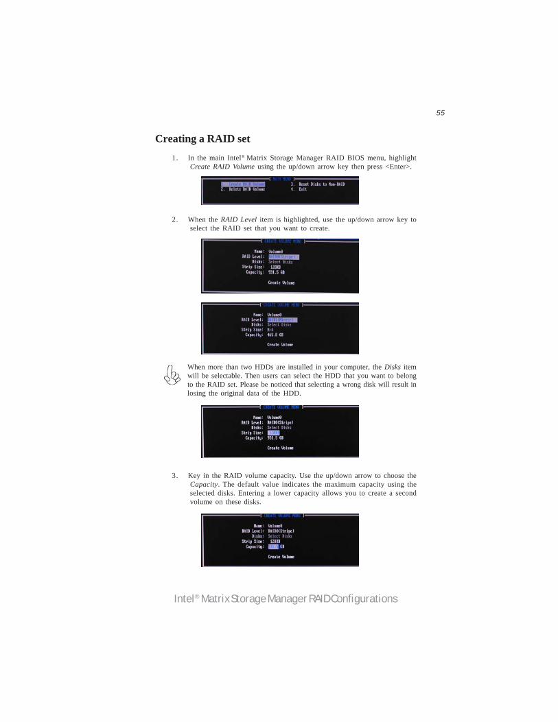
2. When the RAID Level item is highlighted, use the up/down arrow key toselect the RAID set that you want to create.
Creating a RAID set1. In the main Intel® Matrix Storage Manager RAID BIOS menu, highlight
Create RAID Volume using the up/down arrow key then press <Enter>.
3. Key in the RAID volume capacity. Use the up/down arrow to choose theCapacity. The default value indicates the maximum capacity using theselected disks. Entering a lower capacity allows you to create a secondvolume on these disks.
When more than two HDDs are installed in your computer, the Disks itemwill be selectable. Then users can select the HDD that you want to belongto the RAID set. Please be noticed that selecting a wrong disk will result inlosing the original data of the HDD.
56
Intel® Matrix Storage Manager RAID Configurations
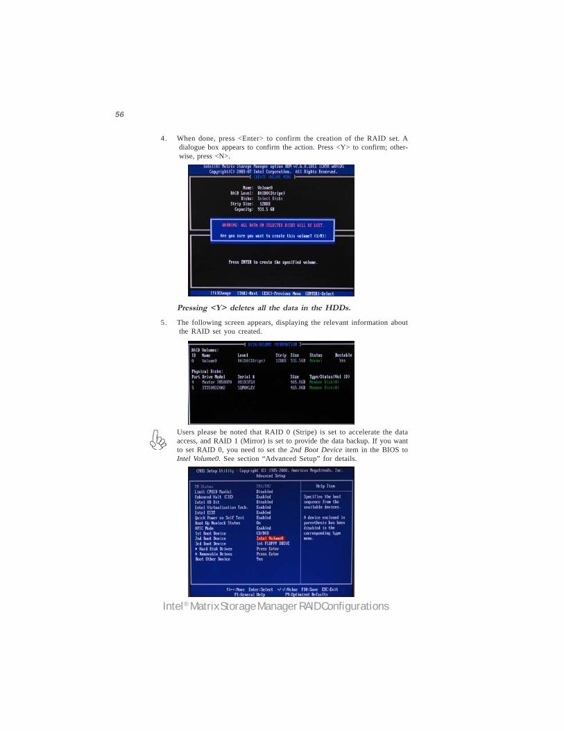
Pressing <Y> deletes all the data in the HDDs.5. The following screen appears, displaying the relevant information about
the RAID set you created.
Users please be noted that RAID 0 (Stripe) is set to accelerate the dataaccess, and RAID 1 (Mirror) is set to provide the data backup. If you wantto set RAID 0, you need to set the 2nd Boot Device item in the BIOS toIntel Volume0. See section “Advanced Setup” for details.
4. When done, press <Enter> to confirm the creation of the RAID set. Adialogue box appears to confirm the action. Press <Y> to confirm; other-wise, press <N>.

57
Intel® Matrix Storage Manager RAID Configurations
Deleting a RAID set1. In the main Intel® Matrix Storage Manager RAID BIOS menu, highlight
Delete RAID Volume using the up/down arrow key then press <Enter>.
2. Use the space bar to select the RAID set you want to delete.
Press the <Del> key to delete the set.
3. A dialogue box appears to confirm the action. Press <Y> to confirm;otherwise, press <N>.
Pressing <Y> deletes all the data in the HDDs.
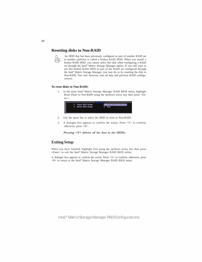
58
Intel® Matrix Storage Manager RAID Configurations
Resetting disks to Non-RAID An HDD that has been previously configured as part of another RAID setin another platform is called a broken RAID HDD. When you install abroken RAID HDD, you cannot select this disk when configuring a RAIDset through the Intel® Matrix Storage Manager option. If you still want touse this broken RAID HDD as part of the RAID set configured throughthe Intel® Matrix Storage Manager, you may do so by resetting the disk toNon-RAID. You will, however, lose all data and previous RAID configu-rations.
To reset disks to Non-RAID:1. In the main Intel® Matrix Storage Manager RAID BIOS menu, highlight
Reset Disks to Non-RAID using the up/down arrow key then press <En-ter>.
2. Use the space bar to select the HDD to reset to Non-RAID.
3. A dialogue box appears to confirm the action. Press <Y> to confirm;otherwise, press <N>.
Pressing <Y> deletes all the data in the HDDs.
Exiting SetupWhen you have finished, highlight Exit using the up/down arrow key then press<Enter> to exit the Intel® Matrix Storage Manager RAID BIOS utility.
A dialogue box appears to confirm the action. Press <Y> to confirm; otherwise, press<N> to return to the Intel® Matrix Storage Manager RAID BIOS menu.