Embed Size (px)
Citation preview
TECHNICAL BULLETIN 1000HP-BASIC-TB09-17
Streamlined Flow Path:
High InletPressures:
High Outlet Pressures:
High Pressure Drop:
Flow-to-Open Plug:
Versatility:
ProtectedDiaphragm
Zone:
Diaphragm Travel Stops:
Straight-through flow path reduces internal tur bu lence and resistance to flow, in creas- ing stability and capacity.
Standard construction allows inlet pres- sures up to 740 psig (51.0 Barg).
Controlled outlet pressure up to 300 psig (20.7 Barg).
Standard construction with extended guid- ing allows pressure drop up to 650 psid (44.8 Bard). This regulator is routinely ap plied in severe service conditions.
Provides unmatched rangeability – far great er than com pet i tive flow-to-close de signs. Highly stable at either high or low flow rates.
Four body materials and nineteen trim ma-terial selections allow us age in a mul ti tude of various fluids. Optional con struc tions ex tend the ca pa bil i ty.
Internal arrangement isolates the di a- phragm from direct impingement, ne gat ing any flow induced instability at either low or high flow rates. Allows incorporation of dy nam ic boost from jet section. Uniformly registers pres sure on the diaphragm.
Incorporates mechanical stop in spring cham ber to limit diaphragm uptravel and in body for downtravel, minimizing po-tential in ter nal damage from over-travel con di tions.
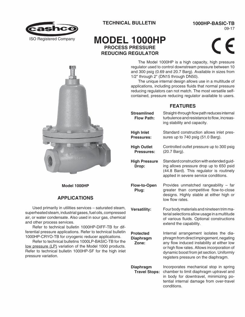
The Model 1000HP is a high capacity, high pressure reg u la tor used to control downstream pressure between 10 and 300 psig (0.69 and 20.7 Barg). Available in sizes from 1/2" through 2" (DN15 through DN50).
The unique internal design allows use in a mul ti tude of applications, including process fluids that normal pres sure reducing regulators can not match. The most versatile self-contained, pressure reducing regulator available to users.
FEATURES
APPLICATIONS
Used primarily in utilities services – sat u rat ed steam, superheated steam, industrial gases, fuel oils, com pressed air, or water condensate. Also used in sour gas, chemical and other process services.
Refer to technical bulletin 1000HP-DIFF-TB for dif- fer en tial pressure applications. Refer to technical bulletin 1000HP-CRYO-TB for cryogenic reducer ap pli ca tions.
Refer to technical bulletins 1000LP-BASIC-TB for the low pressure (LP) variation of the Model 1000 products. Refer to technical bulletin 1000HP-SF for the high inlet pressure variation.
Model 1000HP
MODEL 1000HPPROCESS PRESSURE
REDUCING REG U LA TOR
ISO Registered Company
2 1000HP-BASIC-TB
1/2", 3/4", 1", 1-1/4", 1-1/2" and 2" (DN15, 20, 25, 32, 40 and 50).
Standard – NPT female.Opt-30: 150# or 300# RF flanged.Opt-31: BSPT Tapered Thread.Opt-31P: BSPP Parallel Thread.Opt-32: Ex tend ed plain end nip ples.Opt-34: 14" Face to Face Flange Dim. (Sizes 1/2"- 1"& 1-1/2" only)
Uniform – DI/DI, BRZ/BRZ, CS/CS and SST/SST.Combinations – CS/DI, BRZ/DI,SST/DI and SST/CS.
DI = Ductile iron CS = Cast carbon steel BRZ = Cast bronze SST = Cast stainless steelSee Table 5 for material spec i fi ca- tions.NOTE: 1-1/4" (DN32) SST or BRZ bod ies not avail able.
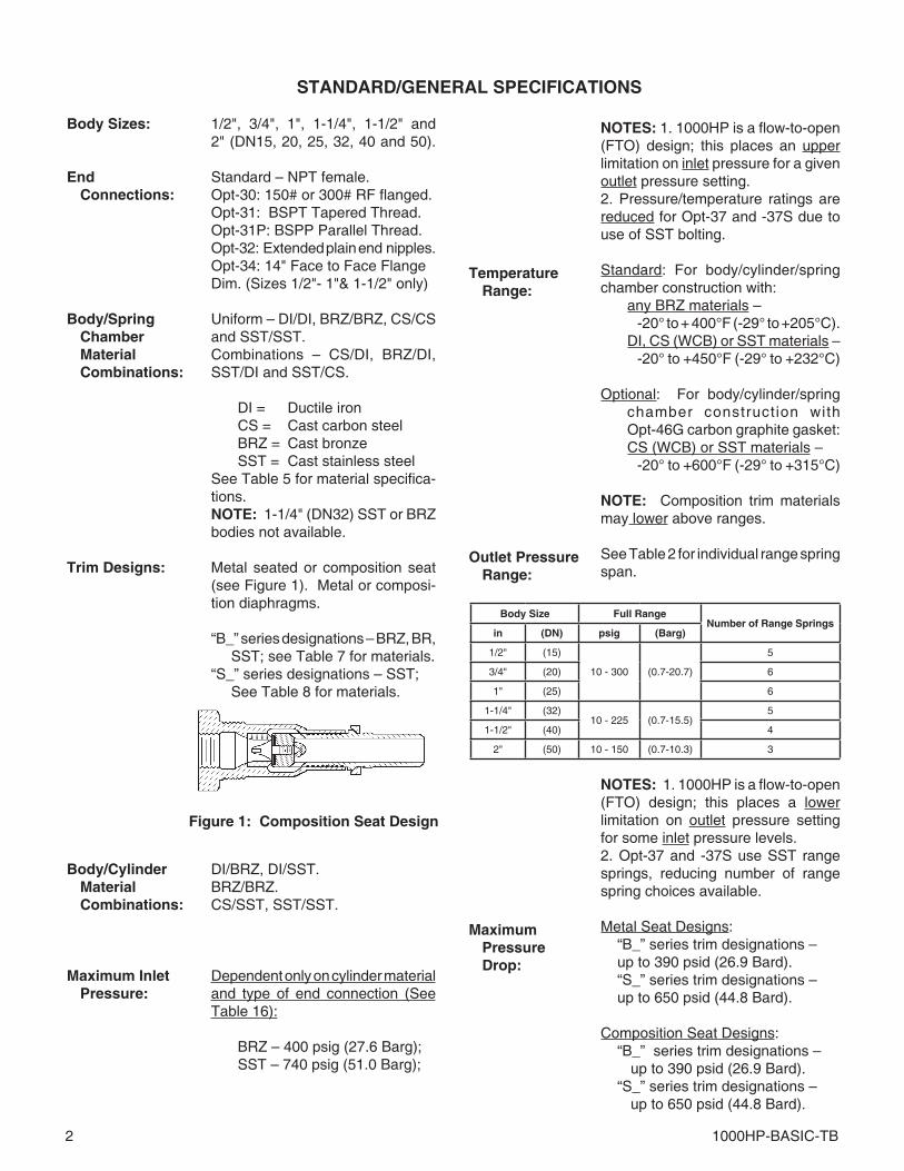
Metal seated or com po si tion seat (see Figure 1). Metal or com po si- tion di a phragms.
“B_” series designations – BRZ, BR, SST; see Table 7 for materials.
“S_” series designations – SST; See Table 8 for materials.
DI/BRZ, DI/SST.BRZ/BRZ.CS/SST, SST/SST.
Dependent only on cylinder material and type of end connection (SeeTable 16):
BRZ – 400 psig (27.6 Barg); SST – 740 psig (51.0 Barg);
STANDARD/GENERAL SPECIFICATIONS
Body Sizes:
EndConnections:
Body/Spring Chamber
MaterialCombinations:
Trim Designs:
Body/Cylinder MaterialCombinations:
Maximum Inlet Pressure:
NOTES: 1. 1000HP is a flow-to-open (FTO) design; this plac es an upper lim i ta tion on inlet pressure for a given outlet pressure setting.2. Pressure/tem per a ture ratings are re duced for Opt-37 and -37S due to use of SST bolting.
Standard: For body/cylinder/spring chamber construction with: any BRZ materials – -20° to + 400°F (-29° to +205°C). DI, CS (WCB) or SST materials – -20° to +450°F (-29° to +232°C) Optional: For body/cylinder/spring
chamber construction withOpt-46G carbon graphite gasket:
CS (WCB) or SST materials – -20° to +600°F (-29° to +315°C)
NOTE: Composition trim materials may lower above ranges.
See Table 2 for individual range spring span.
NOTES: 1. 1000HP is a flow-to-open (FTO) design; this plac es a low er lim i ta tion on outlet pres sure set ting for some inlet pres sure levels.2. Opt-37 and -37S use SST range springs, reducing num ber of range spring choices available.
Metal Seat Designs: “B_” series trim designations – up to 390 psid (26.9 Bard). “S_” series trim designations – up to 650 psid (44.8 Bard).
Composition Seat Designs: “B_” series trim des ig na tions – up to 390 psid (26.9 Bard). “S_” series trim designations – up to 650 psid (44.8 Bard).
Temperature Range:
Outlet Pressure Range:
MaximumPressure Drop:
Body Size Full RangeNumber of Range Springs
in (DN) psig (Barg)
1/2" (15)
10 - 300 (0.7-20.7)
5
3/4" (20) 6
1" (25) 6
1-1/4" (32)10 - 225 (0.7-15.5)
5
1-1/2" (40) 4
2" (50) 10 - 150 (0.7-10.3) 3
Figure 1: Composition Seat Design
1000HP-BASIC-TB 3
Standard: ∆P > 5 psid (0.34 Bard)Opt-17: ∆P ≤ 1-5 psid (0.07-0.34 Bard) Minimum = 1 psid (0.07 Bard).
Meets ANSI/FCI 70-2. Metal Seated – Class IV. Composition Seat – Class VI.
See Tables 9 through 12 for flow ca- pac i ty expressed in Cv’s for full port and 1-step reduced port (Opt-12).
See Table 3 for “Wide Open Cv”; use for sizing of safety relief device.
Standard: Heat treated steel, zincplated.Opt-37 and -37S: SST.
Standard: High strength, zinc plated, heat treat ed steel.Opt-37 and -37S: SST.
MinimumPressure Drop:
Seat Leakage:
Range Springs
Diaphragm Flange Bolting:
Gaskets:
Painting:
Required for metal diaphragm con struc tions only; not re quired for com po si tion diaphragm con struc tion. Standard: Graphite/NBR.(Not suitable for oxygen service.) Tmax = 450°F (232°C) Opt-45: Alternate TFE gaskets
primarily for ox y gen service. Tmax = 400°F (205°C). Opt-46G: Alternate carbon graph-
ite gaskets. Tmax = 600°F (315°C).
Standard All non-corrosion resistantportions to be painted with corrosion resistant epoxy paint per Cashco Spec #S-1606.
Alternate: See Opt-95 or -95OS.
OPTION SPECIFICATIONS
Option -1:
Option -1+6:Option -1+8:
Option -3:
Option -5:
Option -12:
Option -14:
CLOSING CAP. A removable ductile iron cap dis cour ag es tampering with spring setting. Available only with DI or CS spring chamber materials. In cludes a gasket for sealing the closing cap to the spring chamber, a sealing lock nut and a 1/4" NPT female vent connection.
DIFFERENTIAL CON STRUC TION. Refer to Tech ni cal Bulletin 1000HP-DIFF-TB for technical information for dif fer en tial pressure ap pli ca tions.
MANUAL ADJUSTOR AND LOCK ING LEVER. Use when frequent spring range settings are required. For sizes 1/2", 3/4" and 1" (DN15, 20 and 25) adjusting screw has handwheel fixed to end, and locking nut is re placed by a locking lever that is easily loosened/tightened. For sizes 1-1/4", 1-1/2" and 2" (DN32, 40, 50) handwheel is re placed by T-bar adjustor.
BRZ/BR CRYOGENIC CON STRUC- TION. Refer to Tech ni cal Bulletin 1000HP-CRYO-TB for technical in- for ma tion for cryogenic applications.
REDUCED PORT ORIFICE. Used when high inlet pressure ne gates use of the stan dard full port orifice. Also used when over sized body is desired to ac com mo date pip ing size. Avail- able in metal seated or composition seat materials, in all “B_” or “S_” se ries trim des ig na tions, and in all body sizes except 1-1/4" (DN32). See Ta bles 10 and 12 for flow ca pac i ty in Cv’s.
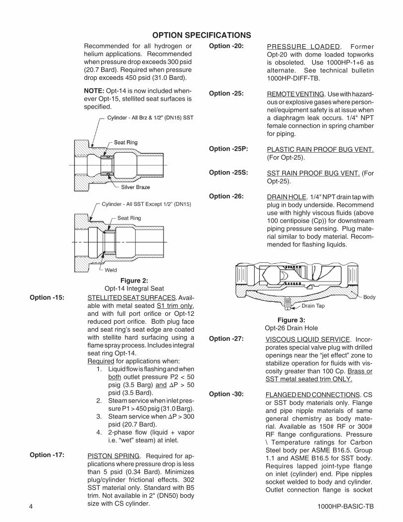
INTEGRAL SEAT. Standard pressed-in seat ring-to-cyl in der joint is sealed as a path of leakage by brazing or weld ing. The procedure also serves as a per-manent joint for flow con di tions where service conditions are “se vere”, subject to vibration, or thermal cycling.
Seat ring is silver brazed to cylinder for all “B_” series composition trim designa-tions, and to 1/2" (DN15) body size cyl-inders with “S_” series trim designations. For all other body sizes with “S_” seriesdesignations the seat ring is welded to the cylinder.
4 1000HP-BASIC-TB
OPTION SPECIFICATIONSRecommended for all hydrogen or helium applications. Recommended when pres sure drop exceeds 300 psid (20.7 Bard). Required when pressure drop exceeds 450 psid (31.0 Bard).
NOTE: Opt-14 is now included when- ev er Opt-15, stellited seat surfaces is specified.
Option -15:
PRESSURE LOADED. FormerOpt-20 with dome loaded topworks is ob so let ed. Use 1000HP-1+6 as al ter nate. See technical bulletin1000HP-DIFF-TB.
REMOTE VENTING. Use with haz ard- ous or explosive gases where per son- nel/equipment safety is at issue when a diaphragm leak occurs. 1/4" NPT female con nec tion in spring cham ber for piping.
PLASTIC RAIN PROOF BUG VENT. (For Opt-25).
SST RAIN PROOF BUG VENT. (For Opt-25).
DRAIN HOLE. 1/4" NPT drain tap with plug in body underside. Rec om mend use with highly viscous fluids (above 100 centipoise (Cp)) for down stream piping pres sure sensing. Plug mate-rial similar to body material. Rec om- mend ed for flashing liquids.
STELLITED SEAT SURFACES. Avail- able with metal seat ed S1 trim only, and with full port orifice or Opt-12reduced port orifice. Both plug face and seat ring’s seat edge are coated with stellite hard surfacing us ing a flame spray process. Includes integral seat ring Opt-14. Required for applications when: 1. Liquid flow is flash ing and when
both out let pressure P2 < 50 psig (3.5 Barg) and ∆P > 50 psid (3.5 Bard).
2. Steam service when inlet pres- sure P1 > 450 psig (31.0 Barg).
3. Steam service when ∆P > 300 psid (20.7 Bard).
4. 2-phase flow (liquid + vapor i.e. “wet” steam) at inlet.
PISTON SPRING. Required for ap- pli ca tions where pres sure drop is less than 5 psid (0.34 Bard). Minimizes plug/cylinder frictional effects. 302 SST material only. Standard with B5 trim. Not avail able in 2" (DN50) body size with CS cylinder.
Figure 2:Opt-14 Integral Seat
Option -20:
Option -25:
Option -25P:
Option -25S:
Option -26:
Option -27:
Option -30:
VISCOUS LIQUID SERVICE. In cor- po rates special valve plug with drilled openings near the “jet effect” zone to stabilize operation for fluids with vis- cos i ty greater than 100 Cp. Brass or SST metal seated trim ONLY.
FLANGED END CONNECTIONS. CS or SST body ma te ri als only. Flange and pipe nipple materials of same gen er al chemistry as body mate-rial. Avail able as 150# RF or 300# RF flange configurations. Pressure \ Temperature ratings for Carbon Steel body per ASME B16.5. Group 1.1 and ASME B16.5 for SST body. Requires lapped joint-type flange on inlet (cyl in der) end. Pipe nipples socket weld ed to body and cylinder. Outlet connection flange is socket
Figure 3:Opt-26 Drain Hole
Option -17:
1000HP-BASIC-TB 5
ALL SST/CLEAN UNIT FOR STEAM. Similar to Option -37, except is equipped with different trim; use with S1 trim ONLY. Includes carbon graph ite diaphragm gasket material. In cludes Opt-26 1/4" NPT tap with SST plug.Use of SST flange bolting limitsP vs T ratings to levels below stan dard unit (see Table 16). Also limits pres- sure set tings to overall range of 10–80 psig (0.7–5.5 Barg) using multiple SST springs.
NACE CONSTRUCTION. Internal wetted portions meet NACE standard MR0175 for application in sour gas ser vice. Exterior of the unit to not be directly exposed to a sour gas en vi ron ment, buried, insulated or oth er wise denied direct atmospheric ex po sure. CS/CS or SST/CS body/spring cham ber materials ONLY. Ac- cept able ONLY with S40, S40V, S3, or S3N trims. Not avail able with Opt-14, Opt-15, Opt-17, or Opt-37.
TFE/SILICATE-GASKET. Primarily for oxygen ser vice. Lim its tempera-ture range to -20° to +400°F (-29° to +205°C). Not re quired when using a composition di a phragm.
HIGH TEMPERATURE GASKETS. CS (WCB) or SST body/spring cham-ber materials only with S1 or S2 trim. Uti liz es carbon graphite gaskets over stan dard gas kets. Primarily ap plied at tem per a tures over 400°F (205°C) or at cus tom er’s request; range of -20° to +600°F (-29° to +315°C).(See Table 8 a.1)
SPECIAL CLEANING. BRZ or SST body materials ONLY. Cleaning per Cashco Spec #S-1134 for Oxygen gas Service.NOTE: De sign Pressure Rating shall not exceed 375 psig (25.8 Barg) when body material is SST and process medium is oxygen.
SPECIAL CLEANING. Cleaning per Cashco Spec #S-1542. NOT suitable for Ox y gen Ser vice.
Option -31
Option -31P:
Option -32:
Option -34:
Option -36:
Option -37:
weld-type. See Table 16 for loweredP vs T rat ings. No post-weld stress re liev ing performed. Not avail able in 1-1/4" (DN32) body size. (Suitable for NACE service with post-weld, stress relief, heat treatment).
BSPT END CONNECTIONS. British Standard Tapered Pipe threads per ISO 7/1; used as alternate to NPT.
BSPP END CON NEC TIONS. British Stan dard Parallel Pipe threads per ISO 7/1; used as alternate to NPT ends.
EXTENDED P.E. NIPPLES. Sched ule 80 plain end pipe nipples used for field butt or socket welding into pipe line. Pipe nip ples of same general chem- is try as body material. Short-thread ed pipe nipples seal welded to body and cylinder. Adds ap prox i mate ly 8 inches (200 mm) to the face-to-face di men- sion of stan dard unit. Use for socket weld pipe systems. (Suitable for NACE service with post-weld, stress relief, heat treatment).
SPECIAL 14" FACE TO FACE DIMENSION FOR FLANGED END CON NEC TIONS. Sizes 1/2" - 1" & 1-1/2" only. See Opt.-30 for stan-dard face to face dimension.
SST CRYOGENIC CON STRUC TION. Refer to tech ni cal bulletin 1000HP-CRYO-TB for technical in for ma tion for cryogenic applications.
ALL SST/CLEAN UNIT FOR LIQ UIDS AND GASES. Packaged primarily for the food and pharmaceutical in dus- tries. NPT and 150# SST RF flanged end con nec tions ONLY. 316 SST body and spring cham ber ma te ri als ONLY. Use with S6 trim ONLY. T-bar handle, spring chamber internals, and flange bolting of SST materials. All wetted and ex ter nal cast ings are electro-pol ished, and the unit is cleaned to Cash co Spec. #S-1576. IncludesOpt-26 1/4" NPT tap with SST plug.
Use of SST diaphragm flange bolting lim its P vs T ratings to levels below standard unit (see Table 16). Also limits pressure settings to overall range of 10–80 psig (0.7–5.5 Barg) using mul ti ple SST springs.
Option -37S:
Option -40:
Option -45:
Option -46G:
Option -55:
Option -56:
6 1000HP-BASIC-TB
TWO 1/8" (DN6) NPT TAPS. One located on the inlet, one on the outlet for gauge connections for Opt-34 only.
EPOXY PAINT. Special epoxy paint- ing of all non-corrosion resistant external surfaces per Cashco Spec#S-1547. Utilized in harsh atmospheric conditions.
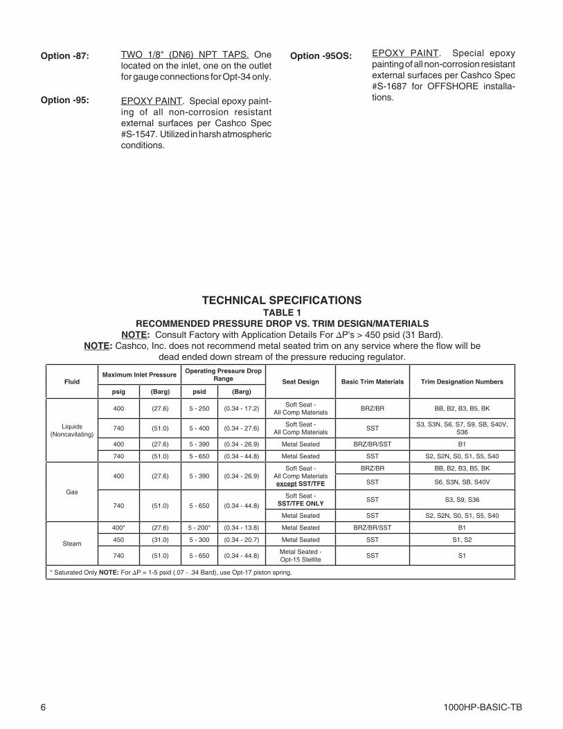
TECHNICAL SPECIFICATIONSTABLE 1
RECOMMENDED PRESSURE DROP VS. TRIM DESIGN/MATERIALSNOTE: Consult Factory with Application Details For ∆P's > 450 psid (31 Bard).
NOTE: Cashco, Inc. does not recommend metal seated trim on any service where the flow will bedead ended down stream of the pressure reducing regulator.
FluidMaximum Inlet Pressure
Operating Pressure Drop Range Seat Design Basic Trim Materials Trim Designation Numbers
psig (Barg) psid (Barg)
Liquids(Noncavitating)
400 (27.6) 5 - 250 (0.34 - 17.2)Soft Seat -
All Comp MaterialsBRZ/BR BB, B2, B3, B5, BK
740 (51.0) 5 - 400 (0.34 - 27.6)Soft Seat -
All Comp MaterialsSST
S3, S3N, S6, S7, S9, SB, S40V, S36
400 (27.6) 5 - 390 (0.34 - 26.9) Metal Seated BRZ/BR/SST B1
740 (51.0) 5 - 650 (0.34 - 44.8) Metal Seated SST S2, S2N, S0, S1, S5, S40
Gas
400 (27.6) 5 - 390 (0.34 - 26.9)Soft Seat -
All Comp Materialsexcept SST/TFE
BRZ/BR BB, B2, B3, B5, BK
SST S6, S3N, SB, S40V
740 (51.0) 5 - 650 (0.34 - 44.8)
Soft Seat -SST/TFE ONLY
SST S3, S9, S36
Metal Seated SST S2, S2N, S0, S1, S5, S40
Steam
400* (27.6) 5 - 200* (0.34 - 13.8) Metal Seated BRZ/BR/SST B1
450 (31.0) 5 - 300 (0.34 - 20.7) Metal Seated SST S1, S2
740 (51.0) 5 - 650 (0.34 - 44.8)Metal Seated -Opt-15 Stellite
SST S1
* Saturated Only NOTE: For ∆P = 1-5 psid (.07 - .34 Bard), use Opt-17 piston spring.
Option -87:
Option -95:
Option -95OS: EPOXY PAINT. Special epoxy paint ing of all non-corrosion resistant external surfaces per Cashco Spec#S-1687 for OFFSHORE installa-tions.
1000HP-BASIC-TB 7
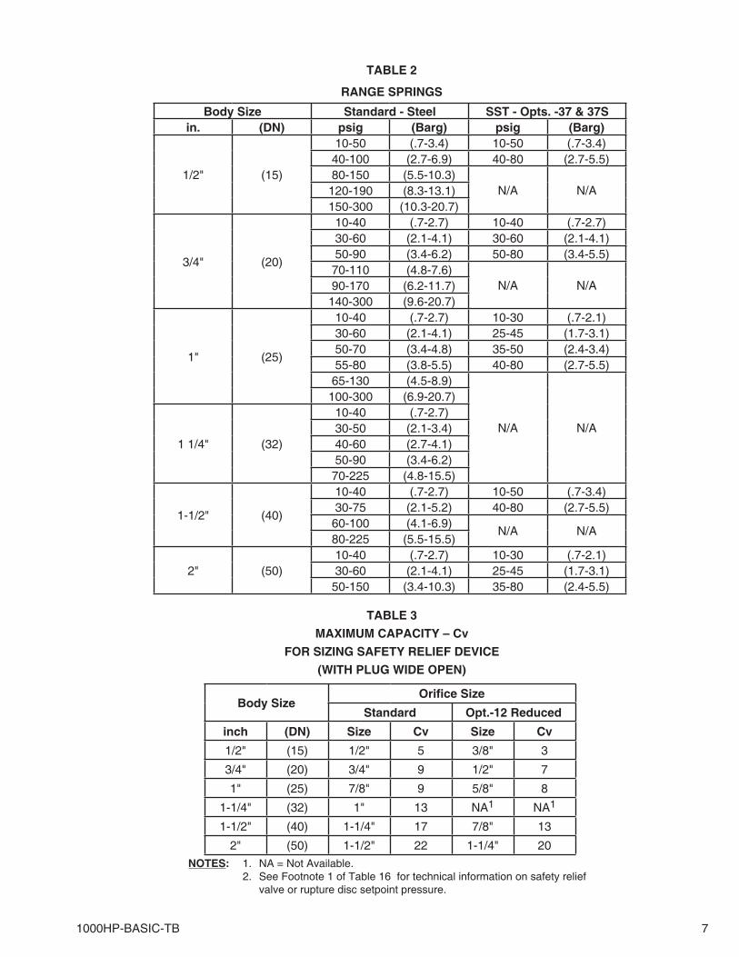
TABLE 2
RANGE SPRINGS
TABLE 3
MAXIMUM CAPACITY – Cv
FOR SIZING SAFETY RELIEF DEVICE
(WITH PLUG WIDE OPEN)
NOTES: 1. NA = Not Available. 2. See Footnote 1 of Table 16 for technical information on safety relief valve or rupture disc setpoint pressure.
Body SizeOrifi ce Size
Standard Opt.-12 Reduced
inch (DN) Size Cv Size Cv
1/2" (15) 1/2" 5 3/8" 3
3/4" (20) 3/4" 9 1/2" 7
1" (25) 7/8" 9 5/8" 8
1-1/4" (32) 1" 13 NA1 NA1
1-1/2" (40) 1-1/4" 17 7/8" 13
2" (50) 1-1/2" 22 1-1/4" 20
Body Size Standard - Steel SST - Opts. -37 & 37Sin. (DN) psig (Barg) psig (Barg)
1/2" (15)
10-50 (.7-3.4) 10-50 (.7-3.4)40-100 (2.7-6.9) 40-80 (2.7-5.5)80-150 (5.5-10.3)
N/A N/A120-190 (8.3-13.1)150-300 (10.3-20.7)
3/4" (20)
10-40 (.7-2.7) 10-40 (.7-2.7)30-60 (2.1-4.1) 30-60 (2.1-4.1)50-90 (3.4-6.2) 50-80 (3.4-5.5)
70-110 (4.8-7.6)N/A N/A90-170 (6.2-11.7)
140-300 (9.6-20.7)
1" (25)
10-40 (.7-2.7) 10-30 (.7-2.1)30-60 (2.1-4.1) 25-45 (1.7-3.1)50-70 (3.4-4.8) 35-50 (2.4-3.4)55-80 (3.8-5.5) 40-80 (2.7-5.5)
65-130 (4.5-8.9)
N/A N/A
100-300 (6.9-20.7)
1 1/4" (32)
10-40 (.7-2.7)30-50 (2.1-3.4)40-60 (2.7-4.1)50-90 (3.4-6.2)
70-225 (4.8-15.5)
1-1/2" (40)
10-40 (.7-2.7) 10-50 (.7-3.4)30-75 (2.1-5.2) 40-80 (2.7-5.5)
60-100 (4.1-6.9)N/A N/A
80-225 (5.5-15.5)
2" (50)10-40 (.7-2.7) 10-30 (.7-2.1)30-60 (2.1-4.1) 25-45 (1.7-3.1)
50-150 (3.4-10.3) 35-80 (2.4-5.5)
8 1000HP-BASIC-TB
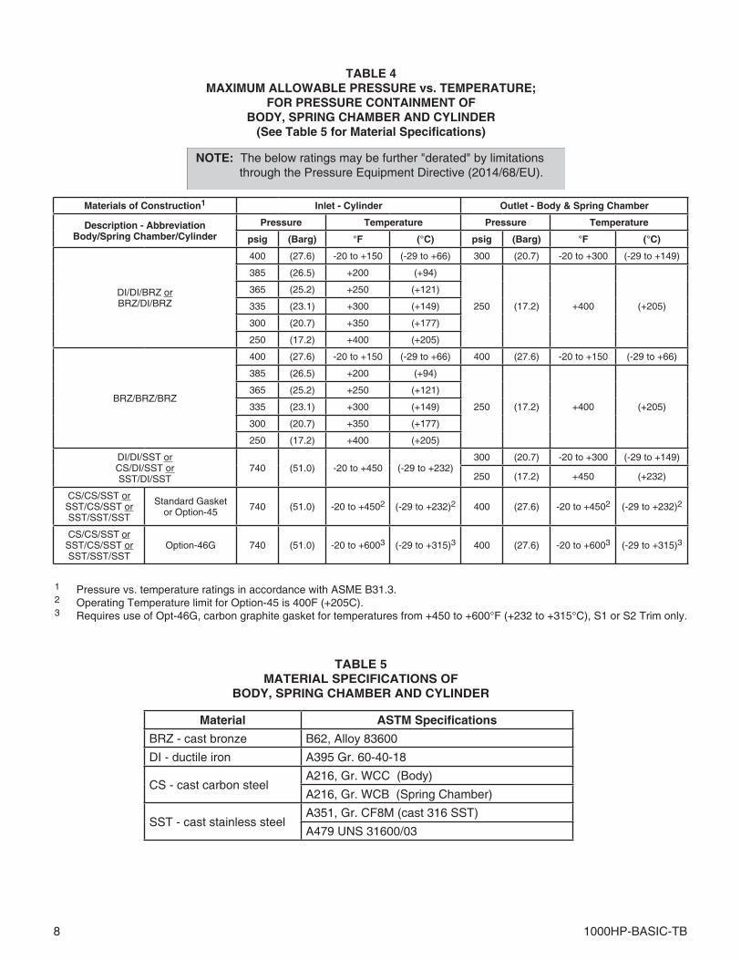
TABLE 4MAXIMUM ALLOWABLE PRESSURE vs. TEMPERATURE;
FOR PRESSURE CONTAINMENT OFBODY, SPRING CHAMBER AND CYLINDER
(See Table 5 for Material Specifications)
1 Pressure vs. temperature ratings in accordance with ASME B31.3.2 Operating Temperature limit for Option-45 is 400F (+205C).3 Requires use of Opt-46G, carbon graphite gasket for temperatures from +450 to +600°F (+232 to +315°C), S1 or S2 Trim only.
NOTE: The below ratings may be further "derated" by limitations through the Pressure Equipment Directive (2014/68/EU).
TABLE 5MATERIAL SPECIFICATIONS OF
BODY, SPRING CHAMBER AND CYLINDER
Materials of Construction1 Inlet - Cylinder Outlet - Body & Spring Chamber
Description - Abbreviation Body/Spring Chamber/Cylinder
Pressure Temperature Pressure Temperature
psig (Barg) °F (°C) psig (Barg) °F (°C)
DI/DI/BRZ orBRZ/DI/BRZ
400 (27.6) -20 to +150 (-29 to +66) 300 (20.7) -20 to +300 (-29 to +149)
385 (26.5) +200 (+94)
250 (17.2) +400 (+205)
365 (25.2) +250 (+121)
335 (23.1) +300 (+149)
300 (20.7) +350 (+177)
250 (17.2) +400 (+205)
BRZ/BRZ/BRZ
400 (27.6) -20 to +150 (-29 to +66) 400 (27.6) -20 to +150 (-29 to +66)
385 (26.5) +200 (+94)
250 (17.2) +400 (+205)
365 (25.2) +250 (+121)
335 (23.1) +300 (+149)
300 (20.7) +350 (+177)
250 (17.2) +400 (+205)
DI/DI/SST orCS/DI/SST orSST/DI/SST
740 (51.0) -20 to +450 (-29 to +232)300 (20.7) -20 to +300 (-29 to +149)
250 (17.2) +450 (+232)
CS/CS/SST orSST/CS/SST orSST/SST/SST
Standard Gasketor Option-45 740 (51.0) -20 to +4502 (-29 to +232)2 400 (27.6) -20 to +4502 (-29 to +232)2
CS/CS/SST orSST/CS/SST orSST/SST/SST
Option-46G 740 (51.0) -20 to +6003 (-29 to +315)3 400 (27.6) -20 to +6003 (-29 to +315)3
Material ASTM Specifications
BRZ - cast bronze B62, Alloy 83600
DI - ductile iron A395 Gr. 60-40-18
CS - cast carbon steelA216, Gr. WCC (Body)
A216, Gr. WCB (Spring Chamber)
SST - cast stainless steelA351, Gr. CF8M (cast 316 SST)
A479 UNS 31600/03
1000HP-BASIC-TB 9
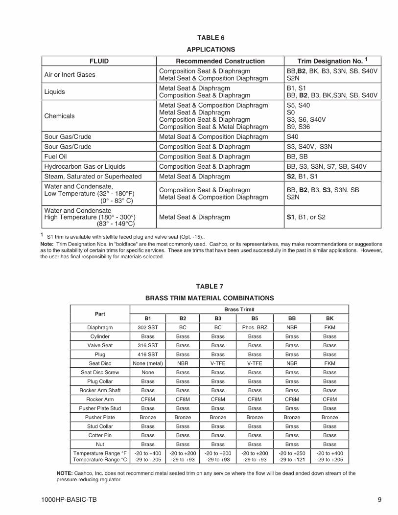
TABLE 6
APPLICATIONS
TABLE 7
BRASS TRIM MATERIAL COMBINATIONS
1 S1 trim is available with stellite faced plug and valve seat (Opt. -15)..Note: Trim Designation Nos. in "boldface" are the most commonly used. Cashco, or its representatives, may make recommendations or suggestions as to the suitability of certain trims for specific services. These are trims that have been used successfully in the past in similar applications. However, the user has final responsibility for materials selected.
NOTE: Cashco, Inc. does not recommend metal seated trim on any service where the flow will be dead ended down stream of the pressure reducing regulator.
PartBrass Trim#
B1 B2 B3 B5 BB BK
Diaphragm 302 SST BC BC Phos. BRZ NBR FKM
Cylinder Brass Brass Brass Brass Brass Brass
Valve Seat 316 SST Brass Brass Brass Brass Brass
Plug 416 SST Brass Brass Brass Brass Brass
Seat Disc None (metal) NBR V-TFE V-TFE NBR FKM
Seat Disc Screw None Brass Brass Brass Brass Brass
Plug Collar Brass Brass Brass Brass Brass Brass
Rocker Arm Shaft Brass Brass Brass Brass Brass Brass
Rocker Arm CF8M CF8M CF8M CF8M CF8M CF8M
Pusher Plate Stud Brass Brass Brass Brass Brass Brass
Pusher Plate Bronze Bronze Bronze Bronze Bronze Bronze
Stud Collar Brass Brass Brass Brass Brass Brass
Cotter Pin Brass Brass Brass Brass Brass Brass
Nut Brass Brass Brass Brass Brass Brass
Temperature Range °FTemperature Range °C
-20 to +400-29 to +205
-20 to +200-29 to +93
-20 to +200-29 to +93
-20 to +200-29 to +93
-20 to +250-29 to +121
-20 to +400-29 to +205
FLUID Recommended Construction Trim Designation No. 1
Air or Inert Gases Composition Seat & DiaphragmMetal Seat & Composition Diaphragm
BB,B2, BK, B3, S3N, SB, S40VS2N
Liquids Metal Seat & DiaphragmComposition Seat & Diaphragm
B1, S1BB, B2, B3, BK,S3N, SB, S40V
Chemicals
Metal Seat & Composition DiaphragmMetal Seat & DiaphragmComposition Seat & DiaphragmComposition Seat & Metal Diaphragm
S5, S40S0S3, S6, S40VS9, S36
Sour Gas/Crude Metal Seat & Composition Diaphragm S40
Sour Gas/Crude Composition Seat & Diaphragm S3, S40V, S3N
Fuel Oil Composition Seat & Diaphragm BB, SB
Hydrocarbon Gas or Liquids Composition Seat & Diaphragm BB, S3, S3N, S7, SB, S40V
Steam, Saturated or Superheated Metal Seat & Diaphragm S2, B1, S1
Water and Condensate,Low Temperature (32° - 180°F) (0° - 83° C)
Composition Seat & DiaphragmMetal Seat & Composition Diaphragm
BB, B2, B3, S3, S3N. SBS2N
Water and CondensateHigh Temperature (180° - 300°) (83° - 149°C)
Metal Seat & Diaphragm S1, B1, or S2
10 1000HP-BASIC-TB
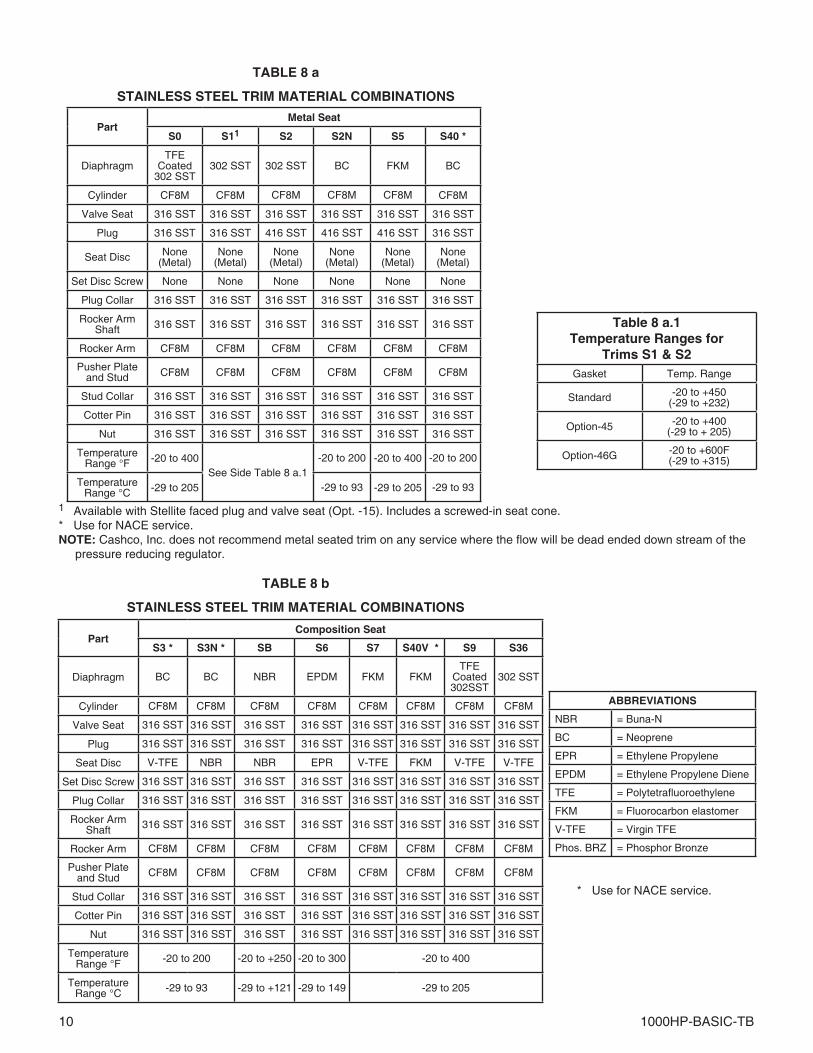
TABLE 8 a
STAINLESS STEEL TRIM MATERIAL COMBINATIONS
1 Available with Stellite faced plug and valve seat (Opt. -15). Includes a screwed-in seat cone.* Use for NACE service.NOTE: Cashco, Inc. does not recommend metal seated trim on any service where the flow will be dead ended down stream of the pressure reducing regulator.
PartMetal Seat
S0 S11 S2 S2N S5 S40 *
DiaphragmTFE
Coated302 SST
302 SST 302 SST BC FKM BC
Cylinder CF8M CF8M CF8M CF8M CF8M CF8M
Valve Seat 316 SST 316 SST 316 SST 316 SST 316 SST 316 SST
Plug 316 SST 316 SST 416 SST 416 SST 416 SST 316 SST
Seat Disc None(Metal)
None(Metal)
None(Metal)
None(Metal)
None(Metal)
None(Metal)
Set Disc Screw None None None None None None
Plug Collar 316 SST 316 SST 316 SST 316 SST 316 SST 316 SST
Rocker Arm Shaft 316 SST 316 SST 316 SST 316 SST 316 SST 316 SST
Rocker Arm CF8M CF8M CF8M CF8M CF8M CF8M
Pusher Plate and Stud CF8M CF8M CF8M CF8M CF8M CF8M
Stud Collar 316 SST 316 SST 316 SST 316 SST 316 SST 316 SST
Cotter Pin 316 SST 316 SST 316 SST 316 SST 316 SST 316 SST
Nut 316 SST 316 SST 316 SST 316 SST 316 SST 316 SST
Temperature Range °F -20 to 400
See Side Table 8 a.1-20 to 200 -20 to 400 -20 to 200
Temperature Range °C -29 to 205 -29 to 93 -29 to 205 -29 to 93
ABBREVIATIONS
NBR = Buna-N
BC = Neoprene
EPR = Ethylene Propylene
EPDM = Ethylene Propylene Diene
TFE = Polytetrafluoroethylene
FKM = Fluorocarbon elastomer
V-TFE = Virgin TFE
Phos. BRZ = Phosphor Bronze
PartComposition Seat
S3 * S3N * SB S6 S7 S40V * S9 S36
Diaphragm BC BC NBR EPDM FKM FKMTFE
Coated302SST
302 SST
Cylinder CF8M CF8M CF8M CF8M CF8M CF8M CF8M CF8M
Valve Seat 316 SST 316 SST 316 SST 316 SST 316 SST 316 SST 316 SST 316 SST
Plug 316 SST 316 SST 316 SST 316 SST 316 SST 316 SST 316 SST 316 SST
Seat Disc V-TFE NBR NBR EPR V-TFE FKM V-TFE V-TFE
Set Disc Screw 316 SST 316 SST 316 SST 316 SST 316 SST 316 SST 316 SST 316 SST
Plug Collar 316 SST 316 SST 316 SST 316 SST 316 SST 316 SST 316 SST 316 SST
Rocker Arm Shaft 316 SST 316 SST 316 SST 316 SST 316 SST 316 SST 316 SST 316 SST
Rocker Arm CF8M CF8M CF8M CF8M CF8M CF8M CF8M CF8M
Pusher Plate and Stud CF8M CF8M CF8M CF8M CF8M CF8M CF8M CF8M
Stud Collar 316 SST 316 SST 316 SST 316 SST 316 SST 316 SST 316 SST 316 SST
Cotter Pin 316 SST 316 SST 316 SST 316 SST 316 SST 316 SST 316 SST 316 SST
Nut 316 SST 316 SST 316 SST 316 SST 316 SST 316 SST 316 SST 316 SST
Temperature Range °F -20 to 200 -20 to +250 -20 to 300 -20 to 400
Temperature Range °C -29 to 93 -29 to +121 -29 to 149 -29 to 205
TABLE 8 b
STAINLESS STEEL TRIM MATERIAL COMBINATIONS
* Use for NACE service.
Table 8 a.1Temperature Ranges for
Trims S1 & S2Gasket Temp. Range
Standard -20 to +450(-29 to +232)
Option-45 -20 to +400(-29 to + 205)
Option-46G -20 to +600F(-29 to +315)
1000HP-BASIC-TB 11
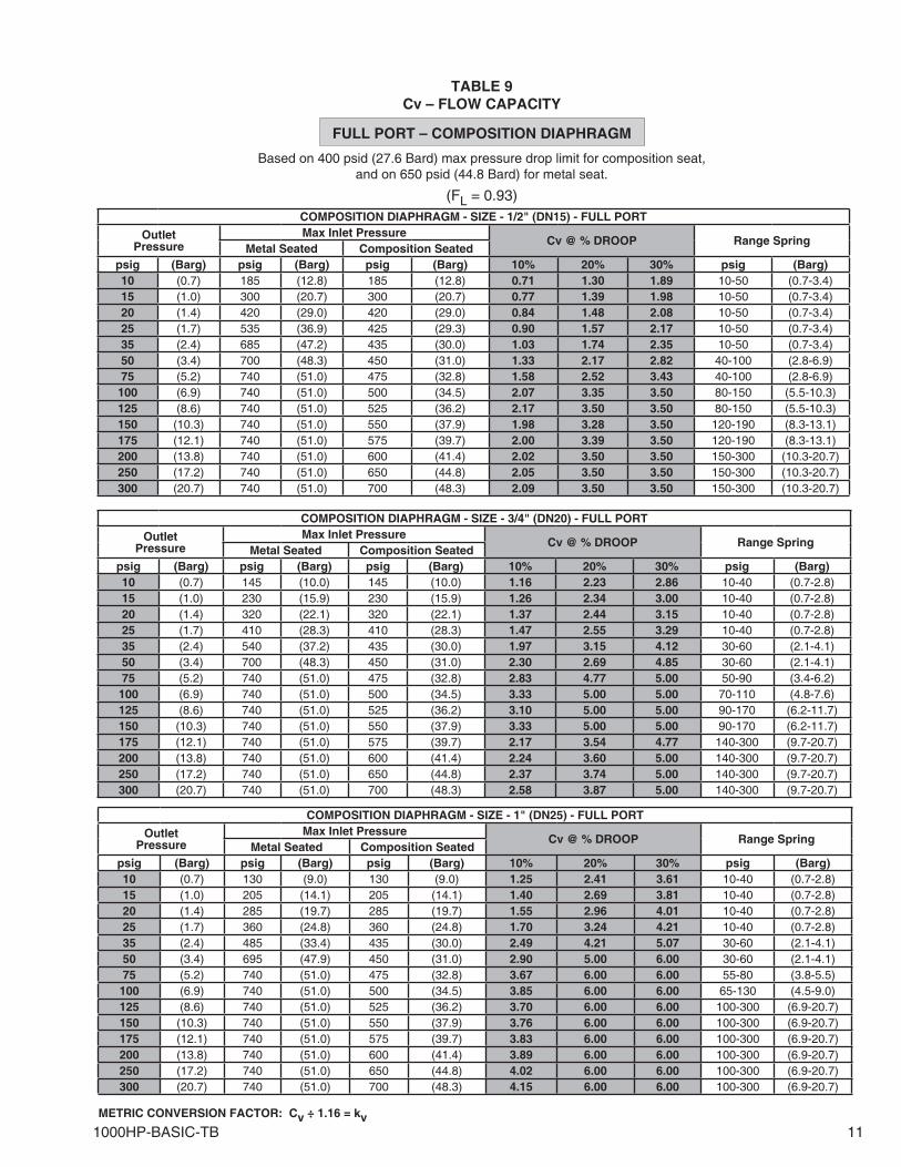
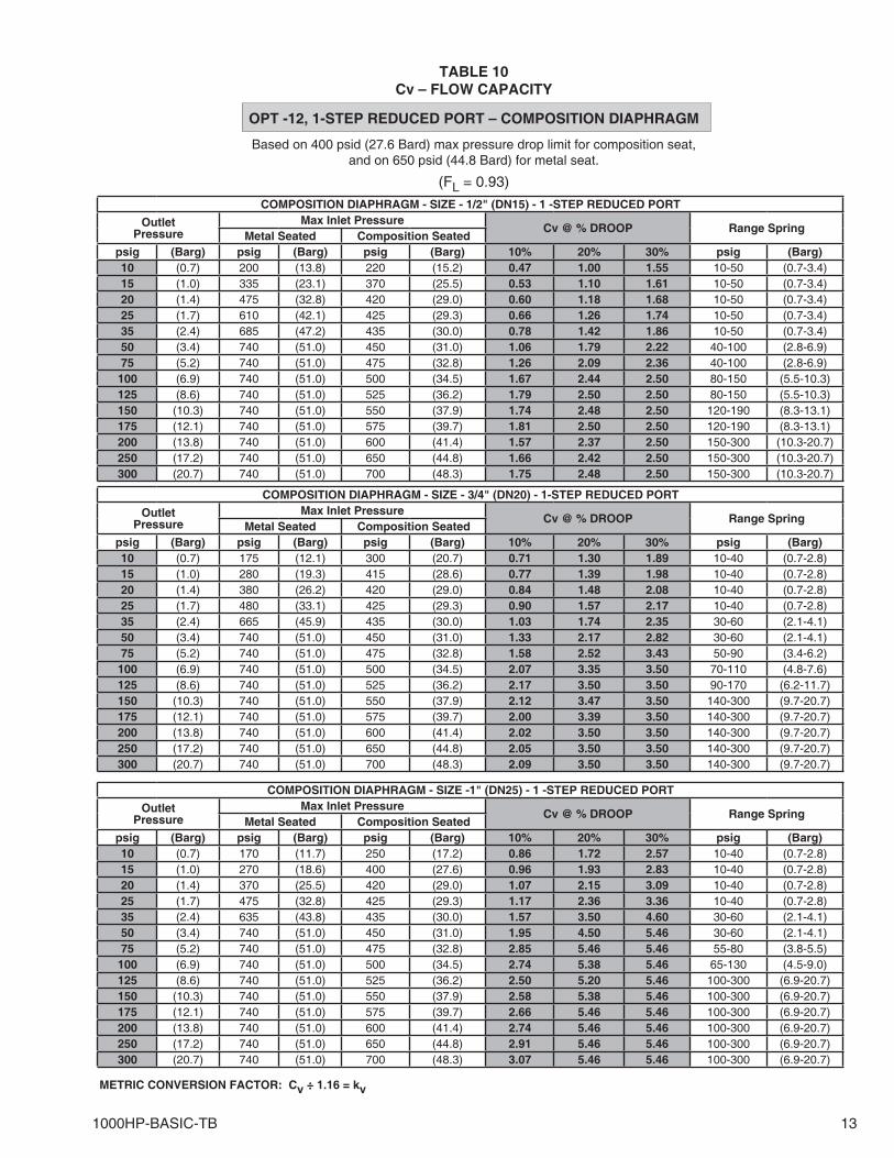
Based on 400 psid (27.6 Bard) max pressure drop limit for composition seat,and on 650 psid (44.8 Bard) for metal seat.
TABLE 9Cv – FLOW CAPACITY
FULL PORT – COMPOSITION DIAPHRAGM
(FL = 0.93)
METRIC CONVERSION FACTOR: Cv ÷ 1.16 = kv
COMPOSITION DIAPHRAGM - SIZE - 1/2" (DN15) - FULL PORT
OutletPressure
Max Inlet PressureCv @ % DROOP Range Spring
Metal Seated Composition Seatedpsig (Barg) psig (Barg) psig (Barg) 10% 20% 30% psig (Barg)10 (0.7) 185 (12.8) 185 (12.8) 0.71 1.30 1.89 10-50 (0.7-3.4)15 (1.0) 300 (20.7) 300 (20.7) 0.77 1.39 1.98 10-50 (0.7-3.4)20 (1.4) 420 (29.0) 420 (29.0) 0.84 1.48 2.08 10-50 (0.7-3.4)25 (1.7) 535 (36.9) 425 (29.3) 0.90 1.57 2.17 10-50 (0.7-3.4)35 (2.4) 685 (47.2) 435 (30.0) 1.03 1.74 2.35 10-50 (0.7-3.4)50 (3.4) 700 (48.3) 450 (31.0) 1.33 2.17 2.82 40-100 (2.8-6.9)75 (5.2) 740 (51.0) 475 (32.8) 1.58 2.52 3.43 40-100 (2.8-6.9)
100 (6.9) 740 (51.0) 500 (34.5) 2.07 3.35 3.50 80-150 (5.5-10.3)125 (8.6) 740 (51.0) 525 (36.2) 2.17 3.50 3.50 80-150 (5.5-10.3)150 (10.3) 740 (51.0) 550 (37.9) 1.98 3.28 3.50 120-190 (8.3-13.1)175 (12.1) 740 (51.0) 575 (39.7) 2.00 3.39 3.50 120-190 (8.3-13.1)200 (13.8) 740 (51.0) 600 (41.4) 2.02 3.50 3.50 150-300 (10.3-20.7)250 (17.2) 740 (51.0) 650 (44.8) 2.05 3.50 3.50 150-300 (10.3-20.7)300 (20.7) 740 (51.0) 700 (48.3) 2.09 3.50 3.50 150-300 (10.3-20.7)
COMPOSITION DIAPHRAGM - SIZE - 3/4" (DN20) - FULL PORT
OutletPressure
Max Inlet PressureCv @ % DROOP Range Spring
Metal Seated Composition Seatedpsig (Barg) psig (Barg) psig (Barg) 10% 20% 30% psig (Barg)10 (0.7) 145 (10.0) 145 (10.0) 1.16 2.23 2.86 10-40 (0.7-2.8)15 (1.0) 230 (15.9) 230 (15.9) 1.26 2.34 3.00 10-40 (0.7-2.8)20 (1.4) 320 (22.1) 320 (22.1) 1.37 2.44 3.15 10-40 (0.7-2.8)25 (1.7) 410 (28.3) 410 (28.3) 1.47 2.55 3.29 10-40 (0.7-2.8)35 (2.4) 540 (37.2) 435 (30.0) 1.97 3.15 4.12 30-60 (2.1-4.1)50 (3.4) 700 (48.3) 450 (31.0) 2.30 2.69 4.85 30-60 (2.1-4.1)75 (5.2) 740 (51.0) 475 (32.8) 2.83 4.77 5.00 50-90 (3.4-6.2)
100 (6.9) 740 (51.0) 500 (34.5) 3.33 5.00 5.00 70-110 (4.8-7.6)125 (8.6) 740 (51.0) 525 (36.2) 3.10 5.00 5.00 90-170 (6.2-11.7)150 (10.3) 740 (51.0) 550 (37.9) 3.33 5.00 5.00 90-170 (6.2-11.7)175 (12.1) 740 (51.0) 575 (39.7) 2.17 3.54 4.77 140-300 (9.7-20.7)200 (13.8) 740 (51.0) 600 (41.4) 2.24 3.60 5.00 140-300 (9.7-20.7)250 (17.2) 740 (51.0) 650 (44.8) 2.37 3.74 5.00 140-300 (9.7-20.7)300 (20.7) 740 (51.0) 700 (48.3) 2.58 3.87 5.00 140-300 (9.7-20.7)
COMPOSITION DIAPHRAGM - SIZE - 1" (DN25) - FULL PORT
OutletPressure
Max Inlet PressureCv @ % DROOP Range Spring
Metal Seated Composition Seatedpsig (Barg) psig (Barg) psig (Barg) 10% 20% 30% psig (Barg)10 (0.7) 130 (9.0) 130 (9.0) 1.25 2.41 3.61 10-40 (0.7-2.8)15 (1.0) 205 (14.1) 205 (14.1) 1.40 2.69 3.81 10-40 (0.7-2.8)20 (1.4) 285 (19.7) 285 (19.7) 1.55 2.96 4.01 10-40 (0.7-2.8)25 (1.7) 360 (24.8) 360 (24.8) 1.70 3.24 4.21 10-40 (0.7-2.8)35 (2.4) 485 (33.4) 435 (30.0) 2.49 4.21 5.07 30-60 (2.1-4.1)50 (3.4) 695 (47.9) 450 (31.0) 2.90 5.00 6.00 30-60 (2.1-4.1)75 (5.2) 740 (51.0) 475 (32.8) 3.67 6.00 6.00 55-80 (3.8-5.5)
100 (6.9) 740 (51.0) 500 (34.5) 3.85 6.00 6.00 65-130 (4.5-9.0)125 (8.6) 740 (51.0) 525 (36.2) 3.70 6.00 6.00 100-300 (6.9-20.7)150 (10.3) 740 (51.0) 550 (37.9) 3.76 6.00 6.00 100-300 (6.9-20.7)175 (12.1) 740 (51.0) 575 (39.7) 3.83 6.00 6.00 100-300 (6.9-20.7)200 (13.8) 740 (51.0) 600 (41.4) 3.89 6.00 6.00 100-300 (6.9-20.7)250 (17.2) 740 (51.0) 650 (44.8) 4.02 6.00 6.00 100-300 (6.9-20.7)300 (20.7) 740 (51.0) 700 (48.3) 4.15 6.00 6.00 100-300 (6.9-20.7)
12 1000HP-BASIC-TB
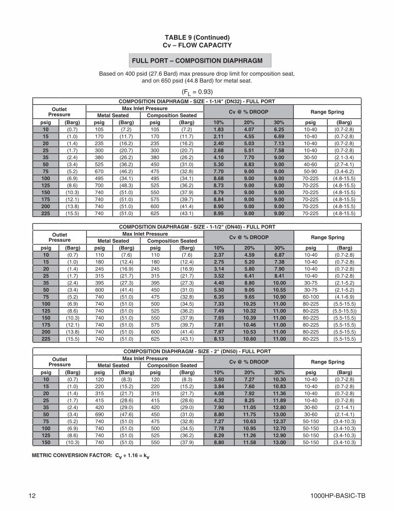
Based on 400 psid (27.6 Bard) max pressure drop limit for composition seat,and on 650 psid (44.8 Bard) for metal seat.
TABLE 9 (Continued)Cv – FLOW CAPACITY
FULL PORT – COMPOSITION DIAPHRAGM
(FL = 0.93)
METRIC CONVERSION FACTOR: Cv ÷ 1.16 = kv
COMPOSITION DIAPHRAGM - SIZE - 1-1/4" (DN32) - FULL PORT
OutletPressure
Max Inlet PressureCv @ % DROOP Range Spring
Metal Seated Composition Seatedpsig (Barg) psig (Barg) psig (Barg) 10% 20% 30% psig (Barg)10 (0.7) 105 (7.2) 105 (7.2) 1.83 4.07 6.25 10-40 (0.7-2.8)15 (1.0) 170 (11.7) 170 (11.7) 2.11 4.55 6.69 10-40 (0.7-2.8)20 (1.4) 235 (16.2) 235 (16.2) 2.40 5.03 7.13 10-40 (0.7-2.8)25 (1.7) 300 (20.7) 300 (20.7) 2.68 5.51 7.58 10-40 (0.7-2.8)35 (2.4) 380 (26.2) 380 (26.2) 4.10 7.70 9.00 30-50 (2.1-3.4)50 (3.4) 525 (36.2) 450 (31.0) 5.30 8.83 9.00 40-60 (2.7-4.1)75 (5.2) 670 (46.2) 475 (32.8) 7.70 9.00 9.00 50-90 (3.4-6.2)100 (6.9) 495 (34.1) 495 (34.1) 8.68 9.00 9.00 70-225 (4.8-15.5)125 (8.6) 700 (48.3) 525 (36.2) 8.73 9.00 9.00 70-225 (4.8-15.5)150 (10.3) 740 (51.0) 550 (37.9) 8.79 9.00 9.00 70-225 (4.8-15.5)175 (12.1) 740 (51.0) 575 (39.7) 8.84 9.00 9.00 70-225 (4.8-15.5)200 (13.8) 740 (51.0) 600 (41.4) 8.90 9.00 9.00 70-225 (4.8-15.5)225 (15.5) 740 (51.0) 625 (43.1) 8.95 9.00 9.00 70-225 (4.8-15.5)
COMPOSITION DIAPHRAGM - SIZE - 1-1/2" (DN40) - FULL PORT
OutletPressure
Max Inlet PressureCv @ % DROOP Range Spring
Metal Seated Composition Seatedpsig (Barg) psig (Barg) psig (Barg) 10% 20% 30% psig (Barg)10 (0.7) 110 (7.6) 110 (7.6) 2.37 4.59 6.87 10-40 (0.7-2.8)15 (1.0) 180 (12.4) 180 (12.4) 2.75 5.20 7.38 10-40 (0.7-2.8)20 (1.4) 245 (16.9) 245 (16.9) 3.14 5.80 7.90 10-40 (0.7-2.8)25 (1.7) 315 (21.7) 315 (21.7) 3.52 6.41 8.41 10-40 (0.7-2.8)35 (2.4) 395 (27.3) 395 (27.3) 4.40 8.80 10.00 30-75 (2.1-5.2)50 (3.4) 600 (41.4) 450 (31.0) 5.50 9.05 10.55 30-75 (2.1-5.2)75 (5.2) 740 (51.0) 475 (32.8) 6.35 9.65 10.90 60-100 (4.1-6.9)100 (6.9) 740 (51.0) 500 (34.5) 7.33 10.25 11.00 80-225 (5.5-15.5)125 (8.6) 740 (51.0) 525 (36.2) 7.49 10.32 11.00 80-225 (5.5-15.5))150 (10.3) 740 (51.0) 550 (37.9) 7.65 10.39 11.00 80-225 (5.5-15.5)175 (12.1) 740 (51.0) 575 (39.7) 7.81 10.46 11.00 80-225 (5.5-15.5)200 (13.8) 740 (51.0) 600 (41.4) 7.97 10.53 11.00 80-225 (5.5-15.5)225 (15.5) 740 (51.0) 625 (43.1) 8.13 10.60 11.00 80-225 (5.5-15.5)
COMPOSITION DIAPHRAGM - SIZE - 2" (DN50) - FULL PORT
OutletPressure
Max Inlet PressureCv @ % DROOP Range Spring
Metal Seated Composition Seatedpsig (Barg) psig (Barg) psig (Barg) 10% 20% 30% psig (Barg)10 (0.7) 120 (8.3) 120 (8.3) 3.60 7.27 10.30 10-40 (0.7-2.8)15 (1.0) 220 (15.2) 220 (15.2) 3.84 7.60 10.83 10-40 (0.7-2.8)20 (1.4) 315 (21.7) 315 (21.7) 4.08 7.92 11.36 10-40 (0.7-2.8)25 (1.7) 415 (28.6) 415 (28.6) 4.32 8.25 11.89 10-40 (0.7-2.8)35 (2.4) 420 (29.0) 420 (29.0) 7.90 11.05 12.80 30-60 (2.1-4.1)50 (3.4) 690 (47.6) 450 (31.0) 8.80 11.75 13.00 30-60 (2.1-4.1)75 (5.2) 740 (51.0) 475 (32.8) 7.27 10.63 12.37 50-150 (3.4-10.3)100 (6.9) 740 (51.0) 500 (34.5) 7.78 10.95 12.70 50-150 (3.4-10.3)125 (8.6) 740 (51.0) 525 (36.2) 8.29 11.26 12.90 50-150 (3.4-10.3)150 (10.3) 740 (51.0) 550 (37.9) 8.80 11.58 13.00 50-150 (3.4-10.3)
1000HP-BASIC-TB 13
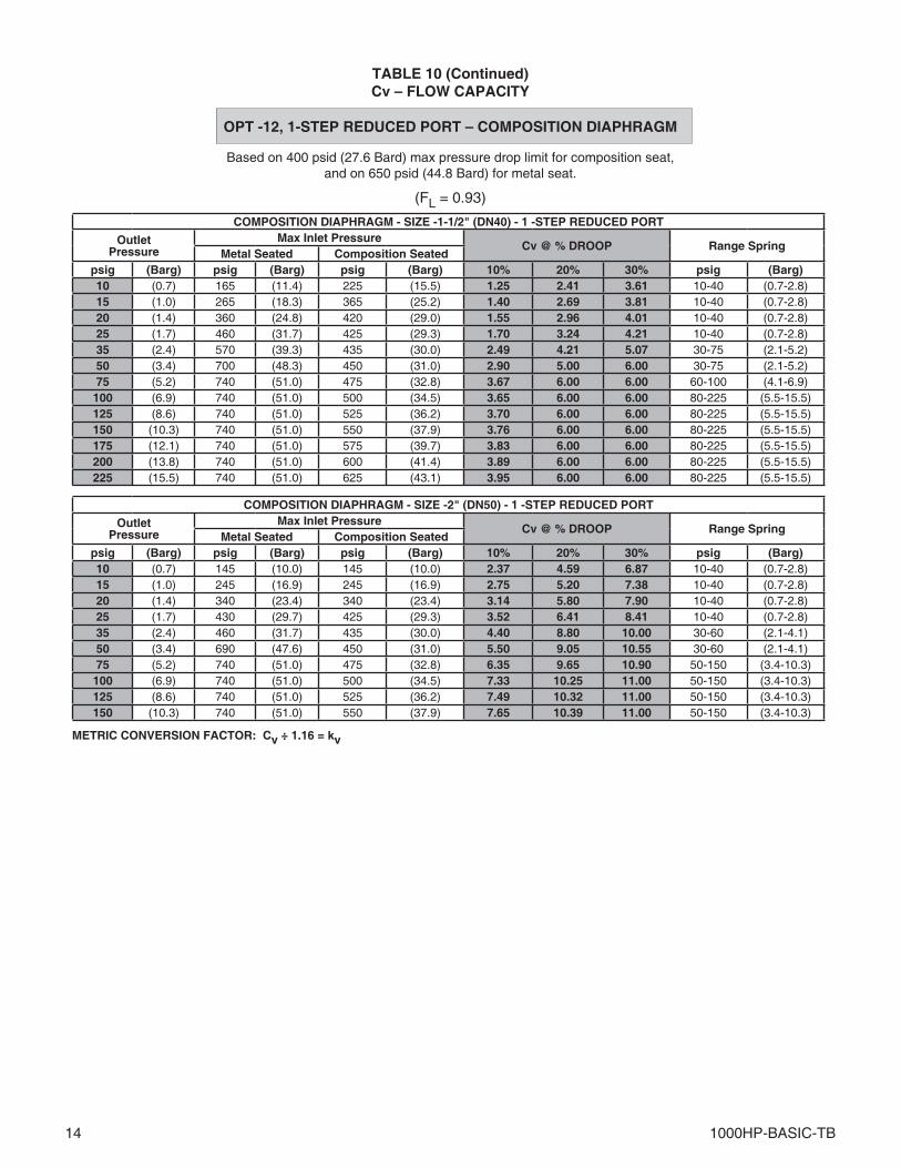
Based on 400 psid (27.6 Bard) max pressure drop limit for composition seat,and on 650 psid (44.8 Bard) for metal seat.
TABLE 10Cv – FLOW CAPACITY
OPT -12, 1-STEP REDUCED PORT – COMPOSITION DIAPHRAGM
(FL = 0.93)
METRIC CONVERSION FACTOR: Cv ÷ 1.16 = kv
COMPOSITION DIAPHRAGM - SIZE - 1/2" (DN15) - 1 -STEP REDUCED PORT
OutletPressure
Max Inlet PressureCv @ % DROOP Range Spring
Metal Seated Composition Seatedpsig (Barg) psig (Barg) psig (Barg) 10% 20% 30% psig (Barg)10 (0.7) 200 (13.8) 220 (15.2) 0.47 1.00 1.55 10-50 (0.7-3.4)15 (1.0) 335 (23.1) 370 (25.5) 0.53 1.10 1.61 10-50 (0.7-3.4)20 (1.4) 475 (32.8) 420 (29.0) 0.60 1.18 1.68 10-50 (0.7-3.4)25 (1.7) 610 (42.1) 425 (29.3) 0.66 1.26 1.74 10-50 (0.7-3.4)35 (2.4) 685 (47.2) 435 (30.0) 0.78 1.42 1.86 10-50 (0.7-3.4)50 (3.4) 740 (51.0) 450 (31.0) 1.06 1.79 2.22 40-100 (2.8-6.9)75 (5.2) 740 (51.0) 475 (32.8) 1.26 2.09 2.36 40-100 (2.8-6.9)
100 (6.9) 740 (51.0) 500 (34.5) 1.67 2.44 2.50 80-150 (5.5-10.3)125 (8.6) 740 (51.0) 525 (36.2) 1.79 2.50 2.50 80-150 (5.5-10.3)150 (10.3) 740 (51.0) 550 (37.9) 1.74 2.48 2.50 120-190 (8.3-13.1)175 (12.1) 740 (51.0) 575 (39.7) 1.81 2.50 2.50 120-190 (8.3-13.1)200 (13.8) 740 (51.0) 600 (41.4) 1.57 2.37 2.50 150-300 (10.3-20.7)250 (17.2) 740 (51.0) 650 (44.8) 1.66 2.42 2.50 150-300 (10.3-20.7)300 (20.7) 740 (51.0) 700 (48.3) 1.75 2.48 2.50 150-300 (10.3-20.7)
COMPOSITION DIAPHRAGM - SIZE - 3/4" (DN20) - 1-STEP REDUCED PORT
OutletPressure
Max Inlet PressureCv @ % DROOP Range Spring
Metal Seated Composition Seatedpsig (Barg) psig (Barg) psig (Barg) 10% 20% 30% psig (Barg)10 (0.7) 175 (12.1) 300 (20.7) 0.71 1.30 1.89 10-40 (0.7-2.8)15 (1.0) 280 (19.3) 415 (28.6) 0.77 1.39 1.98 10-40 (0.7-2.8)20 (1.4) 380 (26.2) 420 (29.0) 0.84 1.48 2.08 10-40 (0.7-2.8)25 (1.7) 480 (33.1) 425 (29.3) 0.90 1.57 2.17 10-40 (0.7-2.8)35 (2.4) 665 (45.9) 435 (30.0) 1.03 1.74 2.35 30-60 (2.1-4.1)50 (3.4) 740 (51.0) 450 (31.0) 1.33 2.17 2.82 30-60 (2.1-4.1)75 (5.2) 740 (51.0) 475 (32.8) 1.58 2.52 3.43 50-90 (3.4-6.2)
100 (6.9) 740 (51.0) 500 (34.5) 2.07 3.35 3.50 70-110 (4.8-7.6)125 (8.6) 740 (51.0) 525 (36.2) 2.17 3.50 3.50 90-170 (6.2-11.7)150 (10.3) 740 (51.0) 550 (37.9) 2.12 3.47 3.50 140-300 (9.7-20.7)175 (12.1) 740 (51.0) 575 (39.7) 2.00 3.39 3.50 140-300 (9.7-20.7)200 (13.8) 740 (51.0) 600 (41.4) 2.02 3.50 3.50 140-300 (9.7-20.7)250 (17.2) 740 (51.0) 650 (44.8) 2.05 3.50 3.50 140-300 (9.7-20.7)300 (20.7) 740 (51.0) 700 (48.3) 2.09 3.50 3.50 140-300 (9.7-20.7)
COMPOSITION DIAPHRAGM - SIZE -1" (DN25) - 1 -STEP REDUCED PORT
OutletPressure
Max Inlet PressureCv @ % DROOP Range Spring
Metal Seated Composition Seatedpsig (Barg) psig (Barg) psig (Barg) 10% 20% 30% psig (Barg)10 (0.7) 170 (11.7) 250 (17.2) 0.86 1.72 2.57 10-40 (0.7-2.8)15 (1.0) 270 (18.6) 400 (27.6) 0.96 1.93 2.83 10-40 (0.7-2.8)20 (1.4) 370 (25.5) 420 (29.0) 1.07 2.15 3.09 10-40 (0.7-2.8)25 (1.7) 475 (32.8) 425 (29.3) 1.17 2.36 3.36 10-40 (0.7-2.8)35 (2.4) 635 (43.8) 435 (30.0) 1.57 3.50 4.60 30-60 (2.1-4.1)50 (3.4) 740 (51.0) 450 (31.0) 1.95 4.50 5.46 30-60 (2.1-4.1)75 (5.2) 740 (51.0) 475 (32.8) 2.85 5.46 5.46 55-80 (3.8-5.5)
100 (6.9) 740 (51.0) 500 (34.5) 2.74 5.38 5.46 65-130 (4.5-9.0)125 (8.6) 740 (51.0) 525 (36.2) 2.50 5.20 5.46 100-300 (6.9-20.7)150 (10.3) 740 (51.0) 550 (37.9) 2.58 5.38 5.46 100-300 (6.9-20.7)175 (12.1) 740 (51.0) 575 (39.7) 2.66 5.46 5.46 100-300 (6.9-20.7)200 (13.8) 740 (51.0) 600 (41.4) 2.74 5.46 5.46 100-300 (6.9-20.7)250 (17.2) 740 (51.0) 650 (44.8) 2.91 5.46 5.46 100-300 (6.9-20.7)300 (20.7) 740 (51.0) 700 (48.3) 3.07 5.46 5.46 100-300 (6.9-20.7)
14 1000HP-BASIC-TB
Based on 400 psid (27.6 Bard) max pressure drop limit for composition seat,and on 650 psid (44.8 Bard) for metal seat.
TABLE 10 (Continued)Cv – FLOW CAPACITY
OPT -12, 1-STEP REDUCED PORT – COMPOSITION DIAPHRAGM
(FL = 0.93)
METRIC CONVERSION FACTOR: Cv ÷ 1.16 = kv
COMPOSITION DIAPHRAGM - SIZE -1-1/2" (DN40) - 1 -STEP REDUCED PORT
OutletPressure
Max Inlet PressureCv @ % DROOP Range Spring
Metal Seated Composition Seatedpsig (Barg) psig (Barg) psig (Barg) 10% 20% 30% psig (Barg)10 (0.7) 165 (11.4) 225 (15.5) 1.25 2.41 3.61 10-40 (0.7-2.8)15 (1.0) 265 (18.3) 365 (25.2) 1.40 2.69 3.81 10-40 (0.7-2.8)20 (1.4) 360 (24.8) 420 (29.0) 1.55 2.96 4.01 10-40 (0.7-2.8)25 (1.7) 460 (31.7) 425 (29.3) 1.70 3.24 4.21 10-40 (0.7-2.8)35 (2.4) 570 (39.3) 435 (30.0) 2.49 4.21 5.07 30-75 (2.1-5.2)50 (3.4) 700 (48.3) 450 (31.0) 2.90 5.00 6.00 30-75 (2.1-5.2)75 (5.2) 740 (51.0) 475 (32.8) 3.67 6.00 6.00 60-100 (4.1-6.9)100 (6.9) 740 (51.0) 500 (34.5) 3.65 6.00 6.00 80-225 (5.5-15.5)125 (8.6) 740 (51.0) 525 (36.2) 3.70 6.00 6.00 80-225 (5.5-15.5)150 (10.3) 740 (51.0) 550 (37.9) 3.76 6.00 6.00 80-225 (5.5-15.5)175 (12.1) 740 (51.0) 575 (39.7) 3.83 6.00 6.00 80-225 (5.5-15.5)200 (13.8) 740 (51.0) 600 (41.4) 3.89 6.00 6.00 80-225 (5.5-15.5)225 (15.5) 740 (51.0) 625 (43.1) 3.95 6.00 6.00 80-225 (5.5-15.5)
COMPOSITION DIAPHRAGM - SIZE -2" (DN50) - 1 -STEP REDUCED PORT
OutletPressure
Max Inlet PressureCv @ % DROOP Range Spring
Metal Seated Composition Seatedpsig (Barg) psig (Barg) psig (Barg) 10% 20% 30% psig (Barg)10 (0.7) 145 (10.0) 145 (10.0) 2.37 4.59 6.87 10-40 (0.7-2.8)15 (1.0) 245 (16.9) 245 (16.9) 2.75 5.20 7.38 10-40 (0.7-2.8)20 (1.4) 340 (23.4) 340 (23.4) 3.14 5.80 7.90 10-40 (0.7-2.8)25 (1.7) 430 (29.7) 425 (29.3) 3.52 6.41 8.41 10-40 (0.7-2.8)35 (2.4) 460 (31.7) 435 (30.0) 4.40 8.80 10.00 30-60 (2.1-4.1)50 (3.4) 690 (47.6) 450 (31.0) 5.50 9.05 10.55 30-60 (2.1-4.1)75 (5.2) 740 (51.0) 475 (32.8) 6.35 9.65 10.90 50-150 (3.4-10.3)100 (6.9) 740 (51.0) 500 (34.5) 7.33 10.25 11.00 50-150 (3.4-10.3)125 (8.6) 740 (51.0) 525 (36.2) 7.49 10.32 11.00 50-150 (3.4-10.3)150 (10.3) 740 (51.0) 550 (37.9) 7.65 10.39 11.00 50-150 (3.4-10.3)
1000HP-BASIC-TB 15
Based on 400 psid (27.6 Bard) max pressure drop limit for composition seat,and on 650 psid (44.8 Bard) for metal seat.
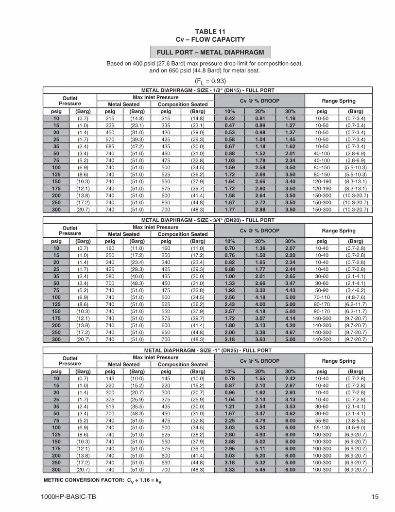
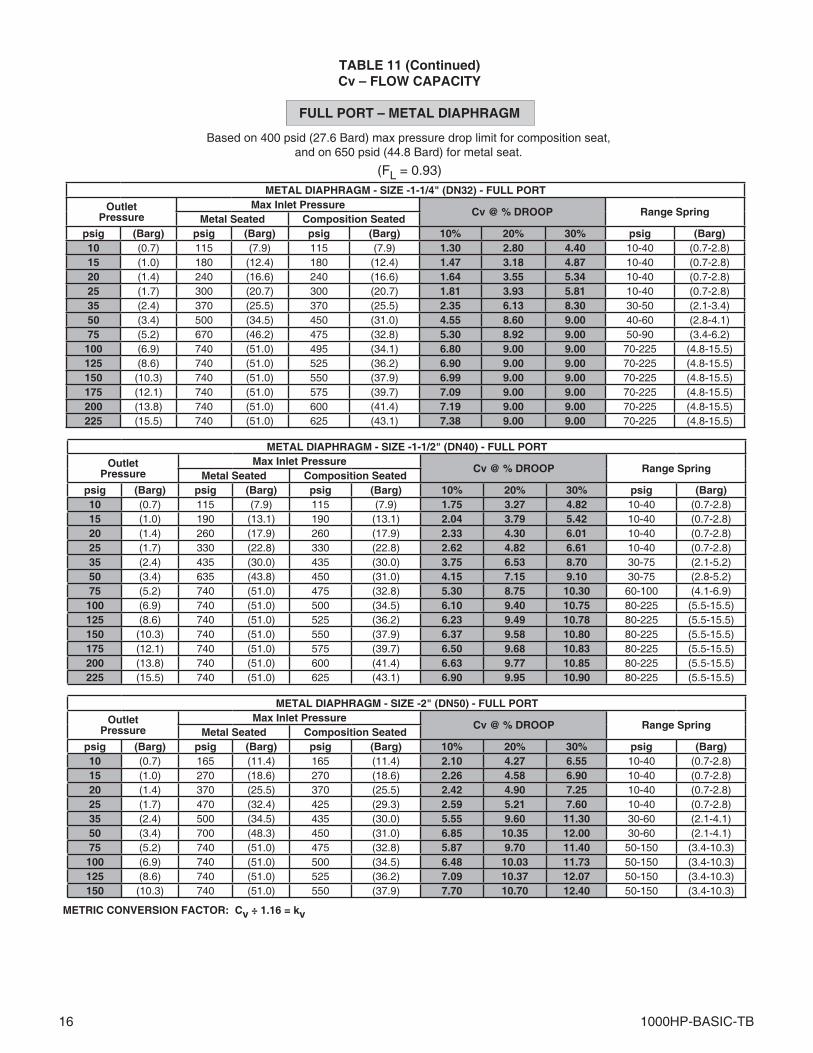
TABLE 11Cv – FLOW CAPACITY
FULL PORT – METAL DIAPHRAGM
(FL = 0.93)
METRIC CONVERSION FACTOR: Cv ÷ 1.16 = kv
METAL DIAPHRAGM - SIZE - 1/2" (DN15) - FULL PORT
OutletPressure
Max Inlet PressureCv @ % DROOP Range Spring
Metal Seated Composition Seatedpsig (Barg) psig (Barg) psig (Barg) 10% 20% 30% psig (Barg)10 (0.7) 215 (14.8) 215 (14.8) 0.42 0.81 1.18 10-50 (0.7-3.4)15 (1.0) 335 (23.1) 335 (23.1) 0.47 0.89 1.27 10-50 (0.7-3.4)20 (1.4) 450 (31.0) 420 (29.0) 0.53 0.98 1.37 10-50 (0.7-3.4)25 (1.7) 570 (39.3) 425 (29.3) 0.58 1.04 1.45 10-50 (0.7-3.4)35 (2.4) 685 (47.2) 435 (30.0) 0.67 1.18 1.62 10-50 (0.7-3.4)50 (3.4) 740 (51.0) 450 (31.0) 0.88 1.52 2.01 40-100 (2.8-6.9)75 (5.2) 740 (51.0) 475 (32.8) 1.03 1.78 2.34 40-100 (2.8-6.9)
100 (6.9) 740 (51.0) 500 (34.5) 1.59 2.58 3.50 80-150 (5.5-10.3)125 (8.6) 740 (51.0) 525 (36.2) 1.72 2.69 3.50 80-150 (5.5-10.3)150 (10.3) 740 (51.0) 550 (37.9) 1.64 2.66 3.40 120-190 (8.3-13.1)175 (12.1) 740 (51.0) 575 (39.7) 1.72 2.80 3.50 120-190 (8.3-13.1)200 (13.8) 740 (51.0) 600 (41.4) 1.58 2.64 3.50 150-300 (10.3-20.7)250 (17.2) 740 (51.0) 650 (44.8) 1.67 2.72 3.50 150-300 (10.3-20.7)300 (20.7) 740 (51.0) 700 (48.3) 1.77 2.88 3.50 150-300 (10.3-20.7)
METAL DIAPHRAGM - SIZE - 3/4" (DN20) - FULL PORT
OutletPressure
Max Inlet PressureCv @ % DROOP Range Spring
Metal Seated Composition Seatedpsig (Barg) psig (Barg) psig (Barg) 10% 20% 30% psig (Barg)10 (0.7) 160 (11.0) 160 (11.0) 0.70 1.36 2.07 10-40 (0.7-2.8)15 (1.0) 250 (17.2) 250 (17.2) 0.76 1.50 2.20 10-40 (0.7-2.8)20 (1.4) 340 (23.4) 340 (23.4) 0.82 1.65 2.34 10-40 (0.7-2.8)25 (1.7) 425 (29.3) 425 (29.3) 0.88 1.77 2.44 10-40 (0.7-2.8)35 (2.4) 580 (40.0) 435 (30.0) 1.00 2.01 2.65 30-60 (2.1-4.1)50 (3.4) 700 (48.3) 450 (31.0) 1.33 2.66 3.47 30-60 (2.1-4.1)75 (5.2) 740 (51.0) 475 (32.8) 1.93 3.32 4.43 50-90 (3.4-6.2)
100 (6.9) 740 (51.0) 500 (34.5) 2.56 4.18 5.00 70-110 (4.8-7.6)125 (8.6) 740 (51.0) 525 (36.2) 2.43 4.00 5.00 90-170 (6.2-11.7)150 (10.3) 740 (51.0) 550 (37.9) 2.57 4.18 5.00 90-170 (6.2-11.7)175 (12.1) 740 (51.0) 575 (39.7) 1.72 3.07 4.14 140-300 (9.7-20.7)200 (13.8) 740 (51.0) 600 (41.4) 1.80 3.13 4.20 140-300 (9.7-20.7)250 (17.2) 740 (51.0) 650 (44.8) 2.00 3.38 4.67 140-300 (9.7-20.7)300 (20.7) 740 (51.0) 700 (48.3) 2.18 3.63 5.00 140-300 (9.7-20.7)
METAL DIAPHRAGM - SIZE -1" (DN25) - FULL PORT
OutletPressure
Max Inlet PressureCv @ % DROOP Range Spring
Metal Seated Composition Seatedpsig (Barg) psig (Barg) psig (Barg) 10% 20% 30% psig (Barg)10 (0.7) 145 (10.0) 145 (10.0) 0.78 1.55 2.42 10-40 (0.7-2.8)15 (1.0) 220 (15.2) 220 (15.2) 0.87 2.10 2.67 10-40 (0.7-2.8)20 (1.4) 300 (20.7) 300 (20.7) 0.96 1.92 2.93 10-40 (0.7-2.8)25 (1.7) 375 (25.9) 375 (25.9) 1.04 2.13 3.13 10-40 (0.7-2.8)35 (2.4) 515 (35.5) 435 (30.0) 1.21 2.54 3.53 30-60 (2.1-4.1)50 (3.4) 700 (48.3) 450 (31.0) 1.67 3.47 4.62 30-60 (2.1-4.1)75 (5.2) 740 (51.0) 475 (32.8) 2.25 4.79 6.00 55-80 (3.8-5.5)
100 (6.9) 740 (51.0) 500 (34.5) 3.03 5.20 6.00 65-130 (4.5-9.0)125 (8.6) 740 (51.0) 525 (36.2) 2.80 4.93 6.00 100-300 (6.9-20.7)150 (10.3) 740 (51.0) 550 (37.9) 2.88 5.02 6.00 100-300 (6.9-20.7)175 (12.1) 740 (51.0) 575 (39.7) 2.95 5.11 6.00 100-300 (6.9-20.7)200 (13.8) 740 (51.0) 600 (41.4) 3.03 5.20 6.00 100-300 (6.9-20.7)250 (17.2) 740 (51.0) 650 (44.8) 3.18 5.32 6.00 100-300 (6.9-20.7)300 (20.7) 740 (51.0) 700 (48.3) 3.33 5.45 6.00 100-300 (6.9-20.7)
16 1000HP-BASIC-TB
Based on 400 psid (27.6 Bard) max pressure drop limit for composition seat,and on 650 psid (44.8 Bard) for metal seat.
TABLE 11 (Continued)Cv – FLOW CAPACITY
FULL PORT – METAL DIAPHRAGM
(FL = 0.93)
METRIC CONVERSION FACTOR: Cv ÷ 1.16 = kv
METAL DIAPHRAGM - SIZE -1-1/4" (DN32) - FULL PORT
OutletPressure
Max Inlet PressureCv @ % DROOP Range Spring
Metal Seated Composition Seatedpsig (Barg) psig (Barg) psig (Barg) 10% 20% 30% psig (Barg)10 (0.7) 115 (7.9) 115 (7.9) 1.30 2.80 4.40 10-40 (0.7-2.8)15 (1.0) 180 (12.4) 180 (12.4) 1.47 3.18 4.87 10-40 (0.7-2.8)20 (1.4) 240 (16.6) 240 (16.6) 1.64 3.55 5.34 10-40 (0.7-2.8)25 (1.7) 300 (20.7) 300 (20.7) 1.81 3.93 5.81 10-40 (0.7-2.8)35 (2.4) 370 (25.5) 370 (25.5) 2.35 6.13 8.30 30-50 (2.1-3.4)50 (3.4) 500 (34.5) 450 (31.0) 4.55 8.60 9.00 40-60 (2.8-4.1)75 (5.2) 670 (46.2) 475 (32.8) 5.30 8.92 9.00 50-90 (3.4-6.2)
100 (6.9) 740 (51.0) 495 (34.1) 6.80 9.00 9.00 70-225 (4.8-15.5)125 (8.6) 740 (51.0) 525 (36.2) 6.90 9.00 9.00 70-225 (4.8-15.5)150 (10.3) 740 (51.0) 550 (37.9) 6.99 9.00 9.00 70-225 (4.8-15.5)175 (12.1) 740 (51.0) 575 (39.7) 7.09 9.00 9.00 70-225 (4.8-15.5)200 (13.8) 740 (51.0) 600 (41.4) 7.19 9.00 9.00 70-225 (4.8-15.5)225 (15.5) 740 (51.0) 625 (43.1) 7.38 9.00 9.00 70-225 (4.8-15.5)
METAL DIAPHRAGM - SIZE -1-1/2" (DN40) - FULL PORT
OutletPressure
Max Inlet PressureCv @ % DROOP Range Spring
Metal Seated Composition Seatedpsig (Barg) psig (Barg) psig (Barg) 10% 20% 30% psig (Barg)10 (0.7) 115 (7.9) 115 (7.9) 1.75 3.27 4.82 10-40 (0.7-2.8)15 (1.0) 190 (13.1) 190 (13.1) 2.04 3.79 5.42 10-40 (0.7-2.8)20 (1.4) 260 (17.9) 260 (17.9) 2.33 4.30 6.01 10-40 (0.7-2.8)25 (1.7) 330 (22.8) 330 (22.8) 2.62 4.82 6.61 10-40 (0.7-2.8)35 (2.4) 435 (30.0) 435 (30.0) 3.75 6.53 8.70 30-75 (2.1-5.2)50 (3.4) 635 (43.8) 450 (31.0) 4.15 7.15 9.10 30-75 (2.8-5.2)75 (5.2) 740 (51.0) 475 (32.8) 5.30 8.75 10.30 60-100 (4.1-6.9)100 (6.9) 740 (51.0) 500 (34.5) 6.10 9.40 10.75 80-225 (5.5-15.5)125 (8.6) 740 (51.0) 525 (36.2) 6.23 9.49 10.78 80-225 (5.5-15.5)150 (10.3) 740 (51.0) 550 (37.9) 6.37 9.58 10.80 80-225 (5.5-15.5)175 (12.1) 740 (51.0) 575 (39.7) 6.50 9.68 10.83 80-225 (5.5-15.5)200 (13.8) 740 (51.0) 600 (41.4) 6.63 9.77 10.85 80-225 (5.5-15.5)225 (15.5) 740 (51.0) 625 (43.1) 6.90 9.95 10.90 80-225 (5.5-15.5)
METAL DIAPHRAGM - SIZE -2" (DN50) - FULL PORT
OutletPressure
Max Inlet PressureCv @ % DROOP Range Spring
Metal Seated Composition Seatedpsig (Barg) psig (Barg) psig (Barg) 10% 20% 30% psig (Barg)10 (0.7) 165 (11.4) 165 (11.4) 2.10 4.27 6.55 10-40 (0.7-2.8)15 (1.0) 270 (18.6) 270 (18.6) 2.26 4.58 6.90 10-40 (0.7-2.8)20 (1.4) 370 (25.5) 370 (25.5) 2.42 4.90 7.25 10-40 (0.7-2.8)25 (1.7) 470 (32.4) 425 (29.3) 2.59 5.21 7.60 10-40 (0.7-2.8)35 (2.4) 500 (34.5) 435 (30.0) 5.55 9.60 11.30 30-60 (2.1-4.1)50 (3.4) 700 (48.3) 450 (31.0) 6.85 10.35 12.00 30-60 (2.1-4.1)75 (5.2) 740 (51.0) 475 (32.8) 5.87 9.70 11.40 50-150 (3.4-10.3)100 (6.9) 740 (51.0) 500 (34.5) 6.48 10.03 11.73 50-150 (3.4-10.3)125 (8.6) 740 (51.0) 525 (36.2) 7.09 10.37 12.07 50-150 (3.4-10.3)150 (10.3) 740 (51.0) 550 (37.9) 7.70 10.70 12.40 50-150 (3.4-10.3)
1000HP-BASIC-TB 17
Based on 400 psid (27.6 Bard) max pressure drop limit for composition seat,and on 650 psid (44.8 Bard) for metal seat.
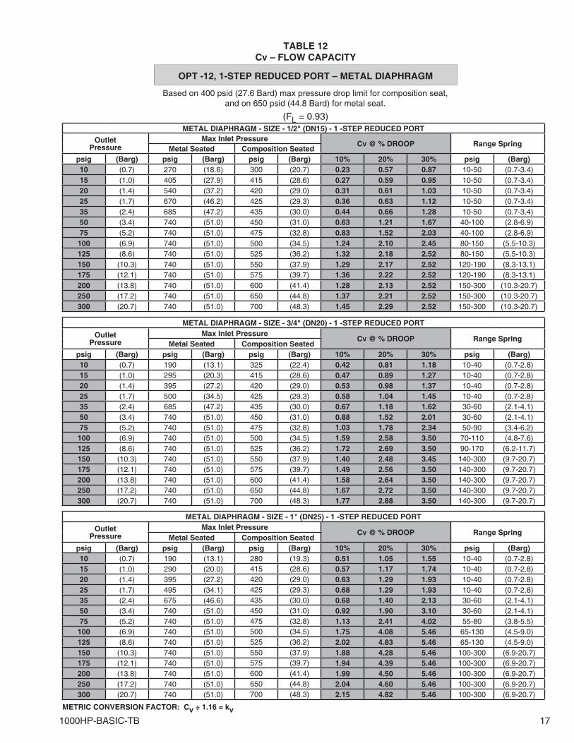
TABLE 12Cv – FLOW CAPACITY
OPT -12, 1-STEP REDUCED PORT – METAL DIAPHRAGM
(FL = 0.93)
METRIC CONVERSION FACTOR: Cv ÷ 1.16 = kv
METAL DIAPHRAGM - SIZE - 1/2" (DN15) - 1 -STEP REDUCED PORT
OutletPressure
Max Inlet PressureCv @ % DROOP Range Spring
Metal Seated Composition Seatedpsig (Barg) psig (Barg) psig (Barg) 10% 20% 30% psig (Barg)10 (0.7) 270 (18.6) 300 (20.7) 0.23 0.57 0.87 10-50 (0.7-3.4) 15 (1.0) 405 (27.9) 415 (28.6) 0.27 0.59 0.95 10-50 (0.7-3.4)20 (1.4) 540 (37.2) 420 (29.0) 0.31 0.61 1.03 10-50 (0.7-3.4)25 (1.7) 670 (46.2) 425 (29.3) 0.36 0.63 1.12 10-50 (0.7-3.4)35 (2.4) 685 (47.2) 435 (30.0) 0.44 0.66 1.28 10-50 (0.7-3.4)50 (3.4) 740 (51.0) 450 (31.0) 0.63 1.21 1.67 40-100 (2.8-6.9)75 (5.2) 740 (51.0) 475 (32.8) 0.83 1.52 2.03 40-100 (2.8-6.9)
100 (6.9) 740 (51.0) 500 (34.5) 1.24 2.10 2.45 80-150 (5.5-10.3)125 (8.6) 740 (51.0) 525 (36.2) 1.32 2.18 2.52 80-150 (5.5-10.3)150 (10.3) 740 (51.0) 550 (37.9) 1.29 2.17 2.52 120-190 (8.3-13.1)175 (12.1) 740 (51.0) 575 (39.7) 1.36 2.22 2.52 120-190 (8.3-13.1)200 (13.8) 740 (51.0) 600 (41.4) 1.28 2.13 2.52 150-300 (10.3-20.7)250 (17.2) 740 (51.0) 650 (44.8) 1.37 2.21 2.52 150-300 (10.3-20.7)300 (20.7) 740 (51.0) 700 (48.3) 1.45 2.29 2.52 150-300 (10.3-20.7)
METAL DIAPHRAGM - SIZE - 3/4" (DN20) - 1 -STEP REDUCED PORT
OutletPressure
Max Inlet PressureCv @ % DROOP Range Spring
Metal Seated Composition Seatedpsig (Barg) psig (Barg) psig (Barg) 10% 20% 30% psig (Barg)10 (0.7) 190 (13.1) 325 (22.4) 0.42 0.81 1.18 10-40 (0.7-2.8) 15 (1.0) 295 (20.3) 415 (28.6) 0.47 0.89 1.27 10-40 (0.7-2.8)20 (1.4) 395 (27.2) 420 (29.0) 0.53 0.98 1.37 10-40 (0.7-2.8)25 (1.7) 500 (34.5) 425 (29.3) 0.58 1.04 1.45 10-40 (0.7-2.8)35 (2.4) 685 (47.2) 435 (30.0) 0.67 1.18 1.62 30-60 (2.1-4.1)50 (3.4) 740 (51.0) 450 (31.0) 0.88 1.52 2.01 30-60 (2.1-4.1)75 (5.2) 740 (51.0) 475 (32.8) 1.03 1.78 2.34 50-90 (3.4-6.2)100 (6.9) 740 (51.0) 500 (34.5) 1.59 2.58 3.50 70-110 (4.8-7.6)125 (8.6) 740 (51.0) 525 (36.2) 1.72 2.69 3.50 90-170 (6.2-11.7)150 (10.3) 740 (51.0) 550 (37.9) 1.40 2.48 3.45 140-300 (9.7-20.7)175 (12.1) 740 (51.0) 575 (39.7) 1.49 2.56 3.50 140-300 (9.7-20.7)200 (13.8) 740 (51.0) 600 (41.4) 1.58 2.64 3.50 140-300 (9.7-20.7)250 (17.2) 740 (51.0) 650 (44.8) 1.67 2.72 3.50 140-300 (9.7-20.7)300 (20.7) 740 (51.0) 700 (48.3) 1.77 2.88 3.50 140-300 (9.7-20.7)
METAL DIAPHRAGM - SIZE - 1" (DN25) - 1 -STEP REDUCED PORT
OutletPressure
Max Inlet PressureCv @ % DROOP Range Spring
Metal Seated Composition Seatedpsig (Barg) psig (Barg) psig (Barg) 10% 20% 30% psig (Barg)10 (0.7) 190 (13.1) 280 (19.3) 0.51 1.05 1.55 10-40 (0.7-2.8) 15 (1.0) 290 (20.0) 415 (28.6) 0.57 1.17 1.74 10-40 (0.7-2.8)20 (1.4) 395 (27.2) 420 (29.0) 0.63 1.29 1.93 10-40 (0.7-2.8)25 (1.7) 495 (34.1) 425 (29.3) 0.68 1.29 1.93 10-40 (0.7-2.8)35 (2.4) 675 (46.6) 435 (30.0) 0.68 1.40 2.13 30-60 (2.1-4.1)50 (3.4) 740 (51.0) 450 (31.0) 0.92 1.90 3.10 30-60 (2.1-4.1)75 (5.2) 740 (51.0) 475 (32.8) 1.13 2.41 4.02 55-80 (3.8-5.5)100 (6.9) 740 (51.0) 500 (34.5) 1.75 4.08 5.46 65-130 (4.5-9.0)125 (8.6) 740 (51.0) 525 (36.2) 2.02 4.83 5.46 65-130 (4.5-9.0)150 (10.3) 740 (51.0) 550 (37.9) 1.88 4.28 5.46 100-300 (6.9-20.7)175 (12.1) 740 (51.0) 575 (39.7) 1.94 4.39 5.46 100-300 (6.9-20.7)200 (13.8) 740 (51.0) 600 (41.4) 1.99 4.50 5.46 100-300 (6.9-20.7)250 (17.2) 740 (51.0) 650 (44.8) 2.04 4.60 5.46 100-300 (6.9-20.7)300 (20.7) 740 (51.0) 700 (48.3) 2.15 4.82 5.46 100-300 (6.9-20.7)
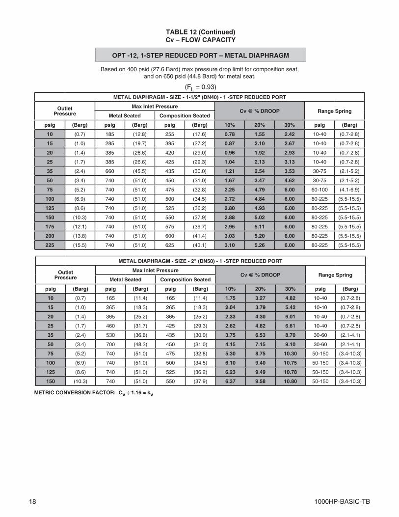
18 1000HP-BASIC-TB
Based on 400 psid (27.6 Bard) max pressure drop limit for composition seat,and on 650 psid (44.8 Bard) for metal seat.
TABLE 12 (Continued)Cv – FLOW CAPACITY
OPT -12, 1-STEP REDUCED PORT – METAL DIAPHRAGM
(FL = 0.93)
METRIC CONVERSION FACTOR: Cv ÷ 1.16 = kv
METAL DIAPHRAGM - SIZE - 1-1/2" (DN40) - 1 -STEP REDUCED PORT
OutletPressure
Max Inlet PressureCv @ % DROOP Range Spring
Metal Seated Composition Seated
psig (Barg) psig (Barg) psig (Barg) 10% 20% 30% psig (Barg)
10 (0.7) 185 (12.8) 255 (17.6) 0.78 1.55 2.42 10-40 (0.7-2.8)
15 (1.0) 285 (19.7) 395 (27.2) 0.87 2.10 2.67 10-40 (0.7-2.8)
20 (1.4) 385 (26.6) 420 (29.0) 0.96 1.92 2.93 10-40 (0.7-2.8)
25 (1.7) 385 (26.6) 425 (29.3) 1.04 2.13 3.13 10-40 (0.7-2.8)
35 (2.4) 660 (45.5) 435 (30.0) 1.21 2.54 3.53 30-75 (2.1-5.2)
50 (3.4) 740 (51.0) 450 (31.0) 1.67 3.47 4.62 30-75 (2.1-5.2)
75 (5.2) 740 (51.0) 475 (32.8) 2.25 4.79 6.00 60-100 (4.1-6.9)
100 (6.9) 740 (51.0) 500 (34.5) 2.72 4.84 6.00 80-225 (5.5-15.5)
125 (8.6) 740 (51.0) 525 (36.2) 2.80 4.93 6.00 80-225 (5.5-15.5)
150 (10.3) 740 (51.0) 550 (37.9) 2.88 5.02 6.00 80-225 (5.5-15.5)
175 (12.1) 740 (51.0) 575 (39.7) 2.95 5.11 6.00 80-225 (5.5-15.5)
200 (13.8) 740 (51.0) 600 (41.4) 3.03 5.20 6.00 80-225 (5.5-15.5)
225 (15.5) 740 (51.0) 625 (43.1) 3.10 5.26 6.00 80-225 (5.5-15.5)
METAL DIAPHRAGM - SIZE - 2" (DN50) - 1 -STEP REDUCED PORT
OutletPressure
Max Inlet PressureCv @ % DROOP Range Spring
Metal Seated Composition Seated
psig (Barg) psig (Barg) psig (Barg) 10% 20% 30% psig (Barg)
10 (0.7) 165 (11.4) 165 (11.4) 1.75 3.27 4.82 10-40 (0.7-2.8)
15 (1.0) 265 (18.3) 265 (18.3) 2.04 3.79 5.42 10-40 (0.7-2.8)
20 (1.4) 365 (25.2) 365 (25.2) 2.33 4.30 6.01 10-40 (0.7-2.8)
25 (1.7) 460 (31.7) 425 (29.3) 2.62 4.82 6.61 10-40 (0.7-2.8)
35 (2.4) 530 (36.6) 435 (30.0) 3.75 6.53 8.70 30-60 (2.1-4.1)
50 (3.4) 700 (48.3) 450 (31.0) 4.15 7.15 9.10 30-60 (2.1-4.1)
75 (5.2) 740 (51.0) 475 (32.8) 5.30 8.75 10.30 50-150 (3.4-10.3)
100 (6.9) 740 (51.0) 500 (34.5) 6.10 9.40 10.75 50-150 (3.4-10.3)
125 (8.6) 740 (51.0) 525 (36.2) 6.23 9.49 10.78 50-150 (3.4-10.3)
150 (10.3) 740 (51.0) 550 (37.9) 6.37 9.58 10.80 50-150 (3.4-10.3)
1000HP-BASIC-TB 19
NOTES: 1. Were “HI P1” is indicated, the inlet pressure exceeds the limit established in Table 9. 2. Where “HI P2” is indicated, the maximum outlet pressure is exceeded. 3. Where “CAV” is indicated, the flow has reached choked flow, full cavitation.
TABLE 13WATER CAPACITY - GPM
S.G. = 1.0 T = 60°F FL = 0.93
FULL PORT – COMPOSITION DIAPHRAGM & SEAT
Metric Conversion Factors: psi ÷ 14.5 = Bar; GPM X 3.785 = LPM
Outlet Pressure P2, psig
Inlet PressureP1, psig
PressureDroppsig
GPM @ 1/2" Body Size GPM @ 3/4" Body Size GPM @ 1" Body Size GPM @ 1-1/4" Body Size GPM @ 1-1/2" Body Size GPM @ 2" Body SizeDroop Droop Droop Droop Droop Droop
10% 20% 30% 10% 20% 30% 10% 20% 30% 10% 20% 30% 10% 20% 30% 10% 20% 30%
10
25 15 2.7 5.0 7.3 4.5 8.6 11.1 4.8 9.3 14.0 7.1 15.8 24.2 9.2 17.8 26.6 13.9 28.2 39.950 40 4.5 8.2 12.0 7.3 14.1 18.1 7.9 15.2 22.8 11.6 25.7 39.5 15.0 29.0 43.4 22.8 46.0 65.175 65 5.7 10.5 15.2 9.4 18.0 23.1 10.1 19.4 29.1 14.8 32.8 50.4 19.1 37.0 55.4 29.0 58.6 83.0
100 90 6.7 12.3 17.9 11.0 21.2 27.1 11.9 22.9 34.2 17.4 38.6 59.3 22.5 43.5 65.2 34.2 69.0 97.7125 115 7.6 13.9 20.3 12.4 23.9 30.7 13.4 25.8 38.7 HI P1 HI P1 HI P1 HI P1 HI P1 HI P1 HI P1 HI P1 HI P1150 140 8.4 15.4 22.4 HI P1 HI P1 HI P1 HI P1 HI P1 HI P1 HI P1 HI P1 HI P1 HI P1 HI P1 HI P1 HI P1 HI P1 HI P1175 165 9.1 16.7 24.3 HI P1 HI P1 HI P1 HI P1 HI P1 HI P1 HI P1 HI P1 HI P1 HI P1 HI P1 HI P1 HI P1 HI P1 HI P1 200 190 HI P1 HI P1 HI P1 HI P1 HI P1 HI P1 HI P1 HI P1 HI P1 HI P1 HI P1 HI P1 HI P1 HI P1 HI P1 HI P1 HI P1 HI P1
15
25 10 2.4 4.4 6.3 4.0 7.4 9.5 4.4 8.5 12.0 6.7 14.4 21.2 8.7 16.4 23.3 12.1 24.0 34.250 35 4.6 8.2 11.7 7.5 13.8 17.7 8.3 15.9 22.5 12.5 26.9 39.6 16.3 30.8 43.7 22.7 45.0 64.175 60 6.0 10.8 15.3 9.8 18.1 23.2 10.8 20.8 29.5 16.3 35.2 51.8 21.3 40.3 57.2 29.7 58.9 83.9
100 85 7.1 12.8 18.3 11.6 21.6 27.7 12.9 24.8 35.1 19.5 41.9 61.7 25.4 47.9 68.0 35.4 70.1 99.8125 110 8.1 14.6 20.8 13.2 24.5 31.5 14.7 28.2 40.0 22.1 47.7 70.2 28.8 54.5 77.4 40.3 79.7 113.6150 135 8.9 16.2 23.0 14.6 27.2 34.9 16.3 31.3 44.3 24.5 52.9 77.7 32.0 60.4 85.7 44.6 88.3 125.8175 160 9.7 17.6 25.0 15.9 29.6 37.9 17.7 34.0 48.2 HI P1 HI P1 HI P1 34.8 65.8 93.4 48.6 96.1 137.0200 185 10.5 18.9 26.9 17.1 31.8 40.8 19.0 36.6 51.8 HI P1 HI P1 HI P1 HI P1 HI P1 HI P1 52.2 103.4 147.3250 235 CAV CAV CAV HI P1 HI P1 HI P1 HI P1 HI P1 HI P1 HI P1 HI P1 HI P1 HI P1 HI P1 HI P1 HI P1 HI P1 HI P1
20
25 5 1.9 3.3 4.7 3.1 5.5 7.0 3.5 6.6 9.0 5.4 11.2 15.9 7.0 13.0 17.7 9.1 17.7 25.450 30 4.6 8.1 11.4 7.5 13.4 17.3 8.5 16.2 22.0 13.1 27.6 39.1 17.2 31.8 43.3 22.3 43.4 62.275 55 6.2 11.0 15.4 10.2 18.1 23.4 11.5 22.0 29.7 17.8 37.3 52.9 23.3 43.0 58.6 30.3 58.7 84.2
100 80 7.5 13.2 18.6 12.3 21.8 28.2 13.9 26.5 35.9 21.5 45.0 63.8 28.1 51.9 70.7 36.5 70.8 101.6125 105 8.6 15.2 21.3 14.0 25.0 32.3 15.9 30.3 41.1 24.6 51.5 73.1 32.2 59.4 81.0 41.8 81.2 116.4150 130 9.6 16.9 23.7 15.6 27.8 35.9 17.7 33.7 45.7 27.4 57.4 81.3 35.8 66.1 90.1 46.5 90.3 129.5175 155 10.5 18.4 25.9 17.1 30.4 39.2 19.3 36.9 49.9 29.9 62.6 88.8 39.1 72.2 98.4 50.8 98.6 141.4200 180 11.3 19.9 27.9 18.4 32.7 42.3 20.8 39.7 53.8 32.2 67.5 95.7 42.1 77.8 106.0 54.7 106.3 152.4250 230 12.7 22.4 31.5 20.8 37.0 47.8 23.5 44.9 60.8 HI P1 HI P1 HI P1 HI P1 HI P1 HI P1 61.9 120.1 172.3
25
50 25 4.5 7.9 10.9 7.4 12.8 16.5 8.5 16.2 21.1 13.4 27.6 37.9 17.6 32.1 42.1 21.6 41.3 59.575 50 6.4 11.1 15.3 10.4 18.0 23.3 12.0 22.9 29.8 19.0 39.0 53.6 24.9 45.3 59.5 30.5 58.3 84.1
100 75 7.8 13.6 18.8 12.7 22.1 28.5 14.7 28.1 36.5 23.2 47.7 65.6 30.5 55.5 72.8 37.4 71.4 103.0125 100 9.0 15.7 21.7 14.7 25.5 32.9 17.0 32.4 42.1 26.8 55.1 75.8 35.2 64.1 84.1 43.2 82.5 118.9150 125 10.1 17.6 24.3 16.4 28.5 36.8 19.0 36.2 47.1 30.0 61.6 84.7 39.4 71.7 94.0 48.3 92.2 132.9175 150 11.0 19.2 26.6 18.0 31.2 40.3 20.8 39.7 51.6 32.8 67.5 92.8 43.1 78.5 103.0 52.9 101.0 145.6200 175 11.9 20.8 28.7 19.4 33.7 43.5 22.5 42.9 55.7 35.5 72.9 100.3 46.6 84.8 111.3 57.1 109.1 157.3250 225 13.5 23.6 32.6 22.1 38.3 49.4 25.5 48.6 63.2 40.2 82.7 113.7 52.8 96.2 126.2 64.8 123.8 178.4
35
50 15 4.0 6.7 9.1 7.6 12.2 16.0 9.6 16.3 19.6 15.9 29.8 34.9 17.0 34.1 38.7 30.6 42.8 49.675 40 6.5 11.0 14.9 12.5 19.9 26.1 15.7 26.6 32.1 25.9 48.7 56.9 27.8 55.7 63.2 50.0 69.9 81.0
100 65 8.3 14.0 18.9 15.9 25.4 33.2 20.1 33.9 40.9 33.1 62.1 72.6 35.5 70.9 80.6 63.7 89.1 103.2125 90 9.8 16.5 22.3 18.7 29.9 39.1 23.6 39.9 48.1 38.9 73.0 85.4 41.7 83.5 94.9 74.9 104.8 121.4150 115 11.0 18.7 25.2 21.1 33.8 44.2 26.7 45.1 54.4 44.0 82.6 96.5 47.2 94.4 107.2 84.7 118.5 137.3175 140 12.2 20.6 27.8 23.3 37.3 48.7 29.5 49.8 60.0 48.5 91.1 106.5 52.1 104.1 118.3 93.5 130.7 151.5200 165 13.2 22.4 30.2 25.3 40.5 52.9 32.0 54.1 65.1 52.7 98.9 115.6 56.5 113.0 128.5 101.5 141.9 164.4250 215 15.1 25.5 34.5 28.9 46.2 60.4 36.5 61.7 74.3 60.1 112.9 132.0 64.5 129.0 146.6 115.8 162.0 187.7
50
75 25 6.7 10.9 14.1 11.5 13.5 24.3 14.5 25.0 30.0 26.5 44.2 45.0 27.5 45.3 52.8 44.0 58.8 65.0100 50 9.4 15.3 19.9 16.3 19.0 34.3 20.5 35.4 42.4 37.5 62.4 63.6 38.9 64.0 74.6 62.2 83.1 91.9125 75 11.5 18.8 24.4 19.9 23.3 42.0 25.1 43.3 52.0 45.9 76.5 77.9 47.6 78.4 91.4 76.2 101.8 112.6150 100 13.3 21.7 28.2 23.0 26.9 48.5 29.0 50.0 60.0 53.0 88.3 90.0 55.0 90.5 105.5 88.0 117.5 130.0175 125 14.9 24.3 31.5 25.7 30.1 54.2 32.4 55.9 67.1 59.3 98.7 100.6 61.5 101.2 118.0 98.4 131.4 145.3200 150 16.3 26.6 34.5 28.2 32.9 59.4 35.5 61.2 73.5 64.9 108.1 110.2 67.4 110.8 129.2 107.8 143.9 159.2250 200 18.8 30.7 39.9 32.5 38.0 68.6 41.0 70.7 84.9 75.0 124.9 127.3 77.8 128.0 149.2 124.5 166.2 183.8
75
100 25 7.9 12.6 17.2 14.2 23.9 25.0 18.4 30.0 30.0 38.5 45.0 45.0 31.8 48.3 54.5 36.4 53.2 61.9125 50 11.2 17.8 24.3 20.0 33.7 35.4 26.0 42.4 42.4 54.4 63.6 63.6 44.9 68.2 77.1 51.4 75.2 87.5150 75 13.7 21.8 29.7 24.5 41.3 43.3 31.8 52.0 52.0 66.7 77.9 77.9 55.0 83.6 94.4 63.0 92.1 107.1175 100 15.8 25.2 34.3 28.3 47.7 50.0 36.7 60.0 60.0 77.0 90.0 90.0 63.5 96.5 109.0 72.7 106.3 123.7200 125 17.7 28.2 38.3 31.6 53.3 55.9 41.0 67.1 67.1 86.1 100.6 100.6 71.0 107.9 121.9 81.3 118.8 138.3250 175 20.9 33.3 45.4 37.4 63.1 66.1 48.5 79.4 79.4 101.9 119.1 119.1 84.0 127.7 144.2 96.2 140.6 163.6
100
125 25 10.4 16.8 17.5 16.7 25.0 25.0 19.3 30.0 30.0 43.4 45.0 45.0 36.7 51.3 55.0 38.9 54.8 63.5150 50 14.6 23.7 24.7 23.5 35.4 35.4 27.2 42.4 42.4 61.4 63.6 63.6 51.8 72.5 77.8 55.0 77.4 89.8175 75 17.9 29.0 30.3 28.8 43.3 43.3 33.3 52.0 52.0 75.2 77.9 77.9 63.5 88.8 95.3 67.4 94.8 110.0200 100 20.7 33.5 35.0 33.3 50.0 50.0 38.5 60.0 60.0 86.8 90.0 90.0 73.3 102.5 110.0 77.8 109.5 127.0250 150 25.4 41.0 42.9 40.8 61.2 61.2 47.2 73.5 73.5 106.3 110.2 110.2 89.8 125.5 134.7 95.3 134.1 155.5
125
150 25 10.9 17.5 17.5 15.5 25.0 25.0 18.5 30.0 30.0 43.7 45.0 45.0 37.5 51.6 55.0 41.5 56.3 64.5175 50 15.3 24.7 24.7 21.9 35.4 35.4 26.2 42.4 42.4 61.7 63.6 63.6 53.0 73.0 77.8 58.6 79.6 91.2200 75 18.8 30.3 30.3 26.8 43.3 43.3 32.0 52.0 52.0 75.6 77.9 77.9 64.9 89.4 95.3 71.8 97.5 111.7250 125 24.3 39.1 39.1 34.7 55.9 55.9 41.4 67.1 67.1 97.6 100.6 100.6 83.7 115.4 123.0 92.7 125.9 144.2
150175 25 10.6 17.4 17.5 16.7 25.0 25.0 18.8 30.0 30.0 44.0 45.0 45.0 38.3 52.0 55.0 44.0 57.9 65.0200 50 15.0 24.5 24.7 23.5 35.4 35.4 26.6 42.4 42.4 62.2 63.6 63.6 54.1 73.5 77.8 62.2 81.9 91.9250 100 21.2 34.7 35.0 33.3 50.0 50.0 37.6 60.0 60.0 87.9 90.0 90.0 76.5 103.9 110.0 88.0 115.8 HI P1
175200 25 10.0 17.0 17.5 10.9 17.7 23.9 19.2 30.0 30.0 44.2 45.0 45.0 39.1 52.3 55.0 HI P1 HI P1 HI P1250 75 17.3 29.4 30.3 18.8 30.7 41.3 33.2 52.0 52.0 76.6 77.9 77.9 67.6 90.6 95.3 HI P1 HI P1 HI P1
200 250 50 14.3 24.7 24.7 15.8 25.5 35.4 27.5 42.4 42.4 62.9 63.6 63.6 56.4 74.5 77.8 HI P1 HI P1 HI P1
Size Max Velocity
Size Max Velocityin (mm) in. (mm)
1/2" (DN15) 15 fps 1-1/4" (DN32) 22.5 fps3/4" (DN20) 18 fps 1-1/2" (DN40) 25 fps1" (DN25) 20 fps 2" (DN50) 27 fps
20 1000HP-BASIC-TB
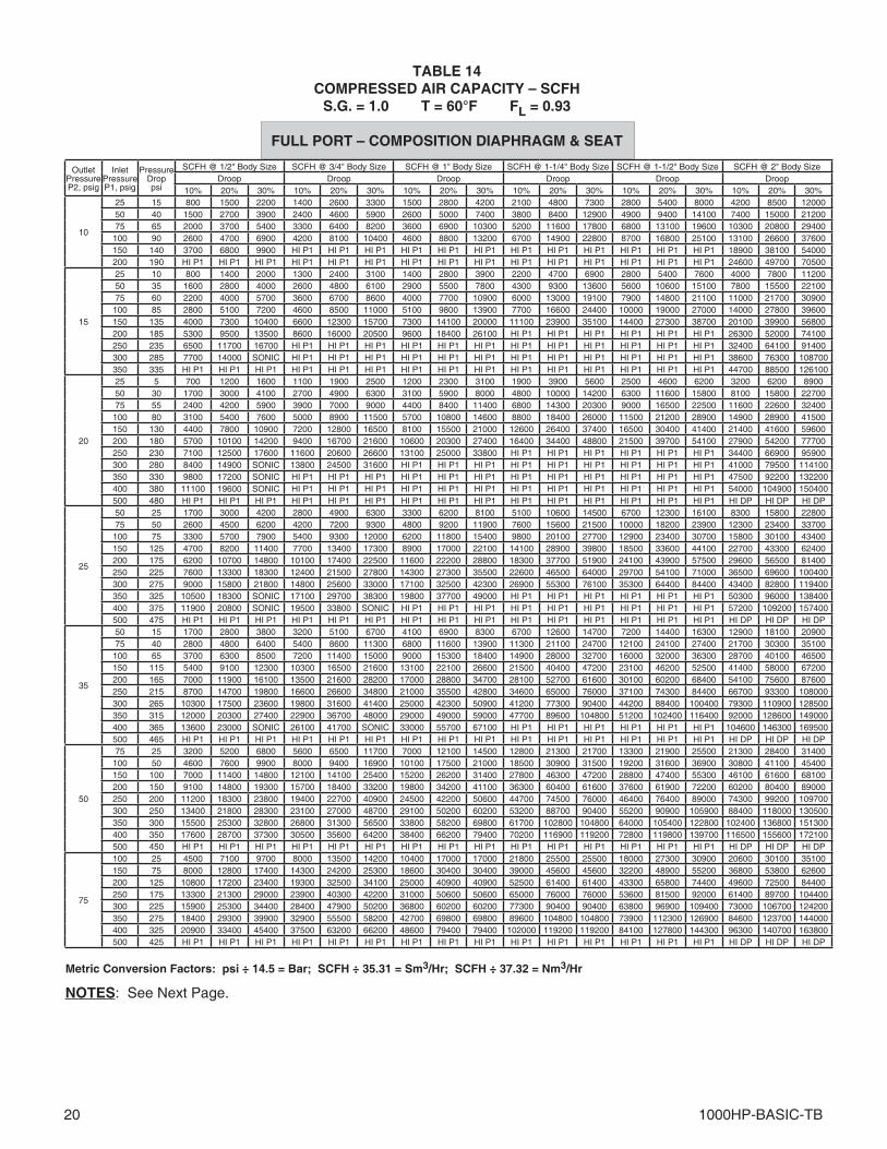
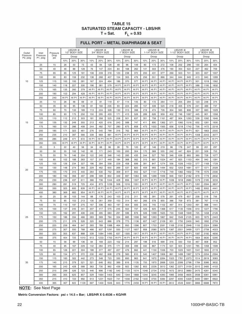
NOTES: See Next Page.
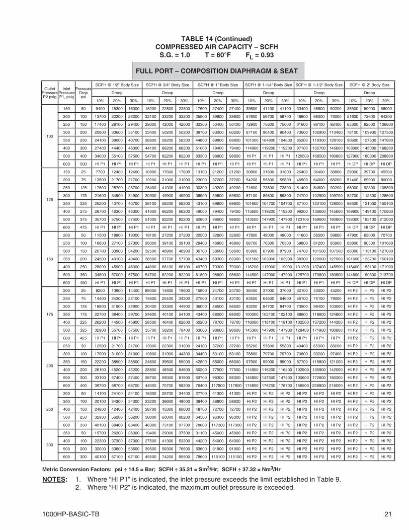
TABLE 14COMPRESSED AIR CAPACITY – SCFH
S.G. = 1.0 T = 60°F FL = 0.93
FULL PORT – COMPOSITION DIAPHRAGM & SEAT
Metric Conversion Factors: psi ÷ 14.5 = Bar; SCFH ÷ 35.31 = Sm3/Hr; SCFH ÷ 37.32 = Nm3/Hr
Outlet Pressure P2, psig
Inlet PressureP1, psig
PressureDroppsi
SCFH @ 1/2" Body Size SCFH @ 3/4" Body Size SCFH @ 1" Body Size SCFH @ 1-1/4" Body Size SCFH @ 1-1/2" Body Size SCFH @ 2" Body SizeDroop Droop Droop Droop Droop Droop
10% 20% 30% 10% 20% 30% 10% 20% 30% 10% 20% 30% 10% 20% 30% 10% 20% 30%
10
25 15 800 1500 2200 1400 2600 3300 1500 2800 4200 2100 4800 7300 2800 5400 8000 4200 8500 1200050 40 1500 2700 3900 2400 4600 5900 2600 5000 7400 3800 8400 12900 4900 9400 14100 7400 15000 2120075 65 2000 3700 5400 3300 6400 8200 3600 6900 10300 5200 11600 17800 6800 13100 19600 10300 20800 29400
100 90 2600 4700 6900 4200 8100 10400 4600 8800 13200 6700 14900 22800 8700 16800 25100 13100 26600 37600150 140 3700 6800 9900 HI P1 HI P1 HI P1 HI P1 HI P1 HI P1 HI P1 HI P1 HI P1 HI P1 HI P1 HI P1 18900 38100 54000200 190 HI P1 HI P1 HI P1 HI P1 HI P1 HI P1 HI P1 HI P1 HI P1 HI P1 HI P1 HI P1 HI P1 HI P1 HI P1 24600 49700 70500
15
25 10 800 1400 2000 1300 2400 3100 1400 2800 3900 2200 4700 6900 2800 5400 7600 4000 7800 1120050 35 1600 2800 4000 2600 4800 6100 2900 5500 7800 4300 9300 13600 5600 10600 15100 7800 15500 2210075 60 2200 4000 5700 3600 6700 8600 4000 7700 10900 6000 13000 19100 7900 14800 21100 11000 21700 30900
100 85 2800 5100 7200 4600 8500 11000 5100 9800 13900 7700 16600 24400 10000 19000 27000 14000 27800 39600150 135 4000 7300 10400 6600 12300 15700 7300 14100 20000 11100 23900 35100 14400 27300 38700 20100 39900 56800200 185 5300 9500 13500 8600 16000 20500 9600 18400 26100 HI P1 HI P1 HI P1 HI P1 HI P1 HI P1 26300 52000 74100250 235 6500 11700 16700 HI P1 HI P1 HI P1 HI P1 HI P1 HI P1 HI P1 HI P1 HI P1 HI P1 HI P1 HI P1 32400 64100 91400300 285 7700 14000 SONIC HI P1 HI P1 HI P1 HI P1 HI P1 HI P1 HI P1 HI P1 HI P1 HI P1 HI P1 HI P1 38600 76300 108700350 335 HI P1 HI P1 HI P1 HI P1 HI P1 HI P1 HI P1 HI P1 HI P1 HI P1 HI P1 HI P1 HI P1 HI P1 HI P1 44700 88500 126100
20
25 5 700 1200 1600 1100 1900 2500 1200 2300 3100 1900 3900 5600 2500 4600 6200 3200 6200 890050 30 1700 3000 4100 2700 4900 6300 3100 5900 8000 4800 10000 14200 6300 11600 15800 8100 15800 2270075 55 2400 4200 5900 3900 7000 9000 4400 8400 11400 6800 14300 20300 9000 16500 22500 11600 22600 32400
100 80 3100 5400 7600 5000 8900 11500 5700 10800 14600 8800 18400 26000 11500 21200 28900 14900 28900 41500150 130 4400 7800 10900 7200 12800 16500 8100 15500 21000 12600 26400 37400 16500 30400 41400 21400 41600 59600200 180 5700 10100 14200 9400 16700 21600 10600 20300 27400 16400 34400 48800 21500 39700 54100 27900 54200 77700250 230 7100 12500 17600 11600 20600 26600 13100 25000 33800 HI P1 HI P1 HI P1 HI P1 HI P1 HI P1 34400 66900 95900300 280 8400 14900 SONIC 13800 24500 31600 HI P1 HI P1 HI P1 HI P1 HI P1 HI P1 HI P1 HI P1 HI P1 41000 79500 114100350 330 9800 17200 SONIC HI P1 HI P1 HI P1 HI P1 HI P1 HI P1 HI P1 HI P1 HI P1 HI P1 HI P1 HI P1 47500 92200 132200400 380 11100 19600 SONIC HI P1 HI P1 HI P1 HI P1 HI P1 HI P1 HI P1 HI P1 HI P1 HI P1 HI P1 HI P1 54000 104900 150400500 480 HI P1 HI P1 HI P1 HI P1 HI P1 HI P1 HI P1 HI P1 HI P1 HI P1 HI P1 HI P1 HI P1 HI P1 HI P1 HI DP HI DP HI DP
25
50 25 1700 3000 4200 2800 4900 6300 3300 6200 8100 5100 10600 14500 6700 12300 16100 8300 15800 2280075 50 2600 4500 6200 4200 7200 9300 4800 9200 11900 7600 15600 21500 10000 18200 23900 12300 23400 33700
100 75 3300 5700 7900 5400 9300 12000 6200 11800 15400 9800 20100 27700 12900 23400 30700 15800 30100 43400150 125 4700 8200 11400 7700 13400 17300 8900 17000 22100 14100 28900 39800 18500 33600 44100 22700 43300 62400200 175 6200 10700 14800 10100 17400 22500 11600 22200 28800 18300 37700 51900 24100 43900 57500 29600 56500 81400250 225 7600 13300 18300 12400 21500 27800 14300 27300 35500 22600 46500 64000 29700 54100 71000 36500 69600 100400300 275 9000 15800 21800 14800 25600 33000 17100 32500 42300 26900 55300 76100 35300 64400 84400 43400 82800 119400350 325 10500 18300 SONIC 17100 29700 38300 19800 37700 49000 HI P1 HI P1 HI P1 HI P1 HI P1 HI P1 50300 96000 138400400 375 11900 20800 SONIC 19500 33800 SONIC HI P1 HI P1 HI P1 HI P1 HI P1 HI P1 HI P1 HI P1 HI P1 57200 109200 157400500 475 HI P1 HI P1 HI P1 HI P1 HI P1 HI P1 HI P1 HI P1 HI P1 HI P1 HI P1 HI P1 HI P1 HI P1 HI P1 HI DP HI DP HI DP
35
50 15 1700 2800 3800 3200 5100 6700 4100 6900 8300 6700 12600 14700 7200 14400 16300 12900 18100 2090075 40 2800 4800 6400 5400 8600 11300 6800 11600 13900 11300 21100 24700 12100 24100 27400 21700 30300 35100
100 65 3700 6300 8500 7200 11400 15000 9000 15300 18400 14900 28000 32700 16000 32000 36300 28700 40100 46500150 115 5400 9100 12300 10300 16500 21600 13100 22100 26600 21500 40400 47200 23100 46200 52500 41400 58000 67200200 165 7000 11900 16100 13500 21600 28200 17000 28800 34700 28100 52700 61600 30100 60200 68400 54100 75600 87600250 215 8700 14700 19800 16600 26600 34800 21000 35500 42800 34600 65000 76000 37100 74300 84400 66700 93300 108000300 265 10300 17500 23600 19800 31600 41400 25000 42300 50900 41200 77300 90400 44200 88400 100400 79300 110900 128500350 315 12000 20300 27400 22900 36700 48000 29000 49000 59000 47700 89600 104800 51200 102400 116400 92000 128600 149000400 365 13600 23000 SONIC 26100 41700 SONIC 33000 55700 67100 HI P1 HI P1 HI P1 HI P1 HI P1 HI P1 104600 146300 169500500 465 HI P1 HI P1 HI P1 HI P1 HI P1 HI P1 HI P1 HI P1 HI P1 HI P1 HI P1 HI P1 HI P1 HI P1 HI P1 HI DP HI DP HI DP
50
75 25 3200 5200 6800 5600 6500 11700 7000 12100 14500 12800 21300 21700 13300 21900 25500 21300 28400 31400100 50 4600 7600 9900 8000 9400 16900 10100 17500 21000 18500 30900 31500 19200 31600 36900 30800 41100 45400150 100 7000 11400 14800 12100 14100 25400 15200 26200 31400 27800 46300 47200 28800 47400 55300 46100 61600 68100200 150 9100 14800 19300 15700 18400 33200 19800 34200 41100 36300 60400 61600 37600 61900 72200 60200 80400 89000250 200 11200 18300 23800 19400 22700 40900 24500 42200 50600 44700 74500 76000 46400 76400 89000 74300 99200 109700300 250 13400 21800 28300 23100 27000 48700 29100 50200 60200 53200 88700 90400 55200 90900 105900 88400 118000 130500350 300 15500 25300 32800 26800 31300 56500 33800 58200 69800 61700 102800 104800 64000 105400 122800 102400 136800 151300400 350 17600 28700 37300 30500 35600 64200 38400 66200 79400 70200 116900 119200 72800 119800 139700 116500 155600 172100500 450 HI P1 HI P1 HI P1 HI P1 HI P1 HI P1 HI P1 HI P1 HI P1 HI P1 HI P1 HI P1 HI P1 HI P1 HI P1 HI DP HI DP HI DP
75
100 25 4500 7100 9700 8000 13500 14200 10400 17000 17000 21800 25500 25500 18000 27300 30900 20600 30100 35100150 75 8000 12800 17400 14300 24200 25300 18600 30400 30400 39000 45600 45600 32200 48900 55200 36800 53800 62600200 125 10800 17200 23400 19300 32500 34100 25000 40900 40900 52500 61400 61400 43300 65800 74400 49600 72500 84400250 175 13300 21300 29000 23900 40300 42200 31000 50600 50600 65000 76000 76000 53600 81500 92000 61400 89700 104400300 225 15900 25300 34400 28400 47900 50200 36800 60200 60200 77300 90400 90400 63800 96900 109400 73000 106700 124200350 275 18400 29300 39900 32900 55500 58200 42700 69800 69800 89600 104800 104800 73900 112300 126900 84600 123700 144000400 325 20900 33400 45400 37500 63200 66200 48600 79400 79400 102000 119200 119200 84100 127800 144300 96300 140700 163800500 425 HI P1 HI P1 HI P1 HI P1 HI P1 HI P1 HI P1 HI P1 HI P1 HI P1 HI P1 HI P1 HI P1 HI P1 HI P1 HI DP HI DP HI DP
1000HP-BASIC-TB 21
NOTES: 1. Where “HI P1” is in di cat ed, the inlet pres sure ex ceeds the limit es tab lished in Table 9. 2. Where “HI P2” is indicated, the max i mum outlet pressure is exceeded.
TABLE 14 (Continued)COMPRESSED AIR CAPACITY – SCFH
S.G. = 1.0 T = 60°F FL = 0.93
FULL PORT – COMPOSITION DIAPHRAGM & SEAT
Metric Conversion Factors: psi ÷ 14.5 = Bar; SCFH ÷ 35.31 = Sm3/Hr; SCFH ÷ 37.32 = Nm3/Hr
Outlet Pressure P2 psig
Inlet PressureP1, psig
PressureDroppsi
SCFH @ 1/2" Body Size SCFH @ 3/4" Body Size SCFH @ 1" Body Size SCFH @ 1-1/4" Body Size SCFH @ 1-1/2" Body Size SCFH @ 2" Body Size
Droop Droop Droop Droop Droop Droop
10% 20% 30% 10% 20% 30% 10% 20% 30% 10% 20% 30% 10% 20% 30% 10% 20% 30%
100
150 50 9400 15300 16000 15200 22800 22800 17600 27400 27400 39600 41100 41100 33400 46800 50200 35500 50000 58000
200 100 13700 22200 23200 22100 33200 33200 25500 39800 39800 57600 59700 59700 48600 68000 73000 51600 72600 84200
250 150 17400 28100 29400 28000 42000 42000 32300 50400 50400 72900 75600 75600 61600 86100 92400 65300 92000 106600
300 200 20800 33600 35100 33400 50200 50200 38700 60200 60200 87100 90400 90400 73600 102900 110400 78100 109900 127500
350 250 24100 39000 40700 38800 58200 58200 44800 69800 69800 101000 104800 104800 85300 119300 128100 90600 127500 147800
400 300 27400 44400 46300 44100 66200 66200 51000 79400 79400 114900 119200 119200 97100 135700 145600 103000 145000 168200
500 400 34000 55100 57500 54700 82200 82200 63300 98600 98600 HI P1 HI P1 HI P1 120500 168500 180800 127900 180000 208800
600 500 HI P1 HI P1 HI P1 HI P1 HI P1 HI P1 HI P1 HI P1 HI P1 HI P1 HI P1 HI P1 HI P1 HI P1 HI P1 HI DP HI DP HI DP
125
150 25 7700 12400 12400 10900 17600 17600 13100 21200 21200 30800 31800 31800 26400 36400 38800 29300 39700 45500
200 75 13500 21700 21700 19200 31000 31000 23000 37200 37200 54200 55800 55800 46500 64000 68200 51400 69900 80000
250 125 17800 28700 28700 25400 41000 41000 30300 49200 49200 71600 73800 73800 61400 84600 90200 68000 92300 105800
300 175 21600 34900 34900 30900 49900 49900 36900 59800 59800 87100 89800 89800 74700 102900 109700 82700 112300 128600
350 225 25200 40700 40700 36100 58200 58200 43100 69800 69800 101600 104700 104700 87100 120100 128000 96500 131000 150100
400 275 28700 46300 46300 41000 66200 66200 49000 79400 79400 115600 119200 119200 99200 136600 145600 109800 149100 170800
500 375 35700 57500 57500 51000 82200 82200 60800 98600 98600 143500 147900 147900 123100 169600 180800 136300 185100 212000
600 475 HI P1 HI P1 HI P1 HI P1 HI P1 HI P1 HI P1 HI P1 HI P1 HI P1 HI P1 HI P1 HI P1 HI P1 HI P1 HI DP HI DP HI DP
150
200 50 11500 18900 19000 18100 27200 27200 20500 32600 32600 47800 49000 49000 41600 56500 59800 47900 63000 70700
250 100 16600 27100 27300 26000 39100 39100 29400 46900 46900 68700 70300 70300 59800 81200 85900 68800 90500 101600
300 150 20700 33900 34200 32500 48900 48900 36700 58600 58600 85900 87900 87900 74700 101500 107500 86000 113100 127000
350 200 24500 40100 40400 38500 57700 57700 43400 69300 69300 101500 103900 103900 88300 120000 127000 101600 133700 150100
400 250 28000 45900 46300 44000 66100 66100 49700 79300 79300 116200 119000 119000 101200 137400 145500 116400 153100 171900
500 350 34800 57000 57500 54700 82200 82200 61800 98600 98600 144500 147900 147900 125700 170800 180800 144600 190300 213700
600 450 HI P1 HI P1 HI P1 HI P1 HI P1 HI P1 HI P1 HI P1 HI P1 HI P1 HI P1 HI P1 HI P1 HI P1 HI P1 HI DP HI DP HI DP
175
200 25 8200 13900 14400 89000 14600 19600 15800 24700 24700 36400 37000 37000 32100 43000 45200 HI P2 HI P2 HI P2
250 75 14400 24300 25100 15600 25400 34300 27500 43100 43100 63500 64600 64600 56100 75100 79000 HI P2 HI P2 HI P2
300 125 18800 31900 32900 20400 33300 44900 36000 56500 56500 83200 84700 84700 73500 98400 103500 HI P2 HI P2 HI P2
350 175 22700 38400 39700 24600 40100 54100 43400 68000 68000 100300 102100 102100 88600 118600 124800 HI P2 HI P2 HI P2
400 225 26200 44500 45900 28500 46400 62600 50200 78700 78700 116000 118100 118100 102500 137200 144300 HI P2 HI P2 HI P2
500 325 32900 55700 57500 35700 58200 78400 63000 98600 98600 145300 147900 147900 128400 171900 180800 HI P2 HI P2 HI P2
600 425 HI P1 HI P1 HI P1 HI P1 HI P1 HI P1 HI P1 HI P1 HI P1 HI P1 HI P1 HI P1 HI P1 HI P1 HI P1 HI P2 HI P2 HI P2
200
250 50 12500 21700 21700 13900 22300 31000 24100 37200 37200 55200 55800 55800 49400 65300 68200 HI P2 HI P2 HI P2
300 100 17900 31000 31000 19800 31900 44300 34400 53100 53100 78800 79700 79700 70600 93200 97400 HI P2 HI P2 HI P2
350 150 22200 38500 38500 24600 39600 55000 42800 66000 66000 97900 99000 99000 87700 115800 121000 HI P2 HI P2 HI P2
400 200 26100 45200 45200 28900 46500 64600 50200 77500 77500 114900 116200 116200 102900 135900 142000 HI P2 HI P2 HI P2
500 300 33100 57400 57400 36700 59000 81900 63700 98300 98300 145800 147500 147500 130600 172600 180300 HI P2 HI P2 HI P2
600 400 39700 68700 68700 44000 70700 98200 76400 117800 117800 174800 176700 176700 156500 206800 216000 HI P2 HI P2 HI P2
250
300 50 14100 24100 24100 16300 25700 34400 27700 41300 41300 HI P2 HI P2 HI P2 HI P2 HI P2 HI P2 HI P2 HI P2 HI P2
350 100 20100 34300 34300 23200 36600 49000 39400 58800 58800 HI P2 HI P2 HI P2 HI P2 HI P2 HI P2 HI P2 HI P2 HI P2
400 150 24800 42400 42400 28700 45300 60600 48700 72700 72700 HI P2 HI P2 HI P2 HI P2 HI P2 HI P2 HI P2 HI P2 HI P2
500 250 32900 56200 56200 38000 60000 80200 64500 96300 96300 HI P2 HI P2 HI P2 HI P2 HI P2 HI P2 HI P2 HI P2 HI P2
600 350 40100 68400 68400 46300 73100 97700 78600 117300 117300 HI P2 HI P2 HI P2 HI P2 HI P2 HI P2 HI P2 HI P2 HI P2
300
350 50 15700 26300 26300 19400 29000 37500 31100 45000 45000 HI P2 HI P2 HI P2 HI P2 HI P2 HI P2 HI P2 HI P2 HI P2
400 100 22300 37300 37300 27500 41300 53300 44200 64000 64000 HI P2 HI P2 HI P2 HI P2 HI P2 HI P2 HI P2 HI P2 HI P2
500 200 32000 53600 53600 39500 59300 76600 63600 91900 91900 HI P2 HI P2 HI P2 HI P2 HI P2 HI P2 HI P2 HI P2 HI P2
600 300 40100 67100 67100 49500 74200 95900 79600 115100 115100 HI P2 HI P2 HI P2 HI P2 HI P2 HI P2 HI P2 HI P2 HI P2
22 1000HP-BASIC-TB
NOTE: See Next Page
TABLE 15SATURATED STEAM CAPACITY - LBS/HR
T = Sat. FL = 0.93
FULL PORT – METAL DIAPHRAGM & SEAT
Metric Conversion Factors: psi ÷ 14.5 = Bar; LBS/HR X 0.4536 = KG/HR
Outlet Pressure P2, psig
Inlet PressureP1, psig
PressureDroppsi
LBS/HR @ 1/2" BODY SIZE
LBS/HR @3/4" BODY SIZE
LBS/HR @1" BODY SIZE
LBS/HR @1-1/4" BODY SIZE
LBS/HR @1-1/2" BODY SIZE
LBS/HR @2" BODY SIZE
Droop Droop Droop Droop Droop Droop
10% 20% 30% 10% 20% 30% 10% 20% 30% 10% 20% 30% 10% 20% 30% 10% 20% 30%
10
25 15 26 50 73 43 84 128 48 96 149 80 173 272 108 202 298 130 264 404
50 40 46 88 128 76 147 224 84 168 262 141 303 476 190 354 522 227 462 709
75 65 65 125 181 108 209 318 120 238 372 200 431 677 269 503 741 323 657 1007
100 90 83 159 232 138 268 407 154 305 476 256 551 866 344 644 949 413 840 1289
125 115 100 193 281 167 324 494 186 370 577 HI P1 HI P1 HI P1 HI P1 HI P1 HI P1 501 1018 1562
150 140 118 227 330 196 381 579 HI P1 HI P1 HI P1 HI P1 HI P1 HI P1 HI P1 HI P1 HI P1 588 1195 1832
175 165 135 260 379 HI P1 HI P1 HI P1 HI P1 HI P1 HI P1 HI P1 HI P1 HI P1 HI P1 HI P1 HI P1 HI P1 HI P1 HI P1
200 190 153 294 428 HI P1 HI P1 HI P1 HI P1 HI P1 HI P1 HI P1 HI P1 HI P1 HI P1 HI P1 HI P1 HI P1 HI P1 HI P1
250 240 HI P1 HI P1 HI P1 HI P1 HI P1 HI P1 HI P1 HI P1 HI P1 HI P1 HI P1 HI P1 HI P1 HI P1 HI P1 HI P1 HI P1 HI P1
15
25 10 26 48 69 41 81 119 47 114 145 80 172 264 111 205 294 123 248 374
50 35 50 95 136 81 160 235 93 224 285 157 339 520 218 405 579 241 489 737
75 60 70 133 189 113 224 328 130 313 398 219 474 726 304 565 808 337 683 1029
100 85 93 175 250 150 295 433 171 413 526 289 626 959 402 746 1067 445 901 1358
125 110 112 212 303 181 358 525 208 501 637 351 758 1161 487 904 1293 539 1092 1646
150 135 132 249 355 213 420 616 243 588 747 411 890 1362 571 1060 1516 632 1281 1930
175 160 151 286 408 244 482 707 280 675 858 473 1022 1565 656 1218 1742 726 1472 2218
200 185 171 323 461 276 545 799 316 762 969 HI P1 HI P1 HI P1 HI P1 HI P1 HI P1 821 1663 2505
250 235 210 397 566 339 669 981 HI P1 HI P1 HI P1 HI P1 HI P1 HI P1 HI P1 HI P1 HI P1 1008 2043 3077
300 285 249 471 672 HI P1 HI P1 HI P1 HI P1 HI P1 HI P1 HI P1 HI P1 HI P1 HI P1 HI P1 HI P1 HI P1 HI P1 HI P1
350 335 HI P1 HI P1 HI P1 HI P1 HI P1 HI P1 HI P1 HI P1 HI P1 HI P1 HI P1 HI P1 HI P1 HI P1 HI P1 HI P1 HI P1 HI P1
20
25 5 22 40 56 34 68 96 39 79 120 67 146 219 96 176 247 99 201 297
50 30 55 102 142 85 171 243 100 200 304 170 369 555 242 447 624 251 509 753
75 55 79 146 204 122 245 348 143 285 435 244 527 793 346 639 893 360 728 1077
100 80 102 188 263 157 317 449 184 368 562 315 681 1024 447 825 1153 464 940 1391
125 105 126 234 327 196 394 558 229 458 699 391 847 1274 556 1026 1433 577 1169 1729
150 130 148 274 383 229 462 655 269 537 820 459 993 1494 652 1203 1681 677 1371 2028
175 155 170 315 440 264 530 752 309 617 942 527 1141 1716 749 1382 1932 778 1575 2330
200 180 192 356 497 298 599 850 349 697 1064 595 1289 1939 846 1561 2182 879 1779 2632
250 230 236 437 611 366 736 1044 428 856 1307 HI P1 HI P1 HI P1 1039 1918 2680 1079 2185 3233
300 280 281 519 725 434 873 1239 508 1016 1551 HI P1 HI P1 HI P1 HI P1 HI P1 HI P1 1281 2594 3837
350 330 325 600 839 HI P1 HI P1 HI P1 HI P1 HI P1 HI P1 HI P1 HI P1 HI P1 HI P1 HI P1 HI P1 1482 3002 4441
400 380 369 683 954 HI P1 HI P1 HI P1 HI P1 HI P1 HI P1 HI P1 HI P1 HI P1 HI P1 HI P1 HI P1 HI P1 HI P1 HI P1
25
50 25 58 103 144 88 176 243 103 212 311 180 391 578 261 479 657 258 518 756
75 50 85 153 213 130 261 359 153 314 461 266 578 855 386 709 973 381 767 1118
100 75 110 197 275 167 336 463 197 404 593 343 745 1102 497 914 1253 491 988 1441
125 100 137 245 341 207 417 575 245 502 737 426 925 1368 617 1135 1556 610 1227 1790
150 125 162 291 406 246 495 683 291 596 876 506 1099 1625 733 1348 1849 725 1458 2126
175 150 186 334 466 283 569 784 334 685 1006 582 1263 1867 842 1549 2125 833 1675 2443
200 175 211 378 526 320 643 886 378 773 1136 657 1427 2109 951 1750 2400 940 1892 2759
250 225 259 464 647 393 789 1088 464 950 1396 807 1753 2591 1169 2150 2948 1155 2324 3389
300 275 307 550 768 466 937 1291 550 1127 1657 958 2080 3075 1387 2551 3499 1371 2758 4023
350 325 355 637 888 539 1084 1495 637 1305 1917 HI P1 HI P1 HI P1 HI P1 HI P1 HI P1 1587 3192 4656
400 375 404 725 1010 613 1233 1700 HI P1 HI P1 HI P1 HI P1 HI P1 HI P1 HI P1 HI P1 HI P1 1804 3630 5295
35
50 15 56 99 136 84 169 223 102 214 297 198 516 699 316 550 733 467 808 952
75 40 95 167 229 142 284 375 171 359 499 332 867 1174 531 924 1231 785 1358 1599
100 65 126 221 304 188 377 497 227 476 662 441 1150 1556 703 1225 1631 1041 1800 2119
125 90 154 271 372 230 462 608 278 583 810 540 1407 1906 861 1499 1997 1274 2204 2594
150 115 183 322 442 273 548 723 330 693 963 641 1672 2264 1023 1781 2373 1514 2619 3083
175 140 215 379 521 321 646 852 389 816 1135 755 1970 2668 1205 2099 2796 1784 3086 3632
200 165 243 428 588 363 730 962 439 922 1282 853 2226 3013 1362 2371 3159 2015 3485 4103
250 215 299 526 723 446 896 1182 540 1133 1574 1048 2734 3702 1672 2912 3880 2475 4281 5040
300 265 355 625 857 529 1064 1403 640 1344 1868 1244 3245 4393 1985 3456 4605 2938 5081 5981
350 215 410 723 992 613 1231 1623 741 1556 2162 1440 3755 5084 2297 4000 5329 3400 5881 6922
400 365 467 822 1129 697 1400 1846 843 1770 2459 HI P1 HI P1 HI P1 2612 4549 6061 3866 6688 7872
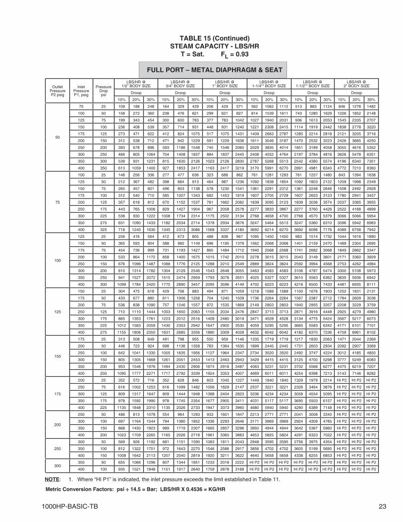
1000HP-BASIC-TB 23
NOTE: 1. Where “HI P1” is indicated, the inlet pressure exceeds the limit established in Table 11.
TABLE 15 (Continued)STEAM CAPACITY - LBS/HR
T = Sat. FL = 0.93
FULL PORT – METAL DIAPHRAGM & SEAT
Metric Conversion Factors: psi ÷ 14.5 = Bar; LBS/HR X 0.4536 = KG/HR
Outlet Pressure P2 psig
Inlet PressureP1, psig
PressureDroppsi
LBS/HR @ 1/2" BODY SIZE
LBS/HR @3/4" BODY SIZE
LBS/HR @1" BODY SIZE
LBS/HR @1-1/4"" BODY SIZE
LBS/HR @1-1/2"" BODY SIZE
LBS/HR @2" BODY SIZE
Droop Droop Droop Droop Droop Droop
10% 20% 30% 10% 20% 30% 10% 20% 30% 10% 20% 30% 10% 20% 30% 10% 20% 30%
50
75 25 109 188 248 164 329 429 206 429 571 562 1062 1112 513 883 1124 846 1278 1482
100 50 158 272 360 238 476 621 299 621 827 814 1539 1611 743 1280 1629 1226 1852 2148
125 75 199 343 454 300 600 783 377 783 1042 1027 1940 2031 936 1613 2053 1545 2335 2707
150 100 236 408 539 357 714 931 448 931 1240 1221 2308 2415 1114 1919 2442 1838 2778 3220
175 125 273 471 622 412 824 1075 517 1075 1431 1409 2663 2787 1285 2214 2818 2121 3205 3716
200 150 312 538 712 471 942 1229 591 1229 1636 1611 3046 3187 1470 2532 3223 2426 3665 4250
250 200 393 678 896 593 1186 1548 745 1548 2060 2029 3835 4014 1851 3189 4058 3055 4616 5352
300 250 466 805 1064 704 1408 1837 884 1837 2445 2408 4552 4764 2197 3784 4816 3626 5478 6351
350 300 539 931 1231 815 1630 2126 1023 2126 2830 2787 5268 5513 2542 4380 5574 4196 6340 7351
400 350 613 1059 1400 927 1853 2417 1163 2417 3219 3170 5991 6270 2891 4981 6340 4772 7210 8360
75
100 25 148 256 336 277 477 636 323 688 862 761 1281 1293 761 1257 1480 843 1394 1638
125 50 212 367 482 398 684 913 464 987 1236 1092 1838 1854 1092 1803 2122 1209 1998 2349
150 75 265 457 601 496 853 1138 578 1230 1541 1361 2291 2312 1361 2248 2646 1508 2492 2928
175 100 312 540 710 585 1007 1343 682 1453 1819 1607 2705 2729 1607 2653 3123 1780 2941 3457
200 125 357 618 812 670 1152 1537 781 1662 2082 1839 3095 3123 1839 3036 3574 2037 3365 3955
250 175 443 765 1006 829 1427 1904 967 2058 2578 2277 3833 3867 2277 3760 4426 2522 4168 4899
300 225 538 930 1222 1008 1734 2314 1175 2502 3134 2768 4658 4700 2768 4570 5379 3066 5066 5954
350 275 631 1090 1433 1182 2034 2714 1378 2934 3676 3247 5464 5513 3247 5360 6310 3596 5942 6983
400 325 718 1240 1630 1345 2313 3086 1568 3337 4180 3692 6214 6270 3692 6096 7176 4089 6758 7942
100
125 25 256 416 564 412 673 805 488 838 967 1095 1450 1450 983 1514 1732 1044 1616 1890
150 50 365 593 804 588 960 1149 696 1195 1378 1562 2068 2068 1401 2159 2470 1489 2304 2695
175 75 454 736 999 731 1193 1427 865 1484 1712 1940 2568 2568 1741 2682 3068 1849 2862 3347
200 100 533 864 1172 858 1400 1675 1015 1742 2010 2278 3015 3015 2043 3149 3601 2171 3360 3929
250 150 676 1096 1487 1088 1776 2125 1288 2210 2549 2889 3824 3824 2592 3994 4568 2753 4262 4984
300 200 810 1314 1782 1304 2129 2546 1543 2648 3055 3463 4583 4583 3106 4787 5474 3300 5108 5973
350 250 941 1527 2072 1515 2474 2959 1793 3078 3551 4025 5327 5327 3610 5563 6362 3835 5936 6942
400 300 1099 1784 2420 1770 2890 3457 2095 3596 4149 4702 6223 6223 4218 6500 7433 4481 6935 8111
125
150 25 304 475 618 429 706 883 494 871 1059 1218 1589 1589 1100 1676 1903 1252 1831 2131
175 50 433 677 880 611 1006 1258 704 1240 1509 1736 2264 2264 1567 2387 2712 1784 2609 3036
200 75 536 838 1090 757 1246 1557 872 1535 1869 2149 2803 2803 1940 2955 3357 2208 3229 3759
250 125 710 1110 1444 1003 1650 2063 1155 2034 2476 2847 3713 3713 2871 3916 4448 2925 4279 4980
300 175 865 1353 1761 1223 2012 2516 1409 2480 3019 3471 4528 4528 3134 4775 5424 3567 5217 6073
350 225 1012 1583 2059 1430 2353 2942 1647 2900 3530 4059 5295 5295 3665 5583 6342 4171 6101 7101
400 275 1155 1806 2350 1631 2685 3356 1880 3309 4028 4632 6042 6042 4182 6370 7236 4759 6961 8102
150
175 25 313 508 649 491 798 955 550 959 1146 1335 1719 1719 1217 1830 2063 1471 2044 2369
200 50 446 723 924 698 1136 1358 783 1364 1630 1899 2445 2445 1731 2603 2934 2092 2907 3369
250 100 642 1041 1330 1005 1635 1956 1127 1964 2347 2734 3520 3520 2492 3747 4224 3012 4185 4850
300 150 805 1305 1668 1261 2051 2453 1413 2463 2943 3429 4415 4415 3125 4700 5298 3777 5249 6083
350 200 953 1546 1976 1494 2430 2906 1674 2918 3487 4063 5231 5231 3702 5568 6277 4475 6219 7207
400 250 1095 1777 2271 1717 2792 3339 1924 3353 4007 4669 6011 6011 4254 6398 7213 5143 7146 8282
175
200 25 352 572 716 352 628 846 603 1045 1227 1449 1840 1840 1329 1979 2214 HI P2 HI P2 HI P2
250 75 616 1002 1253 616 1099 1482 1056 1829 2147 2537 3221 3221 2326 3464 3876 HI P2 HI P2 HI P2
300 125 809 1317 1647 809 1444 1948 1388 2404 2823 3336 4234 4234 3058 4554 5095 HI P2 HI P2 HI P2
350 175 978 1592 1990 978 1745 2354 1677 2905 3411 4031 5117 5117 3695 5503 6157 HI P2 HI P2 HI P2
400 225 1135 1848 2310 1135 2026 2733 1947 3373 3960 4680 5940 5940 4290 6389 7148 HI P2 HI P2 HI P2
200
250 50 486 813 1078 554 964 1293 933 1601 1847 2213 2771 2771 2041 3008 3340 HI P2 HI P2 HI P2
300 100 697 1164 1544 794 1380 1852 1336 2293 2646 3171 3969 3969 2924 4309 4785 HI P2 HI P2 HI P2
350 150 868 1450 1923 989 1719 2307 1665 2857 3296 3950 4944 4944 3642 5367 5960 HI P2 HI P2 HI P2
400 200 1023 1709 2265 1165 2026 2718 1961 3365 3883 4653 5825 5824 4291 6323 7022 HI P2 HI P2 HI P2
250
300 50 569 926 1192 681 1151 1590 1083 1811 2043 2948 3595 3595 2756 3975 4354 HI P2 HI P2 HI P2
350 100 812 1322 1701 972 1643 2270 1546 2586 2917 3856 4702 4702 3605 5199 5695 HI P2 HI P2 HI P2
400 150 1008 1642 2113 1207 2040 2819 1920 3211 3622 4640 5658 5658 4338 6255 6853 HI P2 HI P2 HI P2
300350 50 655 1066 1296 807 1344 1851 1233 2018 2222 HI P2 HI P2 HI P2 HI P2 HI P2 HI P2 HI P2 HI P2 HI P2
400 100 935 1521 1848 1151 1917 2640 1759 2878 3168 HI P2 HI P2 HI P2 HI P2 HI P2 HI P2 HI P2 HI P2 HI P2
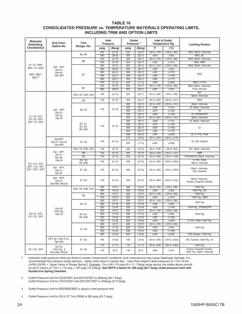
24 1000HP-BASIC-TB
TABLE 16CONSOLIDATED PRESSURE vs. TEMPERATURE MATERIALS OPERATING LIMITS,
INCLUDING TRIM AND OPTION LIMITS
1 Indicated outlet pressure limits are those to contain overpressure conditions; such overpressure may cause diaphragm damage. It is recommended that pressure safety devices – safety relief valve or rupture disc – have their setpoint relief pressures at 110% of the UVRS (UVRS = “Upper Value of Range Spring”). Example: For a 90–170 psig (6.2–11.7 Barg) range spring, the safety device should be set to relieve at 110% x 170 psig = 187 psig (12.9 Barg). See NOTE 2 below for 300 psig (20.7 barg) outlet pressure limit with Ductile Iron Spring Chamber.
2 Outlet Pressure Limit for CS/DI/SST and SST/DI/SST is 300psig (20.7 barg). Outlet Pressure Limit for CS/CS/SST and SST/SST/SST is 400psig (27.6 barg).
3 Outlet Pressure Limit for BRZ/BRZ/BRZ is equal to inlet pressure limit.
4 Outlet Pressure Limit for S5 & S7 Trim (FKM) is 300 psig (20.7 barg)
MaterialsBody/Sprg.
Chamber/Cyl
End Conn. Option No.
Trim Design. No.
Inlet Pressure
Outlet Pressure 1
Inlet & Outlet Temperature Rg Limiting Portion
psig (Barg) psig (Barg) °F (°C)
DI / DI / BRZBRZ / DI / BRZ
BRZ / BRZ / BRZ 3
Std. - NPTOpt-31,Opt-45,Opt-46G
B2, B3400 (27.6) 300 (20.7) -20 to +150 (-29 to +66) BRZ, Mech. Internals390 (26.9) 300 (20.7) +200 (+93) BRZ, BC
BB400 (27.6) 300 (20.7) -20 to +150 (-29 to +66) BRZ, Mech. Internals400 (27.6) 300 (20.7) +250 (+121) BRZ, NBR
B1
400 (27.6) 300 (20.7) -20 to +150 (-29 to +66) BRZ, Mech. Internals385 (26.6) 300 (20.7) +200 (+94)
BRZ365 (25.2) 300 (20.7) +250 (+121)335 (23.1) 300 (20.7) +300 (+149)300 (20.7) 300 (20.7) +350 (+177)250 (17.2) 250 (17.2) +400 (+205) BRZ, V-TFE
B5400 (27.6) 300 (20.7) -20 to +150 (-29 to +66) BRZ, Mech. Internals,
Phos. Bronze385 (26.6) 300 (20.7) +200 (+94)
DI / DI / SSTCS / DI / SSTSST / DI / SST
Std. - NPTOpt-31,Opt-32,Opt-45
S2N, S3, S3N, S40 740 (51.0) 300 (20.7) -20 to +200 (-29 to +93)BC
Mech. Internals
SB 740 (51.0) 300 (20.7) -20 to +250 (-29 to +121) NBR
S6, S7 740 (51.0)
300 (20.7) -20 to +250 (-29 to +121) Mech. Internals300 (20.7) +268 (+131) DI, Mech. Internals300 (20.7) +275 (+135) DI300 (20.7) +300 (+149) DI, EPDM/EPR
S0, S1,S2, S5,S9, S36
740 (51.0)
300 (20.7) -20 to +250 (-29 to +121) Mech. Internals300 (20.7) +268 (+131) DI, Mech. Internals300 (20.7) +275 (+135)
DI300 (20.7) +300 (+149)300 (20.7) +350 (+177)295 (20.3) +400 (+205) DI, V-TFE, FKM
Std-NPTOpt-31, Opt-32
Opt-46GS1, S2 740 (51.0)
270 (18.6) -20 to +425 (-29 to +219)
DI, Std. Gasket250 (17.2) +450 (+232)
CS / CS / SSTSST / CS / SSTSST / SST / SST
Std. - NPT,Opt-31,Opt-32,Opt-45
S2N, S3, S3N, S40 740 (51.0) 400 (27.6) -20 to +200 (-29 to +93) BC, Mech. Internals
SB 740 (51.0) 400 (27.6) -20 to +250 (-29 to +121) NBR
S6 740 (51.0) 400 (27.6) -20 to +300 (-29 to +149) EPDM/EPR, Mech. Internals
SO, S5S9, S36
740 (51.0) 400 (27.6) -20 to +400 (-29 to +205)V-TFE, FKM,
Mech. Internals
Std. - NPT,Opt-31,Opt-32,
S1, S2 740 (51.0) 400 (27.6) -20 to +450 (-29 to +232)Mech. Internals,
Std. Gaskets
Std. - NPT,Opt-31,
Opt-46G (Req'd)S1, S2 740 (51.0) 400 (27.6) -20 to +600 (-29 to +315)
Mech. Internals,Carbon Graphite Gasket
CS/ DI / SSTCS / CS / SST
Opt-30,150# Flg.,
Opt-45
S2N, S3, S3N, S40285 (19.7) 285 (19.7) -20 to +100 (-29 to +38) 150# Flg.265 (18.3) 265 (18.3) +200 (+93) 150# Flg., BC
SB285 (19.7) 285 (19.7) -20 to +100 (-29 to +38) 150# Flg.245 (16.9) 265 (18.3) +250 (+121) 150# Flg., NBR
S6, S7285 (19.7) 285 (19.7) -20 to +100 (-29 to +38)
150# Flg.260 (17.9) 260 (17.9) +200 (+94)230 (15.9) 230 (15.9) +300 (+149) 150# Flg., EPDM/EPR
S0, S5,S9, S36
285 (19.7) 285 (19.7) -20 to +100 (-29 to +38)150# Flg.260 (17.9) 260 (17.9) +200 (+94)
230 (15.9) 230 (15.9) +300 (+149)200 (13.8) 200 (13.8) +400 (+205) V-TFE, FKM, 150# Flg.
S1, S2
285 (19.7) 285 (19.7) -20 to +100 (-29 to +38)150# Flg.260 (17.9) 260 (19.9) +200 (+94)
230 (15.9) 230 (15.9) +300 (+149)200 (13.8) 200 (13.8) +400 (+205) TFE Gasket, 150# Flg.
OPT-30, 150# FLG., Opt-46G
S1, S2 185 (12.8) 185 (12.8) -20 to +450 (-29 to +232) Std. Gasket, 150# Flg., DI
CS / CS / SSTOpt-30,
150# Flg., & Opt-46G (Req'd)
S1, S2
170 (11.7) 170 (11.7) -20 to +500 (-29 to +260) 150# Flg.
140 (9.7) 140 (9.7) +600 (315)Carbon Graphite Gasket,150# Flg., Mech. Internals
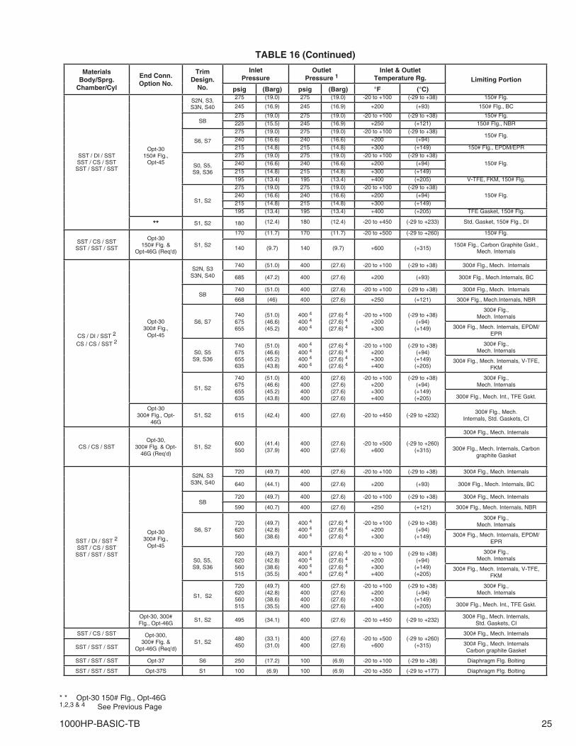
1000HP-BASIC-TB 25
* * Opt-30 150# Flg., Opt-46G 1,2,3 & 4 See Previous Page
MaterialsBody/Sprg.
Chamber/Cyl
End Conn.Option No.
TrimDesign.
No.
InletPressure
OutletPressure 1
Inlet & OutletTemperature Rg. Lim it ing Portion
psig (Barg) psig (Barg) °F (°C)
SST / DI / SSTSST / CS / SSTSST / SST / SST
Opt-30150# Flg.,
Opt-45
S2N, S3, S3N, S40
275 (19.0) 275 (19.0) -20 to +100 (-29 to +38) 150# Flg.
245 (16.9) 245 (16.9) +200 (+93) 150# Flg., BC
SB275 (19.0) 275 (19.0) -20 to +100 (-29 to +38) 150# Flg.225 (15.5) 245 (16.9) +250 (+121) 150# Flg., NBR
S6, S7
275 (19.0) 275 (19.0) -20 to +100 (-29 to +38)150# Flg.
240 (16.6) 240 (16.6) +200 (+94)215 (14.8) 215 (14.8) +300 (+149) 150# Flg., EPDM/EPR
S0, S5,S9, S36
275 (19.0) 275 (19.0) -20 to +100 (-29 to +38)150# Flg.240 (16.6) 240 (16.6) +200 (+94)
215 (14.8) 215 (14.8) +300 (+149)195 (13.4) 195 (13.4) +400 (+205) V-TFE, FKM, 150# Flg.
S1, S2
275 (19.0) 275 (19.0) -20 to +100 (-29 to +38)150# Flg.240 (16.6) 240 (16.6) +200 (+94)
215 (14.8) 215 (14.8) +300 (+149)195 (13.4) 195 (13.4) +400 (+205) TFE Gasket, 150# Flg.
** S1, S2 180 (12.4) 180 (12.4) -20 to +450 (-29 to +233) Std. Gasket, 150# Flg., DI
SST / CS / SSTSST / SST / SST
Opt-30150# Flg. &
Opt-46G (Req'd)S1, S2
170 (11.7) 170 (11.7) -20 to +500 (-29 to +260) 150# Flg.
140 (9.7) 140 (9.7) +600 (+315)150# Flg., Carbon Graphite Gskt.,
Mech. Internals
CS / DI / SST 2
CS / CS / SST 2
Opt-30300# Flg.,
Opt-45
S2N, S3S3N, S40
740 (51.0) 400 (27.6) -20 to +100 (-29 to +38) 300# Flg., Mech. Internals
685 (47.2) 400 (27.6) +200 (+93) 300# Flg., Mech.Internals, BC
SB740 (51.0) 400 (27.6) -20 to +100 (-29 to +38) 300# Flg., Mech. Internals
668 (46) 400 (27.6) +250 (+121) 300# Flg., Mech.Internals, NBR
S6, S7740675655
(51.0)(46.6)(45.2)
400 4
400 4
400 4
(27.6) 4
(27.6) 4
(27.6) 4
-20 to +100+200+300
(-29 to +38)(+94)
(+149)
300# Flg.,Mech. Internals
300# Flg., Mech. Internals, EPDM/EPR
S0, S5S9, S36
740675655635
(51.0)(46.6)(45.2)(43.8)
400 4
400 4
400 4
400 4
(27.6) 4
(27.6) 4
(27.6) 4
(27.6) 4
-20 to +100+200+300+400
(-29 to +38)(+94)
(+149)(+205)
300# Flg.,Mech. Internals
300# Flg., Mech. Internals, V-TFE, FKM
S1, S2
740675655635
(51.0)(46.6)(45.2)(43.8)
400400400400
(27.6)(27.6)(27.6)(27.6)
-20 to +100+200+300+400
(-29 to +38)(+94)
(+149)(+205)
300# Flg.,Mech. Internals
300# Flg., Mech. Int., TFE Gskt.
Opt-30300# Flg., Opt-
46GS1, S2 615 (42.4) 400 (27.6) -20 to +450 (-29 to +232)
300# Flg., Mech.Internals, Std. Gaskets, CI
CS / CS / SSTOpt-30,
300# Flg. & Opt-46G (Req'd)
S1, S2600550
(41.4)(37.9)
400400
(27.6)(27.6)
-20 to +500+600
(-29 to +260)(+315)
300# Flg., Mech. Internals
300# Flg., Mech. Internals, Carbon graphite Gasket
SST / DI / SST 2
SST / CS / SSTSST / SST / SST
Opt-30300# Flg.,
Opt-45
S2N, S3S3N, S40
720 (49.7) 400 (27.6) -20 to +100 (-29 to +38) 300# Flg., Mech. Internals
640 (44.1) 400 (27.6) +200 (+93) 300# Flg., Mech. Internals, BC
SB720 (49.7) 400 (27.6) -20 to +100 (-29 to +38) 300# Flg., Mech. Internals
590 (40.7) 400 (27.6) +250 (+121) 300# Flg., Mech. Internals, NBR
S6, S7720620560
(49.7)(42.8)(38.6)
400 4
400 4
400 4
(27.6) 4
(27.6) 4
(27.6) 4
-20 to +100+200+300
(-29 to +38)(+94)
(+149)
300# Flg.,Mech. Internals
300# Flg., Mech. Internals, EPDM/EPR
S0, S5,S9, S36
720620560515
(49.7)(42.8)(38.6)(35.5)
400 4
400 4
400 4
400 4
(27.6) 4
(27.6) 4
(27.6) 4
(27.6) 4
-20 to + 100+200+300+400
(-29 to +38)(+94)
(+149)(+205)
300# Flg.,Mech. Internals
300# Flg., Mech. Internals, V-TFE, FKM
S1, S2
720620560515
(49.7)(42.8)(38.6)(35.5)
400400400400
(27.6)(27.6)(27.6)(27.6)
-20 to +100+200+300+400
(-29 to +38)(+94)
(+149)(+205)
300# Flg.,Mech. Internals
300# Flg., Mech. Int., TFE Gskt.
Opt-30, 300#Flg., Opt-46G
S1, S2 495 (34.1) 400 (27.6) -20 to +450 (-29 to +232)300# Flg., Mech. Internals,
Std. Gaskets, CI
SST / CS / SST Opt-300,300# Flg. &
Opt-46G (Req'd)S1, S2
480450
(33.1)(31.0)
400400
(27.6)(27.6)
-20 to +500+600
(-29 to +260)(+315)
300# Flg., Mech. Internals
SST / SST / SST300# Flg., Mech. InternalsCarbon graphite Gasket
SST / SST / SST Opt-37 S6 250 (17.2) 100 (6.9) -20 to +100 (-29 to +38) Diaphragm Flg. Bolting
SST / SST / SST Opt-37S S1 100 (6.9) 100 (6.9) -20 to +350 (-29 to +177) Diaphragm Flg. Bolting
TABLE 16 (Continued)
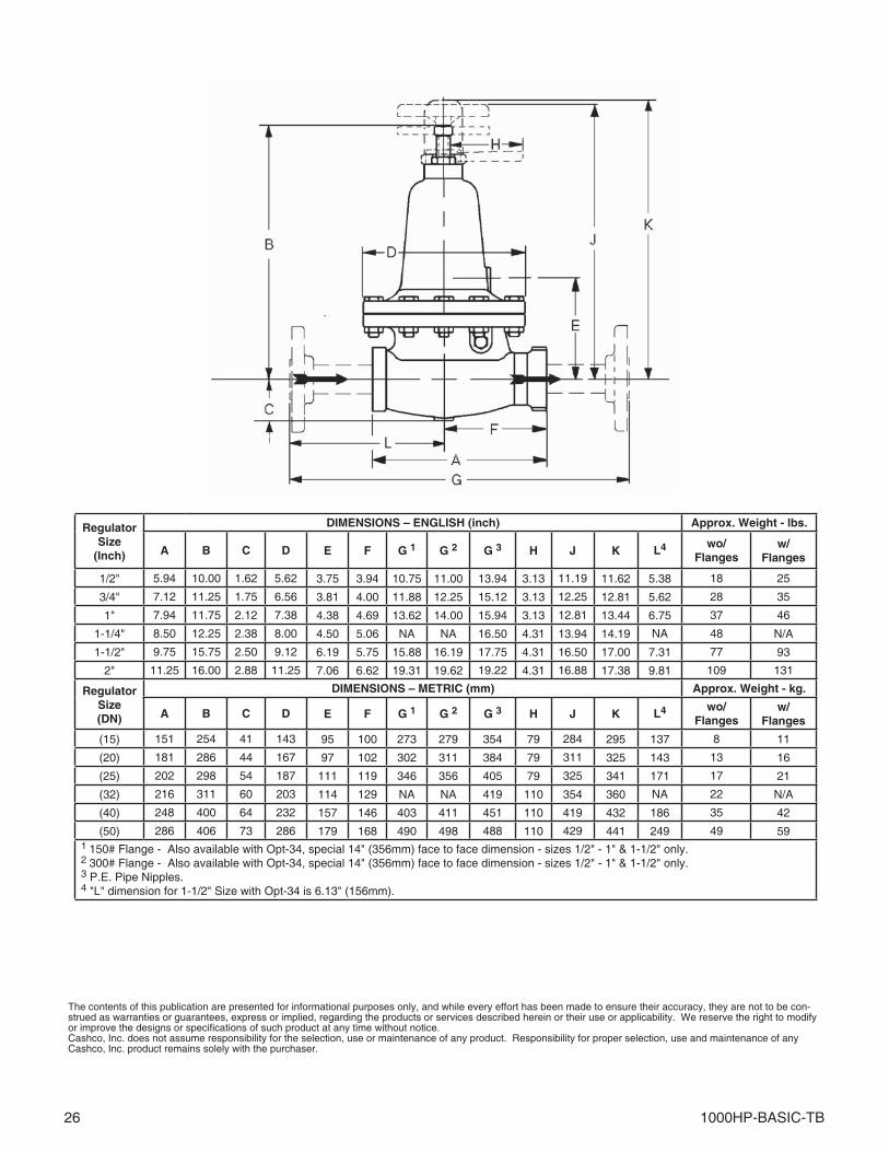
26 1000HP-BASIC-TB
RegulatorSize
(Inch)
DIMENSIONS – ENGLISH (inch) Approx. Weight - lbs.
A B C D E F G 1 G 2 G 3 H J K L4 wo/Flanges
w/Flanges
1/2" 5.94 10.00 1.62 5.62 3.75 3.94 10.75 11.00 13.94 3.13 11.19 11.62 5.38 18 25
3/4" 7.12 11.25 1.75 6.56 3.81 4.00 11.88 12.25 15.12 3.13 12.25 12.81 5.62 28 35
1" 7.94 11.75 2.12 7.38 4.38 4.69 13.62 14.00 15.94 3.13 12.81 13.44 6.75 37 46
1-1/4" 8.50 12.25 2.38 8.00 4.50 5.06 NA NA 16.50 4.31 13.94 14.19 NA 48 N/A
1-1/2" 9.75 15.75 2.50 9.12 6.19 5.75 15.88 16.19 17.75 4.31 16.50 17.00 7.31 77 93
2" 11.25 16.00 2.88 11.25 7.06 6.62 19.31 19.62 19.22 4.31 16.88 17.38 9.81 109 131
RegulatorSize(DN)
DIMENSIONS – METRIC (mm) Approx. Weight - kg.
A B C D E F G 1 G 2 G 3 H J K L4 wo/Flanges
w/Flanges
(15) 151 254 41 143 95 100 273 279 354 79 284 295 137 8 11
(20) 181 286 44 167 97 102 302 311 384 79 311 325 143 13 16
(25) 202 298 54 187 111 119 346 356 405 79 325 341 171 17 21
(32) 216 311 60 203 114 129 NA NA 419 110 354 360 NA 22 N/A
(40) 248 400 64 232 157 146 403 411 451 110 419 432 186 35 42
(50) 286 406 73 286 179 168 490 498 488 110 429 441 249 49 591 150# Flange - Also available with Opt-34, special 14" (356mm) face to face dimension - sizes 1/2" - 1" & 1-1/2" only.2 300# Flange - Also available with Opt-34, special 14" (356mm) face to face dimension - sizes 1/2" - 1" & 1-1/2" only.3 P.E. Pipe Nipples.4 "L" dimension for 1-1/2" Size with Opt-34 is 6.13" (156mm).
The contents of this publication are presented for informational purposes only, and while every effort has been made to ensure their accuracy, they are not to be con-strued as warranties or guarantees, express or implied, regarding the products or services described herein or their use or applicability. We reserve the right to modify or improve the designs or specifications of such product at any time without notice.Cashco, Inc. does not assume responsibility for the selection, use or maintenance of any product. Responsibility for proper selection, use and maintenance of any Cashco, Inc. product remains solely with the purchaser.
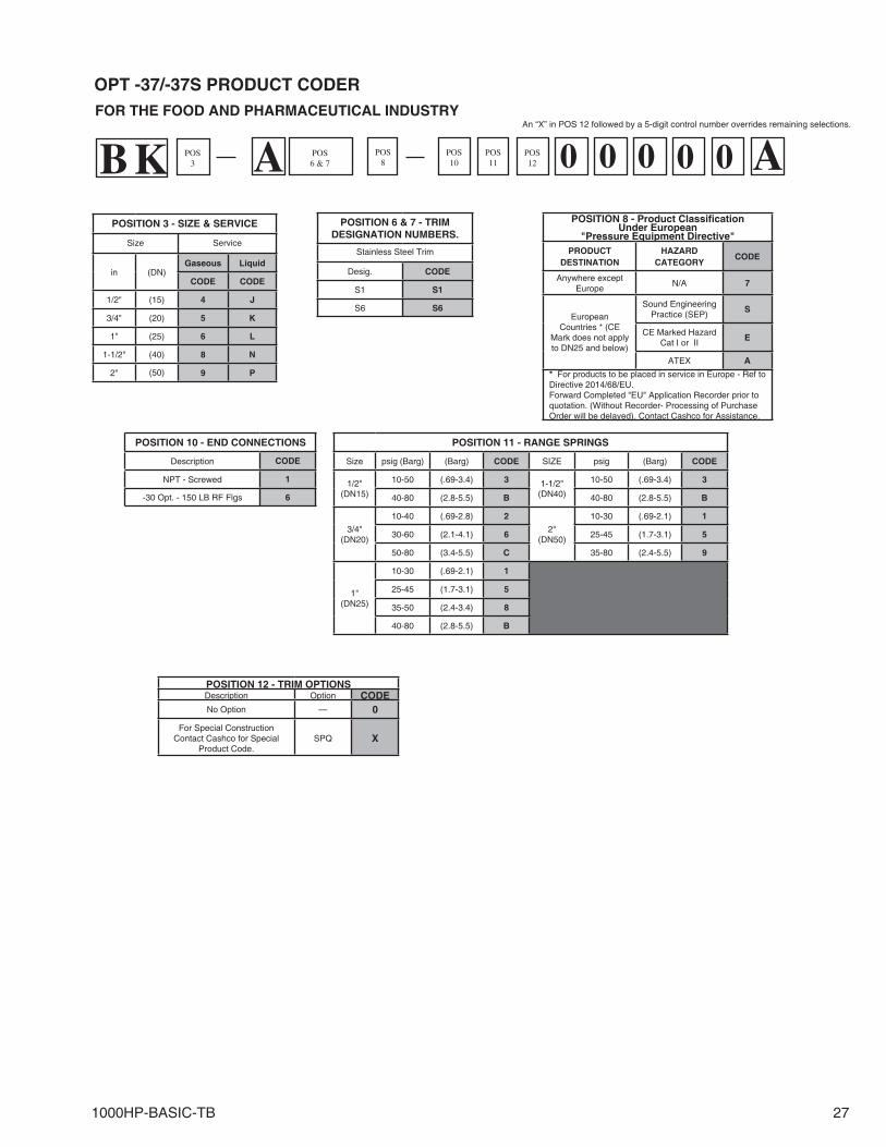
1000HP-BASIC-TB 27
BKPOSITION 3 - SIZE & SERVICE
Size Service
in (DN)Gaseous Liquid
CODE CODE
1/2" (15) 4 J
3/4" (20) 5 K
1" (25) 6 L
1-1/2" (40) 8 N
2" (50) 9 P
POSITION 6 & 7 - TRIM DESIGNATION NUMBERS.
Stainless Steel Trim
Desig. CODE
S1 S1
S6 S6
POSITION 10 - END CONNECTIONS
Description CODE
NPT - Screwed 1
-30 Opt. - 150 LB RF Flgs 6
POSITION 11 - RANGE SPRINGS
Size psig (Barg) (Barg) CODE SIZE psig (Barg) CODE
1/2"(DN15)
10-50 (.69-3.4) 3 1-1/2"(DN40)
10-50 (.69-3.4) 3
40-80 (2.8-5.5) B 40-80 (2.8-5.5) B
3/4"(DN20)
10-40 (.69-2.8) 2
2"(DN50)
10-30 (.69-2.1) 1
30-60 (2.1-4.1) 6 25-45 (1.7-3.1) 5
50-80 (3.4-5.5) C 35-80 (2.4-5.5) 9
1"(DN25)
10-30 (.69-2.1) 1
25-45 (1.7-3.1) 5
35-50 (2.4-3.4) 8
40-80 (2.8-5.5) B
OPT -37/-37S PRODUCT CODER
APOS3
POS10
POS6 & 7
POS11
POS12
POS8 0 0 0 0 0A
FOR THE FOOD AND PHARMACEUTICAL INDUSTRY
POSITION 8 - Product Classifi cationUnder European
"Pressure Equipment Directive" PRODUCT
DESTINATIONHAZARD
CATEGORYCODE
Anywhere except Europe
N/A 7
EuropeanCountries * (CE
Mark does not apply to DN25 and below)
Sound Engineering Practice (SEP)
S
CE Marked Hazard Cat I or II
E
ATEX A
* For products to be placed in service in Europe - Ref to Directive 2014/68/EU. Forward Completed "EU" Application Recorder prior to quotation. (Without Recorder- Processing of Purchase Order will be delayed). Contact Cashco for Assistance.
POSITION 12 - TRIM OPTIONSDescription Option CODENo Option — 0
For Special ConstructionContact Cashco for Special
Product Code.SPQ X
An “X” in POS 12 followed by a 5-digit control num ber over rides remaining selections.
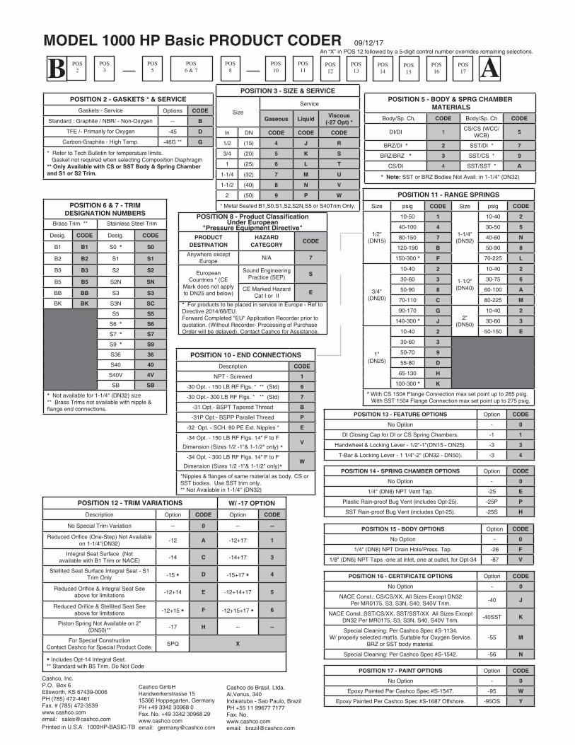
ABMODEL 1000 HP Basic PRODUCT CODER 09/12/17
POSITION 2 - GASKETS * & SERVICE
Gaskets - Service Options CODE
Standard : Graphite / NBR/ - Non-Oxygen -- B
TFE /- Primarily for Oxygen -45 D
Carbon-Graphite - High Temp. -46G ** G
* Refer to Tech Bulletin for temperature limits. Gasket not required when selecting Composition Diaphragm** Only Available with CS or SST Body & Spring Chamberand S1 or S2 Trim.
POSITION 3 - SIZE & SERVICE
Size
Service
Gaseous LiquidViscous
(-27 Opt) *
In DN CODE CODE CODE
1/2 (15) 4 J R
3/4 (20) 5 K S
1 (25) 6 L T
1-1/4 (32) 7 M U
1-1/2 (40) 8 N V
2 (50) 9 P W
* Metal Seated B1,S0,S1,S2,S2N,S5 or S40Trim Only.
POSITION 5 - BODY & SPRG CHAMBER MATERIALS
Body/Sp. Ch. CODE Body/Sp. Ch CODE
DI/DI 1CS/CS (WCC/
WCB)5
BRZ/DI * 2 SST/DI * 7
BRZ/BRZ * 3 SST/CS * 9
CS/DI 4 SST/SST * A
* Note: SST or BRZ Bodies Not Avail. in 1-1/4" (DN32)
POSITION 11 - RANGE SPRINGS
Size psig CODE Size psig CODE
1/2"(DN15)
10-50 1
1-1/4"(DN32)
10-40 2
40-100 4 30-50 5
80-150 7 40-60 N
120-190 B 50-90 8
150-300 * F 70-225 L
3/4"(DN20)
10-40 2
1-1/2"(DN40)
10-40 2
30-60 3 30-75 6
50-90 8 60-100 A
70-110 C 80-225 M
90-170 G2"
(DN50)
10-40 2
140-300 * J 30-60 3
1"(DN25)
10-40 2 50-150 E
30-60 3
50-70 9
55-80 D
65-130 H
100-300 * K
* With CS 150# Flange Connection max set point up to 285 psig. With SST 150# Flange Connection max set point up to 275 psig.
POSITION 10 - END CONNECTIONS
Description CODE
NPT - Screwed 1
-30 Opt. - 150 LB RF Flgs. * ** (Std) 6
-30 Opt.- 300 LB RF Flgs. * ** (Std) 7
-31 Opt.- BSPT Tapered Thread B
-31P Opt.- BSPP Parallel Thread P
-32 Opt. - SCH. 80 PE Ext. Nipples * E
-34 Opt. - 150 LB RF Flgs. 14" F to F
Dimension (Sizes 1/2 -1"& 1-1/2" only) *V
-34 Opt. - 300 LB RF Flgs. 14" F to F
Dimension (Sizes 1/2 -1"& 1-1/2" only)*W
*Nipples & flanges of same material as body. CS or SST bodies. Use SST trim only.** Not Available in 1-1/4" (DN32)
POSITION 15 - BODY OPTIONS Option CODE
No Option - 0
1/4" (DN8) NPT Drain Hole/Press. Tap. -26 F
1/8" (DN6) NPT Taps -one at inlet, one at outlet, for Opt-34 -87 V
POSITION 16 - CERTIFICATE OPTIONS Option CODE
No Option - 0
NACE Const.: CS/CS/XX, All Sizes Except DN32Per MR0175, S3, S3N, S40, S40V Trim.
-40 J
NACE Const.:SST/CS/XX, SST/SST/XX All Sizes Except DN32 Per MR0175, S3, S3N, S40, S40V Trim.
-40SST K
Special Cleaning: Per Cashco Spec #S-1134.W/ properly selected mat'ls. Suitable for Oxygen Service.
BRZ or SST body material.-55 M
Special Cleaning: Per Cashco Spec.#S-1542. -56 N
POSITION 17 - PAINT OPTIONS Option CODE
No Option - 0
Epoxy Painted Per Cashco Spec #S-1547. -95 W
Epoxy Painted Per Cashco Spec #S-1687 Offshore. -95OS Y
POSITION 14 - SPRING CHAMBER OPTIONS Option CODE
No Option - 0
1/4" (DN8) NPT Vent Tap. -25 E
Plastic Rain-proof Bug Vent (includes Opt-25). -25P P
SST Rain-proof Bug Vent (includes Opt-25). -25S H
POSITION 12 - TRIM VARIATIONS W/ -17 OPTION
Description Option CODE Option CODE
No Special Trim Variation -- 0 -- --
Reduced Orifi ce (One-Step) Not Available on 1-1/4"(DN32)
-12 A -12+17 1
Integral Seat Surface (Notavailable with B1 Trim or NACE)
-14 C -14+17 3
Stellited Seat Surface Integral Seat - S1 Trim Only -15 * D -15+17 * 4
Reduced Orifi ce & Integral Seat See above for limitations
-12+14 E -12+14+17 5
Reduced Orifi ce & Stellited Seat See above for limitations -12+15 * F -12+15+17 * 6
Piston Spring Not Available on 2" (DN50)**
-17 H -- --
For Special ConstructionContact Cashco for Special Product Code.
SPQ X
* Includes Opt-14 In te gral Seat.** Standard with B5 Trim. Do Not Code
POS2
POS3
POS5
POS6 & 7
POS8
POS10
POS11
POS12
POS13
POS14
POS15
POS16
POS17
POSITION 6 & 7 - TRIMDESIGNATION NUMBERS
Brass Trim ** Stainless Steel Trim
Desig. CODE Desig. CODE
B1 B1 S0 * S0
B2 B2 S1 S1
B3 B3 S2 S2
B5 B5 S2N SN
BB BB S3 S3
BK BK S3N SC
S5 S5
S6 * S6
S7 * S7
S9 * S9
S36 36
S40 40
S40V 4V
SB SB
* Not available for 1-1/4" (DN32) size** Brass Trims not available with nipple & flange end connections.
POSITION 8 - Product Classifi cationUnder European
"Pressure Equipment Directive" PRODUCT
DESTINATIONHAZARD
CATEGORYCODE
Anywhere except Europe
N/A 7
EuropeanCountries * (CE
Mark does not apply to DN25 and below)
Sound Engineering Practice (SEP)
S
CE Marked Hazard Cat I or II
E
* For products to be placed in service in Europe - Ref to Directive 2014/68/EU. Forward Completed "EU" Application Recorder prior to quotation. (Without Recorder- Processing of Purchase Order will be delayed). Contact Cashco for Assistance.
Cashco, Inc.P.O. Box 6 Ellsworth, KS 67439-0006PH (785) 472-4461Fax. # (785) 472-3539www.cashco.comemail: [email protected] in U.S.A. 1000HP-BASIC-TB
Cashco do Brasil, Ltda.Al.Venus, 340Indaiatuba - Sao Paulo, BrazilPH +55 11 99677 7177Fax. No. www.cashco.comemail: [email protected]
An “X” in POS 12 followed by a 5-digit control num ber over rides remaining selections.
POSITION 13 - FEATURE OPTIONS Option CODE
No Option - 0
DI Closing Cap for DI or CS Spring Chambers. -1 1
Handwheel & Locking Lever - 1/2"-1"(DN15 - DN25). -3 3
T-Bar & Locking Lever - 1 1/4"-2" (DN32 - DN50). -3 4
Cashco GmbHHandwerkerstrasse 1515366 Hoppegarten, GermanyPH +49 3342 30968 0Fax. No. +49 3342 30968 29www.cashco.comemail: [email protected]