Embed Size (px)
Citation preview
© ISO 2004 — All rights reserved
ISO TC 67/SC 4
Date: 2004-03-15
ISO/FDIS 17078-1:2004(E)
ISO TC 67/SC 4/WG
Secretariat: API/ANSI
Petroleum and natural gas industries — Drilling and production equipment — Part 1: Side-pocket mandrels
Élément introductif — Élément central — Partie 1: Titre de la partie
Document type: International StandardDocument subtype: Document stage: (50) ApprovalDocument language: E
/tt/file_convert/5e8066c3981498699412b13a/document.doc STD Version 2.1
ISO/FDIS 17078-1:2004(E)
Copyright notice
This ISO document is a Draft International Standard and is copyright-protected by ISO. Except as permitted under the applicable laws of the user's country, neither this ISO draft nor any extract from it may be reproduced, stored in a retrieval system or transmitted in any form or by any means, electronic, photocopying, recording or otherwise, without prior written permission being secured.
Requests for permission to reproduce should be addressed to either ISO at the address below or ISO's member body in the country of the requester.
ISO copyright officeCase postale 56 CH-1211 Geneva 20Tel. + 41 22 749 01 11Fax + 41 22 749 09 47E-mail [email protected] www.iso.org
Reproduction may be subject to royalty payments or a licensing agreement.
Violators may be prosecuted.
II
ISO/FDIS 17078-1:2004(E)
Contents
Foreword..................................................................................................................................................... vi
Introduction............................................................................................................................................... vii
1 Scope................................................................................................................................................... 12 Normative references.........................................................................................................................13 Terms and definitions......................................................................................................................... 2
4 Abbreviated terms........................................................................................................................... 6
5 Functional specification.....................................................................................................................75.1 General................................................................................................................................................. 75.2 Functional characteristics.................................................................................................................. 75.3 Well parameters.................................................................................................................................. 75.3.1 General................................................................................................................................................. 75.3.2 Well fluid parameters.......................................................................................................................... 75.3.3 Well physical parameters................................................................................................................... 75.3.4 Allowable well operations.................................................................................................................. 85.3.5 Corrosion information........................................................................................................................85.4 Operational parameters......................................................................................................................85.5 Compatibility with related well devices.............................................................................................95.5.1 General................................................................................................................................................. 95.5.2 Polished bore dimensions..................................................................................................................95.6 Environmental service classes..........................................................................................................95.7 Design validation................................................................................................................................ 95.8 Product functional testing grades.....................................................................................................95.9 Quality control grades...................................................................................................................... 105.10 Additional requirements................................................................................................................... 106 Technical specification..................................................................................................................... 106.1 General............................................................................................................................................... 106.2 Technical characteristics................................................................................................................. 106.2.1 Criteria............................................................................................................................................... 106.2.2 Flow control device........................................................................................................................... 106.2.3 Functional requirements.................................................................................................................. 106.2.4 Safe tool passage.............................................................................................................................. 106.2.5 Corrosion requirements................................................................................................................... 106.2.6 Operating parameters....................................................................................................................... 116.2.7 Other tools in annulus...................................................................................................................... 116.2.8 Auxiliary connections....................................................................................................................... 116.3 Design criteria................................................................................................................................... 116.3.1 General............................................................................................................................................... 116.3.2 Material environmental service class..............................................................................................116.3.3 Sealing bore diameters..................................................................................................................... 116.3.4 Maximum drift OD............................................................................................................................. 126.3.5 Temperature effects on the various tensile, compressive, and bending loads...........................126.3.6 Elastomers and non-metallics.........................................................................................................126.3.7 Tensile and compressive loads.......................................................................................................126.3.8 Performance rating........................................................................................................................... 126.3.9 Design methods................................................................................................................................ 126.4 Design verification............................................................................................................................ 136.5 Allowable design changes...............................................................................................................136.5.1 General............................................................................................................................................... 13
III
ISO/FDIS 17078-1:2004(E)
6.6 Design validation requirements.......................................................................................................136.6.1 General............................................................................................................................................... 136.6.2 Design validation.............................................................................................................................. 136.6.3 Design validation grade.................................................................................................................... 136.6.4 Optional design validation testing...................................................................................................146.7 Product functional testing requirements........................................................................................146.7.1 General............................................................................................................................................... 146.7.2 Product functional testing grade.....................................................................................................146.7.3 Optional product functional testing................................................................................................147 Supplier/manufacturer requirements..............................................................................................147.1 General............................................................................................................................................... 147.2 Documentation and data control.....................................................................................................147.2.1 General............................................................................................................................................... 147.2.2 User/purchaser documentation.......................................................................................................157.2.3 Technical/operations manual...........................................................................................................167.3 Product identification requirements................................................................................................167.3.1 General............................................................................................................................................... 167.3.2 Product identification....................................................................................................................... 167.3.3 Traceability........................................................................................................................................ 177.4 Quality control requirements...........................................................................................................177.4.1 General............................................................................................................................................... 177.4.2 Quality control personnel qualifications.........................................................................................177.4.3 Manufacturing non-conformance....................................................................................................177.4.4 Quality control grade selection........................................................................................................177.4.5 Calibration......................................................................................................................................... 18Measuring/testing equipment calibration....................................................................................................187.4.6 Material certifications.......................................................................................................................197.5 Heat treatment requirements...........................................................................................................197.6 Welding requirements......................................................................................................................207.6.1 General............................................................................................................................................... 207.6.2 Welding consumables...................................................................................................................... 207.6.3 Welding procedures/qualification records......................................................................................207.6.4 Welder/welding operator performance qualification......................................................................207.7 Non-destructive examination (NDE) requirements........................................................................207.7.1 General............................................................................................................................................... 207.7.2 NDE personnel qualification............................................................................................................217.7.3 NDE personnel qualification records..............................................................................................217.7.4 Visual examination personnel qualifications..................................................................................217.7.5 Hardness examinations.................................................................................................................... 217.7.6 Radiographic examinations.............................................................................................................217.7.7 Ultrasonic examinations................................................................................................................... 217.7.8 Magnetic particle examinations.......................................................................................................217.7.9 Liquid penetrant examination..........................................................................................................227.7.10 Component dimensional examination.............................................................................................227.7.11 NDE evaluations................................................................................................................................ 227.8 Storage and shipping preparation...................................................................................................227.8.1 General............................................................................................................................................... 227.8.2 Draining, cleaning, and/or drying....................................................................................................227.8.3 Threaded connections and packing bores.....................................................................................227.8.4 Painting of side-pocket mandrels....................................................................................................227.8.5 Permanent marking prior to coating...............................................................................................237.9 Repair................................................................................................................................................. 23
Annex A (normative) Environmental service requirements..............................................24A.1 Purpose.............................................................................................................................................. 24A.1.1 General............................................................................................................................................... 24A.1.2 Class E1: Standard service.............................................................................................................24A.1.3 Class E2: Sulfide stress cracking or H2S (sour) service...............................................................24A.1.4 Class E3: CO2 service...................................................................................................................... 24A.1.5 Class E4: Special service (to be defined by user/purchaser).......................................................25
IV © ISO 2004 — All rights reserved
ISO/FDIS 17078-1:2004(E)
Annex B (normative) Design validation requirements........................................................26B.1 Purpose.............................................................................................................................................. 26B.1.1 General............................................................................................................................................... 26B.1.2 Grade V3: Basic level or grade of side-pocket mandrel design validation/................................27B.1.3 Grade V2: Intermediate level or grade of side-pocket mandrel design validation/....................28B.1.4 Grade V1: Highest level or grade of side-pocket mandrel design validation/.............................29
Annex C (normative) Product functional testing requirements.......................................................31C.1 Purpose............................................................................................................................................ 31C.1.1 General............................................................................................................................................... 31C.1.2 Grade F3: Basic level or grade of side-pocket mandrel product functional testing...................31C.1.3 Grade F2: Intermediate level or grade of side-pocket mandrel product functional testing.......32C.1.4 Grade F3: Highest level or grade of side-pocket mandrel product functional testing...............33
Annex D (normative) Quality control requirements..............................................................34D.1 Purpose.............................................................................................................................................. 34D.1.1 General............................................................................................................................................... 34D.1.2 Grade Q3: Basic level or grade of side-pocket mandrel quality control.....................................34D.1.3 Grade Q2: Intermediate level or grade of side-pocket mandrel quality control..........................35D.1.4 Grade Q1: Highest level or grade of side-pocket mandrel quality control..................................35
Annex E (informative) Operating performance envelope..................................................36E.1 Purpose............................................................................................................................................ 36
Annex F (informative) Schematics of Side-Pocket Mandrels...........................................38F.1 General............................................................................................................................................... 38
Bibliography.............................................................................................................................................. 40
© ISO 2004 — All rights reserved V
ISO/FDIS 17078-1:2004(E)
Foreword
ISO (the International Organization for Standardization) is a worldwide federation of national standards bodies (ISO member bodies). The work of preparing International Standards is normally carried out through ISO technical committees. Each member body interested in a subject for which a technical committee has been established has the right to be represented on that committee. International organizations, governmental and non-governmental, in liaison with ISO, also take part in the work. ISO collaborates closely with the International Electrotechnical Commission (IEC) on all matters of electrotechnical standardization.
International Standards are drafted in accordance with the rules given in the ISO/IEC Directives, Part 2.
The main task of technical committees is to prepare International Standards. Draft International Standards adopted by the technical committees are circulated to the member bodies for voting. Publication as an International Standard requires approval by at least 75 % of the member bodies casting a vote.
Attention is drawn to the possibility that some of the elements of this document may be the subject of patent rights. ISO shall not be held responsible for identifying any or all such patent rights.
ISO 17078-1 was prepared by Technical Committee ISO/TC 67, Materials, equipment and offshore structures for the petroleum and natural gas industries, Subcommittee SC 4, Drilling and production equipment.
ISO 17078 consists of the following parts, under the general title Petroleum and natural gas industries — Drilling and production equipment:
Part 1: Side-pocket mandrels
Part 2: Flow control devices
Part 3: Latches and landing devices
VI © ISO 2004 — All rights reserved
ISO/FDIS 17078-1:2004(E)
Introduction
This International Standard has been developed by users/purchasers and suppliers/manufacturers of side-pocket mandrel products intended for use in the worldwide petroleum and natural gas industry. This International Standard is intended to provide requirements and information to all parties who are involved in the specification, selection, manufacture, testing, and use of side-pocket mandrel products. Further, this International Standard addresses supplier/manufacturer requirements that set the minimum parameters with which each supplier/manufacturer shall comply, in order to be able to claim conformity with this International Standard.
This International Standard has been structured to allow different quality control grades to support quality control, design validation, design verification, and product functional testing. These variations allow the user/purchaser to select the grades that are required for a specific application. If the user/purchaser does not specify a specific grade for the following categories, the supplier/manufacturer will meet the requirements of grade 3.
Well environmental service classes. There are four environmental service classes for side-pocket mandrel products that provide the user/purchaser with a range of choices to select products to meet varying environmental conditions.
Design validation grades. There are three design validation grades for side-pocket mandrel products that provide the user/purchaser with a range of technical and performance requirements. Users of this International Standard should be aware that requirements in addition to those outlined herein might be needed for individual applications. This International Standard is not intended to inhibit a supplier/manufacturer from offering, or the user/purchaser from accepting, alternative equipment or engineering solutions. Where an alternative is offered, the supplier/manufacturer should identify any variations from this International Standard and provide details.
Product functional testing grades. There are three product functional testing grades for side-pocket mandrel products that provide the user/purchaser with a range of choices for validating that individual products manufactured under this International Standard meet the design specifications.
Quality control grades. There are three quality control grades that provide the user/purchaser with varying grades of quality control requirements to meet specific preferences or applications. Additional quality upgrades can be specified by the user/purchaser as supplemental requirements.
Annexes A, B, C and D of this International Standard are normative requirements; annexes F and G are informative.
© ISO 2004 — All rights reserved VII
FINAL DRAFT INTERNATIONAL STANDARD ISO/FDIS 17078-1:2004(E)
Petroleum and natural gas industries — Drilling and production equipment — Part 1: Side-pocket mandrels
1 Scope
This part of ISO 17078 provides requirements for side-pocket mandrels used in the petroleum and natural gas industry. This International Standard includes specifying, selecting, designing, manufacturing, quality control, testing, and preparation for shipping of side-pocket mandrels.
This part of ISO 17078 does not address nor include requirements for end connections between the side-pocket mandrels and the well conduit. The installation and retrieval of side-pocket mandrels is outside the scope of this part of ISO 17078. Additionally, this International Standard does not include specifications for center-set mandrels, or mandrels that employ or support tubing-retrievable flow control devices.
This part of ISO 17078 does not include gas-lift or any other flow-control valves or devices, latches, and/or associated wire line equipment that may or may not be covered in other ISO specifications.
The side-pocket mandrels to which this International Standard 17078.1 refers are independent devices that can accept installation of flow control or other devices down-hole.
2 Normative references
The following referenced documents are indispensable for the application of this document. For dated references, only the edition cited applies. For undated references, the latest edition of the referenced document (including any amendments) applies.
The supplier/manufacture may replace these normative references by internationally recognized standard(s) that is/are determined to be no less stringent than the requirements included herein.
ISO 11960:2001, Petroleum and natural gas industries — Steel pipes for use as casing or tubing for wells
ASME Boiler and Pressure Vessel Code Section V, Nondestructive Examination
ASME Boiler and Pressure Vessel Code Section VIII, Rules for Construction of Pressure Vessels
ASME Boiler and Pressure Vessel Code Section IX, Welding and Brazing Procedures, Welders, Brazers, and Welding and Brazing Operators
ASTM A370, Standard Test Methods and Definitions for Mechanical Testing of Steel Products
ASTM E10, Standard Test Method for Brinell Hardness of Metallic Materials
ASTM E18, Standard Test Methods for Rockwell Hardness and Rockwell Superficial Hardness of Metallic Materials
ASTM E94, Standard Guide for Radiographic Testing
ASTM E140, Standard Hardness Conversion Tables for Metals
ASTM E165, Standard Test Method for Liquid Penetrant Examination
© ISO 2004 — All rights reserved 1
FINAL DRAFT INTERNATIONAL STANDARD ISO/FDIS 17078-1:2004(E)
ASTM E709, Standard Guide for Magnetic Particle Examination
BS 2M 54: Section 7, Temperature Control in the Heat Treatment of Metals
NACE MR-01-75, Sulfide Stress Cracking Resistant Metallic Material for Oil Field Equipment
SAE AMS-H-6875:1998, Heat Treatment of Steel Raw Materials
ASNT RP SNT-TC-1A, Personnel Qualifications and Certification in Nondestructive Testing
3 Terms and definitions
For the purpose of this International Standard, the following terms and definitions apply. For quality system related terms used in this International Standard and not defined below, see ISO 9000:2000 for their definitions.
3.1
acceptance
side-pocket mandrel component(s) and/or assembly(s) is accepted for use without restriction
3.2
certificate of conformance
documentation declaring that a specific side-pocket mandrel meets the requirements of this International Standard and the requirements of the functional specification
3.3
coating
internal and/or external application of a material to a side-pocket mandrel for corrosion protection, paraffin control, etc.
.4
compressive load
load carrying capability in compression that may be applied to a side-pocket mandrel, as defined by the supplier/manufacturer
date of manufacture
date of manufacturer's final acceptance of finished products
NOTE The date is day-month-year in the format DD-MM-YYYY.
deflector
internal device that guards landed side-pocket devices or discriminates the landing of side-pocket devices into the side-pocket mandrel pocket (receptacle for mandrel devices), but deflects non-side-pocket devices, thus allowing them to pass through the side-pocket mandrel, when being deployed down hole
design family
© ISO 2004 — All rights reserved 2
group of products whose configurations, sizes, materials, and applications are sufficiently similar that identical design methodologies may be used to establish the design parameters for each product within the family
design method
method, procedure, or equations used by the supplier/manufacturer to design a side-pocket mandrel product
design validation
process of proving a design by testing to demonstrate conformity of the product to design requirementsdesign verification
process of examining the premise of a given design by calculation, comparison or investigation, to substantiate conformity with specified requirements
dogleg
change in well bore inclination measured in the degrees of the angle from above and below the bend
NOTE The “severity” of the dogleg is proportional to the change in inclination.
drift outside diameter
all elements of the assembled side-pocket mandrel shall pass through a tube with an inside diameter not greater than this drift outside diameter value
end connections
threads on the side-pocket mandrel ends used to connect the side-pocket mandrel to the tubing string
environmental service grade
service in which the side-pocket mandrel product is to be used
external drifting
test to observe the unencumbered or unrestricted passage of a specific diameter side-pocket mandrel through a drift test tool of specified inside diameter and length
external test pressure
differential pressure between the applied external pressure and internal pressure at which a side-pocket mandrel is tested for collapse resistance
full life cycle
expected period of time in which the product shall function according to manufacturer’s specifications
functionality
definition or description of the performance, with associated properties, characteristics, and limits of a side-pocket mandrel
gas passage undercut
clearance between the flow control device and the pocket of the side-pocket mandrel through which injection media flows
heat
© ISO 2004 — All rights reserved 3
material originating from a final melt or cast lot
NOTE For re-melted alloys, a heat is defined as the raw material originating from a single re-melted ingot.
internal drifting
test to observe the unencumbered or unrestricted passage of a specific diameter and length drift bar through a side-pocket mandrel to determine its full bore capability
internal test pressure
differential pressure between the applied internal pressure and external pressure at which a side-pocket mandrel is tested for burst resistance
job lot
group or quantity of piece parts, sub-assemblies, or assemblies that are grouped or processed together during the manufacturing process
latch
retention mechanism for a flow control device that is landed in the side-pocket mandrel
latch profile
feature such as a lug or recess that is suitable for the reception of the locking mechanism within a side-pocket mandrel
linear indication
indications where the length of the indication is equal to more or more than three times the width of the indication
manufacturing
process(es) and action(s) performed by an equipment supplier/manufacturer that are necessary to provide finished component(s), assemblies, and related documentation, that fulfill the requests of the user/purchaser, and to meet the standards of the supplier/manufacturer
NOTE Manufacturing begins when the supplier/manufacturer receives the order and is completed at the moment the component(s), assembly(ies), and related documentation are transferred to a transportation provider.
mass
weight per length of tubular product
model
name and/or description of a side-pocket mandrel or other component (e.g. valve, flow control device, latch, wireline tool, etc.) that has unique components and functional characteristics and that distinguishes it from other products of the same type.
operating environment
set of environmental conditions that the product is exposed to during its service life.
NOTE This includes such environmental variables as: temperature, pressure, liquid composition and properties, gas composition and properties, solids, etc.
operational parameters
4 © ISO 2004 — All rights reserved
requirements and restrictions that the product is exposed to during its service life
NOTE These include such items as: operating environment, through-tubing drift, landing and retrieval of flow control devices, passage of various tools through the side-pocket mandrel, injection of various well treatment chemicals/fluids, etc.
orienting profile
feature (e.g. orienting sleeve) designed in a side-pocket mandrel that acts together with certain wireline tools to aid in radial and vertical alignment of tools used to install and remove side-pocket landed equipment
perceptible leak
any leak during a hydro test that can be observed
a parallel bore including sealing surfaces and latching profiles that is offset and essentially parallel with the through-bore of the side-pocket mandrel.
product functional testing grade
level of process, method(s), and/or test(s) that are used by the supplier/manufacturer to demonstrate that a particular side-pocket mandrel has been manufactured to fully meet the functional and manufacturing requirements for that product
quality control grade
process and/or method(s) that are used by the supplier/manufacturer to assure the quality of the materials and manufacturing process(es) used to produce a particular side-pocket mandrel
rated pressure
maximum differential pressure, at the rated temperature, to which the side-pocket mandrel is designed to be subjected in normal operation
rated temperature
maximum temperature, at the rated pressure, to which the mandrel is designed to be subjected in normal operation in a well
rounded indication
indications which are circular or elliptical in shape, where the length of the indication is less than three times the width of the indication
side-pocket mandrel
tubing-mounted device that accepts a flow control or other device in a bore that is offset and essentially parallel with the through-bore of the tubing product
NOTE This parallel bore includes sealing surfaces and latching profiles.
special service side-pocket mandrels
side-pocket mandrels designed for special services including chemical injection, CO2 injection, hydraulic control, electrical control, or other applications where a secondary conduit terminates at the side-pocket mandrel
supplier/manufacturer
© ISO 2004 — All rights reserved 5
company, organization, or entity that designs, manufactures, and/or markets side-pocket mandrel products
technical specifications
parameters stating the operating limit(s) relating to the manufacture of the component parts or assemblies
tensile load
load carrying capability in tension that may be applied to a side-pocket mandrel, as defined by the supplier/manufacturer
test pressure
maximum differential pressure, as specified by the pertinent test procedure, between the applied pressure and atmospheric pressure, at which the test is conducted; the article being tested shall be a “closed” system with no inputs or outputs allowed during the test time period
test temperature
temperature, as specified by the pertinent test procedure, at which the test is conducted
traceability, job lot
ability for individual components to be identified as originating from a job lot that identifies the included heat(s)
type
name and/or description of a side-pocket mandrel or other component (e.g. valve, flow control device, latch, wireline tool, etc.) that is distinguished by a particular method of being positioned and retrieved from a well
user/purchaser
company, organization, or entity that purchases, installs, and uses side-pocket mandrel products
wireline
one type of equipment and associated technique(s) used to perform various operations in a well using a continuous length of solid line (slick line) or stranded wire, appropriate spooling equipment at the surface, and force (weight) and specialized tools attached to the well (down hole) end of the wire
yield strength
stress level measured at test temperature, expressed in units of force per unit of area, beyond which material plastically deforms and will not return to its original dimensions
4 Abbreviated terms
COC Certificate of compliance
EOEC Exclusive of end connections
ID Inside diameter
NDE Non-destructive examination method
OD Outside diameter
Ra Roughness (expressed in micro-meters [micro-inches])
6 © ISO 2004 — All rights reserved
5 Functional specification
5.1 General
The user/purchaser shall prepare a functional specification to order products that conform to this International Standard. The specification shall specify the requirements and operating conditions listed in 5.2 through 5.10, as appropriate, and/or identify the supplier’s/manufacturer’s specific product. These requirements and operating conditions may be conveyed by means of a dimensional drawing, a data sheet, a functional specification form (see Annex E), or other suitable documentation.
5.2 Functional characteristics
A side-pocket mandrel is a tubing-mounted device that accepts a flow control or other device in a bore that is offset and essentially parallel with the through-bore of the tubing product. This parallel bore includes sealing surfaces and latching profiles.
The user/purchaser shall specify, as applicable, the following functional characteristics.
Latch. Nominal size and/or type and/or model(s) of the latch(es) used to secure the flow control or other equipment to the side-pocket mandrel.
Seal bore. Nominal seal bore size and configuration to accommodate the flow control or other devices, and/or the model(s) of the flow control or other device(s) to be installed in the side-pocket mandrel.
Communication ports. Location and configuration of the internal and external communication ports or outlets on the side-pocket mandrel, and/or the specification for which the side-pocket mandrel is to be used, and/or the model(s) of the flow control or other device(s) to be installed in the mandrel.
Conduit ports. Connection size and configuration for the external ports and outlets to which side-string, control, or injection conduits are to be attached.
Tubing connections. Top and bottom tubular connection(s) and the material and dimensions of the side-pocket mandrel that is connected to the tubing; or tubing size, thread, mass, grade, and material to which the side-pocket mandrel will be connected.
Loading conditions. Loading conditions anticipated to be applied to the side-pocket mandrel, including but not limited to tensile loads, burst pressures, collapse pressures, bending stresses, etc.
5.3 Well parameters
5.3.1 General
The user/purchaser shall specify the well parameters listed in 5.3.2 through 5.3.5, as applicable.
5.3.2 Well fluid parameters
Production/injection composition, specific gravity, chemical/physical composition, and the condition of the fluid and/or its components, being solid (sand production, scale, paraffin etc.), liquid, and/or gaseous to which the side-pocket mandrel will be exposed during its full life cycle. Both the minimum and the maximum anticipated values of the production/injection pressures, pressure differentials, temperatures, and expected flow rates.
5.3.3 Well physical parameters
The following well physical parameters are to be defined:
size, material, mass and grade of the casing and tubing;
© ISO 2004 — All rights reserved 7
well depth and trajectory from the vertical to the installed position;
deviations and restrictions through which the product shall pass;
loading conditions anticipated to be applied to the side-pocket mandrel.
5.3.4 Allowable well operations
Expected well intervention(s) including its (their) parameters, such as:
acidizing, including acid composition, pressure, temperature, and acidizing velocity as well as exposure time, and any other chemicals used during the stimulation;
fracturing, including proppant description, fracture fluid velocity, proppant/fluid ratio;
sand consolidation operations;
electric line, wireline, coiled tubing, snubbing, and other through-tubing conveyance methods;
devices which may be run/installed via these means;
size, type, and configuration of other products to be used in conjunction with the side-pocket mandrel, where applicable;
hole deflections including "doglegs." State the depths of any "doglegs" and their severity.
5.3.5 Corrosion information
If the user/purchaser has access to the corrosion property data of the operating environment based on historical data and/or research, this information may be made available to the supplier/manufacturer; or the user/purchaser shall indicate to the supplier/manufacturer which material(s) has/have the ability to perform as required within the corrosion environment.
5.4 Operational parameters
The user/purchaser shall specify specific installation, testing, and operational parameters to which the side-pocket mandrel will be subjected. These shall include but are not limited to:
expected maximum external-to-internal differential pressure across the side-pocket mandrel;
expected maximum internal-to-external differential pressure across the side-pocket mandrel;
expected maximum tubing force on the mandrel;
expected maximum temperature at the mandrel;
expected maximum gas and/or fluid injection rate and production fluid rate at the mandrel;
expected installation, testing, and operational procedures.
There may be exceptional operating conditions that would require side-pocket mandrel products that are clearly outside of the scope of this International Standard. In such cases, the user/purchaser and the supplier/manufacturer should work together to design mutually acceptable products to meet these requirements and the intent of this International Standard.
8 © ISO 2004 — All rights reserved
5.5 Compatibility with related well devices
5.5.1 General
The user/purchaser shall provide data/information such as maximum length, maximum outside diameter, etc. on any other related well products (e.g. sub-surface safety valves, wireline tools, electrical cables, injection conduits, tubing strings and associated equipment for dual completions, etc.) that shall be run in conjunction with the side-pocket mandrel. This information may be conveyed by means of a dimensional drawing, a data sheet, or other suitable documentation. The purpose is to assure compatibility between the other well products and the side-pocket mandrel.
5.5.2 Polished bore dimensions
Table 1 details the polished bore dimensions required for side-pocket mandrels built to this International Standard. There may be occasions where the design of the side-pocket mandrel may require polished bore dimensions other than those listed. In those cases, agreement between user/purchaser and supplier/manufacturer shall be documented.
5.6 Environmental service classes
The user/purchaser shall specify one of the following environmental service classes. This International Standard provides four environmental service classes as outlined in 6.3.2 and as specified in detail in Annex A.
E1: "Standard" service.
E2: "H2S" or "sour" service.
E3: "CO2" service.
E4: "Special" service. The user/purchaser shall specify the characteristics of the "special" service.
5.7 Design validation
The user/purchaser shall specify one of the following design validation grades. This International Standard provides three design validation grades as outlined in 6.5 and as identified in detail in Annex B.
V3: Basic level of design validation
V2: Intermediate level of design validation (destructive testing).
V1: Highest level of design validation (FEA/strain gauge testing and special wireline operational testing).
5.8 Product functional testing grades
The user/purchaser shall specify one of the following product functional testing grades. This International Standard provides three product functional testing grades as outlined in 6.6 and as identified in detail in Annex C.
F3: Basic level of product functional testing.
F2: Intermediate level of product functional testing (5 % samples external & kick-over tested).
F1: Highest level of product functional testing (100 % external & kick-over tested).
5.9 Quality control grades
The user/purchaser shall specify one of the following quality control grades. This International Standard provides three design quality control grades as outlined in 7.4.4 and as identified in detail in Annex D.
© ISO 2004 — All rights reserved 9
Q3: Basic level of quality control.
Q2: Intermediate level of quality control (5 % samples NDE tested).
Q1: Highest level of quality control (100 % radiographic tested).
5.10 Additional requirements
The user/purchaser may specify additional design verification, design validation testing and/or product functional testing that is deemed necessary for a specific application. These requirements shall be in addition to those included herein.
6 Technical specification
6.1 General
The supplier/manufacturer shall prepare the technical specification to meet the requirements defined in the user/purchaser’s functional specification. The supplier/manufacturer shall also provide to the user/purchaser the product data sheet defined in 7.2.2.
6.2 Technical characteristics
6.2.1 Criteria
The supplier/manufacturer shall design and manufacture the side-pocket mandrel product to meet the functional criteria listed in 6.2.2 through 6.2.8.
6.2.2 Flow control device
The side-pocket mandrel shall receive, secure, and provide a sealing receptacle for the flow control or other device that is installed in the side-pocket mandrel and the flow control device shall remain secured in place until human intervention defines otherwise.
6.2.3 Functional requirements
While the flow control or other device is installed, the side-pocket mandrel shall perform in accordance with its functional specification.
6.2.4 Safe tool passage
The side-pocket mandrel, where applicable, shall allow safe passage of tools as specified in 5.3.4.
6.2.5 Corrosion requirements
Should the supplier/manufacturer determine that another material will equally or better meet the user/purchaser's specified corrosion prevention requirements of the application (see 5.3.5), the user/purchaser shall be notified that this material has performance characteristics suitable for all parameters specified in the well and production/injection parameters (see 5.4). This applies to metallic and non-metallic components. Before any change in materials from those indicated by the user/purchaser, agreement shall be obtained.
6.2.6 Operating parameters
The side-pocket mandrel shall perform in conjunction with the operating parameters and characteristics as stated in the functional specification.
10 © ISO 2004 — All rights reserved
6.2.7 Other tools in annulus
Other equipment may be required to be installed in the annulus of the well in accordance with the functional specification. This may include such items as another tubing string, if the well is completed as a dual flowing or gas-lift well.
6.2.8 Auxiliary connections
Connections to connect auxiliary tubes/cables, that are implemented with the side-pocket mandrel, shall meet the required pressure, temperature, and environmental specifications for the side-pocket mandrel
6.3 Design criteria
6.3.1 General
The supplier/manufacturer shall use the design criteria listed in 6.3.2 through 6.3.9 in designing the side-pocket mandrel(s). Side pocket mandrels conforming to this International Standard shall be manufactured to drawings and specifications that are substantially the same as those for a side pocket mandrel that has passed the design validation test. Additive dimensional tolerances of components shall be such that proper operation of the side pocket mandrel is assured. The design shall take into account the effects of pressure containment and pressure-induced loads.
6.3.2 Material environmental service class
The supplier/manufacturer shall meet the environmental service requirements as specified by the user purchaser. Details of the design requirements to be met in association with each environmental service grade are included in Annex A.
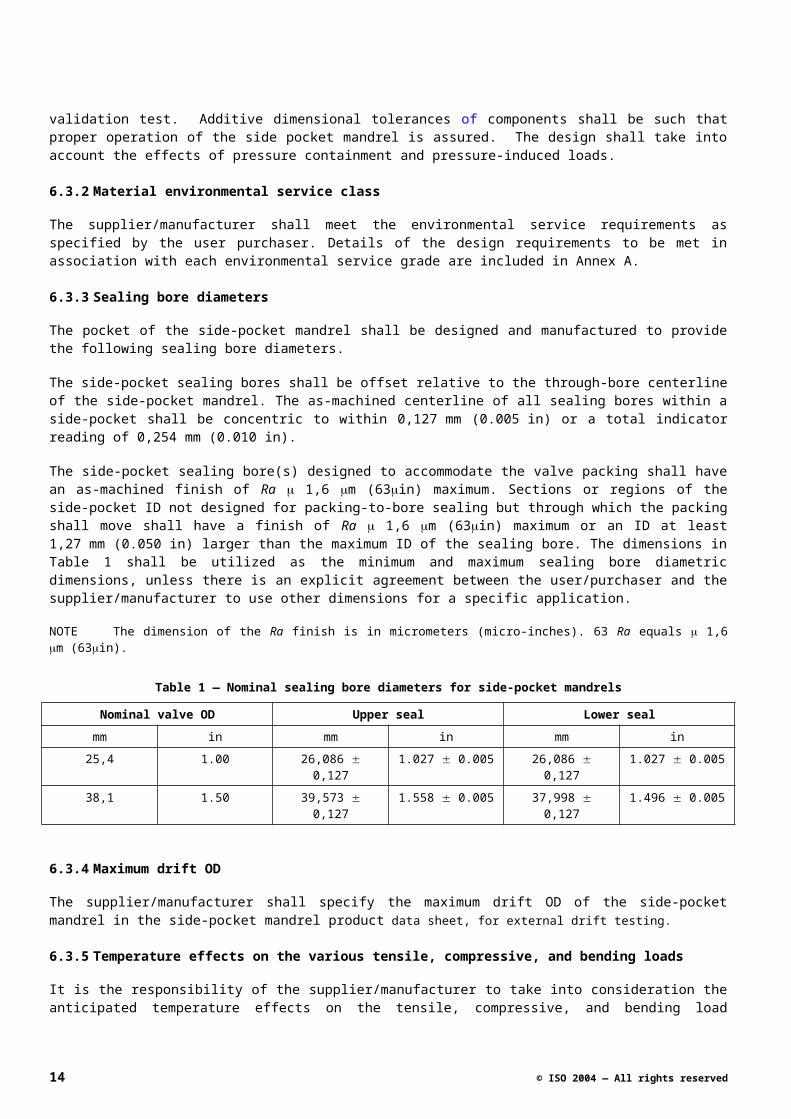
6.3.3 Sealing bore diameters
The pocket of the side-pocket mandrel shall be designed and manufactured to provide the following sealing bore diameters.
The side-pocket sealing bores shall be offset relative to the through-bore centerline of the side-pocket mandrel. The as-machined centerline of all sealing bores within a side-pocket shall be concentric to within 0,127 mm (0.005 in) or a total indicator reading of 0,254 mm (0.010 in).
The side-pocket sealing bore(s) designed to accommodate the valve packing shall have an as-machined finish of Ra 1,6 m (63in) maximum. Sections or regions of the side-pocket ID not designed for packing-to-bore sealing but through which the packing shall move shall have a finish of Ra 1,6 m (63in) maximum or an ID at least 1,27 mm (0.050 in) larger than the maximum ID of the sealing bore. The dimensions in Table 1 shall be utilized as the minimum and maximum sealing bore diametric dimensions, unless there is an explicit agreement between the user/purchaser and the supplier/manufacturer to use other dimensions for a specific application.
NOTE The dimension of the Ra finish is in micrometers (micro-inches). 63 Ra equals 1,6 m (63in).
Table 1 — Nominal sealing bore diameters for side-pocket mandrels
Nominal valve OD Upper seal Lower seal
mm in mm in mm in
25,4 1.00 26,086 0,127 1.027 0.005 26,086 0,127 1.027 0.005
38,1 1.50 39,573 0,127 1.558 0.005 37,998 0,127 1.496 0.005
© ISO 2004 — All rights reserved 11
6.3.4 Maximum drift OD
The supplier/manufacturer shall specify the maximum drift OD of the side-pocket mandrel in the side-pocket mandrel product data sheet, for external drift testing.
6.3.5 Temperature effects on the various tensile, compressive, and bending loads
It is the responsibility of the supplier/manufacturer to take into consideration the anticipated temperature effects on the tensile, compressive, and bending load capabilities. The combined load and pressure ratings of the side-pocket mandrel may be affected. If this occurs, the supplier/manufacturer shall inform the user/purchaser.
6.3.6 Elastomers and non-metallics
Design of elastomeric and non-metallic components shall be in accordance with the supplier/manufacturer’s documented requirements.
6.3.7 Tensile and compressive loads
The tensile and compressive load carrying capacity of the side-pocket mandrel shall be specified and documented by the supplier/manufacturer. These values are for the side-pocket mandrel exclusive of end connections. They shall be based on the critical cross-section of the side-pocket mandrel.
6.3.8 Performance rating
The supplier/manufacturer shall state the pressure, temperature, and axial maximum tensile/compressive load conditions used to determine the performance ratings, as applicable for the products. This information may be provided in an operating performance envelope; an example is given in Annex G.
NOTE Compressive loading is not a relevant parameter in the performance rating under normal operating conditions. This information is typically not available on non-round shapes. It can be provided with specific testing.
6.3.9 Design methods
The supplier/manufacturer shall design the side-pocket mandrels using one or more of the following:
a) finite element analysis;
b) proprietary equations and/or methods;
c) standard equations;
d) experimental stress analyses;
e) proof test analysis.
This International Standard does not dictate the methods, equations, or procedures for design purposes.
All pressure-containing parts shall be designed to satisfy the manufacturer’s test pressures and to meet the conditions defined in the functional specification. The assumptions, calculations, and/or other design criterion shall be detailed in the design file for that product.
NOTE It is good design practice for all exterior protrusions to be well rounded and/or beveled to prevent handing difficulties as the side-pocket mandrels are lowered into or retrieved from the well. Good design practice is also for all interior surfaces to be free of sharp shoulders and crevices that have no design function but which may interfere with other tools that are passing through the side-pocket mandrel.
12 © ISO 2004 — All rights reserved
6.4 Design verification
Design verification shall be performed to ensure that each design meets the supplier’s/manufacturer’s technical specifications. Design verification includes activities such as design reviews, design calculations, physical tests, comparison with similar designs and historical records of defined operating conditions.
6.5 Allowable design changes
6.5.1 General
Side-pocket mandrels of the same design family may use the same documented design validation test results. A design family shall consist of side-pocket mandrel products that have configurations, materials, and applications that are sufficiently similar to utilize a common methodology for establishing their design performance. Design changes that affect the pressure or load bearing capacity of the side-pocket mandrel are not allowable design changes. Documentation of design changes shall be maintained in the product design file.
6.5.1.1 Design changes
Design changes to existing products within a design family that meet the following requirements shall not change their status as being part of the design family and shall not change their validation status by association within a qualified design family:
The design changes do not require a change in the common methodology for establishing design performance within the design family.
The operational parameters for the product(s) that are having a design change are consistent with the operational parameters for the design family.
A design that undergoes a substantive change as defined by the supplier/manufacturer becomes a new design requiring design validation and product functional testing. Justifications for design changes that are identified as non-substantive shall be documented.
For side-pocket mandrels with unique or multiple features that do not constitute a substantive change of the design, the new feature(s) shall be tested per the supplier/manufacturer’s documented requirements for design validation of that feature. Acceptance criteria and results shall be documented.
6.6 Design validation requirements
6.6.1 General
The supplier/manufacturer shall, as a minimum, use these design validation procedures to assure that each side-pocket mandrel design family fulfils the functional requirements.
6.6.2 Design validation
Design validation testing shall be performed on each size, type, and model of side-pocket mandrel to ensure that the side-pocket mandrel design meets the suppliers/manufacturer’s technical specifications. Design validation testing includes activities such as design reviews, design calculations, and comparison with similar designs and historical records of defined operating conditions.
6.6.3 Design validation grade
The design validation grade specifies the design validation process(es), procedure(s), and test(s) required for each design validation grade. See Annex B for a detailed description of each specific process, procedure, or test.
© ISO 2004 — All rights reserved 13
6.6.4 Optional design validation testing
Some applications may require additional design validation testing. These shall be specified by the user/purchaser in the functional specification.
6.7 Product functional testing requirements
6.7.1 General
The supplier/manufacturer shall use the following test(s) and/or process(es) to demonstrate that each side-pocket mandrel that is produced fully meets the design specifications.
6.7.2 Product functional testing grade
The process or procedure(s) that shall be followed for each product functional testing grade are included in Annex C.
6.7.3 Optional product functional testing
Some functional specifications may require additional product functional testing. These shall be defined by the user/purchaser in the functional specification, and contractually agreed to by the user/purchaser and supplier/manufacturer.
7 Supplier/manufacturer requirements
7.1 General
This clause contains the detailed requirements to verify that each product manufactured meets the functional specifications in clause 5 and the technical specifications in clause 6. As a minimum, each of the following topics shall be addressed by the supplier/manufacturer.
7.2 Documentation and data control
7.2.1 General
The supplier/manufacturer shall establish and maintain documented procedures to control all documents and data that relate to the requirements of this International Standard. The retained documents and data shall be maintained to demonstrate conformance to specified requirements. All documents and data shall be legible and shall be sorted and retained in such a way that they are readily retrievable in facilities that provide a suitable environment to prevent damage or deterioration and to prevent loss. Documents and data may be in the form of any type of media, such as hard copy or electronic media. All documents and data shall be available and auditable by the user/purchaser. All design validation, design verification and product functional testing documents and data, as listed below, shall be maintained for 5 years after date of last manufacture.
Functional and technical specifications.
Supplier/manufacturer’s quality manual.
Required grade of QC (quality control) documentation as specified in 5.9.
One complete set of drawings, written specifications, design calculations, and design standards.
Instructions providing methods for the safe installation and use of the side-pocket mandrel. This document shall state the operations that are permitted and shall preclude those operations that may lead to failure and/or non-compliance with the functional and performance requirements.
14 © ISO 2004 — All rights reserved
Material type, yield strength, and connection identification for the actual end connection(s) provided with the side-pocket mandrel (where applicable).
Welding procedure specification (WPS).
Weld procedure qualification record (PQR).
Welder/welding operator performance qualification (WPQ).
7.2.2 User/purchaser documentation
A product data sheet (see Annex F) for each line item on each order shall be supplied upon delivery of the order to the user/purchaser, as required.
NOTE The intent of this is to require a separate product data sheet for each unique product or set of products that are part of a specific design family.
It shall contain at least the following, where applicable.
Name and address of supplier/manufacturer.
Manufacturer assembly part number.
Manufacturer product name.
Product type.
Product characteristic.
Metallic materials.
Non-metallic materials.
Drift diameters.
Overall length.
Temperature range for rated pressure.
Rated pressure.
Top/bottom connection(s).
Conveyance method.
Maximum conveyance OD, inclusive of running equipment, as applicable.
Retrieval method (if retrievable).
Quality control grade.
Design validation grade.
Technical/operations manual identification.
Product functional testing grade
Environmental service grade
© ISO 2004 — All rights reserved 15
7.2.3 Technical/operations manual
A technical/operations manual shall be available for products supplied in accordance with this International Standard and shall contain at least the following information.
Manual reference number and revision level.
Product data sheet, as shown in Annex F.
Operational procedures.
Pre-installation inspection procedures.
Storage recommendations.
Representative drawing showing major dimensions (OD’s, ID’s and lengths).
Special precautions and handling.
7.2.4 Design documentation
It is recommended that documentation of designs include methods, assumptions, calculations and design requirements. Design requirements include but are not be limited to those criteria for size, test pressures, materials, environment (temperature limits, service class, chemicals) and other pertinent requirements upon which the design is based. Design documentation may be reviewed and verified by a qualified individual other than the individual who created the original design.
7.3 Product identification requirements
7.3.1 General
The supplier/manufacturer shall clearly identify and mark each side-pocket mandrel according to the requirements in 7.3.2 and 7.3.3.
7.3.2 Product identification
Each product furnished to this International Standard shall be permanently identified using low stress marking devices, which include interrupted dot or rounded cold, die stamp, or vibratory methods. Supplier/manufacturer specifications shall define the method(s) and location of the markings. The following information, as a minimum, shall be marked on each side-pocket mandrel:
supplier/manufacturer's name or mark;
date (month and year) of manufacture;
supplier/manufacturer's part number and unique traceable serial number.
Painted marking requirements shall include an arrow pointing up and word "UP" adjacent to the arrow in capital letters on the flat of oval side-pocket mandrels and the round of round side-pocket mandrels toward the upper swage.
NOTE If the manufacturer's part number does not include thread type, size, and mass, then this information should be added as additional information.
7.3.3 Traceability
All components, weldments, sub-assemblies, and assemblies of equipment supplied in accordance with this International Standard shall be traceable to a job lot, for which components and weldments shall also identify the
16 © ISO 2004 — All rights reserved
heat(s) or batch lot(s) included. All components and weldments in a multi-heat or batch job lot shall be rejected if any heat or batch does not comply with specified requirements. Individual component identification shall be maintained to facilitate traceability until the manufacturer’s final inspection is completed.
Traceability for side pocket mandrels is considered sufficient if the equipment and documentation meets the requirements of this International Standard when it leaves the manufacturer's inventory.
7.4 Quality control requirements
7.4.1 General
This International Standard provides for three quality control grades. Requirements for each of these grades are specified in 7.4.4.
7.4.2 Quality control personnel qualifications
All personnel performing quality control activities directly affecting material and product quality shall be qualified in accordance with the supplier/manufacturer's documented requirements.
7.4.3 Manufacturing non-conformance
The supplier/manufacturer shall establish and maintain documented procedures to ensure that an assembly or component that does not conform to specified requirements is prevented from unintended use or installation. This control shall provide for identification, documentation, evaluation, segregation (when applicable), and disposition of non-conforming assemblies or components.
The responsibility for review and authority for the disposition of non-conforming assemblies or components shall be defined by the supplier/manufacturer. Non-conforming assemblies or components may be:
reworked to meet the specified requirements;
accepted without repair by concession of supplier/manufacturer's authorized personnel, provided the violated manufacturing criterion is categorized as unnecessary to satisfy the design acceptance criteria;
rejected or scrapped.
Repaired and/or reworked assemblies or components shall be inspected in accordance with the appropriate quality control grade.
7.4.4 Quality control grade selection
This International Standard provides 3 grades of quality control for side-pocket mandrel products, as shown in Table D.1. The user/purchaser shall specify, in the functional specification, the grade of quality control and/or additional requirements when desired.
Q3 Certification of conformance, on request of user/purchaser
Q2 Certificate of conformance, plus additional NDE and mill certification for manufacturer-specified critical (for example: pressure-containing/pressure-retaining) components, on request of user/purchaser.
Q1 Certification of conformance, plus additional NDE and mill certification on all components, except common hardware items, on request of user/purchaser.
As a minimum products shall be supplied to Q3 unless the user/purchaser specifies grade Q2 or Q1.
NOTE The user/purchaser may also specify an additional quality/certification system to apply to equipment supplied to this International Standard. See Annex D for a detailed description of each specific process, procedure, or test.
© ISO 2004 — All rights reserved 17
7.4.5 Calibration
Calibration of measuring equipment used for product design validation testing and product functional testing shall be identified, controlled, calibrated, and adjusted in accordance with an internationally or nationally recognized standard(s) that is/are no less stringent than the requirements included herein.
Time intervals for calibrating test measurement devices shall be established based on repeatability and degree of usage. Calibration intervals shall be a maximum of three months until recorded calibration history can be established. Intervals may be lengthened or shortened based on calibration history. The calibration interval cannot be increased by more than twice the previous interval.
Pressure measuring devices used for product design validation testing shall be calibrated with a nationally certified master pressure measuring device or a dead-weight tester. Pressure measuring systems shall be calibrated to a maximum variation of 0,25 % full-scale accuracy. Pressure transducers, digital readouts, and gauges shall be readable to 0,1 % of full-scale range. Pressure transducer systems shall be used for acceptance only within their calibrated range. Temperature measurement devices shall be calibrated to a maximum variation of 2,0 °C (3.8 °F).
Pressure measuring devices used for product functional testing shall be calibrated with a nationally certified master pressure measuring device or a dead-weight tester. Pressure measuring systems shall be calibrated to a maximum variation of 1,0 % full-scale accuracy. Pressure transducers, digital readouts, and gauges shall be readable to 0,5 % of full-scale range. Pressure transducer systems shall be used for acceptance only within their calibrated range.
Pressure measurements shall be taken at not less than 25 % nor more than 75 % of the full span of the pressure gauge. Pressure gauges shall be calibrated at 25 % 2,5 %, 50 % 2,5 %, and 75 % 2,5 % of scale and pressure transducer systems shall be calibrated over their intended range of use as specified in supplier/manufacturer’s documents.
Measuring/testing equipment calibration
7.6.6.1 Measuring and testing equipment used for acceptance shall be identified, inspected, calibrated and adjusted at specific intervals in accordance with documented specifications, ANSI/NCSL Z540-1, and this International Standard.
7.6.6.2 Pressure measuring devices shall:
a) be readable to at least 0,5 % of full scale range or less as required to perform the specified measurement;
b) be calibrated to maintain 2 % accuracy of full scale range.
7.6.6.3 Pressure measuring devices shall be used only within the calibrated range
7.6.6.4 Pressure measuring devices shall be calibrated with a master pressure measuring device or a dead weight tester. Calibration intervals for pressure-measuring devices shall be a maximum of three months until documented calibration history can be established. Calibration intervals shall then be established based on repeatability, degree of usage and documented calibration history.
7.4.6 Material certifications
Supplier/manufacturer's mill test certificate of original material or supplier/manufacturer’s certification of test results are acceptable if the certifications include test results for mechanical properties and chemical composition for that heat of material. If the material is altered by subsequent processes that change its properties, then acceptance shall be based on either hardness or mechanical properties in accordance with ASTM A370 from the heat of material in question. These tests shall be completed using the heat treat cycle for which the material is to be qualified. If the initial test specimen fails, then two additional tests shall be successfully performed in order to qualify
18 © ISO 2004 — All rights reserved
the material. The material shall be rejected if the results of either of two additional tests do not meet specified requirements. If hardness is used for final acceptance, then hardness-strength correlations shall be documented by the supplier/manufacturer for that type of material.
Yield strength in this International Standard is defined as the 0,2 % yield offset strength in accordance with ASTM A370.
Acceptance of all materials, as defined above, shall be indicated either on the materials or in the records traceable to the materials.
Raw material used in the manufacture of components shall meet the following requirements:
certificate of conformance stating that the raw material meets the supplier/manufacturer’s documented specifications;
material test report so that the manufacturer can verify that the raw material meets the supplier/manufacturer’s documented specifications;
mechanical and physical properties (as applicable):
metallic materials: mechanical property test procedures and practices shall be in accordance with ASTM A370 for the metallic materials used for traceable components.
elastomers and non-metallics: mechanical property test procedures for elastomeric and non-metallic compound types shall be in accordance with the supplier/manufacturer’s documented requirements.
7.5 Heat treatment requirements
The following details the heat treatment requirements.
a) Heat treating of production parts shall be performed with heat-treating equipment that has been calibrated and surveyed.
b) Each furnace shall be surveyed within one year prior to heat-treating operations. When a furnace is repaired or rebuilt, a new survey shall be required before heat-treating.
c) Batch type and continuous type heat treating furnaces shall be calibrated in accordance with one of the following procedures:
1) Procedures specified in Section 5 of SAE-AMS-H-6875.
2) Procedures specified in Section 7 of BS 2M54.
3) Supplier/manufacturer's written specifications including acceptance criteria that are not less stringent than the procedures identified above.
7.6 Welding requirements
7.6.1 General
The supplier/manufacturer's welding control system shall include requirements for monitoring, updating, and controlling the qualifications of welders/welding operators and the use of welding procedure specifications. Instruments utilized to verify temperature, voltage, and amperage shall be serviced and calibrated in accordance with the side-pocket mandrel supplier/manufacturer’s written procedures.
All welding procedures, welders and welding operators shall be qualified in accordance with ASME Boiler and Pressure Vessel Code Section IX. Base metals that are not classified under the ASME P-number grouping shall be qualified as unassigned metals in accordance with QW-424.1, ASME Boiler and Pressure Vessel Code Section IX.
© ISO 2004 — All rights reserved 19
7.6.2 Welding consumables
Welding consumables shall conform to AWS or supplier/manufacturer’s written specifications. The supplier/manufacturer shall have a written procedure for selection, storage, and control of welding consumables. Materials of low hydrogen type shall be stored and used as recommended by the consumable manufacturer to retain their original low hydrogen properties.
7.6.3 Welding procedures/qualification records
7.6.3.1 General
Welding shall be performed in accordance with welding procedure specifications written and qualified in accordance with Article II of ASME Boiler and Pressure Vessel Code Section IX. The WPS shall describe all the essential and nonessential variables as defined in ASME Boiler and Pressure Vessel Code Section IX. The procedure qualification record shall record all essential variables as defined in ASME Boiler and Pressure Vessel Code Section IX of the weld procedure used for the qualification test(s).
7.6.3.2 Hardness testing
The test weldment for hardness testing shall have the same type of post-weld heat treatment as the final product. For side-pocket mandrel environmental service grade E2, hardness tests across the weld, base material and heat-affected zone (HAZ) cross-section shall be performed in accordance with ASTM E18 and recorded as part of the PQR. Maximum hardness values for environmental class E2 service shall not exceed NACE MR-01-75 requirements.
7.6.4 Welder/welding operator performance qualification
Welders and welding operators shall be qualified in accordance with Article III of ASME Boiler and Pressure Vessel Code Section IX. Records of welding performance qualifications (WPQ) test shall include all welding parameters as detailed in ASME Section IX.
7.7 Non-destructive examination (NDE) requirements
7.7.1 General
The supplier/manufacturer’s qualified representative shall inspect all accessible surfaces for cracks and damage, ensuring that the technical specification is met.
NDE shall be performed and accepted according to the supplier/manufacturer’s written specification that shall include the requirements defined in 7.7. The size of the sample of components to be tested shall be in compliance with the appropriate quality control grade level as indicated in Table D.1. All welds and adjacent heat-affected zones of the specified sample lot shall be non-destructively examined by one or more of the following methods: radiography, magnetic particle, ultrasonic, or liquid penetrant as designated in the supplier/manufacturer's specification.
If the examination produces an unacceptable indication, 20% of the side-pocket mandrels from the job lot shall be examined. If another indication is found to be unacceptable, then 100% of the job lot shall be examined. Any unacceptable indications shall be removed, repaired, and re-examined using the original NDE method. A “report of non-conformance” shall be generated for non-conforming items. The disposition of all non-conforming items shall be documented.
7.7.2 NDE personnel qualification
Non-destructive examination personnel shall be qualified in accordance with requirements specified in ASNT RP SNT-TC-1A, Level II, or supplier/manufacturer’s requirements that are not less stringent.
20 © ISO 2004 — All rights reserved
7.7.3 NDE personnel qualification records
Records that document the qualifications of NDE testing personnel shall be maintained by the supplier/manufacturer.
7.7.4 Visual examination personnel qualifications
Personnel performing visual examinations shall have an annual eye examination in accordance with ASNT RP SNT-TC-1A, as applicable to the discipline to be performed. Visual examination personnel qualifications shall be in accordance with the supplier/manufacturer's written requirements.
7.7.5 Hardness examinations
Hardness testing shall be performed in accordance with procedures specified in ASTM E10 (Brinell) or ASTM E18 (Rockwell). The hardness acceptance criteria shall be in accordance with the supplier/manufacturer’s specifications. All hardness conversions shall be in accordance with ASTM E140 or in accordance with documented test results performed on a particular material.
7.7.6 Radiographic examinations
Radiographic testing shall meet the requirements of ASTM E94. The acceptance criteria shall be in accordance with ASME Boiler and Pressure Vessel Code, Section VIII, Division I, UW-5l.
7.7.7 Ultrasonic examinations
Ultrasonic testing shall be in accordance with ASME Boiler and Pressure Vessel Code Section V, Article 5. The acceptance criteria shall be in accordance with ASME Boiler and Pressure Code Section VIII, Division 1, Appendix 12.
7.7.8 Magnetic particle examinations
Magnetic particle examinations shall be in accordance with the requirements of ASTM E709. The acceptance criteria are:
no relevant indication with a major dimension equal to or greater than 5 mm (3/16 in);
no more than ten relevant indications in any continuous 40 cm2 (6 in2) area;
four or more relevant indications in a line separated by less than 1,6 mm (1/16 in) (edge to edge) are unacceptable;
no relevant linear indications
no rounded indications greater than 3 mm (1/8 in) for welds whose depth is 16 mm (5/8 in) or less; or 5 mm (3/16 in) for welds whose depth is greater than 16 mm (5/8 in).
7.7.9 Liquid penetrant examination
Liquid penetrant examination shall be in accordance with the requirements of ASTM E165. These acceptance criteria are:
no relevant linear indications;
no relevant rounded indication with a major dimension equal to or greater than 5 mm (3/16 in);
four or more relevant rounded indications in a line separated by less than 1,6 mm (1/16 in) (edge to edge) are unacceptable;
© ISO 2004 — All rights reserved 21
no rounded indications greater than 3 mm (1/8 in) for welds whose depths are 16 mm (5/8 in) or less; or 5 mm (3/16 in) for welds whose depth is greater than 16 mm (5/8 in).
7.7.10 Component dimensional examination
Components and assemblies shall be dimensionally inspected to assure proper function and compliance with design criteria and technical specifications. The frequency of these examinations shall be performed as detailed in the supplier/manufacturer's written requirements.
7.7.11 NDE evaluations
When defined in the functional and/or the technical specification, NDE testing shall be performed as specified herein.
Each side-pocket mandrel shall have hardness tests performed per the supplier/manufacturer's written procedure. The test results shall meet acceptance criteria as detailed in clause 7.7.5. The results of each evaluation shall be documented.
7.8 Storage and shipping preparation
7.8.1 General
The supplier/manufacturer shall comply with the following requirements for storage and shipping of side-pocket mandrel products.
7.8.2 Draining, cleaning, and/or drying
The processes for draining, cleaning, and/or drying of side-pocket mandrel products, after they have been tested, shall be specified in the supplier/manufacturer's written procedures. The minimum standard shall be that the products shall be free of any foreign matter and/or liquids.
7.8.3 Threaded connections and packing bores
All threaded connections and packing bores shall be protected as specified in the supplier/manufacturer's written procedures. Protection of the threaded connections shall meet ISO 11960, or for a non-ISO thread, the thread supplier/manufacturer’s written requirements. The minimum standard for the protection of the packing bores shall be coating of the packing bores with a rust inhibitor per the supplier/manufacturer's written procedures.
7.8.4 Painting of side-pocket mandrels
Painting of side-pocket mandrels shall be done in accordance with the supplier/manufacturer’s written procedures and the procedure shall include details of the required protection of all threads and side-pocket packing bores and seals from paint spray. As a minimum standard, no paint is allowed in the packing bores or on the threaded surfaces.
7.8.5 Permanent marking prior to coating
Prior to coating, all permanent marking that is required by International Standard 17078.1 shall be completed. No coating is allowed on or in active threads or in the side-pocket packing bore other than coating, plating, or other surface treatments that are specified by the supplier/manufacturer for these surfaces.
7.9 Repair
Repair activities to side-pocket mandrels shall return the product to a condition meeting all requirements stated in this International Standard or the edition in effect at the time of original manufacture.
22 © ISO 2004 — All rights reserved
Annex A (normative)
Environmental service requirements
A.1 Purpose
A.1.1 General
The purpose of this normative annex is to provide detailed requirements for each of the four environmental service classes that are specified in this International Standard. The supplier/manufacturer shall establish criteria and select materials to meet the requirements of the following environmental service classifications, or use materials agreed by the user/purchaser.
Table 1 — Environmental service classes
Environmental service classes Characteristics
E1 – Standard service (see A.1.2) Non-sour service
E2 – Sulfide stress cracking service (see A.1.3) H2S (sour) servicea
E3 – CO2 service (see A.1.4) CO2 serviceb
E4 – Special service (see A.1.5) Special service requirements defined by the user/purchaser
a In accordance with NACE MR-01-75.
b There are no published international standards for CO2 service. Each individual application shall be evaluated on a case-by-case basis.
A.1.2 Class E1: Standard service
Service in fluids that have an H2S partial pressure less than those listed for "sulfide stress cracking" in NACE MR-01-75 and no CO2 content. The standard material used for this service is 4130/4140 low-alloy steel (HRC 26 – 36). Other materials may be acceptable for this service if approved by the user/purchaser.
A.1.3 Class E2: Sulfide stress cracking or H2S (sour) service
Service in fluids that have an H2S partial pressure greater than those listed for "sulfide stress cracking" in NACE MR-01-75 and no CO2 content. Materials used for this service shall be compatible with NACE standards. Any welding processes used for this service shall meet NACE requirements.
A.1.4 Class E3: CO2 service
Service in fluids that have an H2S partial pressure less than those listed for "sulfide stress cracking" in NACE MR-01-75 but do have CO2 present. Examples of acceptable materials for this service, in order of resistance to CO2
corrosion, are: 9 Chrome, 410 Stainless Steel, 420 Stainless Steel, 13 Chrome, Super 13 Chrome, 22 Chrome, and Custom 450 Stainless Steel. Other materials may be acceptable for this service if approved by the user/purchaser.
© ISO 2004 — All rights reserved 23
A.1.5 Class E4: Special service (to be defined by user/purchaser)
This class may be used by the user/purchaser to specify "special" service requirements that are not otherwise covered in this International Standard. An example of this type of service might be a combination of both H 2S and CO2.
24 © ISO 2004 — All rights reserved
Annex B (normative)
Design validation requirements
B.1 Purpose
B.1.1 General
Each design validation grade requires a number of individual validation procedure(s), process(s), and test(s). The results shall be maintained in a design validation file that shall be legible and retrievable. The file shall contain test results that validate the design and shall be reviewed and approved by a qualified person other than the originator. This review shall confirm that, as a minimum, all of the design validation requirements of this International Standard have been met.
The specific procedures to be followed for each validation procedure, process, and test shall be documented by the supplier/manufacturer. For all pressure tests, all test pressures and associated temperatures are to be recorded on a continuous, time-based data collection file (system) and these test pressure and temperature readings are to be maintained in the validation test file. Pressure measurements shall be accurate to within 1.0% of the full scale of the pressure measurement device. Products qualified to a higher grade of design validation may be considered as qualified to any of the lower grades of design validation.
Three design validation grades are shown in Table B.1.
Table 1 — Design validation grades
V3 V2 V1
Documentation Historical record (see B.1.2.2) Required (see B.1.3.2) Required (see B.1.4.2)
Design review (burst, collapse, tolerance)
Required (see B.1.2.3) Required (see B.1.3.3) Required (see B.1.4.3)
Burst and collapse validation pressure test to destruction at ambient temperature
Not required (see B.1.2.4) Burst and collapse pressure test (see B.1.3.4)
Burst and collapse FEA (see B.1.4.7)
Pressure testing at rated temperature
Required (see B.1.2.5) Required (see B.1.3.5) Required (see B.1.4.5)
Internal pressure cycles Not required (see B.1.2.6) 10 cycles (see B.1.3.6) 10 cycles (see B.1.4.6)
Finite element analysis/strain gauge Not required (see B.1.2.7) Not required (see B.1.3.7) Burst and collapse (see B.1.4.7)
Flow control – Install/pull with kick-over tool
At 12 o'clock (see B.1.2.8) At 12 o'clock, 3 o'clock and 6 o'clock (see B.1.3.8)
At 12 o'clock, 3 o'clock and 6 o'clock (see
B.1.4.8)
Slick line operational test with kick-over tool
Not required (see B.1.2.9) Not required (see B.1.3.9) Required (see B.1.4.9)
Product validation internal drift tests Required (see C.1.2.4) Required (see C.1.3.4) Required (see C.1.4.4)
Product validation external drift test Required (see C.1.2.5) Required (see C.1.3.5) Required (see C.1.4.5)
© ISO 2004 — All rights reserved 25
B.1.2 Grade V3: Basic level or grade of side-pocket mandrel design validation/
B.1.2.1 General
Grade V3 design validation tests shall be conducted in the order shown. One or more sample test side-pocket mandrel(s) selected for this test shall pass each of these tests. In addition, any one or more samples selected for this test shall pass the following product functional testing grade F3 tests: internal pressure test, external pressure test, internal diameter drift test, and outside diameter drift test. These product functional tests shall be conducted, in the order listed, after all of the design validation/ tests have been completed.
B.1.2.2 Documentation
The supplier/manufacturer shall demonstrate, by use of documented historical records, that the subject side-pocket mandrel product has been on the market for a minimum of two years, that a minimum of 200 mandrels of the subject product have been sold to end users, and that a minimum of 100 mandrels have been placed in service by end users.
B.1.2.3 Design review (burst, collapse, tolerance)
The supplier/manufacturer shall have conducted a design review on this side-pocket mandrel product. The design review document shall include a review of the burst, collapse, and tensile strength characteristics of the design, and the tolerance accumulations of the design to insure that it meets the technical specifications.
B.1.2.4 Burst and collapse pressure test to destruction at ambient temperature
Not required for validation grade V3.
B.1.2.5 Pressure testing at maximum rated temperature
This is a hydrostatic or liquid media internal pressure test. The test shall be conducted at or above the rated pressure and maximum rated temperature. The tested mandrel shall hold the test pressure for a minimum of 5 min. The test pressure shall remain stable within 2 %.
B.1.2.6 Internal pressure cycles
Not required for validation grade V3.
B.1.2.7 Finite element analysis/strain gauge
Not required for validation grade V3.
B.1.2.8 Flow control – install/pull
This test is conducted with the side-pocket mandrel installed in a horizontal position, in a vise, with the pocket located at the top of the mandrel or in the “12 o’clock” position. A dummy flow control device with an appropriate latching mechanism shall be inserted into the mandrel pocket, latched in the pocket, and retrieved from the pocket, using the supplier/manufacturer’s procedures and acceptance criteria. This test shall be conducted using each of the latches, running tools, pulling tools, and kick-over tools that are claimed to be compatible with this side-pocket mandrel. The tool string shall consist of a knuckle joint directly connected to the kick-over tool with appropriate weight bars and jars. The side-pocket mandrel shall have a pup joint of a 1,22 m (4 ft) minimum length attached to the upper mandrel connection.
Side-pocket mandrels that do not have an orienting profile shall be tested at a minimum 15-degree angle from vertical inclination.
26 © ISO 2004 — All rights reserved
B.1.2.9 Slick line operational test with kick-over tool
Not required for validation/ grade V3.
B.1.3 Grade V2: Intermediate level or grade of side-pocket mandrel design validation/
B.1.3.1 General
Grade V2 design validation tests shall be conducted in the order shown. One or more sample test side-pocket mandrel(s) selected for this test shall pass each of these tests, with the exception that only one test specimen shall be burst pressure tested to failure, and only one shall be collapse pressure tested to failure. In addition, any one or more samples selected for this test, except for those that are failed in the burst and collapse pressure tests, shall pass the following product functional testing grade F3 tests: internal pressure test, external pressure test, internal diameter drift test, and outside diameter drift test. These product functional tests shall be conducted, in the order listed, after all of the design validation tests have been completed.
B.1.3.2 Documentation
The design file shall include all of the design validation/verification assumptions, calculations, model evaluations, test results, and any other supporting documentation that has been used to verify the design.
B.1.3.3 Design review (burst, collapse, tolerance)
The supplier/manufacturer shall have conducted a design review on this side-pocket mandrel product. The design review document shall include a review of the burst, collapse, and tensile strength characteristics of the design, and the tolerance accumulations of the design to insure that it meets the technical specifications.
B.1.3.4 Burst and collapse pressure test to destruction at ambient temperature
B.1.3.4.1 Burst
A minimum of one unit of this design shall be internally pressure tested to failure. This shall be a hydro test at ambient temperature. When conducting this test, the pressures where permanent deformation occurs and where failure occurs shall be recorded.
B.1.3.4.2 Collapse
A minimum of one unit of this design shall be externally pressure tested to failure. This shall be a hydro test at ambient temperature. When conducting this test, the pressures where permanent deformation occurs and where failure occurs shall be recorded.
B.1.3.5 Pressure testing at maximum rated temperature
This is a hydrostatic or liquid media internal pressure test. The test shall be conducted at or above the rated pressure and maximum rated temperature. The tested mandrel shall hold the test pressure for a minimum of 5 min. The test pressure shall remain stable within 2 %.
B.1.3.6 Internal pressure cycles
This is an internal hydrostatic test. The internal pressure shall be raised to the rated pressure, at ambient temperature, held at this value for a minimum of 2 min, with a maximum of 2 % pressure reduction and with no perceptible leaks, and bled to atmospheric. This cycle shall be repeated a minimum of 10 times. On the last cycle, the pressure shall be held for a minimum of 5 min, after the test side-pocket mandrel has been isolated from the pressure source.
© ISO 2004 — All rights reserved 27
B.1.3.7 Finite element analysis/strain gauge
Not required for validation grade V2.
B.1.3.8 Flow control – Install/pull
This test shall be conducted with the side-pocket mandrel installed in a horizontal position, in a vise, with the pocket located at the top, side, and bottom of the mandrel or in the “12 o’clock, 3 o’clock, and 6 o’clock” positions. In each orientation, a dummy flow control device with an appropriate latching mechanism shall be inserted into the mandrel pocket, latched in the pocket, and retrieved from the pocket, using the supplier/manufacturer’s procedures and acceptance criteria. This test shall be conducted using each of the latches, running tools, pulling tools, and kick-over tools that are claimed to be compatible with this side-pocket mandrel. The tool string shall consist of a knuckle joint directly connected to the kick-over tool with appropriate weight bars and jars. The side-pocket mandrel shall have a pup joint of a 1,22 m (4 ft) minimum length attached to the upper mandrel connection.
Side-pocket mandrels that do not have an orienting profile shall be tested at a minimum 15-degree angle from vertical inclination.
B.1.3.9 Slick line operational test with kick-over tool
Not required for validation grade V2.
B.1.4 Grade V1: Highest level or grade of side-pocket mandrel design validation/
B.1.4.1 General
Grade V1 design validation tests shall be conducted in the order shown. One or more sample test side-pocket mandrel(s) selected for this test shall pass each of these tests. In addition, any one or more samples selected for this test shall pass the following product functional testing grade F3 tests: internal pressure test, external pressure test, internal diameter drift test, and outside diameter drift test. These product functional tests shall be conducted, in the order listed, after all of the design validation tests have been completed.
B.1.4.2 Documentation
The design file shall include all of the design validation assumptions, calculations, model evaluations, test results, and any other supporting documentation that has been used to verify the design.
B.1.4.3 Design review (burst, collapse, tolerance)
The supplier/manufacturer shall have conducted a design review on this side-pocket mandrel product. The design review document shall include a review of the burst, collapse, and tensile strength characteristics of the design, and the tolerance accumulations of the design to insure that it meets the technical specifications.
B.1.4.4 Burst and collapse pressure test to destruction at ambient temperature
Not required for validation grade V1.
B.1.4.5 Pressure testing at maximum rated temperature
This is a hydrostatic or liquid media internal pressure test. The test shall be conducted at or above the rated pressure and maximum rated temperature. The tested mandrel shall hold the test pressure for a minimum of 5 min. The test pressure shall remain stable within 2 %.
B.1.4.6 Internal pressure cycles
This is an internal hydrostatic test. The internal pressure shall be raised to the rated pressure, at ambient temperature, held at this value for a minimum of 2 min, with a maximum 2 % leakage, and bled to atmospheric.
28 © ISO 2004 — All rights reserved
This cycle shall be repeated a minimum of 10 times. On the last cycle, the pressure shall be held for a minimum of 5 min, after the test side-pocket mandrel has been isolated from the pressure source.
B.1.4.7 Finite element analysis/strain gauge
B.1.4.7.1 Finite element analysis (FEA)
A finite element analysis shall be conducted to define, as a minimum, the rated pressure of the side-pocket mandrel under internal pressure, external pressure, and tensile loading conditions. All assumptions and conclusions shall be documented as part of the analysis.
B.1.4.7.2 Strain gauge
Strain gauges, mounted both circumferentially and longitudinally on the side-pocket mandrel, shall be used to verify the finite element analysis. To be acceptable, the measured strains shall be within 5 % of the values calculated by the FEA.
B.1.4.7.3 Flow control – install/pull
This test shall be conducted with the side-pocket mandrel installed in a horizontal position, in a vise, with the pocket located at the top, side, and bottom of the mandrel or in the “12 o’clock, 3 o’clock, and 6 o’clock” positions. In each orientation, a dummy flow control device with an appropriate latching mechanism shall be inserted into the mandrel pocket, latched in the pocket, and retrieved from the pocket, using the supplier/manufacturer’s procedures and acceptance criteria. This test shall be conducted using each of the latches, running tools, pulling tools, and kick-over tools that are claimed to be compatible with this side-pocket mandrel. The tool string shall consist of a knuckle joint directly connected to the kick-over tool with appropriate weight bars and jars. The side-pocket mandrel shall have a pup joint of a 1,22 m (4 ft) minimum length attached to the upper mandrel connection.
B.1.4.8 Slick line operational test with kick-over tool
This test shall be conducted with the side-pocket mandrel installed in a 45° inclined position with the pocket located at the top, side, and bottom of the mandrel or in the “12 o’clock, 3 o’clock, and 6 o’clock” positions. A minimum 3,05 m (10 ft) pup joint shall be connected on the upper end of the mandrel and a minimum 1,83 m (6 ft) joint on the lower end. A lubricator stack shall be installed on the upper end of the top pup joint. In each orientation, a dummy flow control device with an appropriate latching mechanism shall be inserted into the mandrel pocket, latched in the pocket, and retrieved from the pocket using each of the kick-over tools that are claimed by the supplier/manufacturer to be compatible with this side-pocket mandrel, using the supplier/manufacturer’s procedures and acceptance criteria. The kick-over tools shall be run into and out of the mandrels using slick line.
A further requirement of this test shall be to insert each of the kick-over tools into the bottom of the mandrel body without pup joints or other threaded accessories to verify that the tool, when inserted into the mandrel, does not trip the kick-over tool or hang up in the mandrel body at any point below the orienting sleeve. This test shall be re-run with the mandrel in a fixed (12-o’clock) position and the kick-over tool oriented and held at 10° increments from the top (12-o’clock) position to the bottom (6-o’clock) position.
© ISO 2004 — All rights reserved 29
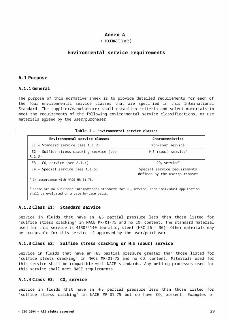
Annex C (normative)
Product functional testing requirements
C.1Purpose
C.1.1 General
Each product functional testing grade requires a number of individual functional testing procedure(s), process(s), or test(s). The results of all of these shall be maintained in manufacturing or quality control files.
The specific procedures to be followed for each functional test shall be documented by the supplier/manufacturer. For all pressure tests, test pressures are to be recorded on a continuous, time-based data collection file (system) and these pressure and temperature test readings are to be maintained. Pressure measurements shall be accurate to within 1,0 % of the full scale of the pressure measurement device.
Table 1 — Product functional testing grades
F3 F2 F1
Internal pressure test 100 % (see C.1.2.2) 100 % (see C.1.3.2) 100 % (see C.1.4.2)
External pressure test 0 % (see C.1.2.3) 5 % (see C.1.3.3) 100 % (see C.1.4.3)
Internal diameter drift test 100 % (see C.1.2.4) 100 % (see C.1.3.4) 100 % (see C.1.4.4)
External diameter drift test 100 % (see C.1.2.5) 100 % (see C.1.3.5) 100 % (see C.1.4.5)
Installation/removal method – Kick-over tool
0 % (see C.1.2.6) 5 % (see C.1.3.6) 100 % (see C.1.4.6)
C.1.2 Grade F3: Basic level or grade of side-pocket mandrel product functional testing
C.1.2.1 General
The product functional tests for grade F3 listed in C.1.2.2 through C.1.2.6 shall be conducted in the order shown.
C.1.2.2 Internal pressure test
This is a hydro or liquid media internal pressure test. It shall be conducted on 100 % of the side-pocket mandrels in each job lot. It shall be conducted at or above the rated pressure and at ambient temperature. The tested mandrel shall hold the test pressure for a minimum of 5 min, after stabilization of the pressure. To be considered stabilized, the pressure shall remain "constant" with a variation of less than 2 % of the test pressure. There shall be no perceptible leaks in the mandrel body.
C.1.2.3 External pressure test
Not required for functional testing grade F3.
C.1.2.4 Internal diameter drift test
A standard, minimum length 106,68 cm (42 in) drift bar (as specified in ISO 11960) shall be passed unencumbered through the side-pocket mandrel with a flow control device and latch in place in the mandrel pocket. The outside
30 © ISO 2004 — All rights reserved
diameter of the drift bar shall be the drift internal diameter of the side-pocket mandrel being tested, with tolerance in accordance with ISO 11960. This shall be performed on 100 % of the mandrels in each job lot. The drift bar shall be maintained and verified as part of the supplier/manufacturer’s standard calibration program.
C.1.2.5 External diameter drift test
The side-pocket mandrel shall pass unencumbered through a section of casing or an equivalent tube or fixture that has an ID not greater than the drift OD of the side-pocket mandrel. This shall be performed on 100 % of the mandrels in each job lot. The minimum length of the piece of casing, tube, or fixture shall be at least as long as the side-pocket mandrel. The internal diameter of the test casing, tube section, or test fixture shall be maintained and verified as part of the supplier/manufacturer’s standard calibration program.
C.1.2.6 Installation/removal method – Kick-over tool
Not required for functional testing grade3.
C.1.3 Grade F2: Intermediate level or grade of side-pocket mandrel product functional testing
C.1.3.1 General
The product functional tests for grade F2 listed in C.1.3.2 through C.1.3.6 shall be conducted in the order shown.
C.1.3.2 Internal pressure test
This is a hydro or liquid media internal pressure test. It shall be conducted on 100 % of the side-pocket mandrels in each job lot. It shall be conducted at or above the rated pressure and at ambient temperature. The tested mandrel shall hold the test pressure for a minimum of 5 min, after stabilization of the pressure. To be considered stabilized, the pressure shall remain "constant" with a variation of less than 2 % of the test pressure. There shall be no perceptible leaks in the mandrel body.
C.1.3.3 External pressure test
This test is a hydro or liquid media external pressure test. It shall be conducted on 5% of each job lot or a minimum of one mandrel. It shall be conducted at or above the rated pressure and at ambient temperature. The tested mandrel shall hold the test pressure for a minimum of 5 min, after stabilization of the pressure. To be considered stabilized, the pressure shall remain "constant" with a variation of less than 2 % of the test pressure.
C.1.3.4 Internal diameter drift test
A standard, minimum length 106,68 cm (42 in) drift bar (as specified in ISO 11960) shall be passed unencumbered through the side-pocket mandrel with a flow control device and latch in place in the mandrel pocket. The outside diameter of the drift bar shall be the drift internal diameter of the side-pocket mandrel being tested, with tolerance in accordance with ISO 11960. This shall be performed on 100 % of the mandrels in each job lot. The drift bar shall be maintained and verified as part of the supplier/manufacturer’s standard calibration program.
C.1.3.5 External diameter drift test
The side-pocket mandrel shall pass unencumbered through a piece of casing or an equivalent tube or fixture that has an ID not greater than the drift OD of the side-pocket mandrel. This shall be performed on 100 % of the mandrels in each job lot. The minimum length of the piece of casing, tube, or fixture shall be at least as long as the side-pocket mandrel. The internal diameter of the test casing, tube section, or test fixture shall be maintained and verified as part of the supplier/manufacturer’s standard calibration program.
C.1.3.6 Installation/removal method – Kick-over tool
This test is conducted with the side-pocket mandrel installed in a horizontal position, in a vice, with the pocket located at the top of the mandrel or in the “12 o’clock” position. It shall be conducted on 5 % of each job lot or a
© ISO 2004 — All rights reserved 31
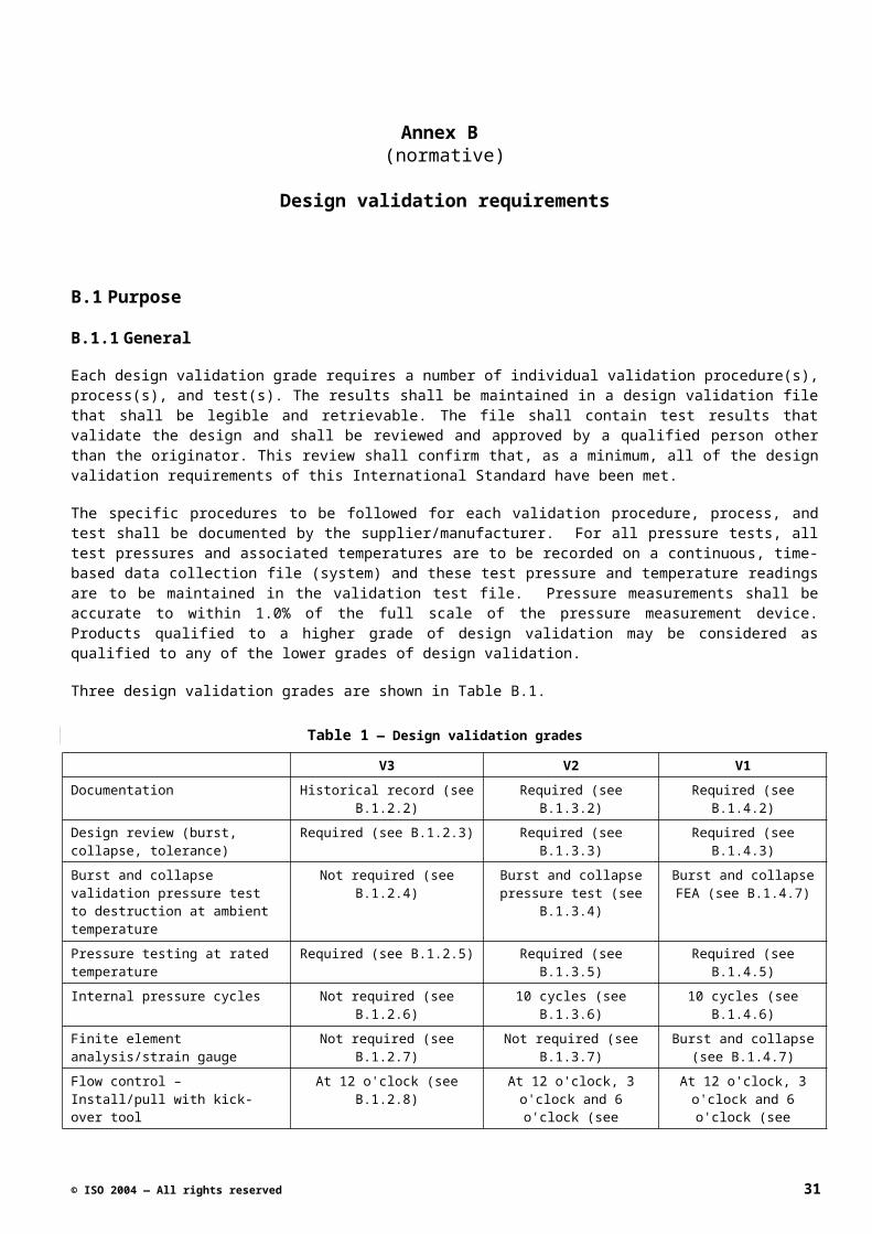
minimum of one mandrel. A flow control device with an appropriate latching mechanism shall be inserted into the mandrel pocket, latched in the pocket, and retrieved from the pocket using the kick-over tool that the user/purchaser specifies, using the supplier/manufacturer’s procedures and acceptance criteria. If no specific tool is specified, the supplier/manufacturer shall choose a tool and document this choice in the test record.
C.1.4 Grade F3: Highest level or grade of side-pocket mandrel product functional testing
C.1.4.1 General
The product functional tests for grade F3 listed in C.1.4.2 through C.1.4.6 shall be conducted in the order shown.
C.1.4.2 Internal pressure test
This is a hydro or liquid media internal pressure test. It shall be conducted on 100 % of the side-pocket mandrels in each job lot. It shall be conducted at or above the rated pressure and at ambient temperature. The tested mandrel shall hold the test pressure for a minimum of 5 min, after stabilization of the pressure. To be considered stabilized, the pressure shall remain "constant" with a variation of less than 2 % of the test pressure. There shall be no perceptible leaks in the mandrel body.
C.1.4.3 External pressure test
This test is a hydro or liquid media external pressure test. It shall be conducted on 100 % of each job lot or a minimum of one mandrel. It shall be conducted at or above the rated pressure and at ambient temperature. The tested mandrel shall hold the test pressure for a minimum of 5 min, after stabilization of the pressure. To be considered stabilized, the pressure shall remain "constant" with a variation of less than 2 % of the test pressure.
C.1.4.4 Internal diameter drift test
A standard, minimum length 106,68 cm (42 in) drift bar (as specificed in ISO 11960) shall be passed unencumbered through the side-pocket mandrel with a flow control device and latch in place in the mandrel pocket. The outside diameter of the drift bar shall be the drift internal diameter of the side-pocket mandrel being tested, with tolerance in accordance with ISO 11960. This shall be performed on 100 % of the mandrels in each job lot. The drift bar shall be maintained and verified as part of the supplier/manufacturer’s standard calibration program.
C.1.4.5 External diameter drift test
The side-pocket mandrel shall pass unencumbered through a piece of casing or an equivalent tube or fixture that has an ID not greater than the drift OD of the side-pocket mandrel. This shall be performed on 100 % of the mandrels in each job lot. The minimum length of the piece of casing, tube, or fixture shall be at least as long as the side-pocket mandrel. The internal diameter of the test casing, tube section, or test fixture shall be maintained and verified as part of the supplier/manufacturer’s standard calibration program.
C.1.4.6 Installation/removal method – Kick-over tool
This test is conducted with the side-pocket mandrel installed in a horizontal position, in a vice, with the pocket located at the top of the mandrel or in the “12 o’clock” position. It shall be conducted on 100 % of each job lot or a minimum of one mandrel. A flow control device with an appropriate latching mechanism shall be inserted into the mandrel pocket, latched in the pocket, and retrieved from the pocket using the kick-over tool that the user/purchaser specifies, using the supplier/manufacturer’s procedures and acceptance criteria. If no specific tool is specified, the supplier/manufacturer shall choose a tool and document this choice in the test record.
32 © ISO 2004 — All rights reserved
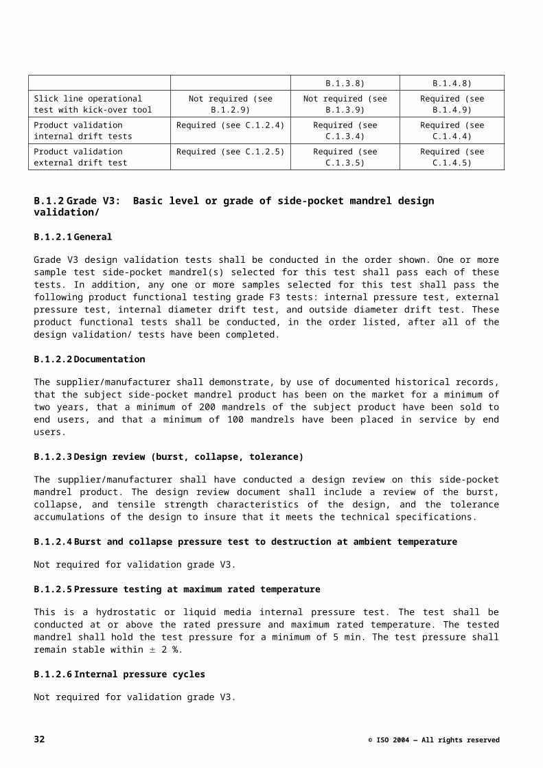
Annex D (normative)
Quality control requirements
D.1 Purpose
D.1.1 General
Each quality control grade requires a number of individual procedure(s), process(s), or test(s). The results of all of these shall be maintained in manufacturing or quality control files.
Table 1 — Quality control grade
Q3 Q2 Q1
Hardness testing 100 % (see D.1.2.1) 100 % (see D.1.3.1) 100 % (see D.1.4.1)
Non-destructive examination Not required (see D.1.2.2) 5 % (see D.1.3.2) 100 % (see D.1.4.2)
For Q2, select one preferred method from the four listed methods of non-destructive testing.
For Q1, radiographic examination is required.
Surface magnetic particle examination.
Liquid penetrant examination.
Radiographic examination.
Ultrasonic examination.
Documentationa 100 % COCb (see D.1.2.3) 100 % COC plusc (see D.1.3.3)
100 % COC plusc (see D.1.4.3)
a Documentation shall be supplied if it is required by the user/purchaser. b COC = Certification of conformancec Plus = Additional requirements.
D.1.2 Grade Q3: Basic level or grade of side-pocket mandrel quality control
D.1.2.1 Hardness testing
The hardness of the side-pocket mandrel shall be determined at a minimum of two locations – one near the upper and one near the lower ends of the side-pocket upset area. This test shall be conducted on 100 % of the mandrels in each job lot. All hardness examinations shall be conducted in accordance with 7.7.5.
D.1.2.2 Non-destructive examination
Not required for quality control level Q3.
D.1.2.3 Documentation
If it is required by the user/purchaser, the documentation shall include a certificate of conformance for the side-pocket mandrel job lot.
© ISO 2004 — All rights reserved 33
D.1.3 Grade Q2: Intermediate level or grade of side-pocket mandrel quality control
D.1.3.1 Hardness testing
The hardness of the side-pocket mandrel shall be determined at a minimum of three locations – one near the upper and one near the lower ends of the side-pocket upset area, and in one weld zone. This test shall be conducted on 100 % of the mandrels in each job lot. All hardness examinations shall be conducted in accordance with 7.7.5.
D.1.3.2 Non-destructive examination
For quality control level Q2, one of the following four tests shall be performed as specified by supplier/manufacturer. It shall be performed on 5 % of the side-pocket mandrels of each job lot. The sampling process shall be in accordance with 7.7.1.
Magnetic particle examination shall be in accordance with 7.7.8.
Liquid penetrant examination shall be in accordance with 7.7.9.
Radiographic examination shall be in accordance with 7.7.6.
Ultrasonic examination shall be in accordance with 7.7.7.
D.1.3.3 Documentation
If it is required by the user/purchaser, the documentation shall include a certificate of conformance for the side-pocket mandrel job lot. It shall also contain additional NDE and mill certification for supplier/manufacturer-specified critical components as specified in 7.4.6.
D.1.4 Grade Q1: Highest level or grade of side-pocket mandrel quality control
D.1.4.1 Hardness testing
The hardness of the side-pocket mandrel shall be determined at a minimum of four locations – one near the upper, one near the middle, and one near the lower ends of the side-pocket upset area, and in one weld zone. This test shall be conducted on 100 % of the mandrels in each job lot. All hardness examinations shall be conducted in accordance with 7.7.5.
D.1.4.2 Non-destructive examination
One hundred percent (100 %) radiographic examination required of the side-pocket mandrels of each job lot shall be tested in accordance with 7.7.6.
D.1.4.3 Documentation
If it is required by the user/purchaser, the documentation shall include a certificate of conformance for the side-pocket mandrel job lot. It shall also contain additional NDE and mill certification for all components as specified in 7.4.6.
34 © ISO 2004 — All rights reserved
Annex E (informative)
Operating performance envelope
E.1Purpose
This side-pocket mandrel operating performance envelope is based on a plot of Pressure on the "Y" axis and Axial Load on the "X" axis. At the center of the plot, both the pressure and axial load are 0,0. An increase in pressure (increase in the "Y" axis) indicates an increase in the burst pressure; a decrease is an increase in the collapse pressure. An increase in the axial load (increase in the "X" axis) indicates an increase in the tensile load; a decrease is an increase in the compressive load. To consider maximum operating temperature, the combination of pressure and load shall plot within the inner "gray" envelop.
© ISO 2004 — All rights reserved 35
Figure 1 — Operating pressure envelope
NOTE With respect to compressive loading, diagrams such as this on non-circular cross-sections (e.g. oval configurations) are not feasible without specific tests.
36 © ISO 2004 — All rights reserved
Annex F (informative)
Schematics of Side-Pocket Mandrels
F.1General
The following drawings illustrate typical side pocket mandrels.
© ISO 2004 — All rights reserved 37
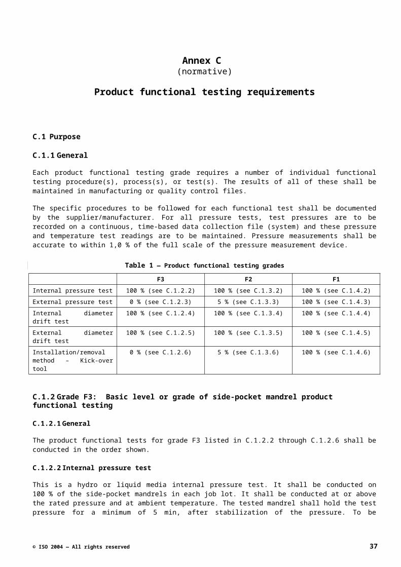
38 © ISO 2004 — All rights reserved
Bibliography
[1] ISO/IEC Guide 22:1996, General criteria for supplier's declaration of conformity
[2] ISO31-0: 1992, Quantities and units — Part 0: General principles
[3] ISO 31-3:1992, Quantities and units — Part 3: Mechanics
[4] ISO 11960:2001 Petroleum and natural gas industries — Steel pipes for use as casing or tubing for wells
[5] API RP 11V5: 1999, Operation, Maintenance, and Troubleshooting of Gas-Lift Installations
[6] API RP 11V6: 1999, Design of Continuous Flow Gas Lift Installations Using Injection Pressure Operated Valves
[7] API RP 11V8: 2004, Recommended Practice for Gas Lift System Design and Performance Prediction
© ISO 2004 — All rights reserved 39