Embed Size (px)
DESCRIPTION
Isophase Bus Ducts Erection Guide and Principles
Citation preview
COMMESSA / Job N. 2975
SPC N. 2975 MP18
Fg - Sh./ di-of Rev.
INSTALLATION OPERATING & MAINTENANCE MANUAL
1 / 41 0
CLIENTE / Customer
ROCKSON ENGINEERING ORDINE CLIENTE / Purchase order N.
/LOCALITA’ / Plant Location
ALAOJI (NIGERIA)IMPIANTO / Plant
ALAOJI POWER PLANT PROJECT EQUIPAGGIAMENTO / Equipment
ISOLATED PHASE BUS DUCT (GAS TURBINE)
0 Emissione / Issue Chiodi Redaelli Abbiati 15.10.’07Rev Descrizione / Description Comp./Prep. ‘d Ver / Chk’d App. / Appr’d Data / Date
Questo documento dovrà essere utilizzato solo per gli scopi indicati nel contratto. Alfa Standard tutelerà i propri diritti a termine di Legge.
This document shall be utilized for the scope set forth in the contract for which it has been issued. Alfa Standard will safeguard its rights according to the law.
COMMESSA / Job N. 2975
SPC N. 2975 MP18
Fg - Sh./ di-of Rev.
INSTALLATION OPERATING & MAINTENANCE MANUAL
2 / 41 0
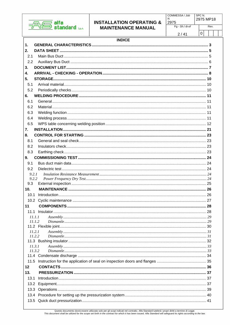
INDICE 1. GENERAL CHARACTERISTICS ............................................................................................................. 3 2. DATA SHEET ........................................................................................................................................... 5
2.1 Main Bus Duct ....................................................................................................................................... 5 2.2 Auxiliary Bus Duct ................................................................................................................................. 6
3. DOCUMENT LIST..................................................................................................................................... 7 4. ARRIVAL - CHECKING - OPERATION................................................................................................... 8 5. STORAGE............................................................................................................................................... 10
5.1 Arrival material..................................................................................................................................... 10 5.2 Periodically checks .............................................................................................................................. 10
6. WELDING PROCEDURE ....................................................................................................................... 11 6.1 General ................................................................................................................................................ 11 6.2 Material ................................................................................................................................................ 11 6.3 Welding function .................................................................................................................................. 11 6.4 Welding process .................................................................................................................................. 11 6.5 WPS table concerning welding position .............................................................................................. 12
7. INSTALLATION...................................................................................................................................... 21 8. CONTROL FOR STARTING .................................................................................................................. 23
8.1 General and seal check....................................................................................................................... 23 8.2 Insulators check................................................................................................................................... 23 8.3 Earthing check..................................................................................................................................... 23
9. COMMISSIONING TEST........................................................................................................................ 24 9.1 Bus duct main data.............................................................................................................................. 24 9.2 Dielectric test ....................................................................................................................................... 24
9.2.1 Insulation Resistance Measurement .............................................................................................................. 24 9.2.2 Power Frequency Dry Test............................................................................................................................ 24
9.3 External inspection .............................................................................................................................. 25 10. MAINTENANCE ................................................................................................................................. 26
10.1 Introduction.......................................................................................................................................... 26 10.2 Cyclic maintenance ............................................................................................................................. 27
11 COMPONENTS .................................................................................................................................. 28 11.1 Insulator ............................................................................................................................................... 28
11.1.1 Assembly ................................................................................................................................................... 29 11.1.2 Dismantle.................................................................................................................................................. 29
11.2 Flexible joint......................................................................................................................................... 30 11.2.1 Assembly ................................................................................................................................................... 31 11.2.2 Dismantle.................................................................................................................................................. 31
11.3 Bushing insulator ................................................................................................................................. 32 11.3.1 Assembly ................................................................................................................................................... 33 11.3.2 Dismantle.................................................................................................................................................. 33
11.4 Condensate discharge ........................................................................................................................ 34 11.5 Instruction for the application of seal on inspection doors and flanges .............................................. 35
12 CONTACTS........................................................................................................................................ 36 13. PRESSURIZATION ............................................................................................................................ 37
13.1 Introduction.......................................................................................................................................... 37 13.2 Equipment............................................................................................................................................ 37 13.3 Operations ........................................................................................................................................... 39 13.4 Procedure for setting up the pressurization system............................................................................ 40 13.5 Quick duct pressurization .................................................................................................................... 41
Questo documento dovrà essere utilizzato solo per gli scopi indicati nel contratto. Alfa Standard tutelerà i propri diritti a termine di Legge. This document shall be utilized for the scope set forth in the contract for which it has been issued. Alfa Standard will safeguard its rights according to the law.

COMMESSA / Job N. 2975
SPC N. 2975 MP18
Fg - Sh./ di-of Rev.
INSTALLATION OPERATING & MAINTENANCE MANUAL
3 / 41 0
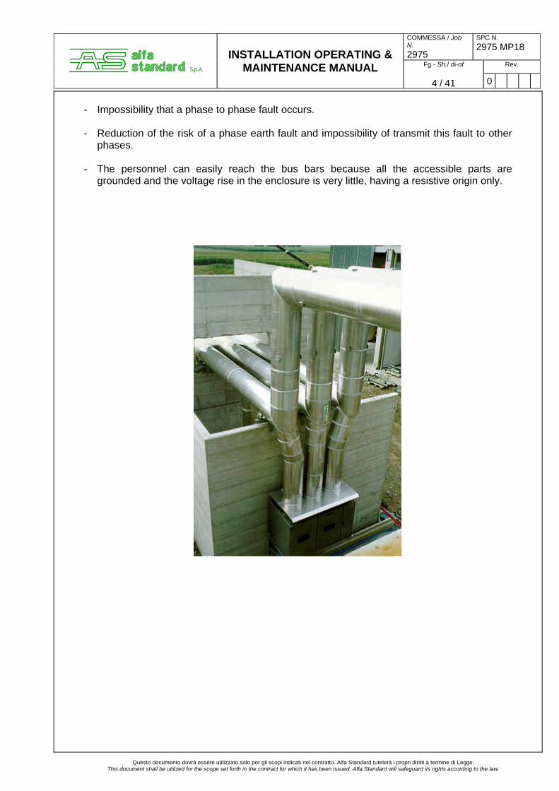
1. GENERAL CHARACTERISTICS
The bus duct are Isolated Phases Bus type, this means that each phase conductor is enclosed in an individual, non magnetic metal housing, separated from the housing of the adjacent conductor by an air gap. The conductors are cylinders made of pure aluminium and are supported in a radial way by insulators. The enclosures are electrically bonded together at the extremities and earthed (normally in only one point). This design permits the induced currents to flow in each enclosure with an intensity close to the one of the phase current of the conductor (90 ÷ 98%), but in the opposite direction. This reduces the flux outside the enclosure by about 95% both under normal and fault conditions and therefore:
- Eliminates the forces between conductors of adjacent phases and reduces the forces in bends and other discontinuities.
- Cancels the induction effect of the currents i.e. heating and losses in the nearby
components such as steelworks, cables, pipes... Associated to the fully welded design of enclosure and the conductors, this type of bus duct also offers other advantages such as: - Possibility of large unsupported spans due to the high moment of inertia of the cylindrical
shaped, seams welded aluminium enclosure.
Questo documento dovrà essere utilizzato solo per gli scopi indicati nel contratto. Alfa Standard tutelerà i propri diritti a termine di Legge. This document shall be utilized for the scope set forth in the contract for which it has been issued. Alfa Standard will safeguard its rights according to the law.
COMMESSA / Job N. 2975
SPC N. 2975 MP18
Fg - Sh./ di-of Rev.
INSTALLATION OPERATING & MAINTENANCE MANUAL
4 / 41 0
- Impossibility that a phase to phase fault occurs. - Reduction of the risk of a phase earth fault and impossibility of transmit this fault to other
phases. - The personnel can easily reach the bus bars because all the accessible parts are
grounded and the voltage rise in the enclosure is very little, having a resistive origin only.
Questo documento dovrà essere utilizzato solo per gli scopi indicati nel contratto. Alfa Standard tutelerà i propri diritti a termine di Legge.
This document shall be utilized for the scope set forth in the contract for which it has been issued. Alfa Standard will safeguard its rights according to the law.
COMMESSA / Job N. 2975
SPC N. 2975 MP18
Fg - Sh./ di-of Rev.
INSTALLATION OPERATING & MAINTENANCE MANUAL
5 / 41 0
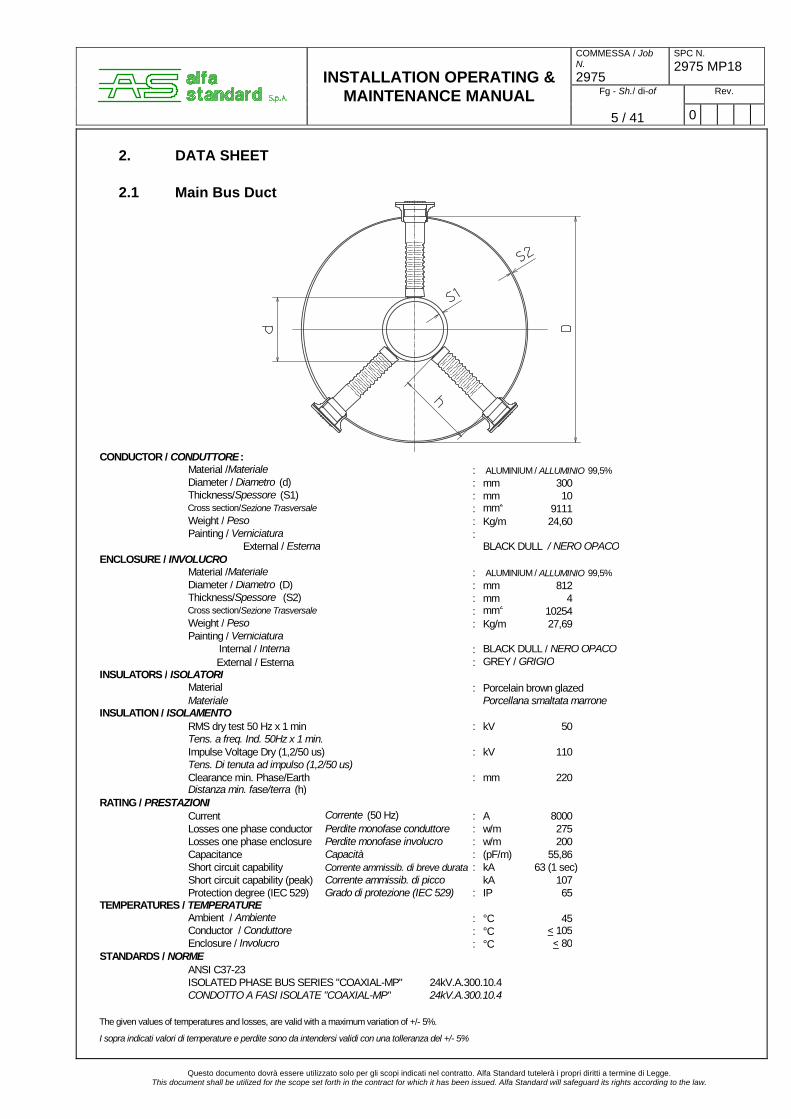
2. DATA SHEET
2.1 Main Bus Duct
CONDUCTOR / CONDUTTORE:
Material /Materiale :Diameter / Diametro (d) : mm 300Thickness/Spessore (S1) : mm 10Cross section/Sezione Trasversale : mm2 9111Weight / Peso : Kg/m 24,60Painting / Verniciatura : External / Esterna BLACK DULL / NERO OPACO
ENCLOSURE / INVOLUCROMaterial /Materiale :Diameter / Diametro (D) : mm 812Thickness/Spessore (S2) : mm 4Cross section/Sezione Trasversale : mm2 10254Weight / Peso : Kg/m 27,69Painting / Verniciatura
Internal / Interna : BLACK DULL / NERO OPACOExternal / Esterna : GREY / GRIGIO
INSULATORS / ISOLATORIMaterial : Porcelain brown glazedMateriale Porcellana smaltata marrone
INSULATION / ISOLAMENTO RMS dry test 50 Hz x 1 min : kV 50Tens. a freq. Ind. 50Hz x 1 min.Impulse Voltage Dry (1,2/50 us) : kV 110Tens. Di tenuta ad impulso (1,2/50 us)Clearance min. Phase/Earth : mm 220Distanza min. fase/terra (h)
RATING / PRESTAZIONI Current Corrente (50 Hz) : A 8000Losses one phase conductor Perdite monofase conduttore : w/m 275Losses one phase enclosure Perdite monofase involucro : w/m 200Capacitance Capacità : (pF/m) 55,86Short circuit capability Corrente ammissib. di breve durata : kA 63 (1 sec)Short circuit capability (peak) Corrente ammissib. di picco kA 107Protection degree (IEC 529) Grado di protezione (IEC 529) : IP 65
TEMPERATURES / TEMPERATUREAmbient / Ambiente : °C 45Conductor / Conduttore : °C < 105Enclosure / Involucro : °C < 80
STANDARDS / NORME ANSI C37-23ISOLATED PHASE BUS SERIES "COAXIAL-MP" 24kV.A.300.10.4CONDOTTO A FASI ISOLATE "COAXIAL-MP" 24kV.A.300.10.4
The given values of temperatures and losses, are valid with a maximum variation of +/- 5%.
I sopra indicati valori di temperature e perdite sono da intendersi validi con una tolleranza del +/- 5%
ALUMINIUM / ALLUMINIO 99,5%
ALUMINIUM / ALLUMINIO 99,5%
Questo documento dovrà essere utilizzato solo per gli scopi indicati nel contratto. Alfa Standard tutelerà i propri diritti a termine di Legge. This document shall be utilized for the scope set forth in the contract for which it has been issued. Alfa Standard will safeguard its rights according to the law.

COMMESSA / Job N. 2975
SPC N. 2975 MP18
Fg - Sh./ di-of Rev.
INSTALLATION OPERATING & MAINTENANCE MANUAL
6 / 41 0
2.2 Auxiliary Bus Duct
CONDUCTOR / CONDUTTORE :Material /Materiale :Diameter / Diametro (d) : mm 100Thickness/Spessore (S1) : mm 10Cross section/Sezione Trasversale : mm2 2827Weight / Peso : Kg/m 7,63Painting / Verniciatura : External / Esterna BLACK DULL / NERO OPACO
ENCLOSURE / INVOLUCROMaterial /Materiale :Diameter / Diametro (D) : mm 594Thickness/Spessore (S2) : mm 3Cross section/Sezione Trasversale : mm2 5627Weight / Peso : Kg/m 15,19Painting / Verniciatura
Internal / Interna : BLACK DULL / NERO OPACOExternal / Esterna : GREY / GRIGIO
INSULATORS / ISOLATORIMaterial : Porcelain brown glazedMateriale Porcellana smaltata marrone
INSULATION / ISOLAMENTO RMS dry test 50 Hz x 1 min : kV 50Tens. a freq. Ind. 50Hz x 1 min.Impulse Voltage Dry (1,2/50 us) : kV 110Tens. Di tenuta ad impulso (1,2/50 us)Clearance min. Phase/Earth : mm 220Distanza min. fase/terra (h)
RATING / PRESTAZIONI Current Corrente (50 Hz) : A 1200Losses one phase conductor Perdite monofase conduttore : w/m 15Losses one phase enclosure Perdite monofase involucro : w/m 7Capacitance Capacità : (pF/m) 31,22Short circuit capability Corrente ammissib. di breve durata : kA 100 (1 sec)Short circuit capability (peak) Corrente ammissib. di picco kA 170Protection degree (IEC 529) Grado di protezione (IEC 529) : IP 65
TEMPERATURES / TEMPERATUREAmbient / Ambiente : °C 45Conductor / Conduttore : °C < 55Enclosure / Involucro : °C < 48
STANDARDS / NORME ANSI C37-23ISOLATED PHASE BUS SERIES "COAXIAL-MP" 24kV.A.100.10.3CONDOTTO A FASI ISOLATE "COAXIAL-MP" 24kV.A.100.10.3
The given values of temperatures and losses, are valid with a maximum variation of +/- 5%.
I sopra indicati valori di temperature e perdite sono da intendersi validi con una tolleranza del +/- 5%
ALUMINIUM / ALLUMINIO 99,5%
ALUMINIUM / ALLUMINIO 99,5%
Questo documento dovrà essere utilizzato solo per gli scopi indicati nel contratto. Alfa Standard tutelerà i propri diritti a termine di Legge.
This document shall be utilized for the scope set forth in the contract for which it has been issued. Alfa Standard will safeguard its rights according to the law.

COMMESSA / Job N. 2975
SPC N. 2975 MP18
Fg - Sh./ di-of Rev.
INSTALLATION OPERATING & MAINTENANCE MANUAL
7 / 41 0
3. DOCUMENT LIST
PO
S.
DESCRIPTION A.S. N°
1 GENERAL ARRANGEMENT (GAS TURBINE) ANDAMENTO GENERALE CTG 2975 MP5
2 CIVIL WORK DISPOSITION (GAS TURBINE) DISPOSIZIONE OPERA CIVILE CTG 2975 MP6
3 CONNECTION TO MAIN TRANSFORMER COLLEGAMENTO AL TRASF. PRINCIPALE 2975 MP7
4 CONNECTION TO AUX. TRANSFORMER COLLEGAMENTO AL TRASF. AUSILIARIO 2975 MP8
5 CONNECTION TO CIRCUIT BREAKER COLLEGAMENTO ALL’INTERRUTTORE 2975 MP9
6 PRESSURIZATION SYSTEM SISTEMA DI PRESSURIZZAZIONE 2975 MP10
7 SUPPORT STEEL WORK TRANSFORMER SIDE CARPENTERIA ZONA TRASFORMATORE 2975 MP11
8 SUPPORT STEEL WORK CIRCUIT BREAKER SIDE CARPENTERIA ZONA INTERRUTTORE 2975 MP12
9 TYPICAL DETAILS DETTAGLI TIPICI 2975 MP13
10 ISOMETRIC GENERAL ARRANGEMENT DRAWING (3D) ANDAMENTO GENERALE IN 3D 2975 MP14
11 MATERIAL LIST LISTA MATERIALI 2975 MP15
12 SPARE PARTS PARTI DI RICAMBIO 2975 MP16
Questo documento dovrà essere utilizzato solo per gli scopi indicati nel contratto. Alfa Standard tutelerà i propri diritti a termine di Legge.
This document shall be utilized for the scope set forth in the contract for which it has been issued. Alfa Standard will safeguard its rights according to the law.

COMMESSA / Job N. 2975
SPC N. 2975 MP18
Fg - Sh./ di-of Rev.
INSTALLATION OPERATING & MAINTENANCE MANUAL
8 / 41 0
4. ARRIVAL - CHECKING - OPERATION All the material regarding the bus bars is held in cases for transport.
The materials have the identification number as shown on the relevant drawings. For each case there is a relevant “packing list” that sums up the contained materials. All the positions referring to every design are compiled in the document named “Material List”. All the cases for transport enclose a “Packing List”, in witch it’s referred the contents of the case. For the material reception go on with the following points: - Verify the integrity of the packing and the materials. - Verify that the Packing List corresponds with the goods inside the cases. - Verify the disponibility of the technical documents necessary for the work, in the suitable
issue.
Questo documento dovrà essere utilizzato solo per gli scopi indicati nel contratto. Alfa Standard tutelerà i propri diritti a termine di Legge. This document shall be utilized for the scope set forth in the contract for which it has been issued. Alfa Standard will safeguard its rights according to the law.
COMMESSA / Job N. 2975
SPC N. 2975 MP18
Fg - Sh./ di-of Rev.
INSTALLATION OPERATING & MAINTENANCE MANUAL
9 / 41 0
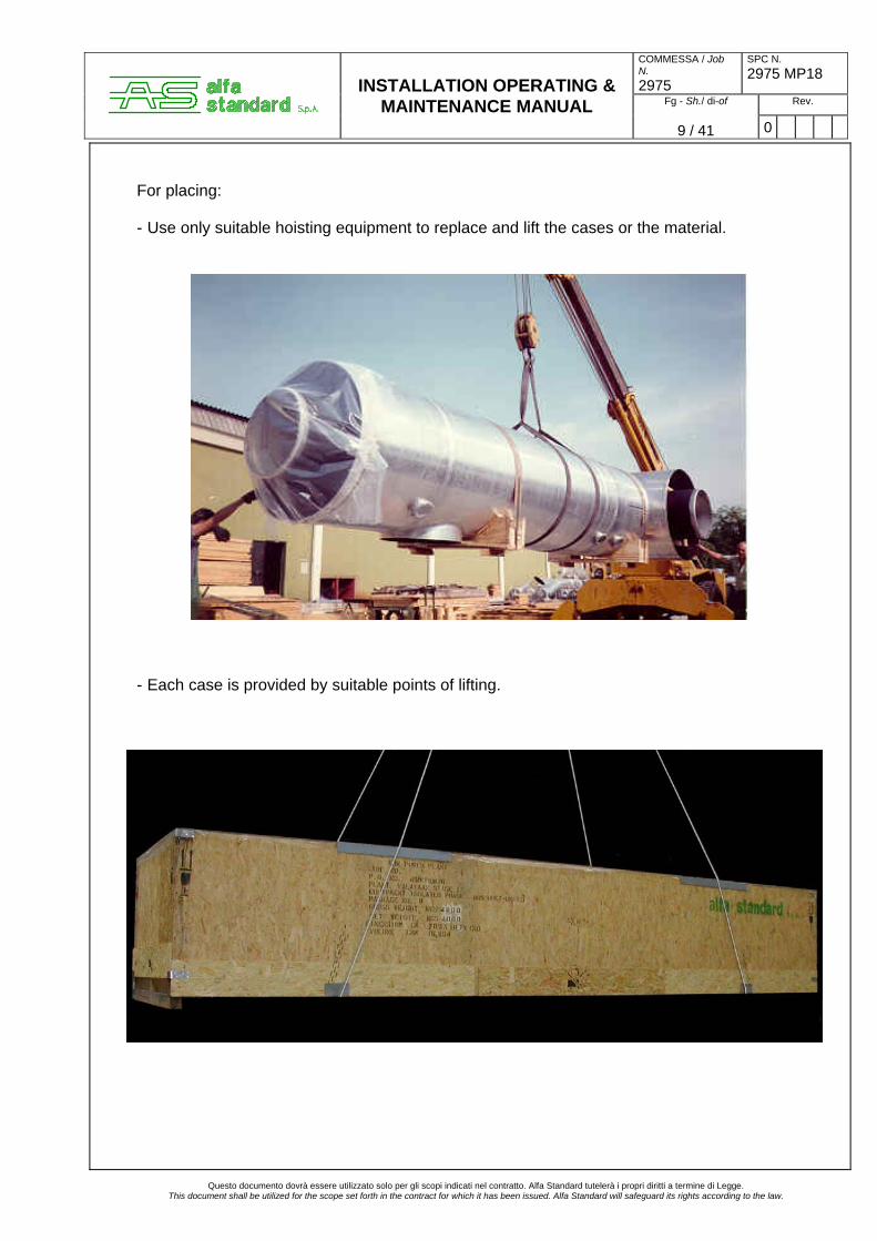
For placing: - Use only suitable hoisting equipment to replace and lift the cases or the material.
- Each case is provided by suitable points of lifting.
Questo documento dovrà essere utilizzato solo per gli scopi indicati nel contratto. Alfa Standard tutelerà i propri diritti a termine di Legge.
This document shall be utilized for the scope set forth in the contract for which it has been issued. Alfa Standard will safeguard its rights according to the law.

COMMESSA / Job N. 2975
SPC N. 2975 MP18
Fg - Sh./ di-of Rev.
INSTALLATION OPERATING & MAINTENANCE MANUAL
10 / 41 0
5. STORAGE 5.1 Arrival material The material that can arrive on site will be of the following type:
- Pieces of bus duct (photo n°1). - Cubicles (painted steel) (photo n°2) - Accessories: bolts, nut, flexibles, braids, bushing, insulators (photo n°3) - Steel work (galvanized).
Foto n°1 Foto n°2
Foto n°3
All the material will arrive into the cases. These cases will be stored indoor or outdoor but protected against rain. The cases containing cubicles and / or equipment (i.e., PT’s, CT’s, etc.) must be stored indoor. It is not necessary conditioning air or similar, the material into the cases is protect against corrosion. 5.2 Periodically checks If the material must be stored outdoor for a long period, it is recommended to check the integrity of the cases (every 6 - six - months).
Questo documento dovrà essere utilizzato solo per gli scopi indicati nel contratto. Alfa Standard tutelerà i propri diritti a termine di Legge.
This document shall be utilized for the scope set forth in the contract for which it has been issued. Alfa Standard will safeguard its rights according to the law.
COMMESSA / Job N. 2975
SPC N. 2975 MP18
Fg - Sh./ di-of Rev.
INSTALLATION OPERATING & MAINTENANCE MANUAL
11 / 41 0
6. WELDING PROCEDURE 6.1 General The scope of this procedure is to assure the constant quality and electric conductivity of weldings on Aluminium pipes as “enclosure” and / or “conductor” of bus duct.” 6.2 Material The material to be welded can be: - Aluminium 99,5 (UNI 9001 - ISO 1050 / A) - Copper 99,9 % (UNI 5649) for conductors (if applicable). 6.3 Welding function The welding function is to assure the electric continuity and the mechanical strength, however the welding section must be not less than 100% of the conductor/enclosure nominal square section. - Ensuring the Quality of welding work, supplier and on site. Weldig work shall only be carried out by welders qualified in accordance with ASME code
qualification as per section 9, QW-461. - Checks Complete welded seams are to be visually checked that they conform to the drawings. They are also to be checked that they conform to item 6.5 Acceptability criteria of this
specification. 6.4 Welding process The welding process to be used will be the Metal Inert Gas (MIG) with filler metal wire equal to the base metal. Welding machine : DC current reversed polarity Inert Gas : Argon The data for the welding are: - for conductor : Aluminium WPS Al118/05, Al 119/05, Al 121/05 - for enclosure : Aluminium WPS Al 107/05, Al 110/05, Al 111/05, Al 115/05, Al 123/05
Questo documento dovrà essere utilizzato solo per gli scopi indicati nel contratto. Alfa Standard tutelerà i propri diritti a termine di Legge.
This document shall be utilized for the scope set forth in the contract for which it has been issued. Alfa Standard will safeguard its rights according to the law.

COMMESSA / Job N. 2975
SPC N. 2975 MP18
Fg - Sh./ di-of Rev.
INSTALLATION OPERATING & MAINTENANCE MANUAL
12 / 41 0
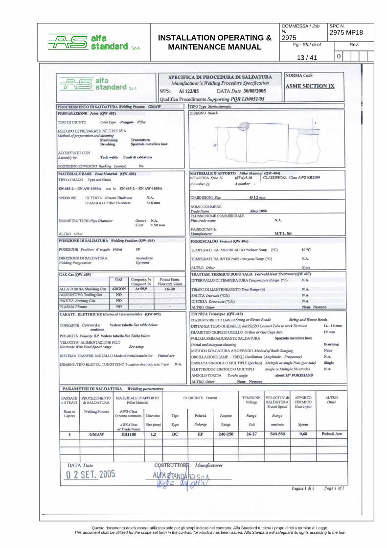
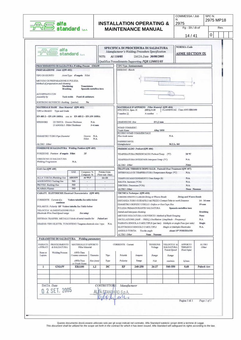
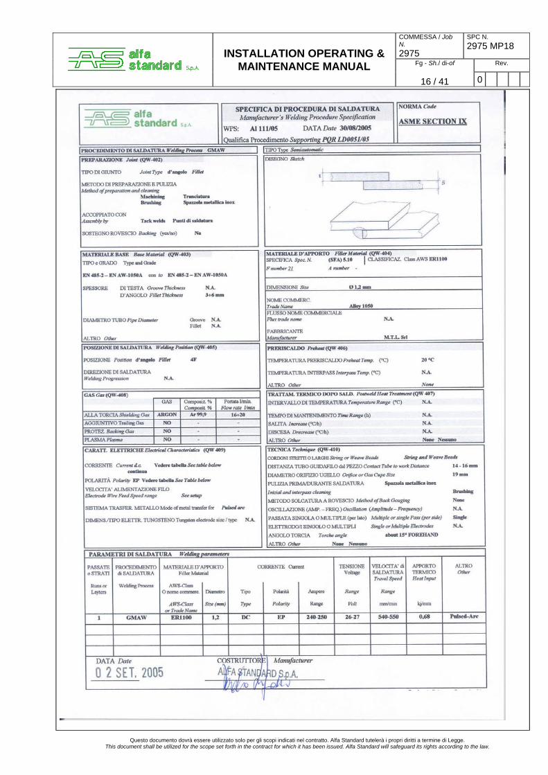
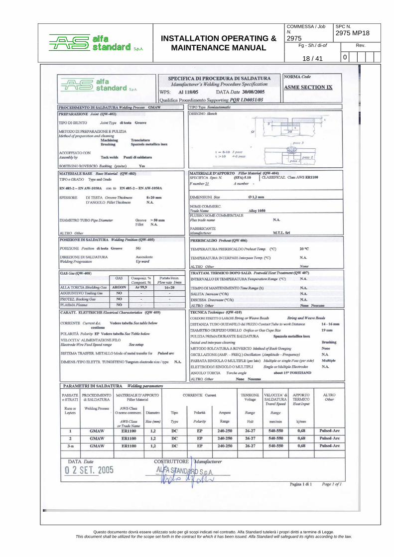
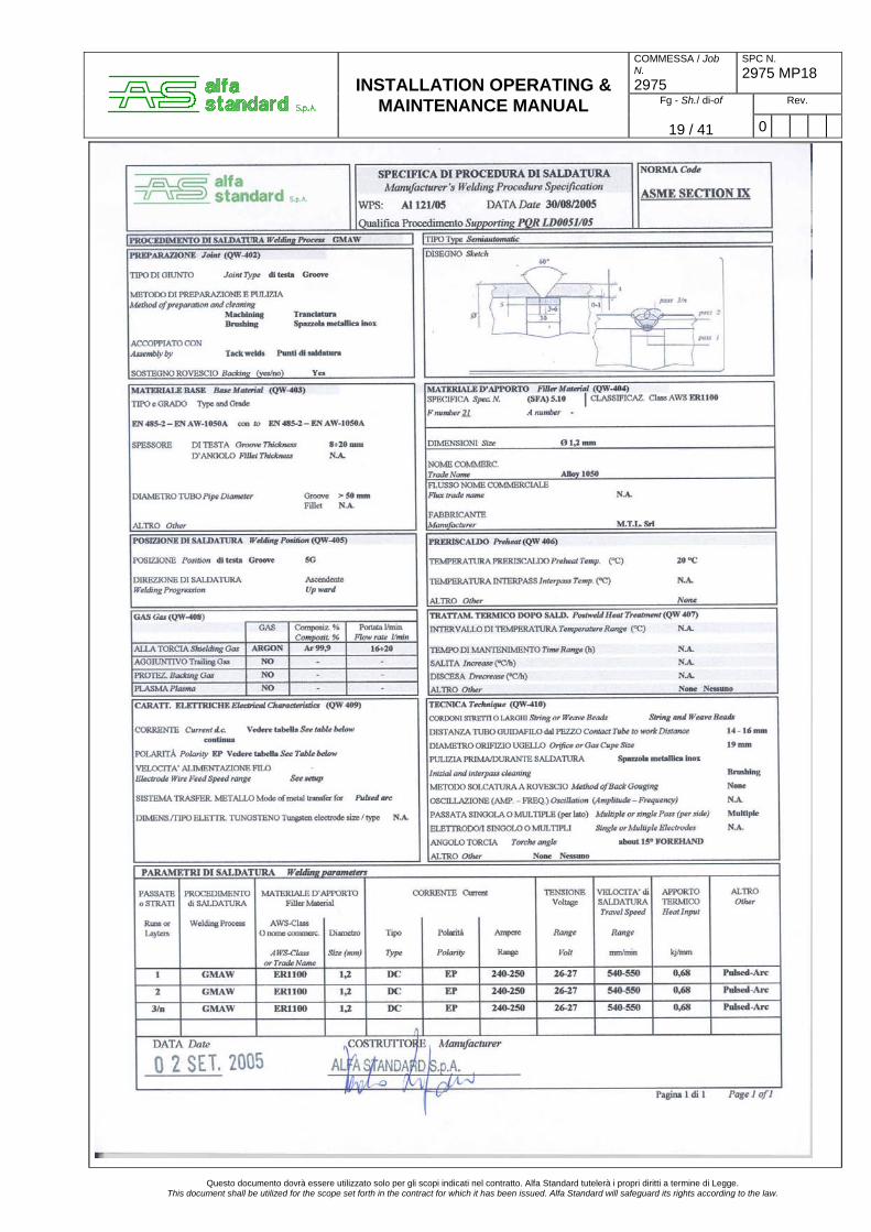
6.5 WPS table concerning welding position
(WPS) Welding position 3÷6
5F
Al 123/05
2F
Al 110/05
1G
Al 107/05
4F
Al 111/05
- For enclosure
(see figure1)
5G
Al 115/05
8÷20
5G Al 118/05 Al 121/05
- For conductor
(see figure2)
2G
Al 119/05
Note: 1) = welding grafic sign. 2) For WPS, see attached on this manual.
Questo documento dovrà essere utilizzato solo per gli scopi indicati nel contratto. Alfa Standard tutelerà i propri diritti a termine di Legge.
This document shall be utilized for the scope set forth in the contract for which it has been issued. Alfa Standard will safeguard its rights according to the law.
Figura 2 Conductor: Front view
5F V5F V 1G V
2F V
4F V
5G V
5G V
2G V
Figura 1 Enclosure: Front view
COMMESSA / Job N. 2975
SPC N. 2975 MP18
Fg - Sh./ di-of Rev.
INSTALLATION OPERATING & MAINTENANCE MANUAL
13 / 41 0
Questo documento dovrà essere utilizzato solo per gli scopi indicati nel contratto. Alfa Standard tutelerà i propri diritti a termine di Legge. This document shall be utilized for the scope set forth in the contract for which it has been issued. Alfa Standard will safeguard its rights according to the law.
COMMESSA / Job N. 2975
SPC N. 2975 MP18
Fg - Sh./ di-of Rev.
INSTALLATION OPERATING & MAINTENANCE MANUAL
14 / 41 0
Questo documento dovrà essere utilizzato solo per gli scopi indicati nel contratto. Alfa Standard tutelerà i propri diritti a termine di Legge. This document shall be utilized for the scope set forth in the contract for which it has been issued. Alfa Standard will safeguard its rights according to the law.

COMMESSA / Job N. 2975
SPC N. 2975 MP18
Fg - Sh./ di-of Rev.
INSTALLATION OPERATING & MAINTENANCE MANUAL
15 / 41 0
Questo documento dovrà essere utilizzato solo per gli scopi indicati nel contratto. Alfa Standard tutelerà i propri diritti a termine di Legge. This document shall be utilized for the scope set forth in the contract for which it has been issued. Alfa Standard will safeguard its rights according to the law.
COMMESSA / Job N. 2975
SPC N. 2975 MP18
Fg - Sh./ di-of Rev.
INSTALLATION OPERATING & MAINTENANCE MANUAL
16 / 41 0
Questo documento dovrà essere utilizzato solo per gli scopi indicati nel contratto. Alfa Standard tutelerà i propri diritti a termine di Legge. This document shall be utilized for the scope set forth in the contract for which it has been issued. Alfa Standard will safeguard its rights according to the law.

COMMESSA / Job N. 2975
SPC N. 2975 MP18
Fg - Sh./ di-of Rev.
INSTALLATION OPERATING & MAINTENANCE MANUAL
17 / 41 0
Questo documento dovrà essere utilizzato solo per gli scopi indicati nel contratto. Alfa Standard tutelerà i propri diritti a termine di Legge.
This document shall be utilized for the scope set forth in the contract for which it has been issued. Alfa Standard will safeguard its rights according to the law.
COMMESSA / Job N. 2975
SPC N. 2975 MP18
Fg - Sh./ di-of Rev.
INSTALLATION OPERATING & MAINTENANCE MANUAL
18 / 41 0
Questo documento dovrà essere utilizzato solo per gli scopi indicati nel contratto. Alfa Standard tutelerà i propri diritti a termine di Legge.
This document shall be utilized for the scope set forth in the contract for which it has been issued. Alfa Standard will safeguard its rights according to the law.
COMMESSA / Job N. 2975
SPC N. 2975 MP18
Fg - Sh./ di-of Rev.
INSTALLATION OPERATING & MAINTENANCE MANUAL
19 / 41 0
Questo documento dovrà essere utilizzato solo per gli scopi indicati nel contratto. Alfa Standard tutelerà i propri diritti a termine di Legge. This document shall be utilized for the scope set forth in the contract for which it has been issued. Alfa Standard will safeguard its rights according to the law.

COMMESSA / Job N. 2975
SPC N. 2975 MP18
Fg - Sh./ di-of Rev.
INSTALLATION OPERATING & MAINTENANCE MANUAL
20 / 41 0
Questo documento dovrà essere utilizzato solo per gli scopi indicati nel contratto. Alfa Standard tutelerà i propri diritti a termine di Legge. This document shall be utilized for the scope set forth in the contract for which it has been issued. Alfa Standard will safeguard its rights according to the law.
COMMESSA / Job N. 2975
SPC N. 2975 MP18
Fg - Sh./ di-of Rev.
INSTALLATION OPERATING & MAINTENANCE MANUAL
21 / 41 0
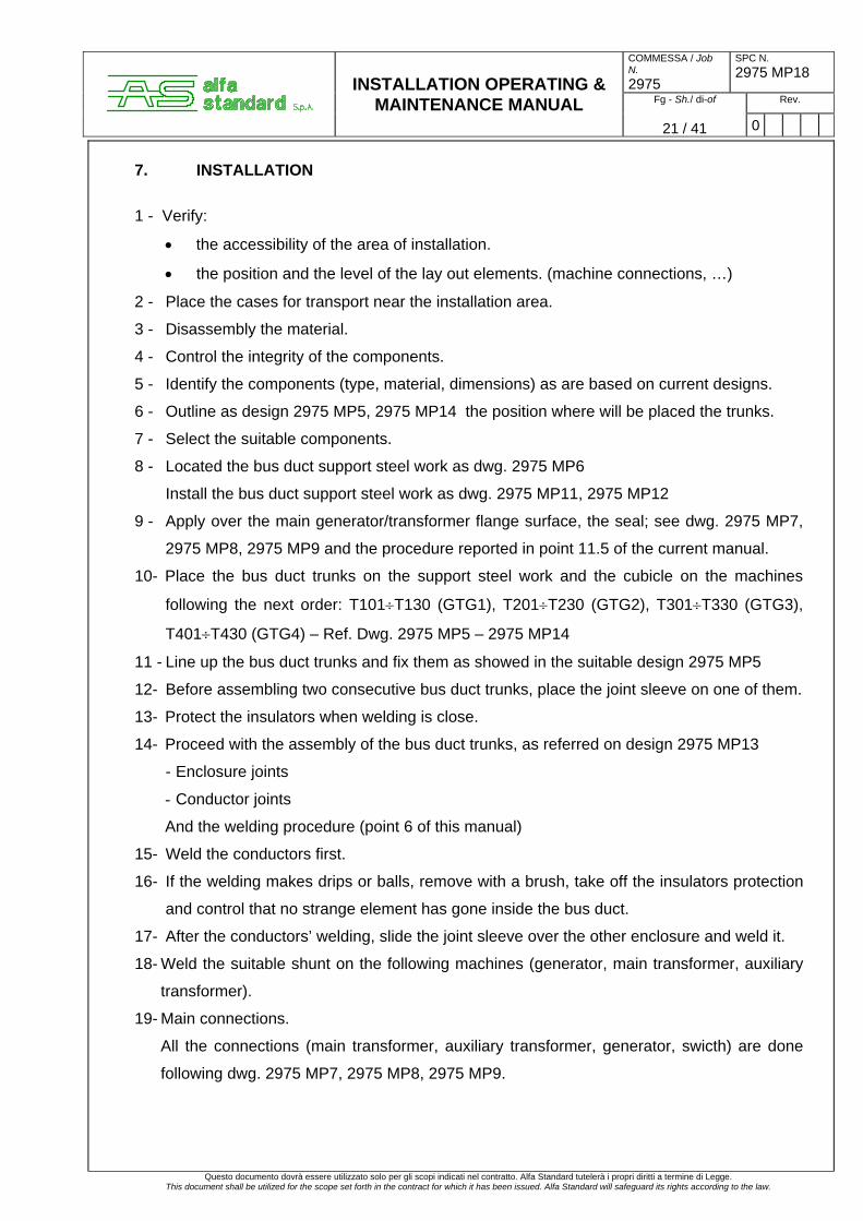
7. INSTALLATION
1 - Verify:
• the accessibility of the area of installation.
• the position and the level of the lay out elements. (machine connections, …)
2 - Place the cases for transport near the installation area.
3 - Disassembly the material.
4 - Control the integrity of the components.
5 - Identify the components (type, material, dimensions) as are based on current designs.
6 - Outline as design 2975 MP5, 2975 MP14 the position where will be placed the trunks.
7 - Select the suitable components. 8 - Located the bus duct support steel work as dwg. 2975 MP6
Install the bus duct support steel work as dwg. 2975 MP11, 2975 MP12
9 - Apply over the main generator/transformer flange surface, the seal; see dwg. 2975 MP7,
2975 MP8, 2975 MP9 and the procedure reported in point 11.5 of the current manual.
10- Place the bus duct trunks on the support steel work and the cubicle on the machines
following the next order: T101÷T130 (GTG1), T201÷T230 (GTG2), T301÷T330 (GTG3),
T401÷T430 (GTG4) – Ref. Dwg. 2975 MP5 – 2975 MP14
11 - Line up the bus duct trunks and fix them as showed in the suitable design 2975 MP5
12- Before assembling two consecutive bus duct trunks, place the joint sleeve on one of them.
13- Protect the insulators when welding is close.
14- Proceed with the assembly of the bus duct trunks, as referred on design 2975 MP13
- Enclosure joints
- Conductor joints
And the welding procedure (point 6 of this manual)
15- Weld the conductors first.
16- If the welding makes drips or balls, remove with a brush, take off the insulators protection
and control that no strange element has gone inside the bus duct.
17- After the conductors’ welding, slide the joint sleeve over the other enclosure and weld it.
18- Weld the suitable shunt on the following machines (generator, main transformer, auxiliary
transformer).
19- Main connections.
All the connections (main transformer, auxiliary transformer, generator, swicth) are done
following dwg. 2975 MP7, 2975 MP8, 2975 MP9.
Questo documento dovrà essere utilizzato solo per gli scopi indicati nel contratto. Alfa Standard tutelerà i propri diritti a termine di Legge. This document shall be utilized for the scope set forth in the contract for which it has been issued. Alfa Standard will safeguard its rights according to the law.

COMMESSA / Job N. 2975
SPC N. 2975 MP18
Fg - Sh./ di-of Rev.
INSTALLATION OPERATING & MAINTENANCE MANUAL
22 / 41 0
20- Auxiliary connections.
The eventual connections relating to the auxiliary elements will be done as procedure
provide on details of the assembly designs.
For example:
- condensate discharge
- other electrical components
Make sure that the auxiliary connections doesn’t reduce the insulation distance.
21- Apply electrical jumper when needed.
22 For pressurization system see dwg. 2975 MP10 and chapter 13 of this manual.
22- Continue with the earth connection as dwg. 2975 MP13.
23- Proceed with the final control to start up.
24 The spare parts of bus duct are indicate in the list n° 2975 MP16
Questo documento dovrà essere utilizzato solo per gli scopi indicati nel contratto. Alfa Standard tutelerà i propri diritti a termine di Legge.
This document shall be utilized for the scope set forth in the contract for which it has been issued. Alfa Standard will safeguard its rights according to the law.

COMMESSA / Job N. 2975
SPC N. 2975 MP18
Fg - Sh./ di-of Rev.
INSTALLATION OPERATING & MAINTENANCE MANUAL
23 / 41 0
8. CONTROL FOR STARTING All the sections of the bus duct have been dielectric tested in factory before dispatch at power frequency for 1 min. It is advisable to repeat the above mentioned tests before the connection of the complete copper plait. For a correct bus duct installation it is necessary to follow all the operations indicated on the relevant drawings and the instructions indicated in this manual.
8.1 General and seal check A visual inspection on all sealings and on tightness of bolts have to be carried out at the erection completion.
8.2 Insulators check Care have to be taken handling the insulators. A porcelain insulator which has received a violent knock or has been dropped must be rejected even if it doesn’t show any defects.
8.3 Earthing check - Of the sheath at only one point. - Of all parts of the steel work. Check that the extremities shunt of enclosure are thoroughly welded along the entire contact length with the sheath.
Questo documento dovrà essere utilizzato solo per gli scopi indicati nel contratto. Alfa Standard tutelerà i propri diritti a termine di Legge. This document shall be utilized for the scope set forth in the contract for which it has been issued. Alfa Standard will safeguard its rights according to the law.
COMMESSA / Job N. 2975
SPC N. 2975 MP18
Fg - Sh./ di-of Rev.
INSTALLATION OPERATING & MAINTENANCE MANUAL
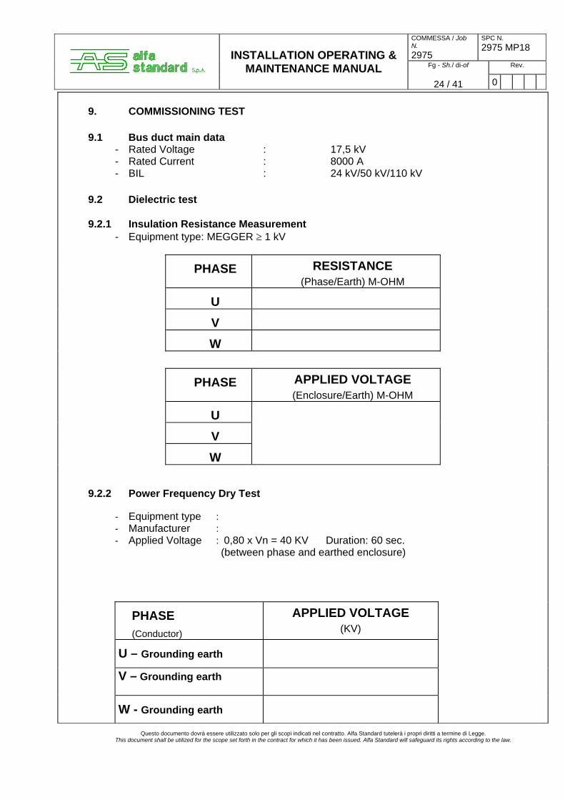
24 / 41 0
9. COMMISSIONING TEST 9.1 Bus duct main data - Rated Voltage : 17,5 kV - Rated Current : 8000 A - BIL : 24 kV/50 kV/110 kV 9.2 Dielectric test 9.2.1 Insulation Resistance Measurement - Equipment type: MEGGER ≥ 1 kV
PHASE RESISTANCE (Phase/Earth) M-OHM
U
V
W
PHASE APPLIED VOLTAGE (Enclosure/Earth) M-OHM
U
V
W
9.2.2 Power Frequency Dry Test - Equipment type : - Manufacturer :
- Applied Voltage : 0,80 x Vn = 40 KV Duration: 60 sec. (between phase and earthed enclosure)
PHASE (Conductor)
APPLIED VOLTAGE (KV)
U – Grounding earth
V – Grounding earth
W - Grounding earth
Questo documento dovrà essere utilizzato solo per gli scopi indicati nel contratto. Alfa Standard tutelerà i propri diritti a termine di Legge.
This document shall be utilized for the scope set forth in the contract for which it has been issued. Alfa Standard will safeguard its rights according to the law.

COMMESSA / Job N. 2975
SPC N. 2975 MP18
Fg - Sh./ di-of Rev.
INSTALLATION OPERATING & MAINTENANCE MANUAL
25 / 41 0
9.3 External inspection
Supporting structure - integrity - anchoring - galvanizing/painting - thermal expansion joints Bus duct enclosure - secured properly - properly isolated - wall plates/installed properly Grounding - assembly/connected to grid (in 1 point) Cubicles - integrity - anchoring - galvanizing/painting - ground connection
Emissione / Issue Rev Descrizione / Description Comp./Prep. ‘d Ver / Chk’d App. / Appr’d DATA
Questo documento dovrà essere utilizzato solo per gli scopi indicati nel contratto. Alfa Standard tutelerà i propri diritti a termine di Legge.
This document shall be utilized for the scope set forth in the contract for which it has been issued. Alfa Standard will safeguard its rights according to the law.
COMMESSA / Job N. 2975
SPC N. 2975 MP18
Fg - Sh./ di-of Rev.
INSTALLATION OPERATING & MAINTENANCE MANUAL
26 / 41 0
10. MAINTENANCE 10.1 Introduction At factory, before bus duct system packing and shipment, all the bus duct spools are cleaned inside and plugged at the extremity using a polyethylene sheet clamped on the bus duct enclosure. For this type of bus ducts is not required any maintenance, anyway we recommend to avoid as much as possible to open the inspection hatches (where applicable) and to dismantle the extremity. Cares are to be taken when it is recommended to dismantle the followings: - Current transformers - for maintenance and/or substitution - Links - for equipment isolation. The inspection hatches must be closed immediately after the operations in order to avoid massive dust entrance. In the event of disassembly and reassemble of any part of the conductor, it is recommended the use of dynamometric spanner to assure the torque setting on the bolts, as shown in the attached table. In the subsequent pages are briefly described the operations to disassemble and reassemble the major parts of the bus duct such as:
• Insulators • Enclosure flexible joint • Extremity – bushing • Bolted conductor connections
Before carrying out any operation it is suggested to review the relevant detailed drawings. If some components have to be substituted, its necessary to request Alfa Standard using the number position and, if exists, the reference. Example: If the insulator box cover has to be substituted, the requisition of spare part will shown the following: No. 12 cover item Pos. 4 code MP2.
Questo documento dovrà essere utilizzato solo per gli scopi indicati nel contratto. Alfa Standard tutelerà i propri diritti a termine di Legge.
This document shall be utilized for the scope set forth in the contract for which it has been issued. Alfa Standard will safeguard its rights according to the law.
COMMESSA / Job N. 2975
SPC N. 2975 MP18
Fg - Sh./ di-of Rev.
INSTALLATION OPERATING & MAINTENANCE MANUAL
27 / 41 0
10.2 Cyclic maintenance For this type of bus ducts is not required any maintenance, anyway we recommend to proceed, every 2 – 3 years making the most of the stop of the plant, with the following procedures: 1 - Control the tighten of the contacts (chapter 12). 2 - Check the status of the bushing insulator and the flexible joints. 3 - Check the efficiency of the earth connections. 4 - Control the treated surfaces (painted, silvery, ecc.) 5 - Control the integrity of the auxiliary elements (if supplied), (heating, condensate discharge, current transformers, ecc.) 6 - Check the insulation with eventually dielectric tests.
Questo documento dovrà essere utilizzato solo per gli scopi indicati nel contratto. Alfa Standard tutelerà i propri diritti a termine di Legge.
This document shall be utilized for the scope set forth in the contract for which it has been issued. Alfa Standard will safeguard its rights according to the law.

COMMESSA / Job N. 2975
SPC N. 2975 MP18
Fg - Sh./ di-of Rev.
INSTALLATION OPERATING & MAINTENANCE MANUAL
28 / 41 0
11 COMPONENTS
11.1 Insulator
POS. DESCRIPTION CODE MATERIAL
1 INSULATOR MP7 PORCELAIN
2 HEAD SHOCK ABSORBER MP-19 NEOPRENE
3 SEAL MP-34 NEOPRENE
4 COVER MP-2 G-Al-Si.9-Mn-Mg
5 GROWER WASHER M6 STAINLESS STEEL
6 BOLT M6X25 STAINLESS STEEL
7 NUT M6 STAINLESS STEEL
Questo documento dovrà essere utilizzato solo per gli scopi indicati nel contratto. Alfa Standard tutelerà i propri diritti a termine di Legge.
This document shall be utilized for the scope set forth in the contract for which it has been issued. Alfa Standard will safeguard its rights according to the law.
2
1
7
3
4
65
INSULATOR SUPPORT (weld to the conductor)
COMMESSA / Job N. 2975
SPC N. 2975 MP18
Fg - Sh./ di-of Rev.
INSTALLATION OPERATING & MAINTENANCE MANUAL
29 / 41 0
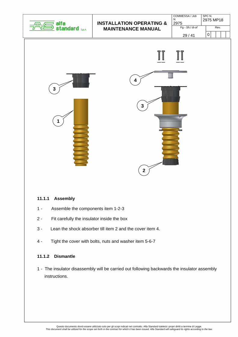
11.1.1 Assembly 1 - Assemble the components item 1-2-3 2 - Fit carefully the insulator inside the box 3 - Lean the shock absorber till item 2 and the cover item 4.
4 - Tight the cover with bolts, nuts and washer item 5-6-7
11.1.2 Dismantle
1 - The insulator disassembly will be carried out following backwards the insulator assembly
instructions.
Questo documento dovrà essere utilizzato solo per gli scopi indicati nel contratto. Alfa Standard tutelerà i propri diritti a termine di Legge.
This document shall be utilized for the scope set forth in the contract for which it has been issued. Alfa Standard will safeguard its rights according to the law.
1
3
3
2
4

COMMESSA / Job N. 2975
SPC N. 2975 MP18
Fg - Sh./ di-of Rev.
INSTALLATION OPERATING & MAINTENANCE MANUAL
30 / 41 0
11.2 Flexible joint
POS. DESCRIPTION CODE/DIMENSION MATERIAL
1 FLEXIBLE JOINT / NEOPRENE
2 BAND IRON + CLIP 19 x 0,76 STAINLESS STEEL
3 BAND IRON L=100 mm 19 x 0,76 STAINLESS STEEL
4 PROTECTION SP. 3 mm ALUMINIUM
5 SHORT CIRCUIT SHUNT SP. 4/8 mm ALUMINIUM
6 SEAL / SILICONE
Questo documento dovrà essere utilizzato solo per gli scopi indicati nel contratto. Alfa Standard tutelerà i propri diritti a termine di Legge.
This document shall be utilized for the scope set forth in the contract for which it has been issued. Alfa Standard will safeguard its rights according to the law.
COMMESSA / Job N. 2975
SPC N. 2975 MP18
Fg - Sh./ di-of Rev.
INSTALLATION OPERATING & MAINTENANCE MANUAL
31 / 41 0
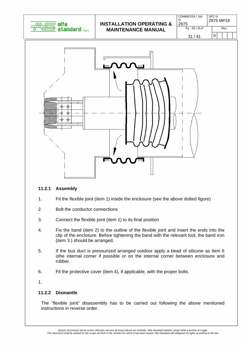
11.2.1 Assembly 1. Fit the flexible joint (item 1) inside the enclosure (see the above dotted figure) 2. Bolt the conductor connections 3. Connect the flexible joint (item 1) to its final position 4. Fix the band (item 2) to the outline of the flexible joint and insert the ends into the
clip of the enclosure. Before tightening the band with the relevant tool, the band iron (item 3 ) should be arranged.
5. If the bus duct is pressurized arranged outdoor apply a bead of silicone as item 6
othe internal corner if possible or on the internal corner between enclosure and rubber.
6. Fit the protective cover (item 4), if applicable, with the proper bolts. 1. 11.2.2 Dismantle
The “flexible joint” disassembly has to be carried out following the above mentioned instructions in reverse order.
Questo documento dovrà essere utilizzato solo per gli scopi indicati nel contratto. Alfa Standard tutelerà i propri diritti a termine di Legge.
This document shall be utilized for the scope set forth in the contract for which it has been issued. Alfa Standard will safeguard its rights according to the law.

COMMESSA / Job N. 2975
SPC N. 2975 MP18
Fg - Sh./ di-of Rev.
INSTALLATION OPERATING & MAINTENANCE MANUAL
32 / 41 0
11.3 Bushing insulator
POS. DESCRIZIONE CODICE
DIMENSIONE MATERIALE
1 END BUSHING CX 531 SILICONE
2 FLANGE Sp.=5 mm ALUMINIUM
3 SHUNT Sp.= 4/8 mm ALUMINIUM
4 BOLT M8 x 35 STAINLESS STEEL
5 PLAIN WASHER M8 STAINLESS STEEL
6 GROWER WASHER M8 STAINLESS STEEL
7 NUT M8 STAINLESS STEEL
8 BAND IRON + CLIP 19x0,76 STAINLESS STEEL
9 SEAL / SILICONE
10 BAND IRON L=100 mm 19 x 0,76 STAINLESS STEEL
Questo documento dovrà essere utilizzato solo per gli scopi indicati nel contratto. Alfa Standard tutelerà i propri diritti a termine di Legge.
This document shall be utilized for the scope set forth in the contract for which it has been issued. Alfa Standard will safeguard its rights according to the law.
REMOVE AFTER ASSEMBLY

COMMESSA / Job N. 2975
SPC N. 2975 MP18
Fg - Sh./ di-of Rev.
INSTALLATION OPERATING & MAINTENANCE MANUAL
33 / 41 0
11.3.1 Assembly NOTE: To avoid breakage of end silicone bushing during installation, we recommend to protect the extremities of conductor plates with aluminium sleeve (A) greasy with Vaseline. 1. If required, apply the gasket (item 1) on the bus duct shunt (item 3). 2. Fit the end bushing (item 1) on the conductor, laying the flange on the shunt and check
that the location is in accordance with the relevant drawing. 3. Place the flange (item 2) holes in correspondence to the shunt holes and after having
temporary clamped the flange, drill the end bushing flange holes. 4. Bolt with bolts, washers and nuts (item 4, 5, 6 &7). 5. If necessary, trim the bushings with protrudes from the enclosure flange. 6. Fix the band iron (item 8) with the clip, before tightening the band with the relevant tool,
the equipotential connection should be arranged (item 10), see detail “A-A” of paragraph 9.3.
7. If the bus duct is pressurized apply a bead of silicone (item 9) along all the perimeter,
of neoprene end bushing. 8. Bolt the conductor connections. 11.3.2 Dismantle
1. To dismantle the end bushing, follow the above mentioned instructions in reverse order.
Questo documento dovrà essere utilizzato solo per gli scopi indicati nel contratto. Alfa Standard tutelerà i propri diritti a termine di Legge.
This document shall be utilized for the scope set forth in the contract for which it has been issued. Alfa Standard will safeguard its rights according to the law.
COMMESSA / Job N. 2975
SPC N. 2975 MP18
Fg - Sh./ di-of Rev.
INSTALLATION OPERATING & MAINTENANCE MANUAL
34 / 41 0
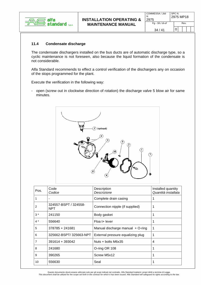
11.4 Condensate discharge The condensate dischargers installed on the bus ducts are of automatic discharge type, so a cyclic maintenance is not foreseen, also because the liquid formation of the condensate is not considerable. Alfa Standard recommends to effect a control verification of the dischargers any on occasion of the stops programmed for the plant. Execute the verification in the following way: - open (screw out in clockwise direction of rotation) the discharge valve 5 blow air for same
minutes.
Pos. Code Codice
Description Descrizione
Installed quantity Quantità installata
1 - Complete drain casing 1
2 324557-BSPT / 324558-NPT Connection nipple (if supplied) 1
3 * 241150 Body gasket 1
4 * 556640 Floa t+ lever 1
5 378785 + 241681 Manual discharge manual + O-ring 1
6 325662-BSPT/ 325663-NPT External pressure equalizing plug 1
7 391614 + 393042 Nuts + bolts M6x35 4
8 241680 O-ring OR 108 1
9 390265 Screw M5x12 1
10 556630 Seal 1
Questo documento dovrà essere utilizzato solo per gli scopi indicati nel contratto. Alfa Standard tutelerà i propri diritti a termine di Legge. This document shall be utilized for the scope set forth in the contract for which it has been issued. Alfa Standard will safeguard its rights according to the law.

COMMESSA / Job N. 2975
SPC N. 2975 MP18
Fg - Sh./ di-of Rev.
INSTALLATION OPERATING & MAINTENANCE MANUAL
35 / 41 0
11.5 Instruction for the application of seal on inspection doors and flanges Bus ducts are supplied without gasket on inspection doors and flanges. To apply follow the instructions below.
1) Apply a final strip of gasket along the edge with an overlap on corner (as in fig. 1) for
inspection doors and rectangular flanges or with a little overlap (as in fig. 2) for circular flanges.
2) Drill the seal in correspondence with holes with a punch or graver. 3) Position and screw the panels.
Questo documento dovrà essere utilizzato solo per gli scopi indicati nel contratto. Alfa Standard tutelerà i propri diritti a termine di Legge.
This document shall be utilized for the scope set forth in the contract for which it has been issued. Alfa Standard will safeguard its rights according to the law.
OVERLAP
OVERLAP
20÷30mm
FIG.1
FIG.2

COMMESSA / Job N. 2975
SPC N. 2975 MP18
Fg - Sh./ di-of Rev.
INSTALLATION OPERATING & MAINTENANCE MANUAL
36 / 41 0
12 CONTACTS COAXIAL AND STANDARD BUS BAR CONTACT ASSEMBLY WITH NON
MAGNETIC STAINLESS STEEL BOLTS 1. Clean contact surfaces with a soft non-metallic brush or a cloth soaked in solvent 2. Spread neutral Vaseline on contact 3. If surfaces are copper tinned or made of aluminium, clean the contact surfaces with a
soft wire brush and Vaseline to obtain a shiny surface (to remove Al-oxide film), then protect this with Vaseline.
4. Assembly bolt, washers and nuts as indicated in the drawing below. Before assembling
it is very important to grease bolts, washers and nuts with Vaseline.
5. Tighten each bolt with a dynamometric spanner with a driving torque setting of A daN x m (see table)
6. Check that this driving torque is suitable for all bolts; then tighten each bolt with a driving
torque setting of B daN x m (see table) 7. Pal lock nut must be screwed manually until it fits against the nut and then with a
spanner from 1/4 to 1/3 turn. 8. Remove excess Vaseline with a cloth.
Ø of Bolt mm 10 12 14 16
A driving torque daN.m 2 3,5 6 8
B driving torque daNm 3 5 8 12
Questo documento dovrà essere utilizzato solo per gli scopi indicati nel contratto. Alfa Standard tutelerà i propri diritti a termine di Legge. This document shall be utilized for the scope set forth in the contract for which it has been issued. Alfa Standard will safeguard its rights according to the law.

COMMESSA / Job N. 2975
SPC N. 2975 MP18
Fg - Sh./ di-of Rev.
INSTALLATION OPERATING & MAINTENANCE MANUAL
37 / 41 0
13. PRESSURIZATION 13.1 Introduction Given that: - the pressurization represents the second level of bus duct inner part protection from the
external ambient and atmosphere; - the first bus duct protection level is constituted by a series of condensate dischargers
which discharge outside all the condensate that can appear inside the same bus ducts, as consequence of air entry from outside up to ambient thermal range.
the condensate dischargers are a standard complement of bus ducts and so are always
present, also when the pressurization system is realized; - the first bus duct protection level grants the full operative efficiency of bus ducts, even if it
is not able to avoid the entry of polluting / corrosive agents in them, or also the entry of dust eventually present in the atmosphere;
- the pressurization, providing to put inside the bus ducts air previously dehydrated and
keeping it in conditions of a light overpressure, realizes a barrier against the entry of ambient air, avoiding in this case the inconveniences cause by ambient air.
13.2 Equipment - A pressurization system is dedicated to every unit of a plant, consisting of 3 single-phase
bus ducts, it is able to supply a minimum of 1.5 times the amount of air needed to restore theoretical maximum physiological leakage in a unit;
- Every pressurization system consists of a pressurization panel and the relevant material
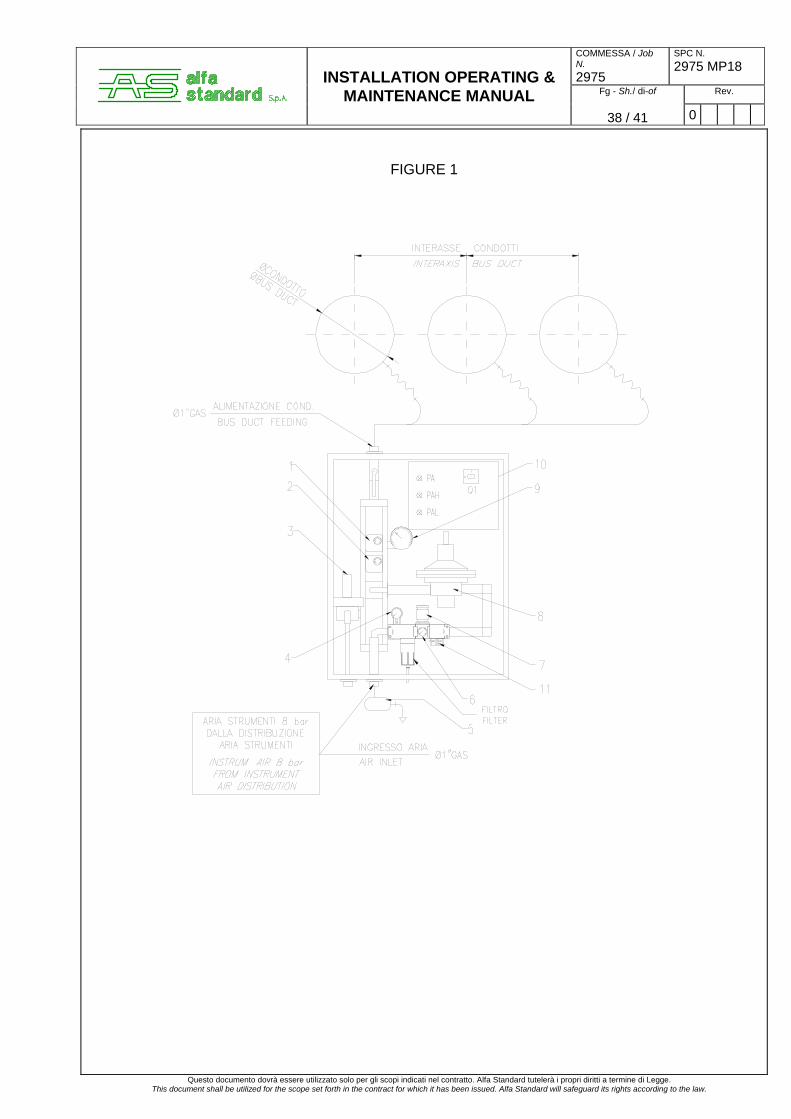
necessary for realizing bus duct connection. - The pressurization panel is made up of the following components (see Fig. 1):
1) Pressure switch for high pressure; 2) Pressure switch for low pressure; 3) Relief valve; 4) Manometer – air feeding pressure; 5) Automatic condensate discharge; 6) Manometer – pressure 1st reduction step; 7) Pressure reducing valve - 1st reduction step; 8) Pressure reducing valve – 2nd reduction step; 9) Manometer – bus duct pressure; 10) Electric panel for signals interfacing. PA electric feeding present PAH bus duct high pressure alarm light PAL bus duct low pressure alarm light Q1 line disconnecting switch 11) Exit for quick IPB pressurization
Questo documento dovrà essere utilizzato solo per gli scopi indicati nel contratto. Alfa Standard tutelerà i propri diritti a termine di Legge.
This document shall be utilized for the scope set forth in the contract for which it has been issued. Alfa Standard will safeguard its rights according to the law.
COMMESSA / Job N. 2975
SPC N. 2975 MP18
Fg - Sh./ di-of Rev.
INSTALLATION OPERATING & MAINTENANCE MANUAL
38 / 41 0
FIGURE 1
Questo documento dovrà essere utilizzato solo per gli scopi indicati nel contratto. Alfa Standard tutelerà i propri diritti a termine di Legge. This document shall be utilized for the scope set forth in the contract for which it has been issued. Alfa Standard will safeguard its rights according to the law.

COMMESSA / Job N. 2975
SPC N. 2975 MP18
Fg - Sh./ di-of Rev.
INSTALLATION OPERATING & MAINTENANCE MANUAL
39 / 41 0
13.3 Operations Each pressurization system acts as follows:
- the pressurization panel receives the air at a pressure of 4-7 BAR, that is read on the manometer in position 4. Passing through the filter and the 1st reduction stage it is cleaned and reduced at 1,7 bar (group in position 7), on the manometer in position 6the pressure of the air exit after the first reduction step is visible.
- The air will arrive in the second reduction group (position 8). At the exit of the same, the pressure of the fluid will be reduced to the foreseen value to be put inside the conductors 5mbar.
- The value read on the manometer in position 9 is the pressure obtained directly on the exit of reducing valve in position 8 and it’s the same of IPB pressure.
The ensemble of assembled equipments can grant that to the bus ducts doesn’t arrive a pressure superior to the maximum foreseen, even in the event of a simultaneous damage of the two pressure reducing valves. - Once the pressurization system is activated following the procedures listed below, and
reached the balance conditions, three following cases can be supposed: CASE A: Pressurization system activated/efficient instruments The leaks occurred in the bus ducts remain into the foreseen limits, the system is in balance at a pressurization of 5 mbar and any signalling/safety device is activated. CASE B: Pressurization system activated/efficient instruments /bus ducts with seal
anomalies The leaks occurred in the bus ducts up to anomalies, exceed also the limits of pressurization panel restoring, the pressure inside bus ducts decreases, and when it reach the value of 2,5 mbar the pressure switch for low pressure starts (pos. 2). The anomaly is signalled on the pressurization panel by the light PAL and eventually in the control room so that the operator can take the necessary actions. CASE C: Pressurization system activated/instruments with anomalies occurred Possible causes are: - Breaking of pressure reducer - 1st reduction step in position 7 The air doesn’t pass, the fluid doesn’t arrive to the conductors and the pressure switch in
pos. 2 signals low pressure alarm (PAL light on), on manometers in pos. 9 there is no reading.
- The air passes at the conductors with a pressure superior to 8mbar given by the reducing valve in pos. 8, the pressure switch in pos. 1 signals high pressure alarm (PAH light on) and the relief valve (pos. 3) acts discharging the exceeding pressure.
- In the over mentioned case, check the correct adjustment of reducing valve in pos. 8 regulating it again at the work pressure (5mbar)
Questo documento dovrà essere utilizzato solo per gli scopi indicati nel contratto. Alfa Standard tutelerà i propri diritti a termine di Legge. This document shall be utilized for the scope set forth in the contract for which it has been issued. Alfa Standard will safeguard its rights according to the law.
COMMESSA / Job N. 2975
SPC N. 2975 MP18
Fg - Sh./ di-of Rev.
INSTALLATION OPERATING & MAINTENANCE MANUAL
40 / 41 0
13.4 Procedure for setting up the pressurization system Starting from the completion of the plant inspection (*), functionally and mechanically, carry out the following steps: - Verify that the two interception valves placed under the first reduction stage (pos. 7)are
closed - Operate the manometer (pos. 4, 9) opening the manual interception valve near to the
same - Check that no obstacles are present for the use of the relief valve (pos. 3) - Ask the operator of control room to activate the electric circuits of feed and signalling
relevant to the pressurization panel. As a consequence the low pressure signals (PAL light) in the bus ducts result activated both on the panel and in the control room.
- Gradually open the interception manual valve of air feeding of pressurization panel,
keeping closed the air interception manual valve at bus ducts. - Regulate the first reduction stage acting directly on the reducing valve grip in pos. 7 and
take the exit pressure at 1,7 bar read on manometer in pos. 6. - Regulate the second reduction stage acting directly on the reducing valve in pos. 8 and
take the exit pressure at 5mbar read on the manometer in pos. 9 Gradually open the manual valve of bus duct air interception. When the pressure in the bus ducts reaches 2,5 mbar, the low pressure signalling lamp (PAL) turns off on the panel and in the control room the anomaly signal is lost. The pressure inside the bus ducts continues gradually to increase till stabilize at the foreseen value of 5 mbar. - The procedure of starting/setting is completed.
(*) The pressurization panel supplied by Alfa Standard will reach the site already tested/inspected and regulated for the running following the optimal operating pressure (5 mbar)
Questo documento dovrà essere utilizzato solo per gli scopi indicati nel contratto. Alfa Standard tutelerà i propri diritti a termine di Legge. This document shall be utilized for the scope set forth in the contract for which it has been issued. Alfa Standard will safeguard its rights according to the law.

COMMESSA / Job N. 2975
SPC N. 2975 MP18
Fg - Sh./ di-of Rev.
INSTALLATION OPERATING & MAINTENANCE MANUAL
41 / 41 0
13.5 Quick duct pressurization If the Committee intends to carry out a quick bus duct pressurization it is necessary to predispose the relevant circuit. 1. Correctly carry out the starting procedure 2. Close the manual valve of bus duct air interception 3. Regulate the second reduction stage acting directly on the reducing valve in pos. 8 and
take the exit pressure at a value included between 15 and 20mbar maximum (pressure read on the manometer in pos. 9)
4. Gradually open the manual valve of bus duct air interception 5. It is obliged for the technical personnel who carry out this operation, to constantly check
the bus duct loading 6. When the technical personnel who carry out this operation verify that the pressure read
on the manometer in pos. 9 is close to the work pressure (5mbar) or exceed it, must immediately close the manual valve of bus duct air interception
7. Regulate again the second reduction stage acting directly on the reducing valve in pos. 8 and take the exit pressure at 5mbar read on the manometer in pos. 9
8. Gradually open the manual valve of bus duct air interception 9. The procedure of rapid starting/setting is completed. 10. The conductor pressure could be superior to 8mbar, the pressure switch in pos. 1 signs
high pressure alarm (PAH light on) and the relief valve (pos. 3) acts discharging the excess pressure.
Bus ducts pressure continues gradually to equilibrate till stabilize to the foreseen value of 5mbar. NOTES 1. in order to check the eventual leaks on the bus duct, it is necessary to use a nebulizer
containing water and soap. If such leaks are discovered, they must be plugged. 2. Never exceed the pressure of 20 mbar otherwise Alfa Standard will not be responsible in
case of manometers, bushing and coupling breaking present on the bus duct, and interested by air pressure.
Questo documento dovrà essere utilizzato solo per gli scopi indicati nel contratto. Alfa Standard tutelerà i propri diritti a termine di Legge. This document shall be utilized for the scope set forth in the contract for which it has been issued. Alfa Standard will safeguard its rights according to the law.