Embed Size (px)
Citation preview
The product images in the whole catalog are marked in color for visual purpose only but do not represent the actual product.
NEW
ACEolatorIsolates Vibration
Vibration Technology
Issue: July 2013
Automation Control Equipment
Issu
e Ju
ly 2
013
– Th
e pr
oduc
t im
ages
in th
e wh
ole
cata
log
are
mar
ked
in c
olor
for v
isua
l pur
pose
onl
y bu
t do
not r
epre
sent
the
actu
al p
rodu
ct.
Issu
e Ju
ly 2
013
The ACE Story
In the 1950’s industrial shock absorbers were custom designed for specific weights, velocity and propelling force
of the moving load. If these variables were precisely known and constant over time, a fixed orifice shock absorber,
called a “hydroshock,” did the job. But most often the weight, speed and forces were usually estimates and
designing and building a shock that would work was a trial and error process.
The founder of ACE Controls, William J. Chorkey Sr. was an engineer at MAC Valves where he was asked by Ford
Motor Co. to design circuits to decelerate air cylinders. He and Walter Ludwig, the President of MAC Valves,
devised a valve circuit that reversed the direction of the cylinder piston cylinder before the end-of-stroke impact.
Although this circuit was not an ideal solution, Ford benefited by increased production and less damage to air
cylinders. Mr. Chorkey recognized that there was need for deceleration technology in order to increase production
speeds.
Mr. Chorkey started Automation Control Equipment Company, later changed to ACE Controls, in 1963 as a
pneumatic accessories manufacturer. Their first products were flow controls and check valves. Since Mr. Chorkey
knew most of the MAC Valves distributors, he signed many of them up as distributors.
Lynn Nagle, of Kober Sales, Flint, MI, was the very first ACE first distributor. Lynn took Mr. Chorkey on a sales call
at GM’s Fisher Body where they were having problems with a non-adjustable hydroshock on a bumper line. When
Fisher Body tried to speed up production, bumpers flew off the line. Mr. Chorkey studied the hydroshock concept
and then designed a way to adjust a shock in the field. “Adjust-A-Shock” was born and ACE was on its way.
50 Years later, ACE is well recognized as the global leader in industrial shock isolation technology with a strong
belief in local support, available worldwide.
ACE Controls apply deceleration and vibration dampening expertise to diverse applications that range from the
bottom of the ocean to satellites in space. We support our customers with a worldwide ISO organization, strong
investments in new technologies and sophisticated sizing software. Our technologies include: ACEolator vibration
and sound absorption solutions, industrial shock absorbers, safety shock absorbers, LOCKED clamping elements,
TUBUS profile dampers, rotary dampers, hydraulic dampers and feed controls, and industrial gas springs.
Today we partner with over 120 engineering-focused distributors who are located in over 45 different countries,
ACE is available to help you, wherever you are.
ACE Controls Inc. . 23435 Industrial Park Dr., Farmington Hills . Michigan 48335 . T +1 (800) 521-3320 . F +1 (248) 476-2470 . [email protected] . www.acecontrols.com
Automation Control Equipment2
2
Issu
e Ju
ly 2
013
– Th
e pr
oduc
t im
ages
in th
e wh
ole
cata
log
are
mar
ked
in c
olor
for v
isua
l pur
pose
onl
y bu
t do
not r
epre
sent
the
actu
al p
rodu
ct.
ACE is the internationally recognized expert in the field of industrial damping technology – with representative offices in 45 countries on all continents. ACE is headquartered in Farmington Hills, MI since 1963.
ACE is your source for industrial damping technology
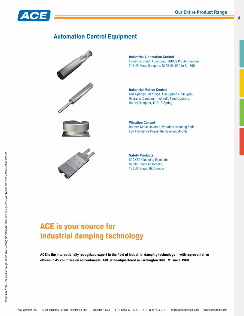
Safety Products LOCKED Clamping Elements, Safety Shock Absorbers, TUBUS Single Hit Damper
Vibration Control Rubber-Metal Isolators, Vibration-Isolating Pads, Low Frequency Pneumatic Leveling Mounts
Industrial Motion Control Gas Springs Push Type, Gas Springs Pull Type, Hydraulic Dampers, Hydraulic Feed Controls, Rotary Dampers, TUBUS Spring
Industrial Automation Control Industrial Shock Absorbers, TUBUS Profile Dampers, TUBUS Press Dampers, SLAB SL-030 to SL-300
Automation Control Equipment
ACE Controls Inc. . 23435 Industrial Park Dr., Farmington Hills . Michigan 48335 . T +1 (800) 521-3320 . F +1 (248) 476-2470 . [email protected] . www.acecontrols.com
Our Entire Product Range3
Vibration isolation 6
Overview of products and applications 10
How to use diagrams 12
01 - Rubber-Metal Isolators 14
02 - Vibration-Isolating Pads 44
03 - Low Frequency Pneumatic Leveling Mounts 54
Notes 64
Calculation sheet 65
Contents
General
Contents4
4
Issu
e Ju
ly 2
013
– Th
e pr
oduc
t im
ages
in th
e wh
ole
cata
log
are
mar
ked
in c
olor
for v
isua
l pur
pose
onl
y bu
t do
not r
epre
sent
the
actu
al p
rodu
ct.
Rubber-Metal Isolators01
03
02
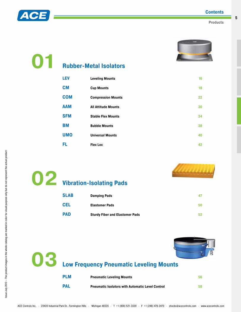
LEV Leveling Mounts 16
CM Cup Mounts 18
COM Compression Mounts 22
AAM All Attitude Mounts 30
SFM Stable Flex Mounts 34
BM Bubble Mounts 38
UMO Universal Mounts 40
FL Flex Loc 42
SLAB Damping Pads 47
CEL Elastomer Pads 50
PAD Sturdy Fiber and Elastomer Pads 52
Vibration-Isolating Pads
Low Frequency Pneumatic Leveling Mounts
PLM Pneumatic Leveling Mounts 56
PAL Pneumatic Isolators with Automatic Level Control 58
ACE Controls Inc. . 23435 Industrial Park Dr., Farmington Hills . Michigan 48335 . T +1 (800) 521-3320 . F +1 (248) 476-2470 . [email protected] . www.acecontrols.com
Products
Contents5
Issu
e Ju
ly 2
013
F1
F2t
+a
-a
0
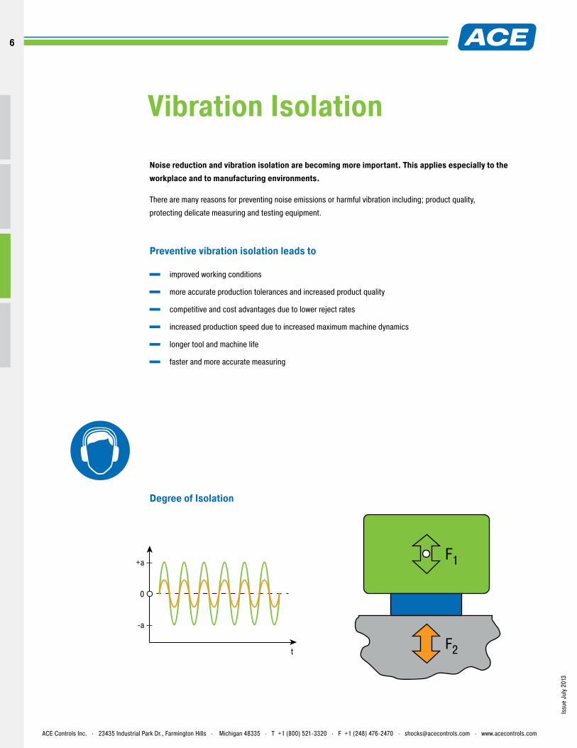
Degree of Isolation
Vibration Isolation
Noise reduction and vibration isolation are becoming more important. This applies especially to the workplace and to manufacturing environments.
There are many reasons for preventing noise emissions or harmful vibration including; product quality,
protecting delicate measuring and testing equipment.
Preventive vibration isolation leads to
improved working conditions
more accurate production tolerances and increased product quality
competitive and cost advantages due to lower reject rates
increased production speed due to increased maximum machine dynamics
longer tool and machine life
faster and more accurate measuring
ACE Controls Inc. . 23435 Industrial Park Dr., Farmington Hills . Michigan 48335 . T +1 (800) 521-3320 . F +1 (248) 476-2470 . [email protected] . www.acecontrols.com
6
6
Issu
e Ju
ly 2
013
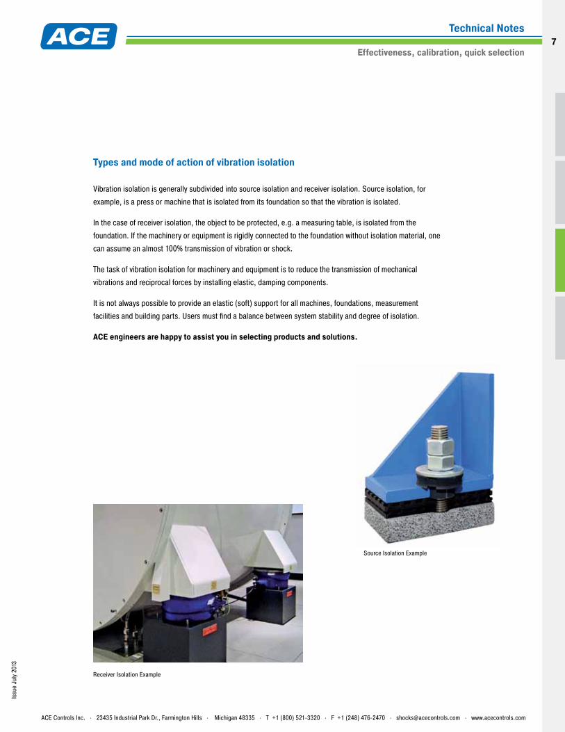
Source Isolation Example
Receiver Isolation Example
Types and mode of action of vibration isolation
Vibration isolation is generally subdivided into source isolation and receiver isolation. Source isolation, for
example, is a press or machine that is isolated from its foundation so that the vibration is isolated.
In the case of receiver isolation, the object to be protected, e.g. a measuring table, is isolated from the
foundation. If the machinery or equipment is rigidly connected to the foundation without isolation material, one
can assume an almost 100% transmission of vibration or shock.
The task of vibration isolation for machinery and equipment is to reduce the transmission of mechanical
vibrations and reciprocal forces by installing elastic, damping components.
It is not always possible to provide an elastic (soft) support for all machines, foundations, measurement
facilities and building parts. Users must find a balance between system stability and degree of isolation.
ACE engineers are happy to assist you in selecting products and solutions.
ACE Controls Inc. . 23435 Industrial Park Dr., Farmington Hills . Michigan 48335 . T +1 (800) 521-3320 . F +1 (248) 476-2470 . [email protected] . www.acecontrols.com
Technical Notes
Effectiveness, calibration, quick selection7
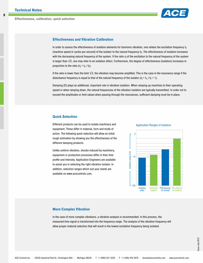
2
10
100
Isol
atio
n ra
nge
in H
z
PAL pneuma-tic isolators
PLM pneuma-tic mounts
Elastomersupport
Isolatingplate
Issu
e Ju
ly 2
013
Effectiveness and Vibration Calibration
In order to assess the effectiveness of isolation elements for harmonic vibration, one relates the excitation frequency fe
(machine speed in cycles per second) of the isolator to the natural frequency f0. The effectiveness of isolation increases
with the decreasing natural frequency of the system. If the ratio ɳ of the excitation to the natural frequency of the system
is larger than √2, one may refer to an isolation effect. Furthermore, the degree of effectiveness (isolation) increases in
proportion to the ratio (ɳ = fe / f0).
If the ratio is lower than the limit √2, the vibration may become amplified. This is the case in the resonance range if the
disturbance frequency is equal to that of the natural frequency of the isolator (ɳ = fe / f0 = 1).
Damping (D) plays an additional, important role in vibration isolation. When ramping up machines to their operating
speed or when ramping down, the natural frequencies of the vibration isolation are typically transmitted. In order not to
exceed the amplitudes or limit values when passing through the resonances, sufficient damping must be in place.
More Complex Vibration
In the case of more complex vibrations, a vibration analysis is recommended. In this process, the
measured time signal is transformed into the frequency range. The analysis of the vibration frequency will
allow proper material selection that will result in the lowest excitation frequency being isolated.
Quick Selection
Different products can be used to isolate machinery and
equipment. These differ in material, form and mode of
action. The following quick selection will allow an initial
rough estimation by showing you the effectiveness of the
different damping products.
Unlike uniform vibration, shocks induced by machinery,
equipment or production processes differ in their time
profile and intensity. Application Engineers are available
to assist you in selecting the right vibration isolator. In
addition, selection ranges which suit your needs are
available on www.acecontrols.com.
Application Ranges of Isolators
ACE Controls Inc. . 23435 Industrial Park Dr., Farmington Hills . Michigan 48335 . T +1 (800) 521-3320 . F +1 (248) 476-2470 . [email protected] . www.acecontrols.com
Effectiveness, calibration, quick selection
Technical Notes8
8
100
10
2
100
10
11 10 60
Exci
tatio
n fre
quen
cy (H
z)
Isol
atio
n ra
nge
Natural frequency (Hz)
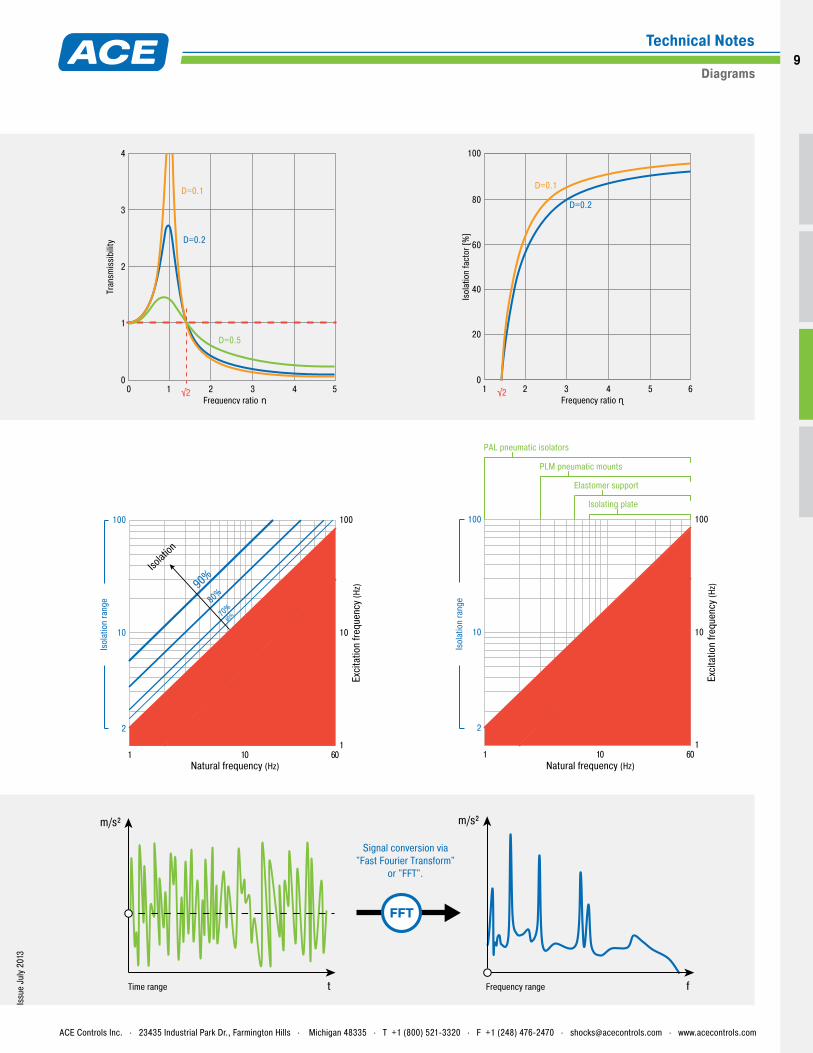
Resonance transmissibilit
y
Isolat
ion
90%
80%
70%60%
Trans
fer 1:1
100
10
11 10 60
Exci
tatio
n fre
quen
cy (H
z)
Natural frequency (Hz)
Resonance transmissibilit
y
Trans
fer 1:1
100
10
2
Isol
atio
n ra
nge
PAL pneumatic isolators
PLM pneumatic mounts
Elastomer support
Isolating plate
tTime range Frequency range
Signal conversion via"Fast Fourier Transform"
or "FFT".
m/s² m/s²
f
FFT
100
80
0
20
40
60
1 2 4 53 6
Isol
atio
n fa
ctor
[%]
Frequency ratio
D=0.1
D=0.2
ɳ√2
4
3
0
1
2
0 1 3 42 5
Tran
smis
sibi
lity
Frequency ratio
D=0.1
D=0.2
ɳ
D=0.5
√2
Issu
e Ju
ly 2
013
ACE Controls Inc. . 23435 Industrial Park Dr., Farmington Hills . Michigan 48335 . T +1 (800) 521-3320 . F +1 (248) 476-2470 . [email protected] . www.acecontrols.com
Diagrams
Technical Notes9
Issu
e Ju
ly 2
013
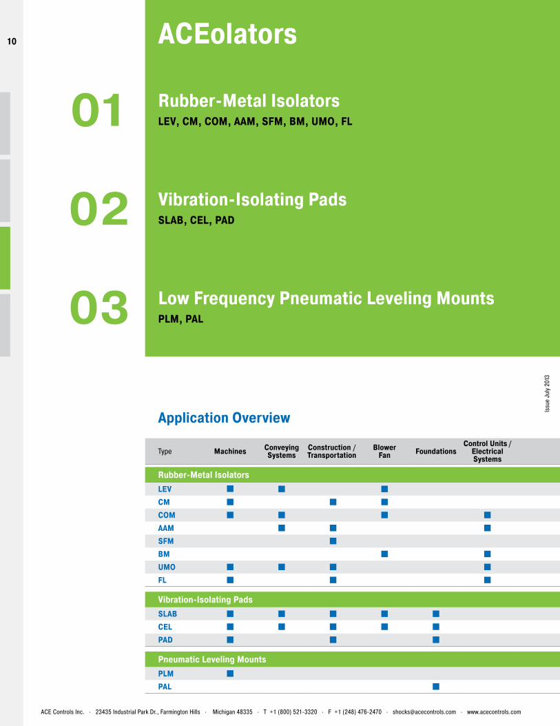
Rubber-Metal IsolatorsLEV, CM, COM, AAM, SFM, BM, UMO, FL01
Vibration-Isolating PadsSLAB, CEL, PAD02
Low Frequency Pneumatic Leveling MountsPLM, PAL03
Application Overview
ACEolators
ACE Controls Inc. . 23435 Industrial Park Dr., Farmington Hills . Michigan 48335 . T +1 (800) 521-3320 . F +1 (248) 476-2470 . [email protected] . www.acecontrols.com
Type Machines Conveying Systems
Construction / Transportation
BlowerFan Foundations
Control Units / Electrical Systems
Off-road EnginesGenerators Compressors Oil and
gas industry Aerospace Presses Medicine Measuring tables
Test benches Type
Rubber-Metal Isolators Rubber-Metal IsolatorsLEV LEVCM CMCOM COMAAM AAMSFM SFMBM BMUMO UMOFL FL
Vibration-Isolating Pads Vibration-Isolating PadsSLAB SLABCEL CELPAD PAD
Pneumatic Leveling Mounts Pneumatic Leveling MountsPLM PLMPAL PAL
10
10
Issu
e Ju
ly 2
013
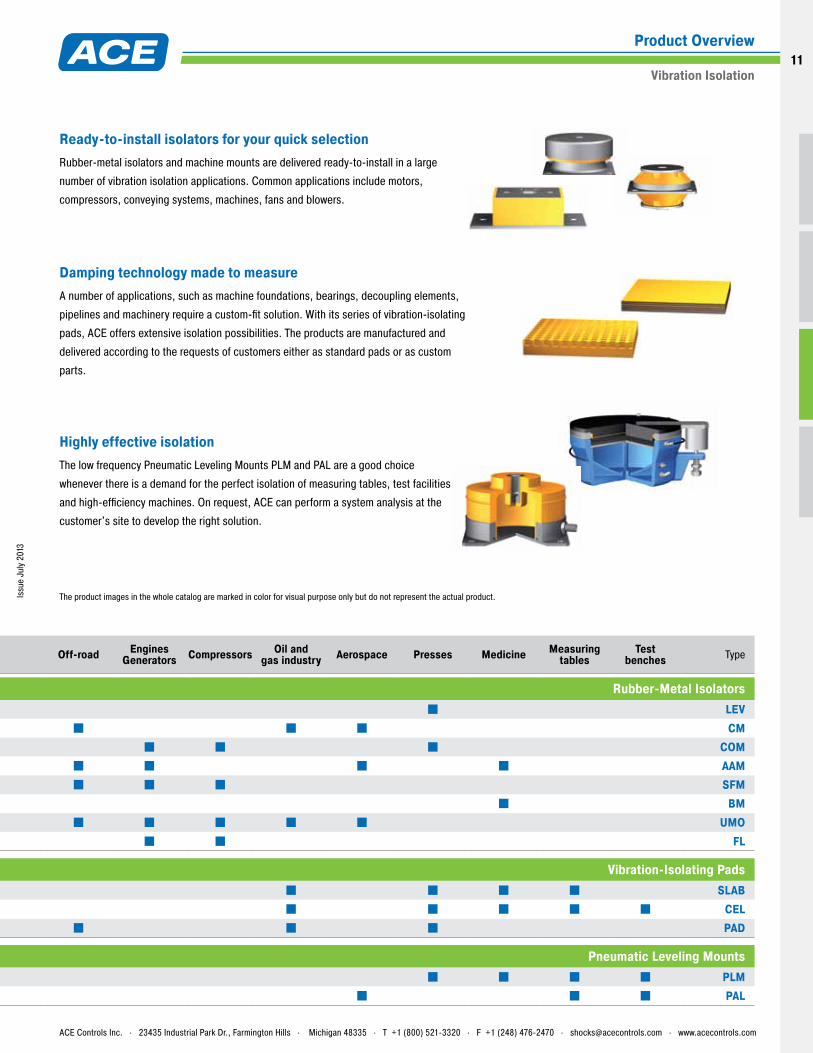
Ready-to-install isolators for your quick selectionRubber-metal isolators and machine mounts are delivered ready-to-install in a large
number of vibration isolation applications. Common applications include motors,
compressors, conveying systems, machines, fans and blowers.
Damping technology made to measureA number of applications, such as machine foundations, bearings, decoupling elements,
pipelines and machinery require a custom-fit solution. With its series of vibration-isolating
pads, ACE offers extensive isolation possibilities. The products are manufactured and
delivered according to the requests of customers either as standard pads or as custom
parts.
Highly effective isolationThe low frequency Pneumatic Leveling Mounts PLM and PAL are a good choice
whenever there is a demand for the perfect isolation of measuring tables, test facilities
and high-efficiency machines. On request, ACE can perform a system analysis at the
customer's site to develop the right solution.
ACE Controls Inc. . 23435 Industrial Park Dr., Farmington Hills . Michigan 48335 . T +1 (800) 521-3320 . F +1 (248) 476-2470 . [email protected] . www.acecontrols.com
Vibration Isolation
Product Overview
Type Machines Conveying Systems
Construction / Transportation
BlowerFan Foundations
Control Units / Electrical Systems
Off-road EnginesGenerators Compressors Oil and
gas industry Aerospace Presses Medicine Measuring tables
Test benches Type
Rubber-Metal Isolators Rubber-Metal IsolatorsLEV LEVCM CMCOM COMAAM AAMSFM SFMBM BMUMO UMOFL FL
Vibration-Isolating Pads Vibration-Isolating PadsSLAB SLABCEL CELPAD PAD
Pneumatic Leveling Mounts Pneumatic Leveling MountsPLM PLMPAL PAL
The product images in the whole catalog are marked in color for visual purpose only but do not represent the actual product.
11
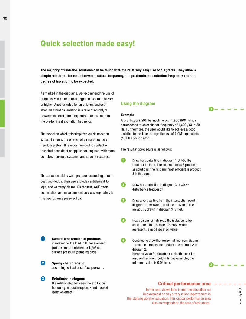
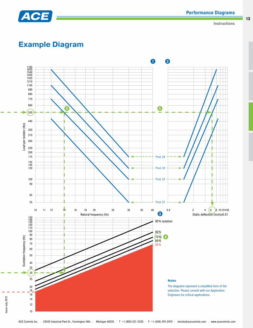
Critical performance areaIn the area shown here in red, there is either no
improvement or only a very minor improvement in the starting vibration situation. This critical performance area
also corresponds to the area of resonance.
2
1
Issu
e Ju
ly 2
013
Quick selection made easy!
The majority of isolation solutions can be found with the relatively easy use of diagrams. They allow a simple relation to be made between natural frequency, the predominant excitation frequency and the degree of isolation to be expected.
1 Natural frequencies of products in relation to the load in Ib per element (rubber-metal isolators) or lb/in² as surface pressure (damping pads).
2 Spring characteristic according to load or surface pressure. 3 Relationship diagram
the relationship between the excitation frequency, natural frequency and desired isolation effect.
As marked in the diagrams, we recommend the use of
products with a theoretical degree of isolation of 50%
or higher. Another value for an efficient and cost-
effective vibration isolation is a ratio of roughly 3
between the excitation frequency of the isolator and
the predominant excitation frequency.
The model on which this simplified quick selection
is based upon is the physics of a single-degree of
freedom system. It is recommended to contact a
technical consultant or application engineer with more
complex, non-rigid systems, and super structures.
The selection tables were prepared according to our
best knowledge; their use excludes entitlement to
legal and warranty claims. On request, ACE offers
consultation and measurement services separately to
this approximate preselection.
Using the diagram
ExampleA user has a 2,200 lbs machine with 1,800 RPM, which corresponds to an excitation frequency of 1,800 / 60 = 30 Hz. Furthermore, the user would like to achieve a good isolation to the floor through the use of 4 CM cup mounts (550 lbs per isolator).
The resultant procedure is as follows:
1 Draw horizontal line in diagram 1 at 550 lbs Load per isolator. The line intersects 3 products as solutions, the first and most efficient is product 2 in this case.
2 Draw horizontal line in diagram 3 at 30 Hz disturbance frequency.
3 Draw a vertical line from the intersection point in diagram 1 downwards until the horizontal line previously drawn in diagram 3 is met.
4 Now you can simply read the isolation to be anticipated: in this case it is 70%, which represents a good isolation value.
5 Continue to draw the horizontal line from diagram 1 until it intersects the product line product 2 in diagram 2. Here the value for the static deflection can be read on the x-axis below. In this example, the reference value is 0.06 inch.
12
12
150140130120110100
9080
70
60
50
40
35
30
25
201816
14
12
10
10 12 14 16 18 20 25 30 35 4011
50%60%70%80%
90% isolation
Prod. 01
Prod. 02
Prod. 03
Prod. 04
Natural frequency (Hz)
Load
per
isol
ator
(lbs
)Ex
cita
tion
frequ
ency
(Hz)
55
65
90
100
130
155145
175200220
265
310
350
440
550
660
770
880990
132012101100
1430154016501760
2 4 6 8 101214160.4
Static deflection (inch)x0.01
NotesThe diagrams represent a simplified form of the selection. Please consult with our Application Engineers for critical applications.
5
1 2
3
4
3
Issu
e Ju
ly 2
013
Example Diagram
ACE Controls Inc. . 23435 Industrial Park Dr., Farmington Hills . Michigan 48335 . T +1 (800) 521-3320 . F +1 (248) 476-2470 . [email protected] . www.acecontrols.com
Instructions
Performance Diagrams13
Rubber-Metal Isolators
01
14
14
Issu
e Ju
ly 2
013
– Th
e pr
oduc
t im
ages
in th
e wh
ole
cata
log
are
mar
ked
in c
olor
for v
isua
l pur
pose
onl
y bu
t do
not r
epre
sent
the
actu
al p
rodu
ct.
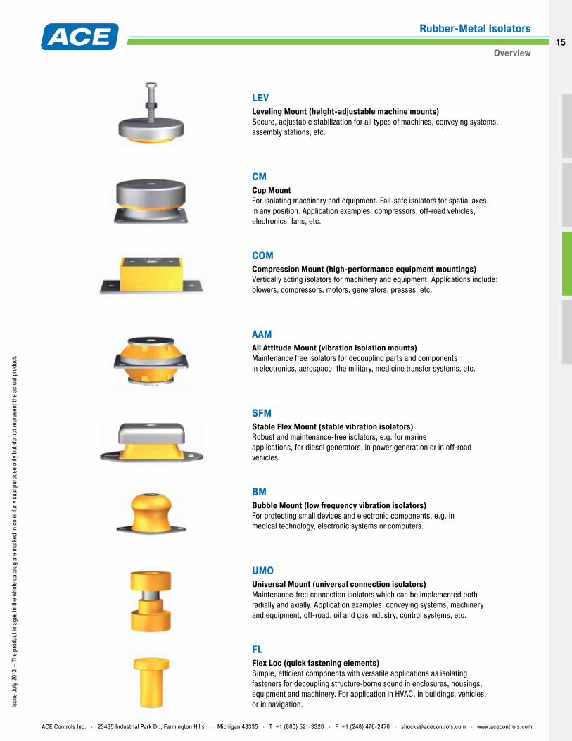
LEV Leveling Mount (height-adjustable machine mounts) Secure, adjustable stabilization for all types of machines, conveying systems, assembly stations, etc.
CM Cup Mount For isolating machinery and equipment. Fail-safe isolators for spatial axes in any position. Application examples: compressors, off-road vehicles, electronics, fans, etc.
COM Compression Mount (high-performance equipment mountings) Vertically acting isolators for machinery and equipment. Applications include: blowers, compressors, motors, generators, presses, etc.
AAM All Attitude Mount (vibration isolation mounts) Maintenance free isolators for decoupling parts and components in electronics, aerospace, the military, medicine transfer systems, etc.
SFM Stable Flex Mount (stable vibration isolators) Robust and maintenance-free isolators, e.g. for marine applications, for diesel generators, in power generation or in off-road vehicles.
BM Bubble Mount (low frequency vibration isolators) For protecting small devices and electronic components, e.g. in medical technology, electronic systems or computers.
UMO Universal Mount (universal connection isolators) Maintenance-free connection isolators which can be implemented both radially and axially. Application examples: conveying systems, machinery and equipment, off-road, oil and gas industry, control systems, etc.
FL Flex Loc (quick fastening elements) Simple, efficient components with versatile applications as isolating fasteners for decoupling structure-borne sound in enclosures, housings, equipment and machinery. For application in HVAC, in buildings, vehicles, or in navigation.
ACE Controls Inc. . 23435 Industrial Park Dr., Farmington Hills . Michigan 48335 . T +1 (800) 521-3320 . F +1 (248) 476-2470 . [email protected] . www.acecontrols.com
Rubber-Metal Isolators
Overview15
Issu
e Ju
ly 2
013
Features and Benefits Easy to level Vibration-reducing Noise-reducing Improved product quality Maintenance-free Compensates for floor unevenness Special models available on request Special vibration-isolating mounts standard and custom-made Neoprene base with a painted steel cover
Areas of Application Injection molding machines Production and processing centers Assembly stations Small presses, etc.
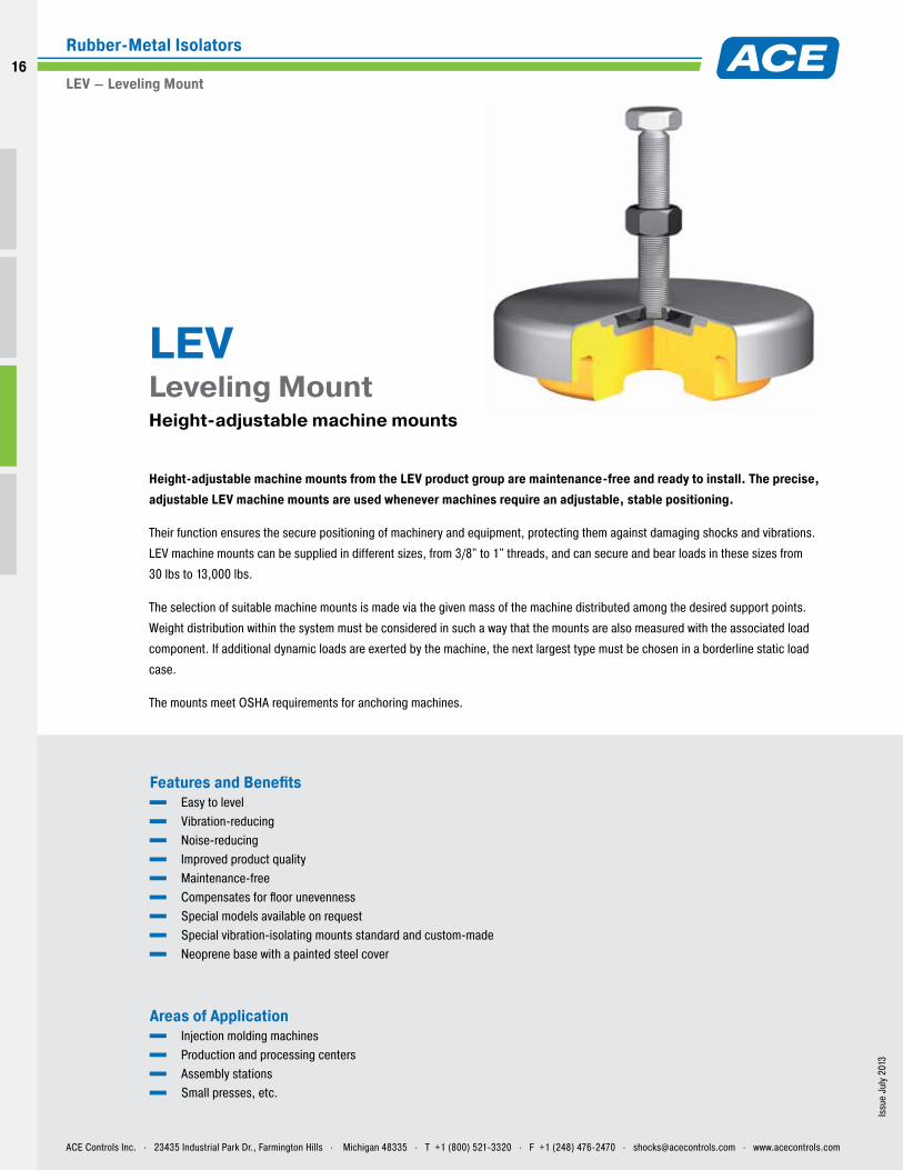
Height-adjustable machine mounts from the LEV product group are maintenance-free and ready to install. The precise, adjustable LEV machine mounts are used whenever machines require an adjustable, stable positioning.
Their function ensures the secure positioning of machinery and equipment, protecting them against damaging shocks and vibrations.
LEV machine mounts can be supplied in different sizes, from 3/8" to 1" threads, and can secure and bear loads in these sizes from
30 lbs to 13,000 lbs.
The selection of suitable machine mounts is made via the given mass of the machine distributed among the desired support points.
Weight distribution within the system must be considered in such a way that the mounts are also measured with the associated load
component. If additional dynamic loads are exerted by the machine, the next largest type must be chosen in a borderline static load
case.
The mounts meet OSHA requirements for anchoring machines.
LEV Leveling Mount Height-adjustable machine mounts
ACE Controls Inc. . 23435 Industrial Park Dr., Farmington Hills . Michigan 48335 . T +1 (800) 521-3320 . F +1 (248) 476-2470 . [email protected] . www.acecontrols.com
Rubber-Metal Isolators
LEV – Leveling Mount
16
16
Issu
e Ju
ly 2
013
– Th
e pr
oduc
t im
ages
in th
e wh
ole
cata
log
are
mar
ked
in c
olor
for v
isua
l pur
pose
onl
y bu
t do
not r
epre
sent
the
actu
al p
rodu
ct.
Type
Min. Load Ibs
Max. LoadIbs
ThreadM
LInch
D Inch
H Inch
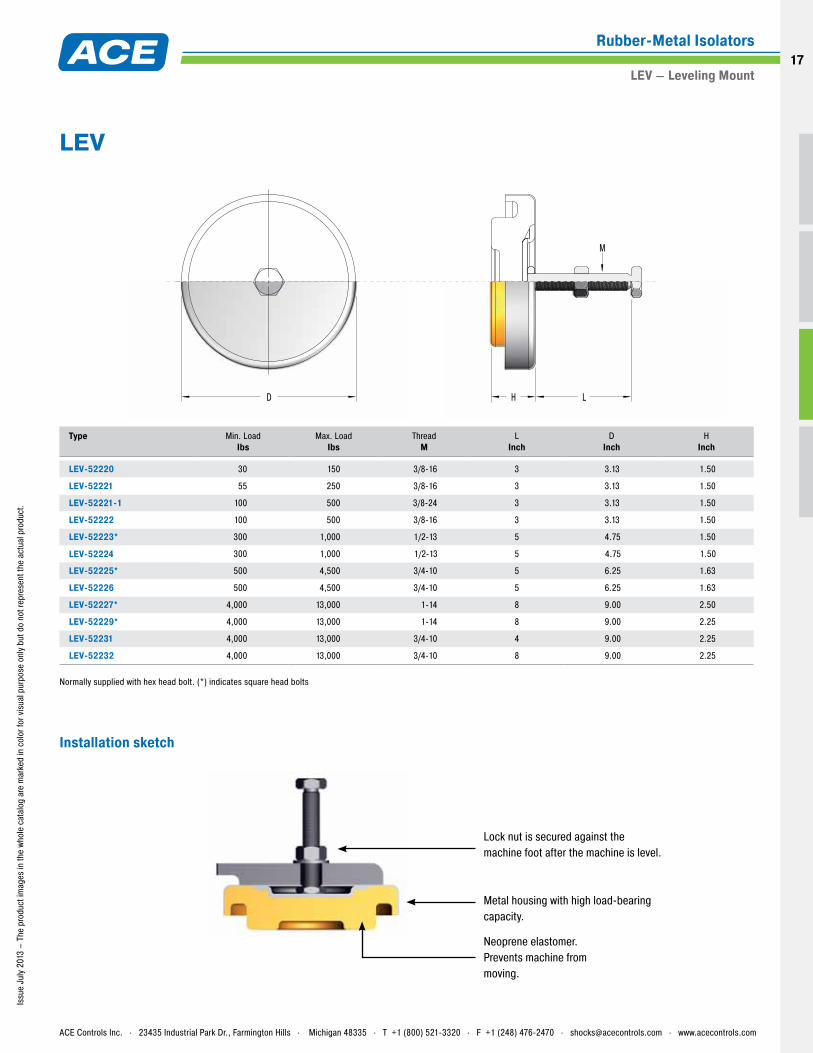
LEV-52220 30 150 3/8-16 3 3.13 1.50
LEV-52221 55 250 3/8-16 3 3.13 1.50
LEV-52221-1 100 500 3/8-24 3 3.13 1.50
LEV-52222 100 500 3/8-16 3 3.13 1.50
LEV-52223* 300 1,000 1/2-13 5 4.75 1.50
LEV-52224 300 1,000 1/2-13 5 4.75 1.50
LEV-52225* 500 4,500 3/4-10 5 6.25 1.63
LEV-52226 500 4,500 3/4-10 5 6.25 1.63
LEV-52227* 4,000 13,000 1-14 8 9.00 2.50
LEV-52229* 4,000 13,000 1-14 8 9.00 2.25
LEV-52231 4,000 13,000 3/4-10 4 9.00 2.25
LEV-52232 4,000 13,000 3/4-10 8 9.00 2.25
Normally supplied with hex head bolt. (*) indicates square head bolts
D H L
M
LEV
Metal housing with high load-bearing capacity.
Neoprene elastomer. Prevents machine from moving.
Lock nut is secured against the machine foot after the machine is level.
Installation sketch
ACE Controls Inc. . 23435 Industrial Park Dr., Farmington Hills . Michigan 48335 . T +1 (800) 521-3320 . F +1 (248) 476-2470 . [email protected] . www.acecontrols.com
Rubber-Metal Isolators
LEV – Leveling Mount17
Issu
e Ju
ly 2
013
Features and Benefits Fail-safe Can be installed in all axes Can be used for shear, compressive and tensile loads Available with standard threads or through-hole core All metal parts galvanized, aluminum or optionally stainless steel available Temperature range -20 °F to +180 °F for neoprene Temperature range -80 °F to +300 °F for high-damping Silicone
Areas of Application Compressors and other vibrating machines Electronic control units and systems Crusher plants Fans and blowers in construction machinery and in buildings Off-road vehicles Shipbuilding Aircraft construction
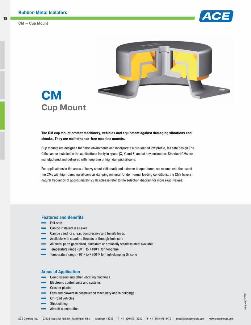
The CM cup mount protect machinery, vehicles and equipment against damaging vibrations and shocks. They are maintenance-free machine mounts.
Cup mounts are designed for harsh enviroments and incorporate a pre-loaded low profile, fail safe design.The
CMs can be installed in the applications freely in space (X, Y and Z) and at any inclination. Standard CMs are
manufactured and delivered with neoprene or high damped silicone.
For applications in the areas of heavy shock (off-road) and extreme temperatures, we recommend the use of
the CMs with high-damping silicone as damping material. Under normal loading conditions, the CMs have a
natural frequency of approximately 25 Hz (please refer to the selection diagram for more exact values).
CM Cup Mount
ACE Controls Inc. . 23435 Industrial Park Dr., Farmington Hills . Michigan 48335 . T +1 (800) 521-3320 . F +1 (248) 476-2470 . [email protected] . www.acecontrols.com
Rubber-Metal Isolators
CM – Cup Mount
18
18
Issu
e Ju
ly 2
013
– Th
e pr
oduc
t im
ages
in th
e wh
ole
cata
log
are
mar
ked
in c
olor
for v
isua
l pur
pose
onl
y bu
t do
not r
epre
sent
the
actu
al p
rodu
ct.
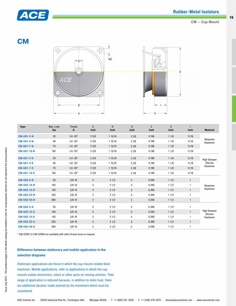
Type
Max. LoadIbs
Thread G
A Inch
B Inch
D Inch
C Inch
H Inch
l Inch
Material
CM-US1-2-N 20 1/4 -20* 2 3/8 1 15/16 2.28 0.196 1 1/8 11/16Neoprene ElastomerCM-US1-4-N 40 1/4 -20* 2 3/8 1 15/16 2.28 0.196 1 1/8 11/16
CM-US1-7-N 70 1/4 -20* 2 3/8 1 15/16 2.28 0.196 1 1/8 11/16
CM-US1-10-N 100 1/4 -20* 2 3/8 1 15/16 2.28 0.196 1 1/8 11/16
CM-US1-2-S 20 1/4 -20* 2 3/8 1 15/16 2.28 0.196 1 1/8 11/16 High Damped Silicone
ElastomerCM-US1-4-S 40 1/4 -20* 2 3/8 1 15/16 2.28 0.196 1 1/8 11/16
CM-US1-7-S 70 1/4 -20* 2 3/8 1 15/16 2.28 0.196 1 1/8 11/16
CM-US1-10-S 100 1/4 -20* 2 3/8 1 15/16 2.28 0.196 1 1/8 11/16
CM-US2-5-N 50 3/8-16 3 2 1/2 3 0.266 1 1/2 1
Neoprene Elastomer
CM-US2-10-N 100 3/8-16 3 2 1/2 3 0.266 1 1/2 1
CM-US2-15-N 150 3/8-16 3 2 1/2 3 0.266 1 1/2 1
CM-US2-25-N 250 3/8-16 3 2 1/2 3 0.266 1 1/2 1
CM-US2-40-N 400 3/8-16 3 2 1/2 3 0.266 1 1/2 1
CM-US2-5-S 50 3/8-16 3 2 1/2 3 0.266 1 1/2 1High Damped
Silicone Elastomer
CM-US2-10-S 100 3/8-16 3 2 1/2 3 0.266 1 1/2 1
CM-US2-15-S 150 3/8-16 3 2 1/2 3 0.266 1 1/2 1
CM-US2-25-S 250 3/8-16 3 2 1/2 3 0.266 1 1/2 1
CM-US2-40-S 400 3/8-16 3 2 1/2 3 0.266 1 1/2 1
* CM-52061 to CM-52069 are available with other thread sizes on request.
B
G 4xC
A
D
H
I
CM
Difference between stationary and mobile application in the selection diagrams
Stationary applications are those in which the cup mounts isolate fixed
machines. Mobile applications, refer to applications in which the cup
mounts isolate electronics, rotors or other parts on moving vehicles. Their
range of application is reduced because, in addition to static load, there
are additional dynamic loads exerted by the movement which must be
considered.
ACE Controls Inc. . 23435 Industrial Park Dr., Farmington Hills . Michigan 48335 . T +1 (800) 521-3320 . F +1 (248) 476-2470 . [email protected] . www.acecontrols.com
Rubber-Metal Isolators
CM – Cup Mount19

2
150140130120110100
9080
70
60
50
40
35
30
25
201816
14
12
10
4
7
9
1012.5
1517.5
2022.5
253035
45
55658090
100110120130150180200220270310350
440
550
10 12 14 16 18 20 25 30 35 4011
US1-2
US1-4
US1-7
US1-10
50%60%70%80%
90% isolation
Mobile application
Natural frequency (Hz)
Load
per
isol
ator
(lbs
)Ex
cita
tion
frequ
ency
(Hz)
2 4 6 8 101214160.4
Static deflection (inch)x0.01
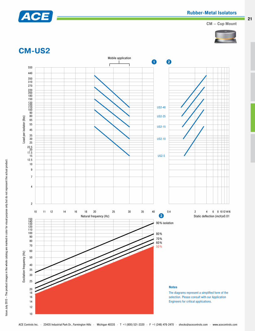
NotesThe diagrams represent a simplified form of the selection. Please consult with our Application Engineers for critical applications.
1 2
3
Issu
e Ju
ly 2
013
– Th
e pr
oduc
t im
ages
in th
e wh
ole
cata
log
are
mar
ked
in c
olor
for v
isua
l pur
pose
onl
y bu
t do
not r
epre
sent
the
actu
al p
rodu
ct.
CM-US1
ACE Controls Inc. . 23435 Industrial Park Dr., Farmington Hills . Michigan 48335 . T +1 (800) 521-3320 . F +1 (248) 476-2470 . [email protected] . www.acecontrols.com
Rubber-Metal Isolators
CM – Cup Mount
20
20
2
150140130120110100
9080
70
60
50
40
35
30
25
201816
14
12
10
4
7
9
1012.5
1517.5
2022.5
253035
45
55658090
100110120130150180200220270310350
440
550
10 12 14 16 18 20 25 30 35 4011
US2-5
US2-10
US2-15
US2-40
US2-25
50%60%70%80%
90% isolation
Natural frequency (Hz)
Load
per
isol
ator
(lbs
)Ex
cita
tion
frequ
ency
(Hz)
Static deflection (inch)x0.01
Mobile application
2 4 6 8 101214160.4
NotesThe diagrams represent a simplified form of the selection. Please consult with our Application Engineers for critical applications.
1 2
3
Issu
e Ju
ly 2
013
– Th
e pr
oduc
t im
ages
in th
e wh
ole
cata
log
are
mar
ked
in c
olor
for v
isua
l pur
pose
onl
y bu
t do
not r
epre
sent
the
actu
al p
rodu
ct.
CM-US2
ACE Controls Inc. . 23435 Industrial Park Dr., Farmington Hills . Michigan 48335 . T +1 (800) 521-3320 . F +1 (248) 476-2470 . [email protected] . www.acecontrols.com
Rubber-Metal Isolators
CM – Cup Mount21
Issu
e Ju
ly 2
013
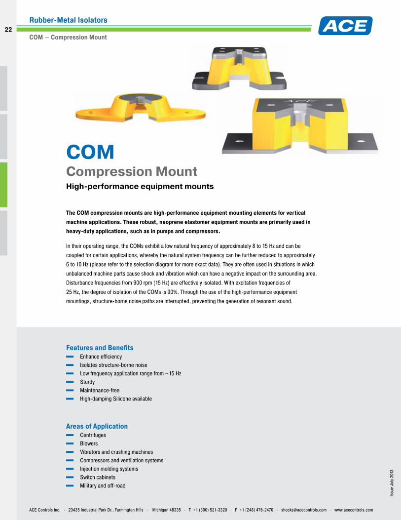
Features and Benefits Enhance efficiency Isolates structure-borne noise Low frequency application range from ~15 Hz Sturdy Maintenance-free High-damping Silicone available
Areas of Application Centrifuges Blowers Vibrators and crushing machines Compressors and ventilation systems Injection molding systems Switch cabinets Military and off-road
The COM compression mounts are high-performance equipment mounting elements for vertical machine applications. These robust, neoprene elastomer equipment mounts are primarily used in heavy-duty applications, such as in pumps and compressors.
In their operating range, the COMs exhibit a low natural frequency of approximately 8 to 15 Hz and can be
coupled for certain applications, whereby the natural system frequency can be further reduced to approximately
6 to 10 Hz (please refer to the selection diagram for more exact data). They are often used in situations in which
unbalanced machine parts cause shock and vibration which can have a negative impact on the surrounding area.
Disturbance frequencies from 900 rpm (15 Hz) are effectively isolated. With excitation frequencies of
25 Hz, the degree of isolation of the COMs is 90%. Through the use of the high-performance equipment
mountings, structure-borne noise paths are interrupted, preventing the generation of resonant sound.
COM Compression Mount High-performance equipment mounts
ACE Controls Inc. . 23435 Industrial Park Dr., Farmington Hills . Michigan 48335 . T +1 (800) 521-3320 . F +1 (248) 476-2470 . [email protected] . www.acecontrols.com
Rubber-Metal Isolators
COM – Compression Mount
22
22
Issu
e Ju
ly 2
013
– Th
e pr
oduc
t im
ages
in th
e wh
ole
cata
log
are
mar
ked
in c
olor
for v
isua
l pur
pose
onl
y bu
t do
not r
epre
sent
the
actu
al p
rodu
ct.
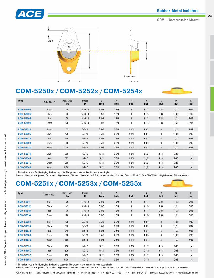
Type Color Code* Max. Load
lbsThread
ML
InchW
InchH
InchA
InchC
InchD
InchE
Inch
COM-52501 Blue 35 5/16-18 3 1/8 1 3/4 1 1 1/4 2 3/8 11/32 3/16
COM-52502 Black 45 5/16-18 3 1/8 1 3/4 1 1 1/4 2 3/8 11/32 3/16
COM-52503 Red 70 5/16-18 3 1/8 1 3/4 1 1 1/4 2 3/8 11/32 3/16
COM-52504 Green 120 5/16-18 3 1/8 1 3/4 1 1 1/4 2 3/8 11/32 3/16
COM-52521 Blue 135 3/8-16 3 7/8 2 3/8 1 1/4 1 3/4 3 11/32 7/32
COM-52522 Black 170 3/8-16 3 7/8 2 3/8 1 1/4 1 3/4 3 11/32 7/32
COM-52523 Red 240 3/8-16 3 7/8 2 3/8 1 1/4 1 3/4 3 11/32 7/32
COM-52524 Green 380 3/8-16 3 7/8 2 3/8 1 1/4 1 3/4 3 11/32 7/32
COM-52525 Gray 550 3/8-16 3 7/8 2 3/8 1 1/4 1 3/4 3 11/32 7/32
COM-52541 Black 250 1/2-13 51/2 3 3/8 1 3/4 21/2 4 1/8 9/16 1/4
COM-52542 Red 525 1/2-13 51/2 3 3/8 1 3/4 21/2 4 1/8 9/16 1/4
COM-52543 Green 750 1/2-13 51/2 3 3/8 1 3/4 21/2 4 1/8 9/16 1/4
COM-52544 Gray 1100 1/2-13 51/2 3 3/8 1 3/4 21/2 4 1/8 9/16 1/4
* The color code is for identifying the load capacity. The products are marked in color accordingly. Standard Material: Neoprene. On request: High Damped Silicone, please add -HDS to the part number. Example: COM-52501-HDS for COM-52501 as High Damped Silicone version.
Type Color Code* Max. Load
lbsThread
ML
InchW
InchH
InchA
InchC
InchD
InchE
Inch
COM-52511 Blue 35 5/16-18 3 1/8 1 3/4 1 1 1/4 2 3/8 11/32 3/16
COM-52512 Black 45 5/16-18 3 1/8 1 3/4 1 1 1/4 2 3/8 11/32 3/16
COM-52513 Red 70 5/16-18 3 1/8 1 3/4 1 1 1/4 2 3/8 11/32 3/16
COM-52514 Green 120 5/16-18 3 1/8 1 3/4 1 1 1/4 2 3/8 11/32 3/16
COM-52531 Blue 135 3/8-16 3 7/8 2 3/8 1 1/4 1 3/4 3 11/32 7/32
COM-52532 Black 170 3/8-16 3 7/8 2 3/8 1 1/4 1 3/4 3 11/32 7/32
COM-52533 Red 240 3/8-16 3 7/8 2 3/8 1 1/4 1 3/4 3 11/32 7/32
COM-52534 Green 380 3/8-16 3 7/8 2 3/8 1 1/4 1 3/4 3 11/32 7/32
COM-52535 Gray 550 3/8-16 3 7/8 2 3/8 1 1/4 1 3/4 3 11/32 7/32
COM-52551 Black 250 1/2-13 51/2 3 3/8 1 3/4 2 1/2 4 1/8 9/16 1/4
COM-52552 Red 525 1/2-13 51/2 3 3/8 1 3/4 2 1/2 4 1/8 9/16 1/4
COM-52553 Green 750 1/2-13 51/2 3 3/8 1 3/4 2 1/2 4 1/8 9/16 1/4
COM-52554 Gray 1100 1/2-13 51/2 3 3/8 1 3/4 2 1/2 4 1/8 9/16 1/4
* The color code is for identifying the loading capacity. The products are marked in color accordingly. Standard Material: Neoprene. On request: High Damped Silicone, please add -HDS to the part number. Example: COM-52511-HDS for COM-52511 as High Damped Silicone version.
M
2xØD
W
LC A
H
E
COM-5251x / COM-5253x / COM-5255x
COM-5250x / COM-5252x / COM-5254x
ACE Controls Inc. . 23435 Industrial Park Dr., Farmington Hills . Michigan 48335 . T +1 (800) 521-3320 . F +1 (248) 476-2470 . [email protected] . www.acecontrols.com
Rubber-Metal Isolators
COM – Compression Mount23
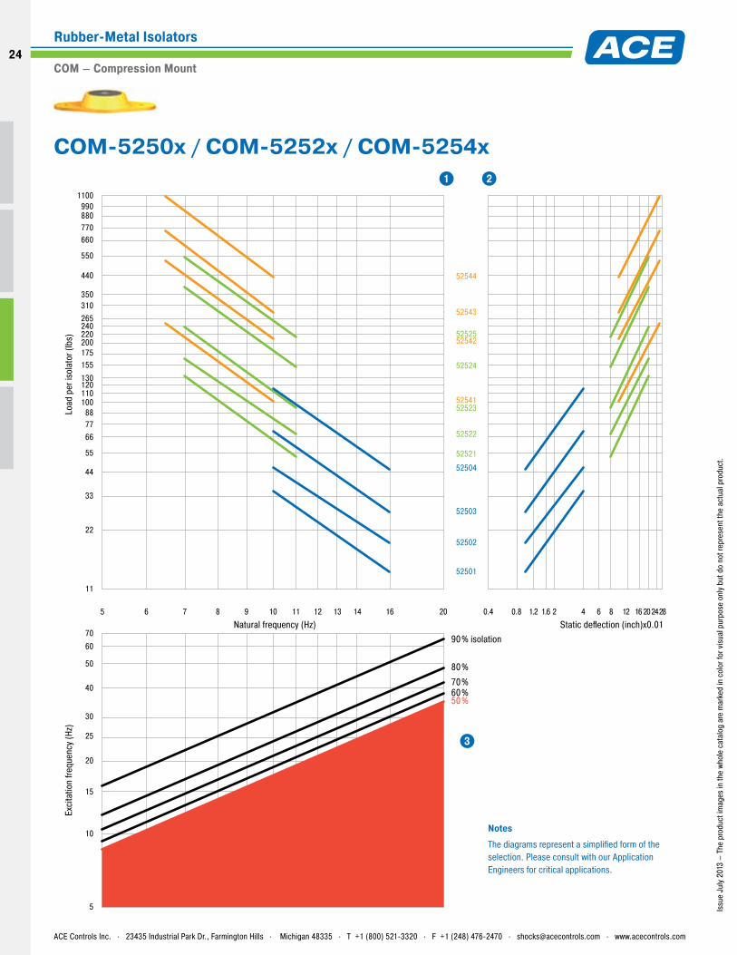
11
22
33
44
55
667788
100110
130
155
120
175200220240265310350
440
770660
550
880990
1100
1.20.8 1.6 2 4 6 8 16 28242012
0.4
52501
52502
52503
52504
52521
52522
52523
52524
52541
52542
52543
52544
52525
70
50
60
40
30
25
20
15
10
5
5 7 8 9 10 11 12 13 14 16 206
Natural frequency (Hz)
Load
per
isol
ator
(lbs
)
Static deflection (inch)x0.01
Exci
tatio
n fre
quen
cy (H
z)
50%60%70%
80%
90% isolation
NotesThe diagrams represent a simplified form of the selection. Please consult with our Application Engineers for critical applications.
1 2
3
Issu
e Ju
ly 2
013
– Th
e pr
oduc
t im
ages
in th
e wh
ole
cata
log
are
mar
ked
in c
olor
for v
isua
l pur
pose
onl
y bu
t do
not r
epre
sent
the
actu
al p
rodu
ct.
COM-5250x / COM-5252x / COM-5254x
ACE Controls Inc. . 23435 Industrial Park Dr., Farmington Hills . Michigan 48335 . T +1 (800) 521-3320 . F +1 (248) 476-2470 . [email protected] . www.acecontrols.com
Rubber-Metal Isolators
COM – Compression Mount
24
24
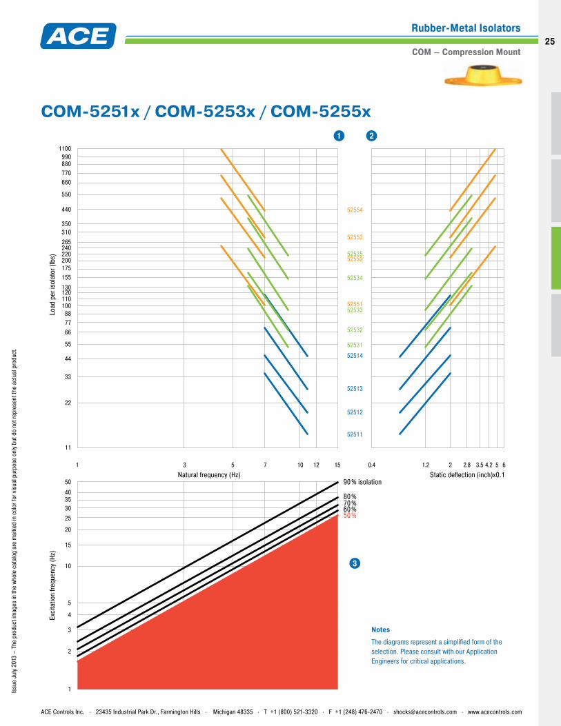
1 3 5 7 10 12 15 1.2 2 2.8 3.5 4.2 5 6
0.4
50%60%70%80%
90% isolation
52512
52513
52514
52511
52531
52532
52533
52534
52551
52552
52553
52554
52535
Natural frequency (Hz)
Load
per
isol
ator
(lbs
)
40
50
353025
20
15
10
5
4
3
2
1
Static deflection (inch)x0.1
Exci
tatio
n fre
quen
cy (H
z)
11
22
33
44
55
667788
100110
130
155
120
175200220240265310350
440
770660
550
880990
1100
NotesThe diagrams represent a simplified form of the selection. Please consult with our Application Engineers for critical applications.
1 2
3
Issu
e Ju
ly 2
013
– Th
e pr
oduc
t im
ages
in th
e wh
ole
cata
log
are
mar
ked
in c
olor
for v
isua
l pur
pose
onl
y bu
t do
not r
epre
sent
the
actu
al p
rodu
ct.
COM-5251x / COM-5253x / COM-5255x
ACE Controls Inc. . 23435 Industrial Park Dr., Farmington Hills . Michigan 48335 . T +1 (800) 521-3320 . F +1 (248) 476-2470 . [email protected] . www.acecontrols.com
Rubber-Metal Isolators
COM – Compression Mount25
Standard Material: NeopreneOn request: High Damped Silicone, please add -HDS to the part number. Example: COM-52561-HDS for COM-52561 as High Damped Silicone version.
Standard Material: Neoprene
Standard Material: Neoprene
Issu
e Ju
ly 2
013
– Th
e pr
oduc
t im
ages
in th
e wh
ole
cata
log
are
mar
ked
in c
olor
for v
isua
l pur
pose
onl
y bu
t do
not r
epre
sent
the
actu
al p
rodu
ct.
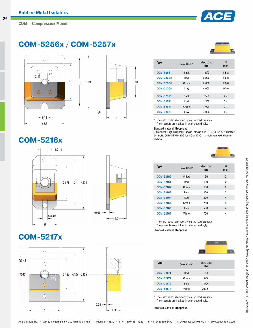
Type Color Code* Max. Load
IbsW
Inch
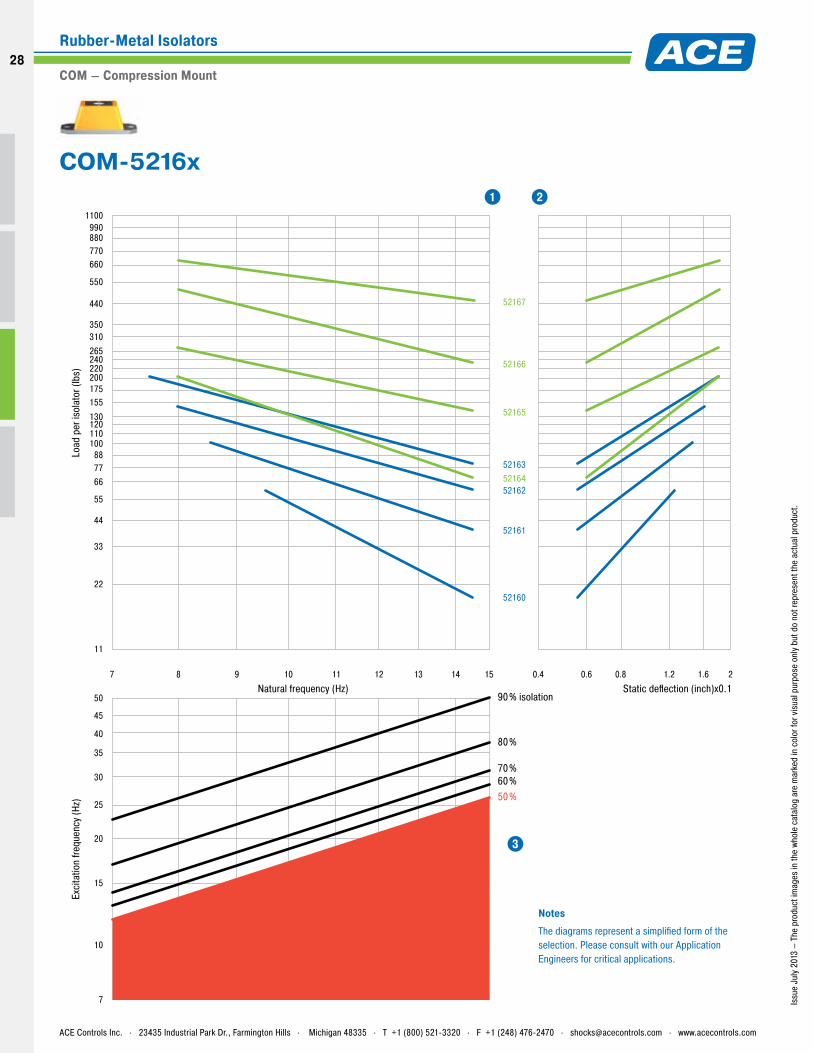
COM-52160 Yellow 60 2
COM-52161 Red 100 2
COM-52162 Green 150 2
COM-52163 Blue 200 2
COM-52164 Red 200 4
COM-52165 Green 280 4
COM-52166 Blue 500 4
COM-52167 White 700 4
* The color code is for identifying the load capacity. The products are marked in color accordingly.
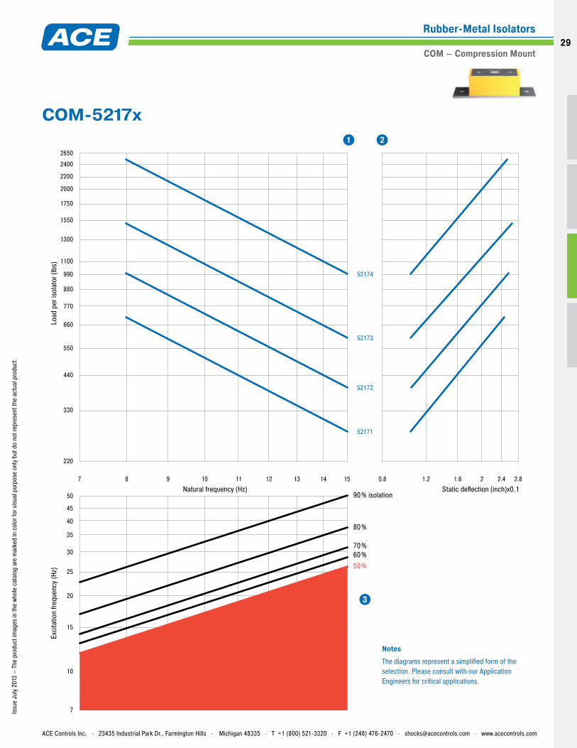
Type Color Code* Max. Load
Ibs
COM-52171 Red 700
COM-52172 Green 1,000
COM-52173 Blue 1,500
COM-52174 White 2,500
* The color code is for identifying the load capacity. The products are marked in color accordingly.
Type Color Code* Max. Load
IbsH
Inch
COM-52561 Black 1,500 1-5/8
COM-52562 Red 2,250 1-5/8
COM-52563 Green 3,000 1-5/8
COM-52564 Gray 4,000 1-5/8
COM-52571 Black 1,500 2¾
COM-52572 Red 2,250 2¾
COM-52573 Green 3,000 2¾
COM-52574 Gray 4,000 2¾
* The color code is for identifying the load capacity. The products are marked in color accordingly.
3
5.1254.1253.125
1.61
0.25
2x0.44
1/2-13
1/2-13
W
4.3753 3/42.875
2x0.4061.5
0.095
9/16
4 5/8
53.7 6 1/4
1/2-13
3 3/4
H
3/8
COM-5256x / COM-5257x
COM-5217x
COM-5216x
ACE Controls Inc. . 23435 Industrial Park Dr., Farmington Hills . Michigan 48335 . T +1 (800) 521-3320 . F +1 (248) 476-2470 . [email protected] . www.acecontrols.com
Rubber-Metal Isolators
COM – Compression Mount
26
26
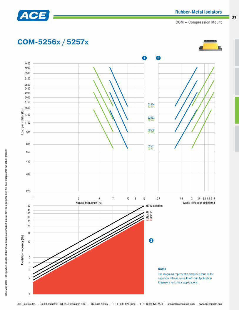
220
330
440
550
660
900
1100
1300
1550
1750
2000
2200
2400
3100
2650
3500
4000
4400
52561
52562
52563
52564
52571
52572
52573
52574
1 3 5 7 10 12 15
40
50
353025
20
15
10
5
4
3
2
1
Static deflection (inch)x0.1Natural frequency (Hz)
Load
per
isol
ator
(lbs
)
50%60%70%80%
90% isolation
Exci
tatio
n fre
quen
cy (H
z)
1.2 2 2.8 3.5 4.2 5 60.4
NotesThe diagrams represent a simplified form of the selection. Please consult with our Application Engineers for critical applications.
1 2
3
Issu
e Ju
ly 2
013
– Th
e pr
oduc
t im
ages
in th
e wh
ole
cata
log
are
mar
ked
in c
olor
for v
isua
l pur
pose
onl
y bu
t do
not r
epre
sent
the
actu
al p
rodu
ct.
COM-5256x / 5257x
ACE Controls Inc. . 23435 Industrial Park Dr., Farmington Hills . Michigan 48335 . T +1 (800) 521-3320 . F +1 (248) 476-2470 . [email protected] . www.acecontrols.com
Rubber-Metal Isolators
COM – Compression Mount27
0.6 0.8 1.2 1.6 20.47 9 108 11 12 13 14 15
Natural frequency (Hz)
Load
per
isol
ator
(lbs
)
50
45
40
35
30
20
25
10
15
7
Static deflection (inch)x0.1
Exci
tatio
n fre
quen
cy (H
z)
11
22
33
44
55
667788
100110
130
155
120
175200220240265310350
440
770660
550
880990
1100
52160
52161
52165
52166
52167
52162
5216352164
50%60%70%
80%
90% isolation
NotesThe diagrams represent a simplified form of the selection. Please consult with our Application Engineers for critical applications.
1 2
3
Issu
e Ju
ly 2
013
– Th
e pr
oduc
t im
ages
in th
e wh
ole
cata
log
are
mar
ked
in c
olor
for v
isua
l pur
pose
onl
y bu
t do
not r
epre
sent
the
actu
al p
rodu
ct.
COM-5216x
ACE Controls Inc. . 23435 Industrial Park Dr., Farmington Hills . Michigan 48335 . T +1 (800) 521-3320 . F +1 (248) 476-2470 . [email protected] . www.acecontrols.com
Rubber-Metal Isolators
COM – Compression Mount
28
28
220
330
440
550
660
770
880
990
1100
1300
1550
2000
1750
2200
2400
2650
52171
1.2 1.6 2 2.4 2.80.8
50
45
40
35
30
20
25
10
15
7
Natural frequency (Hz)
Load
per
isol
ator
(lbs
)
7 9 108 11 12 13 14 15
52172
50%60%70%
80%
90% isolationStatic deflection (inch)x0.1
Exci
tatio
n fre
quen
cy (H
z)
52173
52174
NotesThe diagrams represent a simplified form of the selection. Please consult with our Application Engineers for critical applications.
1 2
3
Issu
e Ju
ly 2
013
– Th
e pr
oduc
t im
ages
in th
e wh
ole
cata
log
are
mar
ked
in c
olor
for v
isua
l pur
pose
onl
y bu
t do
not r
epre
sent
the
actu
al p
rodu
ct.
COM-5217x
ACE Controls Inc. . 23435 Industrial Park Dr., Farmington Hills . Michigan 48335 . T +1 (800) 521-3320 . F +1 (248) 476-2470 . [email protected] . www.acecontrols.com
Rubber-Metal Isolators
COM – Compression Mount29
Issu
e Ju
ly 2
013
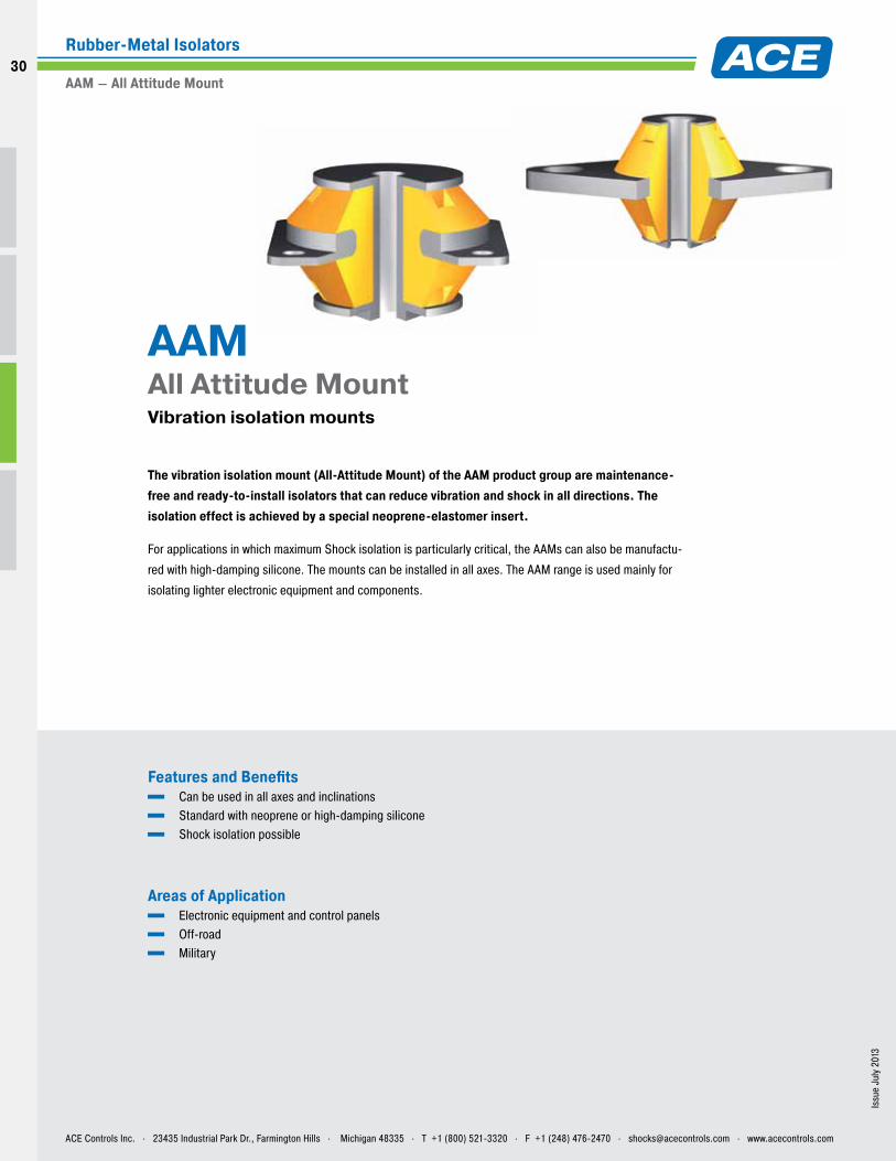
Features and Benefits Can be used in all axes and inclinations Standard with neoprene or high-damping silicone Shock isolation possible
Areas of Application Electronic equipment and control panels Off-road Military
The vibration isolation mount (All-Attitude Mount) of the AAM product group are maintenance-free and ready-to-install isolators that can reduce vibration and shock in all directions. The isolation effect is achieved by a special neoprene-elastomer insert.
For applications in which maximum Shock isolation is particularly critical, the AAMs can also be manufactu-
red with high-damping silicone. The mounts can be installed in all axes. The AAM range is used mainly for
isolating lighter electronic equipment and components.
AAM All Attitude Mount Vibration isolation mounts
ACE Controls Inc. . 23435 Industrial Park Dr., Farmington Hills . Michigan 48335 . T +1 (800) 521-3320 . F +1 (248) 476-2470 . [email protected] . www.acecontrols.com
Rubber-Metal Isolators
AAM – All Attitude Mount
30
30
Issu
e Ju
ly 2
013
– Th
e pr
oduc
t im
ages
in th
e wh
ole
cata
log
are
mar
ked
in c
olor
for v
isua
l pur
pose
onl
y bu
t do
not r
epre
sent
the
actu
al p
rodu
ct.
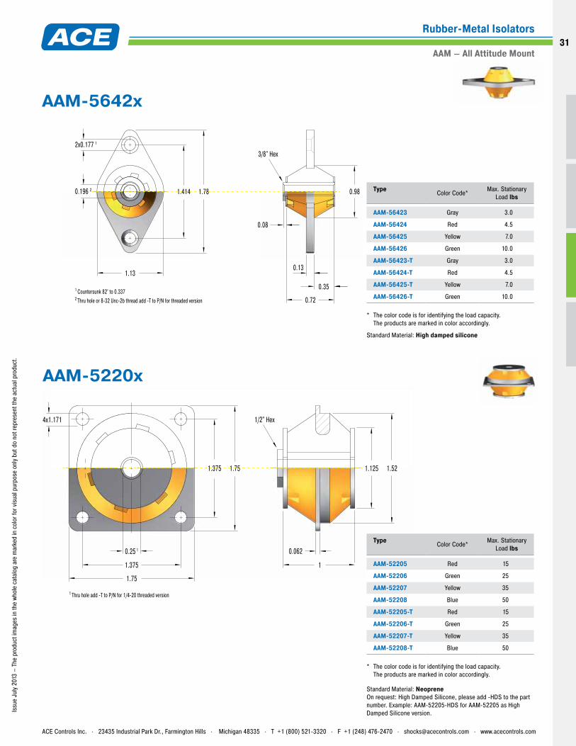
4x1.171 1/2" Hex
1.75
0.25 1
1 Thru hole add -T to P/N for 1/4-20 threaded version
1.375
1.751.375 1.125 1.52
1
0.062
Type Color Code* Max. Stationary
Load lbs
AAM-56423 Gray 3.0
AAM-56424 Red 4.5
AAM-56425 Yellow 7.0
AAM-56426 Green 10.0
AAM-56423-T Gray 3.0
AAM-56424-T Red 4.5
AAM-56425-T Yellow 7.0
AAM-56426-T Green 10.0
* The color code is for identifying the load capacity. The products are marked in color accordingly.
Standard Material: High damped silicone
Type Color Code* Max. Stationary
Load lbs
AAM-52205 Red 15
AAM-52206 Green 25
AAM-52207 Yellow 35
AAM-52208 Blue 50
AAM-52205-T Red 15
AAM-52206-T Green 25
AAM-52207-T Yellow 35
AAM-52208-T Blue 50
* The color code is for identifying the load capacity. The products are marked in color accordingly.
1.13
1.781.414 0.98
0.72
0.35
0.13
0.08
2x0.177 1
0.196 2
1 Countersunk 82° to 0.3372 Thru hole or 8-32 Unc-2b thread add -T to P/N for threaded version
3/8" Hex
AAM-5642x
AAM-5220x
Standard Material: NeopreneOn request: High Damped Silicone, please add -HDS to the part number. Example: AAM-52205-HDS for AAM-52205 as High Damped Silicone version.
ACE Controls Inc. . 23435 Industrial Park Dr., Farmington Hills . Michigan 48335 . T +1 (800) 521-3320 . F +1 (248) 476-2470 . [email protected] . www.acecontrols.com
Rubber-Metal Isolators
AAM – All Attitude Mount31
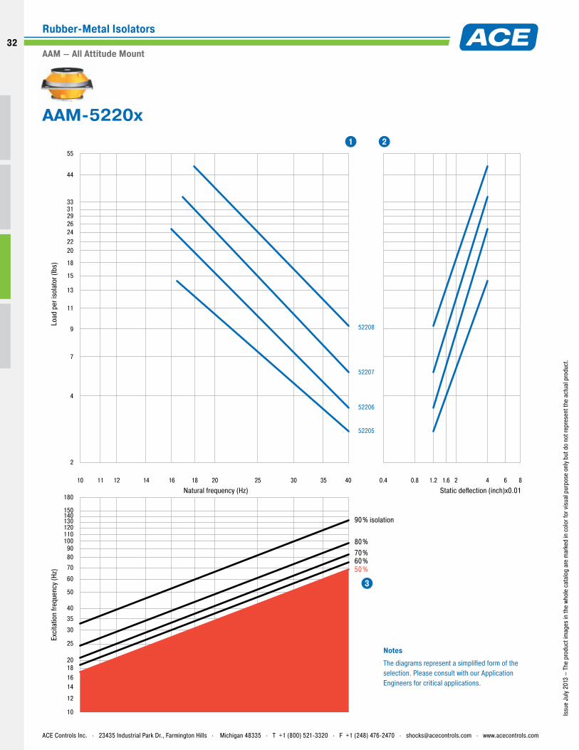
2
150
180
140130120110100
9080
70
60
50
40
35
30
25
20181614
12
10
4
7
9
11
13
15
18
20222426293133
44
55
10 12 14 16 18 20 25 30 35 4011
52205
52206
52207
52208
50%60%70%80%
90% isolation
0.8 1.2 1.6 2 4 6 80.4
Natural frequency (Hz)
Load
per
isol
ator
(lbs
)
Static deflection (inch)x0.01
Exci
tatio
n fre
quen
cy (H
z)
NotesThe diagrams represent a simplified form of the selection. Please consult with our Application Engineers for critical applications.
1 2
3
Issu
e Ju
ly 2
013
– Th
e pr
oduc
t im
ages
in th
e wh
ole
cata
log
are
mar
ked
in c
olor
for v
isua
l pur
pose
onl
y bu
t do
not r
epre
sent
the
actu
al p
rodu
ct.
AAM-5220x
ACE Controls Inc. . 23435 Industrial Park Dr., Farmington Hills . Michigan 48335 . T +1 (800) 521-3320 . F +1 (248) 476-2470 . [email protected] . www.acecontrols.com
Rubber-Metal Isolators
AAM – All Attitude Mount
32
32
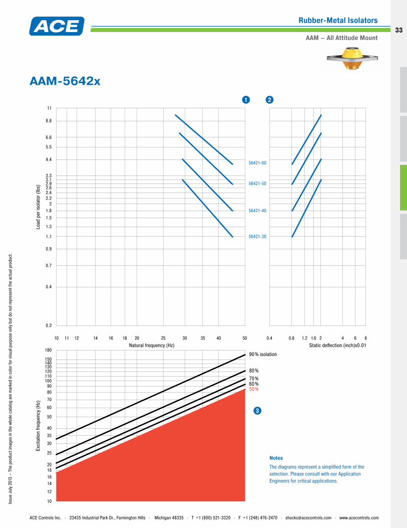
0.2
0.4
0.7
0.9
1.1
1.5
1.3
1.82
2.22.42.62.93.13.3
4.4
5.5
6.6
8.8
11
10 12 14 16 18 20 25 30 35 40 5011
56421-30
56421-40
56421-50
56421-60
50%60%70%80%
90% isolation150
180
140130120110100
9080
70
60
50
40
35
30
25
20181614
12
10
0.8 1.2 1.6 2 4 6 80.4
Natural frequency (Hz)
Load
per
isol
ator
(lbs
)Ex
cita
tion
frequ
ency
(Hz)
Static deflection (inch)x0.01
NotesThe diagrams represent a simplified form of the selection. Please consult with our Application Engineers for critical applications.
1 2
3
Issu
e Ju
ly 2
013
– Th
e pr
oduc
t im
ages
in th
e wh
ole
cata
log
are
mar
ked
in c
olor
for v
isua
l pur
pose
onl
y bu
t do
not r
epre
sent
the
actu
al p
rodu
ct.
AAM-5642x
ACE Controls Inc. . 23435 Industrial Park Dr., Farmington Hills . Michigan 48335 . T +1 (800) 521-3320 . F +1 (248) 476-2470 . [email protected] . www.acecontrols.com
Rubber-Metal Isolators
AAM – All Attitude Mount33
Issu
e Ju
ly 2
013
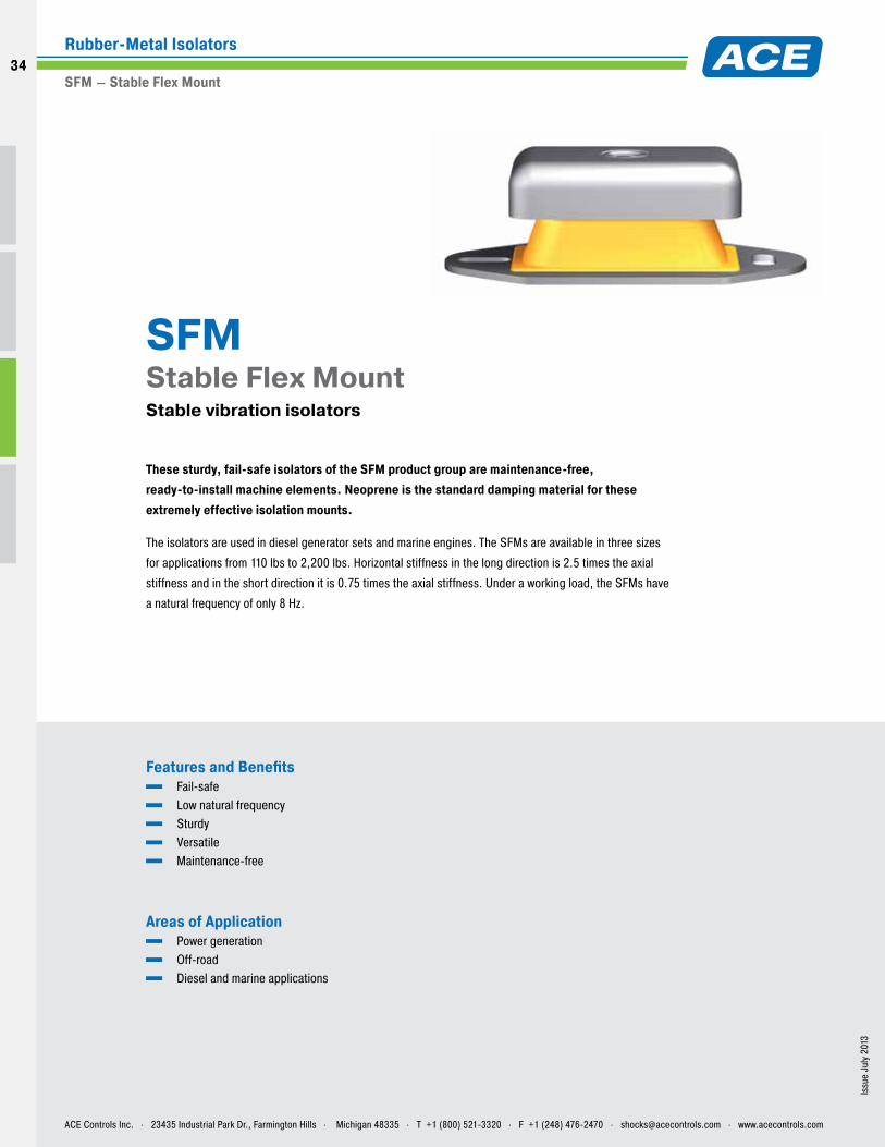
Features and Benefits Fail-safe Low natural frequency Sturdy Versatile Maintenance-free
Areas of Application Power generation Off-road Diesel and marine applications
These sturdy, fail-safe isolators of the SFM product group are maintenance-free, ready-to-install machine elements. Neoprene is the standard damping material for these extremely effective isolation mounts.
The isolators are used in diesel generator sets and marine engines. The SFMs are available in three sizes
for applications from 110 lbs to 2,200 lbs. Horizontal stiffness in the long direction is 2.5 times the axial
stiffness and in the short direction it is 0.75 times the axial stiffness. Under a working load, the SFMs have
a natural frequency of only 8 Hz.
SFM Stable Flex Mount Stable vibration isolators
ACE Controls Inc. . 23435 Industrial Park Dr., Farmington Hills . Michigan 48335 . T +1 (800) 521-3320 . F +1 (248) 476-2470 . [email protected] . www.acecontrols.com
Rubber-Metal Isolators
SFM – Stable Flex Mount
34
34
Issu
e Ju
ly 2
013
– Th
e pr
oduc
t im
ages
in th
e wh
ole
cata
log
are
mar
ked
in c
olor
for v
isua
l pur
pose
onl
y bu
t do
not r
epre
sent
the
actu
al p
rodu
ct.
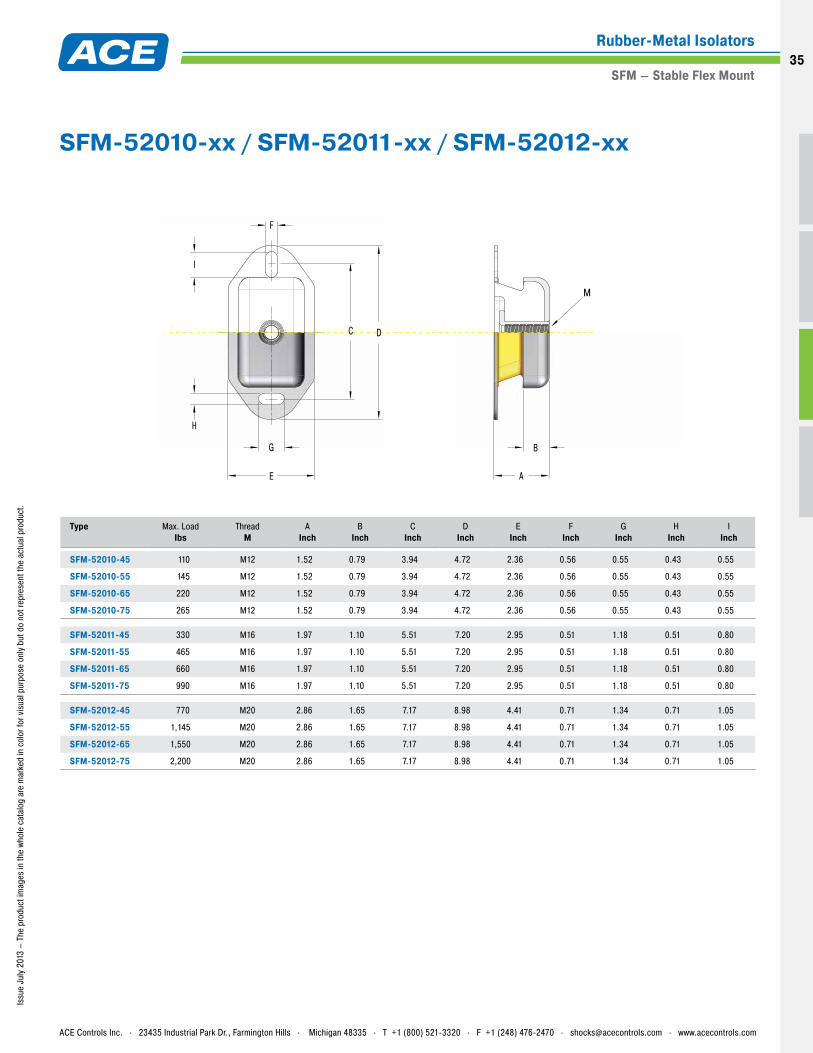
Type
Max. Load Ibs
ThreadM
AInch
BInch
CInch
DInch
EInch
FInch
GInch
HInch
IInch
SFM-52010-45 110 M12 1.52 0.79 3.94 4.72 2.36 0.56 0.55 0.43 0.55
SFM-52010-55 145 M12 1.52 0.79 3.94 4.72 2.36 0.56 0.55 0.43 0.55
SFM-52010-65 220 M12 1.52 0.79 3.94 4.72 2.36 0.56 0.55 0.43 0.55
SFM-52010-75 265 M12 1.52 0.79 3.94 4.72 2.36 0.56 0.55 0.43 0.55
SFM-52011-45 330 M16 1.97 1.10 5.51 7.20 2.95 0.51 1.18 0.51 0.80
SFM-52011-55 465 M16 1.97 1.10 5.51 7.20 2.95 0.51 1.18 0.51 0.80
SFM-52011-65 660 M16 1.97 1.10 5.51 7.20 2.95 0.51 1.18 0.51 0.80
SFM-52011-75 990 M16 1.97 1.10 5.51 7.20 2.95 0.51 1.18 0.51 0.80
SFM-52012-45 770 M20 2.86 1.65 7.17 8.98 4.41 0.71 1.34 0.71 1.05
SFM-52012-55 1,145 M20 2.86 1.65 7.17 8.98 4.41 0.71 1.34 0.71 1.05
SFM-52012-65 1,550 M20 2.86 1.65 7.17 8.98 4.41 0.71 1.34 0.71 1.05
SFM-52012-75 2,200 M20 2.86 1.65 7.17 8.98 4.41 0.71 1.34 0.71 1.05
I
G
F
H
E
DC
A
B
M
SFM-52010-xx / SFM-52011-xx / SFM-52012-xx
ACE Controls Inc. . 23435 Industrial Park Dr., Farmington Hills . Michigan 48335 . T +1 (800) 521-3320 . F +1 (248) 476-2470 . [email protected] . www.acecontrols.com
Rubber-Metal Isolators
SFM – Stable Flex Mount35
22
33
50
40
30
25
20
15
10
5
44
55
66
88
110
130155175200220
330
440
550
660
880
1550
1300
1100
1750
2200
5 6 7 8 9 10 12 1311 14 15 0.6 0.8 1.2 1.6 2 2.4
0.4
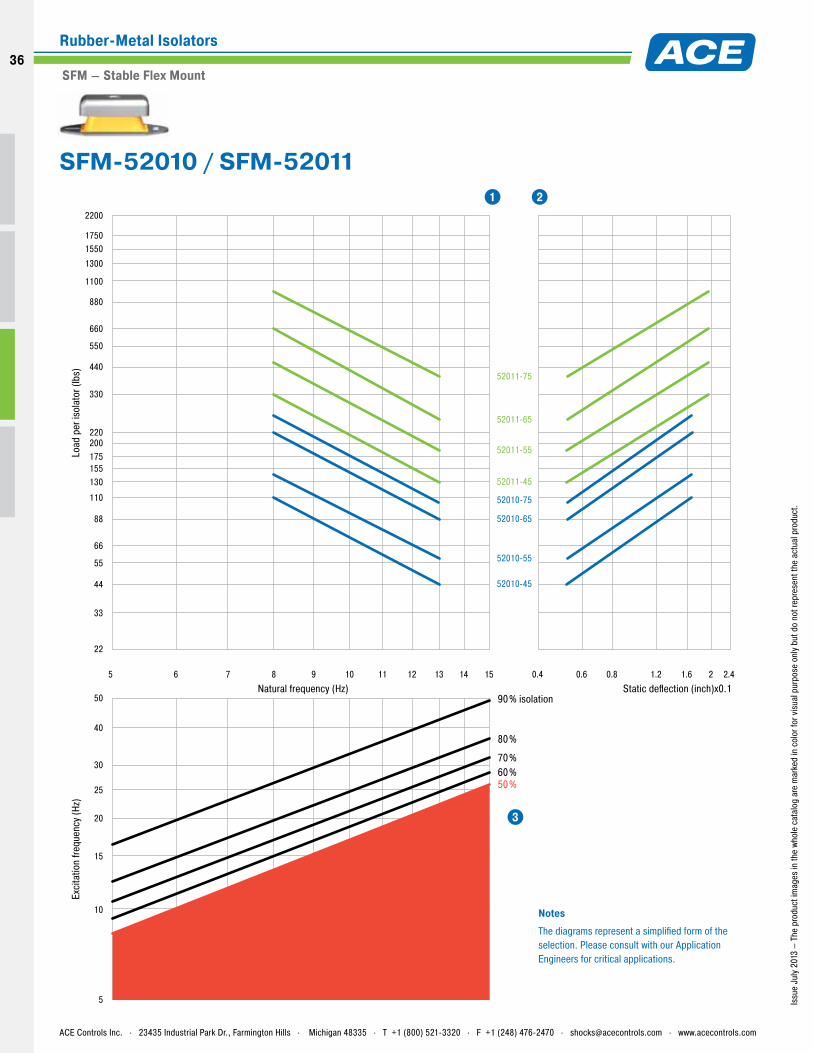
52010-45
52010-55
52010-65
52010-75
52011-45
52011-55
52011-65
52011-75
Natural frequency (Hz)
Load
per
isol
ator
(lbs
)
50%60%70%
80%
90% isolationStatic deflection (inch)x0.1
Exci
tatio
n fre
quen
cy (H
z)
NotesThe diagrams represent a simplified form of the selection. Please consult with our Application Engineers for critical applications.
1 2
3
Issu
e Ju
ly 2
013
– Th
e pr
oduc
t im
ages
in th
e wh
ole
cata
log
are
mar
ked
in c
olor
for v
isua
l pur
pose
onl
y bu
t do
not r
epre
sent
the
actu
al p
rodu
ct.
SFM-52010 / SFM-52011
ACE Controls Inc. . 23435 Industrial Park Dr., Farmington Hills . Michigan 48335 . T +1 (800) 521-3320 . F +1 (248) 476-2470 . [email protected] . www.acecontrols.com
Rubber-Metal Isolators
SFM – Stable Flex Mount
36
36
50
40
30
25
20
15
10
5
5 6 7 8 9 10 12 1311 14 15
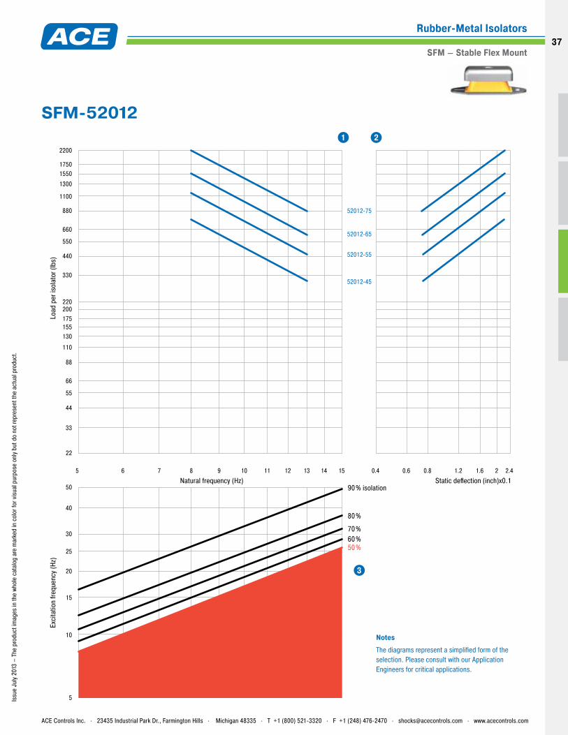
52012-55
52012-65
52012-75
52012-45
50%60%70%
80%
90% isolationNatural frequency (Hz)
Load
per
isol
ator
(lbs
)Ex
cita
tion
frequ
ency
(Hz)
0.6 0.8 1.2 1.6 2 2.40.4
Static deflection (inch)x0.1
22
33
44
55
66
88
110
130155175200220
330
440
550
660
880
1550
1300
1100
1750
2200
NotesThe diagrams represent a simplified form of the selection. Please consult with our Application Engineers for critical applications.
1 2
3
Issu
e Ju
ly 2
013
– Th
e pr
oduc
t im
ages
in th
e wh
ole
cata
log
are
mar
ked
in c
olor
for v
isua
l pur
pose
onl
y bu
t do
not r
epre
sent
the
actu
al p
rodu
ct.
SFM-52012
ACE Controls Inc. . 23435 Industrial Park Dr., Farmington Hills . Michigan 48335 . T +1 (800) 521-3320 . F +1 (248) 476-2470 . [email protected] . www.acecontrols.com
Rubber-Metal Isolators
SFM – Stable Flex Mount37
Issu
e Ju
ly 2
013
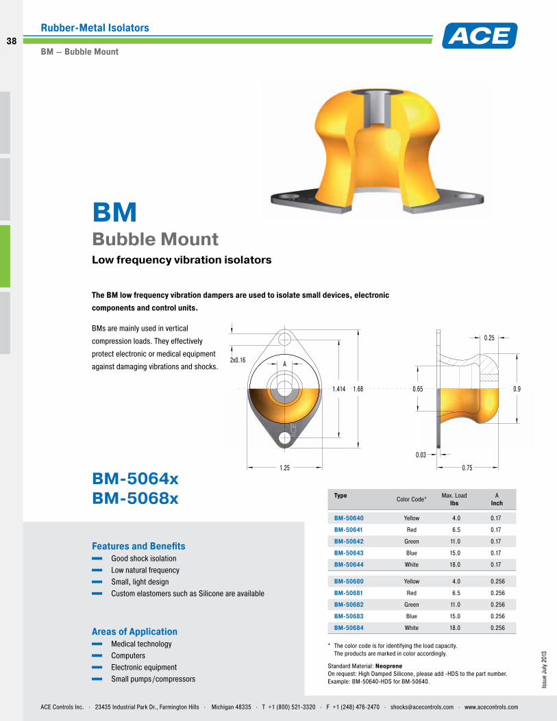
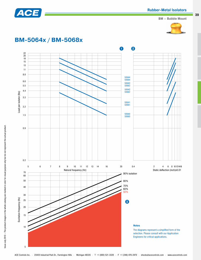
Type Color Code* Max. Load
IbsA
Inch
BM-50640 Yellow 4.0 0.17
BM-50641 Red 6.5 0.17
BM-50642 Green 11.0 0.17
BM-50643 Blue 15.0 0.17
BM-50644 White 18.0 0.17
BM-50680 Yellow 4.0 0.256
BM-50681 Red 6.5 0.256
BM-50682 Green 11.0 0.256
BM-50683 Blue 15.0 0.256
BM-50684 White 18.0 0.256
* The color code is for identifying the load capacity. The products are marked in color accordingly.
Features and Benefits Good shock isolation Low natural frequency Small, light design Custom elastomers such as Silicone are available
Areas of Application Medical technology Computers Electronic equipment Small pumps /compressors
The BM low frequency vibration dampers are used to isolate small devices, electronic components and control units.
BMs are mainly used in vertical
compression loads. They effectively
protect electronic or medical equipment
against damaging vibrations and shocks.
BM Bubble Mount Low frequency vibration isolators
Standard Material: NeopreneOn request: High Damped Silicone, please add -HDS to the part number. Example: BM-50640-HDS for BM-50640.
A
0.25
2x0.16
1.25
1.681.414 0.90.65
0.75
0.03
BM-5064x BM-5068x
ACE Controls Inc. . 23435 Industrial Park Dr., Farmington Hills . Michigan 48335 . T +1 (800) 521-3320 . F +1 (248) 476-2470 . [email protected] . www.acecontrols.com
Rubber-Metal Isolators
BM – Bubble Mount
38
38
0.2
6070
50
40
30
25
20
15
10
5
0.9
1.5
2.2
3.3
4.4
5.5
6.6
8.8
11
15
13
182022
5 7 8 9 10 11 12 13 14 16 206
5064050680
5064150681
5064250682
5064350683
5064450684
50%60%70%
80%
90% isolation
2 4 6 8 101214160.4
Natural frequency (Hz)
Load
per
isol
ator
(lbs
)
Static deflection (inch)x0.01
Exci
tatio
n fre
quen
cy (H
z)
NotesThe diagrams represent a simplified form of the selection. Please consult with our Application Engineers for critical applications.
1 2
3
Issu
e Ju
ly 2
013
– Th
e pr
oduc
t im
ages
in th
e wh
ole
cata
log
are
mar
ked
in c
olor
for v
isua
l pur
pose
onl
y bu
t do
not r
epre
sent
the
actu
al p
rodu
ct.
BM-5064x / BM-5068x
ACE Controls Inc. . 23435 Industrial Park Dr., Farmington Hills . Michigan 48335 . T +1 (800) 521-3320 . F +1 (248) 476-2470 . [email protected] . www.acecontrols.com
Rubber-Metal Isolators
BM – Bubble Mount39
Issu
e Ju
ly 2
013
Features and Benefits Any installation position, all axes and angles Simple design Fail-safe with the use of stop washers Oil, fuel and solvent-resistant neoprene Special design with high-damping silicone available
Areas of Application Machinery and equipment Conveyors Compressors Generators Shipbuilding Construction machines Agricultural machines Off-road vehicles Transport industry
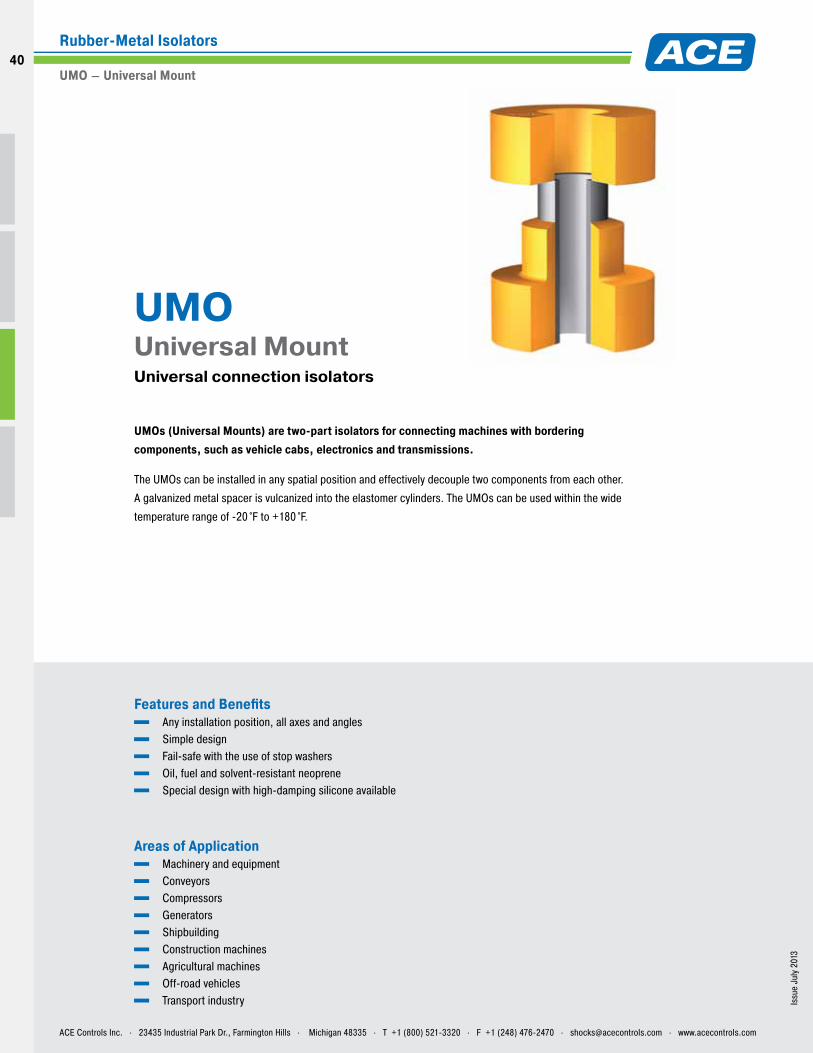
UMOs (Universal Mounts) are two-part isolators for connecting machines with bordering components, such as vehicle cabs, electronics and transmissions.
The UMOs can be installed in any spatial position and effectively decouple two components from each other.
A galvanized metal spacer is vulcanized into the elastomer cylinders. The UMOs can be used within the wide
temperature range of -20 °F to +180 °F.
UMO Universal Mount Universal connection isolators
ACE Controls Inc. . 23435 Industrial Park Dr., Farmington Hills . Michigan 48335 . T +1 (800) 521-3320 . F +1 (248) 476-2470 . [email protected] . www.acecontrols.com
Rubber-Metal Isolators
UMO – Universal Mount
40
40
Issu
e Ju
ly 2
013
– Th
e pr
oduc
t im
ages
in th
e wh
ole
cata
log
are
mar
ked
in c
olor
for v
isua
l pur
pose
onl
y bu
t do
not r
epre
sent
the
actu
al p
rodu
ct.
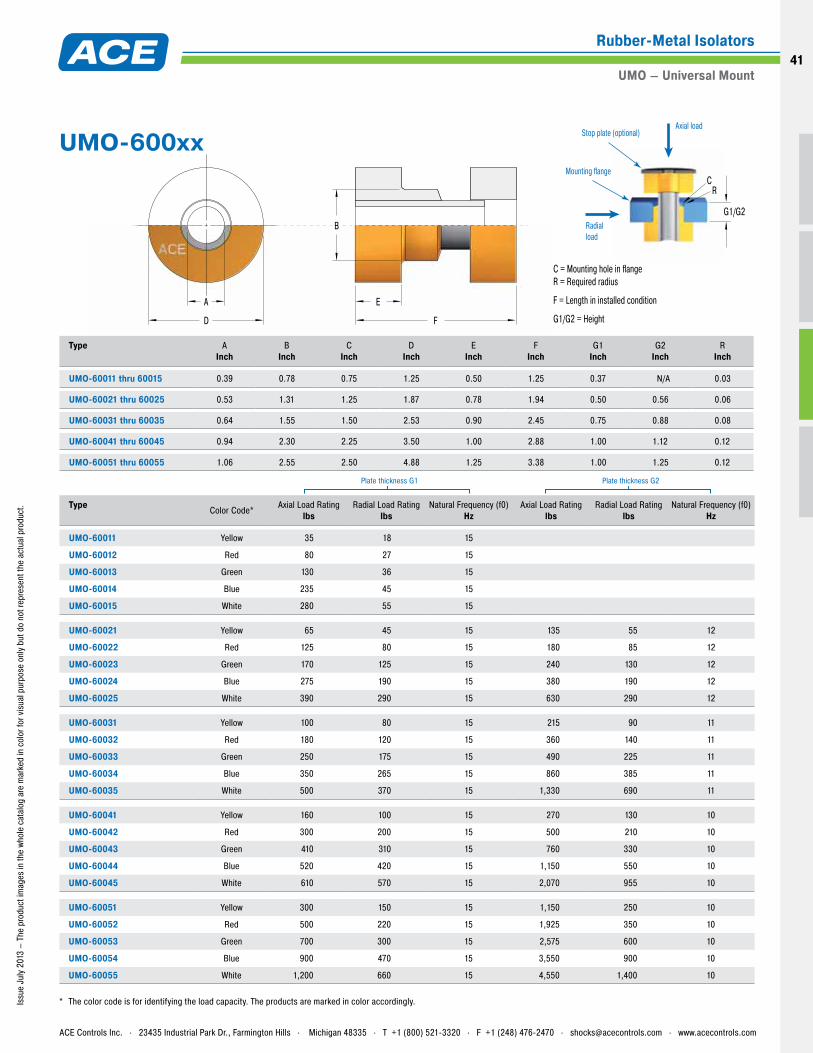
A
D
E
F
C = Mounting hole in flangeR = Required radius
F = Length in installed condition
G1/G2 = Height
Axial loadStop plate (optional)
Radial load
BG1/G2
Mounting flange
RC
Type
AInch
BInch
CInch
DInch
EInch
FInch
G1Inch
G2Inch
RInch
UMO-60011 thru 60015 0.39 0.78 0.75 1.25 0.50 1.25 0.37 N/A 0.03
UMO-60021 thru 60025 0.53 1.31 1.25 1.87 0.78 1.94 0.50 0.56 0.06
UMO-60031 thru 60035 0.64 1.55 1.50 2.53 0.90 2.45 0.75 0.88 0.08
UMO-60041 thru 60045 0.94 2.30 2.25 3.50 1.00 2.88 1.00 1.12 0.12
UMO-60051 thru 60055 1.06 2.55 2.50 4.88 1.25 3.38 1.00 1.25 0.12
Type Color Code* Axial Load Rating
lbsRadial Load Rating
lbsNatural Frequency (f0)
HzAxial Load Rating
lbsRadial Load Rating
lbsNatural Frequency (f0)
Hz
UMO-60011 Yellow 35 18 15
UMO-60012 Red 80 27 15
UMO-60013 Green 130 36 15
UMO-60014 Blue 235 45 15
UMO-60015 White 280 55 15
UMO-60021 Yellow 65 45 15 135 55 12
UMO-60022 Red 125 80 15 180 85 12
UMO-60023 Green 170 125 15 240 130 12
UMO-60024 Blue 275 190 15 380 190 12
UMO-60025 White 390 290 15 630 290 12
UMO-60031 Yellow 100 80 15 215 90 11
UMO-60032 Red 180 120 15 360 140 11
UMO-60033 Green 250 175 15 490 225 11
UMO-60034 Blue 350 265 15 860 385 11
UMO-60035 White 500 370 15 1,330 690 11
UMO-60041 Yellow 160 100 15 270 130 10
UMO-60042 Red 300 200 15 500 210 10
UMO-60043 Green 410 310 15 760 330 10
UMO-60044 Blue 520 420 15 1,150 550 10
UMO-60045 White 610 570 15 2,070 955 10
UMO-60051 Yellow 300 150 15 1,150 250 10
UMO-60052 Red 500 220 15 1,925 350 10
UMO-60053 Green 700 300 15 2,575 600 10
UMO-60054 Blue 900 470 15 3,550 900 10
UMO-60055 White 1,200 660 15 4,550 1,400 10
* The color code is for identifying the load capacity. The products are marked in color accordingly.
Plate thickness G1 Plate thickness G2
UMO-600xx
ACE Controls Inc. . 23435 Industrial Park Dr., Farmington Hills . Michigan 48335 . T +1 (800) 521-3320 . F +1 (248) 476-2470 . [email protected] . www.acecontrols.com
Rubber-Metal Isolators
UMO – Universal Mount41
Issu
e Ju
ly 2
013
Features and Benefits Easy handling Effective decoupling of housings No special tools necessary Isolates structure-borne noise Fail-safe Resistant to oil, most acids and ozone
Areas of Application Machines and assemblies Tiling, sheets and flanges Building attachments Vehicles and transport industry Construction machines
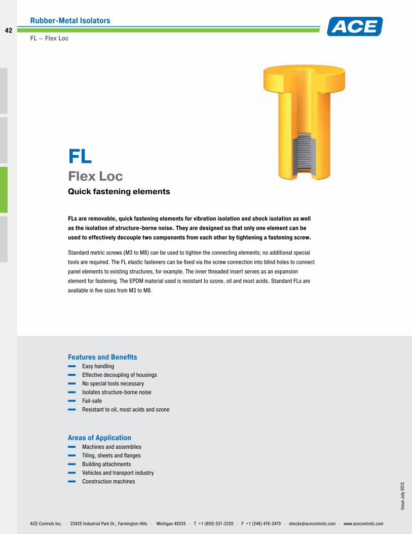
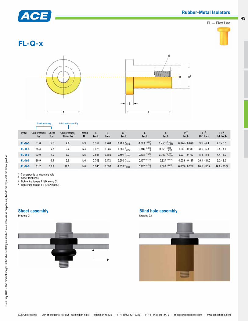
FLs are removable, quick fastening elements for vibration isolation and shock isolation as well as the isolation of structure-borne noise. They are designed so that only one element can be used to effectively decouple two components from each other by tightening a fastening screw.
Standard metric screws (M3 to M8) can be used to tighten the connecting elements; no additional special
tools are required. The FL elastic fasteners can be fixed via the screw connection into blind holes to connect
panel elements to existing structures, for example. The inner threaded insert serves as an expansion
element for fastening. The EPDM material used is resistant to ozone, oil and most acids. Standard FLs are
available in five sizes from M3 to M8.
FL Flex Loc Quick fastening elements
ACE Controls Inc. . 23435 Industrial Park Dr., Farmington Hills . Michigan 48335 . T +1 (800) 521-3320 . F +1 (248) 476-2470 . [email protected] . www.acecontrols.com
Rubber-Metal Isolators
FL – Flex Loc
42
42
Issu
e Ju
ly 2
013
– Th
e pr
oduc
t im
ages
in th
e wh
ole
cata
log
are
mar
ked
in c
olor
for v
isua
l pur
pose
onl
y bu
t do
not r
epre
sent
the
actu
al p
rodu
ct.
A
E
L
B
M
C1
Type
CompressionIbs
ShearIbs
Compression/Shear Ibs
ThreadM
AInch
BInch
C 1Inch
EInch
LInch
P 2Inch
T I 3Ibf Inch
T II 4Ibf Inch
FL-Q-3 11.0 5.5 2.2 M3 0.354 0.264 0.283 0–0.012 0.098 +0.0160 0.453 +0.039
–0.020 0.024 - 0.098 3.5 - 4.4 2.7 - 3.5
FL-Q-4 15.4 7.7 2.2 M4 0.472 0.335 0.366 0–0.012 0.118 +0.0160 0.571+0.039
–0.020 0.031 - 0.130 3.5 - 5.3 3.5 - 4.4
FL-Q-5 22.0 11.0 3.3 M5 0.591 0.386 0.401 0–0.012 0.138 +0.0160 0.709 +0.039
–0.020 0.031 - 0.169 5.3 - 8.9 4.4 - 5.3
FL-Q-6 30.9 15.4 6.6 M6 0.709 0.472 0.500 0–0.012 0.157 +0.0160 0.827 ±0.039 0.059 - 0.197 20.4 - 31.0 6.2 - 8.0
FL-Q-8 61.7 30.9 11.0 M8 0.945 0.630 0.650 0–0.020 0.197 +0.0160 1.063 ±0.039 0.059 - 0.256 26.6 - 35.4 14.2 - 15.9
1 Corresponds to mounting hole 2 Sheet thickness 3 Tightening torque T I (Drawing 01) 4 Tightening torque T II (Drawing 02)
Sheet assembly Blind hole assembly
P
FL-Q-x
Sheet assemblyDrawing 01
Blind hole assemblyDrawing 02
ACE Controls Inc. . 23435 Industrial Park Dr., Farmington Hills . Michigan 48335 . T +1 (800) 521-3320 . F +1 (248) 476-2470 . [email protected] . www.acecontrols.com
Rubber-Metal Isolators
FL – Flex Loc43
Vibration-Isolating Pads
02
44
44
Issu
e Ju
ly 2
013
– Th
e pr
oduc
t im
ages
in th
e wh
ole
cata
log
are
mar
ked
in c
olor
for v
isua
l pur
pose
onl
y bu
t do
not r
epre
sent
the
actu
al p
rodu
ct.
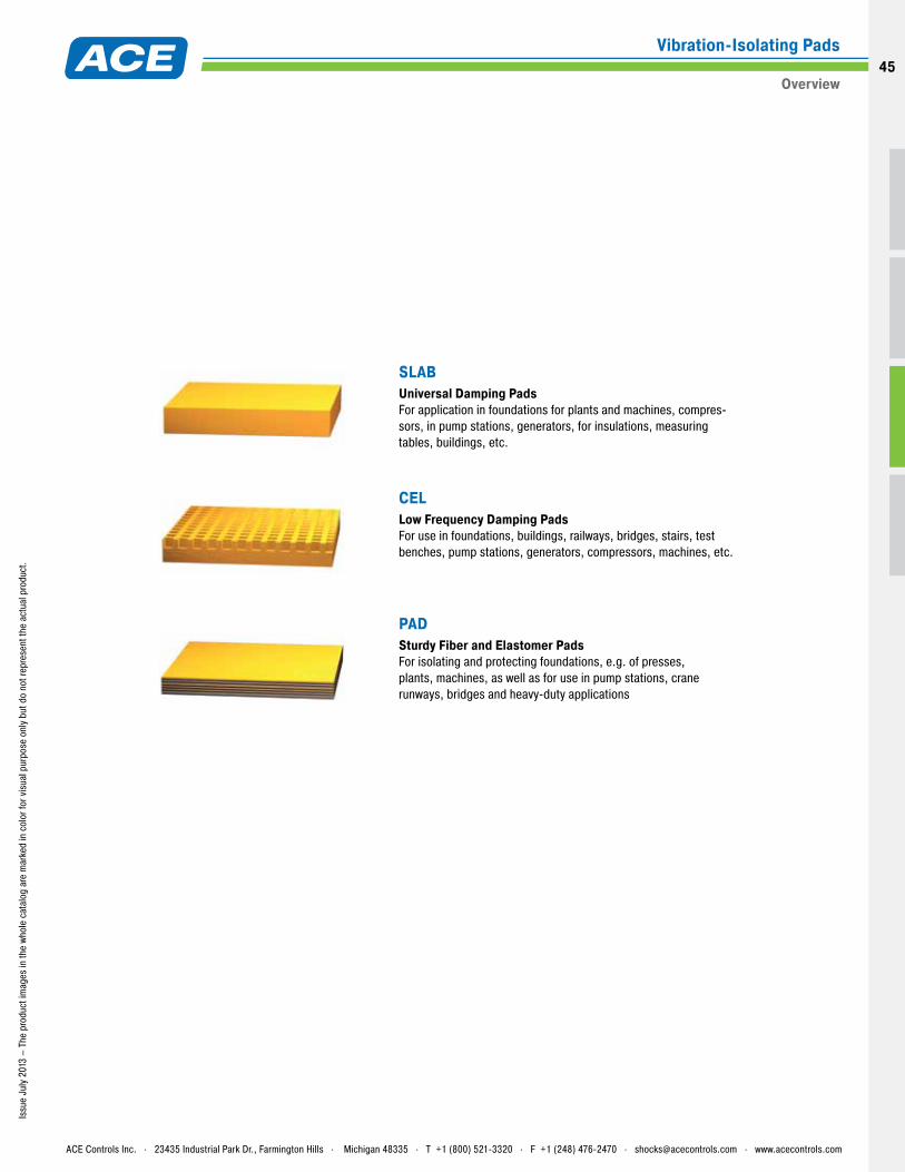
SLABUniversal Damping Pads For application in foundations for plants and machines, compres-sors, in pump stations, generators, for insulations, measuring tables, buildings, etc.
CEL Low Frequency Damping Pads For use in foundations, buildings, railways, bridges, stairs, test benches, pump stations, generators, compressors, machines, etc.
PAD Sturdy Fiber and Elastomer Pads For isolating and protecting foundations, e.g. of presses, plants, machines, as well as for use in pump stations, crane runways, bridges and heavy-duty applications
ACE Controls Inc. . 23435 Industrial Park Dr., Farmington Hills . Michigan 48335 . T +1 (800) 521-3320 . F +1 (248) 476-2470 . [email protected] . www.acecontrols.com
Vibration-Isolating Pads
Overview45
Issu
e Ju
ly 2
013
– Th
e pr
oduc
t im
ages
are
mar
ked
in c
olor
for v
isua
l pur
pose
onl
y bu
t do
not r
epre
sent
the
actu
al p
rodu
ct.
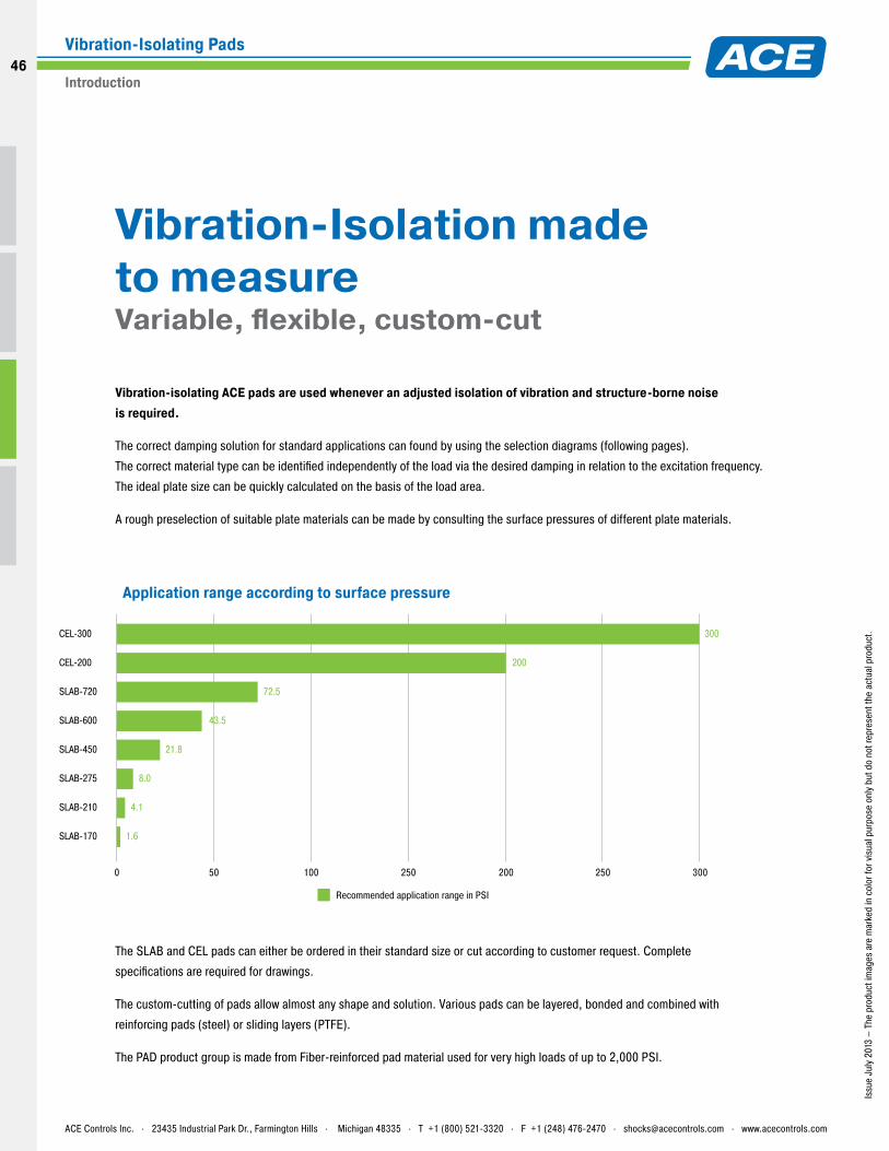
SLAB-720 72.5
CEL-200
CEL-300
200
300
SLAB-600 43.5
SLAB-450 21.8
SLAB-275 8.0
SLAB-210 4.1
SLAB-170 1.6
Recommended application range in PSI
200 30025025050 1000
Vibration-Isolation made to measure Variable, flexible, custom-cut
Vibration-isolating ACE pads are used whenever an adjusted isolation of vibration and structure-borne noise is required.
The correct damping solution for standard applications can found by using the selection diagrams (following pages).
The correct material type can be identified independently of the load via the desired damping in relation to the excitation frequency.
The ideal plate size can be quickly calculated on the basis of the load area.
A rough preselection of suitable plate materials can be made by consulting the surface pressures of different plate materials.
The SLAB and CEL pads can either be ordered in their standard size or cut according to customer request. Complete
specifications are required for drawings.
The custom-cutting of pads allow almost any shape and solution. Various pads can be layered, bonded and combined with
reinforcing pads (steel) or sliding layers (PTFE).
The PAD product group is made from Fiber-reinforced pad material used for very high loads of up to 2,000 PSI.
Application range according to surface pressure
ACE Controls Inc. . 23435 Industrial Park Dr., Farmington Hills . Michigan 48335 . T +1 (800) 521-3320 . F +1 (248) 476-2470 . [email protected] . www.acecontrols.com
Vibration-Isolating Pads
Introduction
46
46
Issu
e Ju
ly 2
013
Features and Benefits Can be cut to many different shapes (water jet cutting) Can be combined for many desired isolation packages On-site vibration measurement and selection ACE offers special application software with no additional costs for designing. Highly damping polyurethane
Areas of Application Foundations of plants and machines Compressors Pump stations and generators Pipeline isolation Test benches, measuring tables and their foundations Buildings Staircase bearings
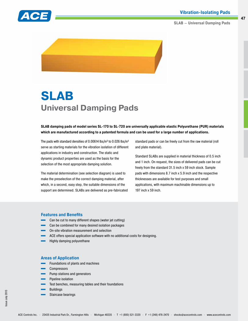
SLAB damping pads of model series SL-170 to SL-720 are universally applicable elastic Polyurethane (PUR) materials which are manufactured according to a patented formula and can be used for a large number of applications.
SLAB Universal Damping Pads
The pads with standard densities of 0.00614 lbs/in³ to 0.026 lbs/in³
serve as starting materials for the vibration isolation of different
applications in industry and construction. The static and
dynamic product properties are used as the basis for the
selection of the most appropriate damping solution.
The material determination (see selection diagram) is used to
make the preselection of the correct damping material, after
which, in a second, easy step, the suitable dimensions of the
support are determined. SLABs are delivered as pre-fabricated
standard pads or can be freely cut from the raw material (roll
and plate material).
Standard SLABs are supplied in material thickness of 0.5 inch
and 1 inch. On request, the sizes of delivered pads can be cut
freely from the standard 31.5 inch x 59 inch stock. Sample
pads with dimensions 8.7 inch x 5.9 inch and the respective
thicknesses are available for test purposes and small
applications, with maximum machinable dimensions up to
197 inch x 59 inch.
ACE Controls Inc. . 23435 Industrial Park Dr., Farmington Hills . Michigan 48335 . T +1 (800) 521-3320 . F +1 (248) 476-2470 . [email protected] . www.acecontrols.com
Vibration-Isolating Pads
SLAB – Universal Damping Pads47
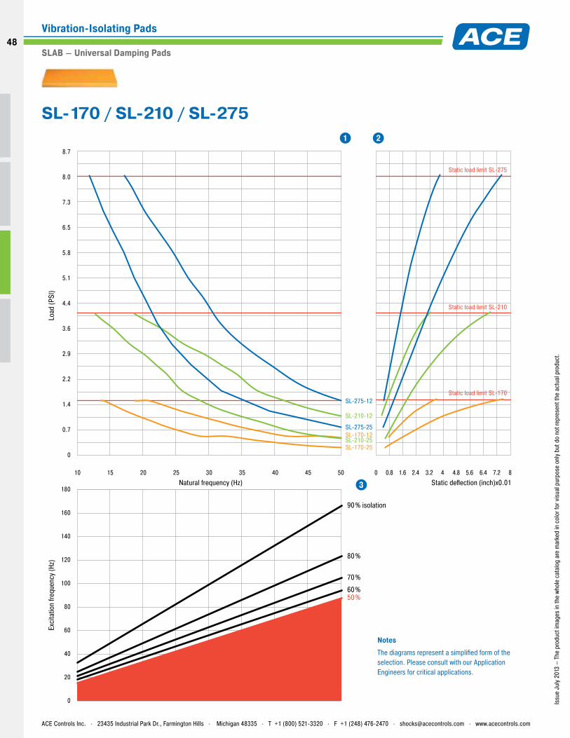
180
0
40
20
80
120
160
60
100
140
10 2015 25 30 454035 50 1.60.8 2.4 3.2 4 4.8 5.6 6.4 7.2 80
Load
(PSI
)
Natural frequency (Hz)
50%60%
70%
80%
90% isolation
SL-275-25
SL-210-12
SL-210-25SL-170-25
SL-170-12
SL-275-12
Static load limit SL-275
Static load limit SL-210
Static load limit SL-170
Static deflection (inch)x0.01
Exci
tatio
n fre
quen
cy (H
z)
0
2.9
5.1
6.5
7.3
8.0
5.8
4.4
3.6
0.7
2.2
1.4
8.7
NotesThe diagrams represent a simplified form of the selection. Please consult with our Application Engineers for critical applications.
1 2
3
Issu
e Ju
ly 2
013
– Th
e pr
oduc
t im
ages
in th
e wh
ole
cata
log
are
mar
ked
in c
olor
for v
isua
l pur
pose
onl
y bu
t do
not r
epre
sent
the
actu
al p
rodu
ct.
SL-170 / SL-210 / SL-275
ACE Controls Inc. . 23435 Industrial Park Dr., Farmington Hills . Michigan 48335 . T +1 (800) 521-3320 . F +1 (248) 476-2470 . [email protected] . www.acecontrols.com
Vibration-Isolating Pads
SLAB – Universal Damping Pads
48
48
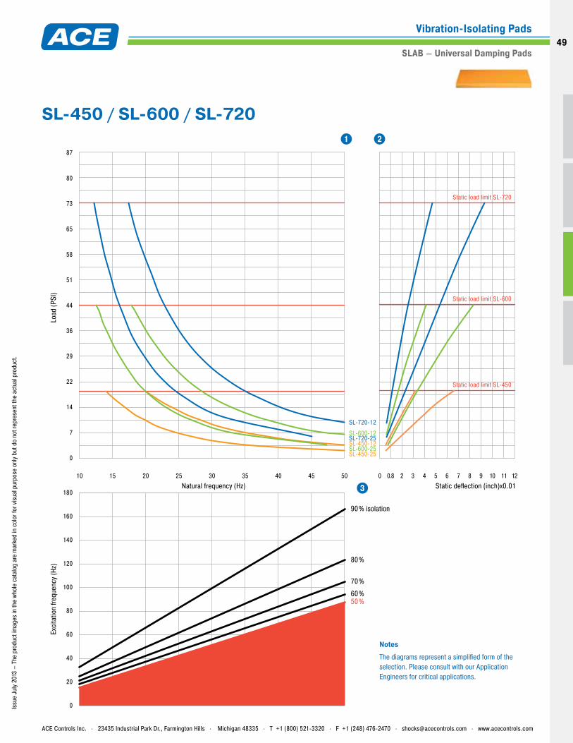
180
0
40
20
80
120
160
60
100
140
10 2015 25 30 454035 50 0.8 2 3 4 5 6 7 8 9 10 11 12
0
Load
(PSI
)
Natural frequency (Hz)
50%60%
70%
80%
90% isolation
SL-720-25SL-600-12
SL-600-25SL-450-25
SL-450-12
SL-720-12
Static load limit SL-720
Static load limit SL-600
Static load limit SL-450
Static deflection (inch)x0.01
Exci
tatio
n fre
quen
cy (H
z)
0
29
51
65
73
80
58
44
36
7
22
14
87
NotesThe diagrams represent a simplified form of the selection. Please consult with our Application Engineers for critical applications.
1 2
3
Issu
e Ju
ly 2
013
– Th
e pr
oduc
t im
ages
in th
e wh
ole
cata
log
are
mar
ked
in c
olor
for v
isua
l pur
pose
onl
y bu
t do
not r
epre
sent
the
actu
al p
rodu
ct.
SL-450 / SL-600 / SL-720
ACE Controls Inc. . 23435 Industrial Park Dr., Farmington Hills . Michigan 48335 . T +1 (800) 521-3320 . F +1 (248) 476-2470 . [email protected] . www.acecontrols.com
Vibration-Isolating Pads
SLAB – Universal Damping Pads49
Issu
e Ju
ly 2
013
Features and Benefits Can be bonded together (layered) to form desired isolation efficiency ACE offers on-site vibration measurement and selection ACE offers special application software with no additional costs for designing
Areas of Application Foundations of plants and machines Compressors Pump stations and generators Pipeline isolation Test benches, measuring tables and their foundations Buildings Transport routes, bridges Staircase bearings
CEL damping pads are produced from a special nitrile rubber which dampens at low-frequencies.
The damping pads can be custom-cut and bonded together to achieve the proper thickness
based on the application and isolation requirement. The tried-and-tested CEL damping pads
are used in the field of machine and plant engineering. Here the pads isolate the floor or
foundation to the plant or machine. Damaging vibrations are reduced, increasing production
and or measuring quality.
CEL Low Frequency Damping Pads
ACE Controls Inc. . 23435 Industrial Park Dr., Farmington Hills . Michigan 48335 . T +1 (800) 521-3320 . F +1 (248) 476-2470 . [email protected] . www.acecontrols.com
Vibration-Isolating Pads
CEL – Low Frequency Damping Pads
50
50
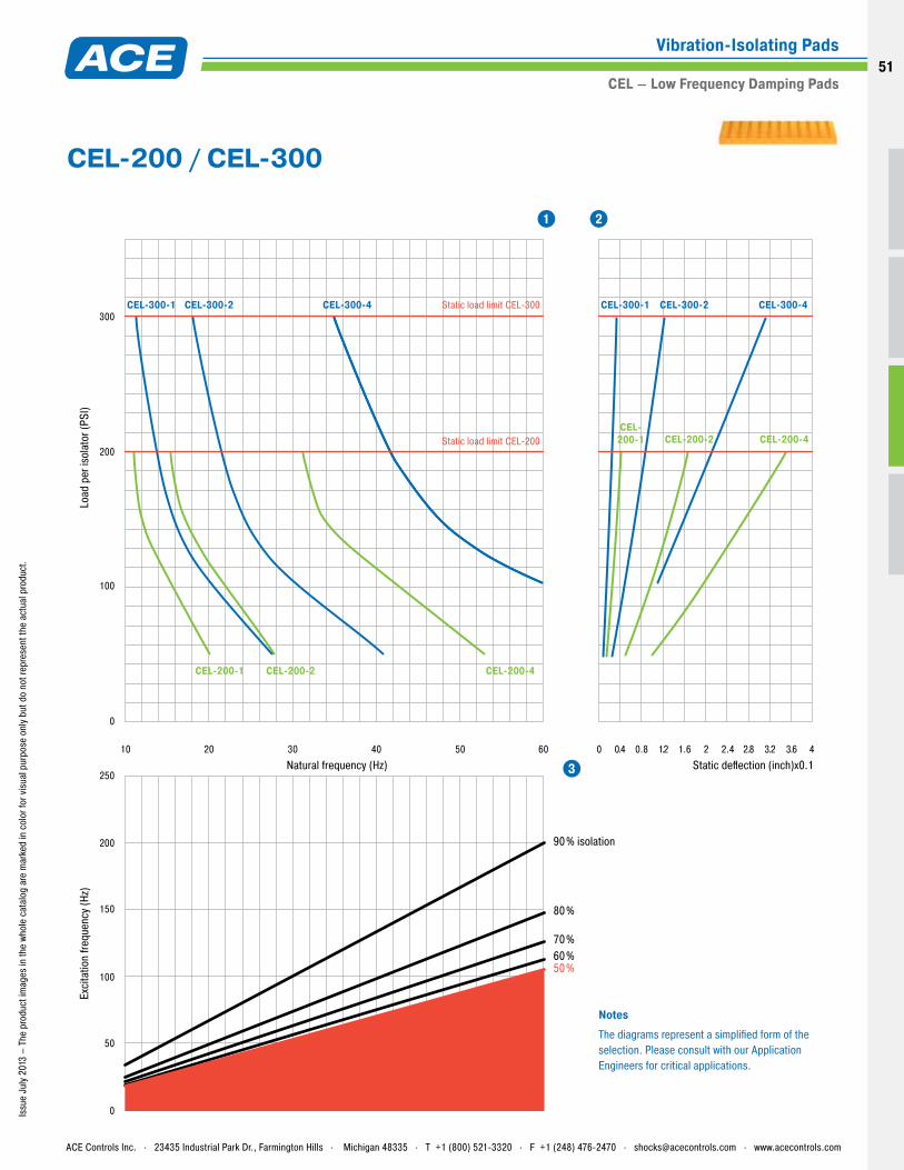
0
250
0
50
100
150
200
100
200
300
10 20 30 40 50 60 0.4 0.8 1.2 1.6 2 2.4 2.8 3.2 3.6 4
0
CEL-200-1 CEL-200-2 CEL-200-4
CEL-300-1 CEL-300-2 CEL-300-4 Static load limit CEL-300
Static load limit CEL-200CEL-
200-1 CEL-200-2 CEL-200-4
CEL-300-1 CEL-300-2 CEL-300-4
Load
per
isol
ator
(PSI
)
Natural frequency (Hz)
50%60%70%
80%
90% isolation
Static deflection (inch)x0.1
Exci
tatio
n fre
quen
cy (H
z)
NotesThe diagrams represent a simplified form of the selection. Please consult with our Application Engineers for critical applications.
1 2
3
Issu
e Ju
ly 2
013
– Th
e pr
oduc
t im
ages
in th
e wh
ole
cata
log
are
mar
ked
in c
olor
for v
isua
l pur
pose
onl
y bu
t do
not r
epre
sent
the
actu
al p
rodu
ct.
CEL-200 / CEL-300
ACE Controls Inc. . 23435 Industrial Park Dr., Farmington Hills . Michigan 48335 . T +1 (800) 521-3320 . F +1 (248) 476-2470 . [email protected] . www.acecontrols.com
Vibration-Isolating Pads
CEL – Low Frequency Damping Pads51
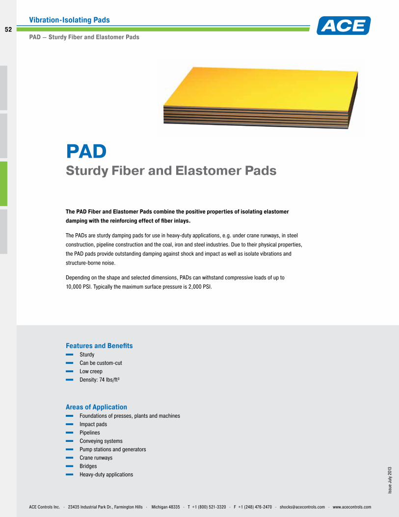
Issu
e Ju
ly 2
013
Features and Benefits Sturdy Can be custom-cut Low creep Density: 74 lbs/ft³
Areas of Application Foundations of presses, plants and machines Impact pads Pipelines Conveying systems Pump stations and generators Crane runways Bridges Heavy-duty applications
The PAD Fiber and Elastomer Pads combine the positive properties of isolating elastomer damping with the reinforcing effect of fiber inlays.
The PADs are sturdy damping pads for use in heavy-duty applications, e.g. under crane runways, in steel
construction, pipeline construction and the coal, iron and steel industries. Due to their physical properties,
the PAD pads provide outstanding damping against shock and impact as well as isolate vibrations and
structure-borne noise.
Depending on the shape and selected dimensions, PADs can withstand compressive loads of up to
10,000 PSI. Typically the maximum surface pressure is 2,000 PSI.
PAD Sturdy Fiber and Elastomer Pads
ACE Controls Inc. . 23435 Industrial Park Dr., Farmington Hills . Michigan 48335 . T +1 (800) 521-3320 . F +1 (248) 476-2470 . [email protected] . www.acecontrols.com
Vibration-Isolating Pads
PAD – Sturdy Fiber and Elastomer Pads
52
52
Issu
e Ju
ly 2
013
– Th
e pr
oduc
t im
ages
in th
e wh
ole
cata
log
are
mar
ked
in c
olor
for v
isua
l pur
pose
onl
y bu
t do
not r
epre
sent
the
actu
al p
rodu
ct.
Due to the layered structure, the material exhibits excellent compressibility.
This allows deflection to be reached without material flow (custom-fit installation
to specific dimensions is possible). The material properties are also apparent in
the creep behavior under load. For example, under continuous static load, the
material only exhibits a creep tendency of approximately 5% of original
thickness.
Depending on the application, the PADs can be custom cut to meet customer
specifications and/or be used as supports, washers and bushings with an
isolating/damping effect.
Selection and calculation
As with a conventional shock isolation application, the selection of
a suitable material is based on the consideration of the kinetic
energy in the system in relation to the desired damping value. The
hysteresis curve for the material is then taken as the basis for
selecting the correct material dimensions.
To measure the Kinetic Energy (KE), you may use the shock
absorber calculation software which is offered at
www.acecontrols.com free of charge. You can enter your values
and obtain a suitable KE result.
Our in-house and field teams are available to assist you.
Note
PADs consist of organic material subject to batch-based variations
PADs meet the following military specifications: MIL-C-882 and MIL-E-5272A.
The PADs are resistant to most oils, water vapor, water, mold and brine. Operating temperature range is between -65 °F and 200 °F.
The hardness of PADs is 90 ±5 shore A.
The standard pads are available in different thicknesses, graduated between 1/16" and 1". Other thicknesses are available by combining and bonding the standard thicknesses.
A combination with steel or PTFE pads is also available upon request.
ACE Controls Inc. . 23435 Industrial Park Dr., Farmington Hills . Michigan 48335 . T +1 (800) 521-3320 . F +1 (248) 476-2470 . [email protected] . www.acecontrols.com
Vibration-Isolating Pads
PAD – Sturdy Fiber and Elastomer Pads53
03Low Frequency Pneumatic Leveling Mounts
54
54
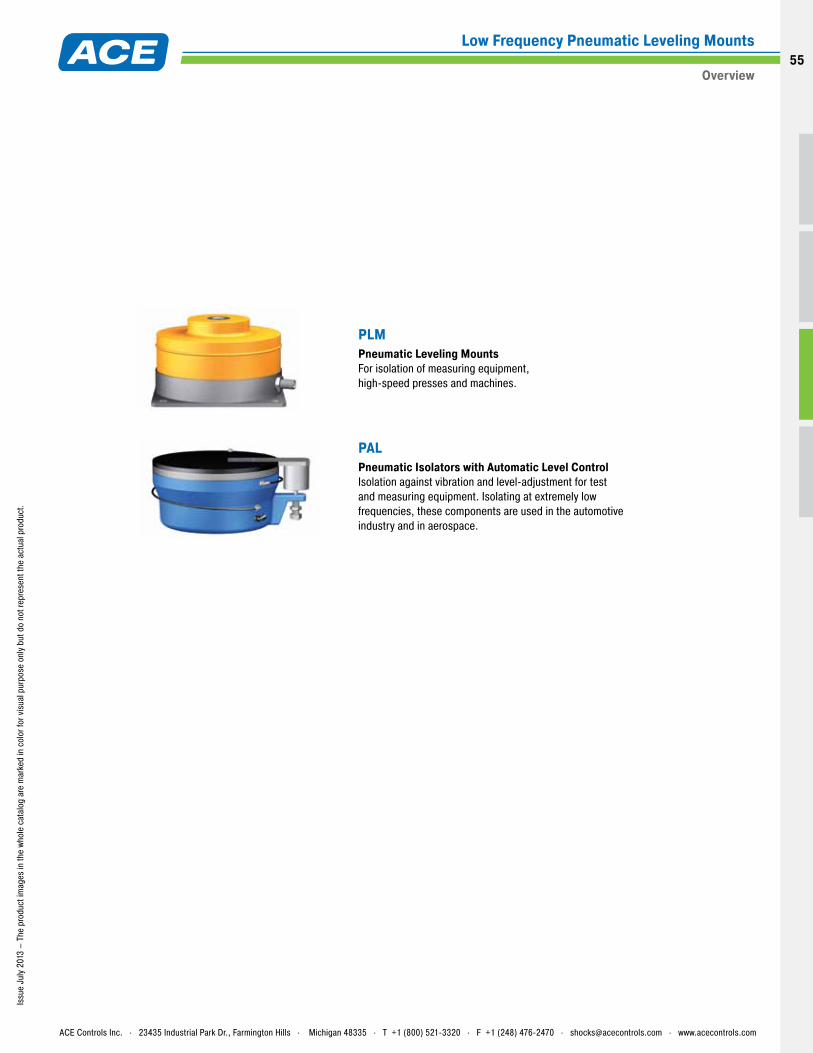
Issu
e Ju
ly 2
013
– Th
e pr
oduc
t im
ages
in th
e wh
ole
cata
log
are
mar
ked
in c
olor
for v
isua
l pur
pose
onl
y bu
t do
not r
epre
sent
the
actu
al p
rodu
ct.
PLMPneumatic Leveling Mounts For isolation of measuring equipment, high-speed presses and machines.
PAL Pneumatic Isolators with Automatic Level Control Isolation against vibration and level-adjustment for test and measuring equipment. Isolating at extremely low frequencies, these components are used in the automotive industry and in aerospace.
ACE Controls Inc. . 23435 Industrial Park Dr., Farmington Hills . Michigan 48335 . T +1 (800) 521-3320 . F +1 (248) 476-2470 . [email protected] . www.acecontrols.com
Low Frequency Pneumatic Leveling Mounts
Overview55
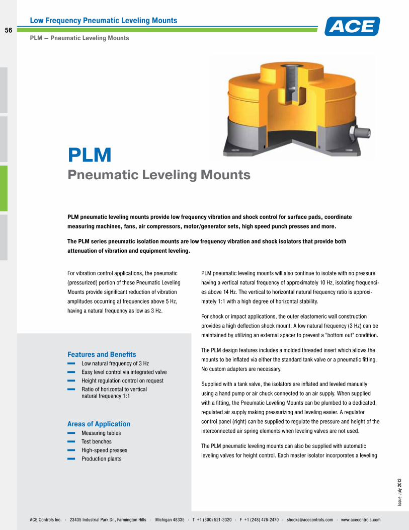
Issu
e Ju
ly 2
013
For vibration control applications, the pneumatic
(pressurized) portion of these Pneumatic Leveling
Mounts provide significant reduction of vibration
amplitudes occurring at frequencies above 5 Hz,
having a natural frequency as low as 3 Hz.
Features and Benefits Low natural frequency of 3 Hz Easy level control via integrated valve Height regulation control on request Ratio of horizontal to vertical
natural frequency 1:1
Areas of Application Measuring tables Test benches High-speed presses Production plants
PLM pneumatic leveling mounts provide low frequency vibration and shock control for surface pads, coordinate measuring machines, fans, air compressors, motor/generator sets, high speed punch presses and more.
The PLM series pneumatic isolation mounts are low frequency vibration and shock isolators that provide both attenuation of vibration and equipment leveling.
PLM Pneumatic Leveling Mounts
PLM pneumatic leveling mounts will also continue to isolate with no pressure
having a vertical natural frequency of approximately 10 Hz, isolating frequenci-
es above 14 Hz. The vertical to horizontal natural frequency ratio is approxi-
mately 1:1 with a high degree of horizontal stability.
For shock or impact applications, the outer elastomeric wall construction
provides a high deflection shock mount. A low natural frequency (3 Hz) can be
maintained by utilizing an external spacer to prevent a “bottom out” condition.
The PLM design features includes a molded threaded insert which allows the
mounts to be inflated via either the standard tank valve or a pneumatic fitting.
No custom adapters are necessary.
Supplied with a tank valve, the isolators are inflated and leveled manually
using a hand pump or air chuck connected to an air supply. When supplied
with a fitting, the Pneumatic Leveling Mounts can be plumbed to a dedicated,
regulated air supply making pressurizing and leveling easier. A regulator
control panel (right) can be supplied to regulate the pressure and height of the
interconnected air spring elements when leveling valves are not used.
The PLM pneumatic leveling mounts can also be supplied with automatic
leveling valves for height control. Each master isolator incorporates a leveling
ACE Controls Inc. . 23435 Industrial Park Dr., Farmington Hills . Michigan 48335 . T +1 (800) 521-3320 . F +1 (248) 476-2470 . [email protected] . www.acecontrols.com
Low Frequency Pneumatic Leveling Mounts
PLM – Pneumatic Leveling Mounts
56
56
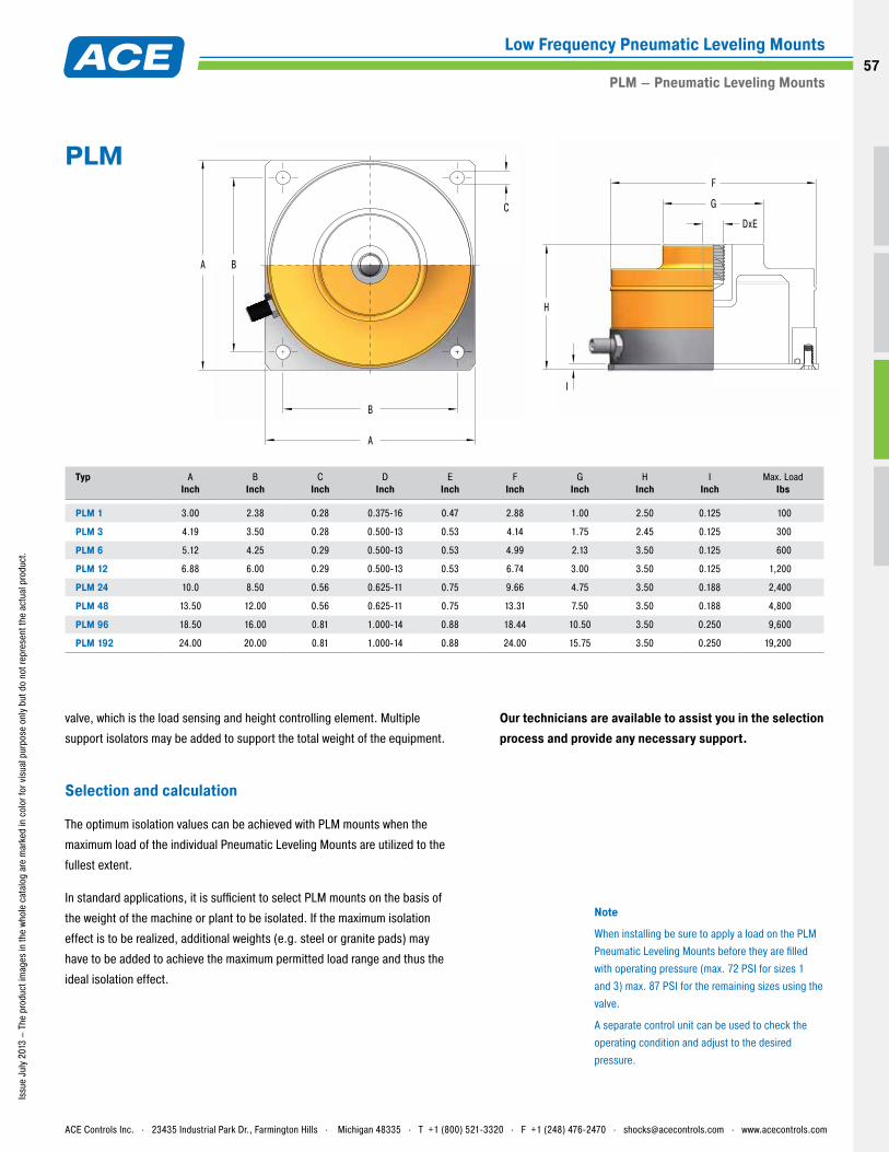
Issu
e Ju
ly 2
013
– Th
e pr
oduc
t im
ages
in th
e wh
ole
cata
log
are
mar
ked
in c
olor
for v
isua
l pur
pose
onl
y bu
t do
not r
epre
sent
the
actu
al p
rodu
ct.
A
B
A B
H
I
G
DxE
F
C
Typ
A Inch
B Inch
CInch
D Inch
EInch
FInch
GInch
HInch
IInch
Max. LoadIbs
PLM 1 3.00 2.38 0.28 0.375-16 0.47 2.88 1.00 2.50 0.125 100
PLM 3 4.19 3.50 0.28 0.500-13 0.53 4.14 1.75 2.45 0.125 300
PLM 6 5.12 4.25 0.29 0.500-13 0.53 4.99 2.13 3.50 0.125 600
PLM 12 6.88 6.00 0.29 0.500-13 0.53 6.74 3.00 3.50 0.125 1,200
PLM 24 10.0 8.50 0.56 0.625-11 0.75 9.66 4.75 3.50 0.188 2,400
PLM 48 13.50 12.00 0.56 0.625-11 0.75 13.31 7.50 3.50 0.188 4,800
PLM 96 18.50 16.00 0.81 1.000-14 0.88 18.44 10.50 3.50 0.250 9,600
PLM 192 24.00 20.00 0.81 1.000-14 0.88 24.00 15.75 3.50 0.250 19,200
PLM
Note
When installing be sure to apply a load on the PLM Pneumatic Leveling Mounts before they are filled with operating pressure (max. 72 PSI for sizes 1 and 3) max. 87 PSI for the remaining sizes using the valve.
A separate control unit can be used to check the operating condition and adjust to the desired pressure.
valve, which is the load sensing and height controlling element. Multiple
support isolators may be added to support the total weight of the equipment.
Selection and calculation
The optimum isolation values can be achieved with PLM mounts when the
maximum load of the individual Pneumatic Leveling Mounts are utilized to the
fullest extent.
In standard applications, it is sufficient to select PLM mounts on the basis of
the weight of the machine or plant to be isolated. If the maximum isolation
effect is to be realized, additional weights (e.g. steel or granite pads) may
have to be added to achieve the maximum permitted load range and thus the
ideal isolation effect.
Our technicians are available to assist you in the selection process and provide any necessary support.
ACE Controls Inc. . 23435 Industrial Park Dr., Farmington Hills . Michigan 48335 . T +1 (800) 521-3320 . F +1 (248) 476-2470 . [email protected] . www.acecontrols.com
Low Frequency Pneumatic Leveling Mounts
PLM – Pneumatic Leveling Mounts57
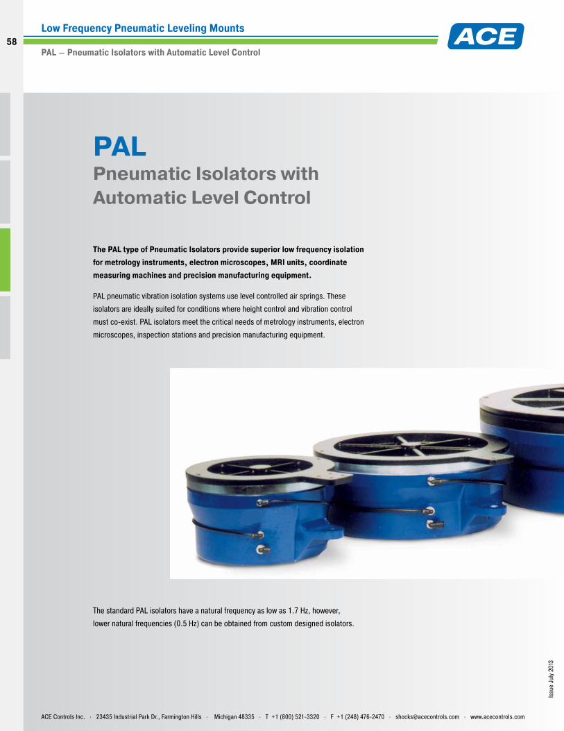
Issu
e Ju
ly 2
013
PAL Pneumatic Isolators with Automatic Level Control
The PAL type of Pneumatic Isolators provide superior low frequency isolation for metrology instruments, electron microscopes, MRI units, coordinate measuring machines and precision manufacturing equipment.
PAL pneumatic vibration isolation systems use level controlled air springs. These
isolators are ideally suited for conditions where height control and vibration control
must co-exist. PAL isolators meet the critical needs of metrology instruments, electron
microscopes, inspection stations and precision manufacturing equipment.
The standard PAL isolators have a natural frequency as low as 1.7 Hz, however,
lower natural frequencies (0.5 Hz) can be obtained from custom designed isolators.
ACE Controls Inc. . 23435 Industrial Park Dr., Farmington Hills . Michigan 48335 . T +1 (800) 521-3320 . F +1 (248) 476-2470 . [email protected] . www.acecontrols.com
Low Frequency Pneumatic Leveling Mounts
PAL – Pneumatic Isolators with Automatic Level Control
58
58
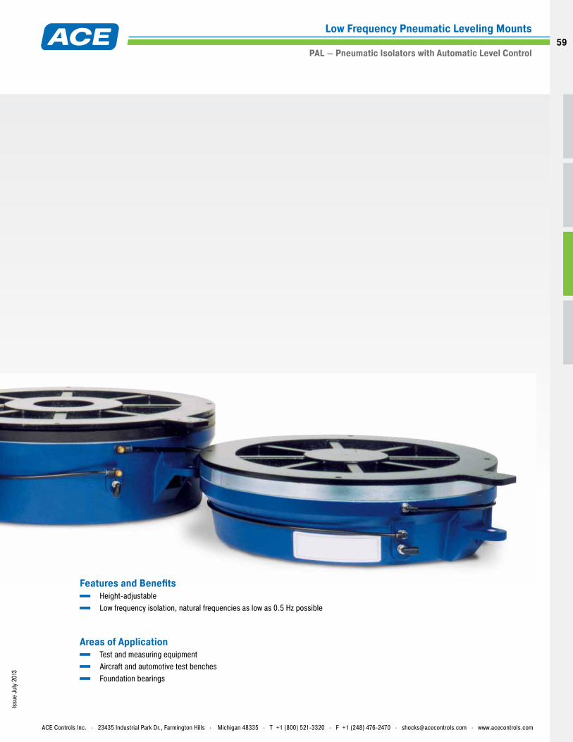
Issu
e Ju
ly 2
013
Features and Benefits Height-adjustable Low frequency isolation, natural frequencies as low as 0.5 Hz possible
Areas of Application Test and measuring equipment Aircraft and automotive test benches Foundation bearings
ACE Controls Inc. . 23435 Industrial Park Dr., Farmington Hills . Michigan 48335 . T +1 (800) 521-3320 . F +1 (248) 476-2470 . [email protected] . www.acecontrols.com
Low Frequency Pneumatic Leveling Mounts
PAL – Pneumatic Isolators with Automatic Level Control59
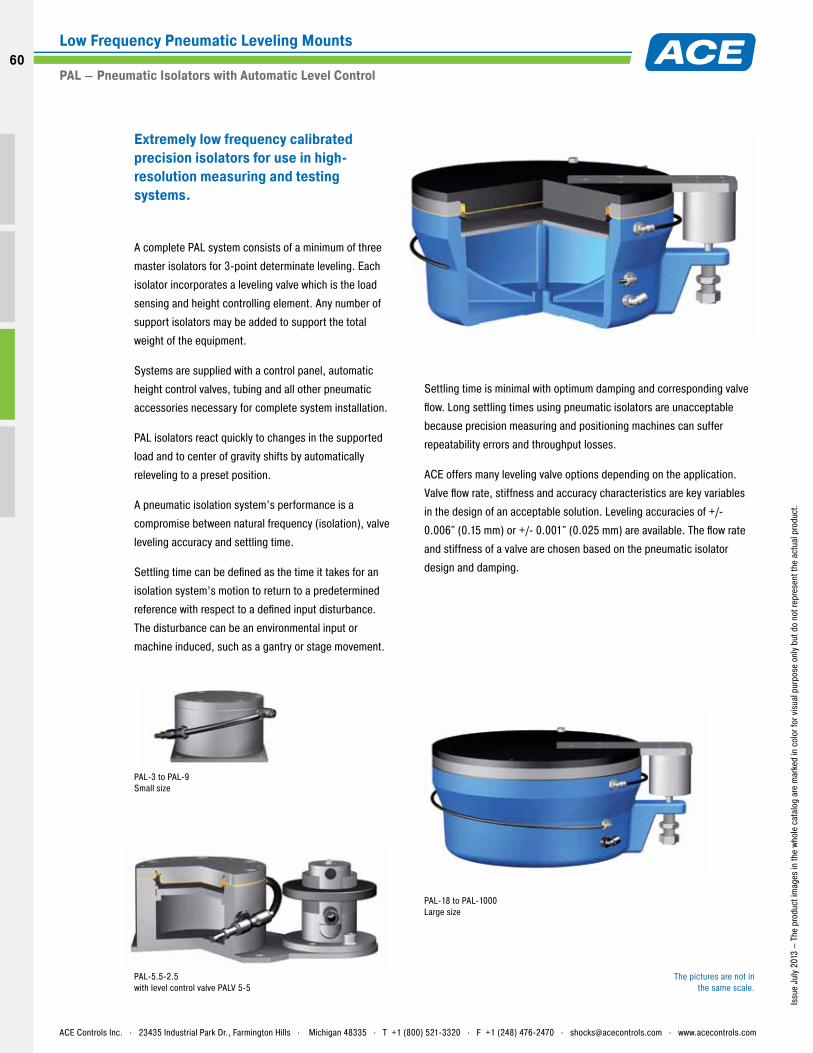
Issu
e Ju
ly 2
013
– Th
e pr
oduc
t im
ages
in th
e wh
ole
cata
log
are
mar
ked
in c
olor
for v
isua
l pur
pose
onl
y bu
t do
not r
epre
sent
the
actu
al p
rodu
ct.
A complete PAL system consists of a minimum of three
master isolators for 3-point determinate leveling. Each
isolator incorporates a leveling valve which is the load
sensing and height controlling element. Any number of
support isolators may be added to support the total
weight of the equipment.
Systems are supplied with a control panel, automatic
height control valves, tubing and all other pneumatic
accessories necessary for complete system installation.
PAL isolators react quickly to changes in the supported
load and to center of gravity shifts by automatically
releveling to a preset position.
A pneumatic isolation system’s performance is a
compromise between natural frequency (isolation), valve
leveling accuracy and settling time.
Settling time can be defined as the time it takes for an
isolation system’s motion to return to a predetermined
reference with respect to a defined input disturbance.
The disturbance can be an environmental input or
machine induced, such as a gantry or stage movement.
Settling time is minimal with optimum damping and corresponding valve
flow. Long settling times using pneumatic isolators are unacceptable
because precision measuring and positioning machines can suffer
repeatability errors and throughput losses.
ACE offers many leveling valve options depending on the application.
Valve flow rate, stiffness and accuracy characteristics are key variables
in the design of an acceptable solution. Leveling accuracies of +/-
0.006" (0.15 mm) or +/- 0.001" (0.025 mm) are available. The flow rate
and stiffness of a valve are chosen based on the pneumatic isolator
design and damping.
Extremely low frequency calibrated precision isolators for use in high-resolution measuring and testing systems.
PAL-18 to PAL-1000 Large size
PAL-3 to PAL-9 Small size
PAL-5.5-2.5 with level control valve PALV 5-5
The pictures are not in the same scale.
ACE Controls Inc. . 23435 Industrial Park Dr., Farmington Hills . Michigan 48335 . T +1 (800) 521-3320 . F +1 (248) 476-2470 . [email protected] . www.acecontrols.com
Low Frequency Pneumatic Leveling Mounts
PAL – Pneumatic Isolators with Automatic Level Control
60
60
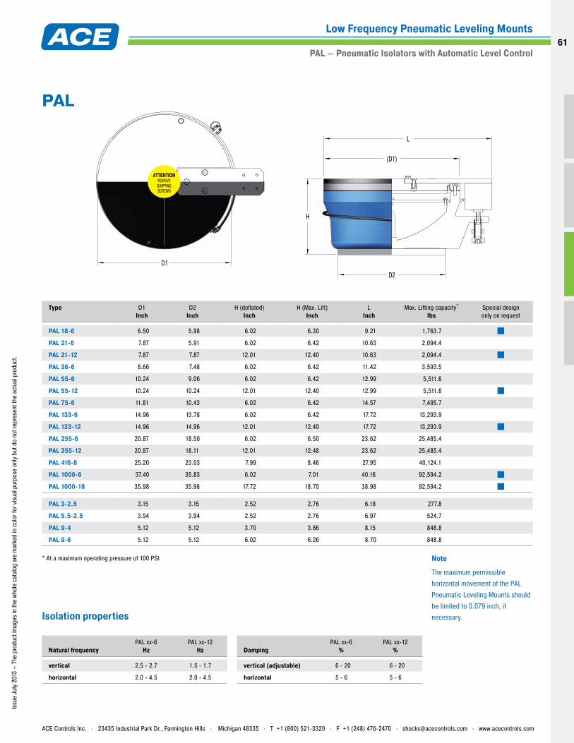
Issu
e Ju
ly 2
013
– Th
e pr
oduc
t im
ages
in th
e wh
ole
cata
log
are
mar
ked
in c
olor
for v
isua
l pur
pose
onl
y bu
t do
not r
epre
sent
the
actu
al p
rodu
ct.
Type
D1Inch
D2Inch
H (deflated)Inch
H (Max. Lift)Inch
LInch
Max. Lifting capacity*
IbsSpecial design only on request
PAL 18-6 6.50 5.98 6.02 6.30 9.21 1,763.7
PAL 21-6 7.87 5.91 6.02 6.42 10.63 2,094.4
PAL 21-12 7.87 7.87 12.01 12.40 10.63 2,094.4
PAL 36-6 8.66 7.48 6.02 6.42 11.42 3,593.5
PAL 55-6 10.24 9.06 6.02 6.42 12.99 5,511.6
PAL 55-12 10.24 10.24 12.01 12.40 12.99 5,511.6
PAL 75-6 11.81 10.43 6.02 6.42 14.57 7,495.7
PAL 133-6 14.96 13.78 6.02 6.42 17.72 13,293.9
PAL 133-12 14.96 14.96 12.01 12.40 17.72 13,293.9
PAL 255-6 20.87 18.50 6.02 6.50 23.62 25,485.4
PAL 255-12 20.87 18.11 12.01 12.48 23.62 25,485.4
PAL 416-8 25.20 23.03 7.99 8.46 27.95 40,124.1
PAL 1000-6 37.40 35.83 6.02 7.01 40.16 92,594.2
PAL 1000-18 35.98 35.98 17.72 18.70 38.98 92,594.2
PAL 3-2.5 3.15 3.15 2.52 2.76 6.18 277.8
PAL 5.5-2.5 3.94 3.94 2.52 2.76 6.97 524.7
PAL 9-4 5.12 5.12 3.70 3.86 8.15 848.8
PAL 9-6 5.12 5.12 6.02 6.26 8.70 848.8
* At a maximum operating pressure of 100 PSI
Natural frequencyPAL xx-6
HzPAL xx-12
Hz
vertical 2.5 - 2.7 1.5 - 1.7
horizontal 2.0 - 4.5 2.0 - 4.5
DampingPAL xx-6
%PAL xx-12
%
vertical (adjustable) 6 - 20 6 - 20
horizontal 5 - 6 5 - 6
ATTENTIONREMOVESHIPPINGSCREWS
D1
D2
H
(D1)
L
PAL
Isolation properties
Note
The maximum permissible horizontal movement of the PAL Pneumatic Leveling Mounts should be limited to 0.079 inch, if necessary.
ACE Controls Inc. . 23435 Industrial Park Dr., Farmington Hills . Michigan 48335 . T +1 (800) 521-3320 . F +1 (248) 476-2470 . [email protected] . www.acecontrols.com
Low Frequency Pneumatic Leveling Mounts
PAL – Pneumatic Isolators with Automatic Level Control61
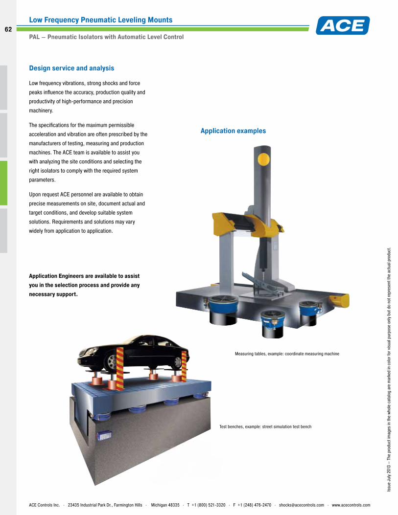
Issu
e Ju
ly 2
013
– Th
e pr
oduc
t im
ages
in th
e wh
ole
cata
log
are
mar
ked
in c
olor
for v
isua
l pur
pose
onl
y bu
t do
not r
epre
sent
the
actu
al p
rodu
ct.
Design service and analysis
Low frequency vibrations, strong shocks and force
peaks influence the accuracy, production quality and
productivity of high-performance and precision
machinery.
The specifications for the maximum permissible
acceleration and vibration are often prescribed by the
manufacturers of testing, measuring and production
machines. The ACE team is available to assist you
with analyzing the site conditions and selecting the
right isolators to comply with the required system
parameters.
Upon request ACE personnel are available to obtain
precise measurements on site, document actual and
target conditions, and develop suitable system
solutions. Requirements and solutions may vary
widely from application to application.
Application Engineers are available to assist you in the selection process and provide any necessary support.
Application examples
Measuring tables, example: coordinate measuring machine
Test benches, example: street simulation test bench
ACE Controls Inc. . 23435 Industrial Park Dr., Farmington Hills . Michigan 48335 . T +1 (800) 521-3320 . F +1 (248) 476-2470 . [email protected] . www.acecontrols.com
Low Frequency Pneumatic Leveling Mounts
PAL – Pneumatic Isolators with Automatic Level Control
62
62
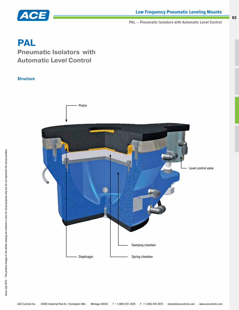
Issu
e Ju
ly 2
013
– Th
e pr
oduc
t im
ages
in th
e wh
ole
cata
log
are
mar
ked
in c
olor
for v
isua
l pur
pose
onl
y bu
t do
not r
epre
sent
the
actu
al p
rodu
ct.
Structure
PAL Pneumatic Isolators with Automatic Level Control
Damping chamber
Level control valve
Piston
Diaphragm Spring chamber
ACE Controls Inc. . 23435 Industrial Park Dr., Farmington Hills . Michigan 48335 . T +1 (800) 521-3320 . F +1 (248) 476-2470 . [email protected] . www.acecontrols.com
Low Frequency Pneumatic Leveling Mounts
PAL – Pneumatic Isolators with Automatic Level Control63
Issu
e Ju
ly 2
013
ACE Controls Inc. . 23435 Industrial Park Dr., Farmington Hills . Michigan 48335 . T +1 (800) 521-3320 . F +1 (248) 476-2470 . [email protected] . www.acecontrols.com
Automation Control Equipment
Notes/Sketch
64
64
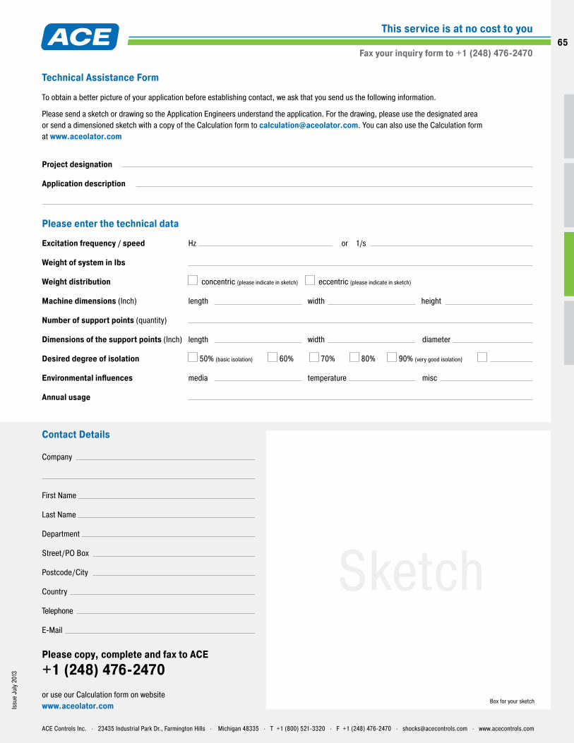
Issu
e Ju
ly 2
013
Contact Details
Company
First Name
Last Name
Department
Street/PO Box
Postcode/City
Country
Telephone
Please copy, complete and fax to ACE +1 (248) 476-2470or use our Calculation form on website www.aceolator.com
Box for your sketch
Sketch
ACE Controls Inc. . 23435 Industrial Park Dr., Farmington Hills . Michigan 48335 . T +1 (800) 521-3320 . F +1 (248) 476-2470 . [email protected] . www.acecontrols.com
Fax your inquiry form to +1 (248) 476-2470
This service is at no cost to you
Technical Assistance Form
To obtain a better picture of your application before establishing contact, we ask that you send us the following information.
Please send a sketch or drawing so the Application Engineers understand the application. For the drawing, please use the designated area or send a dimensioned sketch with a copy of the Calculation form to [email protected]. You can also use the Calculation form at www.aceolator.com
Project designation
Application description
Excitation frequency / speed Hz or 1/s
Weight of system in Ibs
Weight distribution concentric (please indicate in sketch) eccentric (please indicate in sketch)
Machine dimensions (Inch) length width height
Number of support points (quantity)
Dimensions of the support points (Inch) length width diameter
Desired degree of isolation 50% (basic isolation) 60% 70% 80% 90% (very good isolation)
Environmental influences media temperature misc
Annual usage
Please enter the technical data
65

Issu
e Ju
ly 2
013
ACE Controls Inc. . 23435 Industrial Park Dr., Farmington Hills . Michigan 48335 . T +1 (800) 521-3320 . F +1 (248) 476-2470 . [email protected] . www.acecontrols.com
Automation Control Equipment
Notes/Sketch
66
66

www.aceolator.com
ACEolatorIsolates Vibration
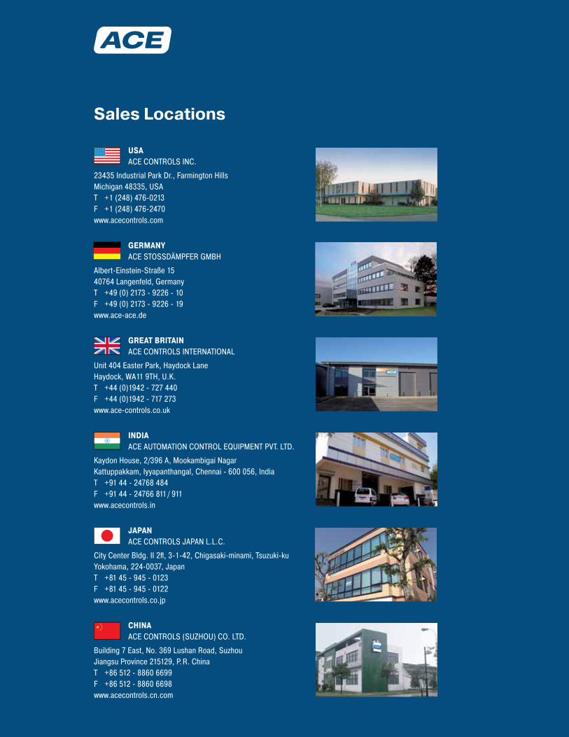
JAPAN ACE CONTROLS JAPAN L.L.C.
City Center Bldg. II 2fl, 3-1-42, Chigasaki-minami, Tsuzuki-ku Yokohama, 224-0037, Japan T +81 45 - 945 - 0123 F +81 45 - 945 - 0122 www.acecontrols.co.jp
GERMANY ACE STOSSDÄMPFER GMBH
Albert-Einstein-Straße 15 40764 Langenfeld, Germany T +49 (0) 2173 - 9226 - 10 F +49 (0) 2173 - 9226 - 19 www.ace-ace.de
GREAT BRITAIN ACE CONTROLS INTERNATIONAL
Unit 404 Easter Park, Haydock Lane Haydock, WA11 9TH, U.K. T +44 (0)1942 - 727 440 F +44 (0)1942 - 717 273 www.ace-controls.co.uk
INDIA ACE AUTOMATION CONTROL EQUIPMENT PVT. LTD.
Kaydon House, 2/396 A, Mookambigai Nagar Kattuppakkam, Iyyapanthangal, Chennai - 600 056, India T +91 44 - 24768 484 F +91 44 - 24766 811/ 911 www.acecontrols.in
USA ACE CONTROLS INC.
23435 Industrial Park Dr., Farmington Hills Michigan 48335, USA T +1 (248) 476-0213 F +1 (248) 476-2470 www.acecontrols.com
CHINA ACE CONTROLS (SUZHOU) CO. LTD.
Building 7 East, No. 369 Lushan Road, Suzhou Jiangsu Province 215129, P.R. China T +86 512 - 8860 6699 F +86 512 - 8860 6698 www.acecontrols.cn.com
Sales Locations