Embed Size (px)
Citation preview

IISSOONNIICC 22000099 UUPPAA--SSccooppee Portable Ultrasonic Phased Array Flaw Detector and Recorder
TTHHEE VVEERRSSAATTIILLIITTYY OOFF UULLTTRRAASSOONNIICCSS
Phased Array
64:64 phased array electronics – independently adjustable emitting and receiving aperture, parallel firing, A/D conversion, and on-the-fly real time digital phasing
Phased array pulser receiver with image guided ray tracing True-To-Geometry / regular B-Scan and Sector Scan (S-Scan) with all-codes-compliant A-Scan evaluation Unique Tandem-B-Scan for the detection of planar vertically oriented defects Built-in automatic coupling monitor and lamination checker for wedged probes Multi-group / dual side scanning and imaging with use of one probe Encoded / time-based line scanning with Top (C-Scan), Side, End Mapping and 3D Viewing Automatic generating of editable defects list Independent gain per focal law adjustment: pure angle gain compensation for S-Scan, etc DAC, TCG Processing of diffracted and mode converted signals for defects sizing and pattern recognition Operating matrix-array probes with real time three-dimensional imaging (3D-Scan)
Conventional UT and TOFD
1, or 8, or 16 channels Single / dual modes of pulsing/receiving Regular A-Scan Thickness B-Scan True-to-Geometry flaw detection B-
Scan – straight / angle beam probes CB-Scan TOFD Strip Chart and Stripped C-Scan Parallel or sequential pulsing/receiving
and A/D conversion DAC, DGS, TCG FFT signal analysis
100% raw data capturing Light rugged case Ethernet and 2 X USB Ports Powerful off-line data analysis toolkit Sealed keyboard and mouse Remote control – UT over IP Intuitive User Interface
Large 8.5” bright touch screen Built-in encoder port
Sonotron NDT 4, Pekeris str., Rabin Science Park, Rehovot, 76702, Israel Phone:++972-(0)8-9311000 Fax:++972-(0)8-9477712 www.sonotronndt.com

General
ISONIC 2009 UPA Scope uniquely combines phased array, single- and multi-channel conventional UT, and TOFD modalities providing 100% raw data recording and imaging. Along with portability, lightweight, and battery operation this makes it suitable for all kinds of every-day ultrasonic inspections
Phased array modality is performed by powerful 64:64 phased array electronics with independently adjustable emitting and receiving aperture, each may consist of 1 through 64 elements. Groups of phased array probe elements composing emitting and receiving aperture may be fully or partially matching or totally separated allowing flexible managing of incidence angles, focal distances, types of radiated and received waves including directly reflected and diffracted mode converted signals
Each channel is equipped with it’s own A/D converter. Parallel firing, A/D conversion, and ”on-the-fly” digital phasing are provided for every possible composition and size of the emitting and receiving aperture. Thus implementation of each focal law is completed within single pulsing/receiving cycle providing maximal possible inspection speed
Depending on configuration ISONIC 2009 UPA Scope carries 1, 8, or 16 additional independent channels for conventional UT and TOFD inspection and recording capable for both single and dual modes of pulsing/receiving
High ultrasonic performance is achieved through firing phased array, TOFD, and conventional probes with bipolar square wave initial pulse with wide-range-tunable duration and amplitude. Maximal amplitude of bipolar square wave initial pulse is 300 V pp for phased array and 400 V pp for conventional channels. High stability of the amplitude and shape of the initial pulse, boosting of all it’s leading and falling edges, and electronic damping are provided by the special circuit significantly improving signal to noise ratio and resolution. Thus analogue gain for each modality is controllable over 0…100 dB range
Large 800X600 pixels 8.5” bright screen provides fine resolution for all types of inspection data presentation
Phased Array Modality
Phased array pulser receiver is controlled through intuitive operating surface comprising user interface of conventional ultrasonic flaw detector and ray-tracing graphics. Type of wave generated in the material is controlled through key in of corresponding ultrasonic velocity. Trace of ultrasonic beam is truly imaged upon entering thickness, outside diameter, and other suitable geometry data characterizing object under test – this extremely simplifies creating of focal laws and calibration of the instrument as well
Signal evaluation fully compliant with conventional UT codes and procedures is applicable to A-Scans composed through implementing of various focal laws; DAC and TCG may be created either experimentally (up to 40 points) or theoretically through entering dB/mm (dB/inch) factor
Typical Phased Array Pulser Receiver screen of ISONIC 2009 UPA Scope
Cross-sectional insonification and imaging of the material may be provided electronically with use of linear array probes through:
Linear scanning with ultrasonic beam at predetermined incidence angle through reallocating of fixed size emitting/receiving aperture within entire array and composing of B-Scan image
Sectorial scanning with ultrasonic beam produced by fixed emitting/receiving aperture through steering of incidence angle in the predetermined range and composing of S-Scan image
Combining linear and sectorial scanning etc
Typical B-Scan indication of ISONIC 2009 UPA Scope representing inspection of composites for laminations: 1– scanning surface; 2 – bottom
surface; 3 – lamination; 4 – A-Scan corresponding to the position of cursor over image
S-Scan produced by ISONIC 2009 UPA Scope for several equal reflectors in the material with use of wedged linear array probe: 1 – angle gain compensation (AGC) is inactive; 2 – AGC is active; 3 – typical AGC graph
Regular (4) and true-to-geometry (5) S-Scan produced by ISONIC 2009 UPA Scope for compact reflector
located at 20 mm depth of 40 mm thick plate. On the regular S-Scan single compact reflector is indicated
twice for half (6) and full (7) skip detection while on the true-to-geometry S-Scan single reflector is shown in the
real position once for both ways of detection (8)
The effects of inequality of elements of linear array, varying sound path and loss in the delay line or wedge, dependency of energy of refracted wave and effective size of emitting/receiving aperture on incidence angle should be compensated to equalize the sensitivity over insonified cross-section. The unique feature of ISONIC 2009 UPA Scope is the ability of managing independently adjustable focal laws within the same frame-composing sequence of pulsing/receiving shots so every focal law may me executed with individually adjusted gain, time base, and other core settings providing:
Gain per Shot Correction for B-Scan Angle Gain Compensation for S-Scan True-to-Geometry imaging representing actual distribution of
ultrasonic beams and true-to-location indication of defects in the cross-sectional view of the material

Weld inspection is the typical application benefited through use of True-to-Geometry imaging: upon defining geometry and entering dimensions operator is provided with intuitive ray tracing dialogue indicating actual coverage of the weld for the desired probe position and incidence angle steering range followed by live cross-sectional view either S-Scan or B-Scan with true-to-location defects indication. To ensure detection of variously oriented defects several S-Scan and B-Scan insonifications may be performed simultaneously with use of the same probe providing multi-group cross-sectional viewing and recording along whole inspected length
In addition to simple geometry butt joints True-to-Geometry imaging technology is applicable to longitudinal, nozzle, fillet, TKY, corner, elbow welds, and the like

Testing of solid and hollow shafts, axles, rods, billets, etc are among other applications improved significantly thanks to the easy-to-interpret advantage of True-to-Geometry imaging vs regular S-Scan and B-Scan
True-to-Geometry S-Scan for single location and complete cross sectional image of the hollow shaft with defects obtained after full circumference scanning with linear array probe

True-to-Geometry S-Scan for longitudinal weld (1) and nozzle (2)
Tandem B-Scan is another unique feature of ISONIC 2009 UPA Scope being most effective technique for the detection of vertically situated cracks in welds, plates, tube and vessel walls, and the like. It may be implemented with use of wedged 64-elements linear array probe. On entering material thickness and defining a grid dividing object’s cross section into corresponding cells the instrument determines insonification strategy automatically by such a way that focal points of emitting and receiving aperture do match in the center of each cell in subsequent pulsing receiving cycles covering cross section completely. Individual gain per focal law adjustment is provided to equalize overall sensitivity for the variety of incidence angles, sound path lengths and losses in the wedge and material. For each focal law time base of the A-Scan is re-arranged automatically to provide appearance of possible echo from each cell at 50%-position. Recorded echo heights are represented on the Tandem B-Scan. Placing mouse cursor (marker) over desired cell reproduces corresponding A-Scan and ray trace indication
Defects pattern analysis may be carried with use of well-known Delta Technique allowing distinguishing between low risk compact volumetric defects and cracks. Shear wave insonification of the evaluated discontinuity is performed with receiving of both direct shear wave and diffracted longitudinal wave echoes using the same linear array probe. Both echoes have been evaluated automatically providing digital readout of so called KLS value, based on which defect pattern is determined
Implementation of Delta Technique is extremely simplified as only one linear array probe placed into position of receiving maximized echo from evaluated discontinuity is used instead of pair of conventional shear wave and
longitudinal wave probes. Corresponding screen of ISONIC 2009 UPA Scope indicates 2 individually adjustable A-Scans comprising direct shear wave echo (1) with AS amplitude, diffracted longitudinal wave echo (2) with AL
amplitude, and digital readout of KLS value (3) rating AS/AL
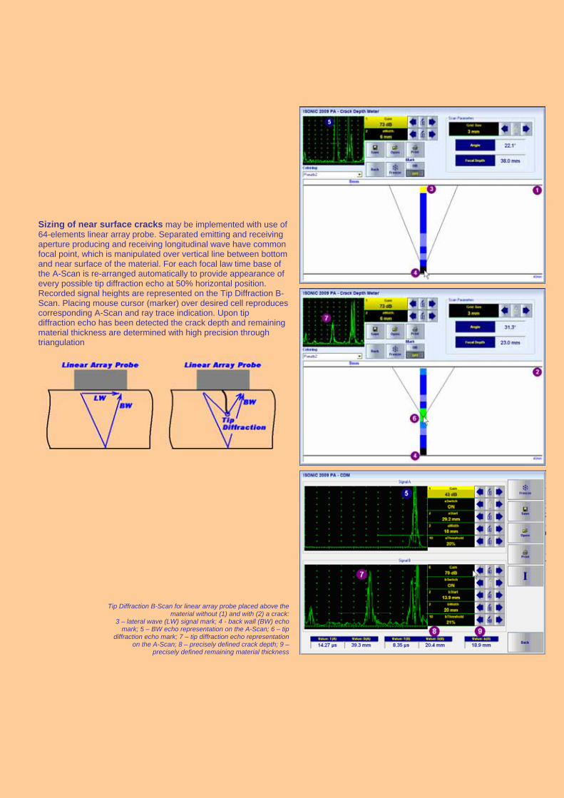
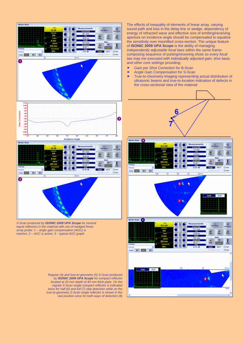
Sizing of near surface cracks may be implemented with use of 64-elements linear array probe. Separated emitting and receiving aperture producing and receiving longitudinal wave have common focal point, which is manipulated over vertical line between bottom and near surface of the material. For each focal law time base of the A-Scan is re-arranged automatically to provide appearance of every possible tip diffraction echo at 50% horizontal position. Recorded signal heights are represented on the Tip Diffraction B-Scan. Placing mouse cursor (marker) over desired cell reproduces corresponding A-Scan and ray trace indication. Upon tip diffraction echo has been detected the crack depth and remaining material thickness are determined with high precision through triangulation
Tip Diffraction B-Scan for linear array probe placed above the material without (1) and with (2) a crack:
3 – lateral wave (LW) signal mark; 4 - back wall (BW) echo mark; 5 – BW echo representation on the A-Scan; 6 – tip
diffraction echo mark; 7 – tip diffraction echo representation on the A-Scan; 8 – precisely defined crack depth; 9 –
precisely defined remaining material thickness
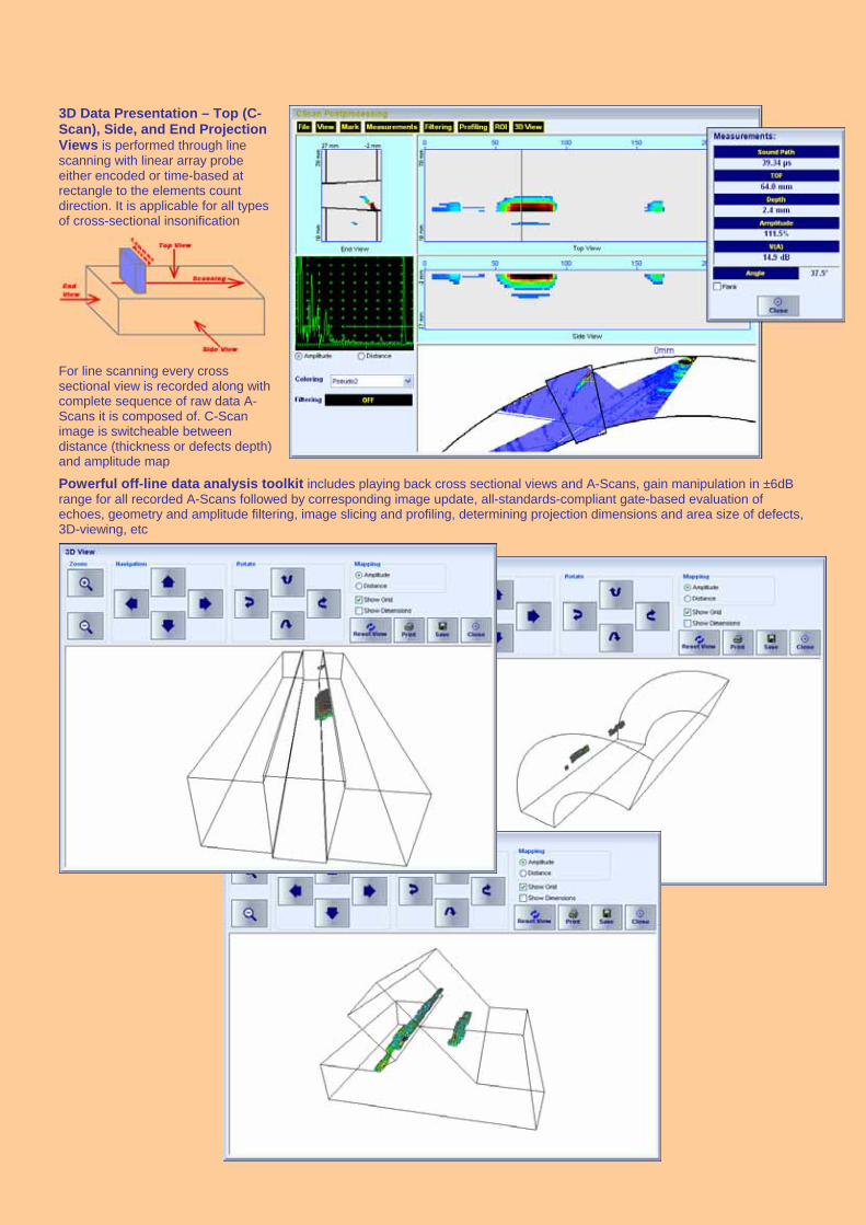
3D Data Presentation – Top (C-Scan), Side, and End Projection Views is performed through line scanning with linear array probe either encoded or time-based at rectangle to the elements count direction. It is applicable for all types of cross-sectional insonification
For line scanning every cross sectional view is recorded along with complete sequence of raw data A-Scans it is composed of. C-Scan image is switcheable between distance (thickness or defects depth) and amplitude map
Powerful off-line data analysis toolkit includes playing back cross sectional views and A-Scans, gain manipulation in ±6dB range for all recorded A-Scans followed by corresponding image update, all-standards-compliant gate-based evaluation of echoes, geometry and amplitude filtering, image slicing and profiling, determining projection dimensions and area size of defects, 3D-viewing, etc

Use of Matrix Array Probes and 3D-Scan Imaging
In addition to cross sectional insonification (2D) and imaging with linear arrays ISONIC 2009 UPA Scope allows performing of volumetric insonification (3D); matrix array probes are used for that purpose. Use of matrix arrays is possible thanks to parallel firing, A/D conversion, and ”on-the-fly” digital phasing provided by 64:64 phased array electronics. At the calibration stage phased array pulser receiver is controlled through operating surface of conventional ultrasonic flaw detector supported by 3D ray-tracing graphics. 3D region of interest (ROI) is defined then. The innovative live true-to-geometry 3D-Scan L image is composed then for each position of matrix array probe manipulated over material surface
Phased Array Pulser Receiver for matrix array probe is supported by 3D ray-tracing graphics
3D Region of Interest (ROI)

For shear wave weld inspection matrix array should be coupled to the wedge, which’s contact face width allows swiveling of ultrasonic beam in the desired range. On entering dimensions of the weld, probe position, and limits for swiveling angle scanning along fusion line may be implemented without typical mechanical skewing of the probe with no risk of missing transversally situated defects. The innovative live true-to-geometry 3D-Scan S image is provided for every lateral position of the probe; 100% raw data capturing is provided so every A-Scan may be played back at the postprocessing stage along with corresponding Top, Side, and End projection views
Phased Array Pulser Receiver for wedged matrix array probe – beam incidence and swiveling angles are flexibly manipulated
3D definition of weld coverage through keying in weld dimensions, probe position, and limits for beam swiveling angle
Real time shear wave 3D-Scan S screen for weld inspection: 1 – footprint of the wedge; 2 – indication of limits for swiveling angle; 3 – heat affected zone; 4 – weld metal; 5 – parent material adjacent to heat affected zone; 6 – defect (lack of fusion); 7 – A-Scan representing defect echo for the focal law desired by operator

Conventional UT and TOFD modalities
For single conventional channel operation ISONIC 2009 UPA Scope provides fully featured A-Scan inspection as well as line scanning recording and imaging of the following types: thickness B-Scan; flaw detection B-Scan for angle beam and straight beam probes; CB-Scan for guided, surface, and shear wave probes inspections; TOFD. This fully covers scope of functions implemented by very well known ISONIC 2005 / ISONIC STAR / ISONIC 2020 portable ultrasonic flaw detector and recorder of Sonotron NDT – www.sonotronndt.com/i2005.htm
ISONIC 2009 UPA Scope instruments equipped with 8 or 16 channels additionally provide multi-channel strip chart recording with forming all known types of strips such as B-Scan, PE, TOFD, Coupling. For certain applications such as, for example, brush probe scanning strip chart is convertible into C-Scan. This fully covers scope of functions implemented by very well known ISONIC 2008 portable multi-channel ultrasonic flaw detector and recorder of Sonotron NDT – www.sonotronndt.com/i2008.htm
Comprehensive off-line analysis and data reporting toolkit for all kinds of data captured using conventional UT and TOFD modalities is built-in
Remote Control – UT over IP
Remote control of ISONIC 2009 UPA is implemented through Ethernet port. The instrument is fully compatible with new UT over IP technology from Sonotron NDT allowing full control of the instrument, imaging, recording, and storage inspection data in the remote control computer Compliancy with international and national codes
ISONIC 2009 UPA Scope is fully compliant with the following codes
ASME Code Case 2541 – Use of Manual Phased Array Ultrasonic Examination Section V ASME Code Case 2557 – Use of Manual Phased Array S-Scan Ultrasonic Examination Section V per Article 4
Section V ASME Code Case 2558 – Use of Manual Phased Array E-Scan Ultrasonic Examination Section V per Article 4
Section V ASTM 1961– 06 – Standard Practice for Mechanized Ultrasonic Testing of Girth Welds Using Zonal Discrimination
with Focused Search Units ASME Section I – Rules for Construction of Power Boilers ASME Section VIII, Division 1 – Rules for Construction of Pressure Vessels ASME Section VIII, Division 2 – Rules for Construction of Pressure Vessels. Alternative Rules ASME Section VIII Article KE-3 – Examination of Welds and Acceptance Criteria ASME Code Case 2235 Rev 9 – Use of Ultrasonic Examination in Lieu of Radiography Non-Destructive Examination of Welded Joints – Ultrasonic Examination of Welded Joints. – British and European
Standard BS EN 1714:1998 Non-Destructive Examination of Welds – Ultrasonic Examination – Characterization of Indications in Welds. –
British and European Standard BS EN 1713:1998 Calibration and Setting-Up of the Ultrasonic Time of Flight Diffraction (TOFD) Technique for the Detection, Location
and Sizing of Flaws. – British Standard BS 7706:1993 WI 00121377, Welding – Use Of Time-Of-Flight Diffraction Technique (TOFD) For Testing Of Welds. – European
Committee for Standardization – Document # CEN/TC 121/SC 5/WG 2 N 146, issued Feb, 12, 2003 ASTM E 2373 – 04 – Standard Practice for Use of the Ultrasonic Time of Flight Diffraction (TOFD) Technique Non-Destructive Testing – Ultrasonic Examination – Part 5: Characterization and Sizing of Discontinuities. – British
and European Standard BS EN 583-5:2001 Non-Destructive Testing – Ultrasonic Examination – Part 2: Sensitivity and Range Setting. – British and European
Standard BS EN 583-2:2001 Manufacture and Testing of Pressure Vessels. Non-Destructive Testing of Welded Joints. Minimum Requirement
for Non-Destructive Testing Methods – Appendix 1 to AD-Merkblatt HP5/3 (Germany).– Edition July 1989

ISONIC 2009 PA UPA-Scope –Technical Data Phased Array
Pulse Type: Bipolar Square Wave with electronically controlled damping Initial Transition: 7.5 ns (10-90% for rising edges / 90-10% for falling edges) Pulse Amplitude: Smoothly tunable (12 levels) 50V … 300 V pp into 50 Half Wave Pulse Duration: 50…600 ns controllable in 10 ns step Probe Types: Linear / Ring / Matrix Array Emitting aperture: 1…64 Phasing (emitting aperture): 0…100 s with 5 ns resolution Receiving Aperture: 1…64 Gain: 0...100 dB controllable in 0.5 dB resolution Advanced Low Noise Design: 85 V peak to peak input referred to 80 dB gain / 25 MHz bandwidth Frequency Band: 0.2 … 25 MHz Wide Band A/D Conversion: 100 MHz 16 bit Superimposing of receiving aperture signals: On-the-fly, no multiplexing involved Phasing (receiving aperture): On-the-fly 0…100 s with 5 ns resolution A-Scan Display Modes: RF, Rectified (Full Wave / Negative or Positive Half Wave) DAC / TCG per focal law – for rectified and RF display:
Theoretical – dB/mm (dB/") Experimental – through recording echoes from several reflectors 46 dB Dynamic Range, Slope 20 dB/s, Capacity 40 points
Gates per focal law: 2 Independent Gates / unlimitedly expandable Gate Start and Width: Controllable over whole variety of A-Scan Display Delay and A-Scan Range
in 0.1 mm /// 0.001" resolution Gate Threshold: 5…95 % of A-Scan height controllable in 1 % resolution Number of focal laws: 8192 Scanning and Imaging: B-Scan (E-Scan) – regular and True-To-Geometry
Sector Scan (S-Scan) – regular and True-To-Geometry One-probe multi-group image composed from several B- and S-Scans Tandem-B-Scan – True-To-Geometry (for the detection of planar vertically oriented defects) Top (C-Scan), Side, End View imaging formed through encoded / time-based line scanning, 3D-Viewer Real time 3D-Scan composed with use of Matrix Array Probes
Method of data storage:
100% raw data capturing
Conventional UT and TOFD Number of Channels 1 or 8 or 16 Pulsing/Receiving Methods (for 8 or 16 conventional channels):
Parallel - all channels do fire, receive, digitize, and record signals simultaneously Sequential – cycles of firing, receiving, digitizing, and recording signals by each channel are separated in time in a sequence loop
Pulse Type: Bipolar Square Wave with electronically controlled damping Initial Transition: 7.5 ns (10-90% for rising edges / 90-10% for falling edges) Pulse Amplitude: Smoothly tunable (12 levels) 50V … 400 V pp into 50 Half Wave Pulse Duration: 50…600 ns independently controllable in 10 ns step Modes: Single / Dual Gain: 0...100 dB controllable in 0.5 dB resolution Advanced Low Noise Design: 85 V peak to peak input referred to 80 dB gain / 25 MHz bandwidth Frequency Band: 0.2 … 25 MHz Wide Band A/D Conversion: 100 MHz 16 bit Digital Filter: 32-Taps FIR band pass with controllable lower and upper frequency limits A-Scan Display Modes: RF, Rectified (Full Wave / Negative or Positive Half Wave), Signal's Spectrum (FFT Graph) DAC / TCG – for rectified and RF display: Theoretical – dB/mm (dB/")
Experimental – through recording echoes from several reflectors 46 dB Dynamic Range, Slope 20 dB/s, Capacity 40 points
DGS: Standard Library for 18 probes / unlimitedly expandable Gates: 2 Independent Gates / unlimitedly expandable Gate Start and Width: Controllable over whole variety of A-Scan Display Delay and A-Scan Range
in 0.1 mm /// 0.001" resolution Gate Threshold: 5…95 % of A-Scan height controllable in 1 % resolution Measuring Functions – Digital Display Readout:
27 automatic functions / expandable; Dual Ultrasound Velocity Measurement Mode for Multi-Layer Structures; Curved Surface / Thickness / Skip correction for angle beam probes; Ultrasound velocity and Probe Delay Auto-Calibration for all types of probes
Freeze (A-Scans and Spectrum Graphs): Freeze All / Freeze Peak – signal evaluation, manipulating Gates and Gain is possible for frozen signals as for live
Scanning and Imaging: Single Channel: Thickness Profile B-Scan, Cross-sectional B-Scan, Plane View CB-Scan, TOFD Multi-Channel: Strip Charts of 4 types (Amplitude/TOFD P/E, Map, TOFD, Coupling)
Standard Length of one Line Scanning record:
50…20000 mm (2"…800"), automatic scrolling
Method of data storage:
100% raw data capturing
General PRF: 10...5000 Hz controllable in 1 Hz resolution On-Board Computer CPU: AMD LX 800 - 500MHz RAM: 1 Gigabyte Internal Flash Memory - Quasi HDD: 4 Gigabytes Screen: Sun readable 8.5” touch screen 800 600 Controls: Sealed keyboard and mouse Interface: 2 USB, Ethernet Operating System: WindowsXP Embedded Encoder interface: Incremental TTL encoder Housing:
IP 53 rugged aluminum case with carrying handle Dimensions: 314224124 mm (12.36”8.82”4.88”) – without battery
314224152 mm (12.36”8.82”5.98”) – with battery
Weight:
4.550 kg (10.01 lbs) – without battery 5.480 kg (12.06 lbs) – with battery
Updated March 6, 2011