Embed Size (px)
Citation preview

ISRM Modelling Guidelines
Document informationProject Title Information Service Modelling deliverablesProject Number 08.03.10Project Manager NORACONDeliverable Name ISRM Modelling GuidelinesDeliverable ID D45Edition 00.08.00Template Version 03.00.00Task contributorsDFS, EUROCONTROL, NORACON, NATMIG, FINMECCANICA
AbstractThe modelling guideline is part of the ISRM foundation. It gives step by step instructions for service modellers and service architects to design service models on a logical level.

Project Number 08.03.10 Edition 00.08.00D45 - ISRM Modelling Guidelines
Authoring & ApprovalPrepared By - Authors of the document.
Name & Company Position & Title DateOliver Schrempf, DFS Project Member 17/05/2016Tord Pola, NORACON Project Manager 20/04/2016
Reviewed By - Reviewers internal to the project.
Name & Company Position & Title DateP08.03.10 project membersWalter Van Hamme / EUROCONTROL 8.3.10 Contributor 30/03/2016Serena Rubbioli / IDS 8.3.10 Contributor 23/05/2016Tom Erik White / NORACON 8.3.10 Contributor 23/05/2016
Reviewed By - Other SESAR projects, Airspace Users, staff association, military, Industrial Support, other organisations.
Name & Company Position & Title Date
Approved for submission to the SJU By - Representatives of the company involved in the project.
Name & Company Position & Title DateTord Pola / NORACON Project Manager 31/05/2016
Rejected By - Representatives of the company involved in the project.
Name & Company Position & Title Date
Rational for rejectionNone.
Document HistoryEdition Date Status Author Justification00.00.01 18.04.2011 Draft Florian Kraus New Document, based on
“ISRM Guide for modellers” V00.01.00
00.00.02 04.05.2011 Draft Florian Kraus Draft of modelling process created.
00.00.03 12.05.2011 Draft Florian Kraus Incorporated feedback from training preparation and input from Noracon
00.00.04 25.05.2011 Draft Florian Kraus Finalised all chapters except chapter 4
00.00.05 09.06.2011 Draft Daniel Berg Added information on collaborative process and QoS examples.
00.01.00 10.06.2011 Final Oliver Krueger Reviewed Document
00.01.01 07.07.2011 Final Florian Kraus Amended chapter 8.2 Messages and Data Types
2 of 53©SESAR JOINT UNDERTAKING, 2015. Created by DFS, EUROCONTROL, NORACON, NATMIG, FINMECCANICA for the SESAR Joint Undertaking within the frame of the SESAR Programme co-financed by the EU and EUROCONTROL. Reprint with approval of publisher and the source properly acknowledged

Project Number 08.03.10 Edition 00.08.00D45 - ISRM Modelling Guidelines
00.01.02 31.05.2012 Draft Oliver Krueger Interim Version including NWF process steps
00.01.03 04.06.2012 Final Oliver Krueger Updated after comments
00.01.04 18.06.2012 Final Tord Pola Change control reworked
00.01.05 19/06/2012 Final Oliver Krueger Finalisation after additional review
00.01.06 28/06/2012 Final Svein G. Johnsen Inserted index.
00.01.07 24/04/2013 Draft Ashley Williams New Structure
00.01.08 08/05/2013 Draft Ashley WilliamsMichel DenysTord Pola
Modelling Guidelines Workshop in Copenhagen from 7th until 8th May 2013
00.01.09 22/05/2013 Draft Michel Denys Ashley Williams
Added section Input Assessment phase and Identify Service
00.01.10 27/05/2013 Draft Ashley Williams Updated Identify Service
00.01.11 27/05/2013 Draft Michel Denys Added the section on Service allocation
00.01.12 28/05/2013 Draft Ashley Williams Added the Appendix sections on, updated Identify Service, section Design Service Added
00.01.13 29/05/2013 Draft 8.3.10 WS Oslo 28th/29th of May 2013
Comments
00.01.14 29/05/2013 Draft Ashley Williams Chapter and Appendix changed and added
00.01.15 31/05/2013 Draft Ashley Williams Minor and major changes
00.01.16 03/06/2013 Draft Ashley Williams Minor and major changes
00.01.17 04/06/2013 Draft Ashley Williams Minor and major changes
00.01.18 06/06/2013 Draft Ashley Williams Minor and major changes / Comments of Leslie Folds
00.01.19 06/06/2013 Draft Ashley Williams Webex 06/06/2013, Bjørn Solberg, Tord Pola, Ashley Williams
00.01.20 06/06/2013 Draft Ashley Williams Minor and major changes
00.02.00 07/06/2013 Final Ashley Williams Minor and major changes / Comments of Leslie Folds
00.02.01 12.09.2013 Final Svein G. Johnsen Minor changes.
00.02.02 31.10.2013 Draft Oliver Schrempf EATMA compatibility
00.02.03 02.12.2013 Draft Lars-Olof Kihlström Profile use, taxonomy and data content
00.02.04 20.12.2013 Draft Lars-Olof Kihlström General how-to update
00.02.05 17.01.2014 Draft Lars-Olof Kihlström Comments handled
00.02.06 02.02.2014 Draft Lars-Olof Kihlström Examples included
00.02.07 17.02.2014 Draft Lars-Olof Kihlström Comments and changes to profile included.
00.02.08 26.02.2014 Draft Oliver Schrempf Update Design Chapter
00.03.00 06.03.2014 Final Oliver Schrempf Incorporate Comments
00.03.01 18.03.2014 Draft Oliver Schrempf Implementation of Change Requests CR-3 and CR-10 (Payload mapping)
3 of 53©SESAR JOINT UNDERTAKING, 2015. Created by DFS, EUROCONTROL, NORACON, NATMIG, FINMECCANICA for the SESAR Joint Undertaking within the frame of the SESAR Programme co-financed by the EU and EUROCONTROL. Reprint with approval of publisher and the source properly acknowledged

Project Number 08.03.10 Edition 00.08.00D45 - ISRM Modelling Guidelines
00.03.02 20.03.2014 Draft Oliver Schrempf Implementation of Change Request CR-15 (map to role)
00.03.03 25.02.2014 Draft Trond NatlandOliver Schrempf
CR-12 (SDD generation)CR-2 (alternative mapping)
00.03.04 27.03.2014 Draft Oliver Schrempf Incorporated comments from Svein Johnsen (NATMIG)
00.03.05 02.04.2014 Draft Oliver Schrempf Incorporated Review Comments
00.03.10 09.04.2014 Final Oliver Schrempf Preparation for final delivery
00.04.00 13.05.2014 Final Oliver Schrempf CR-14 Updated template CR-8 Service namingCR-18 drop activity reportCR-32 Fix typoCR-31/38 Rule SM580CR-41 direction of serviceSupportsActivityCR-44 lowerCamelCaseCR-6 Naming of ServiceLevelsCR-7 reference MEP Source
00.04.01 28.08.2014 Final Gianluca MarrazzoStefan KellerOliver Schrempf
CR-59 Role NamesCR-62 Tracing to AIRM IMCR-63 Cleanup from Exchange ModelsCR-64 Allow Multiple Tracings to AIRM
00.05.00 16.12.2014 Final Oliver SchrempfOliver KrügerNiklas HäggströmBjørn SolbergSvein G. Johnsen
CR-5 reorganize IER placementCR-20 remove service functionsCR-60 Fix wording of IER descriptionCR-43 Make Capability Mapping mandatoryCR-45 Correct rule SM260CR-61Extend rule SM320CR-19 Example for optional viewsCR-68 Drop Node to Interface mappingCR-69 Handling new abbreviationsCR-70 Update Service Allocation/NSV-12 guidelinesCR-71 Reorganize Tasks within Service Identification and Service DesignCR-72 Consolidate modelling of Operational and Business Context into one chapterCR-73 Move the Operational modelling to Support to OPS chapterCR-74 Update use/modelling of Nodes in NSOV-4CR-75 Restrictions on service naming.CR-87 Fix modelling on
4 of 53©SESAR JOINT UNDERTAKING, 2015. Created by DFS, EUROCONTROL, NORACON, NATMIG, FINMECCANICA for the SESAR Joint Undertaking within the frame of the SESAR Programme co-financed by the EU and EUROCONTROL. Reprint with approval of publisher and the source properly acknowledged

Project Number 08.03.10 Edition 00.08.00D45 - ISRM Modelling Guidelines
items not owned by ISRM00.06.00 27.05.2015 Final Oliver Schrempf
Niklas HäggströmSvein G. JohnsenTom Erik White
CR-09 Service and Data Modeller cooperation for payload modellingCR-95 Model dependencies between interfacesCR-91 Fix for Guidelines for NOV-2 NodeRealizationOfServicesCR-97 Add design goalsCR-92 Fix for SM600
00.07.00 5.12.2015 Final Oliver SchrempfGianluca MarrazzoBjørn SolbergAre KjæraasTord Pola
CR-98 Remove Taxonomy from ISRMCR-119 Replace attribute-based NFRs by traces to text-based requirements (SPRs).CR-113 Modelling of Enumeration, plus major improvement and simplification on all payload modelling section.CR-117 Consistent use of diagram namesCR-123 Describe MEP usageCR-125 Show Property Note in diagramCR-130 Cleanup subpackage structure
00.08.00 25.05.2016 Final Oliver SchrempfTord Pola
Preparation of SESAR agnostic Foundation
Intellectual Property Rights (foreground)This deliverable consists of SJU foreground.
5 of 53©SESAR JOINT UNDERTAKING, 2015. Created by DFS, EUROCONTROL, NORACON, NATMIG, FINMECCANICA for the SESAR Joint Undertaking within the frame of the SESAR Programme co-financed by the EU and EUROCONTROL. Reprint with approval of publisher and the source properly acknowledged

Project Number 08.03.10 Edition 00.08.00D45 - ISRM Modelling Guidelines
Table of ContentsEXECUTIVE SUMMARY.....................................................................................................................................9
1 INTRODUCTION.........................................................................................................................................10
1.1 PURPOSE OF THE DOCUMENT.................................................................................................................101.2 INTENDED READERSHIP..........................................................................................................................101.3 INPUTS FROM OTHER PROJECTS..............................................................................................................101.4 GLOSSARY OF TERMS.............................................................................................................................101.5 ACRONYMS AND TERMINOLOGY............................................................................................................11
2 DESIGN SERVICE.......................................................................................................................................12
2.1 DESIGN GOALS.......................................................................................................................................122.2 OUTPUT..................................................................................................................................................13
2.2.1 Package structure..............................................................................................................................132.3 STEPS TO BE PERFORMED.......................................................................................................................14
2.3.1 Step 1: Identify and uniquely name service.......................................................................................152.3.2 Step 2: Map Service to Requirements (IER and NFR)......................................................................172.3.3 Step 3: Specify Ports and MEPs........................................................................................................182.3.4 Step 4: Specify Interfaces..................................................................................................................212.3.5 Step 5: Specify Interface Operations.................................................................................................212.3.6 Step 6: Specify Operation Parameters..............................................................................................222.3.7 Step 7: Specify Service Payload design............................................................................................232.3.8 Step 8: Trace Service Payload to AIRM...........................................................................................262.3.9 Step 9: Specify event trace description.............................................................................................26
3 REFERENCES..............................................................................................................................................29
APPENDIX A ISRM SWIM MESSAGE EXCHANGE PATTERNS........................................................30
A.1 Synchronous request/reply................................................................................................................30A.2 Asynchronous request/reply..............................................................................................................31A.3 Publish/Subscribe Push.....................................................................................................................32A.4 Publish/Subscribe Pull......................................................................................................................33A.5 One Way............................................................................................................................................34
APPENDIX B ISRM NAMING CONVENTIONS.......................................................................................35
B.1 SERVICE NAMING CONVENTIONS...........................................................................................................35B.2 SERVICE PORT AND INTERFACE NAMING CONVENTIONS.......................................................................37
B.2.1 Interface naming in case of request/reply pattern (synchronous and asynchronous)......................38B.2.2 Interface naming in case of publish/subscribe pattern.....................................................................38B.2.3 Interface naming in case of one-way pattern....................................................................................38
B.3 SERVICE INTERFACE OPERATIONS NAMING CONVENTIONS...................................................................38B.4 MESSAGES/SERVICE INTERFACE PARAMETERS NAMING CONVENTIONS...............................................40
APPENDIX C EXAMPLE OF SERVICE WITH TWO PORTS...............................................................41
APPENDIX D TECHNICAL MODELLING SUPPORT............................................................................46
D.1 SWIM LOGICAL SERVICE TOOLBOX......................................................................................................46D.1.1 TOOLBOX INSTALLATION.......................................................................................................................46D.1.2 TOOLBOX USAGE....................................................................................................................................49D.2 VERIFICATION SCRIPT............................................................................................................................51
6 of 53©SESAR JOINT UNDERTAKING, 2015. Created by DFS, EUROCONTROL, NORACON, NATMIG, FINMECCANICA for the SESAR Joint Undertaking within the frame of the SESAR Programme co-financed by the EU and EUROCONTROL. Reprint with approval of publisher and the source properly acknowledged

Project Number 08.03.10 Edition 00.08.00D45 - ISRM Modelling Guidelines
List of tablesTable 1: Glossary and terms................................................................................................................. 10
Table 2: Acronyms................................................................................................................................ 11
List of figuresFigure 1: Example project browser structure........................................................................................13
Figure 2: The steps of the service design process...............................................................................15
Figure 3: Example of Service Element in Package Structure...............................................................16
Figure 4: Example of Interface Definition Diagram...............................................................................17
Figure 5: Example Requirements Traceability diagram........................................................................18
Figure 6: Example of Service port in package structure.......................................................................20
Figure 7: Example of modelled MEP choice.........................................................................................20
Figure 8: Example of a Service with multiple interfaces.......................................................................20
Figure 9: Example of a service interface..............................................................................................21
Figure 10: Example of an interface definition diagram with operations.................................................22
Figure 11: Illustrative diagram showing service operation parameters and their payload elements.....23
Figure 12: Example of a payload structure...........................................................................................24
Figure 13: Example of a structured “Complete Model” payload............................................................25
Figure 14: Example of a payload based on a standard exchange model.............................................26
Figure 15: Example of Sequence Diagram...........................................................................................27
Figure 16: Example of Sequence Diagram with message....................................................................27
Figure 17: Example of Sequence Diagram with fragments...................................................................28
Figure 18: Synchronous request/reply MEP Event Trace diagram.......................................................30
Figure 19: Synchronous request/reply MEP Interface Definition diagram...........................................30
Figure 20: Asynchronous request/reply MEP Event Trace diagram.....................................................31
Figure 21: Asynchronous request/reply MEP Interface Definition diagram...........................................31
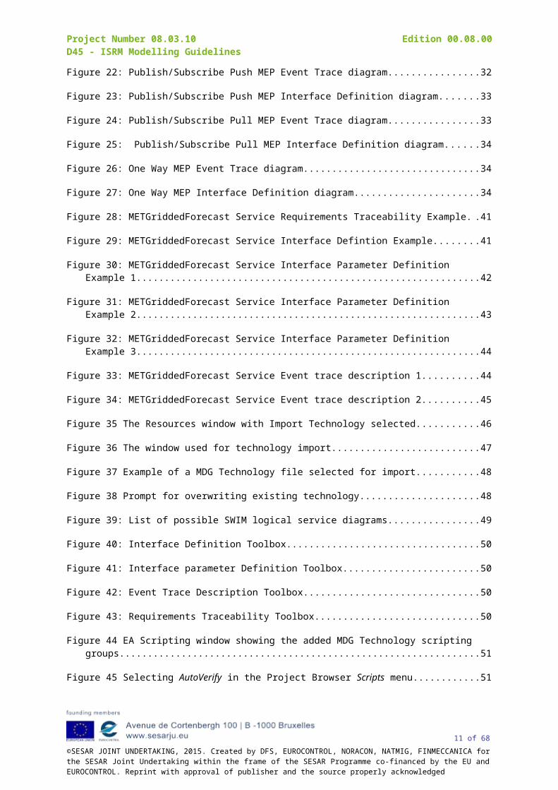
Figure 22: Publish/Subscribe Push MEP Event Trace diagram............................................................32
Figure 23: Publish/Subscribe Push MEP Interface Definition diagram.................................................33
Figure 24: Publish/Subscribe Pull MEP Event Trace diagram..............................................................33
7 of 53©SESAR JOINT UNDERTAKING, 2015. Created by DFS, EUROCONTROL, NORACON, NATMIG, FINMECCANICA for the SESAR Joint Undertaking within the frame of the SESAR Programme co-financed by the EU and EUROCONTROL. Reprint with approval of publisher and the source properly acknowledged

Project Number 08.03.10 Edition 00.08.00D45 - ISRM Modelling Guidelines
Figure 25: Publish/Subscribe Pull MEP Interface Definition diagram..................................................34
Figure 26: One Way MEP Event Trace diagram...................................................................................34
Figure 27: One Way MEP Interface Definition diagram........................................................................34
Figure 28: METGriddedForecast Service Requirements Traceability Example....................................41
Figure 29: METGriddedForecast Service Interface Defintion Example................................................41
Figure 30: METGriddedForecast Service Interface Parameter Definition Example 1...........................42
Figure 31: METGriddedForecast Service Interface Parameter Definition Example 2...........................43
Figure 32: METGriddedForecast Service Interface Parameter Definition Example 3...........................44
Figure 33: METGriddedForecast Service Event trace description 1.....................................................44
Figure 34: METGriddedForecast Service Event trace description 2.....................................................45
Figure 35 The Resources window with Import Technology selected....................................................46
Figure 36 The window used for technology import...............................................................................47
Figure 37 Example of a MDG Technology file selected for import........................................................48
Figure 38 Prompt for overwriting existing technology...........................................................................48
Figure 39: List of possible SWIM logical service diagrams...................................................................49
Figure 40: Interface Definition Toolbox.................................................................................................50
Figure 41: Interface parameter Definition Toolbox................................................................................50
Figure 42: Event Trace Description Toolbox.........................................................................................50
Figure 43: Requirements Traceability Toolbox.....................................................................................50
Figure 44 EA Scripting window showing the added MDG Technology scripting groups.......................51
Figure 45 Selecting AutoVerify in the Project Browser Scripts menu...................................................51
Figure 46: The process of AutoVerify execution and verification report generation..............................52
8 of 53©SESAR JOINT UNDERTAKING, 2015. Created by DFS, EUROCONTROL, NORACON, NATMIG, FINMECCANICA for the SESAR Joint Undertaking within the frame of the SESAR Programme co-financed by the EU and EUROCONTROL. Reprint with approval of publisher and the source properly acknowledged

Project Number 08.03.10 Edition 00.08.00D45 - ISRM Modelling Guidelines
Executive summaryThe modelling guideline is part of the ISRM foundation and gives step by step instructions for the service modellers and service architects to design ATM SWIM services on a logical level. The guideline is not a SOA tutorial (the modellers are supposed to have full maturity in identifying and designing SOA services) and does not repeat the information found in the other documents.This document shall be seen as a guideline for designing logical service models following the rules given in the ISRM Foundation Rulebook [4] and serving as a means of compliance as defined by the SWIM Compliance Framework [9].ISRM SWIM service models are logical in the sense that they provide a formal systematic translation of operational and non-functional requirements into a standardised language using the Unified Modelling Language (UML) without making any technological assumptions or demands. This is achieved by describing service interfaces and service payloads. Interface descriptions are the building blocks for supporting technical interoperability between Service Providers and Consumers. Payloads of ISRM Services are traced to the ATM Information Reference Model (AIRM) [4] for achieving semantic interoperability.
9 of 53©SESAR JOINT UNDERTAKING, 2015. Created by DFS, EUROCONTROL, NORACON, NATMIG, FINMECCANICA for the SESAR Joint Undertaking within the frame of the SESAR Programme co-financed by the EU and EUROCONTROL. Reprint with approval of publisher and the source properly acknowledged

Project Number 08.03.10 Edition 00.08.00D45 - ISRM Modelling Guidelines
1 Introduction
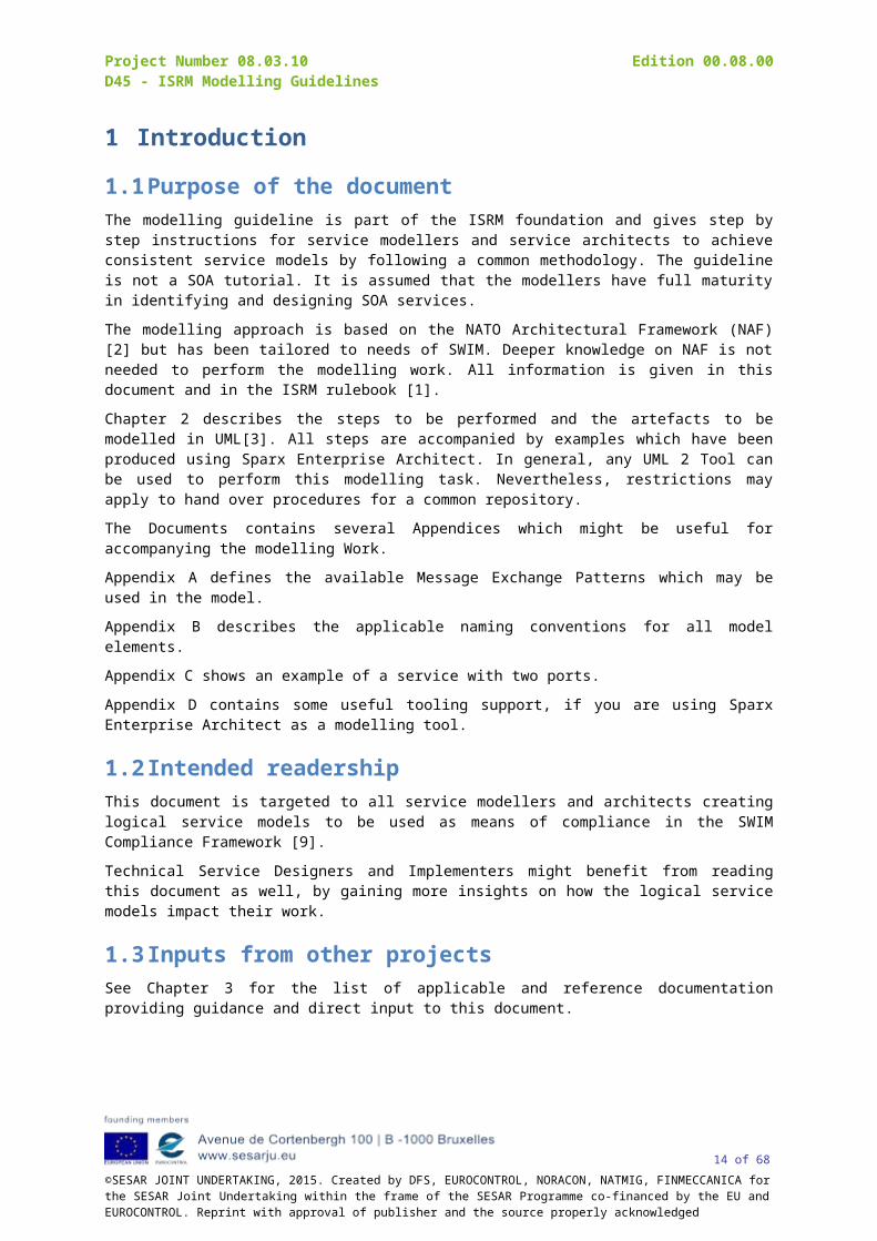
1.1 Purpose of the documentThe modelling guideline is part of the ISRM foundation and gives step by step instructions for service modellers and service architects to achieve consistent service models by following a common methodology. The guideline is not a SOA tutorial. It is assumed that the modellers have full maturity in identifying and designing SOA services.
The modelling approach is based on the NATO Architectural Framework (NAF) [2] but has been tailored to needs of SWIM. Deeper knowledge on NAF is not needed to perform the modelling work. All information is given in this document and in the ISRM rulebook [1].
Chapter 2 describes the steps to be performed and the artefacts to be modelled in UML[3]. All steps are accompanied by examples which have been produced using Sparx Enterprise Architect. In general, any UML 2 Tool can be used to perform this modelling task. Nevertheless, restrictions may apply to hand over procedures for a common repository.
The Documents contains several Appendices which might be useful for accompanying the modelling Work.
Appendix A defines the available Message Exchange Patterns which may be used in the model.
Appendix B describes the applicable naming conventions for all model elements.
Appendix C shows an example of a service with two ports.
Appendix D contains some useful tooling support, if you are using Sparx Enterprise Architect as a modelling tool.
1.2 Intended readershipThis document is targeted to all service modellers and architects creating logical service models to be used as means of compliance in the SWIM Compliance Framework [9].
Technical Service Designers and Implementers might benefit from reading this document as well, by gaining more insights on how the logical service models impact their work.
1.3 Inputs from other projectsSee Chapter 3 for the list of applicable and reference documentation providing guidance and direct input to this document.
1.4 Glossary of termsTerm Definition
Service modeller In the context of ISRM, the Service Modeller is a SOA designer expert designing ATM services to be incorporated into the ISRM.
Service architectIn the context of the ISRM, the Service architect is a SOA architect focusing on the information exchanges. Contrary to a Service modeller, the work of a service architect is often closer to the operational environment where the service will be used.
Information architectIn the context of the ISRM, the Information architect is an information modeller focusing on the modelling of the information exchanges to be supported by a service.
Table 1: Glossary and terms
10 of 53©SESAR JOINT UNDERTAKING, 2015. Created by DFS, EUROCONTROL, NORACON, NATMIG, FINMECCANICA for the SESAR Joint Undertaking within the frame of the SESAR Programme co-financed by the EU and EUROCONTROL. Reprint with approval of publisher and the source properly acknowledged
Project Number 08.03.10 Edition 00.08.00D45 - ISRM Modelling Guidelines
1.5 Acronyms and Terminology
Term Definition
AIRM ATM Information Reference Model
ATM Air Traffic Management
CLDM Consolidated Logical Data Model (AIRM component)
CR Change Request
EA Sparx Enterprise Architect modelling tool
EATMA European ATM Architecture
IA Information Architect
IER Information Exchange Requirement
IM Information Model (AIRM component)
ISRM Information Service Reference Model
IT Information Technology
NAF NATO Architecture Framework
QoS Quality of Service
SA Service Architect
SESAR Single European Sky ATM Research Programme
SJU SESAR Joint Undertaking (Agency of the European Commission)
SOA Service Oriented Architecture
SPR Safety and Performance Requirements
SWIM System Wide Information Management
SWIM-TI SWIM Technical Infrastructure
UML Unified Modelling Language
Table 2: Acronyms
11 of 53©SESAR JOINT UNDERTAKING, 2015. Created by DFS, EUROCONTROL, NORACON, NATMIG, FINMECCANICA for the SESAR Joint Undertaking within the frame of the SESAR Programme co-financed by the EU and EUROCONTROL. Reprint with approval of publisher and the source properly acknowledged

Project Number 08.03.10 Edition 00.08.00D45 - ISRM Modelling Guidelines
2 Design service
2.1 Design goalsThe main purpose of service design is to identify and design services that are relevant from a business and operational perspective and are aligned with the technical architecture. Further it shall be ensured that the services can be implemented in a way that enables the operational activities to be performed in a correct way and with the right information at hand.
To achieve this, a set of design goals have been identified that a Service Architect can use as guidance to ensure that the overall purpose is met. Below, each design goal is stated along with a set of considerations that the Service Architect should keep in mind in order to achieve the goal. It should be emphasised that these design goals and guidance are not to be interpreted as strict rules that always must be adhered to, but they are “best practice” and alignment is encouraged.
The services are governable
Services should be as coarse grained as possible to minimize the administrative burden, but fine grained enough to identify impacted ATM stakeholders (who is provider/consumer).
The services are discoverable
The services should have a clear fit into service categorisation/taxonomy. If the fit is unclear, i.e. the service fits in many places, it may be hard to reach the right target audience in the discovery process and may result in governance issues.
The services are reusable
The scope of the service should be precise enough to be able to support each specific operational scenario in a sufficient way. But at the same time it should be designed to be reusable in several contexts. During service identification the Service Architect may choose to avoid allocating the service to a specific type of stakeholder and take into consideration that the service could be provided by several stakeholders (instances) at the same time.
The services have minimal dependencies
The Service Architect should also aim to minimize inter-interface dependencies both within the same service and with other services.
It should be considered if there are functions of the service that are optional, in this case it might be a good idea to create a separate interface for these.
Non-Functional Requirements are met
It should be considered to separate interfaces with very different Non-Functional Requirements such as security-, availability-, throughput-, change rate- requirements.
The services can be feasibly implemented
Consider usage of open and widely accepted standards in order to increase the chance of broad acceptance by the ATM stakeholders.
Ensure to have a dialogue with system architects regarding the links to SWIM-TI Profiles and specifically the bindings (protocols) that should be used for implementing the service.
The services support the operational dialogue
Service operations should be designed so that they can be related to the operational activities that will make use of the service. This normally means that there should be a verb in the operations name, (see chapter B.3 for more details on naming conventions).
The Service Architect should consider sequencing/dependencies between provider/consumer processes, i.e. if there is a need for a dialogue at the operational level, this should be reflected in the operations of the service.
There is feasibility in the technical implementation
12 of 53©SESAR JOINT UNDERTAKING, 2015. Created by DFS, EUROCONTROL, NORACON, NATMIG, FINMECCANICA for the SESAR Joint Undertaking within the frame of the SESAR Programme co-financed by the EU and EUROCONTROL. Reprint with approval of publisher and the source properly acknowledged

Project Number 08.03.10 Edition 00.08.00D45 - ISRM Modelling Guidelines
Standardised message exchange patterns as described in this document shall be used as a basis when designing the operations. In addition, the context specific information should be taken into account.
Use standard data exchange models where possible to ensure maximum technical interoperability.
Loose couplings, i.e., stateless services should be promoted to minimise dependency between providers and consumers.
Thought should be given to balance number of operations vs invocation frequency, i.e. an operation which is going to be invoked very frequently can be optimised in terms of payload content while a less frequent operation could have a wider payload.
The service payload has an operational relevance
Service payload should be composed in a way that they have an operational meaning, i.e. that are (related to) information products that are output/input of activities.
The design should strive to explain the semantic meaning of the exchanged data to ensure operational interoperability among ATM stakeholders.
There is efficiency in the data distribution
Data filters should be used where applicable as a means to limit the number of operations needed and reduce the frequency and size of exchanged data.
There should be a balance between message/payload size vs distribution frequency, e.g. frequently exchanged data could be kept in small messages and in separate operations.
2.2 OutputThe output of the service design is a UML model representation of a service on a logical level. This means it is independent of implementation technologies but gives a formal description of the service interface and its behaviour. The main intended use case of this model is to serve as means of compliance for assessing technical service designs for SWIM compliance as described in [9].
The output of the service design consists of three model diagrams:
1. Service Interface Definitions
2. Service Interface Parameter Definition
3. Service event Trace Definition
It is encouraged to provide a Requirements Traceability Diagram as well, even if it is optional.
These Diagrams contain all the elements needed to support the SWIM compliance assessment.
Further, the model contains statements about the usage of certain Message Exchange Patterns (MEPs) as well as Payload descriptions compliantly traced to the AIRM.
2.2.1 Package structureAll logical services models must adhere to the same basic package structure (see Figure 1 for an Example).
Figure 1: Example project browser structure
13 of 53©SESAR JOINT UNDERTAKING, 2015. Created by DFS, EUROCONTROL, NORACON, NATMIG, FINMECCANICA for the SESAR Joint Undertaking within the frame of the SESAR Programme co-financed by the EU and EUROCONTROL. Reprint with approval of publisher and the source properly acknowledged
Project Number 08.03.10 Edition 00.08.00D45 - ISRM Modelling Guidelines
The package structure has a root package which is named after the service which contains two sub-packages which are called Diagrams and Elements
The Diagrams package should contain all of the diagrams defined for the service and the Elements package is used to store different kinds of elements that are produced as part of the definition of a service. The following can be stated for each of these packages:
Service:This package is where the service element, the interface(s) and the consumer(s) are placed.
Payload:All messages directly used as parameter types of a service interface operation should be placed in this package. This includes also the data entities used for structuring the payload.
Event Trace:All Elements of a sequence diagram for the service like life lines or interaction fragments should be placed in this package.
Requirements:If there are requirements available for the service (IERs or NFRs) they should be paced in this package.
Abbreviations:If there are abbreviations used for naming service elements, they should be paced in this package.
It is assumed that the complete package structure can be delivered as an XMI file to a repository containing all ISRM services.
Applicable RulesGR010, GR020, GR100, GR110, GR120, GR130, GR140, NC100, NC200, NC210, NC220, NC240, NC400
2.3 Steps to be performedThis chapter describes the steps to be performed in order to produce the output of the service design as aforementioned in chapter 2.2. In principle, the modeller elaborates these outputs along the process steps as shown in Figure 2. The order of the steps is not vitally important but has proved to be helpful. Especially for first time modellers this is considered to be a good guidance.
14 of 53©SESAR JOINT UNDERTAKING, 2015. Created by DFS, EUROCONTROL, NORACON, NATMIG, FINMECCANICA for the SESAR Joint Undertaking within the frame of the SESAR Programme co-financed by the EU and EUROCONTROL. Reprint with approval of publisher and the source properly acknowledged

Project Number 08.03.10 Edition 00.08.00D45 - ISRM Modelling Guidelines
Figure 2: The steps of the service design process
2.3.1 Step 1: Identify and uniquely name serviceIn step 1 the modeller focuses on the identification of a service candidate. He or she identifies the service from given sources of Information on the operational process the service should support, e.g. Information Exchange Requirements (IERs). The identified candidate service should be named uniquely.
See Appendix B.1 “Service naming conventions” for information on how to name services.
Design Goal: Merge/split criteria for ServicesDuring the identification, it is recommended to assess the identified service candidate against the existing service portfolio to determine if there is a need or opportunity to reuse and update an existing service or whether the newly identified service should result in an addition to the service portfolio. Making this decision is not a trivial process that can be automated as there are many different parameters that can be considered. The following criterion should be considered in the discussion among service architects:
Consider merging services if TRUE and consider splitting if FALSE:
15 of 53©SESAR JOINT UNDERTAKING, 2015. Created by DFS, EUROCONTROL, NORACON, NATMIG, FINMECCANICA for the SESAR Joint Undertaking within the frame of the SESAR Programme co-financed by the EU and EUROCONTROL. Reprint with approval of publisher and the source properly acknowledged
Identify and uniquely name
a service
Map Service to Requirements
Specify Ports and MEPs
Specify Interfaces
Specify Service Interface
Operations
Specify Operation
Parameters
Specify Service Payload design
Trace Service Payload to
AIRM
Specify event trace
description

Project Number 08.03.10 Edition 00.08.00D45 - ISRM Modelling Guidelines
Provided by the same actor (i.e. Node)
Have the same/similar business model (free/pay per use etc.)
Relate to the same/similar operational activities
Relate to the same Flight- / Lifecycle- Phase
Deal with same/similar information/data
Applicable RulesGR010, GR020, NC200, NC210, NC220, NC240, NC300, NC310, NC500, SM010, SM020, SM030, SM040, SM050, SM110, SM400, SM410, SM420, SM430
2.3.1.1 Create Service ElementThe service element is the fundamental building block of the logical service model. To create this element for a new service model, perform the following steps. (Examples shown in Figure 3 and Figure 4)
1. Create an interface definition diagram:
1.1. Add a UML class diagram to the Diagrams package of your service.
1.2. Name it “<Service name> Interface Definition” 1. You may optionally postfix it with further context if you need more than one of these diagrams.
1.3. Set diagram properties not to show namespaces
2. Create the Service element
2.1. Add a Class to the diagram and name it according to the service name2.
2.2. Assign the stereotype <<Service>> to the element.
3. Move the service element into the Elements/Service package.
Figure 3: Example of Service Element in Package Structure
1 The <ServiceName> represents the actual name of the service, or some shorthand of it. You should use a shorthand version if the service name is longer than 10-15 characters. If you use a shorthand version of the name, you must make sure to use the same shorthand in all the diagrams for the service. See rule NC400 in the ISRM Rulebook [11] for further clarification for this and other diagram names.
2 It should be noted that it is required not to end the name of the service with the word 'Service'. The reason for this is that the stereotype applied and visible already states that this is a service making the use of the word service as part of the name somewhat redundant.
16 of 53©SESAR JOINT UNDERTAKING, 2015. Created by DFS, EUROCONTROL, NORACON, NATMIG, FINMECCANICA for the SESAR Joint Undertaking within the frame of the SESAR Programme co-financed by the EU and EUROCONTROL. Reprint with approval of publisher and the source properly acknowledged

Project Number 08.03.10 Edition 00.08.00D45 - ISRM Modelling Guidelines
class TOBTSetting Interface ...
«Service»TargetOffBlockTimeSetting
Figure 4: Example of Interface Definition Diagram
2.3.2 Step 2: Map Service to Requirements (IER and NFR)If there are requirements available for the service, the modeller is encouraged to reference them in this model.
To support traceability to operational and non-functional requirements a class diagram shall be created. The purpose of this diagram is to reference requirements existing in other documents, not to host them as a source! Operational requirements (IER) and non-functional requirements (NFR/SPR) are treated equally in this diagram.
All requirements which justify the identified service, are created as UML Class elements with a <<Requirement>> stereotype and shall be placed in the Elements/Requirements package.
All the content that is needed to identify the requirement shall be given in the name and the note field of the <<Requirement>> element plus some special tagged values.
The <<Requirement>> element shall therefore contain the following content:
Name:Name of the Requirement as given in the original source or best fit if requirement is derived from text.
Notes:The original or derived text of the requirement. (This is optional)
Tag: refLabelValue: The ref tag is intended to contain a reference string (e.g. Number or ID) that allows for identifying the requirement at its source.
Tag: refSourceValue: The Title of the document containing the requirement
Tag: refURLValue: URL where a digital copy of the source document can be found (optional)
Tag: reqType:Value: The type of the requirement. There are three possible values:
o Operational requirement
o Information exchange requirement
o Safety and performance requirement3
Applicable RulesGR010, GR020, NC200, NC210, NC240, NC500, SM030, SM040, SM050, SM100, SM400, SM410, SM420, SM430
The following steps need to be performed to create a valid requirements tracing:
3 To be used for Non Functional requirements (NFR)
17 of 53©SESAR JOINT UNDERTAKING, 2015. Created by DFS, EUROCONTROL, NORACON, NATMIG, FINMECCANICA for the SESAR Joint Undertaking within the frame of the SESAR Programme co-financed by the EU and EUROCONTROL. Reprint with approval of publisher and the source properly acknowledged

Project Number 08.03.10 Edition 00.08.00D45 - ISRM Modelling Guidelines
1. Create UML class diagram in the Diagrams package of your service.
2. Name it “<Service name> Requirements Traceability4”.
3. Add the <<Service>> Element from the Elements/Service package to the created diagram.
4. Add Class Elements with stereotype <<Requirement>> to the diagram and place them into the Elements/Requirements package
a. Give the Element the name of the requirement
b. Add the requirement text to the notes section.(optional)
c. Add a tagged value refLabel with the identifier of the requirement
d. Add a tagged value refSource with the title of the source document.
e. Add a tagged value refURL with a link to the source document. (optional)
f. Add a tagged value reqType indicating the type of the requirement
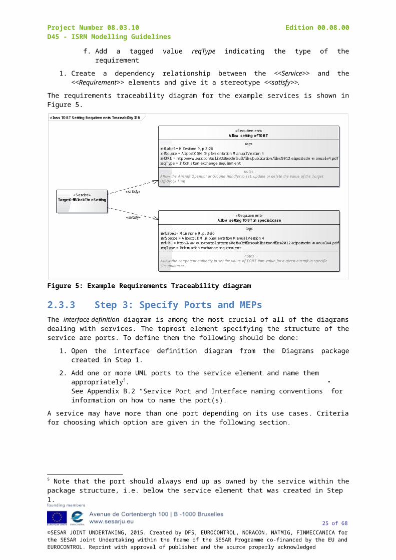
1. Create a dependency relationship between the <<Service>> and the <<Requirement>> elements and give it a stereotype <<satisfy>>.
The requirements traceability diagram for the example services is shown in Figure 5.
class TOBT Setting Requirements Traceability IER
«Service»TargetOffBlockTimeSetting
«Requirement»Allow setting of TOBT
tagsrefLabel = Milestone 9, p.3-26refSource = Airport CDM Implementation Manual Version 4refURL = http://www.eurocontrol.int/sites/default/files/publication/fi les/2012-airport-cdm-manual-v4.pdfreqType = Information exchange requirement
notesAllow the Aircraft Operator or Ground Handler to set, update or delete the value of the TargetOff-Block Time
«Requirement»Allow setting TOBT in special case
tagsrefLabel = Milestone 9, p. 3-26refSource = Airport CDM Implementation Manual Version 4refURL = http://www.eurocontrol.int/sites/default/files/publication/fi les/2012-airport-cdm-manual-v4.pdfreqType = Information exchange requirement
notesAllow the competent authority to set the value of TOBT time value for a given aircraft in specificcircumstances.
«satisfy»
«satisfy»
Figure 5: Example Requirements Traceability diagram
2.3.3 Step 3: Specify Ports and MEPsThe interface definition diagram is among the most crucial of all of the diagrams dealing with services. The topmost element specifying the structure of the service are ports. To define them the following should be done:
1. Open the interface definition diagram from the Diagrams package created in Step 1.
4 You may decide to split the traceability of IERs and NFRs into two diagrams. In this case add the postfix IER or NFR to the name of the diagrams respectively.
18 of 53©SESAR JOINT UNDERTAKING, 2015. Created by DFS, EUROCONTROL, NORACON, NATMIG, FINMECCANICA for the SESAR Joint Undertaking within the frame of the SESAR Programme co-financed by the EU and EUROCONTROL. Reprint with approval of publisher and the source properly acknowledged

Project Number 08.03.10 Edition 00.08.00D45 - ISRM Modelling Guidelines
2. Add one or more UML ports to the service element and name them appropriately5. See Appendix B.2 “Service Port and Interface naming conventions” for information on how to name the port(s).
A service may have more than one port depending on its use cases. Criteria for choosing which option are given in the following section.
Merge/split criteria for Service PortsWhen deciding whether to create a new port or to merge two ports the following criteria can be used by the service architects in their discussion:
Consider merging service ports if TRUE and consider splitting if FALSE:
Relate to the same provider operational activity
Have similar non-functional requirements (performance, security etc.)
Have same/similar operations
Operations have a sequential dependency to each other
Deal with same/similar information/data
Applicable RulesGR010, GR020, NC200, NC210, NC220, NC240, SM020, SM030, SM040, SM050, SM120, SM130
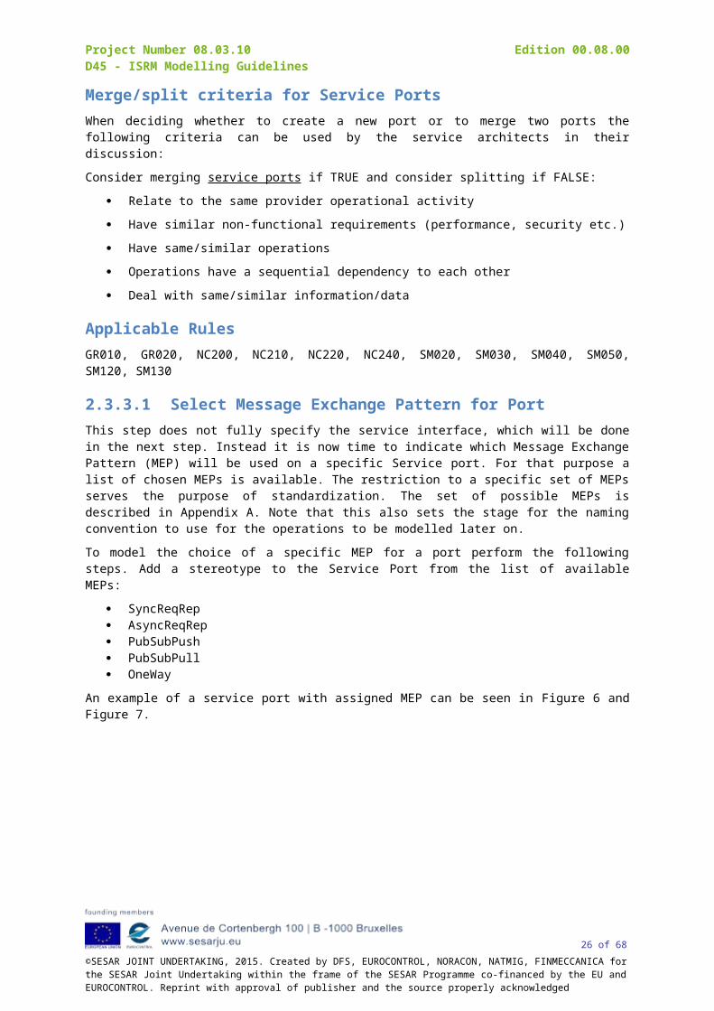
2.3.3.1 Select Message Exchange Pattern for PortThis step does not fully specify the service interface, which will be done in the next step. Instead it is now time to indicate which Message Exchange Pattern (MEP) will be used on a specific Service port. For that purpose a list of chosen MEPs is available. The restriction to a specific set of MEPs serves the purpose of standardization. The set of possible MEPs is described in Appendix A. Note that this also sets the stage for the naming convention to use for the operations to be modelled later on.
To model the choice of a specific MEP for a port perform the following steps. Add a stereotype to the Service Port from the list of available MEPs:
SyncReqRep AsyncReqRep PubSubPush PubSubPull OneWay
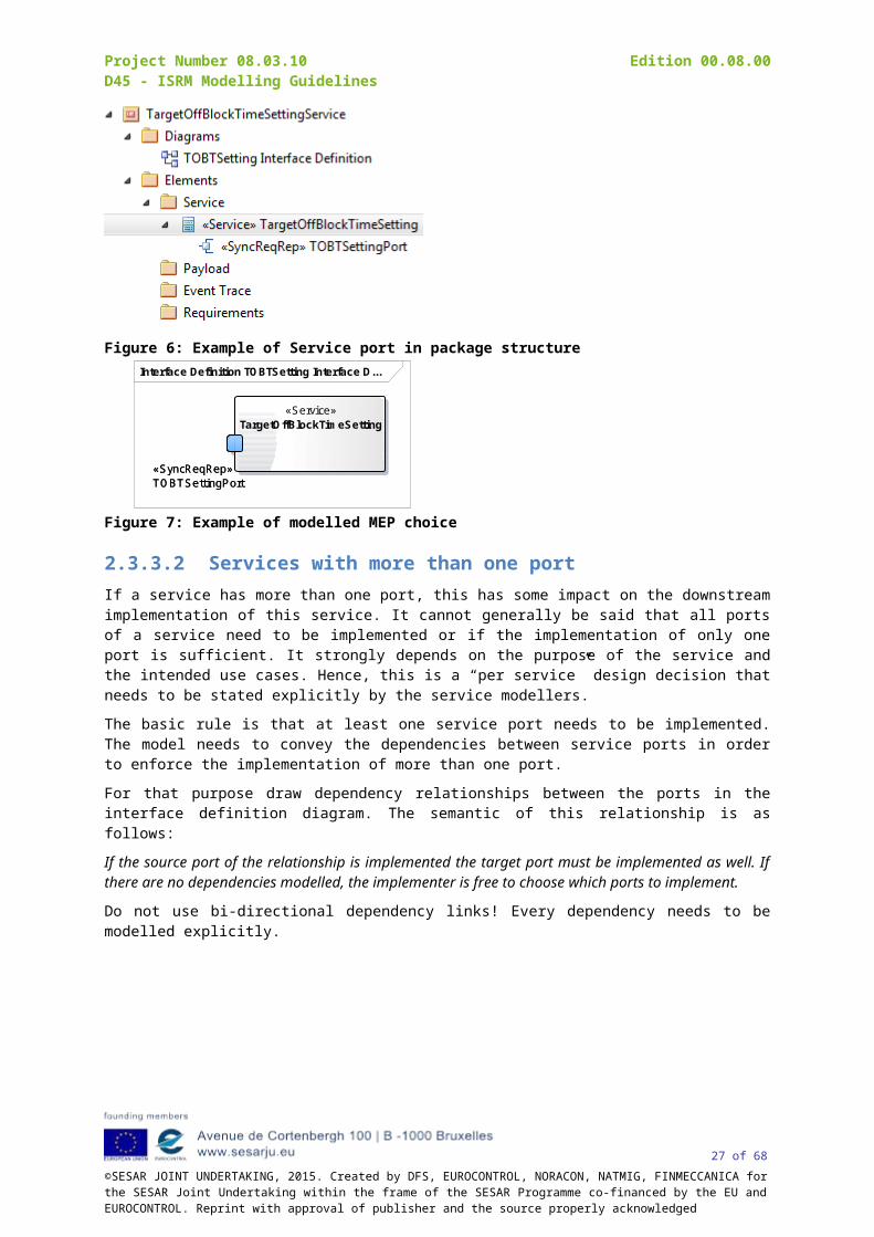
An example of a service port with assigned MEP can be seen in Figure 6 and Figure 7.
Figure 6: Example of Service port in package structure
5 Note that the port should always end up as owned by the service within the package structure, i.e. below the service element that was created in Step 1.
19 of 53©SESAR JOINT UNDERTAKING, 2015. Created by DFS, EUROCONTROL, NORACON, NATMIG, FINMECCANICA for the SESAR Joint Undertaking within the frame of the SESAR Programme co-financed by the EU and EUROCONTROL. Reprint with approval of publisher and the source properly acknowledged

Project Number 08.03.10 Edition 00.08.00D45 - ISRM Modelling Guidelines
Interface Definition TOBTSetting Interface D...
«SyncReqRep»TOBTSettingPort
«Service»TargetOffBlockTimeSetting
«SyncReqRep»TOBTSettingPort
Figure 7: Example of modelled MEP choice
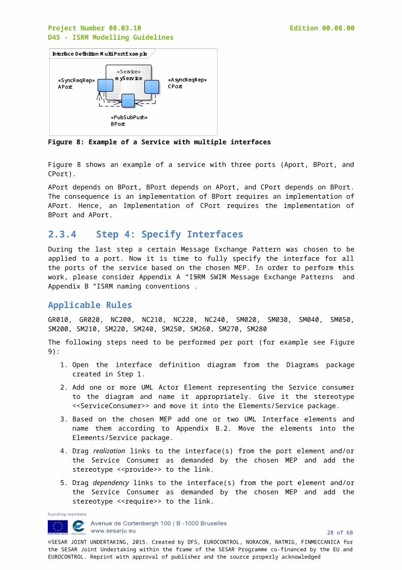
2.3.3.2 Services with more than one portIf a service has more than one port, this has some impact on the downstream implementation of this service. It cannot generally be said that all ports of a service need to be implemented or if the implementation of only one port is sufficient. It strongly depends on the purpose of the service and the intended use cases. Hence, this is a “per service” design decision that needs to be stated explicitly by the service modellers.
The basic rule is that at least one service port needs to be implemented. The model needs to convey the dependencies between service ports in order to enforce the implementation of more than one port.
For that purpose draw dependency relationships between the ports in the interface definition diagram. The semantic of this relationship is as follows:
If the source port of the relationship is implemented the target port must be implemented as well. If there are no dependencies modelled, the implementer is free to choose which ports to implement.
Do not use bi-directional dependency links! Every dependency needs to be modelled explicitly.
Interface Definition Multi Port Example
«SyncReqRep»APort
«PubSubPush»BPort
«AsyncReqRep»CPort
«Service»myServ ice«SyncReqRep»
APort
«PubSubPush»BPort
«AsyncReqRep»CPort
Figure 8: Example of a Service with multiple interfaces
Figure 8 shows an example of a service with three ports (Aport, BPort, and CPort).
APort depends on BPort, BPort depends on APort, and CPort depends on BPort. The consequence is an implementation of BPort requires an implementation of APort. Hence, an Implementation of CPort requires the implementation of BPort and APort.
2.3.4 Step 4: Specify Interfaces During the last step a certain Message Exchange Pattern was chosen to be applied to a port. Now it is time to fully specify the interface for all the ports of the service based on the chosen MEP. In order to perform this work, please consider Appendix A “ISRM SWIM Message Exchange Patterns” and Appendix B “ISRM naming conventions”.
Applicable RulesGR010, GR020, NC200, NC210, NC220, NC240, SM020, SM030, SM040, SM050, SM200, SM210, SM220, SM240, SM250, SM260, SM270, SM280
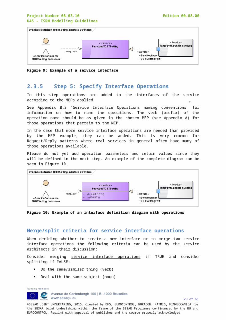
The following steps need to be performed per port (for example see Figure 9):
20 of 53©SESAR JOINT UNDERTAKING, 2015. Created by DFS, EUROCONTROL, NORACON, NATMIG, FINMECCANICA for the SESAR Joint Undertaking within the frame of the SESAR Programme co-financed by the EU and EUROCONTROL. Reprint with approval of publisher and the source properly acknowledged

Project Number 08.03.10 Edition 00.08.00D45 - ISRM Modelling Guidelines
1. Open the interface definition diagram from the Diagrams package created in Step 1.
2. Add one or more UML Actor Element representing the Service consumer to the diagram and name it appropriately. Give it the stereotype <<ServiceConsumer>> and move it into the Elements/Service package.
3. Based on the chosen MEP add one or two UML Interface elements and name them according to Appendix B.2. Move the elements into the Elements/Service package.
4. Drag realization links to the interface(s) from the port element and/or the Service Consumer as demanded by the chosen MEP and add the stereotype <<provide>> to the link.
5. Drag dependency links to the interface(s) from the port element and/or the Service Consumer as demanded by the chosen MEP and add the stereotype <<require>> to the link.
Interface Definition TOBTSetting Interface Definition
«SyncReqRep»TOBTSettingPort
«Service»TargetOffBlockTimeSetting
«SyncReqRep»TOBTSettingPort
«Serv iceConsumer»TOBTSetting consumer
«interface»Prov idedTOBTSetting
«require» «provide»
Figure 9: Example of a service interface
2.3.5 Step 5: Specify Interface Operations In this step operations are added to the interfaces of the service according to the MEPs applied
See Appendix B.3 “Service Interface Operations naming conventions” for information on how to name the operations. The verb (prefix) of the operation name should be as given in the chosen MEP (see Appendix A) for those operations that pertain to the MEP.
In the case that more service interface operations are needed than provided by the MEP example, they can be added. This is very common for Request/Reply patterns where real services in general often have many of those operations available.
Please do not yet add operation parameters and return values since they will be defined in the next step. An example of the complete diagram can be seen in Figure 10.
Interface Definition TOBTSetting Interface Definition
«SyncReqRep»TOBTSettingPort
«Service»TargetOffBlockTimeSetting
«SyncReqRep»TOBTSettingPort
«Serv iceConsumer»TOBTSetting consumer
«interface»Prov idedTOBTSetting
+ deleteTOBT()+ setTOBT()
«require» «provide»
Figure 10: Example of an interface definition diagram with operations
Merge/split criteria for service interface operationsWhen deciding whether to create a new interface or to merge two service interface operations the following criteria can be used by the service architects in their discussion:
Consider merging service interface operations if TRUE and consider splitting if FALSE:
Do the same/similar thing (verb)
Deal with the same subject (noun)
21 of 53©SESAR JOINT UNDERTAKING, 2015. Created by DFS, EUROCONTROL, NORACON, NATMIG, FINMECCANICA for the SESAR Joint Undertaking within the frame of the SESAR Programme co-financed by the EU and EUROCONTROL. Reprint with approval of publisher and the source properly acknowledged

Project Number 08.03.10 Edition 00.08.00D45 - ISRM Modelling Guidelines
Similar characteristics on the payload (data format, delivery pattern, persistency etc.)
Are always invoked in the same sequence (within one interface)
Applicable RulesGR010, GR020, NC200, NC210, NC230, NC240, NC320, SM020, SM030, SM050, SM576, SM240, SM250, SM260, SM270, SM280
2.3.6 Step 6: Specify Operation ParametersThe types of the input and output parameters for operations defined in the interface of the service shall be modelled as separate <<Message>> elements. They will be detailed into actual payloads in the next step. The relationship between payload and service interface operation is shown in Figure11Error: Reference source not found. Please note, that this is only an illustrative diagram which is not part of the actual service model! The Interface and the Message elements do not have to be shown in one diagram. It is further not necessary to show parameter names in the diagrams, only types.
Applicable RulesGR010, GR020, NC200, NC210, NC220, NC240, NC500, SM020, SM030, SM040, SM050, SM230, SM240, SM250, SM260, SM270, SM280, SM300, SM400, SM410, SM420, SM430
class
TOBT Setting Interface Parameter Definition for set TOBT
TOBTSetting Interface Definition
«interface»Prov idedTOBTSetting
+ deleteTOBT(TOBTDeleteRequest): TOBTDeleteResponse+ setTOBT(TOBTSettingRequest): TOBTSettingResponse
«Message»TOBTSettingRequest
«Message»TOBTSettingResponse
Figure 11: Illustrative diagram showing service operation parameters and their payload elements.The following steps need to be done:
1. Create one (or more) class diagram(s) in the Elements/Diagrams package and name it “<ServiceName> Interface Parameter Definition”6, with an optional postfix text to denote further context, if more than one diagram is needed.
2. Create UML Class Elements for each Operation parameter needed and name them according to Appendix B.4 “Messages/Service Interface Parameters naming conventions”.
6 See rule NC400 in the ISRM Rulebook [1]
22 of 53©SESAR JOINT UNDERTAKING, 2015. Created by DFS, EUROCONTROL, NORACON, NATMIG, FINMECCANICA for the SESAR Joint Undertaking within the frame of the SESAR Programme co-financed by the EU and EUROCONTROL. Reprint with approval of publisher and the source properly acknowledged

Project Number 08.03.10 Edition 00.08.00D45 - ISRM Modelling Guidelines
3. Add the stereotype <<Message>> to the Elements and move them to the Elements/Payload package.
4. Add the created <<Message>> elements as parameter types for input, output or return type to your interface operations.
2.3.7 Step 7: Specify Service Payload design The design of the service payload concerns the formal representation of the content and structure of the input and output parameters of each service interface operation.
The payload is to be modelled as a tree structure, where the root is the message used as parameter in the service interface operation as the example in Figure 12.
class TOBT Setting Interface Parameter Definition for set TOBT
«Message»TOBTSettingRequest
«DataEntity»OffBlockReady
+ targetTime
«DataEntity»FlightID
«Message»TOBTSettingResponse
«DataEntity»A-CDMServ iceResponseStatus
+ reasonForRejection: CharacterString+ status: CharacterString
Details of this DataEntity are explained separately.
+fl ightID 1+offBlockReady 1 +responseStatus 1
Figure 12: Example of a payload structure
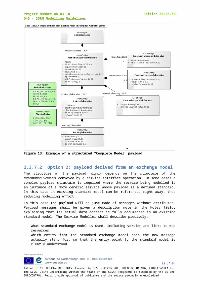
Two design options can be chosen:
1. “Complete Model” approach: The service payload cannot rely on an available exchange model, therefore it must be modelled ex-novo or a portion of AIRM CLDM is already fit for shaping the service payload, therefore the payload can be built by sub-setting the CLDM.
2. “Use standard” approach: Refer to an existing exchange model (like AIXM, FIXM, etc…) which already contains a complete representation for the payload.
These approaches are explained in the next sections.
Applicable RulesGR010, GR020, NC200, NC210, NC220, NC230, NC240, SM010, SM020, SM030, SM040, SM050, SM300, SM310, SM320,SM330, ,SM340, SM350, SM370,
2.3.7.1 Option 1: “Complete Model” approachThis approach can be used to create a payload model from scratch or in some cases the payload may be built by manually recreating a portion of the AIRM CLDM. It is up to the modeller to decide which approach suites best, but since the payload will have to be traced to the AIRM to ensure semantic interoperability (see Step 8: Trace Service Payload to AIRM) the reuse of AIRM structures can save some work.
23 of 53©SESAR JOINT UNDERTAKING, 2015. Created by DFS, EUROCONTROL, NORACON, NATMIG, FINMECCANICA for the SESAR Joint Undertaking within the frame of the SESAR Programme co-financed by the EU and EUROCONTROL. Reprint with approval of publisher and the source properly acknowledged

Project Number 08.03.10 Edition 00.08.00D45 - ISRM Modelling Guidelines
The payload model is built by Classes stereotyped as <<Message>>7 or <<DataEntity>> and <<enumeration>> elements. You should consider naming conventions according to Appendix B.4. The elements shall be placed in the Elements/Payload package.
Please note that attributes shall be named in lowerCamelCase8. The type of the attribute shall be normally left blank (<none>), unless:
a. the attribute is an enumerated value: in this case the corresponding <<enumeration>> shall be indicated as type for the attribute;
b. the attribute is out of the scope of AIRM, it shall be given a type chosen among base and foundation types available in the AIRM.
Relationships between <<Message>> and <<DataEntity>> or between <<DataEntity>> and <<DataEntity>> elements shall be created using UML compositions. You shall add a role name for the target role of the compostion. Attribute multiplicity should be set as well.
An example of a fully defined structured payload model using the “Complete Model” approach is shown below in Figure 13:
class ArrivalManagementInformation Interface Parameter Definition Arriv al Sequence
«DataEntity»ProposedProcedureInformation
+ advisedHoldingProcedure [0..1]+ advisedSTAR [0..1]+ advisedTransition [0..1]
«Message»ArrivalSequence
«DataEntity»RunwayAssignmentInformation
+ assignedRunwayDirection+ landingSequencePosition [0..1]
A
«DataEntity»Adv isoryInformation
+ routeAdvisory [0..1]+ speedAdvisory [0..1]+ constraintCTA [0..1]+ timeToGainOrLose [0..1]
«DataEntity»MeteringInformation
+ pointName+ pointUsage: ArrivalPointUsage+ planningStatus: PlanningStatus+ AMANPlannedTimeOver+ delayAtPoint [0..1]
«DataEntity»DepartureManagementInformation
+ departureAerodrome+ timeToLoseOnTheGround [0..1]
«DataEntity»ArrivalManagementInformation
+ flightID+ AMANPlannedThresholdTime+ sequenceNumber [0..1]+ arrivalDelay [0..1]+ delayShare [0..1]+ arrivalManagementHandlingIndicator [0..*]+ typeOfAircraft [0..1]+ wakeTurbulenceCategory [0..1]+ AMANStrategy [0..1]
«enumeration»ArrivalPointUsage
INITIAL_METERING_FIX COORDINATION METERING_FIX INITIAL_APPROACH_FIX FINAL_APPROACH_FIX OTHER
«enumeration»PlanningStatus
ESTIMATED_TIME TARGET_TIME CONTROLLED_TIME
+runwayAssignment 0..1
+sequenceEntries 0..*
+proposedProcedure
0..1
+advisoryInformation 1
+meteringInformation 0..*
+departureAirport
0..1
Figure 13: Example of a structured “Complete Model” payload
7 These are the elements already created in the previous step.
8 https://en.wikipedia.org/wiki/CamelCase
24 of 53©SESAR JOINT UNDERTAKING, 2015. Created by DFS, EUROCONTROL, NORACON, NATMIG, FINMECCANICA for the SESAR Joint Undertaking within the frame of the SESAR Programme co-financed by the EU and EUROCONTROL. Reprint with approval of publisher and the source properly acknowledged
Project Number 08.03.10 Edition 00.08.00D45 - ISRM Modelling Guidelines
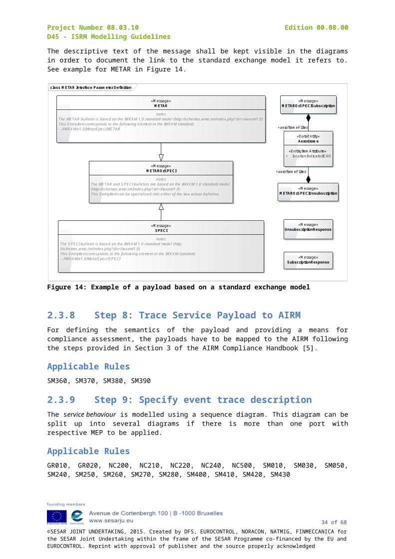
2.3.7.2 Option 2: payload derived from an exchange modelThe structure of the payload highly depends on the structure of the Information Elements conveyed by a service interface operation. In some cases a complex payload structure is required where the service being modelled is an instance of a more generic service whose payload is a defined standard. In this case an existing standard model can be referenced right away, thus reducing modelling effort.
In this case the payload will be just made of messages without attributes. Payload messages shall be given a description note in the Notes field, explaining that its actual data content is fully documented in an existing standard model. The Service Modeller shall describe precisely:
- what standard exchange model is used, including version and links to web resources;- which entity from the standard exchange model does the new message actually stand for, so that
the entry point to the standard model is clearly understood.
The descriptive text of the message shall be kept visible in the diagrams in order to document the link to the standard exchange model it refers to. See example for METAR in Figure 14.
class METAR Interface Parameter Definition
«Message»UnsubscriptionResponse
«Message»METAROrSPECISubscription
«Message»METAROrSPECIUnsubscription
«Message»SubscriptionResponse
«Message»METAR
notesThe METAR bul letin is based on the IWXXM 1.0 standard model (http://schemas.wmo.int/index.php?dir=/iwxxm/1.0)This EntityItem corresponds to the fol lowing element in the IWXXM standard:- ./iWXXM/v1.0/MetarSpeci/METAR
«Message»METAROrSPECI
notesThe METAR and SPECI bulletins are based on the IWXXM 1.0 standard model(http://schemas.wmo.int/index.php?dir=/iwxxm/1.0)This EntityItem can be special ized into either of the two actual bulletins.
«Message»SPECI
notesThe SPECI bulletin is based on the IWXXM 1.0 standard model (http://schemas.wmo.int/index.php?dir=/iwxxm/1.0)This EntityItem corresponds to the fol lowing element in the IWXXM standard:- ./iWXXM/v1.0/MetarSpeci/SPECI
«DataEntity»Aerodrome
«EntityItemAttribute»+ locationIndicatorICAO
+aeroframeFilter
+aeroframeFilter
Figure 14: Example of a payload based on a standard exchange model
2.3.8 Step 8: Trace Service Payload to AIRM For defining the semantics of the payload and providing a means for compliance assessment, the payloads have to be mapped to the AIRM following the steps provided in Section 3 of the AIRM Compliance Handbook [5].
Applicable RulesSM360, SM370, SM380, SM390
2.3.9 Step 9: Specify event trace description The service behaviour is modelled using a sequence diagram. This diagram can be split up into several diagrams if there is more than one port with respective MEP to be applied.
25 of 53©SESAR JOINT UNDERTAKING, 2015. Created by DFS, EUROCONTROL, NORACON, NATMIG, FINMECCANICA for the SESAR Joint Undertaking within the frame of the SESAR Programme co-financed by the EU and EUROCONTROL. Reprint with approval of publisher and the source properly acknowledged
Project Number 08.03.10 Edition 00.08.00D45 - ISRM Modelling Guidelines
Applicable RulesGR010, GR020, NC200, NC210, NC220, NC240, NC500, SM010, SM030, SM050, SM240, SM250, SM260, SM270, SM280, SM400, SM410, SM420, SM430
1. Create a Sequence diagram called “<ServiceName> Event Trace Description” in the Diagrams package.
2. Add the Service element together with the relevant port and the relevant service consumer from the Elements/Services package onto the diagram. (see Figure 15 for example)
sd TOBT Ev ent Trace Description
«Service»
TargetOffBlockTimeSetting
«ServiceConsumer»TOBTSetting consumer TOBTSettingPort
Figure 15: Example of Sequence Diagram
3. Draw Messages from the Consumer to the lifeline of the service port representing the operations defined in the service interface. Make sure to correctly indicating synchronous or asynchronous call types, depending on chosen MEP.
sd TOBT Ev ent Trace Description
«Service»
TargetOffBlockTimeSetting«ServiceConsumer»
TOBTSetting consumer TOBTSettingPort
setTOBT(TOBTSettingRequest): TOBTSettingResponse
Figure 16: Example of Sequence Diagram with message
26 of 53©SESAR JOINT UNDERTAKING, 2015. Created by DFS, EUROCONTROL, NORACON, NATMIG, FINMECCANICA for the SESAR Joint Undertaking within the frame of the SESAR Programme co-financed by the EU and EUROCONTROL. Reprint with approval of publisher and the source properly acknowledged
Project Number 08.03.10 Edition 00.08.00D45 - ISRM Modelling Guidelines
4. In case it is desirable to identify different groups or possibilities in the same diagram the UML element Fragment can be used. It should be noted that fragments are distinct elements and they must therefore always be named in order to keep them distinct. Further they should be kept in the Elements/Event Trace package.
sd TOBT Ev ent Trace Description
«Service»TargetOffBlockTimeSetting
«ServiceConsumer»TOBTSetting consumer TOBTSettingPort
opt Set request
opt Delete request
deleteTOBT(TOBTDeleteRequest): TOBTDeleteResponse
setTOBT(TOBTSettingRequest): TOBTSettingResponse
Figure 17: Example of Sequence Diagram with fragments
27 of 53©SESAR JOINT UNDERTAKING, 2015. Created by DFS, EUROCONTROL, NORACON, NATMIG, FINMECCANICA for the SESAR Joint Undertaking within the frame of the SESAR Programme co-financed by the EU and EUROCONTROL. Reprint with approval of publisher and the source properly acknowledged
Project Number 08.03.10 Edition 00.08.00D45 - ISRM Modelling Guidelines
3 References[1] 08.03.10, ISRM Foundation Rulebook, D45, 00.08.00, 31/05/2016
[2] NATO ARCHITECTURE FRAMEWORK Version 3, 22/05/2013
[3] "UML® Resource Page." Object Management Group. N.p., n.d. Web. 26 May 2013, http://uml.org/
[4] 08.01.03, AIRM Foundation Rulebook, D42, 00.08.00 31/05/2016
[5] 08.01.03, AIRM Compliance Handbook, 00.01.03, 26/02/2016
[6] 08.01.01, AIRM Compliance Report, D49, 00.01.01, 22/03/2016
[7] 14.01.03, SWIM Profiles for Step 3.1, D38, 17/12/2015
[8] 08.01.01, AIRM Governance Handbook, 01.00.06, 24/07/2014
[9] 08.01.01, SWIM Compliance Framework Criteria, D49, 00.01.01, 22/03/2016
[10]08.03.10, ISRM Foundation Primer, D45, 00.08.00, 31/05/2016
28 of 53©SESAR JOINT UNDERTAKING, 2015. Created by DFS, EUROCONTROL, NORACON, NATMIG, FINMECCANICA for the SESAR Joint Undertaking within the frame of the SESAR Programme co-financed by the EU and EUROCONTROL. Reprint with approval of publisher and the source properly acknowledged
Project Number 08.03.10 Edition 00.08.00D45 - ISRM Modelling Guidelines
Appendix A ISRM SWIM Message Exchange PatternsISRM identifies a set of SWIM Message Exchange Patterns (MEPs). These are defined on a logical level and can be translated into technical MEPs defined by SWIM TI profiles in Appendix F of [9] and in [7].
The Service Modeller will have to decide which of the different MEPs described below the interface will have to implement. The choice shall in general be motivated by operational requirements.
A.1 Synchronous request/replysd sync req/rep Event Trace Description
«ServiceConsumer»serviceConsumer
«Service»ServiceName
ServicePort
request(XXXRequest): XXXReply
Figure 18: Synchronous request/reply MEP Event Trace diagramFigure 18 shows a synchronous operation based on the definition of an operation called request with an XXXRequest parameter and an XXXReply return parameter. This can be used to set something on the Provider side or to get something from the Provider.
class sync req/rep Interface Definition
«Serv iceConsumer»serv iceConsumer
«interface»XXXProv ider
+ request(XXXRequest): XXXReply
«SyncReqRep»ServicePort
«Service»Serv iceName
«SyncReqRep»ServicePort
«require»«provide»
Figure 19: Synchronous request/reply MEP Interface Definition diagram
29 of 53©SESAR JOINT UNDERTAKING, 2015. Created by DFS, EUROCONTROL, NORACON, NATMIG, FINMECCANICA for the SESAR Joint Undertaking within the frame of the SESAR Programme co-financed by the EU and EUROCONTROL. Reprint with approval of publisher and the source properly acknowledged

Project Number 08.03.10 Edition 00.08.00D45 - ISRM Modelling Guidelines
A.2 Asynchronous request/replysd async req/rep Event Trace Description
«Service»ServiceName
«ServiceConsumer»serviceConsumer ServicePort
request(XXXRequest)
reply(XXXReply)
Figure 20: Asynchronous request/reply MEP Event Trace diagramFigure 20 shows the asynchronous equivalent of the synchronous MEP described previously. The main difference is, that the Service Consumer must provide an Interface Operation reply, which will be invoked by the Service Provider in order to send back the requested data.
class async req/rep Interface Definition
«interface»XXXProv ider
+ request(XXXRequest): void
«interface»XXXConsumer
+ reply(XXXReply): void
«AsyncReqRep»ServicePort
«Service»Serv iceName
«AsyncReqRep»ServicePort
«Serv iceConsumer»serv iceConsumer
«require»
«provide»
«provide»
«require»
Figure 21: Asynchronous request/reply MEP Interface Definition diagram
30 of 53©SESAR JOINT UNDERTAKING, 2015. Created by DFS, EUROCONTROL, NORACON, NATMIG, FINMECCANICA for the SESAR Joint Undertaking within the frame of the SESAR Programme co-financed by the EU and EUROCONTROL. Reprint with approval of publisher and the source properly acknowledged

Project Number 08.03.10 Edition 00.08.00D45 - ISRM Modelling Guidelines
A.3 Publish/Subscribe Pushsd pub/sub push Ev ent Trace Description
«Service»
ServiceName
«ServiceConsumer»serviceConsumer ServicePort
loop Data Publication
opt Unsubscription
subscribe(XXXSubscription): SubscriptionResponse
unsubscribe(XXXUnsubscription):UnsubscriptionResponse
publish(XXXPublication)
Figure 22: Publish/Subscribe Push MEP Event Trace diagramFigure 22 shows the Publish/Subscribe Push MEP.
In this MEP the Service Consumer subscribes to some Data available at the Service Provider by calling the subscribe operation. The XXXSubscription parameter may include information about what the Consumer is interested in (e.g. Filter Rules etc.).
Whenever Data is available the Provider sends that Data to the subscribed Consumer via the publish operation. This operation is part of the Interface Definition provided by the Consumer.
The Consumer can unsubscribe from the Data by calling unsubscribe.
31 of 53©SESAR JOINT UNDERTAKING, 2015. Created by DFS, EUROCONTROL, NORACON, NATMIG, FINMECCANICA for the SESAR Joint Undertaking within the frame of the SESAR Programme co-financed by the EU and EUROCONTROL. Reprint with approval of publisher and the source properly acknowledged

Project Number 08.03.10 Edition 00.08.00D45 - ISRM Modelling Guidelines
class pub/sub push Interface Definition
«PubSubPush»ServicePort
«Service»Serv iceName
«PubSubPush»ServicePort
«Serv iceConsumer»serv iceConsumer
«ServiceInterfaceDefinition»XXXSubscriber
+ publish(XXXPublication): void
«interface»XXXPublisher
+ subscribe(XXXSubscription): SubscriptionResponse+ unsubscribe(XXXUnsubscription): UnsubscriptionResponse
«provide»«require»
«provide»«require»
Figure 23: Publish/Subscribe Push MEP Interface Definition diagram
A.4 Publish/Subscribe Pullsd pub/sub pull Ev ent Trace Description
«ServiceConsumer»serviceConsumer
«Service»
ServiceName
ServicePort
loop Data Publication
opt Unsubscription
unsubscribe(XXXUnsubscription):UnsubscriptionResponse
pull(XXXRequest): XXXReply
subscribe(XXXSubscription): SubscriptionResponse
Figure 24: Publish/Subscribe Pull MEP Event Trace diagramFigure 24 shows Publish/Subscribe Pull MEP.
The main difference to the Publish/Subscribe Push MEP is, that the Consumer does not have to provide an Interface. The consumer has to request the Data actively by calling the pull operation of the service Provider.
32 of 53©SESAR JOINT UNDERTAKING, 2015. Created by DFS, EUROCONTROL, NORACON, NATMIG, FINMECCANICA for the SESAR Joint Undertaking within the frame of the SESAR Programme co-financed by the EU and EUROCONTROL. Reprint with approval of publisher and the source properly acknowledged
Project Number 08.03.10 Edition 00.08.00D45 - ISRM Modelling Guidelines
The main idea of this pattern is to give the Service Provider some awareness about the interest of Service Consumers.
class pub/sub pull Interface Definition
«interface»XXXPublisher
+ pull(XXXRequest): XXXReply+ subscribe(XXXSubscription): SubscriptionResponse+ unsubscribe(XXXUnsubscription): UnsubscriptionResponse
«PubSubPull»ServicePort
«Service»Serv iceName
«PubSubPull»ServicePort«Serv iceConsumer»
serv iceConsumer
«provide»«require»
Figure 25: Publish/Subscribe Pull MEP Interface Definition diagram
A.5 One Waysd one way Ev ent Ttrace Description
«Service»ServiceName
«ServiceConsumer»serviceConsumer ServicePort
post(XXXNotification)
Figure 26: One Way MEP Event Trace diagramFigure 26 shows the One Way MEP.
This is a special case of the Request/Reply patterns without a response from the Service Provider.
class one way Interface Definition
«interface»XXXListener
+ post(XXXNotification): void
«OneWay»ServicePort
«Service»Serv iceName
«OneWay»ServicePort«Serv iceConsumer»
serv iceConsumer
«provide»«require»
Figure 27: One Way MEP Interface Definition diagram
33 of 53©SESAR JOINT UNDERTAKING, 2015. Created by DFS, EUROCONTROL, NORACON, NATMIG, FINMECCANICA for the SESAR Joint Undertaking within the frame of the SESAR Programme co-financed by the EU and EUROCONTROL. Reprint with approval of publisher and the source properly acknowledged
Project Number 08.03.10 Edition 00.08.00D45 - ISRM Modelling Guidelines
Appendix B ISRM naming conventionsThe naming conventions presented in this section are recommendations to service architects and are currently not mandated. Mandatory naming convention are given in section 2.2 of the ISRM Foundation Rulebook [4].
It is recommended that the SA endeavours to use natural language in the naming of elements in order to make the model comprehensible by people that are not used to modelling notations. This is particularly important for services that have a strong connection to operational concepts.
The naming conventions have been shaped in order to give a quick insight to the viewer of the element as to what it does and what it is. I.e. in most cases this will be a combination of verbs and nouns. The aim is to make the element comprehensible on its own without having to look at the related elements in the model. This is important because sometimes the elements are presented in isolation or in a partial context despite the fact that the ISRM is a model-based architecture and should normally be viewed in a whole-of-model perspective. I.e. an element is presented with all its relations. The effect of this on the element naming is that some parts will be repeated or similar throughout the names of related elements.
The style of element names in the ISRM model uses UpperCamelCase9 for all names except the name of operations, attributes, and parameters which uses the lowerCamelCase. This means that all names are written in one word without spaces. The reason for this is that it shall be possible to do an unambiguous transformation from model to code when implementing the services.
If elements are mentioned in text, it is recommended to use sentence case and include the type of element to enhance readability. As the element name is a proper name10, all parts of the name should be initialised with a capital letter. E.g. Airport Flight Information service or Arrival Manager interface.
Abbreviations and acronyms can be used if they are commonly known in the ATM community. A good check is to see if the abbreviation/acronym is in ICAO doc 840011. All abbreviations/acronyms are expressed as capital letters.
The syntax description in this document uses the Backus-Naur Form12. <> are used to surround each word and | is used as an OR operator. E.g. <process-name> | <capability-name> means that either a process name or a capability name can be used. Note that this is not for the sake of formal notation, but provides a structured way of expressing the syntax.
B.1 Service naming conventionsService names should place the service in the appropriate context and define the service scope13. From an ISRM perspective this means that the name should explain what the operational and/or information context is. In addition, it is valuable to indicate the high level function of the service. To achieve this, service names should be assigned differently, depending on service type. In this case the Thomas Erl14 definition of service types/models.
“An entity service is a form of business service with a functional context that is derived from one or more related business entities. Examples of business entities include order, client, timesheet, and
9 http://en.wikipedia.org/wiki/CamelCase
10 http://en.wikipedia.org/wiki/Proper_noun
11 ISBN 978-92-9231-626-6
12 http://en.wikipedia.org/wiki/Backus%E2%80%93Naur_Form
13 Inspired by http://soa-ind.blogspot.se/2009/12/some-thoughts-on-service-naming-service.html
14 http://serviceorientation.com/soaglossary/service_model
34 of 53©SESAR JOINT UNDERTAKING, 2015. Created by DFS, EUROCONTROL, NORACON, NATMIG, FINMECCANICA for the SESAR Joint Undertaking within the frame of the SESAR Programme co-financed by the EU and EUROCONTROL. Reprint with approval of publisher and the source properly acknowledged
<service-name> ::= <entity-service-name> | <task-service-name> | <utility-service-name>

Project Number 08.03.10 Edition 00.08.00D45 - ISRM Modelling Guidelines
invoice. Because their functional boundary is based on business entities, entity services are naturally agnostic to business processes. This allows them to be repeatedly reutilized in support of multiple tasks and business process, positioning them as highly reusable services.”
All services whose purpose is only to provide ATM-specific information are to be considered as entity services. But also services where entities can be manipulated (created/updated/deleted) without a complex operational interaction between provider and consumer or without dependencies to other services can be considered entity services.
Entity services should use the <entity-name> service naming.
Examples: Order Invoice FlightPlan FlightInformation ArrivalSequence METforecast
“A task service is a form of business service with a functional context based on a specific business process. As a result, task services are not generally considered agnostic and therefore have less reuse potential than other service models. By allowing for the abstraction of single-purpose or business process-specific logic into task services, the opportunity to increase the amount of agnostic logic within services based on entity and utility service models is improved.”
Task services should use the <process-name> service naming.
Examples: OrderManagement CreditManagement FlightPlanning ArrivalManagement
It's perfectly fine to sub-categorize if necessary, like in this example: OrderFulfillment instead of OrderManagement.
“A utility service is intentionally based on a non-business-centric functional context. It typically encapsulates common, cross-cutting functionality that is useful to many service compositions, but which is not related to or derived from existing business models.”
Utility services should use the <verb> | <noun> service naming.
Examples: Notification Logging Alerting Messaging Video Audio
35 of 53©SESAR JOINT UNDERTAKING, 2015. Created by DFS, EUROCONTROL, NORACON, NATMIG, FINMECCANICA for the SESAR Joint Undertaking within the frame of the SESAR Programme co-financed by the EU and EUROCONTROL. Reprint with approval of publisher and the source properly acknowledged
<entity-service-name> ::= <entity-name>
<task-service-name> ::= <process-name>
<utility-service-name> ::= <verb> | <noun>
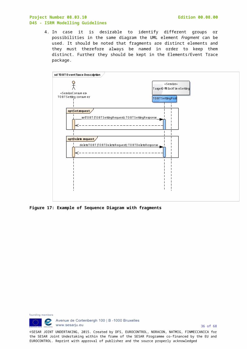
Project Number 08.03.10 Edition 00.08.00D45 - ISRM Modelling Guidelines
Note that Utility services are most of the times defined in the SWIM Technical Infrastructure, i.e. outside the WP8 scope.
Service names shall not end with the suffix 'service' since the element type is given by the stereotype of the model element. The word service may be used in the service name if the service is related to services in one way or another, e.g. a task service named Service Management or an entity service named Service Registry. But that shall not be as a suffix.
B.2 Service Port and Interface naming conventionsService Ports are used to advertise interfaces in runtime. The name of the port is written from the perspective of the provider of the interface.
The Service Interface names should at least differentiate provider interfaces from consumer interfaces. It is also recommended to name the interface so that it is possible to understand to which service the interface belongs by telling what the topic (or sub-topic) is. This is important since the interface may be presented among other interfaces, but without the service context explained.
Service Port and Service Interface names should use the <noun> <role> where <noun> is a topic related to the service and <role> describes the roles in a composition/interaction sequence. The roles can therefore be divided based on the Message Exchange Pattern that is used.
Examples:
FlightPlanCoordinator FlightPlanSubmitter ForecastProvider ForecastConsumer ClearanceRequester ClearanceManager RunwayConfigurationManager PreDepartureSequencer FlightInformationPublisher FlightInformationConsumer AlertListener VideoProvider
Port Examples:
FlightPlanPort ForecastPort ClearancePort
36 of 53©SESAR JOINT UNDERTAKING, 2015. Created by DFS, EUROCONTROL, NORACON, NATMIG, FINMECCANICA for the SESAR Joint Undertaking within the frame of the SESAR Programme co-financed by the EU and EUROCONTROL. Reprint with approval of publisher and the source properly acknowledged
<service-interface-name> ::= <noun> <role>
Project Number 08.03.10 Edition 00.08.00D45 - ISRM Modelling Guidelines
B.2.1 Interface naming in case of request/reply pattern (synchronous and asynchronous)
For entity and utility services in which the interfaces uses the request/reply message exchange pattern (see A.1 and A.2) the default roles of the interfaces are expressed based on the direction of interaction.
Provider. Provided interface where an entity is exposed through the interface. Pull type interaction.
Consumer. Required interface used in asynchronous interaction patterns.
or Receiver. Provided interface that allows for information to be pushed to it. Requester. Required interface used to enable asynchronous replies to a request.
In some cases there is also a need to separate interfaces that are used to provide (read) information from those that are used to manage information (create/update/delete). In this case, the management interface can be named:
Manager. Provided interface in a task/entity/utility service. Indicates need for restricted access.
For task services, the role will reflect the role of the actors in the operational process. A number of roles can be used, such as:
Monitor Surveyor Scheduler Planner Balancer Synchroniser Executor Issuer
B.2.2 Interface naming in case of publish/subscribe patternFor interfaces that uses the publish/subscribe message exchange pattern (see A.3 and A.4), the role of the actor is indicated in the interface name:
Publisher. Provided interface if a pub/sub pattern is used. Subscriber. Required interface if a pub/sub pattern is used.
B.2.3 Interface naming in case of one-way patternIf a one-way message exchange pattern (seeA.5) is to be implemented, then use:
Listener. Provided interface that indicates a passive recipient of messages, i.e. a one-way pattern
No required/consumer interface is implemented in one-way interactions.
B.3 Service Interface Operations naming conventionsService interface operations describes how a client can interact with a service interface, i.e. how it can be invoked. It is important that the client understands what can be done as well as with what.
Service interface operation names should follow the format <verb> <noun> where the <verb> indicates the operation as seen from the invoker perspective and the <noun> indicates the subject of the operation.
37 of 53©SESAR JOINT UNDERTAKING, 2015. Created by DFS, EUROCONTROL, NORACON, NATMIG, FINMECCANICA for the SESAR Joint Undertaking within the frame of the SESAR Programme co-financed by the EU and EUROCONTROL. Reprint with approval of publisher and the source properly acknowledged
<service-interface-operation-name> ::= <verb> <noun>

Project Number 08.03.10 Edition 00.08.00D45 - ISRM Modelling Guidelines
Note 1: The <noun> in an operation name may be omitted if it does not add any additional value. That is if both conditions below are fulfilled:
a) the message that the operation uses as input parameter clearly states what is the subject of the operation. E.g. submit(FlightPlan).
b) there are no other operations in the same interface that uses the same verb.
Note 2: If a <noun> is used in publish/subscribe operation names, the noun should be prefixed by To and From. E.g. subscribeToFlightInformation and unsubscribeFromFlightInformation.
Note 3: lowerCamelCase is used throughout the operation name.
Different verbs should be used depending on the message exchange pattern:
Request/Reply – Synchronous Pull information: get Push information without a callback reply: put
Request/Reply – Asynchronous Ask for something (information/permission/action): request Push information expecting a reply: submit Asynchronous reply: reply
For request/reply patterns there might be other verbs that are applicable in certain operational situations such as: list, search, create, update, clear, activate, deactivate, acknowledge etcetera.
Publish/Subscribe - Push Initiate subscription: subscribe Send notification to a consumer: publish End subscription: unsubscribe
Publish/Subscribe - Pull Initiate subscription: subscribe Get notifications: pull End subscription: unsubscribe
One-way Send notification to a provided service interface: post
38 of 53©SESAR JOINT UNDERTAKING, 2015. Created by DFS, EUROCONTROL, NORACON, NATMIG, FINMECCANICA for the SESAR Joint Undertaking within the frame of the SESAR Programme co-financed by the EU and EUROCONTROL. Reprint with approval of publisher and the source properly acknowledged

Project Number 08.03.10 Edition 00.08.00D45 - ISRM Modelling Guidelines
Examples: getAlerts putAirspaceInformation submitFlightPlan requestClearance clearFlight requestTrajectoryAnalysis replyTrajectoryAnalysis createAccount updateArrivalTime searchArrivalList listServiceProviders subscribeToAirportFlightInformation publishAirportFlightInformation pullAircraftInformation unsubscribeFromAirportFlightInformation postForecast
B.4 Messages/Service Interface Parameters naming conventions
Messages represents the business payload or technical information that is transmitted between a provider and consumer. The correct stereotype in ISRM is Service Interface Parameter. It may travel in both directions and may be parameters passed when invoking a service interface through an operation or be the reply to that invocation.Message names should follow the format <information-product> <message-type> where <information-product> is a noun describing the information being passed between provider and consumer like FlightPlan, Alert etc.<message-type> is a noun describing the type of message, indicating how the recipient is intended to act. E.g. a request where the recipient is expected to reply, a filter that the recipient is expected to take into consideration when replying, a notification where a response is not expected.Common message types in operation invocations are: request, update, query, filter, subscription, notification. Common message types in replies are: fault, exception, acknowledgement, reply, response, list etc. The <message-type> may be omitted if it is only information being passed.
Examples where the first part is the message passed to the interface and the second part is the reply message:
FlightPlanUpdate : void (i.e. no return message) AccountCreationRequest : CreationResponse AlertSelectionCriteria : AlertList FlightArrivalTime : TimeSetAcknowledgement ArrivalSearchQuery : FlightArrivalList ClearanceRequest : ClearanceRequestAcknowledgement ServiceProviderFilter : ServiceProviderList FlightInformationSubscription : FlightInformationSubscriptionResponse FlightInformationNotification : void UnsubscriptionNotification : UnsubscriptionResponse
39 of 53©SESAR JOINT UNDERTAKING, 2015. Created by DFS, EUROCONTROL, NORACON, NATMIG, FINMECCANICA for the SESAR Joint Undertaking within the frame of the SESAR Programme co-financed by the EU and EUROCONTROL. Reprint with approval of publisher and the source properly acknowledged
<service-interface-parameter-name> ::= <information-product> <message-type>

Project Number 08.03.10 Edition 00.08.00D45 - ISRM Modelling Guidelines
Appendix C Example of Service with two portsThis Appendix contains the diagrams of a service model with two ports offering two different Message exchange patterns. It is meant as another example visualising the outcome of the modelling steps described in this document.
class METGriddedForecast Requirements Traceability
«Service»METGriddedForecast
tagsmegaid =
Name: METGriddedForecast Requirements Traceabil i tyAuthor: SVA010 Oliver KruegerVersion: 1.0Created: 14.04.2016 00:00:00Updated: 18.04.2016 00:00:00
«Requirement»Airport MET elements
tagsrefLabel = IER-11.02.01-OSED-LOC1.1002refSource = MET OSED part A (Local OUE) - updaterefURL = reqType = Information exchange requirement
«Requirement»Approach MET elements
tagsrefLabel = IER-11.02.01-OSED-LOC1.1001refSource = MET OSED part A (Local OUE) - updaterefURL = reqType = Information exchange requirement
«Requirement»Network Nominal MET elements
tagsrefLabel = IER-11.02.01-OSED-NET1.1001refSource = MET-OSED part C (Network OUE) - updaterefURL = reqType = Information exchange requirement
«Requirement»TMA & En-route Nominal MET elements
tagsrefLabel = IER-11.02.01-OSED-TER1.1001refSource = MET-OSED part B (Sub-regional OUE) - updaterefURL = reqType = Information exchange requirement
«Requirement»Winds aloft: mean wind speed
tagsrefLabel = IER-06.05.04-OSED-MET2.0011refSource = OFA 05.01.01 Operational Service and Environment DefinitionrefURL = reqType = Information exchange requirement
«Requirement»Winds aloft: mean wind direction
tagsrefLabel = IER-06.05.04-OSED-MET2.0012refSource = OFA 05.01.01 Operational Service and Environment DefinitionrefURL = reqType = Information exchange requirement
«Requirement»Probabilistic w inds aloft forecast, w ind speed
tagsrefLabel = IER-06.05.04-OSED-MET2.0013refSource = OFA 05.01.01 Operational Service and Environment DefinitionrefURL = reqType = Information exchange requirement
«Requirement»Probabilistic w inds aloft forecast, w ind direction
tagsrefLabel = IER-06.05.04-OSED-MET2.0014refSource = OFA 05.01.01 Operational Service and Environment DefinitionrefURL = reqType = Information exchange requirement
«Satisfy» «Satisfy»«Satisfy»«Satisfy» «Satisfy»«Satisfy»«Satisfy»«Satisfy»
Figure 28: METGriddedForecast Service Requirements Traceability Exampleclass METGriddedForecast Interface Definition
«Pub/sub push»METGriddedForecastSubscriber
«Sync req/rep»METGriddedForecastProvider
«Service»METGriddedForecast
«Pub/sub push»METGriddedForecastSubscriber
«Sync req/rep»METGriddedForecastProvider
«interface»METGriddedForecastSubscriber
+ publishMETGriddedForecast(Coverage): void
«interface»METGriddedForecastPublisher
+ subscribeToForecast(CoverageRequest): GetCoverageException+ unsubscribeFromForecast(CoverageRequest): void
«interface»METGriddedForecastProv ider
+ describeCoverage(DescribeCoverageRequest): CoverageDescriptions+ getCapabilities(CapabilityRequest): CoverageCapabilities+ getCoverage(CoverageRequest): Coverage
«ServiceConsumer»METGriddedForecastConsumer
Name: METGriddedForecast Interface DefinitionAuthor: SVA005 Oliver KruegerVersion: 1.0Created: 14.04.2016 00:00:00Updated: 20.04.2016 00:00:00
«require»
«provide»
«provide»
«provide»
«require»
«require»
Figure 29: METGriddedForecast Service Interface Defintion Example
40 of 53©SESAR JOINT UNDERTAKING, 2015. Created by DFS, EUROCONTROL, NORACON, NATMIG, FINMECCANICA for the SESAR Joint Undertaking within the frame of the SESAR Programme co-financed by the EU and EUROCONTROL. Reprint with approval of publisher and the source properly acknowledged

Project Number 08.03.10 Edition 00.08.00D45 - ISRM Modelling Guidelines
class METGriddedForecast Interface Parameter Definition Cov erage
«DataEntity»METGriddedForecastCov erage
+ coverageFunction: CharacterString+ coverageID: Integer+ metadata: CharacterString
«DataEntity»METGriddedForecastDataRecord
+ clearAirTurbulence [0..1]+ cumulonimbusCloudFlightLevelBase [0..1]+ cumulonimbusCloudFlightLevelTop [0..1]+ cumulonimbusCloudHorizontalExtend [0..1]+ humidity [0..1]+ icing [0..1]+ inCloudTurbulence [0..1]+ maxWindDirection [0..1]+ maxWindLevel [0..1]+ maxWindSpeed [0..1]+ qnh [0..1]+ temperature [0..1]+ tropopauseLevel [0..1]+ tropopauseTemperature [0..1]+ windDirection [0..1]+ windSpeed [0..1]
«DataEntity»ForecastForLev el
+ flightLevel
«DataEntity»ForecastForGridPoint
+ gridPointCoordinates
«DataEntity»ForecastAtTimestep
+ validTime
«Message»Coverage
«Message»CoverageRequest
+ coverageID: Integer+ extension: CharacterString+ format: CharacterString+ mediaType: CharacterString [0..1]
«Message»RequestBase
+ request: CharacterString+ service: CharacterString+ version: CharacterString
«DataEntity»DimensionSubset
+ dimension: GM_GriddedSurface
«DataEntity»DimensionSlice
+ slicePoint [0..1]
«DataEntity»DimensionTrim
+ trimHigh [0..1]+ trimLow [0..1]
«Message»GML::Feature
«DataEntity»GML::DomainSet
«DataEntity»SWE Common::
DataRecord
«DataEntity»GML::
GridCoverage
«DataEntity»RangeSet
«DataEntity»GML::RangeSet
«DataEntity»METGriddedForecastDomainSet
+ gridResolution: Real+ issuer+ issueTime
there is a one to one relationship between this entity items
«DataEntity»GetCoverageException
+ getCoverageException: GetCoverageExceptionOptions
Name: METGriddedForecast Interface Parameter Definition CoverageAuthor: SVA010 Oliver KruegerVersion: 1.0Created: 15.04.2016 00:00:00Updated: 18.04.2016 00:00:00
The response to a successful GetCoverage request is a coverage as per [OGC 09-146r2].
«enumeration»GetCoverageExceptionOptions
Attributes+ INVALID_AXIS_LABEL+ INVALID_SUBSETTING+ NO_SUCH_COVERAGE
+domainSet
1
+rangeSet 1
+timeStamp 1
+gridpointInView *
+dimensionSubset 1..
+getCoverageException0..*
+flightLevelInView *
+area 1
+rangeType *
Figure 30: METGriddedForecast Service Interface Parameter Definition Example 1
41 of 53©SESAR JOINT UNDERTAKING, 2015. Created by DFS, EUROCONTROL, NORACON, NATMIG, FINMECCANICA for the SESAR Joint Undertaking within the frame of the SESAR Programme co-financed by the EU and EUROCONTROL. Reprint with approval of publisher and the source properly acknowledged
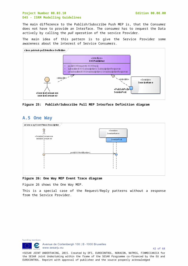
Project Number 08.03.10 Edition 00.08.00D45 - ISRM Modelling Guidelines
class METGriddedForecast Interface Parameter Definition Cov erage Capabilities
«DataEntity»Cov erageSubtypeParent
+ coverageType: CharacterString
«DataEntity»OWS Common::
DatasetSummary
«Message»Cov erageCapabilities
«DataEntity»OWS Common::OWSContents
«Message»CapabilityRequest
+ acceptFormats: CharacterString+ acceptLanguages: CharacterString+ acceptVersions: CharacterString+ request: CharacterString+ sections: Section+ service: CharacterString+ updateSequence: Real
«DataEntity»Cov erageSummary
+ coverageID: Integer+ coverageSubtype: CharacterString+ extensions: CharacterString
«DataEntity»Serv iceMetadata
+ formatSupported: CharacterString
«DataEntity»Contents
not all details provided, for further details see OWS common [OGC09-110r4, OGC06-121r9]
further details see [OGC 06-121r9]
«Message»OWS Common::GetCapabilities
«DataEntity»GetCapabilityException
+ getCapabilitesExceptions: GetCapabili tyExceptionOptions
Name: METGriddedForecast Interface Parameter Definition Coverage Capabil itiesAuthor: SVA010 Oliver KruegerVersion: 1.4Created: 15.04.2016 00:00:00Updated: 15.04.2016 00:00:00
«enumeration»GetCapabilityExceptionOptions
Attributes+ MISSING_PARAMETER_VALUE+ INVALID_PARAMETER_VALUE
«enumeration»Section
Attributes+ SERVICE_PROVIDER+ SERVICE_IDENTIFICATION+ OPERATIONS_METADATA+ CONTENTS+ ALL
+getCapabil ityExecption 0..1
+contents 0..1
+summary 0..*
+serviceMetadata 1
+coveragesubtypeParent 0..*
Figure 31: METGriddedForecast Service Interface Parameter Definition Example 2
42 of 53©SESAR JOINT UNDERTAKING, 2015. Created by DFS, EUROCONTROL, NORACON, NATMIG, FINMECCANICA for the SESAR Joint Undertaking within the frame of the SESAR Programme co-financed by the EU and EUROCONTROL. Reprint with approval of publisher and the source properly acknowledged

Project Number 08.03.10 Edition 00.08.00D45 - ISRM Modelling Guidelines
class METGriddedForecast Interface Parameter Definition Coverage Description
«Message»CoverageDescriptions
«Message»DescribeCoverageRequest
+ coverageID: Integer [1..*]
«Message»RequestBase
+ request: CharacterString+ service: CharacterString+ version: CharacterString
«Message»OWS Common::
OWSRequestBase
«DataEntity»RequestExtension
+ any: CharacterString
«DataEntity»Serv iceParameters
+ coverageSubtype: CharacterString+ coverageSubtypeParent: CharacterString+ extension: CharacterString+ nativeFormat: CharacterString
«DataEntity»CoverageDescriptionExtension
+ any: CharacterString
«DataEntity»GML::Feature
«DataEntity»SWE Common::
DataRecord
«DataEntity»DataRecord
+ rangeType: CharacterString
«DataEntity»GML::DomainSet
«DataEntity»DomainSet
«DataEntity»CoverageDescription
+ coverageFunction: CharacterString+ coverageID: Integer
DataRecord is defined in SWE Common 2.0 [OGC 08-094]
«DataEntity»DescribeCoverageException
+ exception: DescribeCoverageExceptionOptions
Name: METGriddedForecast Interface Parameter Definition Coverage DescriptionAuthor: SVA005 Oliver KruegerVersion: 1.0Created: 15.04.2016 00:00:00Updated: 18.04.2016 00:00:00
«enumeration»DescribeCoverageExceptionOptions
Attributes+ EMPTY_COVERAGE_IDLIST + NO_SUCH_COVERAGE
+extends 0..1
+serviceParameter 1
«SubtypeRelationship»+domainSet 1
+dataRecord 1
+coverageDescription1..*
+describeCapabilityException0..1
+requestExtension 0..1
Figure 32: METGriddedForecast Service Interface Parameter Definition Example 3sd METGriddedForecast Ev ent Trace Description pub/sub
«ServiceConsumer»METGriddedForecastConsumer
«Service»METGriddedForecast
METGriddedForecastSubscriber
loop Data Publication
opt Unsubscription
unsubscribeFromForecast(CoverageRequest)
publishMETGriddedForecast(Coverage)
subscribeToForecast(CoverageRequest): GetCoverageException
Figure 33: METGriddedForecast Service Event trace description 1
43 of 53©SESAR JOINT UNDERTAKING, 2015. Created by DFS, EUROCONTROL, NORACON, NATMIG, FINMECCANICA for the SESAR Joint Undertaking within the frame of the SESAR Programme co-financed by the EU and EUROCONTROL. Reprint with approval of publisher and the source properly acknowledged

Project Number 08.03.10 Edition 00.08.00D45 - ISRM Modelling Guidelines
sd METGriddedForecast Ev ent Trace Description req/reply
Name: METGriddedForecast Event Trace Description req/replyAuthor: SVA005 Oliver KruegerVersion: 1.0Created: 15.04.2016 00:00:00Updated: 19.04.2016 00:00:00
«Service»METGriddedForecast
«ServiceConsumer»METGriddedForecastConsumer MgfProvider
alt
alt
alt
describeCoverage(DescribeCoverageRequest): CoverageDescriptions
getCapabil ities(Capabil ityRequest): CoverageCapabilities
getCoverage(CoverageRequest): Coverage
Figure 34: METGriddedForecast Service Event trace description 2
44 of 53©SESAR JOINT UNDERTAKING, 2015. Created by DFS, EUROCONTROL, NORACON, NATMIG, FINMECCANICA for the SESAR Joint Undertaking within the frame of the SESAR Programme co-financed by the EU and EUROCONTROL. Reprint with approval of publisher and the source properly acknowledged

Project Number 08.03.10 Edition 00.08.00D45 - ISRM Modelling Guidelines
Appendix D Technical modelling supportDuring the creation of the ISRM in SESAR several tools supporting the work of Service Modellers have been developed using Sparx Enterprise Architect for UML modelling. In case this program is used two tools for post-SESAR usage are made available as attachments to the primer document [10].
The following two sections provide introduction to these tools.
D.1 SWIM Logical Service toolboxIn order to create the specific artefacts described in this guideline a special supporting toolbox named SWIM logical service has been added to the Sparx Enterprise Architect tool. The toolbox enables the modeller to more easily create the relevant artefacts. Below, the installation of the toolbox is described. A general introduction to the toolbox support is provided followed by a description of the use of each of the available views and associated toolbox.
D.1.1Toolbox installationIntegration of Model Driven Generation (MDG) Technologies into Enterprise Architect extends the capability of the tool beyond the core modelling capabilities. For the ISRM modelling, several MDG technology components have been developed for integration in EA with the purpose of simplifying the modelling and verification tasks. In this chapter, general aspects of the MDG technology integration and management are presented.
In order to get the MDG components to work, they must be imported to EA. This is done by the Import MDG technology feature, accessible by the menu items:
Tools -> MDG Technology import
or
Project -> Resources
The latter item brings up the project resource window, in which a right-click on MDG Technology will make the import feature available.
Figure 35 The Resources window with Import Technology selectedBoth items will open the window Copy Technology to Application Data.
45 of 53©SESAR JOINT UNDERTAKING, 2015. Created by DFS, EUROCONTROL, NORACON, NATMIG, FINMECCANICA for the SESAR Joint Undertaking within the frame of the SESAR Programme co-financed by the EU and EUROCONTROL. Reprint with approval of publisher and the source properly acknowledged

Project Number 08.03.10 Edition 00.08.00D45 - ISRM Modelling Guidelines
Figure 36 The window used for technology importWhen importing MDG technology, there are two options for making the technology available (by the radio buttons bottom left in the Copy Technology to Application Data window in Figure 36):
Import to Model
This option will import the technology into the current model. Any users of your (local) model will have access to the technology. The technology will be accessible to the current model only. The option allows for integration of separate technologies for different models.
Import to User
This option will import the technology to the current user, making the technology available for the user across models accessed by the user. For this option, the technology files will be stored in the folder %APPDATA%\Sparx Systems\EA\MDGTechnologies on your workstation.
Selection of the file representing the MDG technology to be imported is done by using the browse button upper right in the Copy Technology to Application Data window. When the technology file is selected, information about the technology is presented in the window as shown in Figure 37.
46 of 53©SESAR JOINT UNDERTAKING, 2015. Created by DFS, EUROCONTROL, NORACON, NATMIG, FINMECCANICA for the SESAR Joint Undertaking within the frame of the SESAR Programme co-financed by the EU and EUROCONTROL. Reprint with approval of publisher and the source properly acknowledged

Project Number 08.03.10 Edition 00.08.00D45 - ISRM Modelling Guidelines
Figure 37 Example of a MDG Technology file selected for importIf the MDG Technology already exists, Enterprise Architect displays a prompt for confirmation to overwrite the existing version and import the new one. The typical case for re-import of technologies is when a new version of a technology is released.
Figure 38 Prompt for overwriting existing technologyWhen the import is completed, a restart of Enterprise Architect is needed.
It can be checked if the toolbox is loaded OK by selecting “More tools” from the Toolbox window and verifying that the option “SWIM logical service is available.
47 of 53©SESAR JOINT UNDERTAKING, 2015. Created by DFS, EUROCONTROL, NORACON, NATMIG, FINMECCANICA for the SESAR Joint Undertaking within the frame of the SESAR Programme co-financed by the EU and EUROCONTROL. Reprint with approval of publisher and the source properly acknowledged

Project Number 08.03.10 Edition 00.08.00D45 - ISRM Modelling Guidelines
D.1.2Toolbox usageWhen a modeller wants to create a new diagram (Add diagram), a window describing the different groups of diagrams that the tool supports is presented. By selecting SWIM logical service, the following list appears.
Figure 39: List of possible SWIM logical service diagramsAs can be seen from the icons associated with the different diagrams, most are class diagrams although diagrams of other types are included as well. Irrespective of the choice of diagram, the following steps should be performed when a diagram type has been chosen.
1. Select the diagram type and press ok.
2. Name the diagram so that the choice made is apparent in the name. The reason for this is to make the diagram easy to see in the project browser. The default name is taken from the name of the package the diagram is owned by.
3. Show Property Note in diagram (from menu in EA choose Diagram -> Advanced -> Show Property Note)
When the diagram is opened the type and name of the diagram is shown in the border on top of the writing area and the correct toolbox associated with the diagram is opened.
For each type of diagram there is a corresponding toolbox containing all the elements that need to be shown on that diagram. If you use these elements by dragging and dropping them onto the diagram, they will automatically contain the correct stereotypes and tagged values.
Please keep in mind, that the toolbox is used for creating new elements. If you need to reuse existing elements you may use them from the packages of the service in the project browser.
Here are the four available toolboxes:
48 of 53©SESAR JOINT UNDERTAKING, 2015. Created by DFS, EUROCONTROL, NORACON, NATMIG, FINMECCANICA for the SESAR Joint Undertaking within the frame of the SESAR Programme co-financed by the EU and EUROCONTROL. Reprint with approval of publisher and the source properly acknowledged

Project Number 08.03.10 Edition 00.08.00D45 - ISRM Modelling Guidelines
Figure 40: Interface Definition Toolbox
Figure 41: Interface parameter Definition Toolbox
Figure 42: Event Trace Description Toolbox
Figure 43: Requirements Traceability Toolbox
49 of 53©SESAR JOINT UNDERTAKING, 2015. Created by DFS, EUROCONTROL, NORACON, NATMIG, FINMECCANICA for the SESAR Joint Undertaking within the frame of the SESAR Programme co-financed by the EU and EUROCONTROL. Reprint with approval of publisher and the source properly acknowledged
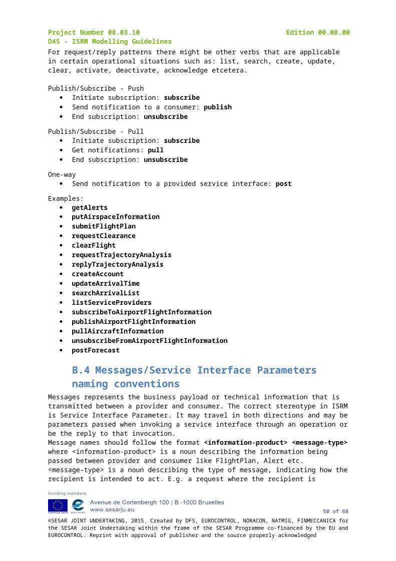
Project Number 08.03.10 Edition 00.08.00D45 - ISRM Modelling Guidelines
D.2 Verification ScriptTo help verify that the ISRM model follows the ISRM Foundation Rulebook [1] a set of verification scripts have been developed for the Sparx EA environment. These scripts are available as attachment to the ISRM Primer document [10] and have to be imported into Enterprise Architect before they can be used. How this is done and the additional actions to make the scripts appear in the Project Browser menu (to execute the verification) is described below.
Please note, that the available scripts do only cover the rules of ISRM Foundation 00.07.00 and not the rules explained in the document! This is for documentation purpose only (describing the approach used in SESAR) and can be used as input for a version 00.08.00 implementation.
Step 1: Get MDG Technology verification scripts into EAImport the isrm_verification_rules.xml and the library_functions.xml files by following the procedure described in the previous chapter.
After a restart of EA, you should have the folders ISRM Verification Rules and Library Functions present in your script window.
Figure 44 EA Scripting window showing the added MDG Technology scripting groupsIf you don’t see your script window enable it by choosing "Scripting" in Tools menu of EA.
Step 2: Create Project Browser menu with verification scripts into EA.1) Access the Scripting window by selecting the menu item Tools -> Scripting. Create a Project
Browser group and name it “ISRM Verification menu” 2) Open the new group's properties and make sure the group type is Project Browser.3) In your new (or existing) Project Browser group, create a new JScript and name it
“AutoVerify”4) By opening the script for edit, replace the generic skeleton for the script with the contents of
the file AutoVerify.js5) Click Save when done.
You should now have the Project Browser menu item as shown in Figure 45 for verifying the model content.
50 of 53©SESAR JOINT UNDERTAKING, 2015. Created by DFS, EUROCONTROL, NORACON, NATMIG, FINMECCANICA for the SESAR Joint Undertaking within the frame of the SESAR Programme co-financed by the EU and EUROCONTROL. Reprint with approval of publisher and the source properly acknowledged

Project Number 08.03.10 Edition 00.08.00D45 - ISRM Modelling Guidelines
Figure 45 Selecting AutoVerify in the Project Browser Scripts menu
Step 3: Running the verification script on packages, elements and diagrams.
1) In the project browser in EA select and right-click on a package, element or diagram. You should now on the top see a menu item Scripts with a sub menu with the AutoVerify entry based on the JScript you imported. Select it.
2) When you select the sub menu item, EA runs the corresponding verification script (which calls the right verification rules scripts) and generates a verification report in a default folder (C:\tmp). The AutoVerify menu item generates a file called nsov-all-verification.csv in the C:\tmp folder. It is a comma-separated file with the verification result for each applicable rule for each node in the ISRM. If you want to change the default output from C:\tmp to something else, you have to manually change the Config JScript in the Library Function folder in the Script window.
3) From the CSV file, you can generate Excel spreadsheet reports according to the procedures described.
Business Process AutoVerify - CSV file upload process
Name: AutoVerify - CSV file upload processAuthor: cabslVersion: 1.0Created: 09.08.2013 00:00:00Updated: 09.08.2013 00:00:00
User selects Autoveri fyfrom the Project Browsermenu
«BusinessProcess»Create CSV files
«BusinessProcess»Create CSV files
Loop over all elements below selectedelement
For each element, loop over al lrelevant rules
Run "check" on theelement for each rule
Create CSV fi le fromdata gathered during
rule checks
CSV file
«BusinessProcess»Create Excel files
«BusinessProcess»Create Excel files
Excel fi les
Done
Upload CSV fi le toweb site, cl ick
"Submit"
Download ZIP and/orExcel fi les
System runs script tocreate Excel fi les,redirects user todownload site
Figure 46: The process of AutoVerify execution and verification report generation
Step 4: Generating verification reports (optional)The EA script AutoVerify described above creates a source CSV file that contains information needed to create the verification reports per service. This CSV file is in turn fed into an external tool that creates an Excel document. It contains one sheet for the automatic rules and one for the manual rules, so that the verification log of the manual rules may be maintained separately and copied and pasted into the final verification report.
In order to run the script, you need Perl. This is included in Cygwin (as well as readily available on Unix-based systems), and may also be downloaded from ActiveState for Windows, at http://www.activestate.com/activeperl/downloads. Assuming you know how to install Perl or already have a working Perl environment, you will need to also install the Perl module Spreadsheet::WriteExcel (using “CPAN”).
51 of 53©SESAR JOINT UNDERTAKING, 2015. Created by DFS, EUROCONTROL, NORACON, NATMIG, FINMECCANICA for the SESAR Joint Undertaking within the frame of the SESAR Programme co-financed by the EU and EUROCONTROL. Reprint with approval of publisher and the source properly acknowledged

Project Number 08.03.10 Edition 00.08.00D45 - ISRM Modelling Guidelines
The perl script is available in the attachment of the ISRM Primer in the verification_reporting directory.
Running the script1) In the command window, type "perl makeexcel.pl –f [location of your CSV
file]” – make sure to use the full or relative path to your CSV file2) The script will proceed to produce one Excel sheet per service contained in the CSV file, if
you ran the AutoVerify script at a level above one particular service
52 of 53©SESAR JOINT UNDERTAKING, 2015. Created by DFS, EUROCONTROL, NORACON, NATMIG, FINMECCANICA for the SESAR Joint Undertaking within the frame of the SESAR Programme co-financed by the EU and EUROCONTROL. Reprint with approval of publisher and the source properly acknowledged

Project Number 08.03.10 Edition 00.08.00D45 - ISRM Modelling Guidelines
-END OF DOCUMENT-
53 of 53©SESAR JOINT UNDERTAKING, 2015. Created by DFS, EUROCONTROL, NORACON, NATMIG, FINMECCANICA for the SESAR Joint Undertaking within the frame of the SESAR Programme co-financed by the EU and EUROCONTROL. Reprint with approval of publisher and the source properly acknowledged