Embed Size (px)
Citation preview
-2
-
Th
e
DÖ
MI
TZ
F
OR
TR
eS
S
–
ST
RU
CT
UR
AL
e
Le
Me
NT
:
SA
ND
ST
ON
e
PO
RT
AL
STRUCTURAL ELEMENT: SANDSTONE PORTAL
ISSUE 2
Fortress Dömitz
Documentation of a Restoration and Repair Project

Fortress
Bus station
Cultural Centre
Marina
Lock
Harbour
Passenger ship wharf
Town rampart
Wasserstraße
Werderstraße
Fritz- Reuter- Straße
Fr.-Franz-Str.
Mühlendeich
Am W
all Elbstr.
Stadtwall
Am Wall
Schu
ster
str.
Tors
tr.
An d
er B
leich
e
An der Festung
Goethe
str.
str.
Marien
nade
Prome-
Straße
Schweriner
195
195
Rathausi
Die dove Elde
Die dove ElbeSlüter-platz
P
P
P
PP
Wal
lstr.
Elbe
STRUCTURAL eLeMeNT: SANDSTONe PORTAL Map of Dömitz/Ground Plan of Dömitz Fortress
Ground plan of fortress complex, right:
1 - Kommandantenhaus (commander’s house)
2 - Remise (coach house)
3 - Zeughaus (armoury)
4 - Freilichtbühne (open-air theatre)
5 - Kanonenrampe (cannon ramp)
6 - Blockhaus (block house)
7 - hauptwache (main guard building)
8 - Arrestantenhaus (prison building)
9 - Wallmeisterhaus (fortification official’s house)
10 - Gateway to outer ward
11 - Casemates
12 - “Cavalier” Bastion
13 - “held” Bastion
14 - “Drache” Bastion
15 - “Greif” Bastion
16 - “Burg” Bastion
17 - Curtain walls
18 - Flank of bastion
19 - Face of bastion
20 - Fortress ditch, counterscarp
21 - Rampart, glacis, covered way, assembly areas for defending
infantry
12
3
46
9
8
7
12
1314
15
16
17
17
18
1920
21
11
5
10Sandstone Portal
Map of Dömitz/Ground Plan of Dömitz Fortress
Table of Contents/Ground Plan of Fortress Complex
1. Preface
2. The Sandstone
3. Anchors, Mortar and Concrete
4. Moisture and Salt Contamination of the Sandstone
5. Damage on the Sandstone Portal
6. Project Planning for the Restoration of the Sandstone Portal
7. Restoration Measures
7.1 Cleaning
7.2 Reduction of the Salt Content
7.3 Dismantling and Re-setting of Severely Displaced Structural elements
7.4 Plumbing Work
7.5 Moisture Barrier between Portal Sandstone elements and Brick Wall
7.6 Masonry Unit Replacement and Stone Grafts
7.7 Strengthening Areas of Granular Disintegration
7.8 Backfilling of Plates/Contour Scaling and Repair of Cracks
7.9 Repair Work with Stone Repair Compounds
7.10 Retouching Repair Work
7.11 Joint Repair
8. The Sandstone Portal Following Completion of Restoration Work
Appendix - Bibliography/List of Parties Involved
Imprint
0
1
2
6
10
12
14
18
20
20
20
22
24
26
27
29
29
30
30
31
32
36
37
Table of Contents/Ground Plan of Fortress Complex
STRUCTURAL eLeMeNT: SANDSTONe PORTAL Table of Contents/Ground Plan of Fortress Complex 1
Situated on the Mecklenburg banks of the elbe River the
Dömitz Fortress is one of the few well preserved flatland
fortresses from the 16th century in northern europe.
Designed in the shape of an equilateral pentagon with
bastions and casemates the fortress is an impressive
example of Renaissance defence architecture.
Johann Albrecht I (1525-1576), duke of Mecklenburg-
Güstrow, recognised the economic and strategic importance
of Dömitz’s location and ordered the building of a fortress
there on the remains of an earlier structure from the 13th
century. This new fortress, the strongest in the land, was
built at great expense between the years of 1557 and 1565
and enabled Mecklenburg to secure its border and control
the collection of customs duties for the elbe River.
Duke Johann Albrecht I maintained relationships with
many european courts and engaged the services of
artists of all genres from the leading cultural centres of
the period. Other significant buildings attributed to this
dynamic territorial lord are the old Schwerin Castle and the
well-preserved Castle of Gadebusch. For the construction
of the Dömitz Fortress he hired the Brescian castle builder
Francesco a Bornau, who was a prominent expert on
defence architecture and had constructed the bastions for
the Schwerin Castle.
Over the past centuries all of the structures built by
Francesco a Bornau inside the fortress, except for the
Kommandantenhaus (commander’s house), have been
replaced by new structures. however, the fortress complex
as a whole has been preserved in its original form to the
present day.
As defensive structures fortresses are designed for
fortification, both in their ground-plan and elevation.
The architecture must ensure effective lines of fire for the
defensive firearms and the absence blind spots.
With their bastions and ramparts fortress structures have
rather austere and forbidding functional architectures
with military character. The only area which was generally
designed with special lavishness and significance was the
fortress entrance. This phenomenon can also be observed
in Dömitz.
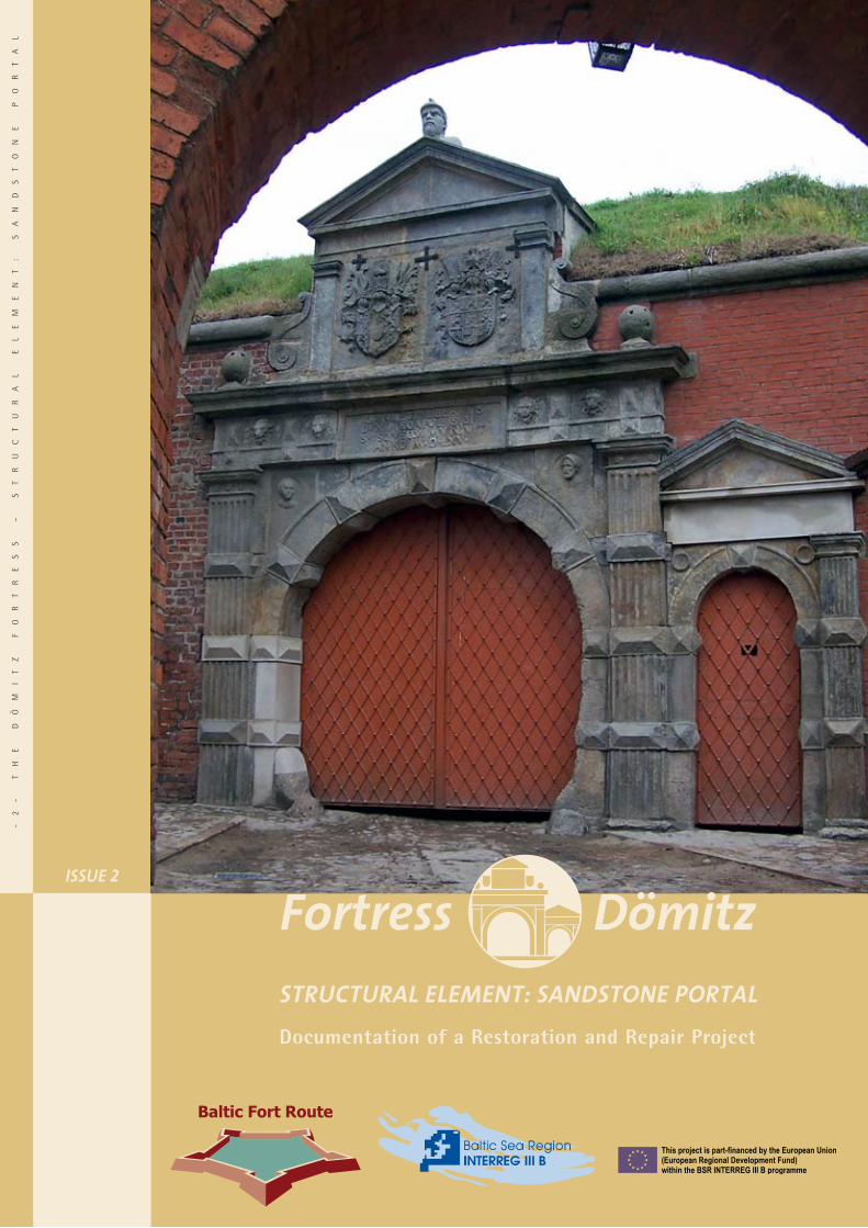
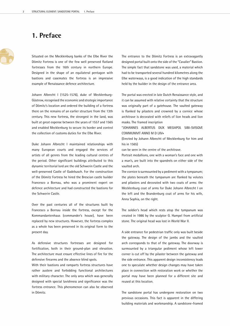
The entrance to the Dömitz Fortress is an extravagantly
designed portal built onto the side of the “Cavalier” Bastion.
The simple fact that sandstone was used, a material which
had to be transported several hundred kilometres along the
elbe waterways, is a good indication of the high standards
held by the builder in the design of the entrance area.
The portal was erected in late Dutch Renaissance style, and
it can be assumed with relative certainty that the structure
was originally part of a gatehouse. The vaulted gateway
is flanked by pilasters and crowned by a cornice whose
architrave is decorated with reliefs of lion heads and lion
masks. The framed inscription
“JOhANNeS ALBeRTUS DUX MeGAPOL SIBI-SVISQVe
COMMUNIVIT ANNO M D LXV»
(erected by Johann Albrecht of Mecklenburg for him and
his in 1565)
can be seen in the centre of the architrave.
Portrait medallions, one with a woman’s face and one with
a man’s, are built into the spandrels on either side of the
vaulted arch.
The cornice is surmounted by a pediment with a tympanum;
the plates beneath the tympanum are flanked by volutes
and pilasters and decorated with two coats of arms: the
Mecklenburg coat of arms for Duke Johann Albrecht I on
the left and the Brandenburg coat of arms for his wife,
Anna Sophia, on the right.
The soldier’s head which rests atop the tympanum was
created in 1986 by the sculptor G. hampel from artificial
stone. The original head was lost in World War II.
A side entrance for pedestrian traffic only was built beside
the gateway. The design of the jambs and the vaulted
arch corresponds to that of the gateway. The doorway is
surmounted by a triangular pediment whose left lower
corner is cut off by the pilaster between the gateway and
the side entrance. This apparent design inconsistency leads
one to speculate whether design changes may have taken
place in connection with restoration work or whether the
portal may have been planned for a different site and
reused at this location.
The sandstone portal has undergone restoration on two
previous occasions. This fact is apparent in the differing
building materials and workmanship. A sandstone-framed
1. Preface
2 STRUCTURAL eLeMeNT: SANDSTONe PORTAL 1. Preface
plaque in the curtain wall beside the fortress entrance
states that the fortress underwent restoration between
1851 and 1865. Further restoration work was performed
in the 1930s.
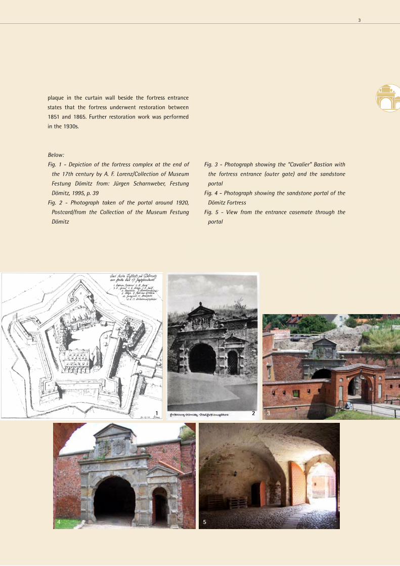
Below:
Fig. 1 - Depiction of the fortress complex at the end of
the 17th century by A. F. Lorenz/Collection of Museum
Festung Dömitz from: Jürgen Scharnweber, Festung
Dömitz, 1995, p. 39
Fig. 2 - Photograph taken of the portal around 1920,
Postcard/from the Collection of the Museum Festung
Dömitz
Fig. 3 - Photograph showing the “Cavalier” Bastion with
the fortress entrance (outer gate) and the sandstone
portal
Fig. 4 - Photograph showing the sandstone portal of the
Dömitz Fortress
Fig. 5 - View from the entrance casemate through the
portal
1 3
4 5
2
3
The restoration of the Dömitz Fortress, which began in
2001, also involved the restoration of the sandstone portal.
This work was performed in the context of the eU project
Interreg III B “BalticFortRoute” in scientific cooperation
with eU partners in Poland, Lithuania and Germany.
extensive preliminary site investigations were performed in
2005 in preparation for the restoration.
As a basis for the structural condition assessment a site
measurement of the portal was performed manually, taking
all deformation into account. The structural condition and
discernible damages were documented photographically
and diagrammed in the planning documents.
A plan for investigating the building stock and analysing
structural materials on the sandstone portal of the Dömitz
Fortress was developed on the basis of visual appraisals
after thorough inspection of the structure. Special
attention was given to indications of high moisture and salt
content in the sandstone elements and the adjacent walls;
these factors are recognised as major causes of weathering
damage in the sandstone elements of the structure.
The restoration technologies developed from the findings
of the investigations were then tested on a sample axis on
the portal. Restoration work on the portal was completed
in the spring of 2007.
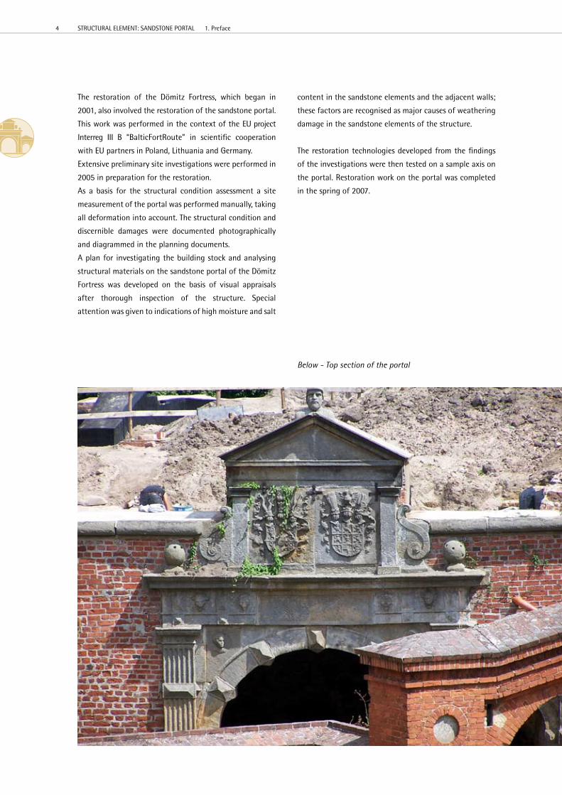
Below - Top section of the portal
4 STRUCTURAL eLeMeNT: SANDSTONe PORTAL 1. Preface
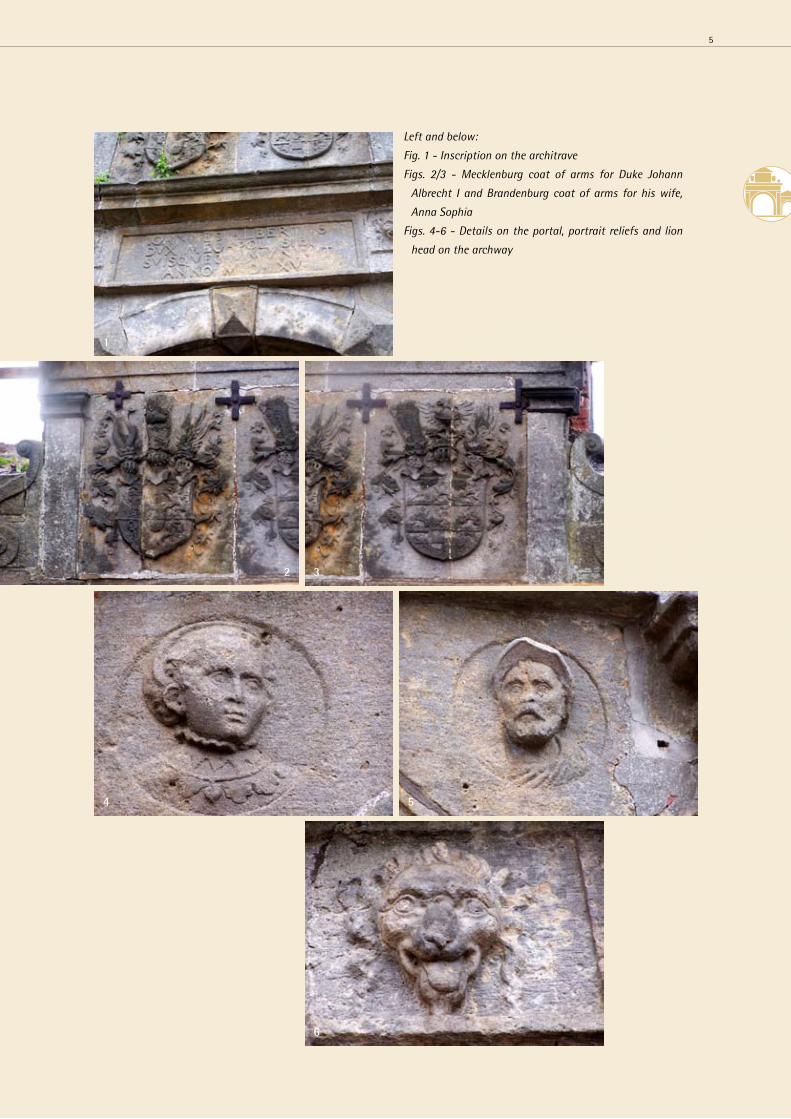
Left and below:
Fig. 1 - Inscription on the architrave
Figs. 2/3 - Mecklenburg coat of arms for Duke Johann
Albrecht I and Brandenburg coat of arms for his wife,
Anna Sophia
Figs. 4-6 - Details on the portal, portrait reliefs and lion
head on the archway
32
1
4 5
6
5

2. The Sandstone
Upon thorough inspection of the object it becomes
apparent that various types of sandstone were used for
the portal, or added during later restoration work. The
sandstone types vary in structure, texture, grain size
and colour, as well as in fossil content and weathering
behaviour.
Based on these macroscopic properties it was possible to
visually identify four different types of sandstone.
Most of the sandstone pieces used in the gateway were
made from either a medium-grain yellow sandstone with
ferritic (iron-bearing) inclusions and banded structures
or a medium-grain grey sandstone with scattered fossil
impressions. Owing to their frequency of occurrence these
types of sandstones are believed to have been the original
building materials.
Several smaller stone segments used for repairs (stone
grafts) and parts of the triangular pediment over the
side entrance are made of a fine-grain grey sandstone
with a lamination indicated by thin, dark grey flasers.
This sandstone appears to have been used for the
restoration work performed between 1851 and 1865. This
assumption is supported by the fact that the frame of
the commemorative plaque in the curtain wall beside the
fortress entrance was also made from this grey, fine-grain
variety of sandstone.
Some other repair segments, along with the raking cornice
of the pediment above the reliefs of the two coats of arms,
are made from a fine-grain yellow sandstone with round
and elongated fossil impressions. The fact that saw marks
are discernible on the crowning tympanum of the portal’s
top section suggests that this sandstone was used for the
restoration work performed in the 1930s. The use of frame
saws for stone-cutting was not common until after 1870.
In order to classify the sandstone, rock samples 1 to 2 cm
in size were taken from the four identified varieties. Thin
sections made from these samples were petrographically
analysed using a polarising microscope. Based on these
analyses the two medium-grain sandstone varieties used
for the original construction were classified as Posta-type
elbe sandstones, and the two fine-grain sandstones used
for later restoration work on the portal were identified as
belonging to the elbe sandstone variety Cotta.
The differentiation between Posta and Cotta sandstones is
an established system of classification for rock taken from
the elbe Sandstone Mountains. These sandstone varieties
have been named for the places where their prototypes
were quarried, or are still quarried to this day: Posta, now
a district of the city of Pirna, and Cotta, a village west of
Pirna.
A large number of quarries, both historical and operational,
are located in the sandstone quarrying region whose
German territory stretches along both sides of the elbe
river from the Czech border to Pirna and is defined
regionally-geographically as the elbe Sandstone Mountains
or Sächsische Schweiz (Saxon Switzerland).
The qualities of rock extracted here as building stone and
cut stone can vary, not only among quarries but also within
the same quarry, where various qualities of rock can be
extracted at different quarry horizons.
The differentiation between Posta and Cotta varieties
of elbe sandstone is oriented more toward their basic
building-stone qualities than their origins.
Posta-type elbe sandstones are characterised by their
high strength. This type of rock is primarily used for load-
bearing structures and in heavily loaded building structures
(plinth trims) as well as for floor and paving slabs, steps
and kerbstones. This type of sandstone also exhibits good
resistance to weathering.
When directly exposed to the influences of weather Posta-
type elbe sandstones will turn black in a relatively short
period of time owing to the process of patination.
Their strength and granularity make them difficult to carve
and cut. Therefore working with this type of sandstone
is a more labour intensive and time consuming process,
associated with high tool wear. It’s suitability for fine
carving work is limited.
Cotta-type elbe sandstones have a lower strength and
are very fine-grained. Therefore this type of rock is
characterised by especially good working properties and
exhibits a good edge strength. As a result it is a preferred
choice of material for fine profiling and sculpting work.
however, its resistance to weathering is moderate to
low. This is especially true when exposed to frequent or
constant moisture penetration (rising damp, splash water).
Some typical weathering effects are flaking and relief-like
back weathering along clay flasers and fossil impressions. It
6 STRUCTURAL eLeMeNT: SANDSTONe PORTAL 2. The Sandstone

seems that several of the stone grafts made from this type
of sandstone began to show signs of damage within just a
few decades and had to be repaired with cement mortar
during later restoration work.
Sandstones from the quarrying regions of Saxony were
used in especially large quantities in the regions east of
the elbe River until the second half of the 19th century
because, prior to the railway age, transport by water via
the elbe and havel rivers represented practically the only
possibility for transporting loads of that size over great
distances.
It is impossible to determine with certainty from which
quarry or quarrying region each of the four sandstone
varieties originated. however it can be said with relative
confidence that at the time when the fortress was built
– during the 2nd half of the 16th century – Posta-type
sandstone was mined primarily, if not exclusively, in the
Posta and Postelwitz quarries and shipped on the elbe. The
medium-grain yellow sandstone with ferritic inclusions
and banded structures corresponds to sandstone from the
Posta quarries, while the medium-grain grey sandstone
with scattered fossil impressions is macroscopically similar
to sandstone from the Postelwitz quarries. Both quarries
are no longer in operation.
The fine-grain grey sandstone with a lamination indicated
by thin, dark grey flasers corresponds macroscopically
to sandstone from the Neuendorf quarries. The fine-
grain yellow sandstone with round and elongated fossil
impressions may have come from the Lohmgrund quarries.
Below:
Fig. 1 - Thin section photomicrograph, medium-grain
sandstone
Fig. 2 - Thin section photomicrograph, fine-grain
sandstone
Fig. 3 - Map from: KUTSCHKE, D.: Steinbrüche und
Steinbrecher in der Sächsischen Schweiz – Series
published by the Stadtmuseum Pirna, Issue 11/2000
1
2 3
7

DÖMITZ FORTReSSSANDSTONe PORTALMATeRIAL MAPPING 2005
Working GroupThomas Bolze, engineerThomas Schuber, restorer
TyPe OF MAPPING
MATeRIAL MAPPING
SITe
DÖMITZ FORTReSS
OBJeCT
SANDSTONe PORTAL
STRUCT. eLeMeNT/AReA
VIeWSCOLOUR SyMBOL
COTTA SANDSTONe, GRey
COTTA SANDSTONe, yeLLOW
POSTA SANDSTONe, yeLLOW, BANDeD
POSTA SANDSTONe, GRey, FOSSIL-CONTAINING
MORTAR ON BRICKWORK
RePAIR MORTAR
VISIBLe IRON eLeMeNTS
DeTeCTeD IRON eLeMeNTS
Above - Material Mapping
8 STRUCTURAL eLeMeNT: SANDSTONe PORTAL 2. The Sandstone

Above and right:
Fig. 1 - Medium-grain yellow Posta sandstone
with ferritic inclusions and bands (original
building material)
Fig. 2 - Medium-grain grey Posta sandstone with
scattered fossil impressions (original building
material)
Fig. 3 - Fine-grain grey Cotta sandstone with a
lamination indicated by thin, dark grey flasers
(used for repair work at the end of the 19th
century)
Fig. 4 - Fine-grain yellow Cotta sandstone with
round and elongated fossil impressions (used
for repair work around 1930)
32
1
4
9
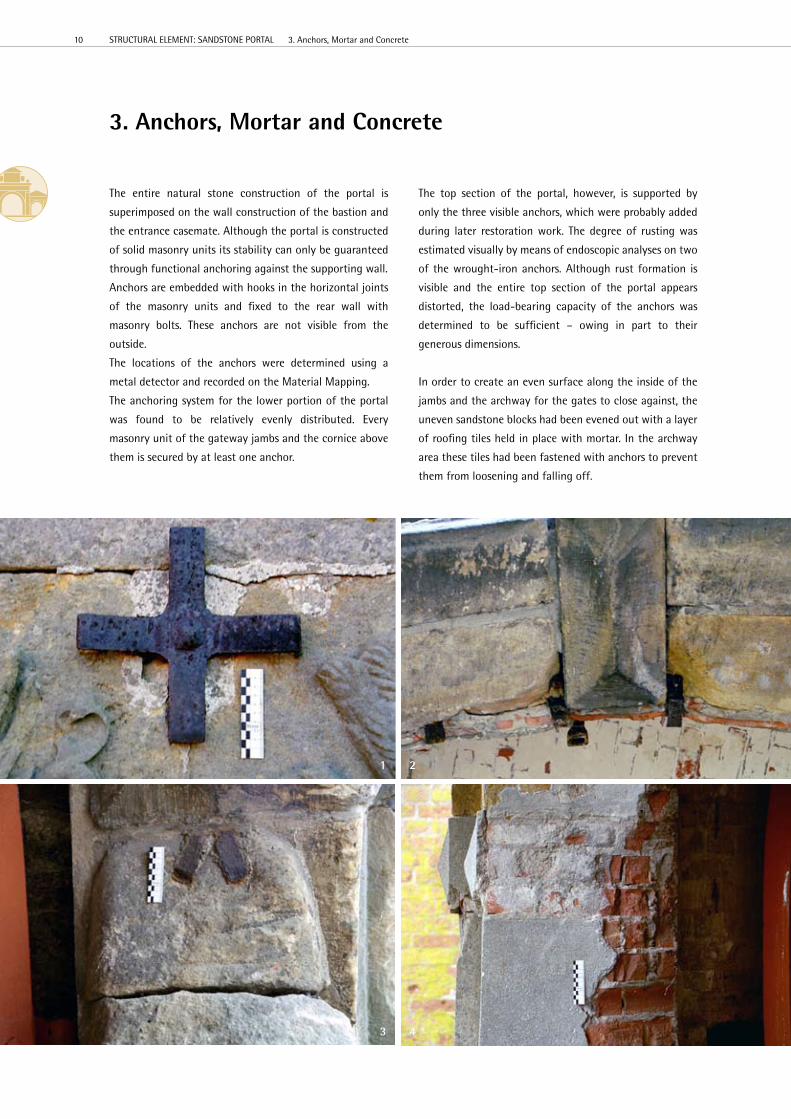
3. Anchors, Mortar and Concrete
The entire natural stone construction of the portal is
superimposed on the wall construction of the bastion and
the entrance casemate. Although the portal is constructed
of solid masonry units its stability can only be guaranteed
through functional anchoring against the supporting wall.
Anchors are embedded with hooks in the horizontal joints
of the masonry units and fixed to the rear wall with
masonry bolts. These anchors are not visible from the
outside.
The locations of the anchors were determined using a
metal detector and recorded on the Material Mapping.
The anchoring system for the lower portion of the portal
was found to be relatively evenly distributed. every
masonry unit of the gateway jambs and the cornice above
them is secured by at least one anchor.
The top section of the portal, however, is supported by
only the three visible anchors, which were probably added
during later restoration work. The degree of rusting was
estimated visually by means of endoscopic analyses on two
of the wrought-iron anchors. Although rust formation is
visible and the entire top section of the portal appears
distorted, the load-bearing capacity of the anchors was
determined to be sufficient – owing in part to their
generous dimensions.
In order to create an even surface along the inside of the
jambs and the archway for the gates to close against, the
uneven sandstone blocks had been evened out with a layer
of roofing tiles held in place with mortar. In the archway
area these tiles had been fastened with anchors to prevent
them from loosening and falling off.
21
43
10 STRUCTURAL eLeMeNT: SANDSTONe PORTAL 3. Anchors, Mortar and Concrete
Below:
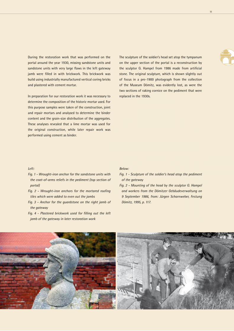
Fig. 1 - Sculpture of the soldier’s head atop the pediment
of the gateway
Fig. 2 - Mounting of the head by the sculptor G. Hampel
and workers from the Dömitzer Gebäudeverwaltung on
9 September 1986, from: Jürgen Scharnweber, Festung
Dömitz, 1995, p. 117.
During the restoration work that was performed on the
portal around the year 1930, missing sandstone units and
sandstone units with very large flaws in the left gateway
jamb were filled in with brickwork. This brickwork was
build using industrially manufactured vertical coring bricks
and plastered with cement mortar.
In preparation for our restoration work it was necessary to
determine the composition of the historic mortar used. For
this purpose samples were taken of the construction, joint
and repair mortars and analysed to determine the binder
content and the grain-size distribution of the aggregates.
These analyses revealed that a lime mortar was used for
the original construction, while later repair work was
performed using cement as binder.
Left:
Fig. 1 - Wrought-iron anchor for the sandstone units with
the coat-of-arms reliefs in the pediment (top section of
portal)
Fig. 2 - Wrought-iron anchors for the mortared roofing
tiles which were added to even out the jambs
Fig. 3 - Anchor for the guardstone on the right jamb of
the gateway
Fig. 4 - Plastered brickwork used for filling out the left
jamb of the gateway in later restoration work
The sculpture of the soldier’s head set atop the tympanum
on the upper section of the portal is a reconstruction by
the sculptor G. hampel from 1986 made from artificial
stone. The original sculpture, which is shown slightly out
of focus in a pre-1900 photograph from the collection
of the Museum Dömitz, was evidently lost, as were the
two sections of raking cornice on the pediment that were
replaced in the 1930s.
21
11
4. Moisture and Salt Content of the Sandstones
The sandstones of the portal showed clear signs of surface
weathering.
In order to identify the causes for these chemical-physical
weathering processes, along with the factors promoting
them, the moisture and salt content of the sandstone
elements and the adjacent brickwork was investigated.
The moisture analysis was carried out using the microwave
moisture measurement system MOIST from the company
hf sensor.
The microwave method falls under the category of
dielectric moisture measurement. Dielectric measurement
processes are based on the unique dielectric properties
of water. Water is a polar molecule, meaning that the
centres of charge do not coincide within the molecule.
Therefore the water molecule orients itself in a preferential
direction within an applied field; it is polarisable. If an
electromagnetic alternating field is applied the molecules
begin to rotate with the frequency of the field (orientation
polarisation). This effect is described macroscopically by
the physical quantity Dielectric Constant (k).
The brickwork areas were examined using the surface
sensor, which is able to measure moisture distribution
within approx. 3 cm of the surface, as well as the volume
sensor, which has a measuring depth of approx. 30 cm.
Sandstone elements were only examined with the surface
sensor because most of these blocks have thicknesses of
less than 30 cm.
Using the corresponding analysis program the moisture
content can be determined in mass% and the moisture
distribution data represented graphically.
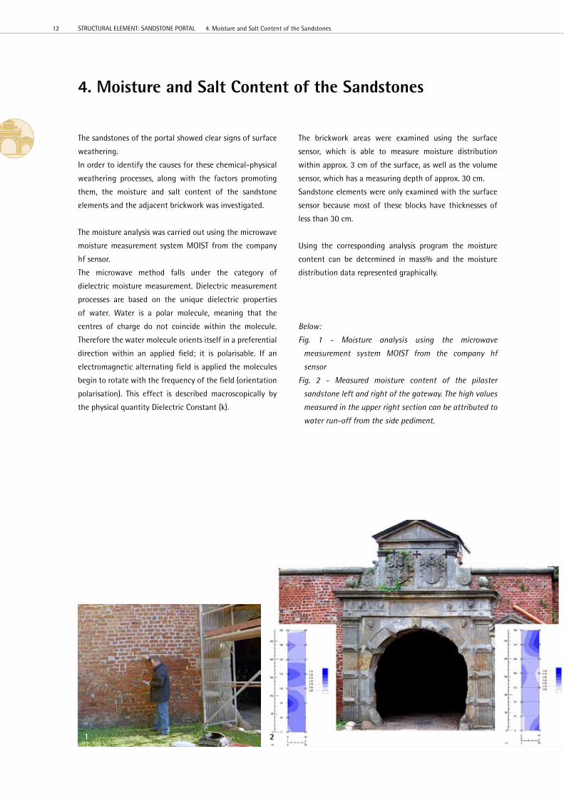
Below:
Fig. 1 - Moisture analysis using the microwave
measurement system MOIST from the company hf
sensor
Fig. 2 - Measured moisture content of the pilaster
sandstone left and right of the gateway. The high values
measured in the upper right section can be attributed to
water run-off from the side pediment.
1 2
12 STRUCTURAL eLeMeNT: SANDSTONe PORTAL 4. Moisture and Salt Content of the Sandstones

high salt content Moderate salt content Low salt content high gypsum content
Measurements taken on the brickwork revealed high
moisture content in all sections of the wall up to a height
of approx. 1.40 m; the moisture content for some areas
was found to be at near saturation. This moisture is most
certainly the result of rising damp from the ground.
Measurements taken on the sandstone pilasters showed a
similar condition. here, however, we must assume that the
moisture is migrating from the adjoining brickwork beside
and behind the sandstone.
Measurements taken on the sandstone elements above
the archway and main cornice revealed increasing
moisture values from top to bottom. The reason for this
phenomenon was the penetration of rainwater into the
structural elements from above.
In summary it was found that the moisture content of the
sandstone that makes up the portal is high, and in some
areas extremely high. The reasons for the penetration of
moisture, along with rising damp in the brickwork, were
the uncovered plates of the cornices that form the upper
surfaces of the structure, open joints and seepage water
from the bastion. A direct relationship was observed
between moisture content and sandstone damage.
In order to investigate the content of structurally damaging
salts in the sandstone and the adjacent brickwork various
types of samples were taken. One non-destructive method
for sample collection is the scratch test; for this test,
samples are taken of deposits or efflorescence from the
surface only. Scratch tests, however, are only useful in
determining the chemical composition of the salts, not the
quantitative salt content of the structural material.
In order to perform a complete salt analysis the collection
of drill dust samples was necessary. For this method a 6-
8mm carbide bit is drilled into the structural material, and
the drill dust collected.
The salt analyses revealed that the salt content of the portal
sandstone varies greatly. The area above the archway, for
example, was found to have a salt content near zero, while
a high content of structurally damaging salts was found
in the jambs and pilasters owing to rising damp from the
adjacent brickwork.
Below:
Fig. 1 - Measurements taken in the coat-of-arms area of
the top portal section
Fig. 2 - Mapping of the collected samples and their salt
content
21
13

5. Damage on the Sandstone Portal
Along with the damage closely associated with the
moisture and salt content of the sandstone numerous other
types of damage were observed during the preliminary
investigation. All observed damage was documented in the
form of a Damage Mapping.
Below - Damage Mapping
14 STRUCTURAL eLeMeNT: SANDSTONe PORTAL 5. Damage on the Sandstone Portal
DÖMITZ FORTReSSSANDSTONe PORTALCONDITION ASSeSSMeNT 2005
Working GroupThomas Bolze, engineerThomas Schuber, restorer
TyPe OF MAPPING
DAMAGe MAPPING
SITe
DÖMITZ FORTReSS
OBJeCT
SANDSTONe PORTAL
STRUCT. eLeMeNT/AReA
VIeWS
COLOUR SyMBOL
BReAK OUT / FLAWS
CRACKS
GRANULAR DISINTeGRATION
CONTOUR SCALING
CRUSTS
RePAIR MORTAR
MORTAR ON BRICKWORK
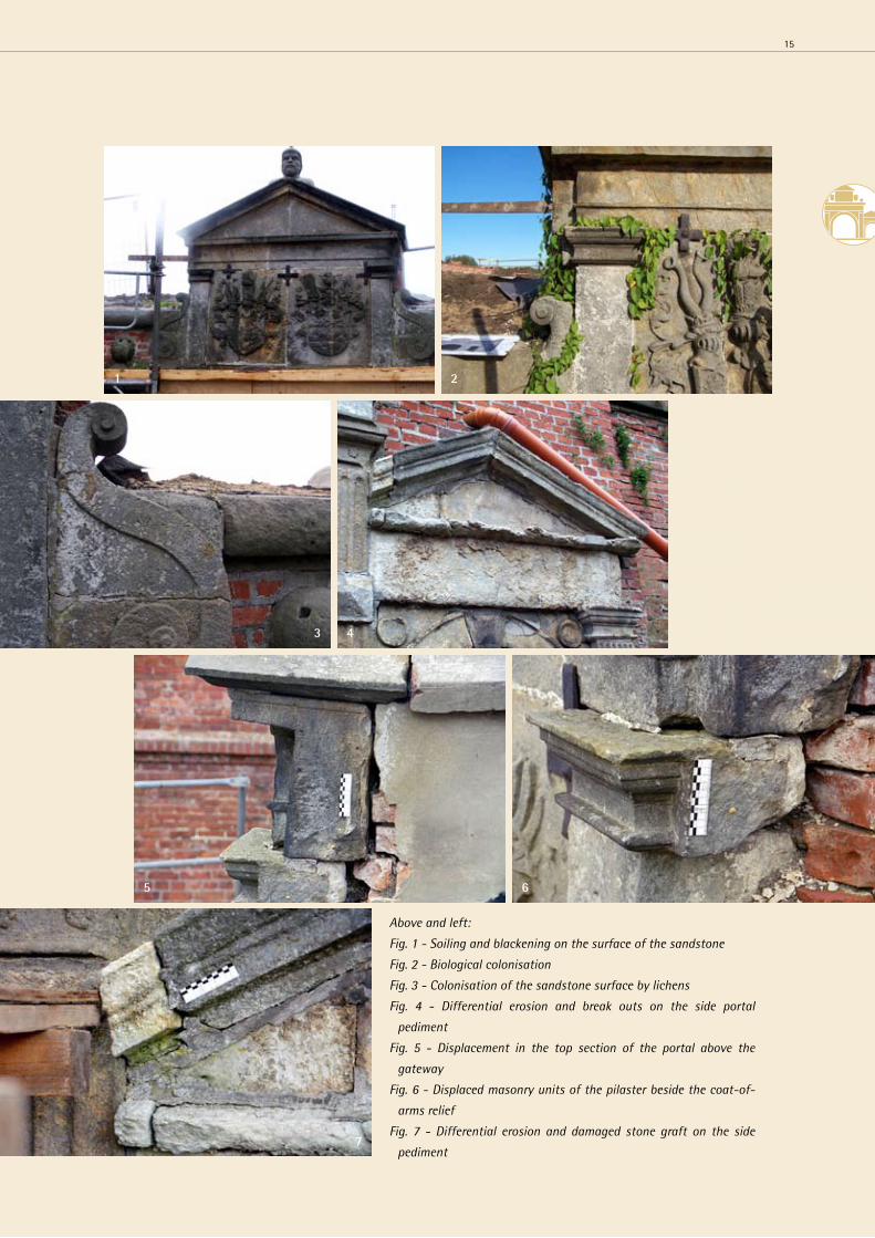
Above and left:
Fig. 1 - Soiling and blackening on the surface of the sandstone
Fig. 2 - Biological colonisation
Fig. 3 - Colonisation of the sandstone surface by lichens
Fig. 4 - Differential erosion and break outs on the side portal
pediment
Fig. 5 - Displacement in the top section of the portal above the
gateway
Fig. 6 - Displaced masonry units of the pilaster beside the coat-of-
arms relief
Fig. 7 - Differential erosion and damaged stone graft on the side
pediment
1 2
43
5
7
6
15

Above and left:
Fig. 1 - Break outs on the right jamb of the
gateway caused by vehicles
Fig. 2 - Broken off section of repair material
Fig. 3 - Relief structure from differential erosion
on the pediment
Fig. 4 - Flaking surface on the tympanum
Fig. 5 - Granular disintegration on the surface of
a pilaster section
Fig. 6 - Crack formation
1 2
43
5
6
16 STRUCTURAL eLeMeNT: SANDSTONe PORTAL 5. Damage on the Sandstone Portal

Above and left:
Fig. 1 - Crust formation on the lower surface of
the arch
Fig. 2 - Soiling from splashed paint on the jamb,
high-water mark
Fig. 3 - Widened joint with chipped flanks on the
cornice
Fig. 4 - Cracks in mortar repair work
Fig. 5 - Damaged repair work on the left jamb of
the gateway
32
1
4
5
17
After the completion of the structural survey and
structural condition assessment, recommendations were
developed for the actual restoration of the portal. The
recommended measures were examined with regard to
technical and aesthetic suitability then assessed and
reviewed based on criteria applied to the preservation of
historic monuments.
First, several sample areas were identified on the pilaster
which separates the gateway from the side entrance and
on the right jamb of the side entrance. All types of damage
observed on the portal were represented among the sample
areas, allowing a “trial restoration” to be planned.
The work was to be performed in the winter months of
2005/06; therefore a compact climatised structure was
built around the applicable areas of the portal.
6. Project Planning for the Restoration of the Sandstone Portal
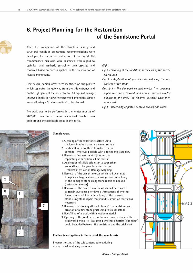
Right:
Fig. 1 - Cleaning of the sandstone surface using the micro-
jet method
Fig. 2 - Application of poultices for reducing the salt
content of the stone
Figs. 3-5 - The damaged cement mortar from previous
repair work was removed, and new restoration mortar
applied to the area. The repaired surfaces were then
retouched.
Fig. 6 - Backfilling of plates, contour scaling and cracks
Above - Sample Areas
Sample Areas
1. Cleaning of the sandstone surface using a micro-abrasive masonry cleaning system2. Treatment with poultices to reduce the salt content - wherever possible with directed moisture flow3. Removal of cement mortar jointing and repointing with hydraulic lime mortar4. Application of silicic acid ester to strengthen areas affected by granular disintegration - marked in yellow on Damage Mapping5. Removal of the cement mortar which had been used to replace a large section of missing stone; rebuilding of the damaged stone using stone repair compound (restoration mortar)6. Removal of the cement mortar which had been used to repair several smaller flaws > Assessment of whether flaws require refilling > Rebuilding of the damaged stone using stone repair compound (restoration mortar) as necessary 7. Removal of a stone graft made from Cotta sandstone and creation of a new stone graft using Posta sandstone8. Backfilling of a crack with injection material9. Opening of the joint between the sandstone portal and the brickwork behind it > evaluating whether a barrier (lead sheet) could be added between the sandstone and the brickwork
Further investigations in the area of the sample axis
Frequent testing of the salt content before, duringand after salt-reducing measures
18 STRUCTURAL eLeMeNT: SANDSTONe PORTAL 6. Project Planning for the Restoration of the Sandstone Portal

Fig. 7 - Pointing work
Figs. 8-10 - Following the removal of an older, clearly
damaged section of repair mortar in the jamb the
damaged surface of the stone was prepared using
stonemasonry techniques and filled in with a structural
element crafted from Posta sandstone (stone graft).
21 3
4 5
76
9 10
8
19

The restoration measures which were determined based
on the preliminary investigations and structural condition
assessment were successfully tested on the sample areas. It
was then possible to begin restoration work on the portal
in the summer of 2006.
7.1 Cleaning
All visible surfaces of the sandstone blocks which make up
the portal were cleaned using a restorative micro-abrasive
masonry cleaning system. This system uses compressed air
and a nozzle to spray a dry mineral or organic abrasive
against the surface to be cleaned. The friction produced
by the powder against the surface breaks down surface
impurities, leaving the surface clean. The abrasive, pressure,
nozzle diameter and distance to the surface can be varied
to achieve the desired cleaning intensity.
The objective of these cleaning measures was to remove
or reduce the dust deposits, blackening and gypsum crusts
on the sandstone surface in order to improve the diffusion
behaviour and prepare for preservation measures.
Areas of heavier soiling which could not be cleaned away
with the micro-abrasive system (e.g. paint) were removed
using a scalpel.
Below:
Fig. 1 - Micro-abrasive cleaning
Fig. 2 - Pilaster following cleaning work, with reference
areas showing the condition of the surface prior to
cleaning
7.2 Reduction of the Salt Content
The sandstone blocks which form the pilasters and the
jambs on either side of the gateway and side entrance
were found to have high salt contents in some parts. The
identified salts were a mixture of various nitrates and
chlorides. Furthermore, along with gypsum, a relatively
high sodium sulphate content was detected in some areas.
This type of salt known to be especially damaging to
building materials.
A salt-reduction treatment was carried out using a
desalination poultice. This treatment is based on the
transportation of salts from the rock into the poultices by
means of a directed flow of moisture. For this purpose the
treated stone is irrigated through integrated tubing from a
water supply tank.
The desalination poultice used for this project contained
perlite, sand, kaolinite and other components.
First, all cement mortar which had been used for earlier
repairs on the portal was removed. Then holes (Ø 6 mm and
depth 200 mm) were drilled in 30cm intervals (wherever
possible, in joints or in flaws which would be filled in later
with repair mortar). Through these holes the stones were
irrigated with special stainless steel cannulas through a
system of silicone tubing.
7. Restoration Measures
21
20 STRUCTURAL eLeMeNT: SANDSTONe PORTAL 7. Restoration Measures
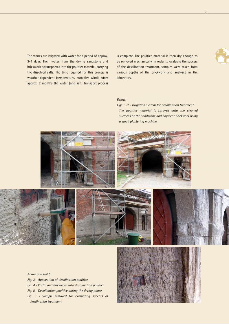
The stones are irrigated with water for a period of approx.
3-4 days. Then water from the drying sandstone and
brickwork is transported into the poultice material, carrying
the dissolved salts. The time required for this process is
weather-dependent (temperature, humidity, wind). After
approx. 2 months the water (and salt) transport process
Below:
Figs. 1-2 - Irrigation system for desalination treatment
The poultice material is sprayed onto the cleaned
surfaces of the sandstone and adjacent brickwork using
a small plastering machine.
Above and right:
Fig. 3 - Application of desalination poultice
Fig. 4 - Portal and brickwork with desalination poultice
Fig. 5 - Desalination poultice during the drying phase
Fig. 6 - Sample removed for evaluating success of
desalination treatment
is complete. The poultice material is then dry enough to
be removed mechanically. In order to evaluate the success
of the desalination treatment, samples were taken from
various depths of the brickwork and analysed in the
laboratory.
43 5
6
1 2
21
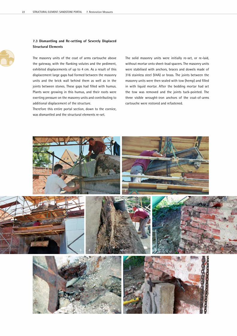
7.3 Dismantling and Re-setting of Severely Displaced
Structural Elements
The masonry units of the coat of arms cartouche above
the gateway, with the flanking volutes and the pediment,
exhibited displacements of up to 4 cm. As a result of this
displacement large gaps had formed between the masonry
units and the brick wall behind them as well as in the
joints between stones. These gaps had filled with humus.
Plants were growing in this humus, and their roots were
exerting pressure on the masonry units and contributing to
additional displacement of the structure.
Therefore this entire portal section, down to the cornice,
was dismantled and the structural elements re-set.
The solid masonry units were initially re-set, or re-laid,
without mortar onto sheet-lead spacers. The masonry units
were stabilised with anchors, braces and dowels made of
316 stainless steel (V4A) or brass. The joints between the
masonry units were then sealed with tow (hemp) and filled
in with liquid mortar. After the bedding mortar had set
the tow was removed and the joints tuck-pointed. The
three visible wrought-iron anchors of the coat-of-arms
cartouche were restored and refastened.
1 2
43 5
6 7
22 STRUCTURAL eLeMeNT: SANDSTONe PORTAL 7. Restoration Measures
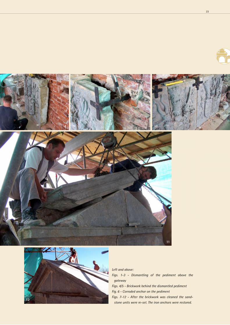
Left and above:
Figs. 1-3 - Dismantling of the pediment above the
gateway
Figs. 4/5 - Brickwork behind the dismantled pediment
Fig. 6 - Corroded anchor on the pediment
Figs. 7-12 - After the brickwork was cleaned the sand-
stone units were re-set. The iron anchors were restored.
98 10
11
12
23
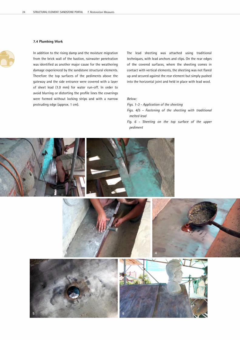
7.4 Plumbing Work
In addition to the rising damp and the moisture migration
from the brick wall of the bastion, rainwater penetration
was identified as another major cause for the weathering
damage experienced by the sandstone structural elements.
Therefore the top surfaces of the pediments above the
gateway and the side entrance were covered with a layer
of sheet lead (1.0 mm) for water run-off. In order to
avoid blurring or distorting the profile lines the coverings
were formed without locking strips and with a narrow
protruding edge (approx. 1 cm).
The lead sheeting was attached using traditional
techniques, with lead anchors and clips. On the rear edges
of the covered surfaces, where the sheeting comes in
contact with vertical elements, the sheeting was not flared
up and secured against the rear element but simply pushed
into the horizontal joint and held in place with lead wool.
Below:
Figs. 1-3 - Application of the sheeting
Figs. 4/5 - Fastening of the sheeting with traditional
melted lead
Fig. 6 - Sheeting on the top surface of the upper
pediment
21
3 4
5 6
24 STRUCTURAL eLeMeNT: SANDSTONe PORTAL 7. Restoration Measures

Left and below:
Figs. 1/2 - Sealing of joints with lead wool
Fig. 3 - Pediment with sheeting
Fig. 4 - Pediment above the gateway after re-setting
2
1
3
4
25

7.5 Moisture Barrier between Portal Sandstone
Elements and Brick Wall
In order to permanently stop the migration of moisture
and associated salts from the brickwork the sandstone
units that form the pilasters and the jambs of the gateway
and side entrance were sealed off from the rear brickwork
of the bastion and the entrance casemate.
For this purpose slots were chiselled in sections into the
brickwork behind the sandstone units. A rolled lead sheet
was pushed into the slot, covering the entire rear surface
of the sandstone unit. The slots in the brickwork were then
filled in with bricks and plastered.
Below:
Fig. 1 - Sheet for sealing off the sandstone from the
brickwork
Figs. 2/3 - Dismantling of the displaced pediment over the
side entrance
Fig. 4 - The joints of the archway over the side entrance
were sealed with lead in order to achieve a certain level
of tension and stability.
Figs. 5/6+6a - The masonry units were initially re-set, or
re-laid, without mortar onto sheet-lead spacers. The
joints were then sealed with tow (hemp) and filled in
with liquid mortar.
1 2
3 4
65 6a
26 STRUCTURAL eLeMeNT: SANDSTONe PORTAL 7. Restoration Measures

Above:
Figs. 1/2 - Left jamb following the removal of old stone grafts
and cement-mortar repairs
Fig. 3 - Replacement of the upper section of the guardstone
inside the left jamb
Fig. 4 - Left jamb with newly fabricated masonry units
7.6 Masonry Unit Replacement and Stone Grafts
Masonry unit replacement implies the complete removal
of a masonry element and replacement with a newly
fabricated element. This measure was required in the
left pilaster of the sandstone portal, on the jamb of the
gateway, and on the frieze and lower cornice of the
pediment above the side entrance.
Traditional stonemasonry techniques were used to craft
the new masonry units from Posta-type sandstone and set
them in the portal.
The pediment above the side entrance, which was severely
displaced and shifted toward the front, had to be completely
dismantled down to the vaulted arch for the replacement
of damaged masonry units. The usable masonry units were
then re-set together with newly fabricated units.
1 2
3
4
27

The new stone grafts were made from Posta-type sandstone
from the Mühlleite quarry; the macroscopic and physico-
mechanical properties of this sandstone were found to be
very similar to the sandstone of the original structure.
The stone grafts were dimensioned using traditional
stonemasonry techniques, i.e. without sawn surfaces or
profiles. The surfaces of the grafts were prepared using
techniques similar to those used for the existing masonry
units; for most of this work hand-forged tools were used.
The stone grafts were fastened with dowels made of
316 stainless steel (V4A) and aligned using lead spacers,
depending on the specific requirements of the repair.
The joints were grouted and tuck-pointed with a hydraulic
lime mortar.
Stone grafts are used for repair work in partially damaged
natural stone units; for such repairs a stonemason chisels
out the damaged area (stone-graft placement site) for the
fitting of a replacement piece (stone graft).
During earlier restoration work on the portal large flaws
were repaired with stone grafts or filled in with plastered
brickwork. Cotta-type elbe sandstone was used for the
stone grafts. The properties, in particular the weathering
properties, for this type of sandstone differ greatly from
those of the sandstones used for the original structure
(Posta-type elbe sandstones). All of the stone grafts made
from Cotta sandstone were already showing signs of
significant weathering damage.
These stone grafts, as well as the plastered brickwork, were
removed and replaced with newly fabricated stone grafts.
Below:
Figs. 1-4 - Stone grafts on pilaster and in the architrave
area
1 2
3 4
28 STRUCTURAL eLeMeNT: SANDSTONe PORTAL 7. Restoration Measures

7.7 Strengthening Areas of Granular Disintegration
A silicic acid ester was used for consolidating structurally
deteriorated areas near the surface of the sandstone
unit which were disintegrating, flaking or eroding into
cavernous pit. For this purpose the affected areas were
flooded using syringes and cannulas. Areas adjacent to
mortar repairs were also strengthened by pre-moistening.
Silicic acid esters (SAe) are liquids produced through
the reaction of silicic acids with alcohol. During the
strengthening process various reactions occur, ending
with the reaction of SAe with water to yield alcohol and
an amorphous silica gel. The newly formed alcohol, along
with any solvent residues, evaporates, leaving behind the
silica gel. The silica gel does not form a film that covers all
of the pore walls; instead it primarily collects in the spaces
between the grains of the rock. Consequently strength
is added to the structure exactly where it is needed.
A relatively small amount of material is sufficient for
achieving significant strengthening of the material.
Various techniques can be used for the application of silicic
acid esters to the surface of the stone. For both the sample
areas and later restoration work the material was applied
using injection syringes; with this method the consolidator
can be very well-directed and precisely dosed. Generally the
stone is saturated in repeated applications wet-in-wet.
7.8 Backfilling of Plates/Contour Scaling and Repair
of Cracks
An injection mortar composed of silicic acid ester, fillers
and glass beads in a fixed ratio was used for filing in
smaller cracks and backfilling hollow layers and large
scales. The injection mortar was mixed well to disperse
individual components and then injected into the cracks
and hollow layers with injection syringes; these areas had
been pre-moistened with silicic acid ester prior to the
application of the injection material. The silicic acid ester is
used here as a binder which functions in the same way as in
the strengthening treatments: through the secretion of an
amorphous silica gel that cements the aggregates together
and to the flanks of the cracks.
Below:
Fig. 1 - Strengthening areas of granular disintegration on
the dismantled masonry units of the coat-of-arms plate
Fig. 2 - Application of injection material using a syringe
Fig. 3 - Crack following the application of injection
material. The discolouration around the crack from the
preliminary moistening with silicic acid ester recedes
after the ester has fully cured and dried.
1
2
3
29

32 4 5
1
6 7
7.9 Repair Work with Stone Repair Compounds
(Restoration Mortars)
The cement mortar which had been used for stone
replacement in earlier restoration work was removed.
Mortar which had not already begun to loosen had to be
chipped away mechanically. This work was performed with
great care, ensuring that as much of the adjacent stone
substance as possible was retained.
A stone repair compound with a silicic acid ester binder
was used for closing small to medium-sized flaws and
areas of back-weathering as well as filling in spaces around
plates of detached stone and contour scaling. In order to
improve the adhesion of the repair mortar the surface of
stone to be repaired was pre-moistened with SAe, and a
bonding agent was applied.
The patches were made flush with the surface. Shallow
flaws only required a single application of material to
attain the required level. For larger repairs, however, the
material was applied in layers. In this case the surface of
the lower layer was roughened before the next layer was
applied in order to avoid leaving solid and smooth surfaces
which could inhibit proper bonding.
7.10 Retouching Repair Work
The stone repair compounds used for the repair work were
matched to the colour of the surrounding rock. For this
purpose pigments were added to the dry mortar. Because
the sandstone colour and degree of patination can vary
greatly the repair compound was later retouched to
harmonise with the adjacent rock.
This process involved the application of colour to the
patches using dry silicate chalks; various shades of chalk
were mixed on the surface of the patch to match it to the
surrounding area. This retouching work was then fixed
using a silicic acid ester.
Above and right:
Figs. 1-5 - Patching flaws with
stone repair mortar
Figs. 6/7 - Retouching repair
work
30 STRUCTURAL eLeMeNT: SANDSTONe PORTAL 7. Restoration Measures
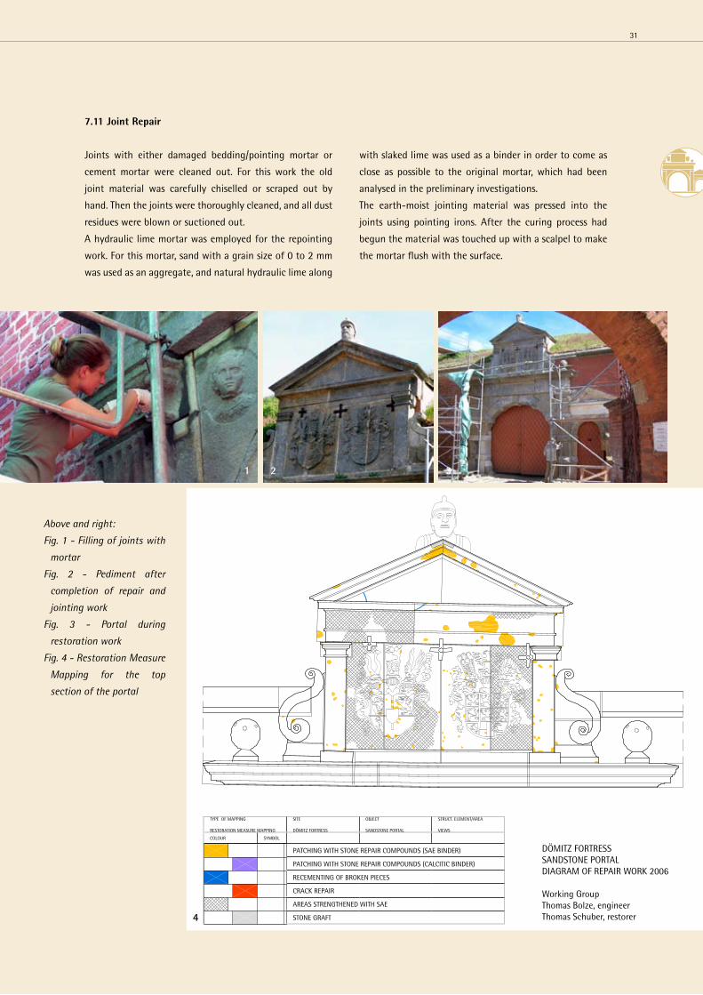
7.11 Joint Repair
Joints with either damaged bedding/pointing mortar or
cement mortar were cleaned out. For this work the old
joint material was carefully chiselled or scraped out by
hand. Then the joints were thoroughly cleaned, and all dust
residues were blown or suctioned out.
A hydraulic lime mortar was employed for the repointing
work. For this mortar, sand with a grain size of 0 to 2 mm
was used as an aggregate, and natural hydraulic lime along
with slaked lime was used as a binder in order to come as
close as possible to the original mortar, which had been
analysed in the preliminary investigations.
The earth-moist jointing material was pressed into the
joints using pointing irons. After the curing process had
begun the material was touched up with a scalpel to make
the mortar flush with the surface.
Above and right:
Fig. 1 - Filling of joints with
mortar
Fig. 2 - Pediment after
completion of repair and
jointing work
Fig. 3 - Portal during
restoration work
Fig. 4 - Restoration Measure
Mapping for the top
section of the portal
DÖMITZ FORTReSSSANDSTONe PORTALDIAGRAM OF RePAIR WORK 2006
Working GroupThomas Bolze, engineerThomas Schuber, restorer
TyPe OF MAPPING
ReSTORATION MeASURe MAPPING
SITe
DÖMITZ FORTReSS
OBJeCT
SANDSTONe PORTAL
STRUCT. eLeMeNT/AReA
VIeWS
COLOUR SyMBOL
PATChING WITh STONe RePAIR COMPOUNDS (SAe BINDeR)
PATChING WITh STONe RePAIR COMPOUNDS (CALCITIC BINDeR)
ReCeMeNTING OF BROKeN PIeCeS
CRACK RePAIR
AReAS STReNGTheNeD WITh SAe
STONe GRAFT
21 3
4
31
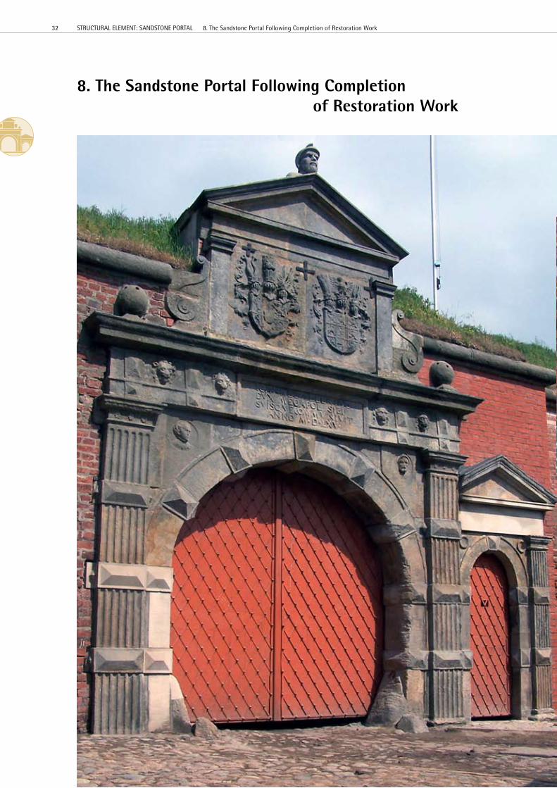
8. The Sandstone Portal Following Completion of Restoration Work
32 STRUCTURAL eLeMeNT: SANDSTONe PORTAL 8. The Sandstone Portal Following Completion of Restoration Work

Left - Full frontal view after
completion of restoration
project
Above and right:
Fig. 1 - Finishing touches on
the inside of the archway
Fig. 2 - Repaired gate jamb
Fig. 3 - Repair work with
stone repair compound on
the pilaster to the right of
the gate
Fig. 4 - “Traces of use”
preserved on the jamb of the
gateway and conservative
repair of break out
1
32
4
33
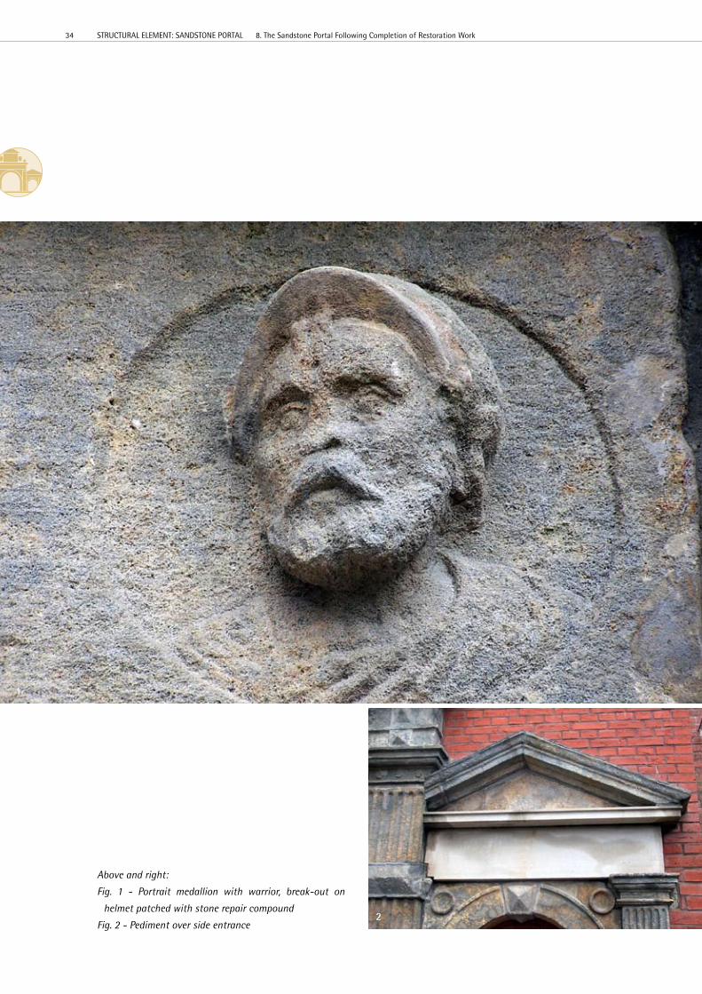
Above and right:
Fig. 1 - Portrait medallion with warrior, break-out on
helmet patched with stone repair compound
Fig. 2 - Pediment over side entrance2
1
34 STRUCTURAL eLeMeNT: SANDSTONe PORTAL 8. The Sandstone Portal Following Completion of Restoration Work
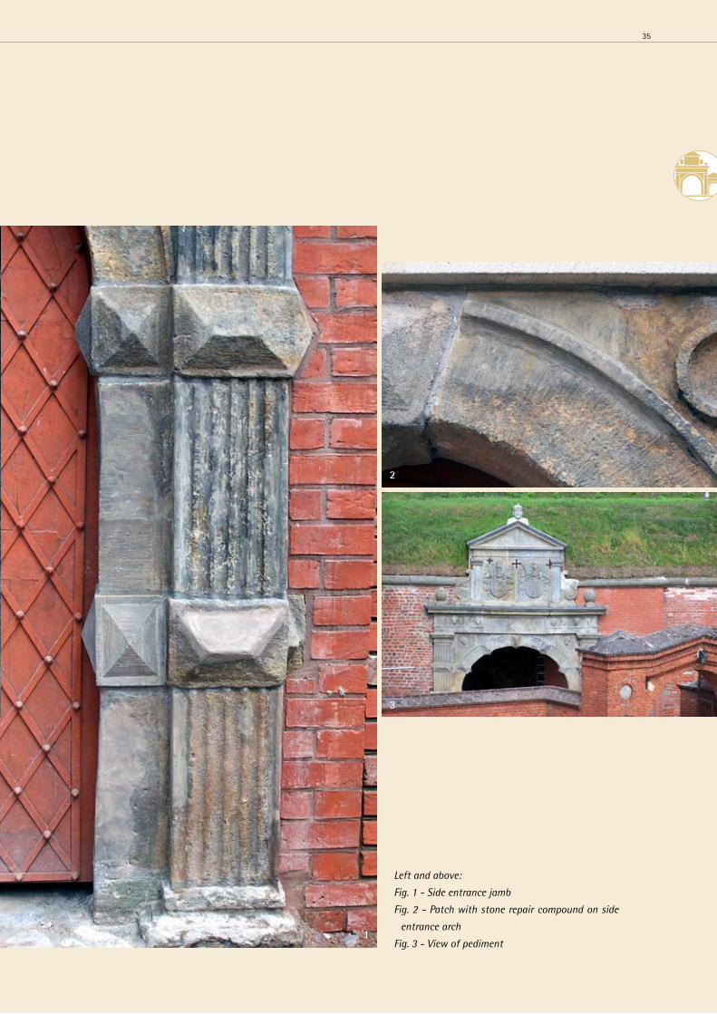
Left and above:
Fig. 1 - Side entrance jamb
Fig. 2 - Patch with stone repair compound on side
entrance arch
Fig. 3 - View of pediment1
2
3
35
Bibliography
BOLZe, Th. / SChUBeRT, Th.: Modernisierung und
Instandsetzung der Festung Dömitz – Modellprojekt
Sanierung Sandsteinportal, Potsdam, Berlin 04.04.2006
Working group: Thomas Bolze, engineer, and Thomas
Schubert, restorer
GRUNeRT, S.: Der Sandstein der sächsischen Schweiz.-
Paper from the Staatliches Museum für Mineralogie und
Geologie in Dresden, Volume 37, Leipzig 1986
KUTSChKe, D.: Steinbrüche und Steinbrecher in
der Sächsischen Schweiz – Series published by the
Stadtmuseum Pirna, Issue 11, Pirna 2000
NeUMANN, h.: Festungsbau - Kunst und Technik, Weltbild
Verlag Gmbh, Augsburg 2000
SChARNWeBeR, J.: Festung Dömitz im 1000jährigen
Mecklenburg, Druck- und Verlagsgesellschaft Köhring &
Co., Lüchow 1995
SChARNWeBeR, J.: Die Festung Dömitz, ein Ort für
mecklenburgische Militärgeschichte? in Der Festungskurier,
Volume I, Ingo Koch Verlag, Rostock 2001
SChRÖDeR, J.: Gutachten – ergänzende Dokumentation
zu der Untersuchung zum erhaltungszustand
und den Untersuchungsergebnissen am
Festungsportal; Denkmalpflegerische Zielstellung und
Sanierungsempfehlung, Rostock, Nov/Dec 2003, Jörg
Schröder, restorer – VDR (German association of restorers)/
Rostock.
List of Parties Involved
Project leadership:
GOS mbh - Treuhänderischer Sanierungsträger (fiduciary
redevelopment agent) for the town of Dömitz, Manfred
Kersten
Construction supervision:
Architekturbüro Michael e.A. Porep (architecture
firm)
State Agency for the Preservation of historical Landmarks,
Lower Authority for historical Sites
Preliminary Investigations – Structural Survey
– Restoration Concept
Working group
Thomas Bolze (engineer), Potsdam
Thomas Schubert (restorer), Berlin
together with
Dr. Angela ehling, geologist, Federal Institute for
Geosciences and Natural Resources (BGR), Berlin office
– petrographic analyses
FeAD Gmbh - Forschungs- und entwicklungslabor für
Altbausanierung und Denkmalpflege, Berlin – mortar and
salt analyses
Gudrun Bolze, Ingenieurbüro Bolze (engineering firm),
measurements and structural diagrams
Restoration of the Portal
Working group
Thomas Bolze (engineer), Potsdam
Thomas Schubert (restorer), Berlin
together with
FeAD Gmbh - Forschungs- und entwicklungslabor für
Altbausanierung und Denkmalpflege, Berlin – reduction of
the salt content
Steinwerkstatt Alexander Reichelt (stone workshop),
master stonemason and restorer, Potsdam – stonemasonry
work
Claudia Arnold M.A., art historian, Berlin – documentation
of restoration work
Philipp Bolze, Restaurierungswerkstatt Thomas Schubert
(restoration workshop), master plumber and metal restorer
– plumbing work
Kathrin Stein, Restaurierungswerkstatt Thomas Schubert
(restoration workshop)
Anett Lüdicke (restorer), Ingenieurbüro Bolze (engineering
firm)
Gudrun Bolze, Ingenieurbüro Bolze (engineering firm)
Appendix
36 STRUCTURAL eLeMeNT: SANDSTONe PORTAL Appendix
Publisher:
Town of Dömitz
Goethestrasse 21, 19303 Dömitz, Germany
www.doemitz.de
www.festung-doemitz.de
Tel. +49 (0) 3 87 58 - 3 16 0
Fax +49 (0) 3 87 58 - 3 16 55
GOS mbh
Treuhänderischer Sanierungsträger
(fiduciary redevelopment agency)
for the Town of Dömitz
Platz des Friedens 2, 19288 Ludwigslust, Germany
www.gos-gsom.eu
Tel. +49 (0) 38 74 - 57 08 00
Fax +49 (0) 38 74 - 4 73 46
e-mail: [email protected]
Editors:
Annette Brandes, GOS mbh
Manfred Kersten, GOS mbh
Imprint
STRUCTURAL eLeMeNT: SANDSTONe PORTAL Imprint
Texts:
Thomas Bolze (engineer)
Bruno-Taut-Strasse 7C, 14469 Potsdam, Germany
Tel. +49 (0) 3 31 - 270 47 25
Fax +49 (0) 3 31 - 270 46 79
e-mail: [email protected]
Photographs and illustrations:
All photographs were taken by Thomas Bolze (engineer),
Potsdam, during the construction period from 2005
to 2007 (unless otherwise credited).
Graphics:
www.designmuehle.com
Printing:
Digital Design, Schwerin
November 2007, 1st edition, 500 copies
Previous Publications:
Issue 1 “Festung Dömitz” with chronological table
- December 2006, 1st edition, 500 copies
Issue 2 “Festung Dömitz” Bauteil Sandsteinportal
- Mai 2007, 1st edition, 500 copies
Scientific partners:
european University - Viadrina Frankfurt/Oder
R. S. Dornbusch, M.A.
www.ziw.euv-frankfurt-o.de/sek/
humboldt-University at Berlin
Dr. F. Riesbeck
www.agrar.hu-berlin.de
Immanuel Kant State University of Russia
Dr. e. Kropinova
www.albertina.ru
Vytautas Magnus University Kaunas
Dr. V. Rakutis
www.vdu.lt
Kaunas University of Technology,
Institute of Architecture and Construction
Dr. K. Zaeckis
www.asi.lt
37
Contact:
City of Kostrzyn, Lead Partner
Mrs. Agnieszka Żurawska-Tatała
Tel. +48 (0) 95 - 7 27 81 24
Fax +48 (0) 95 - 7 27 81 93
e-mail: [email protected]
Projekt Coordination:
hartmut Röder
Tel. +49 (0) 30 - 92 37 21-0
e-mail: [email protected]
Dr. hans-Rudolf Neumann
Tel. +49 (0) 30 - 31 47 23 88
e-mail: [email protected]
Projekt Homepage:
www.bfr.pl

Fortification Town partners:
Kostrzyn nad Odrą - Fortress Kostrzyn
Municipality of Kostrzyn nad Odrą
www.kostrzyn.um.gov.pl
Dömitz - Fortress Dömitz
Municipality of Dömitz
www. doemitz.de
Berlin - Citadel Spandau and Fort Hahneberg
Department Spandau of Berlin (Citadel of Spandau)
www.zitadelle-spandau.de
Peitz - Fortress Peitz
Association Museum of City Peitz
Förderverein für die Museen der Stadt Peitz e. V.
www.museumsverein-peitz.de
Gorgast - Fort Gorgast
Association “Fort Gorgast”
www.fort-gorgast.de
Kołobrzeg - Fortress Kołobrzeg
Municipaly of Kołobrzeg
www.kolobrzeg.pl
Gdańsk - Fort Grodzisko
Culture Park of City Fotifications, Fortress Gdańsk
www.grodzisko.pl
Gdańsk - Fortress in Vistulamouth
Historical Museum of Gdańsk
www.mhmg.gda.pl
Nowy Dwór Mazowiecki - Fortress Modlin
Municipality of Nowy Dwór Mazowiecki
www.nowydwormaz.pl
Giżycko - Fortress Boyen
Municipality of Giżysko
www.gizycko.pl
Świnoujście - Fortress Świnoujście
Municipaly of City Swinoujscie
www.swinoujscie.pl
Kaunas - Fortress Kaunas
Municipality of City Kaunas
www.kaunas.lt
Kaliningrad - Fortress Kaliningrad
Kaliningrad Oblast Administration
www.gov.kaliningrad.ru