Embed Size (px)
Citation preview

A newsletter from the
Issue Issue Issue Issue 66669999 ((((JanJanJanJan ---- JunJunJunJun 2020202011114444))))
Contents
Editor's Note ♦
Basic Phenomena inside Thermal Plasma Torch and General Issues ♦
Development of 1kW Microwave Plasma Arc source for Gasification and other tailored applications
♦ Development of 50 kW IGBT based Power Supply
♦ Other News

Editor's note Ms. Vidhi Goyal discusses about the basic phenomenon of the thermal plasma torch and the issues associated. She describes about the steps taken by FCIPT to address those issues and the experimental set up developed for this purpose. Mr. Vishal Jain, cites about the development of 1kW Microwave plasma arc source at FCIPT. He describes the advantages of the microwave plasma torch and its various tailored applications. He also emphasizes about the microwave plasma torch demonstration with different plasmagen gases. The study on coal gasification with steam as gasifiying gas using microwave torch is been discussed. Mr. Bhupendra K Patel presents about the development of 50kW IGBT based power supply at FCIPT. In this article he presents about the working principle of IGBT based power supply its advantages over Diode based power supply. He also states about the benefit of the power supply to generate the high current DC for the plasma torch load with high efficiency. Editor: Dr. S. Mukherjee Co-Editor: P.Vadivel Murugan Conference/Poster presentations from FCIPT Name of the author Topic Date Place Conference
Sagar Agrawal, Ramkrishna Rane, Subroto Mukherjee
CZTS: Low cost solar cells by magnetron sputtering
20 Jan 2014 Ahmedabad SSPC 2014 (The Society for Surface Protective Coating
India)
Dr. S.K Nema Advanced Plasma Based Technologies for Surface
Modification”
21-22 February
2014
Jaipur RTRSC2014 (National Conferen
ce on Recent Trends in Chemical
Sciences) Dr. S. K Nema Biomedical Waste Disposal
and Syn Gas Recovery from Petroleum Waste using
Thermal Plasma Technology
13-15 February
2014
Pune N-SEPMI 2014 (National
Symposium on Emerging Plasma Techniques for
materials processing and
industrial applications)

ABOUT FCIPT
Facilitation Centre for Industrial Plasma Technologies
The Institute for Plasma Research (IPR) is exclusively devoted to research in plasma science, technology and applications. It has a broad charter to carry out experimental and Theoretical research in plasma sciences and emphasis on the physics of magnetically confined plasmas and certain aspects of nonlinear phenomena. The Institute also has a mandate to stimulate plasma research activities in the universities and to develop plasma-based technologies for the industries. It also contributes to the training of plasma physicists and technologists in the country. IPR has been declared as the domestic agency responsible in INDIA to design, build and deliver advanced systems to ITER (International Thermonuclear Experimental Reactor) to develop nuclear fusion as a viable long term energy option. The Facilitation Centre for Industrial Plasma Technologies (FCIPT) links the Institute with the Indian industries and commercially exploits the IPR knowledgebase. FCIPT interacts closely with entrepreneurs through the phases of development, incubation, demonstration and delivery of technologies. Complete package of a broad spectrum of plasma-based industrial technologies and facilitation services is offered. Some of the important areas in which FCIPT has been working on include Plasma Surface Engineering, Plasma Pyrolysis/ Gasification/ Energy Recovery, Plasma Diagnostics, Plasma Based Nano Patterning and Nano Synthesis, Textile Engineering, Solar Cell Development, etc. This newsletter is designed to update the readers with the latest developments in the important field of plasma processing and plasma based technology development and to look for new industrial opportunities. Please visit our website: http://www.plasmaindia.com
Basic Phenomena inside Thermal Plasma Torch and General Issues Ms. Vidhi Goyal
Introduction: The thermal plasma torch is a device which works in the arc plasma regime, and has large number of industrial applications like cutting, welding, spraying, synthesis of nano-particles etc.
because it is a cheap and clean source of high heat flux. But plasma inside a non-transferred plasma torch undergoes many complex processes due to interaction among electromagnetic, thermal and flow fields, giving rise to fluctuations of plasma column depending on the regime of operation [1]. The growth of thermal plasma technologies is mainly hampered due to lack of control on these fluctuations. Minor changes in experimental parameters result in drastic changes in the characteristics of the plasma, giving rise to different voltage modes such as steady, takeover and restrike. A complete understanding of this phenomenon is long awaited and is believed to have a strong impact on the growth of thermal plasma technology. However, no satisfactory theory is available that can predict the measurable fluctuations observed in such devices [2]. Fluctuations observed experimentally in such devices are analyzed using tools of dynamical analysis and found to follow a gradual transition from the non-chaotic to chaotic regime under variation in control parameters. It has been reported earlier that forces such as gas-drag force, thrust force and electromagnetic forces compete with each-other, decide the position of arc root attachment and govern the nature of fluctuations. In any arc plasma device, an arc is established between anode and cathode through some flowing gas and converts the gas into plasma through ohmic heating. This is then used for associated processing work. Arc starts from the cathode, proceeds through the current channel in the gas and finally joins the anode at some position. Associated electromagnetic forces, guide the

current to enter anode normally at the arc root. On application of dc voltage along with HVHF (for igniting arc), an arc is established between the cathode and the anode. Generally cathode is a water-cooled thoriated tungsten rod or a button with a tapered tip. The tip is thoriated to bring down the work function for efficient emission of electrons. Either through thirmionic or field emission or both, electrons are emitted from this tip and passed though the gas constituting a current channel called an arc which moves on the surface of the cathode due to the emission process, cathode jets, and electromagnetic forces. However, the cathode surface is much smaller in size and the effect on the voltage, optical, and acoustic emission is dominantly from the anode arc root dynamics. The intense external cooling provided creates a cold boundary next to the anode. As arc is established, the entire current passes through a small cylindrical zone (area;mm2) which electrically connects the main arc to the electrode. Since the current densities are extremely high (;kA/cm2), this region is heated with temperature of the order of thousands of K through intense ohmic heating. The energy input to the anode spot is roughly balanced by evaporation and a nearly constant temperature is maintained on the surface. The anode spot temperature is above boiling point for most materials and therefore, a high vapor pressure exists for the material evaporated. The evaporated material strongly diffuses into the zone near arc root [2]. Because of the tiny area of the spot, extremely high current density appears in the region. This in association with self-magnetic field produces a compressive force on the current carrying plasma column just above the anode spot [2]. The compressive force results in increased current density that in turn generates more heat and tries to counteract the compressive force. All these together make the near arc root region a highly nonlinear system with complicated time dependence. The degree of complication depends on the arc current and existing temperature of the near arc root zone because of that intrusive diagnostics like Langmuir probe is not possible for this kind of plasmas [3].
To address these issues plasma torch Lab has been set-up at FCIPT and experiments are going on to characterize the torch and to explore its operational regime with respect to various parameters like gas composition, current, geometry of the device etc. Experimental Set-up: Experiments are performed with Plasma Torch (T-2) at Plasma Torch Lab in FCIPT premises. There exist three type of stabilization mechanisms like wall, gas and magnetic field stabilization for protecting device and confining arc plasma. Nitrogen is used as working gas and all the experiments are performed at atmospheric pressure using de-mineralized water as coolant in presence of external magnetic field ranging 0G – 500G and gas flow rate ranging 20lpm – 100lpm.Thoriated tungsten and copper are the materials of cathode and anode respectively. Constant current DC power supply is used as power source with rating (430V- 250A). A HVHF circuit is used for igniting the arc. Temperature is captured using T type thermo couples, current using current probe and Voltage using Tektronix high voltage probe.
Experimental set-up
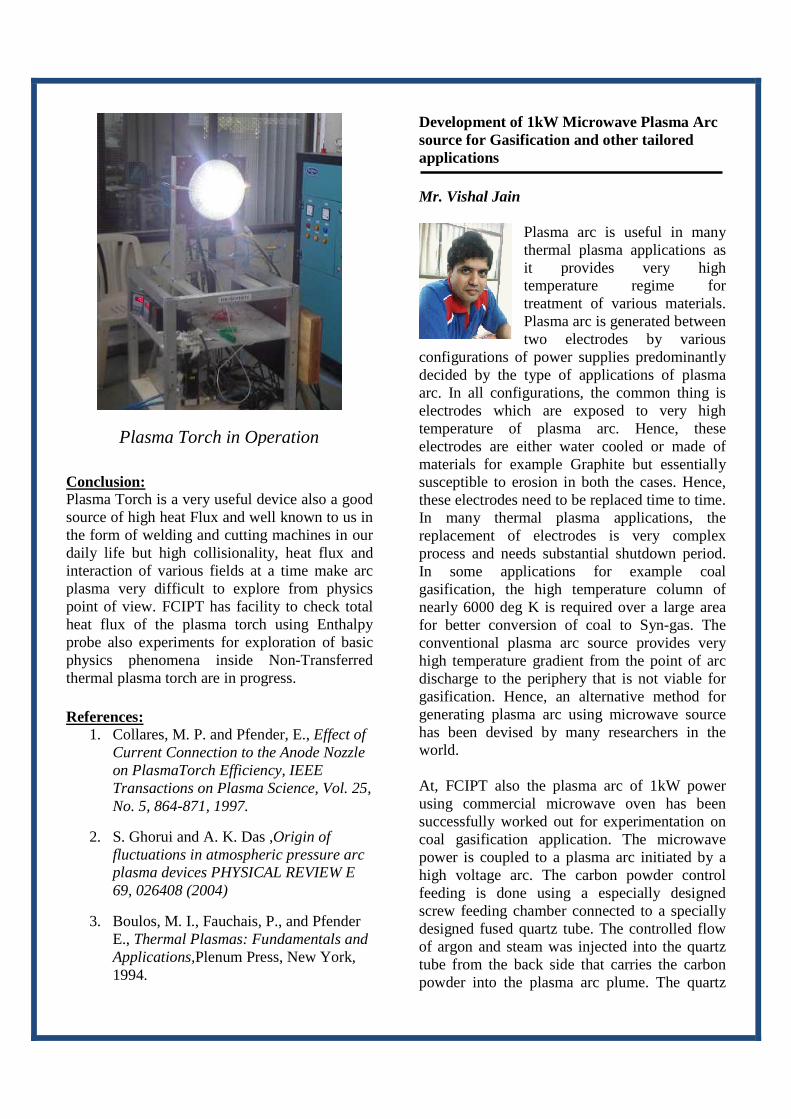
Conclusion: Plasma Torch is a very useful device also a good source of high heat Flux and well known to us in the form of welding and cutting machines in our daily life but high collisionality, heat flux and interaction of various fields at a time make arc plasma very difficult to explore from physics point of view. FCIPT has facility to check total heat flux of the plasma torch using Enthalpy probe also experiments for exploration of basic physics phenomena inside Non-Transferred thermal plasma torch are in progress. References:
1. Collares, M. P. and Pfender, E., Effect of Current Connection to the Anode Nozzle on PlasmaTorch Efficiency, IEEE Transactions on Plasma Science, Vol. 25, No. 5, 864-871, 1997.
2. S. Ghorui and A. K. Das ,Origin of fluctuations in atmospheric pressure arc plasma devices PHYSICAL REVIEW E 69, 026408 (2004)
3. Boulos, M. I., Fauchais, P., and Pfender E., Thermal Plasmas: Fundamentals and Applications,Plenum Press, New York, 1994.
Development of 1kW Microwave Plasma Arc source for Gasification and other tailored applications Mr. Vishal Jain
Plasma arc is useful in many thermal plasma applications as it provides very high temperature regime for treatment of various materials. Plasma arc is generated between two electrodes by various
configurations of power supplies predominantly decided by the type of applications of plasma arc. In all configurations, the common thing is electrodes which are exposed to very high temperature of plasma arc. Hence, these electrodes are either water cooled or made of materials for example Graphite but essentially susceptible to erosion in both the cases. Hence, these electrodes need to be replaced time to time. In many thermal plasma applications, the replacement of electrodes is very complex process and needs substantial shutdown period. In some applications for example coal gasification, the high temperature column of nearly 6000 deg K is required over a large area for better conversion of coal to Syn-gas. The conventional plasma arc source provides very high temperature gradient from the point of arc discharge to the periphery that is not viable for gasification. Hence, an alternative method for generating plasma arc using microwave source has been devised by many researchers in the world. At, FCIPT also the plasma arc of 1kW power using commercial microwave oven has been successfully worked out for experimentation on coal gasification application. The microwave power is coupled to a plasma arc initiated by a high voltage arc. The carbon powder control feeding is done using a especially designed screw feeding chamber connected to a specially designed fused quartz tube. The controlled flow of argon and steam was injected into the quartz tube from the back side that carries the carbon powder into the plasma arc plume. The quartz
Plasma Torch in Operation
tube is inserted into a cavity of tapered waveguide WR284. The tapering of waveguide is done to enhance the electric field for better power coupling. The center line axis of quartz tube is kept at certain length from the dead end in the tapered waveguide. This length is quarter the wavelength of the microwave for coupling maximum reflected power from the dead end into the plasma plume. The magnetron source of commercial microwave oven has two supplies from the power source. One AC supply is connected to the coil that draws nearly 4A current while another supply is a high voltage half bridge DC supply connected to coil cathode and grounded body anode. The system for experimentation is shown in the figure below.
Figure 1: Microwave plasma arc system at FCIPT
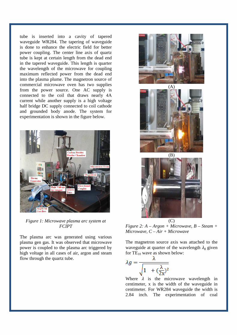
The plasma arc was generated using various plasma gen gas. It was observed that microwave power is coupled to the plasma arc triggered by high voltage in all cases of air, argon and steam flow through the quartz tube.
(A)
(B)
(C)
Figure 2: A – Argon + Microwave, B – Steam + Microwave, C – Air + Microwave The magnetron source axis was attached to the waveguide at quarter of the wavelength �g given for TE10 wave as shown below:
Where � is the microwave wavelength in centimeter, x is the width of the waveguide in centimeter. For WR284 waveguide the width is 2.84 inch. The experimentation of coal

gasification is being performed using the system shown in figure 1. The coal feed of nearly 1kg/hr is targeted in present experiments. The steam flow of nearly 10 – 20 lpm would be required for the above coal feed. The initial plasma arc with coal and steam flow in microwave discharge is shown in figure 3 A.
(A)
(B)
Figure 3: (A) - Microwave Plasma Arc with coal feed and air flow with steam flow in controlled
quantity,(B) – Schematics of the coal gasification The microwave plasma arc can also be applied for experimentation for many tailored applications for example diesel engine exhaust gas treatment, carbon nano powder formation,
butadiene decomposition for petrochemical industries, plasma arc generation under high pressure flow conditions. At FCIPT, the detail experimental study of steam flow optimization with carbon powder feed into the microwave plasma arc plume is under execution for generation of Syn-gas (CO + H2) that will be taken to some burner and gas collecting pump for gas quality testing using GC. Development of 50 kW IGBT based Power Supply Mr. Bhupendra K Patel
Introduction: Switching Mode Power Supply is advance technique for compact, efficient and ripple free DC power supply. It has significantly reduced the
transformer size and hence, the losses which take place in conventional DC supply. The plasma torch demands DC with constant current source, in order to withstand low impedance arc load. Coupling such low impedance and highly dynamic load to IGBT based supply for continuous operation is a challenging task. The major drawbacks of the conventional Diode rectifiers are overcome in IGBT based Power Source. This further provides the benefits to power factor and compact size of power supply. The plasma arc is a non-linear and dynamic load; the nature of non-linear load, generate harmonics (high frequency components) in the current waveform in the source. This distortion of the current waveform leads to distortion of the voltage waveform. Under these conditions, the power factor becomes poor and efficiency becomes very less. In the plasma torch load, during the initial condition, when the anode and cathode electrodes are at short circuit with each other, the inrush current is too high. This condition creates an odd harmonics in the line current. However, the harmonics of each phases are always in phase so they are additive and may lead to serious neutral loading problems. The

conventional technology contains the high impedance transformer and diode bridge rectifier to generate the high current DC for the plasma torch load. The nature of the Plasma load in a non-liner type as mention above the harmonics generated at line current which cause of poor power factor. The DC is generated using the full bridge diode configuration it creates very large ripple and also because of very high DC power large size of filters are required. Thus the supply becomes extremely large. Under this case, the transformer is heavy and power conversion efficiency is poor. To overcome these problems the IGBT base constant current source is introduced. The technology is presented here is based on switching mode power supply principle. It has a very low ripple factor due to high frequency link and also having a good control over a load current because the IGBT’s duty cycle is controlled using current mode PWM controller. Block Diagram:
The block diagram of the power supply is shown in the above figure. The basic principle of the current contol mode operation is based on a high frequency link in DC to DC conversion called as Switching Mode Power Supply (SMPS). The high switching frequencies reduces the size of the power transformer and associated filtering components in the power supply. The working principle of the supply is as follows:
• An AC to DC converter using 3 ø full wave bridge diode configurations which converts the 3 ø incoming mains to a DC voltage. Here the uncontrolled bridge rectifier is used because the torch voltage
depends on the gap between the electrodes only.
• A DC to AC inverted using the IGBT based full bridge topology. The switching of the Semikron make SKM300GB128D IGBT inverts the DC power into the high frequency AC.
• The high frequency AC is now step downed using HF transformer and then the ultra fast reverse recovery diodes are used as full wave rectifier to convert the AC to DC at high frequency.
Here the IGBT based power supply runs in to full bridge topology because of required higher power rating. The IGBT losses are reduced by deploying ZVS (Zero Voltage Switching) by adopting a above resonance technique in which the switching frequency is slightly higher than the resonance frequency. The parallel diode is in conducting mode when the IGBT is switched on and hence, it is called zero voltage switching under full wave mode of operation. The VDC is applied to the IGBT based full bridge inverter. The IGBT pair are turned on and off simultaneously during alternate half cycles. The driver of the IGBT contains the peak current sensing voltage comparator and generates the PWM according to set current. The line and load current are regulated by varying IGBT’s ON and OFF time. The high frequency step-down transformer is used to convert the 650/200 Vdc. The transformer having a amorphous metal core usually operated on 20 kHz frequency range. The HF transformer is usually a center-tap type. The two ultra fast recovery epitaxial diodes are feeding the load with full wave rectification mode. The center tap transformer is chosen because it provides a good flux balancing at very high current in the transformer. The output capacitor is selected to meet output ripple voltage specifications. To get more efficient we can employ two stage filters at DC output.

Comparison between High Impedance power supply and IGBT based power supply
Sr. No.
Description IGBT based Power Supply
Diode Based Power Supply
1 Technology
IGBT based S.M.P.S using Full-Bridge topology to control the load current
High Impedance transformer to control the load current
2 Regulation
Can regulate the power supply with minimum harmonics
Can regulate the power supply but high harmonics are generated
3 Efficiency Efficiency is more than 90%
Efficiency is 55% - 60% only.
4 Power Factor
The power factor is very good without introducing a PFC
This type of power supply has a very poor power factor.
5 Ripple
The ripple factor is very less due to high frequency AC rectification
The ripple factor is high
6 Construction
Compact design with very less weight
Bulky and large
7 Up-scaling
There is a high possibility to increase the power capacity up to 500kW
The losses incurring in the transformer is a major constraint for large
with using the same topology
power system of similar topology
8 Cost Less More
9 Cooling Water cooling for IGBT
Forced Air cooling of the transformer and the diode stack
Conclusion: The comparative study of the two topologies depicts that the IGBT based supply is favourable topology especially when the very high power demand is there for plasma torch operation. IGBT based power supply adopts high frequency resonant converter for the power transfer in which the main advantages are size reduction, low cost, higher efficiency (because of low losses) and better power factor. On other hand the high impedance transformer has disadvantages like bigger size, high cost, low efficiency (because of heavy power losses) and poor power factor. So in order to work at very high power the IGBT based supply is the most suitable option. FCIPT have started designing 50 kW IGBT based supply. OTHER NEWS Technology Awareness Workshop FCIPT with Man Made Textile Research Association (MANTRA), Surat organised a Technology Awareness Workshop in association with Department of Science and Technology, New Delhi at MANTRA, Surat on 26.02.2014. Local textile industry people were invited for the workshop and provided the awareness about the plasma applications in textile.

Procurement of High Temperature X-Ray Diffraction System
Recently a High Temperature XRD machine of BRUKER made was procured and installed at , installed at FCIPT, IPR. This instrument can analyse only powder samples. Powder particles with less than 10µ size are preferable. With the additional HT module, it is possible to study the phase transformations at various temperatures (from 30 to 1200° C). However, the sample should be in the form of a compacted pellet (of typically 10 mm diameter and 0.8 mm thick) for the high temperature XRD studies. Some of the salient features of this instrument are mentioned below;
• Phase analysis of various materials (in
the powder form) such as steels, superalloys, ceramics etc.
• The XRD data can be used for phase analysis (qualitative & quantitative) and calculation of crystallite size
• High temperature XRD studies can be done from 30 to 1200 °C at different time and different temperature intervals
Photo image of D8 Discover diffractometer installed at FCIPT
FCIPT Day On the occasion of FCIPT’s fourth year anniversary in new premise, a series of lectures were arranged for PhD scholars and JRFs working at FCIPT on 10th Feb 2014. The lectures were classified as three main themes namely:
a) Nanotechnology b) Materials and Metallurgy c) Plasma Physics. Prizes were awarded for the best presentation at the end of the event.
Dr.S. K. Nema, giving a technical presentation about the plasma application in textile
Demonstration of plasma treatment system developed by DST funding

Group photo taken on the memorable event of FCIPT day
Facilitation Centre for Industrial Plasma Technologies Institute for Plasma Research Phone :(079) 23269000/23269002 :23962000 A-10/B, Sector-25, Fax :(079) 2326901/23962001 GIDC Electronic Estate, E-mail :[email protected] Gandhinagar, Gujarat-382 044 Website :www.plasmaindia.com INDIA