Embed Size (px)
Citation preview
SYSTEMS SUPPORTING PRODUCTION ENGEINEERING 2013
49
5
ISSUE OF MULTIPLE-LAYER WINDING OF ROPES ON DRUMS OF MINE-SHAFT HOISTINGS
5.1 INTRODUCTION
Multi-layer winding of ropes on cylindrical drums of hoisting machines, which are used
in the shaft hoists, presently is widely used in many countries around the world (Republic of
South Africa, Canada, England, Russia, Ukraine, Germany, etc.) in stationary deep hoisting
devices and in winders for shaft sinking and in auxiliary emergency-rescue shafts. In Poland,
the Mining Mechanization Center KOMAG in Gliwice, and Shaft Sinking Company in
Bytom, already in the 70’s of last century, have concentrated on issue of the multi-layer
winding of ropes on drums of the mining winders [1, 5, 9, 13, 14, 15]. Currently in Poland,
after decades of interruption, again there began to new shaft sinking or to shafts sinking to a
depth of 1200 m of shafts, existing in coal mining. Therefore, there have appeared some
problems connected with kinematics of winding and ropes’ wear during their multi-layer
winding.
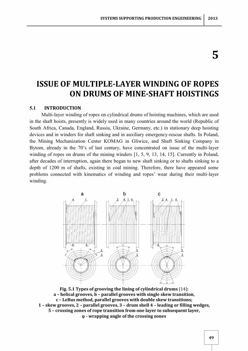
Fig. 5.1 Types of grooving the lining of cylindrical drums [14]:
a – helical grooves, b – parallel grooves with single skew transition, c – LeBus method, parallel grooves with double skew transitions;
1 – skew grooves, 2 – parallel grooves, 3 – drum shell 4 – leading or filling wedges, 5 – crossing zones of rope transition from one layer to subsequent layer,
- wrapping angle of the crossing zones

2013 Editor: KAŹMIERCZAK J.
50
In the country, a multi-layer winding of ropes was used and is still using, mainly in the
winders for shaft sinking and in auxiliary, emergency, rescue and inspection shafts. In
practice, multi-layer winding of ropes is applied on smooth-faced drums (abandoned in
mine-shaft hoists) or in drums with the lining in which grooves are made. There is also
applied direct grooving of drum shells. There can be distinguished three basic types of drums
grooving and winding of ropes, fig. 5.1: helical, parallel with the single skew transition, and
parallel LeBus method with double skew transitions. In the LeBus method one can distinguish
LeBus synchronous and LeBus asynchronous grooving.
Helical grooving consists of the continuous spiral, which assure continuous winding at
the one layer of rope, fig. 5.1a. Formerly, this type of grooving was also applied to multi-layer
winding. However, due to a number of adverse effects, such as: wedging of the rope at the
rims of a drum, disordered winding, seizure of rope, causing dangerous dynamic forces within
the rope and its destruction, presently it is used exceptionally and only there, where parallel
winding cannot not be applied e.g. in machines with grooves incised in the drum shell.
Therefore, helical grooving is used only for one-layer or two-layer winding, however
practically it is used in the winding of few layers.
Parallel grooving consists of grooves made parallel to the rims with one zone of skew
grooves (fig. 5.1b), where the rope displaces by one pitch of winding corresponding to (d+),
where d – diameter of the rope, – slit between the coils of rope. In order to improve the rope
transitions to next layer, there are placed directing-uplifting wedges in that zone.
The necessary condition for satisfactory operation of machine with multi-layer winding
of rope on a drum is regular smooth compact and ordered winding of rope, both in the first, as
in the subsequent layers. If the winding is irregular, there is a possibility of breakdown of rope
through the already wound layer and placement on the lower improper layer, as well as the
possibility of wedging of the rope at the rim of the drum, what causes an occurrence of strong
jerks in the rope, transmitting on the mining vessel and causing its vibrations.
As a result of wedging the rope and vibrations caused by transition of rope from layer to
layer and from coil to coil, the durability of the rope decreases, as the result of wear and
cracking of wires. It should be noted, that the compact and ordered rope winding in the first
layer of lining grooves influences on proper winding of the next layers, and simultaneously
for the safe exploitation of the shaft hoists. The problem of multi-layer winding of ropes on
drums of winders includes three issues:
strength of the drums during multi-layer winding,
kinematics (behavior) of rope during winding,
durability and wearing of the hoisting rope, related to the selection of the rope lay.
In this paper, based on literature, methods of ropes winding, particularly LeBus method,
are presented.
5.2 ROPE WINDING IN THE HELICAL GROOVES
One methods of multi-layer winding of rope is its winding on the drums, which are
equipped with lining of grooves incised according to helical (screw) line.
The first layer of rope on the surface of cylindrical drum with incises grooves,
according to helical line winds fluently and regularly. This type of winding lasts until the

SYSTEMS SUPPORTING PRODUCTION ENGEINEERING 2013
51
penultimate coil inclusive, until the last line of coil will not encounter to the gap having
wedge’s shape created by rims’ wall of drum, and the penultimate coil, fig. 5.2. In this, so-
called critical place of drum rope gradually picks up on the second layer of winding. Rope, to
get in the state of equilibrium, abandons the critical place of a drum and places between the
coils of first layer, i.e. between the penultimate and adjacent, remaining there until it comes
up again to a critical place of the drum [3, 13].
Fig. 5.2 Two-layer winding of rope on cylindrical
drum with lining with helical grooves [13]
Then rope again rises from the groove formed by two adjacent coils and performs the
second pitch displacement along the drum’s generatrix. Such continual, pitch displacement of
rope on the second layer of winding is done twice during in each rotation of the drum, fig. 5.3
[7].
Fig. 5.3 Development of surface of the winding of drum lining with spiral grooves [4]
2013 Editor: KAŹMIERCZAK J.
52
On the spiral grooves in the range of multi-layer winding, the coils of odd layers are laid
according to the helical line, and in the even layers rope does the double pitch of displacement
from coil to coil, during each rotation of a drum. In critical places next to the rims of drum
wedging of the rope and disordered winding of rope occurs, contributing to cause dangerous
dynamic forces in the rope. It has very negative influence on a durability of rope and may also
cause damage of drum rims. Due to safety reasons, rope transition from layer to the next
layer, must occur with limited or reduced winding speed.
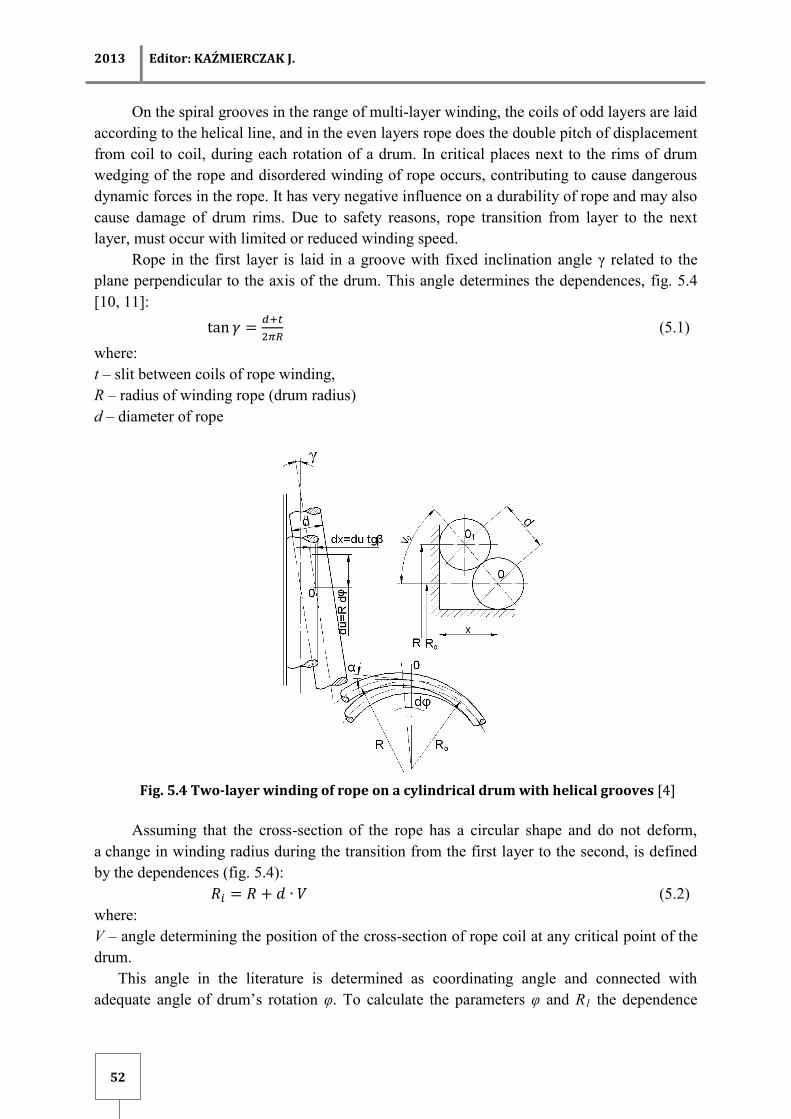
Rope in the first layer is laid in a groove with fixed inclination angle γ related to the
plane perpendicular to the axis of the drum. This angle determines the dependences, fig. 5.4
[10, 11]:
(5.1)
where:
t – slit between coils of rope winding,
R – radius of winding rope (drum radius)
d – diameter of rope
Fig. 5.4 Two-layer winding of rope on a cylindrical drum with helical grooves [4]
Assuming that the cross-section of the rope has a circular shape and do not deform,
a change in winding radius during the transition from the first layer to the second, is defined
by the dependences (fig. 5.4):
(5.2)
where:
V – angle determining the position of the cross-section of rope coil at any critical point of the
drum.
This angle in the literature is determined as coordinating angle and connected with
adequate angle of drum’s rotation φ. To calculate the parameters φ and R1 the dependence

SYSTEMS SUPPORTING PRODUCTION ENGEINEERING 2013
53
according to [11] can be used:
and:
(5.3)
This way of rope arranging in a critical position of drum can occur only in a case when
the fleet angle equals zero. Then rope is in the state of equilibrium, if the angle V = π/2, or if
the rope winds itself, or is laid in groove formed by two adjacent rope coils of the first layer.
In reality, in the mine-shaft hoists with drum machines, such position of the rope never
occurs, because during the winding of rope fleet angles are inevitable. Therefore, the rope to
be in the state of equilibrium leaves the critical place of the drum earlier than its boundary
(interval) passing to the second winding layer. This pitch rope displacement along a
generatrix of drum is called first transition of rope, cross-section I-I, in fig. 5.5. During the
further winding of rope, if deviation angles are not excessive (in opposite case a break of coil
of winding rope occurs), rope is laid in the groove created by two adjacent coils of the first
layer (penultimate and the on placed close to it), until the rope will not pass the critical place
of drum again from beginning. It is there again pulled out from the groove formed by two
adjacent coils of winding and performs a second pitch displacement called second transition
(φp – angle of transition) in the second layer of rope, position II-II, fig. 5.5. It results that,
during each rotation of a drum, rope in the second layer performs two pitch displacements
[11].
Fig. 5.5 Diagram of the rope transition from coil to coil during multi-layer
winding on cylindrical drum with helical grooves [7], I-I the first transition (the first pitch), II-II – second rope transition (the second pitch)

2013 Editor: KAŹMIERCZAK J.
54
Behavior of rope during the transition in the second layer of winding (and in the
subsequent layers) is characteristic for multi-layer winding, particularly the two-layer
winding.
5.3 WINDING OF THE ROPE IN PARALLEL GROOVES
Properly multi-layer winding is possible, only with a parallel arrangement of the rope on
the drum rims in incised parallel grooves in the lining or shell drum, or after the appropriate
formation of the first layer of coils on a smooth drum shell. Fundamental condition for the
correctly multi-layer winding is adherence of terminal coils of rope to rims of drum, that there
not exists a possibility of side movement in layers. Irregular layering is caused by absence of
proper side support of rope, which is caused by the incorrect winding width of drum.
Under these conditions, rope has the possibility to perform side movements, wedging
and goes through the lower layer. The incision of parallel grooves in the lining or in the shell
of drum with appropriate width gives the possibility to avoid the rope wedging at the rim of
the drum and also to achieve the proper arrangement of the rope in the winding process at the
rim and in the other coils [13].
In parallel grooved drums, rope performs one pitch in the transition from coil to coil
during each rotation of the drum, both in the first, and in the last layer. To obtain the more
smooth arrangement of the rope in the subsequent layers in the parallel grooves, purposeful
is to make in lining or in the shell of drum, the skew grooves in places of transition from one
coil to next, in which the rope moves along the drum of one diameter of the rope.
Cross-section of wound layers and developed traces of ropes are shown in fig. 5.6.
Analysis of the rope transition from the first layer to the second shows that the rope moves up
and inside, along the generatrix of the drum, by a half diameter of the rope. The nearest
subsequent coil moves also toward the drum interior, but by the full diameter of rope.
Fig. 5.6 Multi-layer winding of rope on cylindrical drum with lining with parallel [7]
The first movement of the first coil of the second layer is departing from the rims of the
drum, leaving the free space equal to a half diameter of the rope.
During the winding of the second coil of the second layer, the rope goes partially
SYSTEMS SUPPORTING PRODUCTION ENGEINEERING 2013
55
through the cross shifting of the first coil, and then through the two coils in the lower layer. At
the end of the second layer, during the transition to the third layer, rope moves up and toward
the rim of drum, by a half of diameter of rope to the position at the rim, above the gap equal to
a half of diameter of rope at the end of second layer. The next coil of third layer moves
toward the interior of a drum by a full diameter of rope. Proper shiftings of rope by a half of
diameter at the rims of drum are in the same direction, whereas shiftings by a full diameter of
rope occur in opposite direction. In further layers winding of rope will go in the same manner,
i.e. in the odd layers as in the first one, and in the even layers as in the second one.
The cross-section which is presented in fig. 5.6 shows, that the even number of layers
contain one coil less than the odd layers. It is caused by a gap equal to a half of diameter of
rope between the terminal coils of the even layer and rims of drum [13].
In each layer the same number of coils can be obtained, when the transition of rope
from layer to layer at the left rim of the drum will be equivalent to transition at the right rim.
It can be fulfilled, when rope during the transition from the last coil of previous layer to the
first coil of next layer will made a pitch equal to half diameter of rope towards the and will
adhere to it. This is achieved by the termination of coils of the first layer at a distance equals
to a half diameter of the rope from the rims of the drum. Each layer starts at the rim of the
drum and it is terminated by upwards movement and displacement in the rim direction, to
form the first coil of the next layer. Coils arrangement is the same as in the previous pattern
[13, 14].
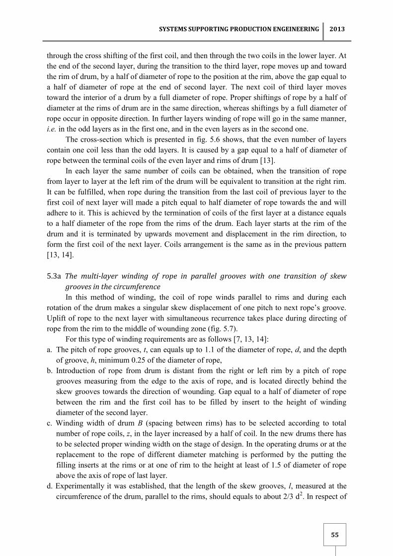
5.3a The multi-layer winding of rope in parallel grooves with one transition of skew
grooves in the circumference
In this method of winding, the coil of rope winds parallel to rims and during each
rotation of the drum makes a singular skew displacement of one pitch to next rope’s groove.
Uplift of rope to the next layer with simultaneous recurrence takes place during directing of
rope from the rim to the middle of wounding zone (fig. 5.7).
For this type of winding requirements are as follows [7, 13, 14]:
a. The pitch of rope grooves, t, can equals up to 1.1 of the diameter of rope, d, and the depth
of groove, h, minimum 0.25 of the diameter of rope,
b. Introduction of rope from drum is distant from the right or left rim by a pitch of rope
grooves measuring from the edge to the axis of rope, and is located directly behind the
skew grooves towards the direction of wounding. Gap equal to a half of diameter of rope
between the rim and the first coil has to be filled by insert to the height of winding
diameter of the second layer.
c. Winding width of drum B (spacing between rims) has to be selected according to total
number of rope coils, z, in the layer increased by a half of coil. In the new drums there has
to be selected proper winding width on the stage of design. In the operating drums or at the
replacement to the rope of different diameter matching is performed by the putting the
filling inserts at the rims or at one of rim to the height at least of 1.5 of diameter of rope
above the axis of rope of last layer.
d. Experimentally it was established, that the length of the skew grooves, l, measured at the
circumference of the drum, parallel to the rims, should equals to about 2/3 d2. In respect of

2013 Editor: KAŹMIERCZAK J.
56
implementation, recommended length of skew grooves should equal to multiplicity of
lining’s width rounded up.
e. Directing wedges are made for rationatization of rope transition to subsequent layer. There
are placed at rims in the zone of skew grooves. Height of wedge with scarf of 15° angle
has to be equal to at least 1.5 of diameter of rope above the geometrical axis of rope of last
layer. Edges of wedges can be cut, and sharp edges should be blunted.
f. Filling inserts are placed in the zone of skew grooves at the rim opposite to rope exit from
the drum and they uplift rope from the first layer into the second one. Height of the inserts
changes from the level of first layer to the level of the second layer. Inserts in the zone of
skew grooves at the exit of rope from the drum and inserts in the zone of parallel grooves
support the coils of second layer. Inserts can be made totally with drum linings, properlu
shaping the lining at the rims or as segements. Filling inserts and directing wedges are
made of hard wood, aliminium, textolit, plastics or steel. Depending on the material used,
they are fixed to the rim, linings or to the shell of drum, by screws, tap bolts, and steel one
can be welded.
Fig. 5.7 Development of surfaces of winding of drum’s lining with parallel grooves
and one skew transition [14]
5.3b Multi-layer winding of ropes in parallel grooves with two transitions of skew grooves
in circumstance of the drum using lebus method
In 1937, Frank LeBus patented the idea of a special grooving of drum lining, which
properly guided the rope during its winding on a drum. This method was developed in 1950,
and in technology it bears the name of the method LeBus. Frank LeBus was a producer of
drilling rigs for the oil mining in Texas. The experiences with difficulties which occurred
during winding multiple layers of rope on drums of drilling rigs, led to patent the new LeBus

SYSTEMS SUPPORTING PRODUCTION ENGEINEERING 2013
57
method, which started to be applied also in other types of winders including mining shaft
hoisting. In mines in USA and South Africa, there began to use the LeBus grooving method
during the winding multiple layers of ropes on cylindrical drums since 1962 [2, 4, 8, 12, 16].
In LeBus method grooves (fig. 5.1c, and 5.8) are made parallel to the rims and the
displacement of coils along the drum by one pitch is obtained by performing skew grooves in
two zones on the circumference of the drum, shifted from each other by 180°. With such
grooved rope moves by a half pitch in one zone, thereby reducing the hitting of rope in the
place of crossing and the possibility of excessive vibrations. Such grooving of LeBus method
called synchronous is particularly useful for winding of mining vessels with a high speed,
during multi-layer winding of more than three layers. Currently this way of grooving, LeBus
synchronous, is the most popular method. To avoid synchronization of rope’s jerks and
vibrations during rotation of the drum, and to reduce the amplitude of harmonic vibrations
(resonance of rope), there was done modification of the LeBus method (fig. 5.8b). It involves
change in the displacement angle φ of skew grooves from 180° to (150° and 210°), (163° and
197°), or any other combination, which gives the sum of 360°. This method of grooving of
lining was called LeBus asynchronous, and it is also widely used (fig. 5.8b).
a)
b)
Fig. 5.8 Schemes of multi-layer winding of ropes on the drums of LeBus method [14]:
a) synchronous, b) asynchronous

2013 Editor: KAŹMIERCZAK J.
58
A necessary condition for satisfactory operation of the machine with multi-layer
winding of ropes on drum is regular, smooth, compact and ordered winding of rope, both in
the first and in subsequent layers. If the winding is irregular, then there is a possibility that
rope will break through the wound layer and will place on lower improper layer. Also there is
possibility of rope wedging at the rims of drum, what causes in rope occurrence of strong
jerks, transmitting on the mining vessel, and causes its vibrations.
As a result of rope wedging and vibrations caused by transition of rope from layer to
layer and from coil to coil, the durability of the rope decreases, as the result of wearing and
cracking of wire. It should be noted, that compact and ordered winding of the first layer of
rope in lining grooves influences on the proper winding of the subsequent layers, and thereby
for the safe exploitation of the shaft hoisting.
5.3c Parallel winding with two skew transitions in circumstance of the drum using
synchronous LeBus method
In the LeBus method coils of rope wind parallel to the rims and during each rotation of
the drum perform double skew displacement of a half pitch t to next rope’s groove. Uplift of
rope to the next layer take place in a zone of skew grooves situated next to the exit of rope
from a drum. Return of rope from the rim to the middle of wound zone (without uplift the
rope) takes place in second zone of skew grooves.
Fig. 5.9 Winding, using the synchronous LeBus method [4]
In zone of skew grooves situated next to the exit of rope from the drum, next to the
opposite rim, inserts uplift the rope from the first to the second layer, and height of these
inserts is changeable from the level of first layer to the level of second layer. However, inserts
SYSTEMS SUPPORTING PRODUCTION ENGEINEERING 2013
59
situated next to rim of the rope’s exit from the drum, have changeable height from the level of
second layer, to the level of third layer. Inserts situated in a second skew zone having an
equivalent height, equals the level of second layer. Inserts can be made as complete with the
lining of drum or in the form of segments [14].
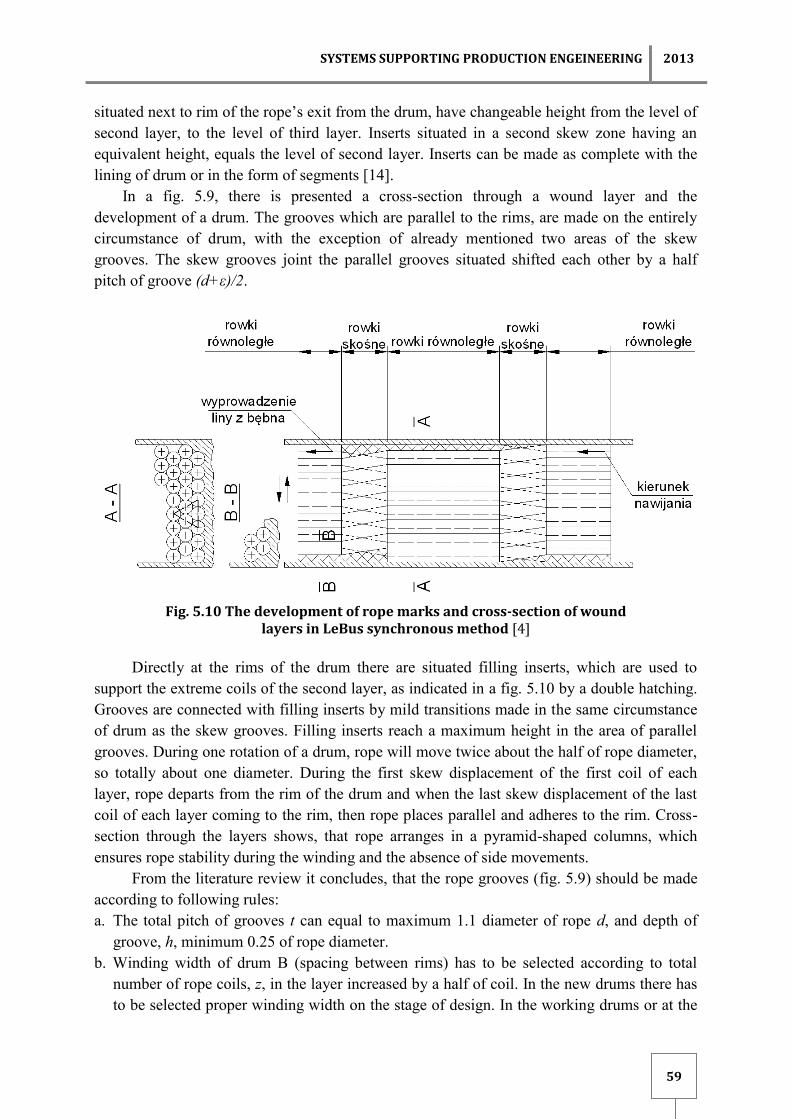
In a fig. 5.9, there is presented a cross-section through a wound layer and the
development of a drum. The grooves which are parallel to the rims, are made on the entirely
circumstance of drum, with the exception of already mentioned two areas of the skew
grooves. The skew grooves joint the parallel grooves situated shifted each other by a half
pitch of groove (d+ε)/2.
Fig. 5.10 The development of rope marks and cross-section of wound
layers in LeBus synchronous method [4]
Directly at the rims of the drum there are situated filling inserts, which are used to
support the extreme coils of the second layer, as indicated in a fig. 5.10 by a double hatching.
Grooves are connected with filling inserts by mild transitions made in the same circumstance
of drum as the skew grooves. Filling inserts reach a maximum height in the area of parallel
grooves. During one rotation of a drum, rope will move twice about the half of rope diameter,
so totally about one diameter. During the first skew displacement of the first coil of each
layer, rope departs from the rim of the drum and when the last skew displacement of the last
coil of each layer coming to the rim, then rope places parallel and adheres to the rim. Cross-
section through the layers shows, that rope arranges in a pyramid-shaped columns, which
ensures rope stability during the winding and the absence of side movements.
From the literature review it concludes, that the rope grooves (fig. 5.9) should be made
according to following rules:
a. The total pitch of grooves t can equal to maximum 1.1 diameter of rope d, and depth of
groove, h, minimum 0.25 of rope diameter.
b. Winding width of drum B (spacing between rims) has to be selected according to total
number of rope coils, z, in the layer increased by a half of coil. In the new drums there has
to be selected proper winding width on the stage of design. In the working drums or at the

2013 Editor: KAŹMIERCZAK J.
60
replacement to the rope of different diameter matching is performed by the putting the
filling inserts at the rims or at one of rim to the height at least of 1.5 of diameter of rope
above the axis of rope of last layer
c. Output of rope from the drum is located at the left or right rim, that a rope adheres to the
rim. The output of rope is located directly behind the skew grooves which uplift the rope
to the next layer towards the winding of rope. Gap equal to half of diameter of rope
(exactly half of pitch of rope groove) between the opposite rims and the last coil of first
layer is filled with an insert at the height of level of second layer. In the second zone of
parallel grooves gap, equal to half of diameter of rope, is laid near the rim of exist of rope
from the drum, i.e. opposite than in the first zone.
d. Company LeBus states, that the length of the parallel grooves should be equal to about
80% of the circumference of a drum, and the total length of the skew grooves to about
20%.
e. Filling inserts are placed in a zone of parallel grooves to support the extreme coils of the
second layer. Height of these inserts equals to the level of second layer.
f. The filling inserts are placed in the skew grooves area next to rim of the opposite output
of rope from the drum and uplift the rope from the first to the second layer. The height of
wraps is changing from level of the first layer to level of second layer. Inserts in the zone
of skew grooves at the output of rope from the drum and inserts in the zone of parallel
grooves support coils of second layer.
g. In order to obtain a good winding of rope, during an installation of rope it should be
winded on the drum with an initial tension corresponding to 2% of force breaking the
rope or with a tension corresponding to 10% of rope exploitation load.
h. Fleet angles of rope to the rope pulley should equals from 0.3o to 1.5
o.
i. In the LeBus method high requirements are given regarding the geometrical dimensions
of grooves and tolerance of diameter of rope.
SUMMARY
From the literature review it results, that the most profitable of all the methods of multi-
layer winding of ropes on drum, due to the durability of a rope, its compact laying, and
reduction of vibrations, is the synchronous LeBus method, or its modification, LeBus
asynchronous.
At this moment these methods of multi-layer winding of ropes are widely used in global
technique. Beside the rock and oil mining, there are used also in other domains e.g. cranes,
transport machines in harbors, ships, offshore drilling platforms.
REFERENCES
1. Antoniak J., Carbogno A.: Trzywarstwowe nawijanie liny z nabiegami
miedzywarstwowymi. Opinia Instytutu Mechanizacji Górnictwa Politechniki Śląskiej.
Gliwice 1976.
2. Clark R., Porter C.: A study of hoist drum grooving. International Conference on
Hoisting of Men, Materials and Minerals. Toronto-Kanada 1998.

SYSTEMS SUPPORTING PRODUCTION ENGEINEERING 2013
61
3. Coulshead A. J. G.: Mobile Winding Engines and Multi-Layer Rope Spooling. The
Mining Engineer nr 91, 1961.
4. Das LeBus – Seilrillensystem wirkt ausgleichend und regulierend. Internationale
Seilbahn – Rundschau, Heft 4/1963.
5. Hudzik M.: Wielowarstwowe nawijanie liny. Wzorcowa dokumentacja elementów
prowadzenia liny. Opinia atestacyjna Nr 12/85. CMG-KOMAG Gliwice, 1985.
6. Najdienko J. S., Sołomienciev A. J., Mieliksietov S. S., Markov A. A.: Mnogosłojnaja
navivka kanatov na barabany prochodčeskich podjemnych mašin. Šachtnoje stroitielstvo
No. 11, 1972.
7. Niesterov P. P., Počtovienko Ju. E.: O profilirovanii kanavok barabanov rudničnych
pod’emnych mašin pri mnogosłojnoj navivkie kanatov. IVUZ Gornyj Żurnał No 3 1967.
8. Oakden H.: Methods of controlling coiling of multiple layers of wire rope on cylindrical
drums with particular reference to the LeBus system. International Conference on
Hoisting – Men, Materials, Minerals. Johannesburg, September 2007, 1973.
9. Opis patentowy 127747 „Bęben linowy”. Zmyslowski T., Grzechowiak A., Wrzeszcz M.
i inni. CK-TMG „KOMAG”. Gliwice, 1985.
10. Počtovienko Ju. E.: Skorosti i uskorienija kanata pri mnogosłojnoj navivkie. Viestnik
mašinostrojenia No 10, 1966.
11. Praca zbiorowa. Teorija i praktika podjema. Izd. Naukova Dumka. Kiev, 1975.
12. Seidenather C.: Keeping it smooth itd. International Cranes and Specialized Transport,
2007.
13. Stajer F.: Wielowarstwowe nawijanie lin na bębny. Mechanizacja i Automatyzacja
Górnictwa, Nr 10 (71), 1974.
14. Stajer F.: Wielowarstwowe nawijanie lin na bębny maszyn wyciągowych. Maszyny
Górnicze. CMG KOMAG, Nr 15, Gliwice, 1987.
15. Stajer F., Zmysłowski F.: Wielowarstwowe nawijanie lin w wyciągach szybowych.
Mechanizacja i Automatyzacja Górnictwa. Nr 5, 1979.
16. http://www.lebus-help.com.

2013 Editor: KAŹMIERCZAK J.
62
ISSUE OF MULTIPLE-LAYER WINDING OF ROPES ON DRUMS OF MINE-SHAFT HOISTINGS
Abstract: In paper development of methods of multi-layer winding of ropes on cylindrical drums of
mine hoisting machines (winders) was presented. Methods of winding ropes on smooth drums and
drums with grooved linings were discussed. There was presented helical and parallel winding of
ropes, and the most preferred in global technique of winding of ropes on drums with LeBus lining in
synchronous LeBus version, and asynchronous LeBus version, in which the grooves are incise on
sections, as parallel and skew grooves. Based on the literature review and experience in use of
different methods of multi-layer winding of ropes, especially of LeBus method, abroad and in country,
general requirements for their use are presented.
Key words: winding of ropes, LeBus method, testing of wire ropes
ZAGADNIENIE WIELOWARSTWOWEGO NAWIJANIE LIN NA BĘBNY GÓRNICZYCH WYCIĄGÓW SZYBOWYCH
Streszczenie: W opracowaniu przedstawiono rozwój metod wielowarstwowego nawijania lin na
bębny cylindryczne maszyn górniczych urządzeń wyciągowych. Omówiono metody nawijania lin na
bębny gładkie i bębny z wykładzinami rowkowanymi. Przedstawiono nawijanie lin spiralne, nawijanie
równoległe oraz najbardziej preferowane w technice światowej nawijanie lin na bębny z wykładziną
LeBus w wariancie LeBus synchroniczny i LeBus asynchroniczny, w których rowki są nacięte
odcinkowo jako rowki równoległe i skośne. Na podstawie przeglądu literatury oraz doświadczeń w
stosowaniu różnych metod wielowarstwowego nawijania lin za granicą i w kraju, szczególnie metody
LeBus przedstawiono ogólne wymagania co do ich stosowania.
Słowa kluczowe: nawijanie lin, metoda LeBus, badanie lin stalowych
dr hab. inż. Jarosław BRODNY, prof. nzw. w Pol. Śl., dr inż. Marcel ŻOŁNIERZ
Silesian University of Technology, Faculty of Mining and Geology
Institute of Mining Mechanisation
ul. Akademicka 2A, 44-100 Gliwice
e-mail. [email protected]; Jarosł[email protected]