Embed Size (px)
Citation preview
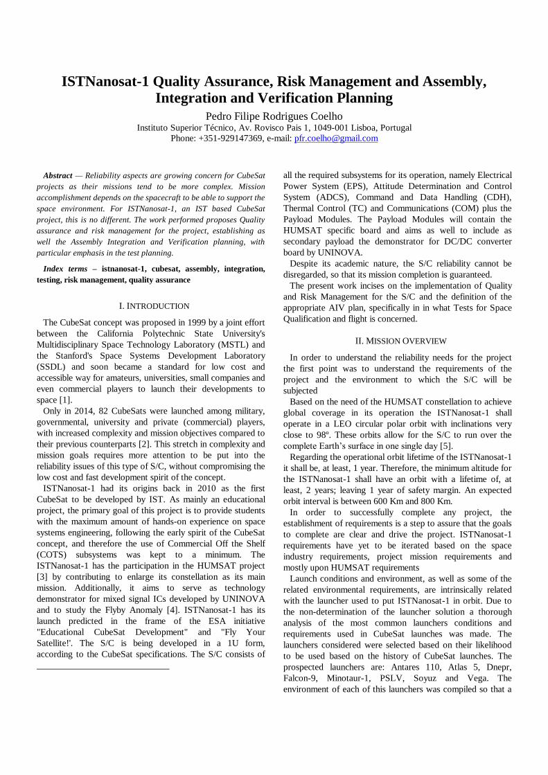
ISTNanosat-1 Quality Assurance, Risk Management and Assembly,
Integration and Verification Planning
Pedro Filipe Rodrigues Coelho Instituto Superior Técnico, Av. Rovisco Pais 1, 1049-001 Lisboa, Portugal
Phone: +351-929147369, e-mail: [email protected]
Abstract1— Reliability aspects are growing concern for CubeSat
projects as their missions tend to be more complex. Mission
accomplishment depends on the spacecraft to be able to support the
space environment. For ISTNanosat-1, an IST based CubeSat
project, this is no different. The work performed proposes Quality
assurance and risk management for the project, establishing as
well the Assembly Integration and Verification planning, with
particular emphasis in the test planning.
Index terms – istnanosat-1, cubesat, assembly, integration,
testing, risk management, quality assurance
I. INTRODUCTION
The CubeSat concept was proposed in 1999 by a joint effort
between the California Polytechnic State University's
Multidisciplinary Space Technology Laboratory (MSTL) and
the Stanford's Space Systems Development Laboratory
(SSDL) and soon became a standard for low cost and
accessible way for amateurs, universities, small companies and
even commercial players to launch their developments to
space [1].
Only in 2014, 82 CubeSats were launched among military,
governmental, university and private (commercial) players,
with increased complexity and mission objectives compared to
their previous counterparts [2]. This stretch in complexity and
mission goals requires more attention to be put into the
reliability issues of this type of S/C, without compromising the
low cost and fast development spirit of the concept.
ISTNanosat-1 had its origins back in 2010 as the first
CubeSat to be developed by IST. As mainly an educational
project, the primary goal of this project is to provide students
with the maximum amount of hands-on experience on space
systems engineering, following the early spirit of the CubeSat
concept, and therefore the use of Commercial Off the Shelf
(COTS) subsystems was kept to a minimum. The
ISTNanosat-1 has the participation in the HUMSAT project
[3] by contributing to enlarge its constellation as its main
mission. Additionally, it aims to serve as technology
demonstrator for mixed signal ICs developed by UNINOVA
and to study the Flyby Anomaly [4]. ISTNanosat-1 has its
launch predicted in the frame of the ESA initiative
"Educational CubeSat Development" and "Fly Your
Satellite!'. The S/C is being developed in a 1U form,
according to the CubeSat specifications. The S/C consists of
all the required subsystems for its operation, namely Electrical
Power System (EPS), Attitude Determination and Control
System (ADCS), Command and Data Handling (CDH),
Thermal Control (TC) and Communications (COM) plus the
Payload Modules. The Payload Modules will contain the
HUMSAT specific board and aims as well to include as
secondary payload the demonstrator for DC/DC converter
board by UNINOVA.
Despite its academic nature, the S/C reliability cannot be
disregarded, so that its mission completion is guaranteed.
The present work incises on the implementation of Quality
and Risk Management for the S/C and the definition of the
appropriate AIV plan, specifically in in what Tests for Space
Qualification and flight is concerned.
II. MISSION OVERVIEW
In order to understand the reliability needs for the project
the first point was to understand the requirements of the
project and the environment to which the S/C will be
subjected
Based on the need of the HUMSAT constellation to achieve
global coverage in its operation the ISTNanosat-1 shall
operate in a LEO circular polar orbit with inclinations very
close to 98º. These orbits allow for the S/C to run over the
complete Earth’s surface in one single day [5].
Regarding the operational orbit lifetime of the ISTNanosat-1
it shall be, at least, 1 year. Therefore, the minimum altitude for
the ISTNanosat-1 shall have an orbit with a lifetime of, at
least, 2 years; leaving 1 year of safety margin. An expected
orbit interval is between 600 Km and 800 Km.
In order to successfully complete any project, the
establishment of requirements is a step to assure that the goals
to complete are clear and drive the project. ISTNanosat-1
requirements have yet to be iterated based on the space
industry requirements, project mission requirements and
mostly upon HUMSAT requirements
Launch conditions and environment, as well as some of the
related environmental requirements, are intrinsically related
with the launcher used to put ISTNanosat-1 in orbit. Due to
the non-determination of the launcher solution a thorough
analysis of the most common launchers conditions and
requirements used in CubeSat launches was made. The
launchers considered were selected based on their likelihood
to be used based on the history of CubeSat launches. The
prospected launchers are: Antares 110, Atlas 5, Dnepr,
Falcon-9, Minotaur-1, PSLV, Soyuz and Vega. The
environment of each of this launchers was compiled so that a
worst case scenario envelope could be later defined for the
test campaign [6][7][8][9][10][11][12][13].
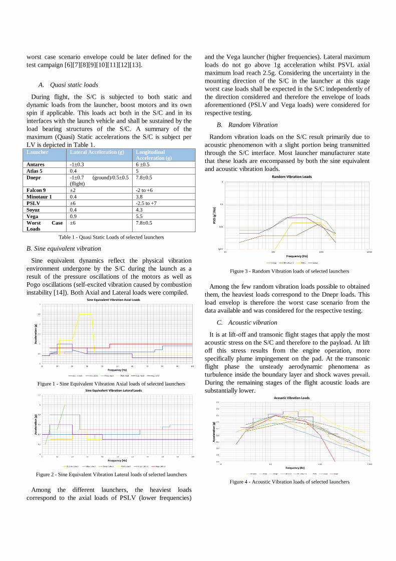
A. Quasi static loads
During flight, the S/C is subjected to both static and
dynamic loads from the launcher, boost motors and its own
spin if applicable. This loads act both in the S/C and in its
interfaces with the launch vehicle and shall be sustained by the
load bearing structures of the S/C. A summary of the
maximum (Quasi) Static accelerations the S/C is subject per
LV is depicted in Table 1. Launcher Lateral Acceleration (g) Longitudinal
Acceleration (g)
Antares -1±0.3 6 ±0.5
Atlas 5 0.4 5
Dnepr -1±0.7 (ground)/0.5±0.5
(flight)
7.8±0.5
Falcon 9 ±2 -2 to +6
Minotaur 1 0.4 3.8
PSLV ±6 -2.5 to +7
Soyuz 0.4 4.3
Vega 0.9 5.5
Worst Case
Loads
±6 7.8±0.5
Table 1 - Quasi Static Loads of selected launchers
B. Sine equivalent vibration
Sine equivalent dynamics reflect the physical vibration
environment undergone by the S/C during the launch as a
result of the pressure oscillations of the motors as well as
Pogo oscillations (self-excited vibration caused by combustion
instability [14]). Both Axial and Lateral loads were compiled.
Figure 1 - Sine Equivalent Vibration Axial loads of selected launchers
Figure 2 - Sine Equivalent Vibration Lateral loads of selected launchers
Among the different launchers, the heaviest loads
correspond to the axial loads of PSLV (lower frequencies)
and the Vega launcher (higher frequencies). Lateral maximum
loads do not go above 1g acceleration whilst PSVL axial
maximum load reach 2.5g. Considering the uncertainty in the
mounting direction of the S/C in the launcher at this stage
worst case loads shall be expected in the S/C independently of
the direction considered and therefore the envelope of loads
aforementioned (PSLV and Vega loads) were considered for
respective testing.
B. Random Vibration
Random vibration loads on the S/C result primarily due to
acoustic phenomenon with a slight portion being transmitted
through the S/C interface. Most launcher manufacturer state
that these loads are encompassed by both the sine equivalent
and acoustic vibration loads.
Figure 3 - Random Vibration loads of selected launchers
Among the few random vibration loads possible to obtained
them, the heaviest loads correspond to the Dnepr loads. This
load envelop is therefore the worst case scenario from the
data available and was considered for the respective testing.
C. Acoustic vibration
It is at lift-off and transonic flight stages that apply the most
acoustic stress on the S/C and therefore to the payload. At lift
off this stress results from the engine operation, more
specifically plume impingement on the pad. At the transonic
flight phase the unsteady aerodynamic phenomena as
turbulence inside the boundary layer and shock waves prevail.
During the remaining stages of the flight acoustic loads are
substantially lower.
Figure 4 - Acoustic Vibration loads of selected launchers
The maximum acoustic loads for the considered launchers
depicted in the figure above corresponds to a composed
envelope of Minotaur-1 (up to 250 Hz) and Dnepr (from
250 Hz onwards loads). Though extremely relevant to larger
S/Cs, vibration loads are typically not directly regarded in
CubeSat projects and the acoustic environment is not tested
directly. This is so because CubeSat are very low volume S/Cs
and the acoustic vibration effects are limited
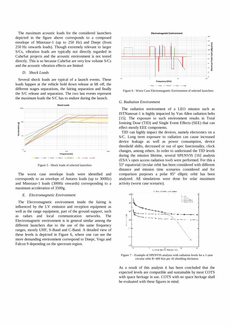
D. Shock Loads
Several shock loads are typical of a launch events. These
loads happen at the vehicle hold down release at lift off, the
different stages separations, the fairing separation and finally
the S/C release and separation. The two last events represent
the maximum loads the S/C has to endure during the launch.
Figure 5 - Shock loads of selected launchers
The worst case envelope loads were identified and
corresponds to an envelope of Antares loads (up to 300Hz)
and Minotaur-1 loads (300Hz onwards) corresponding to a
maximum acceleration of 3500g.
E. Electromagnetic Environment
The Electromagnetic environment inside the fairing is
influenced by the LV emission and reception equipment as
well as the range equipment, part of the ground support, such
as radars and local communication networks. The
Electromagnetic environment is in general similar among the
different launchers due to the use of the same frequency
ranges, mostly UHF, S-Band and C-Band. A detailed view of
these levels is depicted in Figure 6, where one can see the
more demanding environment correspond to Dnepr, Vega and
Falcon 9 depending on the spectrum region.
Figure 6 - Worst Case Electromagnetic Environment of selected launchers
G. Radiation Environment
The radiation environment of a LEO mission such as
ISTNanosat-1 is highly impacted by Van Allen radiation belts
[15]. The exposure to such environment results in Total
Ionizing Dose (TID) and Single Event Effects (SEE) that can
effect mostly EEE components.
TID can highly impact the devices, namely electronics on a
S/C. Long term exposure to radiation can cause increased
device leakage as well as power consumption, device
threshold shifts, decreased or out of spec functionality, clock
changes, among others. In order to understand the TID levels
during the mission lifetime, several SPENVIS [16] analysis
(ESA’s open access radiation tool) were performed. For this a
55º equatorial circular orbit has been considered with different
distance and mission time scenarios considered and for
comparison purposes a polar 85º elliptic orbit has been
analyzed. All simulations were done for solar maximum
activity (worst case scenario).
Figure 7 – Example of SPENVIS analysis with radiation levels for a 1-year
circular orbit R=400 Km per Al shielding thickness
As a result of this analysis it has been concluded that the
expected levels are compatible and sustainable by most COTS
with space heritage in use. COTS with no space heritage shall
be evaluated with these figures in mind.
Mission
time (years)
Orbit Distance
(Km)
TID (rad)(Si) with
1mm Al shielding
1 55 º Circular 400 4x10³
0.33 55º Circular 400 1x10³
1 55º Circular 1000 2x10⁴
0.33 55º Circular 1000 9x10³
1 85º Elliptical Perigee 400
Apogee
1000
1x10⁴
Table 2 - Total Doses for selected orbital scenarios
III. QUALITY ASSURANCE
Upon the definition of baseline of both environment and
project status a project quality assurance plan was
implemented. The extent and detail of such quality assurance
plan can hardly be summarized. Key points of this plan are
therefore highlighted. Naturally based on space industry
standards for larger spacecrafts the depicted plan
contemplated the academic nature of the project and tried to
find a compromise. Configuration and Documentation Control
Management strategies were implemented. In order, the list of
main mission requirements documents was established. To
coordinate this documentation a standardization of
documentation identification was proposed. An example of
the proposed standardization follows:
<Project> - <Subsystem
or Field>
- <Type>
- <Number>
- <Issue>
NS1 - Q - QAP - 01 - A
The documentation storage is constituted by two key
elements: A version storage service and a web based wiki.
The version storage service is the main documentation storage
tool of the project and is to be used mandatorily by all project
intervenient and it must contain all the project information and
documentation. For this purpose, a SVN client has been
implemented. Here working version of the documents,
software, design (mechanical, PCBs, electronics) as well as
final releases have their versions controlled at the different
levels of their development.
Another important point was the establishment on
nonconformance procedures.
Non-conformances refer to a departure from the established
agreements (be it a work product standard, a predefined
procedure, a work product specification, a document plan, an
international standard…) that occur during the development
process of the ISTNanosat-1. Divided among Critical, major
and minor, they have been framed in the context of the
project.
Procurement selection and control strategy was proposed
focusing on control of the critical item identified. Though no
hard requirements for procurement sources are mandatory in
the scope of this project, procedures such as incoming
inspection, EEE component selection process, EEE project
prohibited components as well as materials, mechanical parts
and processes selection procedures were created and
implemented.
Manufacturing, assembly and integration aspects, such as
critical items control, workmanship standards, cleanliness and
contamination control, handling storage and transportation
were defined in detail and the project requirements for this
areas established.
Other safety and reliability consideration were part of the
Quality plan. Risk management was implemented as part of
the project QA plan and details follow.
IV. RISK MANAGEMENT
Risk Management strategies implemented in this project are
mainly based on [17]. The choice of this methodology was
made on trade-off between process implementation
complexity and project benefit. As a first university endeavor
in Space projects and satellite developments, key project
management and quality assurance procedures are to be
implemented alongside with the development of the project
itself. Therefore, a simple yet complete Risk management
system has been chosen. Risk Management shall be
implemented through the effectuation of 3 main steps:
Risk identification
Mitigation techniques
Risk Monitoring
Project risk identification was performed based on the
established procedure.
1. Creation of risk log per subsystem and general risk
register
2. Identification of risks per subsystem/area
3. Name responsible person
4. Rank Likelihood (L) and Consequence (C) of risk
5. Describe rationale for ranking
6. Compute the risk rating with likelihood and
consequence values
7. Average the risk per subsystem to achieve the
mission risks
8. Plot mission risks (subsystem) on L-C Chart
9. Rank and classification of mission risk and subsystem
risk
Upon the identification of the project risk following the
sequence aforementioned, the risk mitigation steps were
implemented. To do so, one of the following mitigation
options was considered:
Risk avoidance by the elimination of the root cause
Control the cause or consequence
Transfer the risk to different person or project
Assume the risk in the project and continue
development
Risk Monitoring was not implemented in the scope of this
work though future work shall consist largely on this task.
Extensive list of the risk identified is depicted in Table 3.
Risks Likeli.
[1-5]
Cons.
[1-5] Mitigation
Inability to find the desired
components 1 2
Components chosen
have at first hand
availability
verification
Mechanical design delays 1 2 TBD

Software design delays 1 2 TBD
Delay due to issues with the
payload provider 1 3
Close contact with
HUMSAT
constellation
responsible is kept
during the
development phase of
the S/C
Delay due to inadequate project
documentation 1 3
Documentation
Management and
requirements
established as part of
this dissertation
according to space
standards
Loss of project information and
documentation 2 3
SVN, wiki and Cloud
drive are implemented
to be used to store all
project data
Loss of project hardware 3 3
Create a project
storage as planned by
the quality
management
procedures
Lack of sufficient training of the
team members performing the
flight qualification tasks.
2 4
Qualification task
shall be performed in
qualified facilities
with either the support
or supervision of local
trained staff
Attrition or turnover of team
members 4 2
A complete
documentation and
configuration
management is to be
put in place as well as
the availability of later
communication with
the leaving staff is to
be guaranteed
Sudden loss of crucial team
members 1 4
Documentation and
configuration
management
COTS components prices increase 4 1
Create buffer budget
for unpredictable
situations
Inability to obtain funding 1 5 TBD
Delay of receiving promised
funding 1 2
Funding based is
allocated via academic
funds
Launch opportunity cannot be
guaranteed 2 5
Project is part of the
ESA
Flight you satellite
initiative
Deviation from desired orbit upon
launched 1 4
Aim for reliable
launch providers,
namely ESA through
the Fly your Satellite
Program.
Software interface issues between
payload and spacecraft bus 2 4
Thorough software
Testing
Hardware/electrical interface issues
between payload and spacecraft bus 1 4
Thorough Testing and
Qualification
Payload malfunction due to
electronic issues 1 4
Main Payload with
space heritage.
PFM testing
No frequency on which to
communicate with spacecraft due to
delay in receiving frequency
allocation
1 2
Allocation of the
COM band to be
performed as soon as
possible
Failure of spacecraft radios 2 5 Test and qualification
Failure of spacecraft antennas due
to improper deployment or
activation
1 4
Deployment test and
simplicity in the
deployment
mechanisms design
must be implemented
Failure of ground station 1 2
Established ground
station with large
background and
adequate facilities is
available
Failure of flight computer 4 2
Redundant
components and
connection have been
implemented and
operation of the S/C is
guaranteed. No single
point of failure
Failure of sensors 4 2
Redundant
components
implemented
Failure of actuators causing
unstable spacecraft motion (due to
either hardware or software issues)
1 4 TBD
Failure of power regulation/battery
system 2 5
EPS design measures
implemented.
Failure of solar panels to generate
power 1 4
Power budget margin
implementation. Full
coverage of the S/C
with Solar panels
increasing the number
and therefore
redundancy
Unexpected thermal environment 2 2
Worst case scenario
Qualification test
campaign
Unexpected vibration environment 2 2
Worst case scenario
Qualification test
campaign
Spacecraft will not deorbit within
25 years after end-of-life 1 1
Aim for reliable
launch providers, that
can guarantee
deployment at low
orbits
Spacecraft does not meet
requirements (i.e. dimension, mass
limits, structural/thermal analyses)
3 4
Complete definition of
mission requirements
and Project control
over the known
requirements
Selected key component with no
known space heritage do not
survive test conditions
3 3
Alternatives must be
identified in the
design phase and
components without
space heritage shall be
selected based on their
range of operation
Table 3 – Summarized Project Risk Register
V. AIV PLAN
The AIV Plan implemented tackled assembly and integration
high level aspects but it focused mainly in the verification
aspects, more specifically in the testing of the ISTNanosat-1.
Integration and assembly aspects of the ISTNanosat-1 could
not be assessed in detail due to the status of development of
the project. At a high level, the Integration procedure of the
S/C, independently of the model, must guarantee the interface
connection and the proper operation at integrated subsystems
and S/C level.
For testing high level definition, the model approach was
developed to better suit the project needs.
The model approach considered more suitable for the
ISTNanosat-1 development and verification, due to its inherit
flexibility and good compromise between costs and reliability
validation was and hybrid approach. Such hybrid approach
guarantees implies the Qualification of the S/C and the later
use of Protoflight units as the flying models.
The adopted philosophy resulted in the implementation of 4
model levels:
1. Development Models (DM) – subsystems level
2. Engineering Mechanical Model (EM) – S/C level
3. Engineering Qualification Model (EQM) – S/C level
4. Protoflight Model (PFM) – S/C level
Development Models – These shall be composed by the
development boards constituting each of the S/C subsystems.
Engineering Mechanical Model – Shall be a representative
model of the fundamental structural elements of the S/C.
Mechanical dummies of the Subsystems shall be used and the
Model tested for mechanical stress.
Engineering Qualification Model – Complete and functional
model of the S/C that is fully representative of the
components and manufacturing processes to be used in the
flight model.
Protoflight Model – Flight Model based on the Engineering
Qualification Model. Same manufacturing processes and
components must be used.
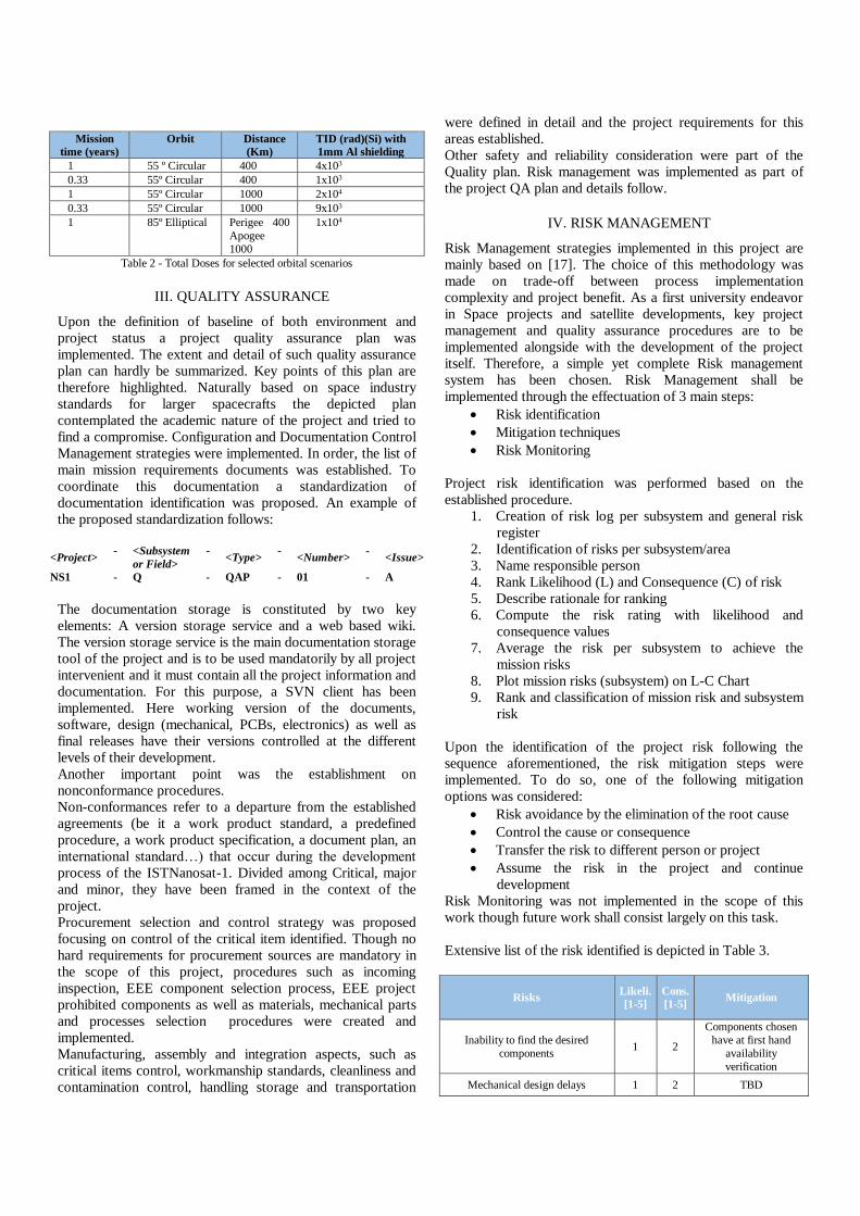
The approach selected for the ISTNanosat-1 aims to assess
reliability and functionality has early as possible in the
development process. In that sense, development models (i.e.
each subsystem) are to be bench tested and tested making use
of atmospheric balloons, namely the BALUA platform, for
functionality. Mechanical models shall be tested for
qualification level mechanical loads to guarantee the integrity
of the elements bearing the major mechanical loads before
these tests are applied in the costlier EQM. EQM model shall
undergo the full qualification test campaign (Figure 9 refers)
to guarantee the compliance of the S/C engineered. EQM
model shall be kept after testing and its parts used for spare
parts for the PFM. PFM shall undergo the acceptance test
campaign prior to flight (Figure 8 refers).
Figure 8 – Acceptance test flow
Figure 9 – Qualification test flow
As testing is concerned Mechanical Ground Support
Equipment (MGSE) and Electrical Ground Support
Equipment (EGSE) shall be implemented in the frame of the
project and high level architectures for these were proposed
as primordial and mandatory condition the MGSE/EGSE and
any other support system shall not interfere in any way in the
outcome of the tests to space qualify the S/C, being in
particular immune to the test conditions and compliant with
safety requirements.
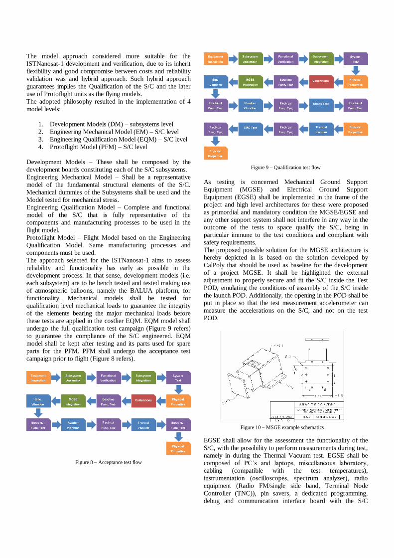
The proposed possible solution for the MGSE architecture is
hereby depicted in is based on the solution developed by
CalPoly that should be used as baseline for the development
of a project MGSE. It shall be highlighted the external
adjustment to properly secure and fit the S/C inside the Test
POD, emulating the conditions of assembly of the S/C inside
the launch POD. Additionally, the opening in the POD shall be
put in place so that the test measurement accelerometer can
measure the accelerations on the S/C, and not on the test
POD.
Figure 10 – MSGE example schematics
EGSE shall allow for the assessment the functionality of the
S/C, with the possibility to perform measurements during test,
namely in during the Thermal Vacuum test. EGSE shall be
composed of PC’s and laptops, miscellaneous laboratory,
cabling (compatible with the test temperatures),
instrumentation (oscilloscopes, spectrum analyzer), radio
equipment (Radio FM/single side band, Terminal Node
Controller (TNC)), pin savers, a dedicated programming,
debug and communication interface board with the S/C

equipment. A 2 segment architecture is depicted. It
encompasses a Remote segment to acquire the
communications made by the S/C, to instruct and send
commands remotely to the S/C (these two segments together
are comparable to the Ground Station) and a Command and
Test segment to directly interface and diagnose all the
different and available interface points of the S/C, particularly
built to endure the test conditions. This architecture is
depicted Figure 11.
Figure 11 - EGSE High Level Architecture
V. TEST PLAN
As result of the analysis of the S/C performed, environment
and the standard requirements for CubeSat, an appropriate
test plan was proposed for qualification and space flight. The
test plan considers worst case scenarios and qualifies the s/c
to flight in most of the CubeSat typical launchers. As detailed
per the qualification and acceptance test flow the sequence of
these tests was previously defined and the details on the tests
to be executed and respective conditions follow:
A. Physical Properties Test
Physical properties are key for CubeSat to be compliant with
the use in P-PODS or similar. The physical properties that
need to be teste are mass, dimensions and center of gravity.
Requirements follow:
Mass: The maximum mass of a 1U CubeSat shall be 1.33 kg.
Dimensions: 100x100x100 mm.
Center of Gravity with respect to geometric Center: The
1U CubeSat center of gravity shall be located within 4.5 cm
from its geometric center in the Z direction (S/C longest
dimension).
A. Sine Equivalent Vibration Test
Sine Vibration Qualification Requirement are based on ECSS-
Q-ST-10-03.
Load levels are defined as KQ x Limit Load Spectrum sweep
with 2 Oct/min duration and ranging from 0 Hz to 100 Hz.
The qualification factor KQ is given in ECSS‐E‐ST‐32‐10
clause 4.3.1 and KQ=1.25. Limit Load Spectrum is
considered as the worst case envelop from the launch
environment depicted in Figure 1 and Figure 2. Since Axial
loads envelope is of greater value then Lateral loads those are
considered as baseline values for the Qualification test levels.
Qualification Model Level Protoflight Model Level
Duration Sweep at 2 Oct/min, 5 Hz –
100 Hz
Sweep at 4 Oct/min, 5 Hz –
100 Hz
Load (KQ = 1.25 x Limit Load
Spectrum)
(KQ = 1.25 x Limit Load
Spectrum)
Tolerances Frequency: ± 2 % (or ±1 Hz whichever is greater)
Amplitude: ± 10 %
Sweep rate (Oct/min): ± 5 %
Number of
applications
1 on each of 3 orthogonal axes
Table 4 – Sine Vibration test condition
Frequency (HZ) 5 5 10 10 100
Acceleration 0.5 1.0 1.0 3.75 3.75
Table 5 – Sine Vibration Load
Figure 12 - Random Vibration Qualification Test Level
A. Random Vibration Test
Random Vibration Qualification Requirement are based on
ECSS-Q-ST-10-03.
Load levels are defined as Maximum spectrum expected + 3
dB on PSD Values. Limit Load Spectrum is considered as the
worst case envelop from the launch environment depicted in
Figure 3. Many of the highlighted launchers had their random
vibration environment not depicted or defined by acoustics,
which is of most relevance for large payloads and not
CubeSats. Therefore, it was considered of relevance to further
enhance the load requirements to the NASA GEVS
requirements for systems with mass below 25 Kg. Both worst
case envelope related qualification level and GEVS are
depicted in Figure 13
Qualification Model Level Protoflight Model Level
Duration 2 minutes 1 minute
Load Maximum spectrum expected
+ 3 dB on PSD
Maximum spectrum
expected + 3 dB on PSD
Tolerances Amplitude (PSD, frequency resolution better than 10Hz): 20
Hz ‐ 1000 Hz ‐1 dB / +3 dB; 1000 Hz ‐ 2000 Hz ± 3 dB
Random overall g r.m.s. ± 10 %
Number of
applications
1 on each of 3 orthogonal axes
Table 6 – Random Vibration test conditions
Frequency (Hz) 20 50 800 2000
PSD (g2/Hz) 0.026 0.16 0.16 0.026
G (RMS) 14.2
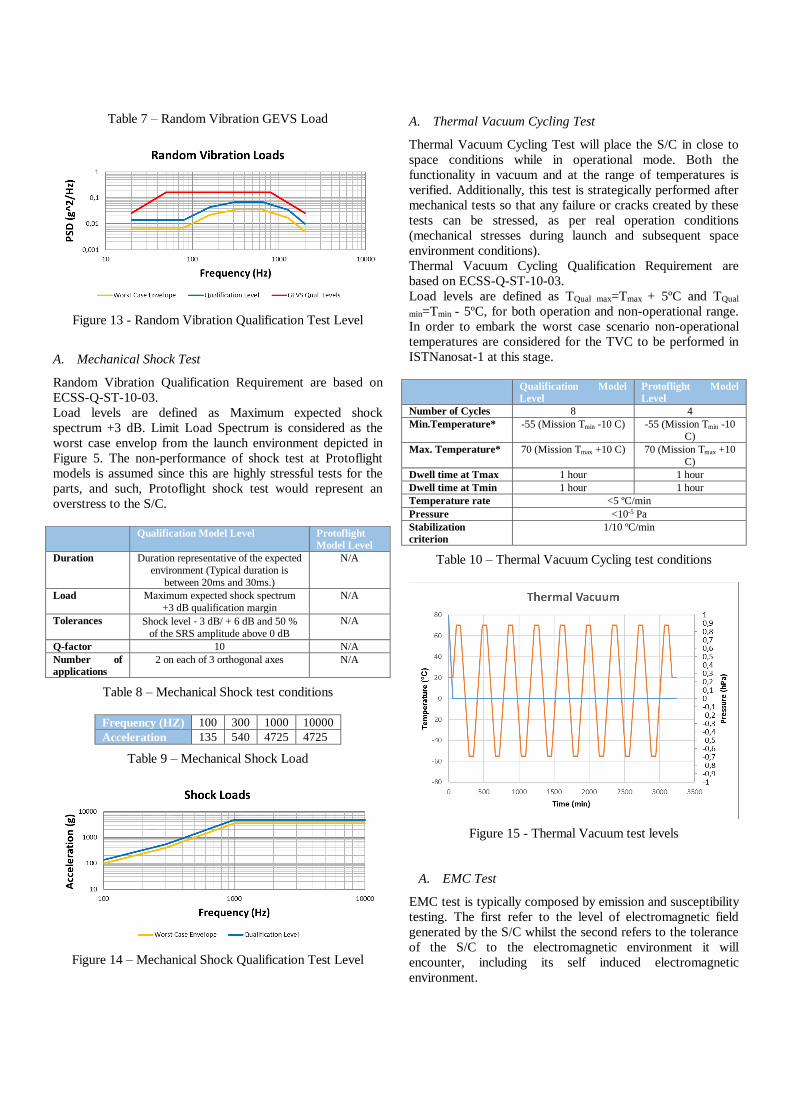
Table 7 – Random Vibration GEVS Load
Figure 13 - Random Vibration Qualification Test Level
A. Mechanical Shock Test
Random Vibration Qualification Requirement are based on
ECSS-Q-ST-10-03.
Load levels are defined as Maximum expected shock
spectrum +3 dB. Limit Load Spectrum is considered as the
worst case envelop from the launch environment depicted in
Figure 5. The non-performance of shock test at Protoflight
models is assumed since this are highly stressful tests for the
parts, and such, Protoflight shock test would represent an
overstress to the S/C.
Qualification Model Level Protoflight
Model Level
Duration Duration representative of the expected
environment (Typical duration is
between 20ms and 30ms.)
N/A
Load Maximum expected shock spectrum
+3 dB qualification margin
N/A
Tolerances Shock level ‐ 3 dB/ + 6 dB and 50 %
of the SRS amplitude above 0 dB
N/A
Q-factor 10 N/A
Number of
applications
2 on each of 3 orthogonal axes N/A
Table 8 – Mechanical Shock test conditions
Frequency (HZ) 100 300 1000 10000
Acceleration 135 540 4725 4725
Table 9 – Mechanical Shock Load
Figure 14 – Mechanical Shock Qualification Test Level
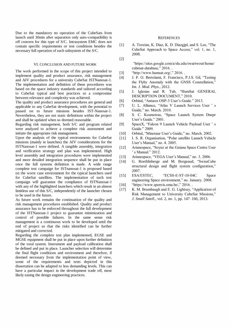
A. Thermal Vacuum Cycling Test
Thermal Vacuum Cycling Test will place the S/C in close to
space conditions while in operational mode. Both the
functionality in vacuum and at the range of temperatures is
verified. Additionally, this test is strategically performed after
mechanical tests so that any failure or cracks created by these
tests can be stressed, as per real operation conditions
(mechanical stresses during launch and subsequent space
environment conditions).
Thermal Vacuum Cycling Qualification Requirement are
based on ECSS-Q-ST-10-03.
Load levels are defined as TQual max=Tmax + 5ºC and TQual
min=Tmin - 5ºC, for both operation and non-operational range.
In order to embark the worst case scenario non-operational
temperatures are considered for the TVC to be performed in
ISTNanosat-1 at this stage.
Qualification Model
Level
Protoflight Model
Level
Number of Cycles 8 4
Min.Temperature* -55 (Mission Tmin -10 C) -55 (Mission Tmin -10
C)
Max. Temperature* 70 (Mission Tmax +10 C) 70 (Mission Tmax +10
C)
Dwell time at Tmax 1 hour 1 hour
Dwell time at Tmin 1 hour 1 hour
Temperature rate <5 ºC/min
Pressure <10-5 Pa
Stabilization
criterion
1/10 ºC/min
Table 10 – Thermal Vacuum Cycling test conditions
Figure 15 - Thermal Vacuum test levels
A. EMC Test
EMC test is typically composed by emission and susceptibility
testing. The first refer to the level of electromagnetic field
generated by the S/C whilst the second refers to the tolerance
of the S/C to the electromagnetic environment it will
encounter, including its self induced electromagnetic
environment.
Due to the mandatory no operation of the CubeSats from
launch until 30min after separation only auto-compatibility is
off concern for this type of S/C. Intrasystem EMC does not
contain specific requirements or test conditions besides the
necessary full operation of each subsystem of the S/C.
VI. CONCLUSION AND FUTURE WORK
The work performed in the scope of this project intended to
implement quality and product assurance, risk management
and AIV procedures for a university CubeSat ISTNanosat-1.
The implementation and definition of these procedures was
based on the space industry standards and tailored according
to CubeSat typical and best practices so a compromise
between relevance and complexity was achieved.
The quality and product assurance procedures are general and
applicable to any CubeSat development, with the potential to
passed on to future missions besides IST-Nanosat-1.
Nevertheless, they are not static definitions within the project
and shall be updated when so deemed reasonable.
Regarding risk management, both S/C and program related
were analyzed to achieve a complete risk assessment and
initiate the appropriate risk management.
Upon the analysis of the typical environments for CubeSat
missions (mainly in launches) the AIV considerations for the
ISTNanosat-1 were defined. A tangible assembly, integration
and verification strategy and plan was implemented. High
level assembly and integration procedures were implemented
and more detailed integration sequence shall be put in place
once the full systems definition is made. A wide range
complete test campaign for ISTnanosat-1 is proposed based
on the worst case environment for the typical launchers used
for CubeSat satellites. The implementation of such test
campaign will guarantee the compliance of ISTNanosat-1
with any of the highlighted launchers which result in an almost
limitless use of this S/C, independently of the launcher chosen
to be used in the future.
As future work remains the continuation of the quality and
risk management procedures established. Quality and product
assurance has to be enforced throughout the full development
of the ISTNanosat-1 project to guarantee minimization and
control of possible failures. In the same sense risk
management is a continuous work to be developed until the
end of project so that the risks identified can be further
mitigated and corrected.
Regarding the complete test plan implemented, EGSE and
MGSE equipment shall be put in place upon further definition
of the total system. Instrument and payload calibration shall
be defined and put in place. Launcher selection will determine
the final flight conditions and environment and therefore, if
deemed necessary from the implementation point of view,
some of the requirements and tests depicted in this
dissertation can be adapted to less demanding levels. This can
have a particular impact in the development trade off, most
likely easing the design engineering practices.
REFERENCES
[1] A. Toorian, K. Diaz, K. D. Diazgjpl, and S. Lee, “The
CubeSat Approach to Space Access,” vol. 1, no. 1,
2008.
[2]
“https://sites.google.com/a/slu.edu/swartwout/home/
cubesat-database,” 2016. .
[3] “http://www.humsat.org/,” 2016. .
[4] J. P. O. Bertolami, F. Francisco, P.J.S. Gil, “Testing
the Flyby Anomaly with the GNSS Constellation,”
Int. J. Mod. Phys., 2012.
[5] J. Iglesias and R. Tub, “HumSat GENERAL
DESCRIPTION DOCUMENT,” 2010.
[6] Orbital, “Antares OSP-3 User’s Guide.” 2013.
[7] U. L. Alliance, “Atlas V Launch Services User ’ s
Guide,” no. March. 2010.
[8] S. C. Kosmotras, “Space Launch System Dnepr
User’s Guide.” 2001.
[9] SpaceX, “Falcon 9 Launch Vehicle Payload User ’ s
Guide.” 2009.
[10] Orbital, “Minotaur User’s Guide,” no. March. 2002.
[11] I. S. R. Organisation, “Polar satellite Launch Vehicle
User’s Manual,” no. 4. 2005.
[12] Arianespace, “Soyuz at the Guiana Space Centre User
’ s Manual.” 2012.
[13] Arianespace, “VEGA User’s Manual,” no. 3. 2006.
[14] G. Roethlisberge and M. Borgeaud, “SwissCube
structural design and flight system configuration,”
2007.
[15] ESA/ESTEC, “ECSS-E-ST-10-04C Space
engineering Space environment,” no. January. 2008.
[16] “https://www.spenvis.oma.be/,” 2016. .
[17] K. M. Brumbaugh and E. G. Lightsey, “Application of
Risk Management to University CubeSat Missions,”
J. Small Satell., vol. 2, no. 1, pp. 147–160, 2013.