Embed Size (px)
Citation preview
INSTRUCTION MANUAL
ACTIVE AQUA SUBMERSIBLE PUMP
Active Aqua Pumps from Hydrofarm are carefully inspected and tested to ensure both safety and operating performance. However, failure to follow the instructions and warnings in this manual may result in pump damage and/or serious injury. Be sure to read and save this manual for future reference.
LIMITED WARRANTY
Your Active Aqua Pump is guaranteed to work for one year from the date of retail purchase. Replaceable filter material not included. Save your retail receipt/invoice, a copy is required for all warranty work.
Any alterations to a pump or cord will void warranty. Contact the place of purchase for repair or replacement. Active Aqua Pumps are sold and serviced only through dealers.
FOR MODELS: AAPW40, AAPW160, AAPW250, AAPW400, AAPW550, AAPW800, AAPW1000
AAPW250/400
AAPW800/550
AAPW1000AAPW160
AAPW40
AASubPump_Instr.11
SYMPTOM CAUSE SOLUTION
The pump does not run Power is not turned on
Incorrectly plugged in
Bound impeller
Turn on the power
Plug in correctly
Remove foreign matter from impeller
The motor repeats ON/OFF without running pump. It stops and does not restart
Wrong voltage
The water intake or outlet pipe is clogged with foreign matter
Correct voltage
Clean out the intake and outlet
The pump runs with reduced or no performance
Wrong frequency
Impeller worn out
Low water level
Correct frequency
Replace impeller
Ensure the pump is fully submerged
The pump runs normally at the beginning but the water flows sluggishly or there is no water
Hose is too long or clogged
Air in the impeller chamber
Shorten hose and/or clean out
To get rid of air, put pump into the water. Turn the switch to “ON” and “OFF” intermittently to clear air from pump
TROUBLESHOOTING GUIDE
www.hydrofarm.com
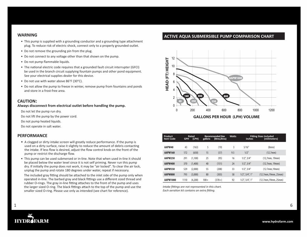
AAPW40 43 (163) 5 (19) 3 5/16" (8mm)
AAPW160 172 (650) 15 (57) 9.5 1/2" (12.7mm)
AAPW250 291 (1,100) 25 (95) 16 1/2", 3/4" (12,7mm, 19mm)
AAPW400 370 (1,400) 40 (151) 24 1/2", 3/4" (12.7mm, 19mm)
AAPW550 529 (2,000) 55 (208) 33 1/2", 3/4" (12.7mm,19mm)
AAPW800 793 (3,000) 80 (303) 58 1/2", 3/4", 1" (12.7mm,19mm, 25mm)
AAPW1000 1110 (4,200) 100+ (378+) 92 1/2", 3/4", 1" (12.7mm,19mm, 25mm)
WARNING• This pump is supplied with a grounding conductor and a grounding type attachment
plug. To reduce risk of electric shock, connect only to a properly grounded outlet.• Do not remove the grounding pin from the plug.• Do not connect to any voltage other than that shown on the pump.• Do not pump flammable liquids.• The national electric code requires that a grounded fault circuit interrupter (GFCI)
be used in the branch circuit supplying fountain pumps and other pond equipment. See your electrical supplies dealer for this device.
• Do not use with water above 86°F (30°C).• Do not allow the pump to freeze in winter, remove pump from fountains and ponds
and store in a frost-free area.
CAUTION: Always disconnect from electrical outlet before handling the pump.
Do not let the pump run dry.Do not lift the pump by the power cord.Do not pump heated liquids.Do not operate in salt water.
PERFORMANCE• A clogged or dirty intake screen will greatly reduce performance. If the pump is
used on a dirty surface, raise it slightly to reduce the amount of debris contacting the intake. If less flow is desired, adjust the flow control knob on the front of the pump or restrict the discharge flow.
• This pump can be used submersed or in-line. Note that when used in-line it should be placed below the water level since it is not self priming. Never run this pump dry. If initially the pump does not work, it may be “air locked”. To clear the air lock, unplug the pump and rotate 180 degrees under water, repeat if necessary.
The included gray fitting should be attached to the inlet side of the pump only when operated in-line. The barbed gray and black fittings use a different sized thread and rubber O-rings. The gray in-line fitting attaches to the front of the pump and uses the larger sized O-ring. The black fittings attach to the top of the pump and use the smaller sized O-ring. Please use only as intended (see chart for reference).
Product Item Code
Rated GPH (LPH)
Recommended Size gallons (litres,litros)
Watts Fitting Sizes Included inches (milimeters)
0
2
4
6
8
10
12
0 200 400 600 800 1000 1200
HEA
D (F
T) H
EIG
HT
GALLONS PER HOUR (LPH) VOLUME
AAPW1000
800
550
160
40
400
Pump Gallons RecommendedModel Per Hour Reservoir SizeAAPW1000 1110 100+ GallonAAPW800 793 80 GallonAAPW550 529 55 GallonAAPW400 370 40 GallonAAPW250 291 25 GallonAAPW160 171 15 GallonAAPW40 43 5 Gallon
Active Air Submersible Pump Comparison Chart
250
ACTIVE AQUA SUBMERSIBLE PUMP COMPARISON CHART
Intake fittings are not represented in this chart. Each aeration kit contains an extra fitting.
61
www.hydrofarm.com
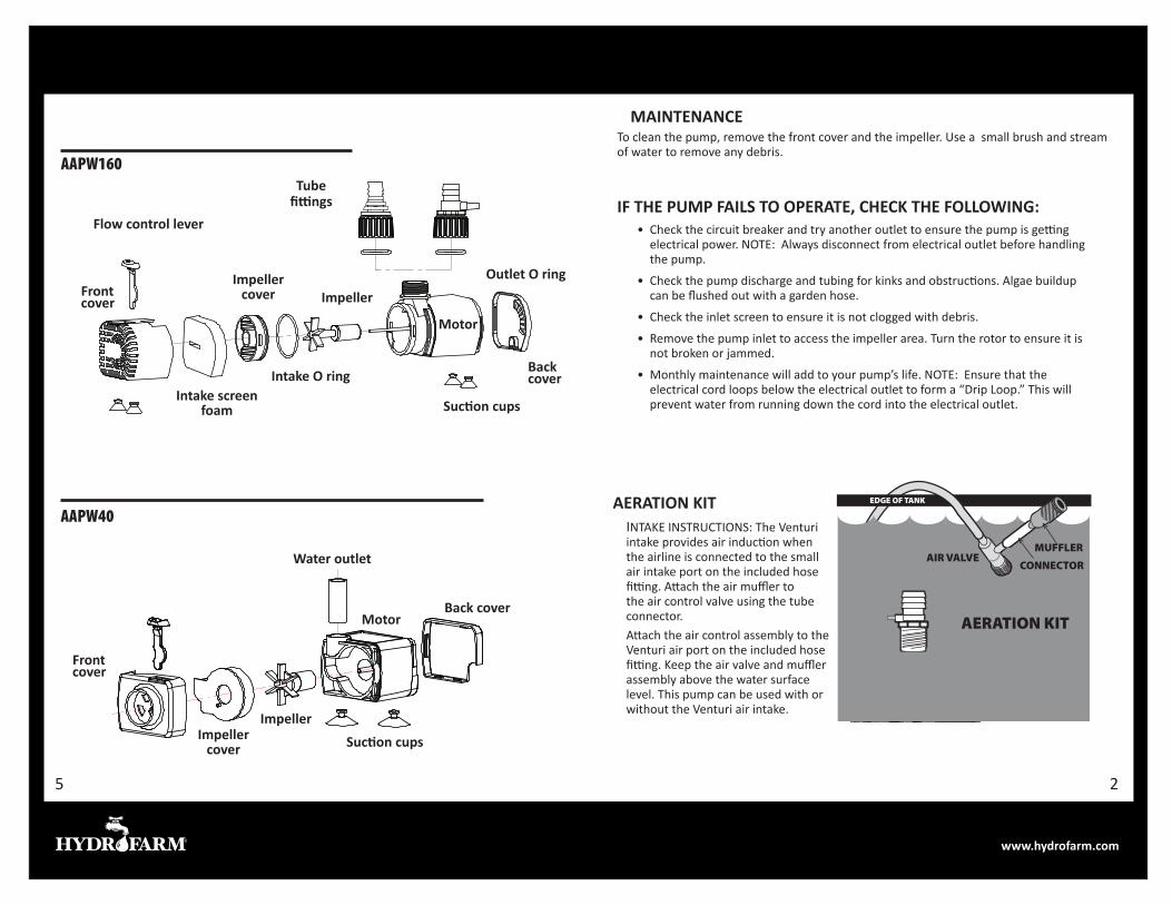
MAINTENANCE To clean the pump, remove the front cover and the impeller. Use a small brush and stream of water to remove any debris.
IF THE PUMP FAILS TO OPERATE, CHECK THE FOLLOWING:• Check the circuit breaker and try another outlet to ensure the pump is getting
electrical power. NOTE: Always disconnect from electrical outlet before handling the pump.
• Check the pump discharge and tubing for kinks and obstructions. Algae buildup can be flushed out with a garden hose.
• Check the inlet screen to ensure it is not clogged with debris.
• Remove the pump inlet to access the impeller area. Turn the rotor to ensure it is not broken or jammed.
• Monthly maintenance will add to your pump’s life. NOTE: Ensure that the electrical cord loops below the electrical outlet to form a “Drip Loop.” This will prevent water from running down the cord into the electrical outlet.
AAPW160
Outlet O ringC M Y CM
MY
CY
CMY K
AAPW160–EXILUUS.pdf 1 2/17/12 9:23 AM
Suction cups
Suction cups
Back cover
Impeller cover
Impeller cover
Impeller
Motor
Motor
Intake O ring
Front cover
Front cover
Intake screen foam
Flow control lever
AAPW40
Water outlet
Impeller
Back cover
Tube fittings
EDGE OF TANK
MUFFLER
CONNECTORAIR VALVE
AERATION KIT
AERATION KITINTAKE INSTRUCTIONS: The Venturi intake provides air induction when the airline is connected to the small air intake port on the included hose fitting. Attach the air muffler to the air control valve using the tube connector.Attach the air control assembly to the Venturi air port on the included hose fitting. Keep the air valve and muffler assembly above the water surface level. This pump can be used with or without the Venturi air intake.
25
www.hydrofarm.com
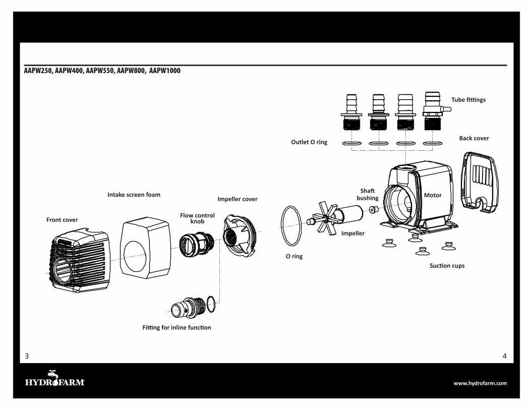
O ring
Impeller
Suction cups
Outlet O ring Back cover
Motor
Tube fittings
Shaft bushing
Front cover
Intake screen foam
AAPW250, AAPW400, AAPW550, AAPW800, AAPW1000
Fitting for inline function
Flow control knob
Impeller cover
43