Embed Size (px)
Citation preview
Malaysian Journal of Civil Engineering 21(2) : 152-167 (2009)
SHEAR STRENGTHENING OF R/C BEAMS USING
AFRP STIRRUPS WITH ANCHORED ENDS
Iswandi Imran1 and Mujiman
2
1Fac. of Civil and Env. Eng., Institut Teknologi Bandung, Bandung 40132, Indonesia.
2Dept of Civil Eng., Politeknik Bandung, Ciwaruga, Bandung, Indonesia.
*Corresponding Author: [email protected]
Abstract: Many studies have been conducted on the behaviour of reinforced concrete (R/C)
beams shear-strengthened with fiber reinforced polymer (FRP) sheets. The studies show that
FRP materials can produce good performance when used to carry some portions of shear force in
the shear-strengthened beam. However, the performance of the FRP sheets used for shear
strengthening is found limited by bond capacity between the FRP sheets and concrete surface. To
improve the bond performance, an anchorage system can be introduced to the FRP strengthening
scheme. This paper presents experimental and analytical studies conducted to evaluate the
contribution and behaviour of aramid fiber reinforced polymer (AFRP) sheets with anchored
ends in carrying the shear force in reinforced concrete beams. In the study, nine reinforced
concrete beam specimens were fabricated and tested. Test parameters of the study include
thickness of AFRP sheet used, type of wraps applied, type of anchors and diameter of anchor
head used. Two types of anchorage system were proposed in the study, i.e. insert anchor system
and C-embedded anchor system. The results from this study showed that the proposed anchorage
system can improve the contribution of the FRP sheets in carrying the shear force in beams. In
addition, the C-embedded anchor system exhibits better performance than the insert anchor
system. Lastly, the behaviour of beams strengthened using FRP stirrups with anchored ends can
be closely predicted by the ACI 440 design equations applicable for full-wrap scheme.
Keywords: Fiber Reinforced Polymer (FRP) sheets; Shear strengthening; Bond capacity; C-
embedded anchor; Insert anchor.
1.0 Introduction
The changes in building functions, the revisions of the existing building codes or
the increase in safety requirements are amongst the factors that may cause the
need for structural strengthening in buildings. Types of strengthening methods
that are commonly applied to reinforced concrete structures are concrete-
jacketing, steel-jacketing, and external post-tensioning. Since the last decade,
there is another type of concrete strengthening method that starts gaining
Malaysian Journal of Civil Engineering 21(2) : 152-167 (2009) 153
popularity in the construction industry, i.e. FRP sheet-jacketing. This type of
strengthening method uses FRP (Fiber Reinforced Polymer) sheets, made of
glass (G), carbon (C) or aramid (A) fibers. The fibers in the FRP sheets have
high tensile strength and therefore, they can be used to replace steel
reinforcement in reinforced concrete members.
The resistance of structural elements that can be improved with the use of
FRP sheets includes shear, flexural, torsion and axial resistance (ACI 440 2002).
The strengthening method with the FRP sheet-jacketing is basically done by
wrapping or attaching the FRP sheets on concrete surface using epoxy-based
glue. Shear strengthening of concrete beams can be done through wrapping the
FRP sheets around the beam sections, with the shape resembling stirrup
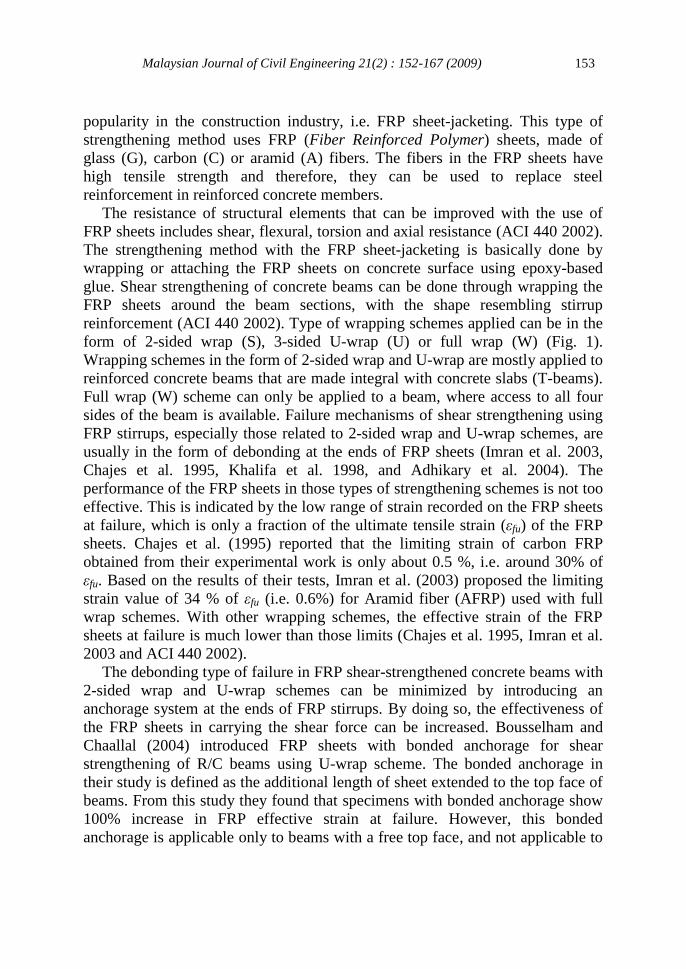
reinforcement (ACI 440 2002). Type of wrapping schemes applied can be in the
form of 2-sided wrap (S), 3-sided U-wrap (U) or full wrap (W) (Fig. 1).
Wrapping schemes in the form of 2-sided wrap and U-wrap are mostly applied to
reinforced concrete beams that are made integral with concrete slabs (T-beams).
Full wrap (W) scheme can only be applied to a beam, where access to all four
sides of the beam is available. Failure mechanisms of shear strengthening using
FRP stirrups, especially those related to 2-sided wrap and U-wrap schemes, are
usually in the form of debonding at the ends of FRP sheets (Imran et al. 2003,
Chajes et al. 1995, Khalifa et al. 1998, and Adhikary et al. 2004). The
performance of the FRP sheets in those types of strengthening schemes is not too
effective. This is indicated by the low range of strain recorded on the FRP sheets
at failure, which is only a fraction of the ultimate tensile strain (εfu) of the FRP
sheets. Chajes et al. (1995) reported that the limiting strain of carbon FRP
obtained from their experimental work is only about 0.5 %, i.e. around 30% of
εfu. Based on the results of their tests, Imran et al. (2003) proposed the limiting
strain value of 34 % of εfu (i.e. 0.6%) for Aramid fiber (AFRP) used with full
wrap schemes. With other wrapping schemes, the effective strain of the FRP
sheets at failure is much lower than those limits (Chajes et al. 1995, Imran et al.
2003 and ACI 440 2002).
The debonding type of failure in FRP shear-strengthened concrete beams with
2-sided wrap and U-wrap schemes can be minimized by introducing an
anchorage system at the ends of FRP stirrups. By doing so, the effectiveness of
the FRP sheets in carrying the shear force can be increased. Bousselham and
Chaallal (2004) introduced FRP sheets with bonded anchorage for shear
strengthening of R/C beams using U-wrap scheme. The bonded anchorage in
their study is defined as the additional length of sheet extended to the top face of
beams. From this study they found that specimens with bonded anchorage show
100% increase in FRP effective strain at failure. However, this bonded
anchorage is applicable only to beams with a free top face, and not applicable to
Malaysian Journal of Civil Engineering 21(2) : 152-167 (2009) 154
beams with monolithic slabs or T-beams. So, this type of strengthening scheme
can not be applied to most beams in R/C buildings.
a) U-wrap (U) b) 2-Sided wrap (S) c) Full wrap (W)
Figure 1: Wrapping schemes for shear strengthening
Researches carried out to study the performance of shear strengthened R/C
beams using FRP stirrups with other types of anchorage systems are still limited.
A design guideline for this kind of shear strengthening is also not available at
present. This paper presents the development of anchorage systems used to
increase the effectiveness of FRP stirrups with U-wrap or 2-sided wrap schemes
in carrying shear force in R/C beams. Two types of anchorage systems are
proposed in the study, i.e. insert anchor system and C-embedded anchor system.
An experimental study has been carried out by the authors to evaluate the
effectiveness of the shear strengthened R/C beams using FRP stirrups with this
kind of anchorage systems.
2.0 Experimental Program
2.1 Test Parameters and Details of Beam Specimens
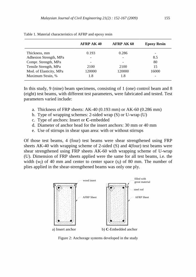
Type of FRP sheets used in this study is AFRP (Aramid Fiber Reinforced
Polymer), which is the product of PT. Fosroc Indonesia, with the brand name of
Renderoc FR10. The epoxy resin used to glue the FRP sheets on concrete
surfaces was Nitobond EP10. The characteristics of Renderoc FR10 and
Nitobond EP10 can be seen in Table 1.
FRP Sheet FRP Sheet
Malaysian Journal of Civil Engineering 21(2) : 152-167 (2009) 155
wood insert
AFRP Sheet AFRP Sheet
filled with
grout material
steel rod
Table 1. Material characteristics of AFRP and epoxy resin
AFRP AK 40 AFRP AK 60 Epoxy Resin
Thickness, mm 0.193 0.286 -
Adhesion Strength, MPa - - 8.5
Compr. Strength, MPa - - 80
Tensile Strength, MPa 2100 2100 15
Mod. of Elasticity, MPa 120000 120000 16000
Maximum Strain, % 1.8 1.8 -
In this study, 9 (nine) beam specimens, consisting of 1 (one) control beam and 8
(eight) test beams, with different test parameters, were fabricated and tested. Test
parameters varied include:
a. Thickness of FRP sheets: AK-40 (0.193 mm) or AK-60 (0.286 mm)
b. Type of wrapping schemes: 2-sided wrap (S) or U-wrap (U)
c. Type of anchors: Insert or C-embedded
d. Diameter of anchor head for the insert anchors: 30 mm or 40 mm
e. Use of stirrups in shear span area: with or without stirrups
Of those test beams, 4 (four) test beams were shear strengthened using FRP
sheets AK-40 with wrapping scheme of 2-sided (S) and 4(four) test beams were
shear strengthened using FRP sheets AK-60 with wrapping scheme of U-wrap
(U). Dimension of FRP sheets applied were the same for all test beams, i.e. the
width (wf) of 40 mm and center to center space (sf) of 80 mm. The number of
plies applied in the shear-strengthened beams was only one ply.
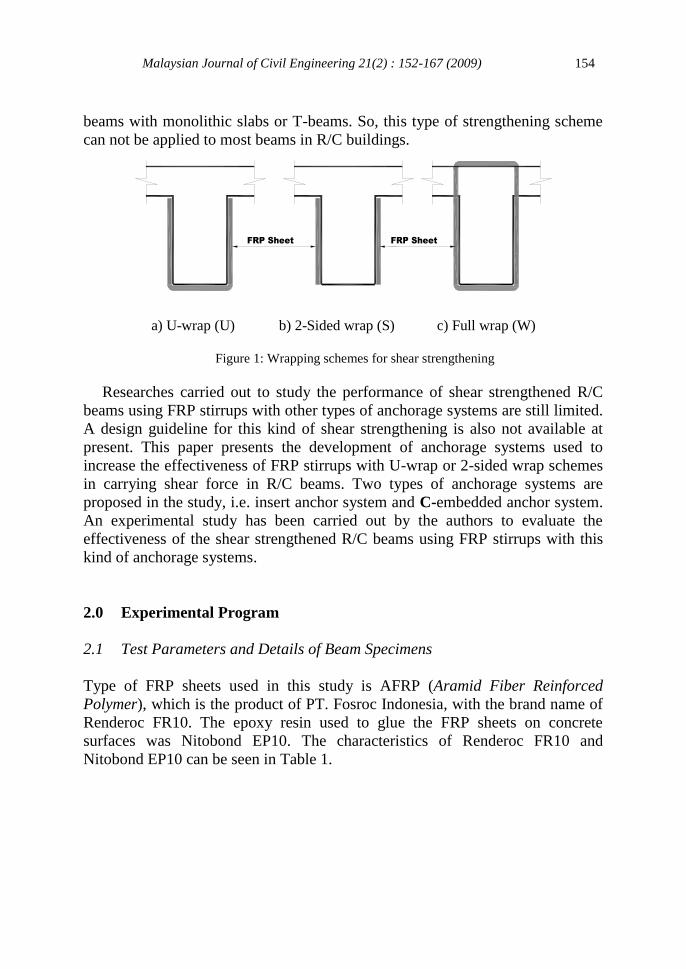
a) Insert anchor b) C-Embedded anchor
Figure 2: Anchorage systems developed in the study
Malaysian Journal of Civil Engineering 21(2) : 152-167 (2009) 156
Types of anchorage systems developed in this study can be seen in Fig. 2.
Insert anchors were made of local wood species, i.e. “Kamper Medan” that has a
good strength and durability. The anchors had the shaft diameter of 18 mm,
length of 25 mm and head diameter of 30 or 40 mm. The anchors were inserted
into pre-bored holes, in the test beams, that were pre-filled with epoxy resin
before inserting the anchors.
The C-embedded anchors were made by precutting the corners of the beam
cross-section, and then embedding the L-shaped ends of FRP sheets, followed by
patching the precut corners with grout material. A small rod bar was used to hold
the ends of the FRP sheets on their place before the precut corners were patched.
Dimension of the precut corner applied in C-embedded anchor was 20x20x40
mm. The material used for grouting was the same as that used for gluing the
FRP sheets to the concrete, i.e. epoxy resin.
Table 2: Variation of test parameters
No Sample
Code
Wrapping
Scheme
Width
(wf) mm
Space
(sf) mm
Anchor
Types
a/d
fe
1 BK - - - - 1.83 -
2 S40-TA S 40 80 TA 1.83 0.00128
3 U60-TA U 40 80 TA 1.83 0.00191
4 S40-AC S 40 80 AC 1.83 0.00128
5 U60-AC U 40 80 AC 1.83 0.00191
6 S40-D30 S 40 80 D30 1.83 0.00128
7 U60-D40 U 40 80 D40 1.83 0.00191
8 S40-D30S S 40 80 D30 1.94 0.00128
9 U60-D40S U 40 80 D40 1.94 0.00191
Note:
BK = Control Beams fe = (2.tf.wf)/(bw.sf)
a/d = Shear span to depth ratio tf = Thickness of FRP sheet
sf = Center to center space between FRP sheets
Table 2 shows test parameters varied in this study. The sample code of the
test specimens, consecutively from the left character, defines wrapping scheme
applied, i.e. 2-sided (S) or U-wrap (U), and then followed by thickness of sheets
used, i.e. 40 for AK-40 or 60 for AK-60. The next characters show type of
anchors used, i.e. TA (no anchors), AC (C-embedded anchor), or D30 or D40
(insert anchor with head diameter of 30 mm or 40 mm). The last character, if
Malaysian Journal of Civil Engineering 21(2) : 152-167 (2009) 157
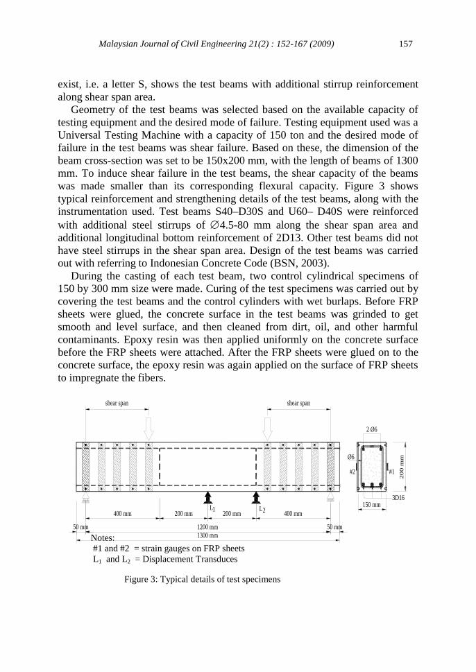
200 mm400 mm
50 mm
400 mm
1300 mm
1200 mm 50 mm
shear span
L1 2L
Ø6
2 Ø6
3D16
#1
150 mm
20
0 m
m
200 mm
shear span
#2
exist, i.e. a letter S, shows the test beams with additional stirrup reinforcement
along shear span area.
Geometry of the test beams was selected based on the available capacity of
testing equipment and the desired mode of failure. Testing equipment used was a
Universal Testing Machine with a capacity of 150 ton and the desired mode of
failure in the test beams was shear failure. Based on these, the dimension of the
beam cross-section was set to be 150x200 mm, with the length of beams of 1300
mm. To induce shear failure in the test beams, the shear capacity of the beams
was made smaller than its corresponding flexural capacity. Figure 3 shows
typical reinforcement and strengthening details of the test beams, along with the
instrumentation used. Test beams S40–D30S and U60– D40S were reinforced
with additional steel stirrups of 4.5-80 mm along the shear span area and
additional longitudinal bottom reinforcement of 2D13. Other test beams did not
have steel stirrups in the shear span area. Design of the test beams was carried
out with referring to Indonesian Concrete Code (BSN, 2003).
During the casting of each test beam, two control cylindrical specimens of
150 by 300 mm size were made. Curing of the test specimens was carried out by
covering the test beams and the control cylinders with wet burlaps. Before FRP
sheets were glued, the concrete surface in the test beams was grinded to get
smooth and level surface, and then cleaned from dirt, oil, and other harmful
contaminants. Epoxy resin was then applied uniformly on the concrete surface
before the FRP sheets were attached. After the FRP sheets were glued on to the
concrete surface, the epoxy resin was again applied on the surface of FRP sheets
to impregnate the fibers.
Figure 3: Typical details of test specimens
Notes:
#1 and #2 = strain gauges on FRP sheets
L1 and L2 = Displacement Transduces
Malaysian Journal of Civil Engineering 21(2) : 152-167 (2009) 158
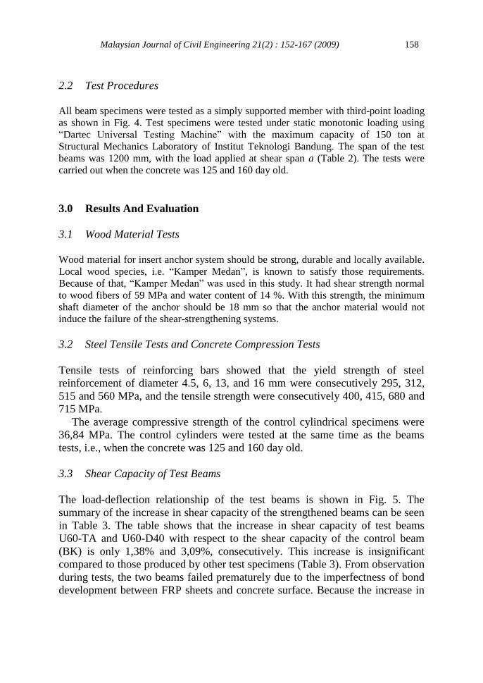
2.2 Test Procedures
All beam specimens were tested as a simply supported member with third-point loading
as shown in Fig. 4. Test specimens were tested under static monotonic loading using
“Dartec Universal Testing Machine” with the maximum capacity of 150 ton at
Structural Mechanics Laboratory of Institut Teknologi Bandung. The span of the test
beams was 1200 mm, with the load applied at shear span a (Table 2). The tests were
carried out when the concrete was 125 and 160 day old.
3.0 Results And Evaluation
3.1 Wood Material Tests
Wood material for insert anchor system should be strong, durable and locally available.
Local wood species, i.e. “Kamper Medan”, is known to satisfy those requirements.
Because of that, “Kamper Medan” was used in this study. It had shear strength normal
to wood fibers of 59 MPa and water content of 14 %. With this strength, the minimum
shaft diameter of the anchor should be 18 mm so that the anchor material would not
induce the failure of the shear-strengthening systems.
3.2 Steel Tensile Tests and Concrete Compression Tests
Tensile tests of reinforcing bars showed that the yield strength of steel
reinforcement of diameter 4.5, 6, 13, and 16 mm were consecutively 295, 312,
515 and 560 MPa, and the tensile strength were consecutively 400, 415, 680 and
715 MPa.
The average compressive strength of the control cylindrical specimens were
36,84 MPa. The control cylinders were tested at the same time as the beams
tests, i.e., when the concrete was 125 and 160 day old.
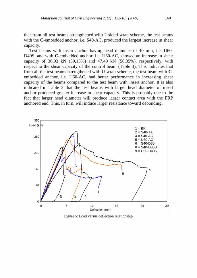
3.3 Shear Capacity of Test Beams
The load-deflection relationship of the test beams is shown in Fig. 5. The
summary of the increase in shear capacity of the strengthened beams can be seen
in Table 3. The table shows that the increase in shear capacity of test beams
U60-TA and U60-D40 with respect to the shear capacity of the control beam
(BK) is only 1,38% and 3,09%, consecutively. This increase is insignificant
compared to those produced by other test specimens (Table 3). From observation
during tests, the two beams failed prematurely due to the imperfectness of bond
development between FRP sheets and concrete surface. Because the increase in
Malaysian Journal of Civil Engineering 21(2) : 152-167 (2009) 159
SPECIMEN
shear span shear span
Spreader BeamHydraulic Jack
P
Roll L1 HingeL2
shear capacity of the beams is insignificant then the test results of the two beams
can be categorized as “outlier”.
Figure 4: Test setup of beam specimens
Shear capacity of test specimens S40-D30S and U60-D40S consists of
contribution from steel stirrups and from FRP stirrups. Analytically, the
contribution of steel stirrups in carrying shear force on test beams S40-D30S and
U60-D40S is 20.47 kN. With this, the contribution of FRP stirrups in carrying
the shear force on test beams S40-D30S and U60-D40S is 20.67 kN and 36.93
kN, consecutively. In other words, there is an increase of 21.91% and 39.15% in
shear capacity in those test beams, consecutively.
Based on the above results, the increase in shear capacity of test beam S40-
D30S is basically not significant compared to that produced by the test beam
without anchor, i.e. S40-TA. From observation on the test specimen, it was
found that the length of FRP sheet on test specimen S40 – D30S was not
adequate such that the ends of the FRP stirrups did not reach the top and bottom
edges of the beam. As a result, the anchorage produced at the ends of the FRP
stirrups did not work properly.
Table 3 also shows that the increase in shear capacity of test beams
strengthened with 2-sided wrap scheme, i.e. S40-AC, S40-D30, S40-D30S and
S40-TA, is 33.51%, 24.08%, 21.91% and 20.21% consecutively. Thus, test
beams S40-AC, S40-D30 and S40-D30S showed an increase of 11.06%, 3.22%,
and 1.41%, consecutively, in shear capacity compared to the shear capacity of
the test beam without anchor (i.e. S40-TA). From these results, it can be seen
Malaysian Journal of Civil Engineering 21(2) : 152-167 (2009) 160
Figure 5: Load versus deflection relationship
that from all test beams strengthened with 2-sided wrap scheme, the test beams
with the C-embedded anchor, i.e. S40-AC, produced the largest increase in shear
capacity.
Test beams with insert anchor having head diameter of 40 mm, i.e. U60-
D40S, and with C-embedded anchor, i.e. U60-AC, showed an increase in shear
capacity of 36,93 kN (39,15%) and 47,49 kN (50,35%), respectively, with
respect to the shear capacity of the control beam (Table 3). This indicates that
from all the test beams strengthened with U-wrap scheme, the test beam with C-
embedded anchor, i.e. U60-AC, had better performance in increasing shear
capacity of the beams compared to the test beam with insert anchor. It is also
indicated in Table 3 that the test beams with larger head diameter of insert
anchor produced greater increase in shear capacity. This is probably due to the
fact that larger head diameter will produce larger contact area with the FRP
anchored end. This, in turn, will induce larger resistance toward debonding.
0
70
140
210
280
350
0 6 12 18 24 30
Load (kN)
Deflection (mm)
1 2 4 6
8
1 = BK 2 = S40-TA 4 = S40-AC 5 = U60-AC 6 = S40-D30 8 = S40-D30S 9 = U60-D40S
5
9
Malaysian Journal of Civil Engineering 21(2) : 152-167 (2009) 161
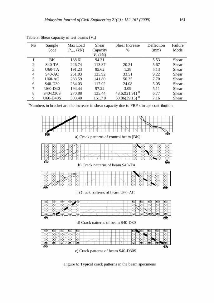
Table 3: Shear capacity of test beams (Vn)
No Sample
Code
Max Load
Pmax (kN)
Shear
Capacity
Vn (kN)
Shear Increase
%
Deflection
(mm)
Failure
Mode
1 BK 188.61 94.31 - 5.53 Shear
2 S40-TA 226.74 113.37 20.21 5.67 Shear
3 U60-TA 191.23 95.62 1.38 5.13 Shear
4 S40-AC 251.83 125.92 33.51 9.22 Shear
5 U60-AC 283.59 141.80 50.35 7.70 Shear
6 S40-D30 234.03 117.02 24.08 5.05 Shear
7 U60-D40 194.44 97.22 3.09 5.11 Shear
8 S40-D30S 270.88 135.44
43.62(21.91) 1)
6.77 Shear
9 U60-D40S 303.40 151.7 0 60.86(39.15)
1) 7.16 Shear
1)Numbers in bracket are the increase in shear capacity due to FRP stirrups contribution
e) Crack patterns of beam S40-D30S
d) Crack patterns of beam S40-D30
c) Crack patterns of beam U60-AC
a) Crack patterns of control beam [BK]
b) Crack patterns of beam S40-TA
Figure 6: Typical crack patterns in the beam specimens
Malaysian Journal of Civil Engineering 21(2) : 152-167 (2009) 162
3.4 Crack Patterns and Mode of Failure
In general, cracks were initiated at beams as flexural cracks. These cracks then
propagated to form diagonal tensile cracks in the shear span area (Fig. 6). At
failure, a major diagonal tensile crack was formed in the shear span at each
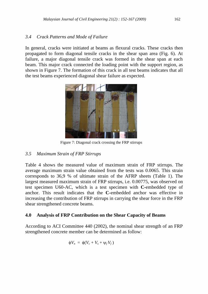
beam. This major crack connected the loading point with the support region, as
shown in Figure 7. The formation of this crack in all test beams indicates that all
the test beams experienced diagonal shear failure as expected.
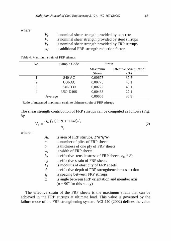
3.5 Maximum Strain of FRP Stirrups
Table 4 shows the measured value of maximum strain of FRP stirrups. The
average maximum strain value obtained from the tests was 0.0065. This strain
corresponds to 36,9 % of ultimate strain of the AFRP sheets (Table 1). The
largest measured maximum strain of FRP stirrups, i.e. 0.00775, was observed on
test specimen U60-AC, which is a test specimen with C-embedded type of
anchor. This result indicates that the C-embedded anchor was effective in
increasing the contribution of FRP stirrups in carrying the shear force in the FRP
shear strengthened concrete beams.
4.0 Analysis of FRP Contribution on the Shear Capacity of Beams
According to ACI Committee 440 (2002), the nominal shear strength of an FRP
strengthened concrete member can be determined as follow:
Vn = (Vc + Vs + f Vf )
Figure 7: Diagonal crack crossing the FRP stirrups
Malaysian Journal of Civil Engineering 21(2) : 152-167 (2009) 163
where:
Vc is nominal shear strength provided by concrete
Vs is nominal shear strength provided by steel stirrups
Vf is nominal shear strength provided by FRP stirrups
f is additional FRP-strength reduction factor
Table 4: Maximum strain of FRP stirrups
No. Sample Code Strain
Maximum
Strain
Effective Strain Ratio1
(%)
1 S40-AC 0,00675 37,5
2 U60-AC 0,00775 43,1
3 S40-D30 0,00722 40,1
4 U60-D40S 0,00488 27,1
Average 0,00665 36,9
1Ratio of measured maximum strain to ultimate strain of FRP stirrups
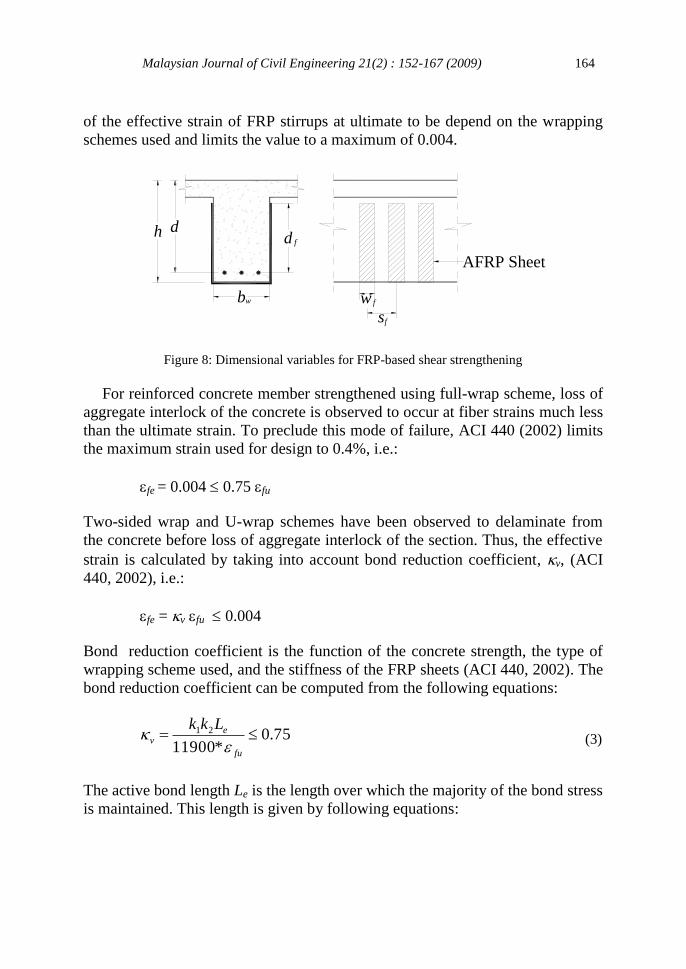
The shear strength contribution of FRP stirrups can be computed as follows (Fig.
8):
f
ffefv
fs
dfAV
)cos(sin (2)
where :
Afv is area of FRP stirrups, 2*n*tf*wf
n is number of plies of FRP sheets
tf is thickness of one ply of FRP sheets
wf is width of FRP sheets
ffe is effective tensile stress of FRP sheets, fe * Ef
fe is effective strain of FRP sheets
Ef is modulus of elasticity of FRP sheets
df is effective depth of FRP strengthened cross section
sf is spacing between FRP stirrups
is angle between FRP orientation and member axis
(α = 90o for this study)
The effective strain of the FRP sheets is the maximum strain that can be
achieved in the FRP stirrups at ultimate load. This value is governed by the
failure mode of the FRP strengthening system. ACI 440 (2002) defines the value
Malaysian Journal of Civil Engineering 21(2) : 152-167 (2009) 164
b
dd
w w f
fs
f
AFRP Sheet
h
of the effective strain of FRP stirrups at ultimate to be depend on the wrapping
schemes used and limits the value to a maximum of 0.004.
Figure 8: Dimensional variables for FRP-based shear strengthening
For reinforced concrete member strengthened using full-wrap scheme, loss of
aggregate interlock of the concrete is observed to occur at fiber strains much less
than the ultimate strain. To preclude this mode of failure, ACI 440 (2002) limits
the maximum strain used for design to 0.4%, i.e.:
fe = 0.004 0.75 fu
Two-sided wrap and U-wrap schemes have been observed to delaminate from
the concrete before loss of aggregate interlock of the section. Thus, the effective
strain is calculated by taking into account bond reduction coefficient, v, (ACI
440, 2002), i.e.:
fe = v fu 0.004
Bond reduction coefficient is the function of the concrete strength, the type of
wrapping scheme used, and the stiffness of the FRP sheets (ACI 440, 2002). The
bond reduction coefficient can be computed from the following equations:
(3)
The active bond length Le is the length over which the majority of the bond stress
is maintained. This length is given by following equations:
75.0*11900
21 fu
ev
Lkk
Malaysian Journal of Civil Engineering 21(2) : 152-167 (2009) 165
58.0)**(
23300
ff
eEtn
L (4)
3/2
127
'
fck (5)
f
ef
d
Ldk
2 for U-wraps (6)
f
ef
d
Ldk
22
for 2-sided wraps (7)
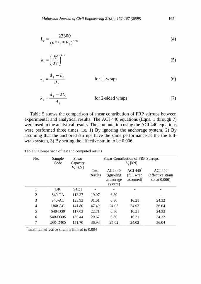
Table 5 shows the comparison of shear contribution of FRP stirrups between
experimental and analytical results. The ACI 440 equations (Eqns. 1 through 7)
were used in the analytical results. The computation using the ACI 440 equations
were performed three times, i.e. 1) By ignoring the anchorage system, 2) By
assuming that the anchored stirrups have the same performance as the the full-
wrap system, 3) By setting the effective strain to be 0.006.
Table 5: Comparison of test and computed results
No. Sample
Code
Shear
Capacity
Vn [kN]
Shear Contribution of FRP Stirrups,
Vf [kN]
Test
Results
ACI 440
(ignoring
anchorage
system)
ACI 440*
(full wrap
assumed)
ACI 440
(effective strain
set at 0.006)
1 BK 94.31 - - - -
2 S40-TA 113.37 19.07 6.80 - -
3 S40-AC 125.92 31.61 6.80 16.21 24.32
4 U60-AC 141.80 47.49 24.02 24.02 36.04
5 S40-D30 117.02 22.71 6.80 16.21 24.32
6 S40-D30S 135.44 20.67 6.80 16.21 24.32
7 U60-D40S 151.70 36.93 24.02 24.02 36.04
*maximum effective strain is limited to 0.004
Malaysian Journal of Civil Engineering 21(2) : 152-167 (2009) 166
It can be seen from the table that adopting the ACI 440 equations for each
respective wrapping scheme, and ignoring the anchorage system applied, results
in unreasonably lower estimate of FRP shear contribution. By adopting the
equations for full wrap system, the estimate value is closer to the experimental
results. The closest estimate from the analytical results is given by the analysis
which assume that the effective strain on the FRP stirrups can reach 0.006.
5.0 Conclusion
This paper presents experimental and analytical study for evaluating contribution
of FRP stirrups with anchored ends in resisting shear forces of shear
strengthened reinforced concrete beams. Anchorage systems proposed in this
study are insert anchor system and C-embedded anchor system. Based on the
results of this study, it can be concluded that:
1. The performance of FRP shear strengthened concrete members is very
dependent on the quality of FRP installation on the concrete member.
2. Shear strengthening methods using FRP stirrups with anchored ends were
found to be effective in increasing contribution of FRP stirrups in resisting
shear force in shear strengthened reinforced concrete beams. The C-
embedded anchor system showed better performance than the insert anchor
system.
3. The use of larger head diameter for the insert anchor produced larger shear
capacity in the beams. This shows that the matrix applied in between FRP
sheets and the contact surface of the head of the insert anchor influenced the
shear capacity of the beams.
4. Effective average strain of the FRP stirrups was found to be 0.00665. This
measured strain is larger than the maximum strain allowed by ACI Committee 440
(2002) for design, i.e. 0.004. This result indicates that the anchorage system
proposed is effective in enhancing the bond capacity between FRP sheets and
concrete surface. 5. The design equations for full-wrap system can be adopted for the design of
reinforced concrete beams strengthened using FRP stirrups with anchored
ends.
Malaysian Journal of Civil Engineering 21(2) : 152-167 (2009) 167
Acknowledgement
This research was carried out with the support from Research Grant 2004 of the
Department of Civil Engineering, Institut Teknologi Bandung. Aramid fibers and
epoxy resin used in the research were obtained from PT. Fosroc Indonesia. The
authors would like to thanks those for all the supports given. Two anonymous
reviewers are thanked for their helpful and constructive criticism.
References
ACI Committee 440 (2002) Guide for the Design and Construction of Externally Bonded FRP
Systems for Strengthening Concrete Structures (ACI 440.2R-02). American Concrete
Institute, Farmington Hills, MI, 45 pp.
Adhikary, B. B., Mutsuyoshi, H. and Ashraf, M. (2004) Shear Strengthening of Reinforced
Concrete Beams Using Fiber-Reinforced Polymer Sheets with Bonded Anchorage. ACI
Structural Journal, 101 (5): 660-668.
Bousselham, A. and Chaallal, O. (2004) Shear Strengthening Reinforced Concrete Beams with
Fiber-Reinforced Polymer: Assessment of Influencing Parameters and Required Research.
ACI Structural Journal, 101 (2): 219-227.
BSN (2003) Indonesian Concrete Code for Buildings (SNI-03-2847-2003). Indonesian National
Standard, 278 pp.
Chajes, M., Januska, T., Mertz, D., Thomson, T., and Finch, W. (1995) Shear Strengthening of
Reinforced Concrete Beams Using Externally Applied Composite Fabrics. ACI Structural
Journal, 92 (3): 295-303.
Imran, I., Simatupang, P.H., and Purnomo, S. (2003) Experimental Study on the Shear–
Strengthened RC Beams Wrapped with Aramid Fibre Sheet. Proceedings of the 5th
Asia-
Pacific Structural Engineering and Construction Conference. Johor Bahru, Malaysia, 233 -
252.
Khalifa, A., Gold, W., Nanni, A., and Abel-Aziz M. (1998) Contribution of Externally Bonded
FRP to the Shear Capacity of RC Flexural Members. Journal of Composites in Construction,
2 (4): 195-203.
PT Fosroc Indonesia (2000) Technical Guide and Material Properties of Aramid Fibers (Kevlar).
Fosroc, 10 pp.