Embed Size (px)
Citation preview
NASA/TM--1998-206528
ISWE: A Case Study of TechnologyUtilizationM.P. Benfield, D.P. Mitchell, M.T. Vanhooser, D.B. Landrum
Marshall Space Flight Center, Marshall Space Flight Center, Alabama
National Aeronautics and
Space Administration
Marshall Space Flight Center
March 1998

Acknowledgments
The authors of this paper would like to thank the following people for their assistance in the writing of this paper:
Mr. Neil Rainwater
Mr. Tony ClarkMs. Karen Oliver
Ms. Tamara Landers
Ms. Carolyn RussellMr. Bill Broad
Mr. Stephen Hall
Mr. Alexander Zagrebelnij
Available from:
NASA Center for AeroSpace Information
800 Elkridge Landing RoadLinthicum Heights, MD 21090-2934
(301) 621-0390
National Technical Information Service
5285 Port Royal Road
Springfield, VA 22161
(703) 487--4650
ii

Table of Contents
PARAGRAPH PAGE
List of Figures ....................................................................................................................... v
List of Tables ....................................................................................................................... v
Acronyms List ..................................................................................................................... vi
Preface ................................................................................................................................ vii
Introduction .......................................................................................................................... 1
Section 1: Background ......................................................................................................... 2
Why Weld in Space? ........................................................................................................ 2History of Space Welding ................................................................................................ 4History of ISWE ............................................................. , ................................................. 5ISWE Experiment Overview ............................................................................................ 5ISWE Development .......................................................................................................... 7
Section 2: General Problems ................................................................................................ 8
Language Barrier .............................................................................................................. 8Openness .......................................................................................................................... 9Limited Analysis/Testing Data .................................................................................... 10
Section 3: Specific Problems ............................................................................................. 11
NBS Lubricant ................................................................................................................ 11Threaded Fastener Preload ............................................................................................ 11
Materials ........................................................................................................... _............ 12EMI Testing .................................................................................................................... 13Temperature/Thermal ................................................................................................... 14Test Procedures .............................................................................................................. 17
Section 4: Safety ................................................................................................................ 18
Contamination ............................................................................................................... 18Light Intensity ................................................................................................................ 19
Section 5: What About ISO? ............................................................................................. 20
The International Organization for Standardization (ISO) ........................................... 20ISO Standards and ISWE .............................................................................................. 20Concerns with ISO ......................................................................................................... 21
Conclusion .......................................................................................................................... 21
References ........................................................................................................................... 22
iil


Figure 1.
Figure 2.
Figure 3.
Figure 4.
Figure 5.
Figure 6.
List of Figures
Current ISWE Configuration ................................................................................ 1
Standard Process for a Payload Design Acceptance ......................................... 7
ISWE's Design Acceptance Process .................................................................... 8
Flow of Work for Establishing Fastener Preloads ............................................ 12
PWI Thermal Vacuum Test ........... ; .................................................................... 15
Thermal Tests ..................................................................................................... 16
Figure 7. MSFC Thermal Cycle Tool Tests ........................................................................ 17
List of Tables
PAGE
Table 1. Components of ISWE ............................................................................................ 3
Table 2. Steps Toward ISWE Creation ............................................................................... 5
Table 3. Required NASA Analyses and Their Sources .................................................... 10
V

Acronyms List
BICSCATCCCDRCPCSDCTDIBEMIEMCEMUEVAFTGOSTISSISWE
jscMPEMPESSMSDSMSFCNASANBSNSAUNSTSPDRPIBPIPPRRPWIRIDRSHSFR-RSFR-TSTTBTBE
TQCMTSTSAUHTUWS
Beam Impingement Control SystemCathode Alignment ToolContamination Curtain
Critical Design ReviewControl Panel
Cable Stowage Device
Coating ToolData Interface Box
Electromagnetic InterferenceElectromagnetic CompatibilityExtra-vehicular Mobility UnitExtra-Vehicular ActivityFiller Wire Welding ToolRussian State Standard
International Space StationInternational Space Welding Experiment
Johnson Space CenterMission Peculiar EquipmentMission Peculiar Experiment Support StructureMaterial Safety Data SheetMarshall Space Flight CenterNational Aeronautics and Space Administration
Neutral Buoyancy SimulatorNational Space Agency of the UkraineNational Space Transportation System
Preliminary Design ReviewPower Interface BoxPush-In-Place
Project Requirements ReviewPaton Welding InstituteReview Item DiscrepancyRotating Sample HolderSliding Foot Restraint RailSliding Foot Restraint TrolleyStandard Tool
Technological Block
Teledyne Brown EngineeringThermally Controlled Quartz MicrobalanceTest Set
Tool Stowage AssemblyUniversal Hand Tool
Universal Welding System
vi

Preface
The International Space Welding Experiment (ISWE) was a joint venture between the
NASA George C. Marshall Space Flight Center (MSFC) in Huntsville, Alabama and the
E.O. Paton Welding Institute (PWI) in Kiev, Ukraine. Manifested as an element of the
United States Micorgravity Payload - 4 (USMP-4), ISWE was "to demonstrate the
feasibility of welding as an operational maintenance process using equipment developed
by the Paton Welding Institute (PWI)" (Russel, et. al. 1996). On December 6, 1996,
ISWE was demanifested due to conflicts between various experiments vying for limited
astronaut space walking opportunities. Current plans are possible manifesting on a
shuttle flight to the Russian space station MIR for the welding process to be performed
by Russian cosmonauts.
The paper contained herein was written before the demanifesting of ISWE and
describes the ISWE project for operations on the Space Shuttle. It addresses selected
issues that during hardware development. To keep the content of the paper from
changing, the authors decided to publish the paper as is.
vii


Introduction
TheInternationalSpaceWelding Experiment (ISWE) is a joint venture between the
E.O. Paton Welding Institute (PW10 of Kiev, Ukraine and the National Aeronautics and
Space Administration (NASA) of the United States government. Its purpose is to
evaluate the Ukrainian developed Universal electron beam welding system as a
contingency repair tool for the International Space Station (ISS) and to assess the
capability for long term maintenance of space structures, including debris impacts to
habitable modules and repairs of fluid line leaks (Rainwater 1995). Figure 1 depicts the
current configuration of the LSWE.
International Space Welding Experiment (ISWE)
BEAM MPINGE MENTSHIELD(BIS)
SAMPLE HOLDR (RSI._
OCK 0"B)
POWER INTERFACE BOX (PIB)
(BEI-IND TB and TSA)
(TSA)
3NMENT TOOL (C/g)
BIC YOKE
CONTROL PAllEt. (CP)
SLIDING FOOT RESTRAINT
TROLLY (SLFR)
OBSERVER CREWMAN CI
B ETACLOTHS'mUCTURAL
C LOS EOUT (MP E)
RAIL SU PPORT
,,l ASSEM Bt.Y(M PE)
Figure 1. Current ISWE Configuration
PWI is providing the Universal welding system and supporting equipment and
NASA is providing the vehicle, the Space Shuttle, the Mission Peculiar Equipment
Support Structure carrier, and interface hardware, as well as engineering support at the
Marshall Space Flight Center (MSFC) in Huntsville, Alabama. Table 1 illustrates the
different components of the ISWE as well as their provider and function.
With the introduction of an international partner several issues have arisen as to the
way in which the experiment will be qualified as a flyable system aboard another
agency's space vehicle. These issues are primarily due to the distinctly different

technical standardsand practices that NASA and PWI use in their respective space
businesses, but issues of interagency communication and openness have also arisen.
Together, these issues have significantly complicated what began as a small scale pilot
project in international space cooperation. With other international projects likely in the
future, it is imperative that a consensus of standards and practices for international
cooperation be established for the 21st century and beyond.
Section 1: Background
In this section the concept of welding in space is discussed. A historical look at
space welding and the political foundation of ISWE is also presented as well as an
ISWE experiment overview. This background includes a description of the process for
qualifying ISWE to fly on the U.S. space shuttle.
Why Weld in Space?
In addition to initial construction tasks, long term operations in space will require
performance of maintenance tasks such as repair of micrometeroid damage, leaking fluid
lines, stuck instruments, contaminated surfaces, etc. These tasks will require welding or
the development of alternative processes. Currently, space welding is considered a high
risk endeavor due to unknowns about operational characteristics of such a process in
the microgravity of space. Therefore, it is imperative that welding equipment and
procedures be demonstrated in the space environment before welding operations can be
included in the repertoire of routine space technology. With a metals processing system
qualified for assembly, construction or processing of hardware in space and knowing
appropriate welding techniques, restrictions, and weld properties, the aerospace design
community can design for welding in space (Russell, et al. 1996).
2

Table1. Components of ISWE
Component Name Provider
mcs)
PowerInteface
Box (PIB)
MSFC
MSFC
Inteface MSFCBox (DIB)
Control PWI
Panel (CP)
CableStowage PWIDevices
@
Rotating
Sample |Holder / PWI
LL____/_Sliding
Foot PWIRestraint
(SFR)
Technological
Block (TB)
Tool
Tool StowageAssembly/:athode AIiRnmenrool (TSA/CAT)
EMIrProtective
._arment
Visor StowageBox
Weld
Samples
MPE
PWI
PWI
PWI
PWI
jsc
.ISC
MSFC
MSPC
Function
To protect the orbiter and the rest of the USMP-4
experiments from contamination of the weldingparticles and impingment of the electron beam
transients and noise to (or from) the TB, adds athird inhibit to guard against failues that couldresult in beam on condition
Provides signal splitting and conditioning tointerface TB telemetry with the Spacelab and
Orbiter data handling systems
Provides EVA controls/feedback for:
TB main power on/off, setting of beam power
modes, and setting of filler wire feed rate
Provides stowage for tool cables during launch/
landing & when not in use during operations
Structure which allows the drum mountedplates/samples to be manually rotated in front of
the welder for ease of processing
Provides translation capability across the ISWE
worksite with the astronaut secured in a
PFR boot'plate. Made up of the following: SFR-Trolley, SFR-Rail, SFR-T launch lock
Main power source and controller for the
Universal welding system
Provides IVA controls/feedback for:
viewing telemetry from TB, TB main power off,TB main power on, cathode select, and beam teststart
5 modular hand-held electron beam welding
tools; 1 Standard Tool (ST)- welding, cutting,brazing, 3 Filler Tools (FT) -filler welding,1 Coating Tool (CT) -coating
Provides the following: stowage for tools duringlaunch/landing & when not in use by the
astronaut, on-orbit alignment of filler wire feed
mechanism to electrode beam if cathode changed
Provide protection forthe EMUduring ISWE operations
Stow the visors used on the shieldof the EMU helmet
Replicate typical weld configurationand potential ISS weld scenarios
to accomodate experiment hardwareto the STS system
3

History of SpaceWelding
Welding in space is not a revolutionary Concept. Since the 1960's the former U.S.S.R.
and the United States have been conducting experiments in space welding. In 1969 the
"Vulkan" automatic welder was launched on Soyuz 6 to compare three types of welding
for potential space application: electron beam, low-pressure constricted plasma jet, and
consumable electrode. As a result of the Vulkan project, the Soviet space program
(including the Ukrainians at the time) concluded that electron beam welding was the
most promising process for space welding due to its versatility and low power
consumption (Avduyevsky, 1985).
Throughout the next two decades, the USSR continued to demonstrate electron
beam welding in space. The "Isparitel" was developed by the PWI, and was launched to
the Salyut-6 space station in 1979 to test production of vapor deposited coatings.
Isparitel used an electron beam to heat the coating materials, causing them to evaporate.
The vapor was condensed on multiple substrates, both metallic and non-metallic. Over
two hundred samples of widely varying coatings were produced with this hardware
during its three years aboard Salyut-6. An improved unit, Isparitel M, was developed
and launched to the Salyut-7 space station in 1983. Tin-silver brazing alloys, and silver-
germanium eutectic alloys, were among the samples processed the following year. The
PWI also developed the "Yantar" unit which was launched to the Mir space station in
1988. This hardware used an electron beam to produce vapor deposited coatings on
both metallic and polymeric substrates, and also allowed welding of very thin metallicr
specimens. This unit, like all of the preceding units mentioned above, was automated
and therefore only produced samples where the parameters were well known and easily
preset (Avduyevsky, 1985).
In an effort to provide a more flexible tool, the PWI developed the Universal Hand
Tool (UHT) which was launched to the Salyut-7 space station in 1984. The UHT
consisted of a power control electronics module and hand held electron beam gun. The
0.75 kilowatt (kW) UHT was first used to conduct Extra-Vehicular Activity (EVA)
welding aboard Salyut-7 in July of 1984. The EVA lasted for just over three hours and=
involved two cosmonauts each performing a variety of welding, cutting, brazing, and
coating operations with the UHT. This EVA was performed with ambient lighting and
required approximately 3 months of crew training. The UHT electronics module and
hand held electron beam welding gun were mounted to the exterior of the Salyut-7
station at the start of the EVA, prior to beginning the welding operations. Additional
experiments aboard Salyut-7 were conducted in 1986 and involved welding truss
structures and structural subassemblies representative of space station components. The
UHT hardware had been in space since the initial testing done in 1984, and functioned
flawlessly iAvduyevsky, 1985). A modified version of this 1984 UHT model, the
"Universal Welding System" designed for use on the Russian Space Station MIR, was
chosen for the ISWE project.
4

The United States began welding in space in 1973 on board Skylab 3 utilizing the
electron beam concept. With the M512, astronauts on board Skylab demonstrated the
capability to repair structures in space that had been exposed for long durations.
Skylab's demise removed the need for a space welding capability and further U.S.
research was halted.
History of ISWE
As design, construction, and maintenance plans were developed for the International
Space Station (ISS), it became apparent that the need to weld in space was inevitable.
But, since the last U.S. demonstration of welding was the 1973 flight of the M512, the
NASA engineers felt that an operational system could not be developed in the short-
term ISS schedule (and within allowable cost). Furthermore, with the collapse of the
Soviet Union in 1991, various Soviet Union technologies (such as the Universal Welding
System) and experience were becoming available to overseas countries. Prompted by
the McDonnell Douglas Corporation, NASA, the PWI and the Clinton administration's
desire for cooperative space ventures with the former Soviet states, the United States
and the Paton Welding Institute began active negotiations to perform a joint flight
demonstration of the Universal technology. This process, summarized in table 2,
resulted in the development of the ISWE.
Date
1992-1993
April 1993
September1993
October 1993
November1993
January 1994
March 1994
July 1994
Table 2. Steps Toward ISWE Creation
Occurrence
McDonnell Douglas Corporation and Ukrainians test UHT
workstation in Neutral Buoyancy Simulator (NBS) tank
Fourth Call for Hight Demonstrations from NASA HeadquartersSpace Act Agreement between MSFC & PWI - 1st project with theUkrainians and MSFC - conduct demonstration of UHT on KC-135
Ukrainians arrive for preparation of tests
ISWE picked for further study as possible demonstration on shuttle
KC-135 fli'ght
130-150 welds processed
President Bill Clinton goes to the Ukraine - talks of cooperation inspace between the two nations
Delegation from the National Space Agency of _e Ukraine meets at
NASA Headquarters in Washington, D.C. - 1997 flightdemonstration of the UHT discussed
ISWE Experiment Overview
The ISWE will involve a single, two person EVA with a third IVA crew member in
support at the aft flight deck. The heart of the ISWE is the Universal Welding System
(UWS). The UWS is a hand-held electron beam welding gun with specialized
attachments, and integral cable for connection to the Technological Block (TB). The
5

electron beam is produced by heating a metal filament within the cathode to produce
electrons which are then accelerated by the potential difference between the cathode and
anode, and focused by the anode configuration. The power cable feeds into the tool
through the base of the handle. The tools are designed to accept attachments which
allow the operator to perform different operations, including welding with filler wire and
coating by vapor deposition. Although the welding tools are designed for use as modular
units, five electron beam tools are planned for use on this flight so that no on-orbit tool
reconfiguration is necessary. The tools will simply be exchanged for the different tasks.
Exchanging the welding guns will require removing power, disconnecting the integral
power cable from the TB, stowage of the hand tool, and connecting the power cable for
the new tool. The power cable connection is identical for each tool. Each electron beam
tool weighs between 4.5 and 6.5 kg, including the integral cable, depending on the
configuration. Each tool is equipped with a pair of green LEDs on the upper sides of the
tool which indicate trigger position. All of the crew interface labels will be in English and
Ukrainian.
The five tools to be flown include a standard tool (ST) for general purpose
welding/brazing/cutting, three for welding with filler wire, and one for coating by vapor
deposition. The 4.5 kg. ST is designed to weld aluminum, stainless steel, and titanium
samples up to 2 mm thick, and cut samples up to 1.5 mm. The filler wire feed tools
(each 6.5 kg.) include one with 2319 aluminum filler wire, one with 5356 aluminum filler
wire, and one with 308 stainless steel filler wire. The 2319 filler wire is intended for use
on 2219 aluminum samples. The 5356 filler wire is intended for use on 5456 aluminum
samples. The 308 stainless steel filler wire is intended for use on the 304 stainless steel
plates. The filler wire will be fed at a fixed selectable rate from a motorized spool
attached to the side of the head. The filler wire feed rate is selected by the welding
operator using the Universal control panel. The filler wire is necessary for welds where
the joint is not very tight. It is also necessary for all welds of 5456 aluminum as this
alloy will crack without filler wire. The motorized spools will dispense the filler wire at
10.83, 11.94, and 13.06 millimeters per second. Power for the spool motor is provided
by the electron beam tool.
The experiment sample materials will include 2219 aluminum from which the U.S.,
Japanese, and European space station modules will be made, 5356 aluminum from
which the Russian modules are made, 304 stainless steel, and Ti-6AI-4V titanium alloy.
The welds will be performed at a rate determined by ground testing at MSFC. The
coating experiments will involve the application of three optical coatings. The
magnesium fluoride (MgF2), silver (Ag) and gold (Au) will be applied to the silica glass
substrates using the hand tool with the vapor deposition attachment. The coating
experiments will include three fixtures, each containing one inch diameter circular
substrates. The coatings will be applied until they are visibly opaque, roughly just over
one thousand angstroms thick.
6

ISWE Development
Whenanexperimenthasbeenchosenby NASA to fly on boardthespaceshuttle the
payload must go through a process to qualify its design and fabrication as flight-ready
hardware. A standard development process is shown in Figure 2. As shown in Figure 3,
ISWE's development process differs from the standard due to the additional UWS
review and several delta Phase 0/1 Safety Reviews. Since the LFWS was an existing
design by PWI, the I.FWS review allowed NASA to evaluate the design in terms of safetyand interfaces.
During each ISWE design review, issues arose due to the difference in standards and
practices between NASA and PWI. For each issue, engineers at both the Marshall
Space Flight Center and the Paton Welding Institute had to devise a solution that would
minimize cost and schedule impact without jeopardizing safety of the astronaut crew or
the orbiter. This paper details each design review and discusses some of the problems
that occurred as well as the solutions that were devised by the ISWE team. Although
many of the concerns initially seem small, they were amplified due to the philosophical
differences of Ukraine and the U.S. in qualifying a payload to fly into space.
Program Project Requirements Preliminary Design
Development Review Review
Phase 0/1 Phase 2 Phase 3
Safety Review Critical Design Safety Review SafetyReview
Figure 2. Standard Process for Payload Design/Safety Acceptance
7

r _ • m • • •
• Universal Welding i Project ReqmrementsProgram _, System Review _ Review
ATP ,February 13- March28, 1995 , April 27- May 26, 1995
_'P"reliminary Design •
ReviewQugust 28 - September 26, 1995
• Critical Design •
Review I _/
I;
Figure 3. ISWE's Design/Safety Acceptance Process
Section 2: General Problems
Several general problems have plagued ISWE during the entire development process.
These include: language barrier, willingness to share information, and limited
analysis/testing data.
Language Barrier
With any effort being undertaken by international partners that speak different
languages, problems are inherently possible and probable. With ISWE's partner being
the Paton Welding Institute in Kiev, Ukraine, translators were required to speak between
the two centers to enable the engineers to understand each other. Weekly telecons were
held to discuss any problems of the week and to generally touch base with the other
engineers. These conversations/telecons were time consuming because of the translation
required between the two parties. But, there was still a risk of
8

misinterpretation/mistranslationinvolved. Therefore,anyagreementsmadeduring
theseteleconswereusually written down and faxedor mailed to the otherparty tomakesure the two sides were in total agreement. But, when those faxes or letters
arrived, they would have to be translated causing an additional delay of several days.
Over time both sides mutually adapted to this situation.
NASA should encourage and, in some cases, require the engineers with international
projects to take classes to be able to better communicate with their foreign counterparts.
This action would not eliminate the need for translation services, but would enhance the
working relationship by showing the foreign counterpart a general interest in their culture
and their language, making them feel a more integrated part of the team.
Openness
The U.S. and the former Soviet states have long been rivals in the space arena, each
vying to be the preeminent space power of Earth. With ISWE, both of NASA and PWI
were to become partners to achieve one common goal. Decades of rivalry had to be put
aside to reach the completion of ISWE. Naturally, in the beginning there was
apprehension on the part of both parties due to the unknowns of working together.
Initially, the Ukrainians were hesitant to disclose information vital to the integration
and qualification of the Universal hardware. Unfamiliar with a free-market society, the
Ukrainians were concerned that the information provided to NASA would become
public domain and could therefore be taken by any interested American company. This
false perception was allayed by conveying to the Ukrainians the content of Public Law
#18-1905, "Whoever, being an officer or employee of the United States or of any
department or agency there of, ... publishes, divulges, discloses, or makes known in any
manner or to any extent not authorized by law any information coming to him or in the
course of his employment or official duties or by reason of any examination or
investigation ... shall be fined not more than $1000, or imprisoned not more than one
year, or both; and shall be removed from office or employment." Under this law the
Ukrainian hardware was labeled proprietary information, thereby protecting it from the
American public. This action, in turn, gave Paton the confidence with which to proceed
with the disclosure of their design.
Having taken this first step, the Ukraini_s and NASA were now able to work more
closely knowing that the other would secure their information. Trust is a vital part of
cooperation that must be firmly in place if the space faring nations wish to effectively
work with one another. ISWE can serve as a model of such cooperation. NASA and
PWI both went through a time of building a working relationship of openness and trust.
With this in place, future cooperative ventures with PWI will run more smoothly.
9

Limited Analysis/Testing Data
The UWS review brought out a major difference between NASA and PWI's
approach to hardware development. For several decades NASA has moved toward
utilizing computer analysis of designs to complement actual testing. This appraoch has
continued to prove effective in qualifying hardware for space flight. However, the
former Soviet Union states have a very different philosophy. They believe in
overdesigning a system and then testing it to its limits (Zagrebelnij, 1995). This
approach is initially mXore costly because two complete systems must be manufactured
as well as the risk that the design fails to meet criteria and must be redesigned. The
analysis method minimizes the risk to the project and maintains the life of the hardware.
But, the analysis approach has its downfalls as well. Computational analysis cannot
fully simulate the true environments that the hardware will be subjected to in space. If
any design shortcoming appears after the system is on orbit, it is often too late if failures
occur. There is a middle ground for hardware development. Performing some level of
initial analyses to confirm the design's requirements are met and then testing to validate
(or benchmark) the analysis, the hardware can prove qualification. With ISWE, several
analyses were done as well as tests to validate the analyses.
Because of the lack of reliance on analysis by the Ukrainians and the fact that the
UWS was designed as a portable unit that the Russians launched inside the crew cabin
and transported outside to perform operations, it was decided that MSFC would do the
analytical work of the qualification program. NASA has a specific analysis protocol
that must be performed in order to qualify a payload for flight on the shuttle. This
protocol is summarized in Table 3 along with the source document that requires them.
Table 3.
AnalysisThe_-,al
Stress
Dynamic
Required NASA Analyses and their SourcesSource
SLP/2104-10, Appendix K
Human Factors
FractureMaterials
Venting
Static Envelope
JA-081 , JA-2294, NSTS 21000-IDD-MDK
JA-081, JA-2294NASA-STD-3000, JSC 26626A
JA-081, JA-276, NSTS 21000-IDD-MDK
JA-081
JA-081, ICD-2-19001, SLP/2104 MainVolume
ICD-B-MPESS-A/MPESS-B, NSTS 21000-
IDD-MDK, JA-2294
Once these analyses are performed, the hardware is then subjected in ground tests to the
flight environments that the analyses predicts that it will see. By passing these tests the
hardware is qualified for flight. From a safety standpoint, allowing Marshall to do these
analyses resulted in a documented record that ISWE satisfied the requirements imposed
on it.
l0

Section3: Specific Problems
NBS Lubricant
Whenaprojectinvolvesextra-vehicularactivity (EVA), Neutral Buoyancy
Simulation (NBS) testing is recommended. By conducting NBS testing, astronauts, as
well as the experiment's engineering team, can evaluate the functional and ergonomic
design of the hardware. Since the ISWE calls for a six hour EVA to conduct the welding
operation, a test was run to determine the crew interfaces acceptability. With NBS
testing, moving parts within the experiment must have water-compatible lubricant. The
lubricant that PWI was going to provide did not have a Material Safety Data Sheet
(MSDS) which is required to assure no toxicity concerns exist when put in the water for
the diver's safety. Therefore, MSFC had to provide the NASA approved standard
lubricants to PWI so they could be incorporated before the NBS hardware was shippedfrom Kiev to Huntsville.
Threaded Fastener Preload
The threaded fastener preload issue is another example of the situations that occur
due to the different NASA and PWI philosophies. Upon review of the ISWE design at
PDR a major issue arose because there was no fastener preload indicated in the PWI
drawings. Further investigation revealed that PWI does not apply preload in fasteners.
It is standard U.S. aerospace industry practice to apply preloads to all fasteners loaded
in tension. Both MSFC-STD-486 and NSTS 08307 require that NASA flight hardware to
have nonzero preloads applied to all fasteners (Denniston 1995).
To solve the preload issue, a procedure developed by Marshall and approved by
PWI, was introduced to determine the fastener preloads. Figure 4 shows the flow of
work for establishing the fastener preloads. Note the complex set of decisions and
actions required to rectify a basic issue of nonsimilar design practices. MSFC performed
torque tension testing on fastener and joint configurations representative of those found
in the PWI hardware. MSFC also provided PWI tooling (torque wrenches) to install the
fasteners with the test determined pre-loads. MSFC also supplied thread locking
compound (Ioctite) identical to that used in the testing so that all parameters remained
the same as in testing.
This one issue caused a tremendous amount of unplanned work due to a small
difference in design and manufacturing standards. If common standards were
implemented this would not have had to happen. NASA and PWI could both feel that
the design of the ISWE was safe and reliable from both sides.
11

PWI Id_ngrlas S_et7CrttJc_ F:ui_ nets
I PWt Prepares Test I]Samples For MSFC J
I pWI Arrlv_ FromThe Ukraine
MSFC Informs pwI
Precis_ly What IsNeeded For Testing
-_ MSFC R_ctlves TestSampbes From pWI
Tension And TensilePull Tests
lMSFC AssessesC_ i
And Schldule Impact
Of Using DomesticFasteners
IpW'[ ReturnsTo
The Ukrzlne i
pwIStartsModlfytng [_.dIX.dips Per Prtlfmlnary [
TBE Stress Analysts ]i m
t PWl Co._uu Modl_aS [Desllla Per ModUt_ TBE [_m
Stress Analysts J
PWI Redesign or ]Fastener Jolnta
Compkted
I
I YMSFC Provides Torque- [ _ [MSFC And PWI Make
Tension Curves And Futeazr _ _m'] I_clslou As To Source
Tenston Results To TBE I ] Of Fasteners
!
TSE Siam Re.Jew [Of Fastener Appllod ]
TBE Provides F_tener]Applied Loads To MSF 9
TBE Starts Stress [
Analysis Of Safety[
Critical Fastener [Jolnt_ [
TBE Reports Preliminary ]
Results Of Fastener Analysis [
To MSFC And pWI ]I
ITBE Modifies Fastener ]
_l_-_i Strm Analysis Per I
I I
TBE Stress Analysis [Of Fasteners Completed ]
I
TBE Reviews ]Modified PWI
Joint Designs
I
Figure 4. Flow of Work for Establishing Fastener Preloads
Materials
From the beginning of ISWE, materials were of great concern. During the UWS
review, several Review Item Discrepancies (RIDs) were written against the design due to
the differences between material characterization of the two agencies. Examples of the
type of materials issues raised during the review are as follows:
1) All hardware located in the cargo bay of the orbiter is subject to contamination
by thermally induced vacuum outgassing. There was no data to support that this was a
common practice of PWI (Landers 1995).
2) No materials list was provided for the power cables, so the acceptability
(flammability issues) for use on the shuttle could not be determined (Landers 1995).
12

3) All materials listed in the drawing packages referred to GOST standards, but did
not contain them. To evaluate materials of construction in a stress analysis the GOST
standards and material properties of the various materials were needed (Landers 1995).
The solutions to these problems proved to be very creative on the part of the
Materials and Processes Laboratory as well as the entire ISWE team.
1) Hardware located in the cargo bay of the orbiter is subject to the thermal vacuum
stability requirements of JSC-SP-R-0022. It was agreed that all of the hardware located
in the cargo bay must go through a thermal bakeout period on the ground. By thermally
baking the component, any impurity or residue will be offgassed before the component is
flown on the shuttle. If this procedure is not carried out the shuttle's radiators could be
contaminated or damaged. As a result, the ISWE team decided to conduct the thermal
bakeout at Marshall with PWI supervising the process as well as agreeing to the
temperatures the components would be baked at a pressure of 10 -6 torr or less and a
temperature of 10ooC greater than expected maximum on-orbit while holding the
Thermally Controlled Quartz Microbalances (TQCM) at 10 C less than expected
minimum in flight).
2) The ISWE team decided to manufacture all flight cables at MSFC using
appropriate, approved standards, with the exception of the UWS cables, to alleviate
any questions from the material's experts about their composition. The UWS cables
were made acceptable for flight by installing a braided zipper tubing and an overwrap
of Mystic Tape.
3) To certify the material properties of the Ukrainian built components, the
Materials and Processes Laboratory used the same procedure they had used with
Russian built components on the Space Station. PWI provided the information from the
GOST standards to the Materials and Processes Laboratory which then made an in-
depth analysis of the material (i.e., chemical, physical properties, etc.). Rather than
examine the multitude of different materials in the system, the most commonly used ten
alloys were selected and compared to their U.S. equivalent to determine the
acceptablility of the PWI supplied GOST standard properties. As a result of the
analysis, eight of the ten alloys appeared to have mechanical properties that were
similar to their USA equivalents. To provide a confidence level in the other alloys, the
annealed properties were used. With this work complete, the stress analysis could be
done with a high degree of confidence in the results.
EMI Testing
Within NASA there are several requirements for conducting EMI tests. To fly on the
shuttle, ICD-2-19001 "Shuttle Orbiter/Cargo Standard Interfaces" states that the
payload must provide documentation to prove compliance. This documentation takes
the form of an EMI test report. EMI testing became a factor from the very start of the
13

ISWEproject. Testingduring theUWSreview determined that the UWS was susceptible
to the power bus voltage ripples and transients that are present on the orbiter's power
bus (Clark 1995). This could have caused conducted interference and damage to the
UWS hardware during on-orbit operations. Also, it was found that the UWS filler wire
motor could interfere with the Extra Mobility Unit (EMU) radio. This posed great
concern for the crew to be able to communicate with one another.
The Paton Welding Institute had never performed EMI testing. The Russian and
Ukrainian system to determine on-orbit electromagnetic compatibility (EMC) is to have
fully operational mock-ups on the ground. They simply turn everything on and see if it
works together (Email from Tony Clark to Sonny Mitchell, March 2, 1995). EMI
apparently was not a concern when the equipment was flown in the Soviet system. The
UWS filler wire had never been operated on orbit. Conversely, NASA has established,
governing requirements, especially in areas such as EMI, for tests of each unit, and then
integration into the system. Because of these different philosophies, resultant designs
are quite different. Generally, Ukrainian hardware is simple, but robust. American
hardware is typically sophisticated and closer on margins due to the enormous costs of
launching payloads. By being more sophisticated, American hardware can also often
have more things to go wrong.
Another source of EMI problems was due to the differences in U.S. and Russian
power buses. Aboard the space station MIR the Ukrainians/Russians utilize a vehicle
power bus and a scientific power bus. The vehicle bus allows the normal operations of
the space station without interfering with the experiments powered through the scientific
bus. However, on the shuttle there are three redundant power buses, each supplying
power to both payloads and the shuttle itself. The Ukrainians had not previously had
to deal with EMI problems in the Russian bus architecture.
To fix the interference with the EMU radio, PWI added a braided zip shield and a
line filter supplied by NASA to each tool. Also, a filter, called the Power Interface Box
(PIB), was designed and built to prevent noise from the orbiter power bus from being
transmitted to ISWE as well as preventing ISWE noise from being injected onto the
orbiter and payload power bus. An interesting point to bring out here is that MSFC had
to provide the line filters and zip-on shielding as well as build the PIB. This was due to
the fact that PWI did not have a Russian/Ukrainian vendor for such devices and did
not have the expertise to perform the operations (Clark, 1997). If a common standard
had been in place, the required work to procure the necessary parts would have not been
needed.
Temperature/Thermal
As with EMI testing, standards for temperature calculation and thermal analysis
proved to be based on totally different philosophies at NASA verses PWI. The Shuttle
14
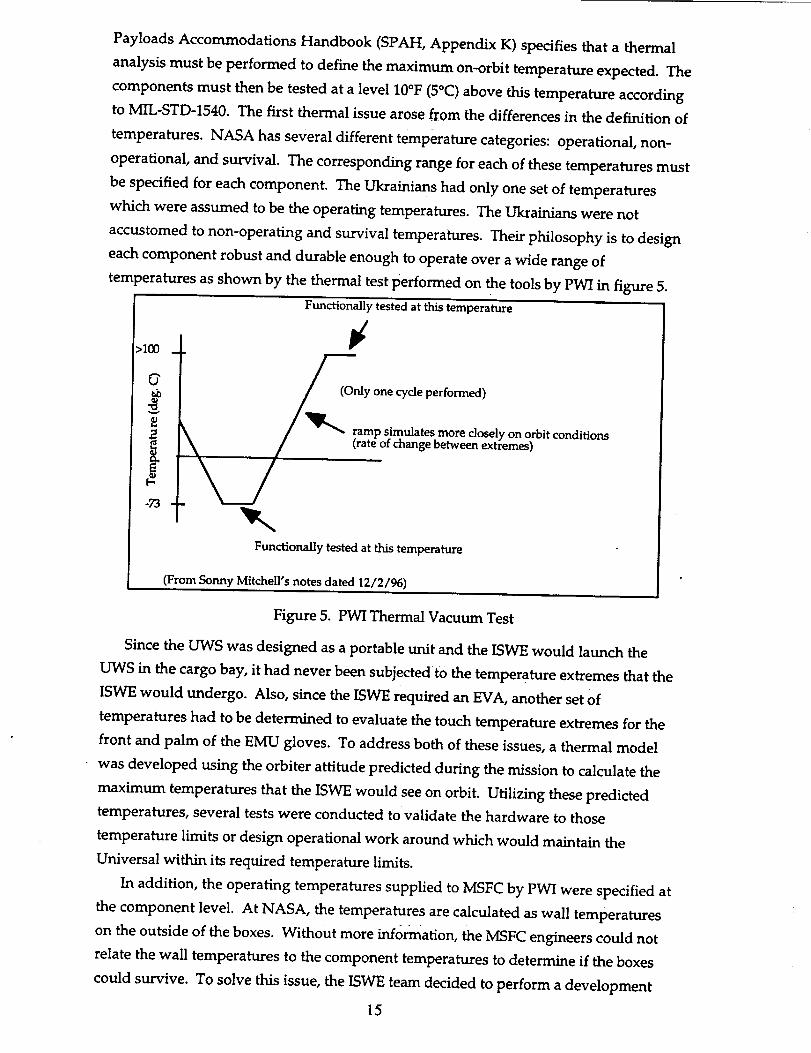
Payloads Accommodations Handbook (SPAH, Appendix K) specifies that a thermal
analysis must be performed to define the maximum on-orbit temperature expected. The
components must then be tested at a level 10°F (5°C) above this temperature according
to MIL-STD-1540. The first thermal issue arose from the differences in the definition of
temperatures. NASA has several different temperature categories: operational, non-
operational, and survival. The corresponding range for each of these temperatures must
be specified for each component. The Ukrainians had only one set of temperatures
which were assumed to be the operating temperatures. The Ukrainians were not
accustomed to non-operating and survival temperatures. Their philosophy is to design
each component robust and durable enough to operate over a wide range of
tern _eratures as shown by the thermal test performed on the tools by PWI in figure 5.
Functionally tested at this temperature
>IO0
A_J
o_ y one cycle performed)
i . _ _raamP simulates more closely on orbit condition s
m
-73
Functionally tested at this temperature
(From Sonny Mitchell's notes dated 12/2/96)
Figure 5. PWI Thermal Vacuum Test
Since the UWS was designed as a portable unit and the ISWE would launch the
UWS in the cargo bay, it had never been subjected to the temperature extremes that the
ISWE would undergo. Also, since the ISWE required an EVA, another set of
temperatures had to be determined to evaluate the touch temperature extremes for the
front and palm of the EMU gloves. To address both of these issues, a thermal model
was developed using the orbiter attitude predicted during the mission to calculate the
maximum temperatures that the ISWE would see on orbit. Utilizing these predicted
temperatures, several tests were conducted to validate the hardware to those
temperature limits or design operational work around which would maintain the
Universal within its required temperature limits.
In addition, the operating temperatures supplied to MSFC by PWI were specified at
the component level. At NASA, the temperatures are calculated as wall temperatures
on the outside of the boxes. Without more information, the MSFC engineers could not
relate the wall temperatures to the component temperatures to determine if the boxes
could survive. To solve this issue, the ISWE team decided to perform a development
15

test on the PWI hardware to determine the relationship between the wall and component
temperatures. In addition to the developmental tests, the PWI hardware will undergo
several other thermal tests as depicted in figure 6.
Thermal Cycle Test Thermal Cycle Test
Thermal Vacuum Test Thermal Vacuum Test
Thermal Mechanisms Test
Figure 6. Thermal Tests
As one can see from figure 6, the hand tools undergo two separate thermal tests;
thermal cycle and thermal vacuum. The first test is designed as a check or screening
before the thermal vacuum test to pinpoint any workmanship problems in the design.
The Ukrainians believed that twenty-four cycles in the thermal cycle test and eight cycles
in the thermal vacuum test were too much on the tools. This issue brought forth another
example of a fundamental difference in each institution's testing philosophy. The PWI
subjected the tools to one" thermal vacuum cycle, taking the tools to their temperature
extremes and functioning them (figure 5) This thermal testing is in accordance with the
guidelines established by Energia, the Russian Space Station M/R contractor, to qualify
equipment to fly on the MIR (Sonny Mitchell's notes, December 2, 1996). However,
NASA/MSFC adopted a different philosophy. Instead of taking the tools to an extreme
temperature, the tools were subjected to the maximum expected on orbit temperatures
plus 5 °C margin. They were then cycled twenty-four times at the fastest possible ramp
rate (Figure 7). It was felt that the thermal cycle test would clearly point out any defects
in the hardware before the expensive and complicated thermal vacuum test. This
16

relativelysmalldifferencein thermaltesting philosophy resulted in a significant issue of
concern.
70 w
v
EQ./
-39
Dwell _ temperature for 1 hour after hardware stabilizes
tinued for total of 24 cycles)
_Ramp rate of chamber to be as fast as possible
Dwell at this temperature for 1 hour after hardware stabilizes
(From ISWE Test Procedure MTCP-FC-ISWE-301)
Figure 7. MSFC Thermal Cycle Tool Test
Test Procedures
To test and qualify a piece of hardware at MSFC, a procedure must be written to
document the work to be done by a qualified test engineer. ISWE's hardware had to
undergo this type of plan as well. A discrepancy was discovered during conversations
between the MSFC test engineers and the PWI engineers. At MSFC if a piece of
hardware must be changed out or reconfigured for another test, a procedure must be
written to do that hardware change. If this is notwritten and the change is made, all
prior tests done are invalid because the flight hardware configuration has been altered.
In the case of ISWE, there were four such instances.
1) The cathode inside the UWS can be used up during the qualification tests and might
need to be removed and a new one installed. Each cathode has a useful life of one hour
and their are two cathodes per tool.
2) The filler wire inside the Filler Wire Tool might need to be changed or a new wire
added.
3) The Coating Tool's crucibles and turret head might have to be removed and a new
one installed.
4) The Technological Block would possibly need to be re-pressurized at Kennedy Space
Center (KSC) or MSFC.
When the Ukrainians test their hardware and a part has to be changed they add a
line to the test procedure saying that one of the engineers will change the part. No
documented procedure on how to change the part was written. PWI had never
documented these procedures before. Only standardized, documented procedures
17

provide alevel of assurance.After somediscussionwith PWI aboutthis issue,they
agreedto documenttheir procedures for these four events.
Section 4: Safety
Risk is inherent in any space venture. When man is involved in the venture, the
safety measures required to mitigate the risk increase tremendously. Within NASA, a
Payload Safety Review Panel (PSRP) managed by the Johnson Space Center (JSC) in
Houston, Texas oversees every project's safety compliance to fly on board the shuttle.
This panel reviews the project's safety with respect to NASA requirements and provides
feedback to the project team to help them comply. This panel meets at different times
during the payload's development cycle to ensure a safe flight system is being prepared.
These meetings are a Phase 0/1 review, a Phase 2 review, and a Phase 3 review. With
ISWE being such a complex and potentially "hazardous" system, the safety panel met
several times during the Phase 0/1 review to completely identify the hazards and safety
controls of the ISWE. Figure 4 shows several meetings held by the safety panel during
ISWE's review process.
In contrast, in the Ukraine there is no independent safety review commission/board.
Payload specialists conduct their own reviews after which the final solutions are
presented to the State Committee. However, the lead safety role belongs to the general
designer. If he says yes to the risks, etc., then the whole issue is a go. The state
committee is called a "Final Safety Commission". It is essentially similar to the PSRP,
but less meticulous. Most of the discussions take place in working groups. Routinely,
the commission will have the "yes-no" approach to most problems. Normally, no more
than two to three questions for each topic are asked/answered during a session. The
meeting of the committee normally takes one day instead of many (Zagrebelnij, 1996).
Contamination
When an experiment is flown on the orbiter, certain precautions must be taken to
ensure the cleanliness and safety of the experiment. In the case of ISWE, the team had
to ensure that the ISWE would not contaminate the shuttle, the EVA crewman's suit, the
extra vehicular mobility unit (EMU), or other payloads. Unlike the previous missions of
the UWS, ISWE welded more samples and at a higher power mode, therefore, it was
expected that there would be more contamination than was experienced previously by
PWI.
To provide this contamination free environment, the ISWE team had to design and
manufacture several items necessary to ensure the cleanliness of the ISWE. When the
ISWE is in operation, particulates can develop that could contaminate the other
experiments in the cargo bay violating JA-081, "Payload Mission Manager Safety &
18

InterfaceRequirementsPartial Payload Missions". Contamination of other payloads
was not an issue to the Ukrainians because the system that flew on Salyut was mounted
to the side of the spacecraft and allowed to expel vapor into space. Contamination is
also important to the orbiter itself. If the shuttle's radiators become coated with
material, they will not be able to reject the heat produced from the shuttle's internal
systems causing an emergency de-orbit. Further, the aft flight deck windows would
become covered by the vapor deposition resulting in a safety concern for the crew. To
alleviate all of these concerns, a contamination curtain (CC) was designed and built byMSFC.
In addition, the EMU had to be protected from contamination. The EMU suits used
by NASA are not expendable and must be reused. Also, the EMU's sensors and life
support equipment are very sensitive and must be adequately protected to ensure the
safety of the astronaut. A welding cosmonaut aboard the Salyut was provided no such
suit protection (Zagrebelnij, 1996). After the welding operation, the suit was used again
after a damage inspection. NASA was still insistent that the EMU be protected. ]SC
devised an EMU protective garment that would prevent the EMU from becoming
contaminated. After the _welding is complete, the astronaut takes off the protective
garment and stows it in a garment stowage bag mounted on ISWE.
Further, the EMU helmet must continue to be contaminate free during welding
operations. To give the astronaut complete visibility of the weld pool expendable
shields had to be designed to cover the visor. Once the shield becomes too
contaminated for the astronaut to see, he will replace it with a clean one. When the
Russians welded on Salyut, the cosmonaut had no other means of protection other that
his helmet visor.
Light Intensity
Another hazard is associated with the weld pool being too intense for the
astronaut's eyes. As with normal welding operations on Earth, welding in space
requires eye protection from the intense light being emitted. If there is no protection
provided, the retina in the eye would become damaged, with a resultant possible loss of
sight. The standard cosmonaut's visor is made with a high optical density material to
prevent this from happening. During their welding operations, their sun visor was used
only when the titanium sample was being welded. This sun visor was also standard,
with gold plating. The American counterpart, however, is of less optical density. To
alleviate this problem a visor analysis was conducted to see if the sun visor provided on
the standard EMU would be sufficient. Per Dr. Martin E. Coleman's memo to Mr. Curt
Broussard, dated August 16, 1996, "...conduct of the ISWE in the space vacuum, while
wearing an EMU with the standard sun visor, will not present an eye hazard from the
bright light produced."
19

Theabovediscussionis aprime exampleof the issuesthat arise during technology
utilization. The system utilized was designed to meet another set of criteria and
requirements. Once subjected to new criteria and requirements, obvious discrepancies
occur, some of which may be quite serious. If the same standards were used, issues such
as the one above would be resolved in a matter of minutes instead of days, or never
Occur.
Section 5: What About ISO?
The International Organization for Standardization (ISO)
ISO is a worldwide federation of national standards bodies, at present
compromising 118 members, one in each country. The object of ISO is to promote the
development of standardization and related activities in the world with a view to
facilitate international exchange of goods and services, and to develop cooperation in
the spheres of intellectual, scientific, and technological and economic activity. The
results of ISO technical work are published as International Standards.
The scope of ISO covers standardization in all fields except electrical and electronic
engineering standards, which are the responsibility of the International Electrotechnical
Commission (IEC). ISO brings together the interests of producers, users (including
consumers), governments and the scientific community, in the preparation of
international standards.
ISO work is carried out through 2,856 technical bodies. More than 30,000 experts
from all parts of the world participate each year in the ISO technical work which, to
date, has resulted in the publication of 10,189 ISO standards.
ISO Standards and ISWE
Several of the issues encountered with ISWE would have been eliminated if ISO
standards had been in place at both MSFC and PWI. Concerns over manufacturing
processes, fastener strength and quality, and material property certification would have
been eliminated with adherence to ISO standards in section 49, Aircraft and Space
Vehicle Engineering. For example, Aluminum is the most common material used on
ISWE, section 49.025.20 deals specifically with Aluminum alloys, their inspection,
testing, and supply requirements, in aerospace construction. Section 49.030 of the ISO
standards deals with the integrity of each fastener manufactured and even describes the
process to test those fasteners. Adherence to this standard would have allowed for
easier approval of the PWI process for their fasteners.
20

Concernswith ISO
Although severalof thespecificissuesencounteredby ISWEwereunique,adherenceto ISOstandardswould havepotentially eliminatedmanyof themasconcerns.But
severalmembernations,mostnotably the United States, have not fully embraced ISO
jurisdiction in areas which would significantly impact its economic well-being. The first
reason for this stand is the fact that although the U.S. drives a significant amount of the
world's engineering activity, it has only a single vote among many in ISO decisions. Also,
the near term cost of fully implementing current ISO standards would easily cost billions
of dollars. Obviously, as engineering activity becomes more internationalized, especially
in space, the long terms gains of uniform standards (in terms of reduced cost and effort)must be considered.
Conclusion
The International Space Welding Experiment was designed and submitted in the
Fourth NASA Call for Flight Demons trationsl Although originally conceived to
demonstrate the capability of welding in space as a possible repair scenario. ISWE
became a larger demonstration of international space cooperation. Through ISWE, one-
time rivals, the United States and the Ukraine, have come together to share technologies
and lessons learned from three decades of flying in space. For many of the engineers at
NASA Marshall Space Hight Center as well as the Ukraine, the ISWE experience has
encouraged new ways of thinking and creative approaches to problem solving. But
through the entire process, all of the engineers have been surprised at how differently the
two parties operate. This shared learning experience can serve as an example of the
pitfalls and successes faced when creating a truly international space program.
The history of ISWE redesigns which developed out a lack of common standards
should serve as a catalyst for the development of a new set of standards. This process
should at least begin with the current major space powers; NASA, the Russian Space
Agency, the Japanese Space Agency (NASDA), and the unified European countries
through the European Space Agency (ESA), convening a conference to develop a truly
international set of standards for space technologies. Although NASA would normally
seek to lead such a process, the authors feel that each nation should be given equal
standing based on their cumulative years of experience. Standards should be assessed
based on objective engineering judgment and not the bias of past practice. Creation of
such a system would facilitate and promote future international partnerships and help
to make space exploration and exploitation a truly international endeavor.
21

References
Avduyevsky,V.S.,ed. Manufacturing in Space:Processing Problems and Advances.Moscow: MIR Publishers, (1985).
Clark, Tony. "Orbiter/EMU/USMP-4 Payload Payload-to-UHT ElectromagneticInterference (EMI)" RID# ISWE-0037, (March 17, 1995).
Clark, Tony. Email on EMI Sequence of Events, (March 13, 1997).
Denniston, Charles. "No Preload Indicated in Fastener Analysis" RID# ISWC-0030,
(September 15, 1995).
Denniston, Charles. "The Preload Requirement for Threaded Fasteners in the
International Space Welding Hardware" Letter ED 25 (95-xx), (October 14, 1995).
Finney, David and Gibson, Robert. "Crew Position on Extravehicular Activity PIP Pins."Letter CA3-92-005, (February 4, 1993).
Geurkink, Don. "Friction Type Launch Lock for Sliding Foot Restraint" RID#ISWC-0033, (September 15, 1995).
McIntyre, Tamara. "GOST Standards, Technical Specifications, and TechnicalRequirements" RID# ISWE-0022, (March 17, 1995).
McIntyre, Tamara. "Thermal Vacuum Bakeout of UHT Equipment located in ShuttleCargo Bay" RID# ISWE-0025, (March 17, 1995).
McIntyre, Tamara. "Ukrainian Power Cables" RID# ISWE-0016, (March 17, 1995).
Rainwater, Neil. Verification Requirements and Specifications Document. MSFC-RQMT-2532, (August 28, 1995).
Russell, Carolyn, et al. Science Requirements Document. (April 1996).
Zagrebelnij, Alexander. Response to Questions during the UHT Review. (February 28,
1995).
Zagrebelnij, Alexander. Conversation. (August 21, 1996).
22

ISWE:
APPROVAL
A Case Study of Technology Utilization
M.P. Benfield, D.P. Mitchell, M.T. Vanhooser, D.B. Landrum
The information in this report has been reviewed for technical content. Review of any information
concerning Department of Defense or nuclear energy activities or programs has been made by the MSFCSecurity Classification Officer. This report, in its entirety, has been determined to be unclassified.
Gabriel Wallace
Deputy Director, Systems Analysis and Integration Laboratory

REPORT DOCUMENTATION PAGE Form ApprovedOMB No. 0704-0188
Public re_oding burden for this collection of infom'laEon IS estimated to average 1 hour per re_oonse, including the time for reviewing instrucEons, searching existing data souro_,gathering and maintaining the data needed, and coming and reviewing the col_ of information. Send comments regarding this burden estimate or any other aspect of thiscot_ of information, includ_g suggestions for reducing this humbert,to Washington Headquadscs Ser_, Directorata for Informalion OperaEon and Repods, 1215 JeffecsonDavis Highway, Suite 1204, ArFmgton. VA 2220_-4302. and to the Office of Management and Bc_lget, Pape_ Reduction Project (0704-0188), Wa_ington, DC 20503
1. AGENCY USE ONLY (Leave B/ank) 2. REPORT DATE
March 19984. TITLE AND SUBTITLE
ISWE: A Case Study of Technology Utilization
6. AUTHORS
M.P. Benfield, D.P. Mitchell, M.T. Vanhooser, D.B. Landrum
7. PERFORMING ORGANIZATION NAMES(S) AND AODRESS(ES)
George C. Marshall Space Flight Center
Marshall Space Flight Center, Alabama 35812
9. SPONSORING/MONITORINGAGENCYNAME(S)ANDADDRESSEES)
National Aeronautics and Space Administration
Washington, DC 20546-0001
3. REPORT TYPE AND DATES COVERED
Technical Memorandum5. FUNDING NUMBERS
8. PERFORMING ORGANIZATION
REPORT NUMBER
M-845
10. SPONSORING/MONITORING
AGENCY REPORT NUMBER
NASA/TM-1998-206528
11. SUPPLEMENTARY NOTES
Prepared by Systems Analysis and Integration Laboratory, Science and EngineeringDirectorate
12_ _STRiBU_ONJAVA_LABa.rn'SrATEMEmUnclassified-Unlimited
Nonstandard Distribution
12b. DISTRIBUTION CODE
13. ABSTRACT (Maxirnum 200 words)
The International Space Welding Experiment is a joint project between the E.O. Paton
Welding Institute of Kiev, Ukraine and the George C. Marshall Space Flight Center in
Huntsville, Alabama. When an international parmer is involved in a project, differences in
design and testing philosophy can become a factor in the development of the hardware. This
report addresses selected issues that arose during the ISWE hardware development as wellas the solutions the ISWE team made.
14. SUBJECT TERMS
international standards, design philosophy, testing philosophy
t7. SECURITY CLASSIFICATION
OF REPORT
Unclassified
NSN 7540-01-280-5500
18. SECURITY CLASSIFICATIONOF THIS PAGE
Unclassified
19. SECURITY CLASSIFICATION
OF ABSTRACT
Unclassified
15. NUMBER OF PAGES
3216. PRICE CODE
A03
20. LIMITATION OF ABSTRACT
Unlimited
Standard Form 298 (Rev. 2-89)Pres_ibedby ANSI _d. 239-18298-102