Embed Size (px)
Citation preview
IT DEPARTMENT
SEMESTER IV
COMPUTER ORGANIZATION AND ARCHITECTURE
LABORATORY MANUAL
AS PER REVISED SYLLABUS
UNIVERSITY OF MUMBAI
ARMIET/IT/ DEGREE/ IV SEM / COA/ OF
LABORATORY MANUAL CONTENTS
This manual is intended for the Second year students
of Information Technology in the subject of Computer
Organization and Architecture. This manual typically
contains practical/Lab Sessions related COA covering
various aspects related to the subject to enhanced
understanding.
Although, as per the syllabus, study of Half Adder, Full
Adder etc. Computer Architecture is prescribed, we have
made the efforts to cover various aspects of COA covering
almost all the aspects to elaborative understandable
concepts and conceptual visualization.
Students are advised to thoroughly go though this
manual rather than only topics mentioned in the syllabus
as practical aspects are the key to understanding and
conceptual visualization of theoretical aspects covered in the
books.
Good Luck for your Enjoyable Laboratory Sessions
Mr. Likhesh Kolhe Mr. Mayank Mangal
HOD,IT Department Asst Prof, IT Department

ARMIET/IT/ DEGREE/ IV SEM / COA/ OF
Do’s and Don’ts in Laboratory:
1. Make entry in the Log Book as soon as you enter the Laboratory.
2. All the students should sit according to their roll
numbers starting from their left to right.
3. All the students are supposed to enter the terminal number in the
log book.
4. Do not change the terminal on which you are working.
5. All the students are expected to get at least the algorithm
of the program/concept to be implemented.
6. Strictly observe the instructions given by the teacher/Lab
Instructor.

ARMIET/IT/ DEGREE/ IV SEM / COA/ OF
Instruction for STUDENTS
1. Submission related to whatever lab work has been
completed should be done during the next lab session. The
immediate arrangements for printouts related to submission
on the day of practical assignments.
2. Students should be taught for taking the printouts
under the observation of lab teacher.
3. The promptness of submission should be encouraged by
way of marking and evaluation patterns.
ARMIET/IT/ DEGREE/ IV SEM / COA/ OF
COA LABORATORY
ACADEMIC YEAR 2014-2015
DEPARTMENT OF INFORMATION TECHNOLOGY
SUB: COPUTER ORGANIZATION AND ARCHITECTURE
Class: Second Year Sem: IV
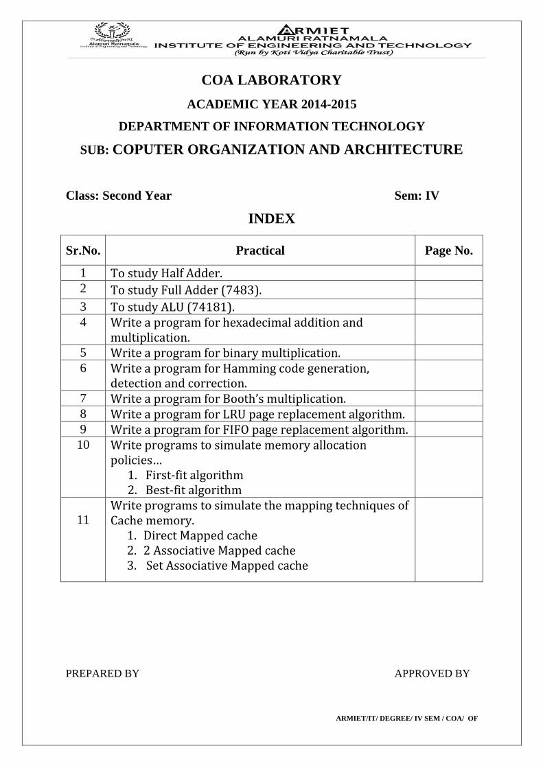
INDEX
Sr.No. Practical Page No.
1 To study Half Adder.
2 To study Full Adder (7483).
3 To study ALU (74181).
4 Write a program for hexadecimal addition and multiplication.
5 Write a program for binary multiplication.
6 Write a program for Hamming code generation, detection and correction.
7 Write a program for Booth’s multiplication.
8 Write a program for LRU page replacement algorithm.
9 Write a program for FIFO page replacement algorithm.
10
Write programs to simulate memory allocation policies… 1. First-fit algorithm 2. Best-fit algorithm
11 Write programs to simulate the mapping techniques of Cache memory.
1. Direct Mapped cache 2. 2 Associative Mapped cache 3. Set Associative Mapped cache
PREPARED BY APPROVED BY
ARMIET/IT/ DEGREE/ IV SEM / COA/ OF
EXPERIMENT NO:1 DOP: DOS: GRADE:
TITLE OF EXPERIMENT: HALF ADDER
AIM: TO STUDY HALF ADDER
AIM: To study Half Adder. THEORY: To understand what is a half adder you need to know what is an adder first. Adder circuit is a combinational digital circuit that is used for adding two numbers. A typical adder circuit produces a sum bit (denoted by S) and a carry bit (denoted by C) as the output. Typically adders are realized for adding binary numbers but they can be also realized for adding other formats like BCD (binary coded decimal, XS-3 etc. Besides addition, adder circuits can be used for a lot of other applications in digital electronics like address decoding, table index calculation etc. Adder circuits are of two types:
1. Half adder
2. Full adder.
Half adder circuit:
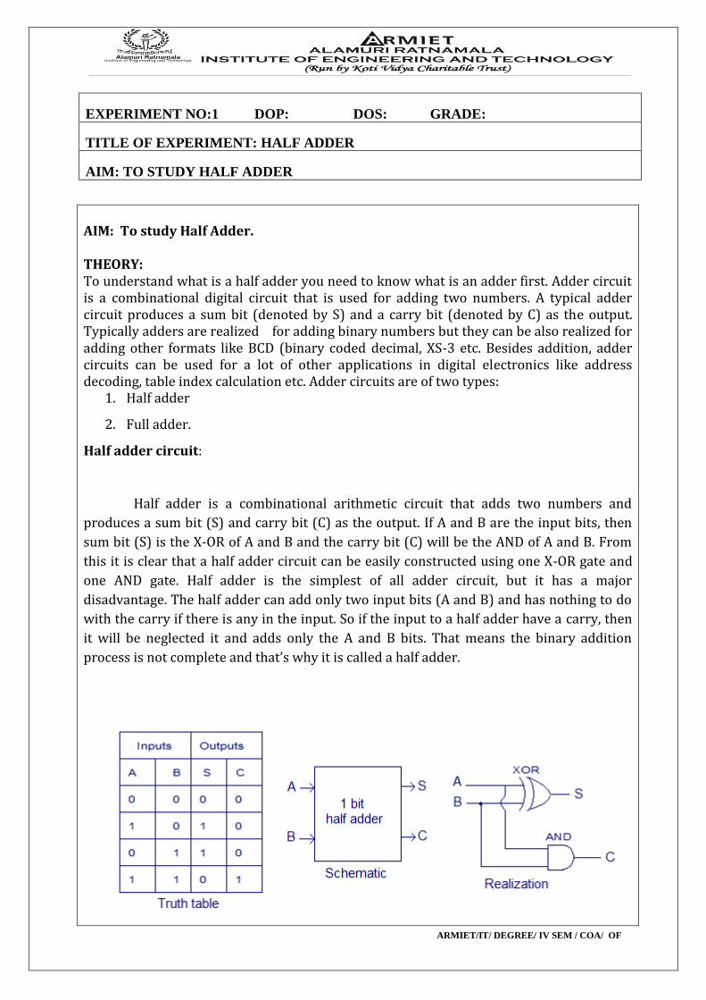
Half adder is a combinational arithmetic circuit that adds two numbers and
produces a sum bit (S) and carry bit (C) as the output. If A and B are the input bits, then
sum bit (S) is the X-OR of A and B and the carry bit (C) will be the AND of A and B. From
this it is clear that a half adder circuit can be easily constructed using one X-OR gate and
one AND gate. Half adder is the simplest of all adder circuit, but it has a major
disadvantage. The half adder can add only two input bits (A and B) and has nothing to do
with the carry if there is any in the input. So if the input to a half adder have a carry, then
it will be neglected it and adds only the A and B bits. That means the binary addition
process is not complete and that’s why it is called a half adder.
ARMIET/IT/ DEGREE/ IV SEM / COA/ OF
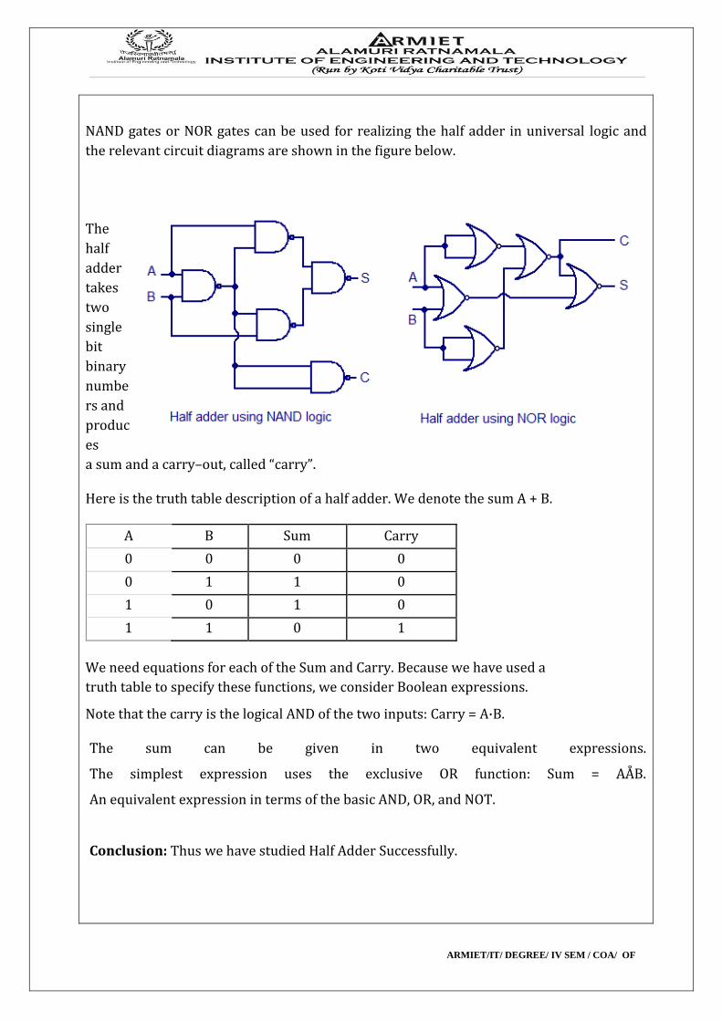
NAND gates or NOR gates can be used for realizing the half adder in universal logic and
the relevant circuit diagrams are shown in the figure below.
The
half
adder
takes
two
single
bit
binary
numbe
rs and
produc
es
a sum and a carry–out, called “carry”.
Here is the truth table description of a half adder. We denote the sum A + B.
A B Sum Carry
0 0 0 0
0 1 1 0
1 0 1 0
1 1 0 1
We need equations for each of the Sum and Carry. Because we have used a
truth table to specify these functions, we consider Boolean expressions.
Note that the carry is the logical AND of the two inputs: Carry = A·B.
The sum can be given in two equivalent expressions.
The simplest expression uses the exclusive OR function: Sum = AÅB.
An equivalent expression in terms of the basic AND, OR, and NOT.
Conclusion: Thus we have studied Half Adder Successfully.
ARMIET/IT/ DEGREE/ IV SEM / COA/ OF
EXPERIMENT NO:2 DOP: DOS: GRADE:
TITLE OF EXPERIMENT: FULL ADDER(7483)
AIM: TO STUDY FULL ADDER(7483)
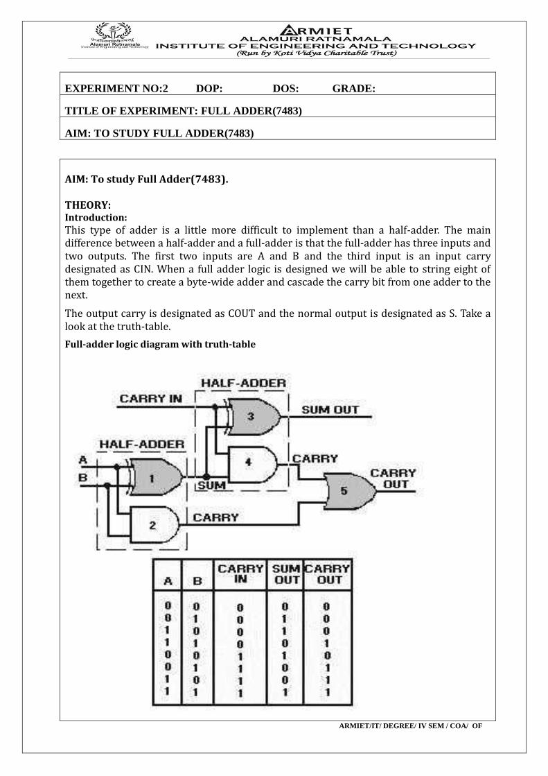
AIM: To study Full Adder(7483). THEORY: Introduction: This type of adder is a little more difficult to implement than a half-adder. The main difference between a half-adder and a full-adder is that the full-adder has three inputs and two outputs. The first two inputs are A and B and the third input is an input carry designated as CIN. When a full adder logic is designed we will be able to string eight of them together to create a byte-wide adder and cascade the carry bit from one adder to the next.
The output carry is designated as COUT and the normal output is designated as S. Take a look at the truth-table. Full-adder logic diagram with truth-table

ARMIET/IT/ DEGREE/ IV SEM / COA/ OF
From the above truth-table, the full adder logic can be implemented. We can see that the output S is an EXOR between the input A and the half-adder SUM output with B and CIN inputs. We must also note that the COUT will only be true if any of the two inputs out of the three are HIGH.
Thus, we can implement a full adder circuit with the help of two half adder circuits. The first will half adder will be used to add A and B to produce a partial Sum. The second half adder logic can be used to add CIN to the Sum produced by the first half adder to get the final S output. If any of the half adder logic produces a carry, there will be an output carry. Thus, COUT will be an OR function of the half-adder Carry outputs. Take a look at the implementation of the full adder circuit shown below.
Conclusion: Thus we have studied Full Adder(7483) Successfully.
ARMIET/IT/ DEGREE/ IV SEM / COA/ OF
EXPERIMENT NO:3 DOP: DOS: GRADE:
TITLE OF EXPERIMENT: ALU(74181)
AIM: TO STUDY ALU(74181)
AIM: To study the ALU(74181). THEORY: Introduction: Arithmetic Logic Unit: In digital electronics, an arithmetic and logic unit (ALU) is a digital circuit that performs
integerarithmetic and logical operations. The ALU is a fundamental building block of the central
processing unit of a computer, and even the simplest microprocessors contain one for purposes
such as maintaining timers. The processors found inside modern CPUs and graphics processing
units (GPUs) accommodate very powerful and very complex ALUs; a single component may
contain a number of ALUs.
Mathematician John von Neumann proposed the ALU concept in 1945, when he wrote a
report on the foundations for a new computer called the EDVAC.
The inputs to the ALU are the data to be operated on (called operands) and a code from
the control unit indicating which operation to perform. Its output is the result of the computation.
One thing designers must keep in mind is whether the ALU will operate on big-endian or little-
endian numbers.In many designs, the ALU also takes or generates inputs or outputs a set of
condition codes from or to a status register. These codes are used to indicate cases such as carry-in
or carry-out, overflow, divide-by-zero, etc.
A floating-point unit also performs arithmetic operations between two values, but
they do so for numbers in floating-point representation, which is much more complicated than the
two's complement representation used in a typical ALU. In order to do these calculations, a FPU
has several complex circuits built-in, including some internal ALUs.
In modern practice, engineers typically refer to the ALU as the circuit that performs
integer arithmetic operations (like two's complement and BCD). Circuits that calculate more
complex formats like floating point, complex numbers, etc. usually receive a more specific name
such as floating-point unit (FPU).
Steps : Conclusion: Thus we have studied ALU Successfully.
ARMIET/IT/ DEGREE/ IV SEM / COA/ OF
EXPERIMENT NO:4 DOP: DOS: GRADE:
TITLE OF EXPERIMENT: HEXADECIMAL ADDITION AND MULTIPLICATION
AIM: WRITE A PROGRAM FOR H. A. & M.
AIM: Write a program for hexadecimal addition and multiplication. THEORY: Introduction: Program Code: # include <iostream.h> # include <c.type.h> #include<string.h> Class Hexnumber { Int data[15]; Int n; Public: Hexnumber() {n=0;} Void read(); Void print(); Void leftshift(int count); Friend hexa number add(hexanumber,hexanumber); Friend hexanumber multiply(hexanumber,hexanumber) }; Void hexnumber::left shift(int count) { n=n+count for(;count>0;count--) data[n+count-1]=0; } Void hexnumber::read() { Char a[10]; Int i ; Cin>> a; For(i=0;a[i]!=’\0’;i++) { If(isdigit(a[i])) data[i]=a[i] & 0xf; else data[i]=(a[i] & 0xf) + 9; } n=i } Void hexnumber::print()
ARMIET/IT/ DEGREE/ IV SEM / COA/ OF
{ int i; for(i=0;i<n;i++0 if(data[i]<=9) count<<data[i]; else count<<(char)(data[i]+55); } Hexnumber add(hexnumber a, hexnumber b) { hexnumber c; int I,j,k,digita,digitb,carry=0; i=a,n-1; j=b,n-1; if(a,n>b,n) k=a,n; else k=b,n; c,n=k+1; for(;i>=0 || j>=0;i--,j--,k--) { digita=digitb=0; if(i>=0) digita=a, data[i]; if(j>=0) digitb=b,data[j]; c.data[k]=(carry+digita+digitb)%16; carry=(carry+digita+digitb)/16; } c.data[k]=carry; return(c); } Hexnumber multiply(hexnumber x, hexnumber y) { Hexnumber z, temp; int n; int count=0,product,carry=0,i,j,digit; for(i=y,n-1;i>=0;i--) { digit=y,data[i]; for(j=x,n-1;j>=0;j--) { Product=digit*x.data[j]+carry; Temp.data[j+1]-product%16; Carry=product/16; } Temp.data[j+1]=carry; Temp,n=x,n+1; Temp.leftshift(count); Count++; Z=add(z,temp); } return z;
ARMIET/IT/ DEGREE/ IV SEM / COA/ OF
} Voidmain() { Hexnumber a,b,c; Count<<”\n Enter first hex numbers ;”; a.read(); count<<”\n Enter second hex numbers ;”; b.read(); c=add(a,b); count<<”/nSum=”; c.print(); count<<”/nProduct=”; c=multiply(a,b); c.print(); } Output: Enter first hex numbers : 1d Enter second hex numbers : 5 Sum=022
ARMIET/IT/ DEGREE/ IV SEM / COA/ OF
EXPERIMENT NO:5 DOP: DOS: GRADE:
TITLE OF EXPERIMENT: BINARY MULTIPLICATION
AIM: WRITE A PROGRAM FOR BM
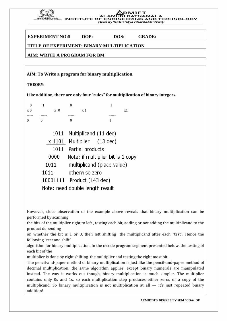
AIM: To Write a program for binary multiplication. THEORY: Like addition, there are only four "rules" for multiplication of binary integers.
0 1 0 1
x 0 x 0 x 1 x1
----- ----- ----- -----
0 0 0 1
However, close observation of the example above reveals that binary multiplication can be
performed by scanning
the bits of the multiplier right to left , testing each bit, adding or not adding the multiplicand to the
product depending
on whether the bit is 1 or 0, then left shifting the multiplicand after each "test". Hence the
following "test and shift"
algorithm for binary multiplication. In the c-code program segment presented below, the testing of
each bit of the
multiplier is done by right shifting the multiplier and testing the right most bit.
The pencil-and-paper method of binary multiplication is just like the pencil-and-paper method of
decimal multiplication; the same algorithm applies, except binary numerals are manipulated
instead. The way it works out though, binary multiplication is much simpler. The multiplier
contains only 0s and 1s, so each multiplication step produces either zeros or a copy of the
multiplicand. So binary multiplication is not multiplication at all — it’s just repeated binary
addition!
ARMIET/IT/ DEGREE/ IV SEM / COA/ OF
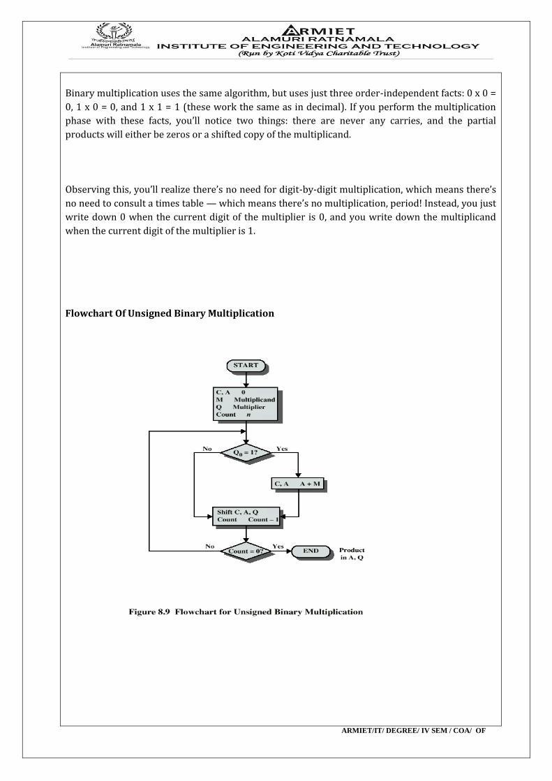
Binary multiplication uses the same algorithm, but uses just three order-independent facts: 0 x 0 =
0, 1 x 0 = 0, and 1 x 1 = 1 (these work the same as in decimal). If you perform the multiplication
phase with these facts, you’ll notice two things: there are never any carries, and the partial
products will either be zeros or a shifted copy of the multiplicand.
Observing this, you’ll realize there’s no need for digit-by-digit multiplication, which means there’s
no need to consult a times table — which means there’s no multiplication, period! Instead, you just
write down 0 when the current digit of the multiplier is 0, and you write down the multiplicand
when the current digit of the multiplier is 1.
Flowchart Of Unsigned Binary Multiplication
ARMIET/IT/ DEGREE/ IV SEM / COA/ OF
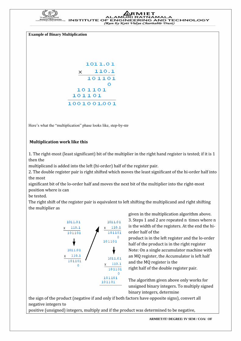
Example of Binary Multiplication
Here’s what the “multiplication” phase looks like, step-by-ste
Multiplication work like this
1. The right-most (least significant) bit of the multiplier in the right hand register is tested; if it is 1
then the
multiplicand is added into the left (hi-order) half of the register pair.
2. The double register pair is right shifted which moves the least significant of the hi-order half into
the most
significant bit of the lo-order half and moves the next bit of the multiplier into the right-most
position where is can
be tested.
The right shift of the register pair is equivalent to left shifting the multiplicand and right shifting
the multiplier as
given in the multiplication algorithm above.
3. Steps 1 and 2 are repeated n times where n
is the width of the registers. At the end the hi-
order half of the
product is in the left register and the lo-order
half of the product is in the right register
Note: On a single accumulator machine with
an MQ register, the Accumulator is left half
and the MQ register is the
right half of the double register pair.
The algorithm given above only works for
unsigned binary integers. To multiply signed
binary integers, determine
the sign of the product (negative if and only if both factors have opposite signs), convert all
negative integers to
positive (unsigned) integers, multiply and if the product was determined to be negative,
ARMIET/IT/ DEGREE/ IV SEM / COA/ OF
"complement and add one"
to make the product negative. With n-bit two's complement representation, the above algorithm
also works if the
multiplier is positive; the multiplicand can be positive or negative.
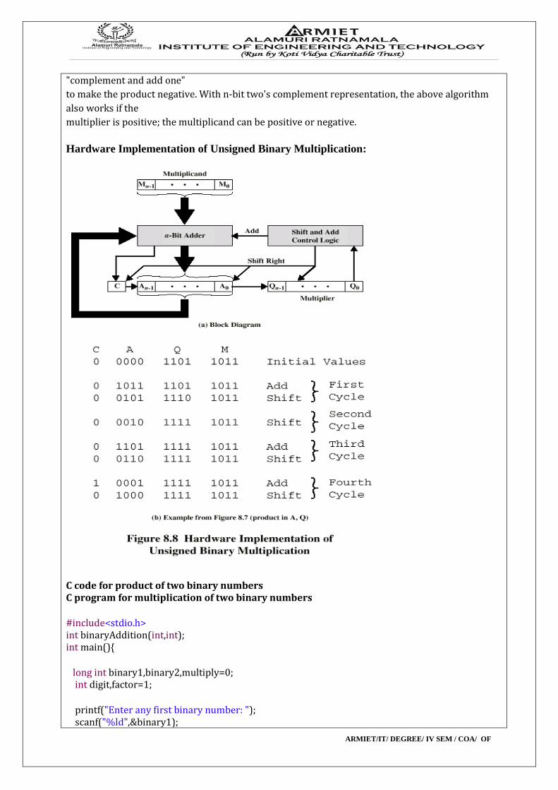
Hardware Implementation of Unsigned Binary Multiplication:
C code for product of two binary numbers C program for multiplication of two binary numbers #include<stdio.h> int binaryAddition(int,int); int main(){ long int binary1,binary2,multiply=0; int digit,factor=1; printf("Enter any first binary number: "); scanf("%ld",&binary1);
ARMIET/IT/ DEGREE/ IV SEM / COA/ OF
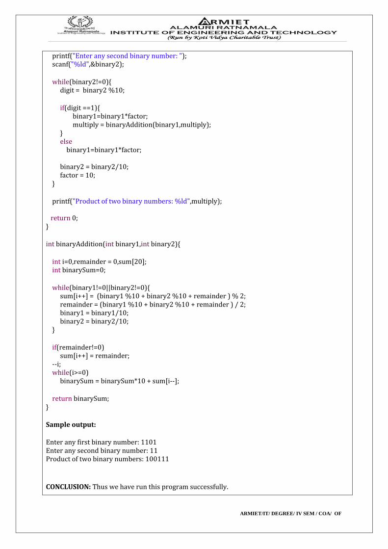
printf("Enter any second binary number: "); scanf("%ld",&binary2); while(binary2!=0){ digit = binary2 %10; if(digit ==1){ binary1=binary1*factor; multiply = binaryAddition(binary1,multiply); } else binary1=binary1*factor; binary2 = binary2/10; factor = 10; } printf("Product of two binary numbers: %ld",multiply); return 0; } int binaryAddition(int binary1,int binary2){ int i=0,remainder = 0,sum[20]; int binarySum=0; while(binary1!=0||binary2!=0){ sum[i++] = (binary1 %10 + binary2 %10 + remainder ) % 2; remainder = (binary1 %10 + binary2 %10 + remainder ) / 2; binary1 = binary1/10; binary2 = binary2/10; } if(remainder!=0) sum[i++] = remainder; --i; while(i>=0) binarySum = binarySum*10 + sum[i--]; return binarySum; } Sample output: Enter any first binary number: 1101 Enter any second binary number: 11 Product of two binary numbers: 100111
CONCLUSION: Thus we have run this program successfully.
ARMIET/IT/ DEGREE/ IV SEM / COA/ OF
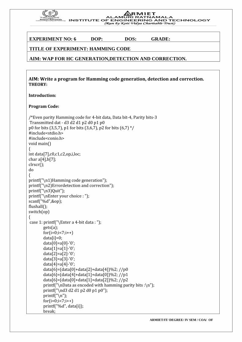
EXPERIMENT NO: 6 DOP: DOS: GRADE:
TITLE OF EXPERIMENT: HAMMING CODE
AIM: WAP FOR HC GENERATION,DETECTION AND CORRECTION.
AIM: Write a program for Hamming code generation, detection and correction. THEORY: Introduction: Program Code: /*Even parity Hamming code for 4-bit data, Data bit-4, Parity bits-3 Transmitted dat - d3 d2 d1 p2 d0 p1 p0 p0 for bits (3,5,7), p1 for bits (3,6,7), p2 for bits (6,7) */ #include<stdio.h> #include<conio.h> void main() { int data[7],c0,c1,c2,op,i,loc; char a[4],b[7]; clrscr(); do { printf("\n1)Hamming code generation"); printf("\n2)Errordetection and correction"); printf("\n3)Quit"); printf("\nEnter your choice : "); scanf("%d",&op); flushall(); switch(op) { case 1: printf("\Enter a 4-bit data : "); gets(a); for(i=0;i<7;i++) data[i]=0; data[0]=a[0]-'0'; data[1]=a[1]-'0'; data[2]=a[2]-'0'; data[3]=a[3]-'0'; data[4]=a[4]-'0'; data[6]=(data[0]+data[2]+data[4])%2; //p0 data[6]=(data[4]+data[1]+data[0])%2; //p1 data[6]=(data[0]+data[1]+data[2])%2; //p2 printf("\nData as encoded with hamming parity bits :\n"); printf("\nd3 d2 d1 p2 d0 p1 p0"); printf("\n"); for(i=0;i<7;i++) printf("%d", data[i]); break;
ARMIET/IT/ DEGREE/ IV SEM / COA/ OF
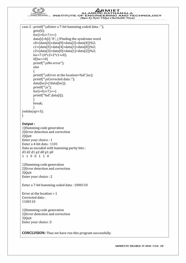
case 2 : printf("\nEnter a 7-bit hamming coded data : "); gets(b); for(i=0;i<7;i++) data[i]=b[i]-'0'; //Finding the syndrome word c0=(data[6]+data[0]+data[2]+data[4])%2; c1=(data[5]+data[4]+data[1]+data[0])%2; c2=(data[3]+data[0]+data[1]+data[2])%2; loc=7-(4*c2+2*c1+c0); if(loc==0) printf("\nNo error"); else { printf("\nError at the location=%d",loc); printf("\nCorrected data :"); data[loc]=(!data[loc]); printf("\n"); for(i=0;i<7;i++) printf("%d",data[i]); } break; } }while(op!=3); } Output : 1)Hamming code generation 2)Error detection and correction 3)Quit Enter your choice : 1 Enter a 4-bit data : 1101 Data as encoded with hamming parity bits : d3 d2 d1 p2 d0 p1 p0 1 1 0 0 1 1 0 1)Hamming code generation 2)Error detection and correction 3)Quit Enter your choice : 2 Enter a 7-bit hamming coded data : 1000110 Error at the location = 1 Corrected data : 1100110 1)Hamming code generation 2)Error detection and correction 3)Quit Enter your choice :3
CONCLUSION: Thus we have run this program successfully.
ARMIET/IT/ DEGREE/ IV SEM / COA/ OF
EXPERIMENT NO:7 DOP: DOS: GRADE:
TITLE OF EXPERIMENT: BOOTH’S MULTIPLICATION
AIM: WAP FOR BOOTH’S MULTIPLICATION
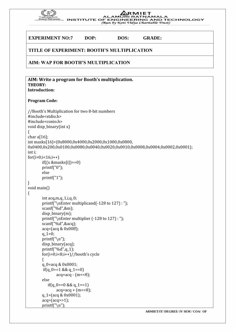
AIM: Write a program for Booth’s multiplication. THEORY: Introduction: Program Code: //Booth's Multiplication for two 8-bit numbers #include<stdio.h> #include<conio.h> void disp_binary(int x) { char a[16]; int masks[16]={0x8000,0x4000,0x2000,0x1000,0x0800, 0x0400,0x200,0x0100,0x0080,0x0040,0x0020,0x0010,0x0008,0x0004,0x0002,0x0001}; int i; for(i=0;i<16;i++) if((x &masks[i])==0) printf("0"); else printf("1"); } void main() { int acq,m,q_1,i,q_0; printf("\nEnter multiplicand(-128 to 127) : "); scanf("%d",&m); disp_binary(m); printf("\nEnter multiplier (-128 to 127) : "); scanf("%d",&acq); acq=(acq & 0x00ff); q_1=0; printf("\n"); disp_binary(acq); printf("%d",q_1); for(i=0;i<8;i++)//booth's cycle { q_0=acq & 0x0001; if(q_0==1 && q_1==0) acq=acq - (m<<8); else if(q_0==0 && q_1==1) acq=acq + (m<<8); q_1=(acq & 0x0001); acq=(acq>>1); printf("\n");
ARMIET/IT/ DEGREE/ IV SEM / COA/ OF
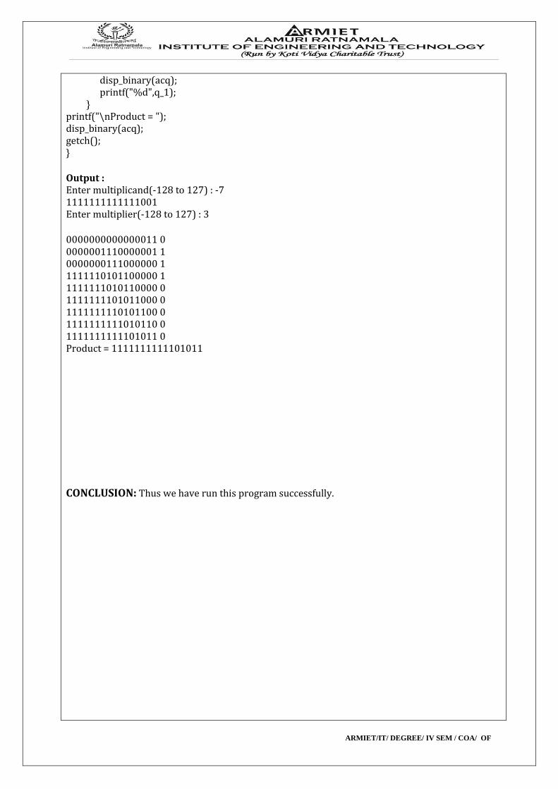
disp_binary(acq); printf("%d",q_1); } printf("\nProduct = "); disp_binary(acq); getch(); } Output : Enter multiplicand(-128 to 127) : -7 1111111111111001 Enter multiplier(-128 to 127) : 3 0000000000000011 0 0000001110000001 1 0000000111000000 1 1111110101100000 1 1111111010110000 0 1111111101011000 0 1111111110101100 0 1111111111010110 0 1111111111101011 0 Product = 1111111111101011 CONCLUSION: Thus we have run this program successfully.

ARMIET/IT/ DEGREE/ IV SEM / COA/ OF
EXPERIMENT NO:8 DOP: DOS: GRADE:
TITLE OF EXPERIMENT: FIFO PAGE REPLACEMENT ALGO
AIM: WAP FOR FIFO PR ALGO
AIM: Write a program for FIFO page replacement algorithm. THEORY: This article is about FIFOs in computing and electronic design. For the term in accounting, see FIFO and LIFO accounting. For the employment method, see Fly-in fly-out. FIFO is an acronym for First In, First Out, a method for organizing and manipulating a data buffer, or data stack, where the oldest entry, or 'bottom' of the stack, is processed first. It is analagous to processing a queue with first-come, first-served (FCFS) behaviour: where the people leave the queue in the order in which they arrive.
FCFS is also the jargon term for the FIFO operating system scheduling algorithm, which gives every process CPU time in the order in which it is demanded.
FIFO's opposite is LIFO, Last-In-First-Out, where the youngest entry or 'top of the stack' is processed first.
A priority queue is neither FIFO or LIFO but may adopt similar behaviour temporarily or by default.
Queueing theory encompasses these methods for processing data structures, as well as interactions between strict-FIFO queues.
FIFO full/empty
A hardware FIFO is used for synchronization purposes. It is often implemented as a circular queue, and thus has two pointers:
1. Read Pointer/Read Address Register 2. Write Pointer/Write Address Register
Read and write addresses are initially both at the first memory location and the FIFO queue is Empty.
FIFO Empty When the read address register reaches the write address register, the FIFO triggers the Empty signal.
FIFO FULL When the write address register reaches the read address register, the FIFO triggers the FULL signal.
In both cases, the read and write addresses end up being equal. To distinguish between the two situations, a simple and robust solution is to add one extra bit for each read and write address which is inverted each time the address wraps. With this set up, the conditions are:
FIFO Empty When the read address register equals the write address register, the FIFO is empty.
FIFO FULL When the read address LSBs equal the write address LSBs and the extra MSBs are different, the FIFO is full.
ARMIET/IT/ DEGREE/ IV SEM / COA/ OF
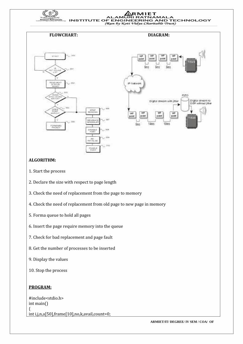
FLOWCHART: DIAGRAM:
ALGORITHM: 1. Start the process 2. Declare the size with respect to page length 3. Check the need of replacement from the page to memory 4. Check the need of replacement from old page to new page in memory 5. Forma queue to hold all pages 6. Insert the page require memory into the queue 7. Check for bad replacement and page fault 8. Get the number of processes to be inserted 9. Display the values 10. Stop the process PROGRAM: #include<stdio.h> int main() { int i,j,n,a[50],frame[10],no,k,avail,count=0;
ARMIET/IT/ DEGREE/ IV SEM / COA/ OF
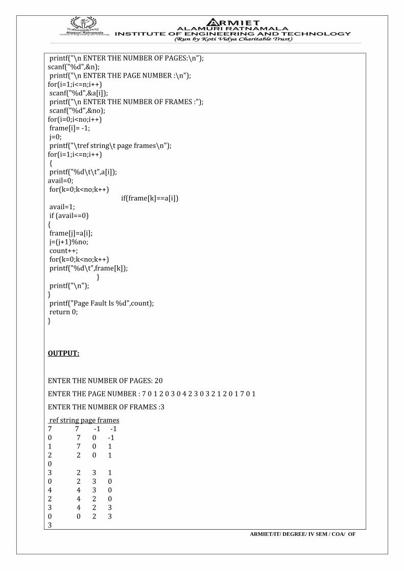
printf("\n ENTER THE NUMBER OF PAGES:\n"); scanf("%d",&n); printf("\n ENTER THE PAGE NUMBER :\n"); for(i=1;i<=n;i++) scanf("%d",&a[i]); printf("\n ENTER THE NUMBER OF FRAMES :"); scanf("%d",&no); for(i=0;i<no;i++) frame[i]= -1; j=0; printf("\tref string\t page frames\n"); for(i=1;i<=n;i++) { printf("%d\t\t",a[i]); avail=0; for(k=0;k<no;k++)
if(frame[k]==a[i]) avail=1; if (avail==0) { frame[j]=a[i]; j=(j+1)%no; count++; for(k=0;k<no;k++) printf("%d\t",frame[k]);
} printf("\n"); } printf("Page Fault Is %d",count); return 0; }
OUTPUT:
ENTER THE NUMBER OF PAGES: 20
ENTER THE PAGE NUMBER : 7 0 1 2 0 3 0 4 2 3 0 3 2 1 2 0 1 7 0 1
ENTER THE NUMBER OF FRAMES :3
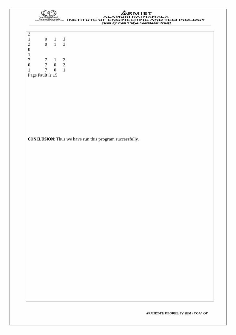
ref string page frames 7 7 -1 -1 0 7 0 -1 1 7 0 1 2 2 0 1 0 3 2 3 1 0 2 3 0 4 4 3 0 2 4 2 0 3 4 2 3 0 0 2 3 3
ARMIET/IT/ DEGREE/ IV SEM / COA/ OF
2 1 0 1 3 2 0 1 2 0 1 7 7 1 2 0 7 0 2 1 7 0 1 Page Fault Is 15
CONCLUSION: Thus we have run this program successfully.
ARMIET/IT/ DEGREE/ IV SEM / COA/ OF
EXPERIMENT NO: 9 DOP: DOS: GRADE:
TITLE OF EXPERIMENT: LRU
AIM: WAP FOR LRU PR ALGO
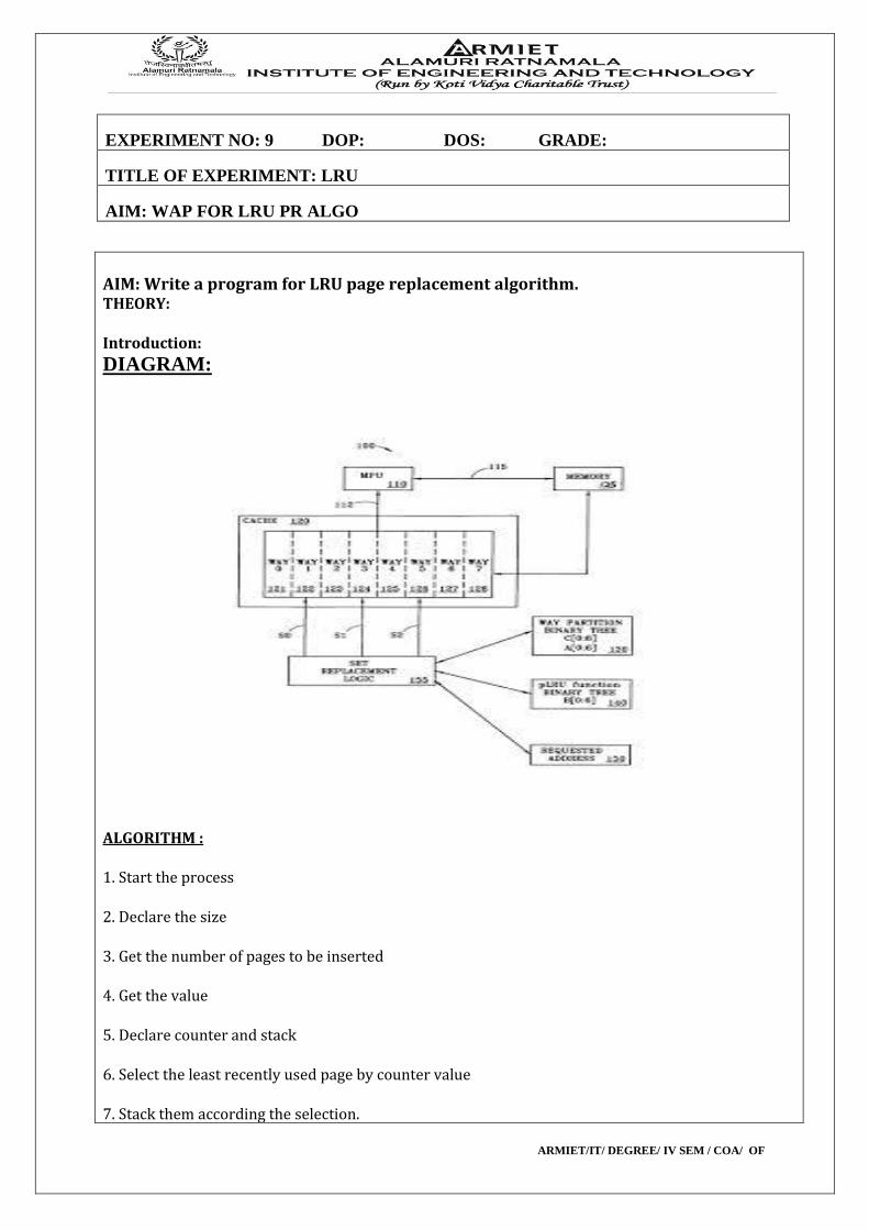
AIM: Write a program for LRU page replacement algorithm. THEORY: Introduction:
DIAGRAM:
ALGORITHM : 1. Start the process 2. Declare the size 3. Get the number of pages to be inserted 4. Get the value 5. Declare counter and stack 6. Select the least recently used page by counter value 7. Stack them according the selection.
ARMIET/IT/ DEGREE/ IV SEM / COA/ OF
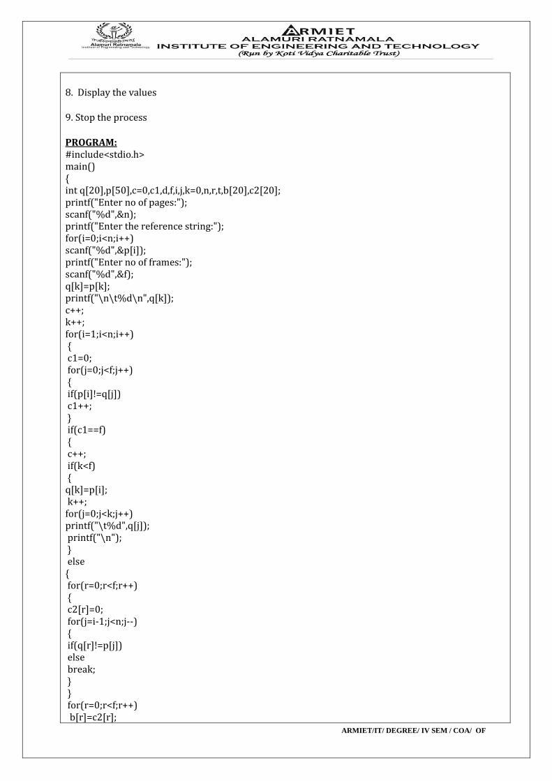
8. Display the values 9. Stop the process PROGRAM: #include<stdio.h> main() { int q[20],p[50],c=0,c1,d,f,i,j,k=0,n,r,t,b[20],c2[20]; printf("Enter no of pages:"); scanf("%d",&n); printf("Enter the reference string:"); for(i=0;i<n;i++) scanf("%d",&p[i]); printf("Enter no of frames:"); scanf("%d",&f); q[k]=p[k]; printf("\n\t%d\n",q[k]); c++; k++; for(i=1;i<n;i++) { c1=0; for(j=0;j<f;j++) { if(p[i]!=q[j]) c1++; } if(c1==f) { c++; if(k<f) { q[k]=p[i]; k++; for(j=0;j<k;j++) printf("\t%d",q[j]); printf("\n"); } else { for(r=0;r<f;r++) { c2[r]=0; for(j=i-1;j<n;j--) { if(q[r]!=p[j]) else break; } } for(r=0;r<f;r++) b[r]=c2[r];
ARMIET/IT/ DEGREE/ IV SEM / COA/ OF
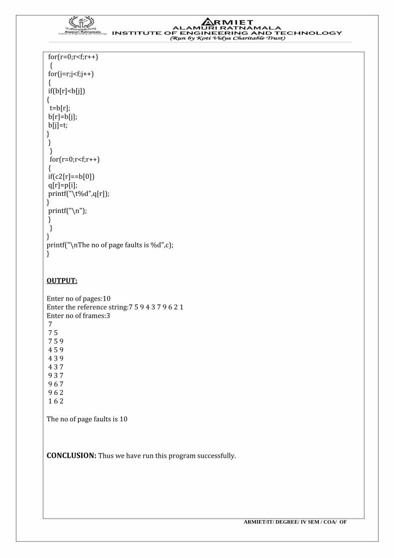
for(r=0;r<f;r++) { for(j=r;j<f;j++) { if(b[r]<b[j]) { t=b[r]; b[r]=b[j]; b[j]=t; } } } for(r=0;r<f;r++) { if(c2[r]==b[0]) q[r]=p[i]; printf("\t%d",q[r]); } printf("\n"); } } } printf("\nThe no of page faults is %d",c); } OUTPUT: Enter no of pages:10 Enter the reference string:7 5 9 4 3 7 9 6 2 1 Enter no of frames:3 7 7 5 7 5 9 4 5 9 4 3 9 4 3 7 9 3 7 9 6 7 9 6 2 1 6 2 The no of page faults is 10
CONCLUSION: Thus we have run this program successfully.
ARMIET/IT/ DEGREE/ IV SEM / COA/ OF
EXPERIMENT NO: 10 DOP: DOS: GRADE:
TITLE OF EXPERIMENT: MEMORY ALLOCATION
AIM: WAP TO SIMULATE MA POLICIES
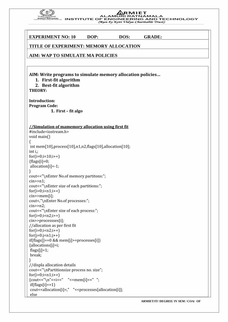
AIM: Write programs to simulate memory allocation policies… 1. First-fit algorithm 2. Best-fit algorithm THEORY: Introduction: Program Code:
1. First – fit algo //Simulation of mamemory allocation using first fit #include<iostream.h> void main() { int mem[10],process[10],n1,n2,flags[10],allocation[10]; int i,; for(i=0;i<10;i++) {flags[i]=0; allocation[i]=-1; } cout<<"\nEnter No.of memory partitons:"; cin>>n1; cout<<"\nEnter size of each partitions:"; for(i=0;i<n1;i++) cin>>mem[i]; cout<,"\nEnter No.of processes:"; cin>>n2; cout<<"\nEnter size of each process:"; for(i=0;i<n2;i++) cin>>processses[i]; //allocation as per first fit for(i=0;i<n2;i++) for(j=0;j<n1;j++) if(flags[]==0 && mem[j]>=processes[i]) {allocations[j]=i; flags[j]=1; break; } //displa allocation details cout<<"\nPartitionsize process no. size"; for(i=0;i<n1;i++) {cout<<"\n"<<i<<" "<<mem[i]<<" "; if(flags[i]==1) cout<<allocation[i]<," "<<processes[allocation[i]]; else
ARMIET/IT/ DEGREE/ IV SEM / COA/ OF
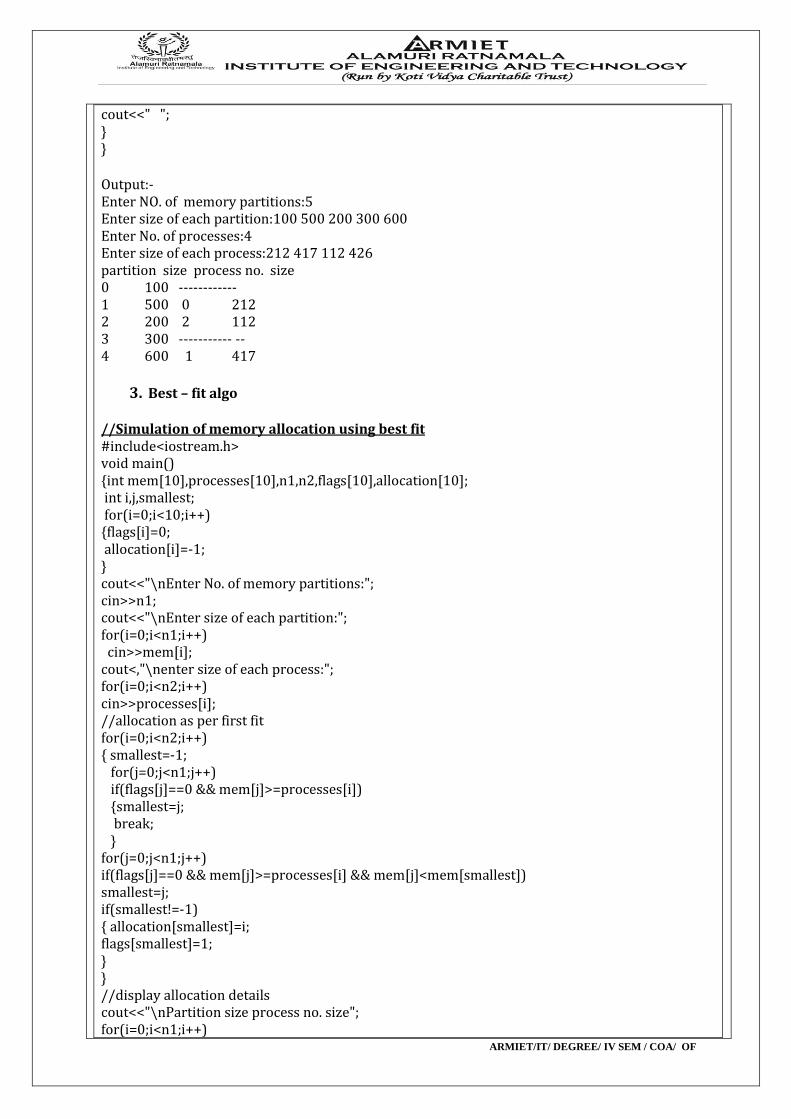
cout<<" "; } } Output:- Enter NO. of memory partitions:5 Enter size of each partition:100 500 200 300 600 Enter No. of processes:4 Enter size of each process:212 417 112 426 partition size process no. size 0 100 ------------ 1 500 0 212 2 200 2 112 3 300 ----------- -- 4 600 1 417
3. Best – fit algo //Simulation of memory allocation using best fit #include<iostream.h> void main() {int mem[10],processes[10],n1,n2,flags[10],allocation[10]; int i,j,smallest; for(i=0;i<10;i++) {flags[i]=0; allocation[i]=-1; } cout<<"\nEnter No. of memory partitions:"; cin>>n1; cout<<"\nEnter size of each partition:"; for(i=0;i<n1;i++) cin>>mem[i]; cout<,"\nenter size of each process:"; for(i=0;i<n2;i++) cin>>processes[i]; //allocation as per first fit for(i=0;i<n2;i++) { smallest=-1; for(j=0;j<n1;j++) if(flags[j]==0 && mem[j]>=processes[i]) {smallest=j; break; } for(j=0;j<n1;j++) if(flags[j]==0 && mem[j]>=processes[i] && mem[j]<mem[smallest]) smallest=j; if(smallest!=-1) { allocation[smallest]=i; flags[smallest]=1; } } //display allocation details cout<<"\nPartition size process no. size"; for(i=0;i<n1;i++)
ARMIET/IT/ DEGREE/ IV SEM / COA/ OF
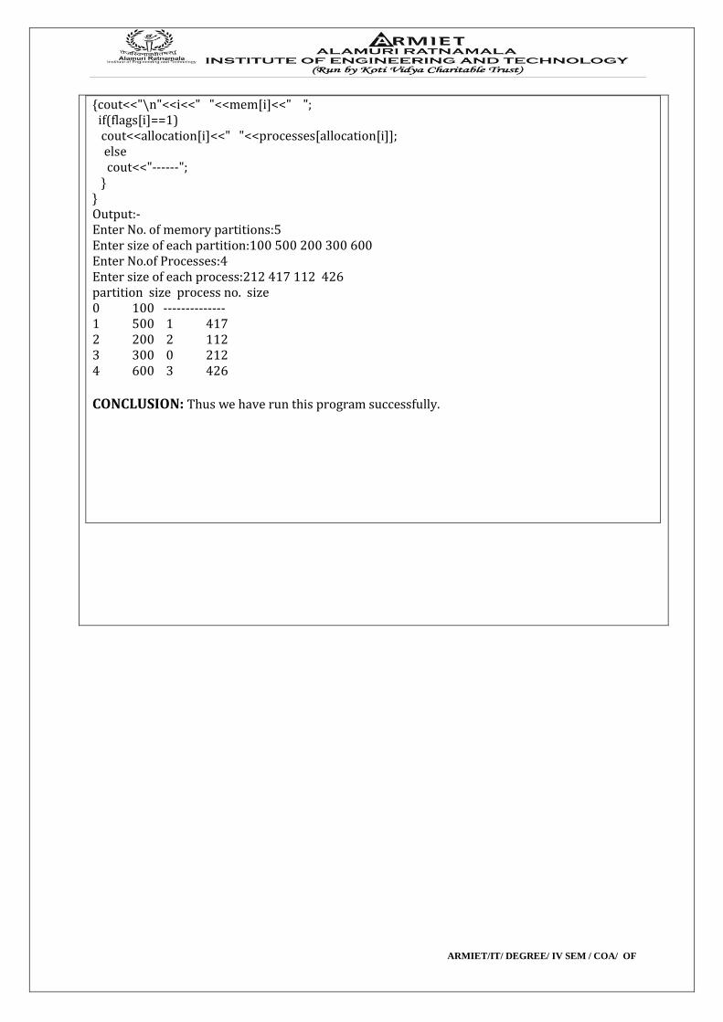
{cout<<"\n"<<i<<" "<<mem[i]<<" "; if(flags[i]==1) cout<<allocation[i]<<" "<<processes[allocation[i]]; else cout<<"------"; } } Output:- Enter No. of memory partitions:5 Enter size of each partition:100 500 200 300 600 Enter No.of Processes:4 Enter size of each process:212 417 112 426 partition size process no. size 0 100 -------------- 1 500 1 417 2 200 2 112 3 300 0 212 4 600 3 426
CONCLUSION: Thus we have run this program successfully.