Embed Size (px)
Citation preview
706.01
ITEM 706 CONCRETE AND CLAY PIPE
706.01 Non-Reinforced Concrete Pipe. Provide non-reinforced concrete pipe conforming to ASTM C 14, with the following modifications:
5.3 Does not apply.
6.2 Provide cementitious materials conforming to 701, except 701.07.
6.3 Provide aggregate conforming to the quality requirements of 703.02.
10.3 Perform external load crushing strength tests with hard rubber blocks on wood strips with plaster of paris bedding fillets.
13 Perform inspection at the project site. Obtain random samples from materials delivered to the project site or at other locations designated by the Laboratory. Provide material manufacturer certification by the Laboratory.
15 Ensure that the markings also include “P” to denote non-reinforced pipe.
Testing Equipment. Ensure that every manufacturer furnishing concrete pipe under these Specifications furnishes all facilities and personnel needed to perform the tests.
706.02 Reinforced Concrete Circular Pipe. Provide reinforced concrete circular pipe conforming to ASTM C 655, with the following modifications:
Provide reinforced concrete pipe that meets the following minimum D-Load :
Size Minimum D-Load 12 in 2000 lb 15 in 2000 lb 18 in 1250 lb 21 in 1250 lb 24 in 1250 lb
27 in or larger 1000 lb
1 Provide circular reinforced concrete pipe with circular or elliptical reinforcement, with and without quadrant and “S” strip reinforcement.
4.1 The City will determine acceptability of the pipe design according to Section 10. The City will accept all designs in ASTM C 76, Tables 2 through 5, inclusive, with the 0.01-inch crack D-loads as follows:
ASTM C 76 Table No.
D-Load 0.01-inch
Crack 2 (Class II) 1000 3 (Class III) 1350 4 (Class IV) 2000 5 (Class V) 3000
The City will accept all designs in Tables 706.02-1 through 706.02-4 with noted 0.01-inch crack and ultimate D-loads. For intermediate D-loads, in Tables 2 through 5 of ASTM C 76 steel areas for a given wall thickness the City will allow interpolation between Tables 2 and 3, 3 and 4, and 4 and 5 for a size and D-load as accepted designs.
706.02
Use the highest of the concrete strengths listed in the tables. In addition, the City will accept steel area designs interpolated as above between Table 706.02-1 and Table 706.02-2, 36-inch through 108-inch using the higher concrete strength, and interpolation of the circumferential steel between Table 706.02-3 and Table 706.02-4 using the wall thickness and stirrup designs in Table 706.02-4. The Laboratory has the option of accepting pipe manufactured according to an accepted pipe design, according to the basis of acceptance described in Section 4.1.1 or 4.1.2.
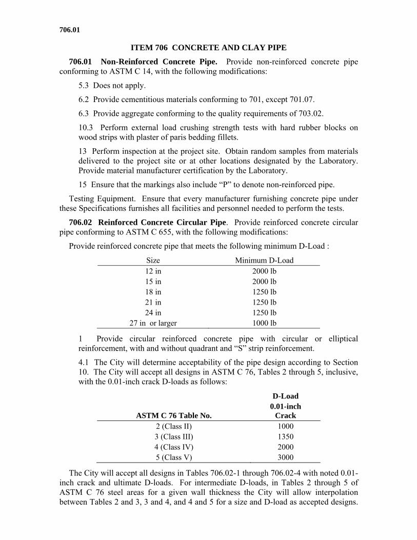
Provide reinforced concrete pipe with S-stirrups according to Figure 1 and the following requirements:
1. Provide steel conforming to 709.08, 709.10, 709.11, or 709.12. Ensure that the wall thickness, amount of circular reinforcement, S-stirrup system, and concrete strength comply with Tables 706.02-2, 706.02-3, and 706.02-4. Ensure that the spacing center-to-center of adjacent inner rings of circumferential reinforcement in a cage does not exceed 4 inches for pipe up to and including pipe having a 4 inches wall thickness or exceed wall thicknesses for larger pipe and in no case exceed 6 inches.
2. Ensure that each line of S-stirrups has a continuous “S” shape extending longitudinally from end to end of the pipe. Ensure that they extend from the inner cage toward the outer surface of the pipe for a distance not less than the minimum amplitude. Ensure that S-stirrups pass around and contact each inside circumferential member of the inner cage. Ensure that each line of S-stirrups lie essentially in a plane passing through the longitudinal axis of the pipe.
3. Where using more than one length of stirrup material per line, make a lap round one circumferential member of the inner cage. Ensure that the ends of “S” shaped stirrups at splices include an outer bend. Do not use more than three lengths of “S” material in a line and ensure a 30-inch minimum length of a section of S-stirrups.
Illustrative Example of S-Stirrup Support System for 0.01-inch Crack D-load 3000, 102-inch diameter Pipe Minimum Area Per Support 0.053 square inch, 11 Lines Spaced @ 5 1/8 inches. For other classes and sizes, see Tables 706.02-2, 3,
and 4.
706.02
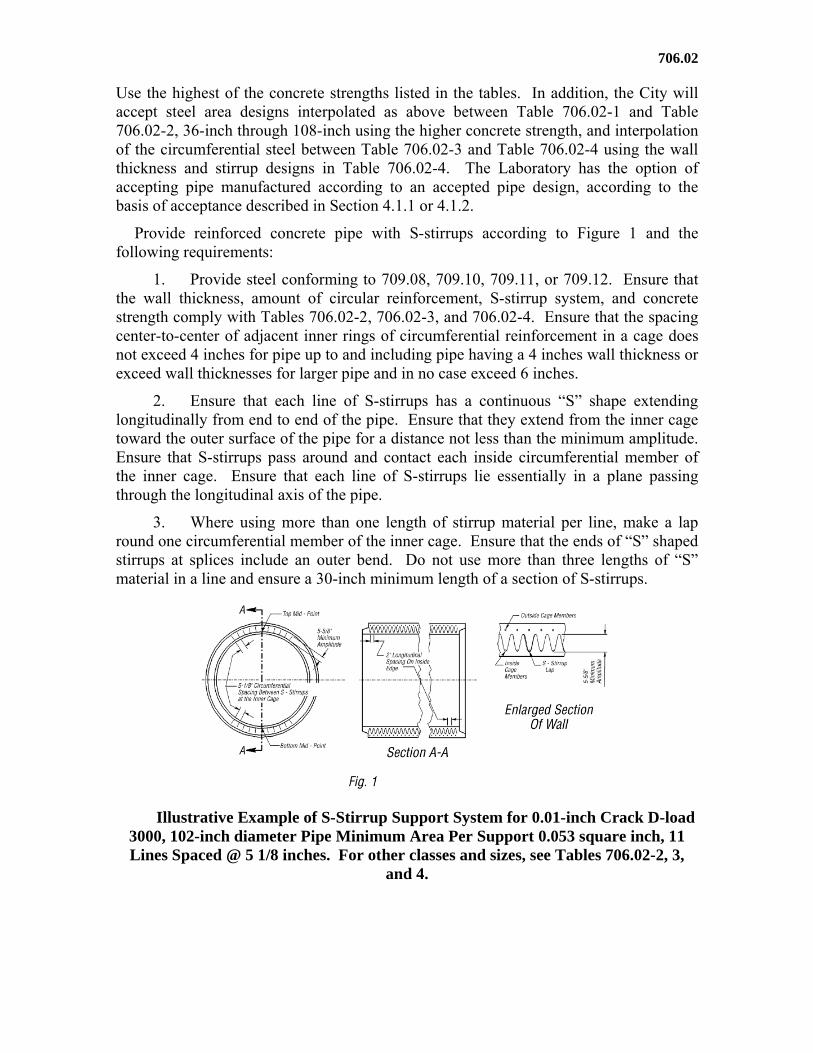
TABLE 706.02-1
0.01-inch Crack D-Load 1000 Ultimate Strength D-Load 1500
Internal Diameter of
Pipe (in)
Wall Thickness
(in)
Circular Reinforcement in Circular Pipe
Inner Cage (in2/ft of pipe)
Outer Cage (in2/ft of pipe)
Reinforcing Steel 709.11 or 709.12 Only Concrete Strength 4000 psi
36 4 0.09 0.07 42 4 1/2 0.11 0.08 48 5 0.13 0.09 54 5 1/2 0.16 0.12 60 6 0.19 0.14 66 6 1/2 0.21 0.16 72 7 0.23 0.17 78 7 1/2 0.25 0.19 84 8 0.29 0.21 90 8 0.33 0.24 96 8 1/2 0.37 0.26
Concrete Strength 5000 psi 102 8 1/2 0.41 0.28 108 9 0.47 0.3
All Permitted Reinforcing Steel Concrete Strength 5000 psi
114 9 1/2 0.56 0.42 120 10 0.61 0.46 126 10 1/2 0.65 0.49 132 11 0.7 0.52 144 12 0.8 0.6
4.1.1 In addition, test the pipe designs covered by Tables 706.02-1, 706.02-2, 706.02-3, and 706.02-4 and ASTM C 76, Tables 2 through 5, and test interpolated designs by the three-edge bearing method. When the test load on the pipe reaches 115 percent of the required 0.01-inch crack D-load without developing a 0.01-inch or larger crack, the City will accept the test specimen for strength. If any test specimen fails to pass this test, but attained the 0.01-inch crack, continue the test until reaching the ultimate D-load.
4.1.2 In addition, the City will accept pipe 54 inches and larger in diameter covered by Tables 706.02-1, 706.02-2, 706.02-3, and 706.02-4, and ASTM C 76, Tables 2 through 5, and interpolated designs according to Section 12 and the following requirements:
1. For pipe from a plant approved by the Laboratory for a specified design, pipe from the same plant will be accepted if the wall and steel area not less than the approved pipe.
2. When two or more plants comply with the above requirements for the class and size under consideration, and the plant under consideration establishes
706.02
compliance with the above requirements for an adjacent size, and the wall and steel area not less than the pipe tested at the two plants.
6.1.2.1 Provide cement according to 701.
6.1.2.2 Provide fly ash according to 701.13
6.1.3 Provide aggregates conforming to the quality requirements of 703.02.
6.1.5 Provide steel according to 709.08, 709.10, 709.11, or 709.12.
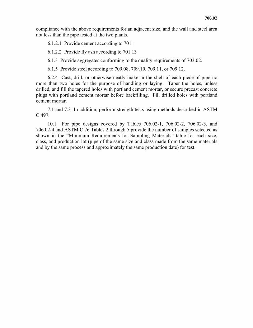
6.2.4 Cast, drill, or otherwise neatly make in the shell of each piece of pipe no more than two holes for the purpose of handling or laying. Taper the holes, unless drilled, and fill the tapered holes with portland cement mortar, or secure precast concrete plugs with portland cement mortar before backfilling. Fill drilled holes with portland cement mortar.
7.1 and 7.3 In addition, perform strength tests using methods described in ASTM C 497.
10.1 For pipe designs covered by Tables 706.02-1, 706.02-2, 706.02-3, and 706.02-4 and ASTM C 76 Tables 2 through 5 provide the number of samples selected as shown in the “Minimum Requirements for Sampling Materials” table for each size, class, and production lot (pipe of the same size and class made from the same materials and by the same process and approximately the same production date) for test.
706.02
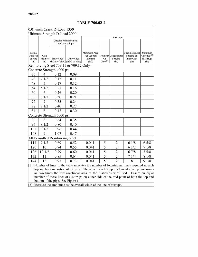
TABLE 706.02-2
0.01-inch Crack D-Load 1350 Ultimate Strength D-Load 2000
Internal Diameter of Pipe
(in)
Wall Thickness
(in)
Circular Reinforcement in Circular Pipe
S-Stirrups
Minimum Area Per Support
Element (in2)
NumberOf
Lines[1]
LongitudinalSpacing
(in)
Circumferential Spacing on Inner Cage
(in)
Minimum Amplitude[2] of Stirrups
(in) Inner Cage
(in2/ft of pipe) Outer Cage
(in2/ft of pipe)
Reinforcing Steel 709.11 or 709.12 Only Concrete Strength 4000 psi
36 4 0.12 0.09 42 4 1/2 0.15 0.11 48 5 0.17 0.12 54 5 1/2 0.21 0.16 60 6 0.26 0.20 66 6 1/2 0.30 0.21 72 7 0.35 0.24 78 7 1/2 0.40 0.27 84 8 0.47 0.30
Concrete Strength 5000 psi 90 8 0.64 0.35 96 8 1/2 0.80 0.40 102 8 1/2 0.96 0.44 108 9 1.07 0.47
All Permitted Reinforcing Steel 114 9 1/2 0.69 0.52 0.041 5 2 6 1/8 6 5/8 120 10 0.74 0.55 0.041 5 2 6 1/2 7 1/8 126 10 1/2 0.79 0.60 0.041 5 2 6 7/8 7 5/8 132 11 0.85 0.64 0.041 5 2 7 1/4 8 1/8 144 12 0.97 0.73 0.041 5 2 8 9 1/8
[1] Number of lines in the table indicates the number of longitudinal lines required in eachtop and bottom portion of the pipe. The area of each support element in a pipe measuresas two times the cross-sectional area of the S-stirrups wire used. Ensure an equal number of these lines of S-stirrups on either side of the mid-point of both the top and bottom of the pipe. See Figure 1.
[2] Measure the amplitude as the overall width of the line of stirrups.
706.02
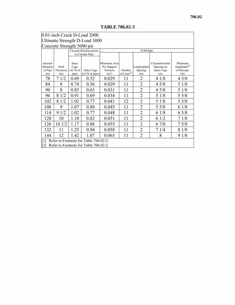
TABLE 706.02-3
0.01-inch Crack D-Load 2000 Ultimate Strength D-Load 3000 Concrete Strength 5000 psi
Internal Diameter of Pipe
(in)
Wall Thickness
(in)
Circular Reinforcement in Circular Pipe
S-Stirrups
Minimum AreaPer Support
Element (in2)
Number of Lines[1]
LongitudinalSpacing
(in)
Circumferential Spacing on Inner Cage
(in)
Minimum Amplitude[2]
of Stirrups (in)
Inner Cage
(in2/ft of pipe)
Outer Cage (in2/ft of pipe)
78 7 1/2 0.69 0.52 0.029 11 2 4 1/8 4 5/8 84 8 0.74 0.56 0.029 11 2 4 5/8 5 1/8 90 8 0.85 0.63 0.031 11 2 4 5/8 5 1/8 96 8 1/2 0.91 0.69 0.034 11 2 5 1/8 5 5/8 102 8 1/2 1.02 0.77 0.041 12 2 5 1/8 5 5/8 108 9 1.07 0.80 0.045 11 2 5 5/8 6 1/8 114 9 1/2 1.02 0.77 0.048 11 2 6 1/8 6 5/8 120 10 1.10 0.82 0.051 11 2 6 1/2 7 1/8 126 10 1/2 1.17 0.88 0.055 11 2 6 7/8 7 5/8 132 11 1.25 0.94 0.058 11 2 7 1/4 8 1/8 144 12 1.42 1.07 0.065 11 2 8 9 1/8
[1] Refer to Footnote for Table 706.02-2. [2] Refer to Footnote for Table 706.02-2.
706.02
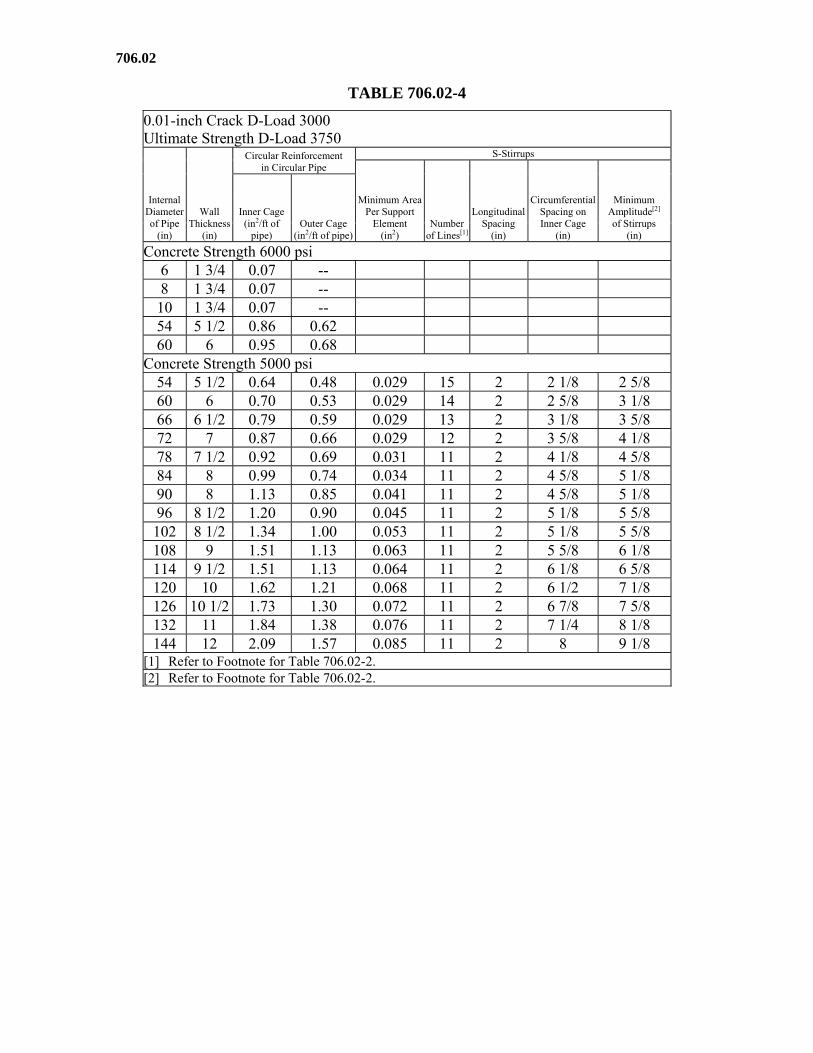
TABLE 706.02-4
0.01-inch Crack D-Load 3000 Ultimate Strength D-Load 3750
Internal Diameter of Pipe
(in)
Wall Thickness
(in)
Circular Reinforcement in Circular Pipe
S-Stirrups
Minimum AreaPer Support
Element (in2)
Number of Lines[1]
LongitudinalSpacing
(in)
Circumferential Spacing on Inner Cage
(in)
Minimum Amplitude[2]
of Stirrups (in)
Inner Cage (in2/ft of
pipe) Outer Cage
(in2/ft of pipe)
Concrete Strength 6000 psi 6 1 3/4 0.07 -- 8 1 3/4 0.07 --
10 1 3/4 0.07 -- 54 5 1/2 0.86 0.62 60 6 0.95 0.68
Concrete Strength 5000 psi 54 5 1/2 0.64 0.48 0.029 15 2 2 1/8 2 5/8 60 6 0.70 0.53 0.029 14 2 2 5/8 3 1/8 66 6 1/2 0.79 0.59 0.029 13 2 3 1/8 3 5/8 72 7 0.87 0.66 0.029 12 2 3 5/8 4 1/8 78 7 1/2 0.92 0.69 0.031 11 2 4 1/8 4 5/8 84 8 0.99 0.74 0.034 11 2 4 5/8 5 1/8 90 8 1.13 0.85 0.041 11 2 4 5/8 5 1/8 96 8 1/2 1.20 0.90 0.045 11 2 5 1/8 5 5/8 102 8 1/2 1.34 1.00 0.053 11 2 5 1/8 5 5/8 108 9 1.51 1.13 0.063 11 2 5 5/8 6 1/8 114 9 1/2 1.51 1.13 0.064 11 2 6 1/8 6 5/8 120 10 1.62 1.21 0.068 11 2 6 1/2 7 1/8 126 10 1/2 1.73 1.30 0.072 11 2 6 7/8 7 5/8 132 11 1.84 1.38 0.076 11 2 7 1/4 8 1/8 144 12 2.09 1.57 0.085 11 2 8 9 1/8
[1] Refer to Footnote for Table 706.02-2. [2] Refer to Footnote for Table 706.02-2.
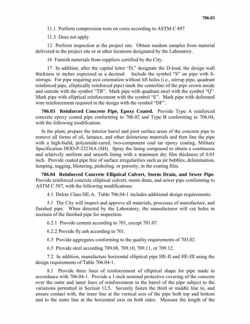
706.03
11.1 Perform compression tests on cores according to ASTM C 497
11.3 Does not apply.
12 Perform inspection at the project site. Obtain random samples from material delivered to the project site or at other locations designated by the Laboratory.
16 Furnish materials from suppliers certified by the City.
17 In addition, after the capital letter “D,” designate the D-load, the design wall thickness in inches expressed as a decimal. Include the symbol “S” on pipe with S-stirrups. For pipe requiring axis orientation without lift holes (i.e., stirrup pipe, quadrant reinforced pipe, elliptically reinforced pipe) mark the centerline of the pipe crown inside and outside with the symbol “TB”. Mark pipe with quadrant steel with the symbol “Q”. Mark pipe with elliptical reinforcement with the symbol “E”. Mark pipe with deformed wire reinforcement required in the design with the symbol “DF”.
706.03 Reinforced Concrete Pipe, Epoxy Coated. Provide Type A reinforced concrete epoxy coated pipe conforming to 706.02 and Type B conforming to 706.04, with the following modification:
In the plant, prepare the interior barrel and joint surface areas of the concrete pipe to remove all forms of oil, laitance, and other deleterious materials and then line the pipe with a high-build, polyamide-cured, two-component coal tar epoxy coating, Military Specification DOD-P-23236A (SH). Spray the lining compound to obtain a continuous and relatively uniform and smooth lining with a minimum dry film thickness of 0.03 inch. Provide coated pipe free of surface irregularities such as air bubbles, delamination, lumping, sagging, blistering, pinholing, or porosity, in the coating film.
706.04 Reinforced Concrete Elliptical Culvert, Storm Drain, and Sewer Pipe. Provide reinforced concrete elliptical culvert, storm drain, and sewer pipe conforming to ASTM C 507, with the following modifications:
4.1 Delete Class HE-A. Table 706.04-1 includes additional design requirements.
5.1 The City will inspect and approve all materials, processes of manufacture, and finished pipe. When directed by the Laboratory, the manufacturer will cut holes in sections of the finished pipe for inspection.
6.2.1 Provide cement according to 701, except 701.07.
6.2.2 Provide fly ash according to 701.
6.3 Provide aggregates conforming to the quality requirements of 703.02.
6.5 Provide steel according 709.08, 709.10, 709.11, or 709.12.
7.2 In addition, manufacture horizontal elliptical pipe HE-II and HE-III using the design requirements of Table 706.04-1.
8.1 Provide three lines of reinforcement of elliptical shape for pipe made in accordance with 706.04-1. Provide a 1-inch nominal protective covering of the concrete over the outer and inner lines of reinforcement in the barrel of the pipe subject to the variations permitted in Section 12.5. Securely fasten the third or middle line to, and ensure contact with, the inner line at the vertical axis of the pipe both top and bottom and to the outer line at the horizontal axis on both sides. Measure the length of the
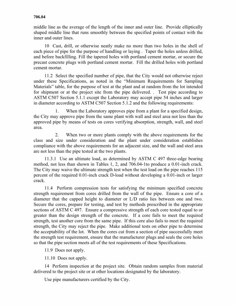
706.04
middle line as the average of the length of the inner and outer line. Provide elliptically shaped middle line that runs smoothly between the specified points of contact with the inner and outer lines.
10 Cast, drill, or otherwise neatly make no more than two holes in the shell of each piece of pipe for the purpose of handling or laying . Taper the holes unless drilled, and before backfilling. Fill the tapered holes with portland cement mortar, or secure the precast concrete plugs with portland cement mortar. Fill the drilled holes with portland cement mortar.
11.2 Select the specified number of pipe, that the City would not otherwise reject under these Specifications, as noted in the “Minimum Requirements for Sampling Materials” table, for the purpose of test at the plant and at random from the lot intended for shipment or at the project site from the pipe delivered. . Test pipe according to ASTM C507 Section 5.1.1 except the Laboratory may accept pipe 54 inches and larger in diameter according to ASTM C507 Section 5.1.2 and the following requirements:
1. When the Laboratory approves pipe from a plant for a specified design, the City may approve pipe from the same plant with wall and steel area not less than the approved pipe by means of tests on cores verifying absorption, strength, wall, and steel area.
2. When two or more plants comply with the above requirements for the class and size under consideration and the plant under consideration establishes compliance with the above requirements for an adjacent size, and the wall and steel area are not less than the pipe tested at the two plants.
11.3.1 Use an ultimate load, as determined by ASTM C 497 three-edge bearing method, not less than shown in Tables 1, 2, and 706.04-1to produce a 0.01-inch crack. The City may waive the ultimate strength test when the test load on the pipe reaches 115 percent of the required 0.01-inch crack D-load without developing a 0.01-inch or larger crack.
11.4 Perform compression tests for satisfying the minimum specified concrete strength requirement from cores drilled from the wall of the pipe. Ensure a core of a diameter that the capped height to diameter or L/D ratio lies between one and two. Secure the cores, prepare for testing, and test by methods prescribed in the appropriate sections of ASTM C 497. Ensure a compressive strength of each core tested equal to or greater than the design strength of the concrete. If a core fails to meet the required strength, test another core from the same pipe. If this core also fails to meet the required strength, the City may reject the pipe. Make additional tests on other pipe to determine the acceptability of the lot. When the cores cut from a section of pipe successfully meet the strength test requirement, ensure that the manufacturer plugs and seals the core holes so that the pipe section meets all of the test requirements of these Specifications.
11.9 Does not apply.
11.10 Does not apply.
14 Perform inspection at the project site. Obtain random samples from material delivered to the project site or at other locations designated by the laboratory.
Use pipe manufacturers certified by the City.
706.05
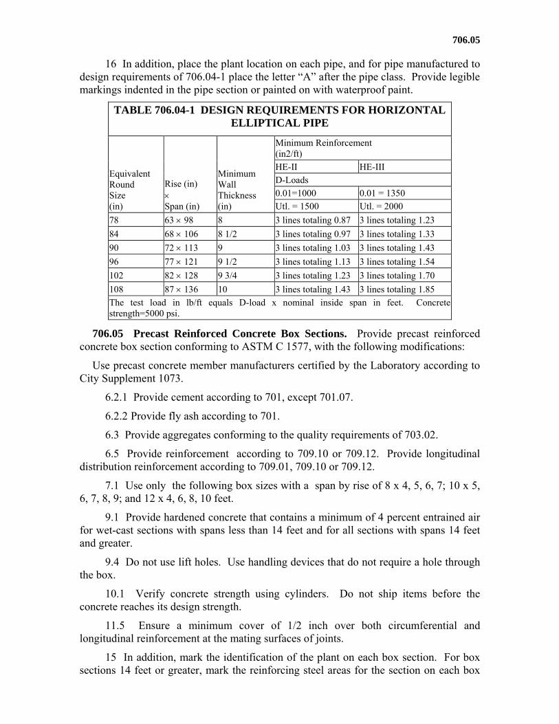
16 In addition, place the plant location on each pipe, and for pipe manufactured to design requirements of 706.04-1 place the letter “A” after the pipe class. Provide legible markings indented in the pipe section or painted on with waterproof paint.
TABLE 706.04-1 DESIGN REQUIREMENTS FOR HORIZONTAL ELLIPTICAL PIPE
Equivalent Round Size (in)
Rise (in) Span (in)
Minimum Wall Thickness (in)
Minimum Reinforcement (in2/ft)
HE-II HE-III
D-Loads
0.01=1000 0.01 = 1350
Utl. = 1500 Utl. = 2000
78 63 98 8 3 lines totaling 0.87 3 lines totaling 1.23
84 68 106 8 1/2 3 lines totaling 0.97 3 lines totaling 1.33
90 72 113 9 3 lines totaling 1.03 3 lines totaling 1.43
96 77 121 9 1/2 3 lines totaling 1.13 3 lines totaling 1.54
102 82 128 9 3/4 3 lines totaling 1.23 3 lines totaling 1.70
108 87 136 10 3 lines totaling 1.43 3 lines totaling 1.85
The test load in lb/ft equals D-load x nominal inside span in feet. Concretestrength=5000 psi.
706.05 Precast Reinforced Concrete Box Sections. Provide precast reinforced concrete box section conforming to ASTM C 1577, with the following modifications:
Use precast concrete member manufacturers certified by the Laboratory according to City Supplement 1073.
6.2.1 Provide cement according to 701, except 701.07.
6.2.2 Provide fly ash according to 701.
6.3 Provide aggregates conforming to the quality requirements of 703.02.
6.5 Provide reinforcement according to 709.10 or 709.12. Provide longitudinal distribution reinforcement according to 709.01, 709.10 or 709.12.
7.1 Use only the following box sizes with a span by rise of 8 x 4, 5, 6, 7; 10 x 5, 6, 7, 8, 9; and 12 x 4, 6, 8, 10 feet.
9.1 Provide hardened concrete that contains a minimum of 4 percent entrained air for wet-cast sections with spans less than 14 feet and for all sections with spans 14 feet and greater.
9.4 Do not use lift holes. Use handling devices that do not require a hole through the box.
10.1 Verify concrete strength using cylinders. Do not ship items before the concrete reaches its design strength.
11.5 Ensure a minimum cover of 1/2 inch over both circumferential and longitudinal reinforcement at the mating surfaces of joints.
15 In addition, mark the identification of the plant on each box section. For box sections 14 feet or greater, mark the reinforcing steel areas for the section on each box
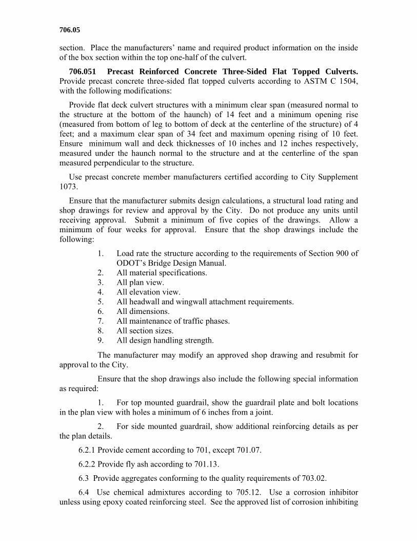
706.05
section. Place the manufacturers’ name and required product information on the inside of the box section within the top one-half of the culvert.
706.051 Precast Reinforced Concrete Three-Sided Flat Topped Culverts. Provide precast concrete three-sided flat topped culverts according to ASTM C 1504, with the following modifications:
Provide flat deck culvert structures with a minimum clear span (measured normal to the structure at the bottom of the haunch) of 14 feet and a minimum opening rise (measured from bottom of leg to bottom of deck at the centerline of the structure) of 4 feet; and a maximum clear span of 34 feet and maximum opening rising of 10 feet. Ensure minimum wall and deck thicknesses of 10 inches and 12 inches respectively, measured under the haunch normal to the structure and at the centerline of the span measured perpendicular to the structure.
Use precast concrete member manufacturers certified according to City Supplement 1073.
Ensure that the manufacturer submits design calculations, a structural load rating and shop drawings for review and approval by the City. Do not produce any units until receiving approval. Submit a minimum of five copies of the drawings. Allow a minimum of four weeks for approval. Ensure that the shop drawings include the following:
1. Load rate the structure according to the requirements of Section 900 of ODOT’s Bridge Design Manual.
2. All material specifications. 3. All plan view. 4. All elevation view. 5. All headwall and wingwall attachment requirements. 6. All dimensions. 7. All maintenance of traffic phases. 8. All section sizes. 9. All design handling strength.
The manufacturer may modify an approved shop drawing and resubmit for approval to the City.
Ensure that the shop drawings also include the following special information as required:
1. For top mounted guardrail, show the guardrail plate and bolt locations in the plan view with holes a minimum of 6 inches from a joint.
2. For side mounted guardrail, show additional reinforcing details as per the plan details.
6.2.1 Provide cement according to 701, except 701.07.
6.2.2 Provide fly ash according to 701.13.
6.3 Provide aggregates conforming to the quality requirements of 703.02.
6.4 Use chemical admixtures according to 705.12. Use a corrosion inhibitor unless using epoxy coated reinforcing steel. See the approved list of corrosion inhibiting
706.05
admixtures on file at the Laboratory. Ensure that the manufacturers recognize that the corrosion inhibitors and admixtures may have an effect on strength, entrained air content, workability, etc. of their concrete mixes. The manufacturers choice of one of these corrosion inhibitors does not alleviate meeting all design requirements of this structure.
6.4.1 Provide air-entraining admixture according to 705.10.
6.5 Provide epoxy coated reinforcement according to 709.00, Grade 60, or 709.14. In lieu of epoxy coated reinforcement, the City will allow the addition of an approved corrosion inhibiting admixture to the concrete at the approved dosage; and provide reinforcement according to 709.01, 709.03 or 709.05; Grade 60 or 709.08, 709.10, 709.11 or 709.12. Provide epoxy or galvanized coated connections when connecting a precast structural unit into a cast-in-place structural component or between segments of adjacent precast structural units either manufactured as separate units or across construction joints when manufactured as one unit. Provide epoxy coated reinforcement according to 709.00 or 709.14, for connections designed to use reinforcing steel. Provide galvanized coatings according to 711.02, for connections designed to use connection plates, hardware or concrete inserts.
7.1 Design according to AASHTO LRFD Bridge Design Specifications, Section 12.14. Include a future wearing surface loading of 60 psf.
7.2 Ensure a minimum of 2 inches of concrete cover dimension over reinforcement in the slab and in the exterior of the leg. Ensure that the interior of the leg reinforcement cover tapers from 1 inch at the bottom of the leg to 2 inches at the bottom of the haunch.
Ensure a minimum cover of 1/2 inch on the ends of longitudinal reinforcement. , Use plastic or epoxy coated steel spacers to position the reinforcement even if using a corrosion inhibiting admixture.
8 Construct the top slab with a keyway joint. The keyway provides a void volume equivalent to that of 12 inches prestressed beam as per ODOT Standard Construction Drawing PSBD-2-07. Design the joint in the leg sections to produce a shear key or inter-locking joint. Ensure flat, non-adjoining outside legs. Sandblast the joint surfaces to the satisfaction of the City, or use a 2000 pounds per square inch water blast no more than 14 days prior to shipping. Design that the culvert so that the sections laid together make a continuous line with a smooth interior free of appreciable irregularities, all compatible with the permissible variations of Section 11.
9 Do not apply waterproofing membrane at any location other than the final location shown on the plans.
9.1 Use aggregate, cement, and water manufactured in conformance with 499.06, 499.07, and 499.09.
Meet the temperature requirements of 511.08 and 511.15.
Use a proportion of portland cement not less than 564 pounds per cubic yard of concrete.
706.05
If used, add the corrosion inhibitor as an aqueous solution. Consider the water in the solution as mixing water for the purpose of determining the water to concrete ratio of concrete.
9.2 Cure the three-sided sections in the forms for the length of time required to obtain the specified minimum design handling strength as defined in the shop drawings. Test a cylinder to check each section’s design handling strength. Repeat this test as often as needed. The City will consider only one cylinder passing as proof that the concrete achieved the desired design handling strength requirement. If the shop drawing shows no design handling strengths, then assume 100 percent of the design strength as the minimum handling strength. Ensure that the curing then continues either in or out of the forms until the concrete meets the specified minimum design strength.
9.2.1 To accelerate the cure, the City will allow steam curing using low pressure steam or radiant heat within a suitable insulated enclosure to contain the live steam or heat. Apply the initial steam or heat from two to four hours after the final placement of concrete to allow the initial set to take place. When using retarders, increase the waiting period to 4 to 6 hours. As an alternative, determine the actual time of initial set according to ASTM C 403. Do not start curing until the initial set time.
Maintain a temperature within the curing enclosure of not less than 50 F during the waiting period. During the initial application of live steam or radiant heat, ensure that the ambient temperature within the curing enclosure increases at an average rate not exceeding 40 F per hour until reaching the curing temperature.
Do not exceed a maximum curing temperature of 150 F. Ensure that the Hold the design temperature until reaching the desired design strength. Do not direct the application of live steam on the concrete forms so as to cause localized high temperatures.
9.2.2 Provide water curing according to 511.15 and 511.17, Method A.
9.2.3 Provide membrane curing according to 511.16, Method B.
9.3 Keep all forms in place until meeting the design handling strength.
9.4 Do not make holes for handling or setting. Do not move members before the design handling strength of the concrete is reached, or shipped before the design strength of the concrete is reached. Ensure that the manufacturers possess the equipment needed to handle and transport the pieces without damaging them.
10 Ensure that the hardened concrete contains a minimum of 4 percent entrained air.
10.2.1 Keep the cylinders and matching culvert section together to guarantee the cylinders match with the corresponding culvert section; or, upon agreement by the City, keep the cylinders at a location that provides the same environment as the culvert sections.
10.2.2 For each section of the culvert, produce and mark at least four cylinders in order to ensure identification with the matching culvert section.
10.2.3 Conform to City Supplement 1073 for acceptance.
10.2.3.1 Ensure that cylinder strengths conform to City Supplement 1073.
706.05
10.3.3.2 Deleted.
10.4 Plug the core holes using the same concrete mixture as that used in the section and cured in according to Section 9.2, or by a non-shrink grout that exceeds the concrete design strength.
11 The design in the plan reflects the external top slab elevation of the structure. For a structure supplied with a thicker deck than the plan design, eliminate the difference between the design top slab elevation and the supplied top slab elevation by a reducing the leg length. The City may approve alternate methods to eliminate the difference between the design top slab elevation and the supplied top slab elevation. The City will not approve a change in the top slab elevation from that shown on the plans.
The plan shows the minimum clear span for the structure. The City will allow the Contractor to provide a clear span greater than that shown. Base the exact footer locations for both the elevation and offset on the manufacturer’s shop drawings. Locate the footers to match the centerline of the leg at the bottom of the haunch to the centerline of the footer.
The City will make no additional payment for changes to the project resulting from the manufacturer’s dimensional changes in the structure.
Provide sections free of fractures spalls and chips with a smooth and regular finish defined as a 1/4-inch variation within 4 feet.
11.1 Construct walls perpendicular to the slab with a diagonal difference of not more than 0.5 percent.
Build sections within 1/2 inch of the design length. The City will consider the length as the average of the length measured at each side and at the middle of the three-sided section.
11.4 Ensure a maximum variation of 3/8-inch in the position of the reinforcement . Ensure a cover of no less than 2 inches over the reinforcement for the external surface of the top slab. The above tolerances or cover requirements do not apply to mating surfaces at the joint.
11.5 Resubmit any change in reinforcement from the shop drawings for approval.
12 Make repairs according to the City’s requirements. The City will not make additional payments for culvert repairs. The City will consider sound, properly finished, and cured repairs as acceptable. .
13 Perform inspection at the project site.
Furnish precast concrete components from suppliers certified according to City Supplement 1073.
14 Form seams and slight surface irregularities that are expected from a wood panel forming system will not be cause for rejection. In addition, hairline cracks less than 0.01 inch are not cause for rejection.
15.1 Locate the product marking on the interior of the three-sided section 1 foot below the leg haunch.

706.05
Add the product marking upon removal of the forms.
The manufacturer may be required to repeat the product markings before the project is final.
706.052 Precast Reinforced Concrete Arch Sections. Provide precast reinforced concrete arch sections according to ASTM C 1504, with the following modifications:
This item shall consist of manufacturing precast reinforced concrete arch sections for culverts.
Use precast concrete member manufacturers certified according to City Supplement 1073.
5 Ensure the manufacturer submits design calculations, a structural load rating and shop drawings for review and approval by the City. Do not produce any units until receiving approval. Submit a minimum of five copies of the drawings. Allow a minimum of 4 weeks for approval. Ensure the shop drawings include the following:
1. Load rate the structure according to the requirements of Section 900 of ODOT’s Bridge Design Manual.
2. All material specifications.
3. All plan view.
4. All elevation view.
5. All headwall and wingwall attachment requirements.
6. All dimensions.
7. All maintenance of traffic phases.
8. All section sizes.
9. All design handling strength.
The Contractor may modify an approved shop drawing and resubmit for approval to the City.
Ensure that the shop drawings also include the following special information as required:
1. For top mounted guardrail, show the guardrail plate and bolt locations in the plan view with holes shown as a minimum of 6 inches from a joint.
2. The corrosion inhibitor used, if any. The dosage rate will be as per the manufacturer’s recommendation.
6.2.1 Provide cement according to 701, except 701.07.
6.2.2 Provide fly ash according to 701.13.
6.3 Provide aggregates conforming to the quality requirements of 703.02.
6.4 Use chemical admixtures according to 705.12. Use a corrosion inhibitor unless using epoxy coated reinforcing steel. See an approved list of corrosion inhibiting admixtures on file at the Laboratory. Ensure that the manufacturers recognize the effect on strength, entrained air content, workability, etc. of the concrete mixes resulting from
706.05
use of corrosion inhibitors and admixtures. may have an. The manufacturers choice of one of these corrosion inhibitors does not alleviate meeting all design requirements of this structure.
6.4.1 Provide air-entraining admixture according to 705.10.
6.5 Provide epoxy coated reinforcement according to 709.00, Grade 60, or 709.14. In lieu of epoxy coated reinforcement, the Contractor may add an approved corrosion inhibiting admixture to the concrete at the approved dosage; and provide reinforcement according to 709.01, 709.03 or 709.05; Grade 60 or 709.08, 709.10, 709.11 or 709.12. Provide epoxy or galvanized coated connections when connecting a precast structural unit into a cast-in-place structural component or between segments of adjacent precast structural units either manufactured as separate units or across construction joints when manufactured as one unit. Provide epoxy coated reinforcement according to 709.00 or 709.14, for reinforcing steel designed connections. Provide galvanized coatings according to 711.02, for connection designs using connection plates, hardware or concrete inserts.
7.1 Design according to AASHTO LRFD Bridge Design Specifications, Section 12.14. Include a future wearing surface loading of 60 psf.
7.2 Ensure a 2-inch minimum concrete cover dimension over the outside circumferential reinforcement. Ensure a 1-1/2-inch minimum of concrete cover dimension over the inside circumferential reinforcement. Ensure a clear distance of no less than 1 inch or more than 2 inches from the end circumferential wires to the ends of the sections. Assemble reinforcement using single or multiple layers of welded wire fabric (three-layer maximum), or using a single layer of deformed billet-steel bars. Use welded wire fabric composed of circumferential and longitudinal wires containing sufficient longitudinal wires extending through the section to maintain the shape and position of reinforcement. The City will allow longitudinal distribution reinforcement of welded wire fabric or deformed billet-steel bars. Ensure that the ends of the longitudinal distribution reinforcement extend no more than 3 inches from the ends of the sections.
Bend the outside and inside circumferential reinforcing steel for the corners of the culvert to an angle approximately equal to the configuration of the culverts outside corner.
7.3 Do not make tension splices in the circumferential reinforcement. For splices other than tension splices, the overlap a minimum of 12 inches for welded wire fabric or deformed billet steel bars. Space the circumferential wires in a wire fabric sheet center-to-center no less than 2 inches or more than 4 inches. For the wire fabric, space the longitudinal wire no more than 8 inches center-to-center. Space the longitudinal distribution steel for either line of reinforcing in the top slab no more than 16 inches center-to-center.
8.1 Construct the sections with butt ends. Make the ends of the sections so that the sections laid together form a continuous line of sections with a smooth interior free of appreciable irregularities, all compatible with the permissible variations in these Specifications. Provide a chamfer on the outside surface at the sections joint to form a void for a 7/8 1 3/8-inch flexible plastic gasket 706.14.
706.05
9 Do not apply waterproofing membrane on the arch section at any location other than the final location shown on the plans.
9.1 Use aggregate, cement, and water manufactured according to 499.06, 499.07, and 499.09.
Meet the temperature requirements of 511.08 and 511.15.
Ensure a proportion of portland cement no less than 564 pounds per cubic yard of concrete.
If used, add the corrosion inhibitor as an aqueous solution. Consider the water in the solution as mixing water for the purpose of determining the water-cement ratio of concrete.
9.2 Cure the arch sections in the forms for the length of time required to obtain the specified minimum design handling strength as defined in the shop drawings. Test a cylinder to check each section’s design handling strength. Repeat this test as often as needed. The City will consider only one cylinder passing as meeting the design handling strength. If the shop drawing shows no design handling strengths, then assume the minimum handling strength as 100 percent of the design strength. Ensure that the curing then continues either in or out of the forms until the concrete meets the specified minimum design strength.
9.2.1 The City will accept steam curing by low pressure steam or radiant heat within a suitable insulated enclosure to contain the live steam or heat as an accelerated cure method. Make the initial application of the steam or heat from 2 to 4 hours after the final placement of concrete to allow the initial set to take place. If using retarders, increase the waiting period to 4 to 6 hours. As an alternative, determine the actual time of initial set according to ASTM C 403. Do not start curing until the actual time to initial set elapses.
During the waiting period, ensure a temperature within the curing enclosure of no less than 50 F.
During the initial application of live steam or radiant heat, ensure that the ambient temperature within the curing enclosure increases at an average rate not exceeding 40 F per hour until reaching the curing temperature.
Do not exceed a maximum curing temperature of 150 F. Hold the design temperature until the concrete has reaches the desired design strength. Do not direct the application of live steam on the concrete forms so as to cause localized high temperatures.
9.2.2 Provide water curing according to 511.15 and 511.17, Method A.
9.2.3 Deleted.
9.3 Keep all forms in place until meeting the design handling strength.
Do not make holes for handling or setting. Do not move members before the design handling strength of the concrete is reached, or shipped before the design strength of the concrete is reached. Ensure that the manufacturers possess equipment necessary to handle and transport the pieces without damaging them.
706.05
10 Ensure that the hardened concrete contains a minimum of 4 percent entrained air.
10.2.1 Keep the cylinders and matching culvert section together to guarantee the cylinders stay matched with the corresponding culvert section; or, upon agreement by the City, keep the cylinders at a location that provides the same environment as the culvert sections.
10.2.2 For each section of the culvert, produce and mark at least four cylinders so that they are identifiable with the matching culvert section.
10.2.3 Conform to City Supplement 1073 for acceptance.
10.2.3.1 Ensure that cylinder strengths conform to City Supplement 1073.
10.3.3.2 Deleted
10.4 Plug the core holes with the same concrete mix used in the section and cured according to Section 9.2, or by a non-shrink grout that exceeds the concrete design strength.
11.0 Do not exceed the under-run in length of a section by more than 1/2 inch.
The City will make no additional payment for changes to the project resulting from the manufacturer’s dimensional changes in the structure.
Provide sections free of fractures spalls and chips with smooth and regular surfaces, defined as a 1/4 inch variation within 4 feet.
11.1 Do not vary the internal dimensions by more than the lesser of 1 percent from the design dimensions or 1 1/2 inches. Do not vary the haunch dimensions by more than 3/4 inch from the design dimension.
11.4 Ensure a maximum variation in the position of the reinforcement of 3/8 inch. Provide no less than 2 inches of cover over the reinforcement for the external surface of the top slab. The above tolerances or cover requirements do not apply to mating surfaces at the joint.
11.5 Resubmit any change in reinforcement from the shop drawings for approval.
12.0 Make repairs according to the City’s requirements. The City will not make additional payments for culvert repairs. The City will accept sound, properly finished, and cured repairs.
13.0 Perform inspection at the project site.
Furnish precast concrete components from suppliers certified according to City Supplement 1073.
14.0 Form seams and slight surface irregularities that are expected from a wood panel forming system will not be cause for rejection. In addition, hairline cracks less than 0.01 inch will not be cause for rejection.
15.1 Locate the product marking on the interior of the arch section 1 foot below the leg haunch.
Add the product marking upon removal of the forms.
706.05
The City may require repetitive product markings before Final Acceptance of the Project.
706.053 Precast Reinforced Concrete Round Sections. Provide precast reinforced concrete elliptical and circular arch sections according to ASTM C 1504, with the following modifications:
This item consists of manufacturing precast reinforced concrete elliptical and circular arch sections for culverts.
Use precast concrete member manufacturers of certified according to City Supplement 1073.
5. Ensure the manufacturer submits design calculations, a structural load rating and shop drawings for review and approval by the City. Do not produce any units until receiving approval. Submit a minimum of five copies of the drawings. Allow a minimum of 4 weeks for approval. Ensure the shop drawings include the following:
1. Load rate the structure according to the requirements of section 900 of ODOT’s Bridge Design Manual.
2. All material specifications.
3. Plan view.
4. Elevation views.
5. Headwall and wingwall attachment requirements.
6. Dimensions.
7. All maintenance of traffic phases.
8. Section sizes.
9. Design handling strength.
The City will allow the Contractor to modify an approved shop drawing and resubmit for approval to the City.
Ensure that the shop drawings also include the following special information as required:
1. For top mounted guardrail, show the guardrail plate and bolt locations in the plan view with holes a minimum of 6 inches (150 mm) from a joint.
2. The corrosion inhibitor used, if any, and dosage rate. The Laboratory will approve the dosage rate.
6.2.1 In addition, provide cement according to 701, except 701.07.
6.2.2 Only use fly ash conforming to 701.13.
6.3 Provide aggregates conforming to the quality requirements of 703.02.
6.4 Use chemical admixtures conforming to 705.12. Use a corrosion inhibitor unless using epoxy coated reinforcing steel. See the approved list of corrosion inhibiting admixtures on file at the Laboratory. Ensure that the manufacturers recognize the effect of corrosion inhibitors and admixtures on strength, entrained air content, workability,

706.05
etc. of their concrete mixes. The manufacturer’s choice of one of these corrosion inhibitors does not alleviate meeting all design requirements of this structure.
6.4.1 Provide air-entraining admixture conforming to 705.10.
6.5 Provide epoxy coated reinforcement according to 709.00, Grade 60 (Grade 420), or 709.14. In lieu of epoxy coated reinforcement, the Contractor may add an approved corrosion inhibiting admixture to the concrete at the approved dosage. Provide reinforcement according to 709.01, 709.03 or 709.05; Grade 60 (Grade 420) or 709.08, 709.10, 709.11 or 709.12. Provide epoxy or galvanized coated connections when connecting a precast structural unit into a cast-in-place structural component or between segments of adjacent precast structural units either manufactured as separate units or across construction joints when manufactured as one unit. Provide epoxy coated reinforcement according to 709.00 or 709.14, when designing these connections using reinforcing steel. Provide galvanized coatings according to 711.02, when designing these connections using connection plates, hardware or concrete inserts.
7.1 Modify the first sentence as follows: Design according to AASHTO LRFD Bridge Design Specifications, Section 12.14. Include a future wearing surface loading of 60 psf.
7.2 Ensure a minimum of 2 inches (50 mm) of concrete cover dimension over the outside circumferential reinforcement. Ensure a minimum of 1 1/2 inches (38 mm) of concrete cover dimension over the inside circumferential reinforcement. Ensure a clear distance of the end circumferential wires no less than 1 inch (25 mm) or more than 2 inches (50 mm) from the ends of the sections. Assemble reinforcement utilizing single or multiple layers of welded wire fabric (three-layer maximum), or utilizing a single layer of deformed billet-steel bars. Use welded wire fabric composed of circumferential and longitudinal wires containing sufficient longitudinal wires extending through the section to maintain the shape and position of reinforcement. The City will accept longitudinal distribution reinforcement of welded wire fabric or deformed billet-steel bars. Ensure that the ends of the longitudinal distribution reinforcement extend no more than 3 inches (75 mm) from the ends of the sections.
Form the outside and inside circumferential reinforcing steel for the arch approximately equal to the configuration of the arch shape.
7.3 In addition, do not make tension splices in the circumferential reinforcement. For splices other than tension splices, the overlap a minimum of 12 inches (300 mm) for welded wire fabric or deformed billet steel bars. Space circumferential wires in a wire fabric sheet no less than 2 inches (50 mm) or more than 4 inches (100 mm) center-to-center . For the wire fabric, space the longitudinal wire no more than 8 inches (200 mm) center-to-center . Space the longitudinal distribution steel for either line of reinforcing in the top slab no more than 16 inches (410 mm) center-to-center .
8.1 Construct the sections with butt ends. Ensure that the ends of the sections, when laid together, make a continuous line of sections with a smooth interior free of appreciable irregularities, all compatible with the permissible variations in these Specifications and section 11 of ASTM C 1504. Provide a 3/4 × 3/4 inch (19 × 19 mm) minimum chamfer on the inside and outside surface at the sections joint.
Ensure a structurally continuous arch design throughout the arch unit providing for flexural, compressive and shear force transfers in its final constructed
706.05
location. For arches that gain structural continuity by a cast in place closure at the project site, provide concrete with the same compressive strength as the precast arch. In addition, ensure that the cast in place closure provides continuity in the transverse direction (90 degrees to the span) along the lay length of the arches.
9.1 Use aggregate, cement, and water manufactured according to 499.06, 499.07, and 499.09.
Meet the temperature requirements of 511.08 and 511.15.
Ensure a proportion of Portland cement no less than 564 pounds per cubic yard (335 kg/m3) of concrete.
If used, add the corrosion inhibitor as an aqueous solution. Consider the water in the solution as mixing water for the purpose of determining the water-cement ratio of concrete.
9.2 Cure the arch sections in the forms for the length of time required to obtain the specified minimum design handling strength as defined in the shop drawings. Test a cylinder to check each section’s design handling strength. Repeat this test as often as needed. The City will consider only one cylinder passing as proof of meeting the design handling strength. If the shop drawing shows no design handling strengths, then assume a minimum handling strength of 100 percent of the design strength. Ensure that the curing then continues either in or out of the forms until the concrete meets the specified minimum design strength.
9.2.1 The City will accept steam curing by low pressure steam or radiant heat within a suitable insulated enclosure to contain the live steam or heat as an accelerated cure method. Make the initial application of the steam or heat from 2 to 4 hours after the final placement of concrete to allow the initial set to take place. If using retarders, increase the waiting period to 4 to 6 hours. As an alternative, determine the actual time of initial set according to ASTM C 403. Do not start curing until the actual time to initial set elapses.
During the waiting period, ensure a temperature within the curing enclosure no less than 50 °F (10 °C).
During the initial application of live steam or radiant heat, ensure that the ambient temperature within the curing enclosure increases at an average rate not exceeding 40 °F (22 °C) per hour until reaching the curing temperature.
Ensure that the maximum curing temperature does not exceed 150 °F (65 °C). Hold the design temperature until the concrete reaches the desired design strength. Do not direct the application of live steam on the concrete forms so as to cause localized high temperatures.
9.2.2 Provide water curing according to 511.15 and 511.17, Method A.
9.2.3 Delete.
9.3 Keep all forms place until meeting the design handling strength.
Do not make holes for handling or setting. Do not move members before the design handling strength of the concrete is reached, or shipped before the design strength of the concrete is reached. Ensure that the manufacturers possess equipment necessary to

706.05
handle and transport the pieces without damaging them.10 Ensure that the hardened concrete contains a minimum of 4 percent entrained air.
10.1 Do not drill cores from the section.
10.2.1 Keep the cylinders and matching arch section together to guarantee that the cylinders match the corresponding culvert section; or, upon agreement by the City, keep the cylinders at a location that provides the same environment as the arch sections.
10.2.2 For each section of the arch structure, produce at least four cylinders with markings that identify the cylinders with the matching arch section.
10.2.3 Conform to City Supplement 1073 for acceptance.
10.2.3.1 Ensure that cylinder strengths conform to City Supplement 1073.
11.0 Do not under-run the length of a section by more than 1/2 inch (13 mm).
The City will make no additional payment for changes to the project resulting from the Contractor’s dimensional changes in the structure.
Provide sections free of fractures spalls and chips with smooth surfaces and regular finish defined as a 1/4 inch variation within 4 feet (6 mm variation within 1.2 m).
11.1 Do not vary the internal dimensions by any more than the lesser of 1 percent from the design dimensions or 1 1/2 inches (38 mm). Do not vary the haunch dimensions by more than 3/4 inch (19 mm) from the design dimension.
11.4 Ensure a maximum variation in the position of the reinforcement of 3/8 inch (9 mm). Provide no less than 2 inches (50 mm) of cover over the reinforcement for the external surface of the top. The above tolerances or cover requirements do not apply to mating surfaces at the joint.
11.5 Resubmit any change in reinforcement from the shop drawings for approval.
11.6 Provide a smooth steel form finish for all interior and exterior arch surfaces.
12.0 Make repairs according to the City’s requirements. The City will not make additional payments for arch repairs. The City will accept sound, properly finished, and cured repairs.
13.0 The City may inspect the plant according to City Supplement 1073 and will perform final inspection and acceptance at the project site.
Furnish precast concrete components from suppliers certified according to City Supplement 1073.
14.0 Form seams and slight surface irregularities that are expected from a steel panel forming system will not be cause for rejection. In addition, hairline cracks less than 0.01 inch (0.25 mm) will not be cause for rejection.
15.1 Locate the product marking on the interior of the arch section 4 feet (1.2 m) above the base of the arch. Measure the 4 feet (1.2 m) from the base of the arch along the circumference of the interior surface.
Add the product marking upon removal of the forms.
706.06
The manufacturer may be required to repeat the product markings before the project is final.
706.06 Perforated Concrete Pipe. Provide perforated concrete pipe according to ASTM C 444, and 706.01 or 706.02.
Use materials from manufacturers certified by the City.
706.07 Concrete Drain Tile. Provide extra-quality concrete drain tile according to ASTM C 412, with the following modifications:
Use materials from manufacturers certified by the City.
4.0 This specification covers extra-quality concrete drain tile only.
5.1(3) Does not apply.
6.2.1 Provide cement according to 701, except 701.07.
6.2.2 Provide fly ash according to 701.13
6.3 Provide aggregate conforming to the quality requirements of 703.02.
8.1 Perform inspection at the project site. Obtain random samples from material delivered to the project site or at other locations designated by the Laboratory. Use materials from manufacturers certified by the City.
Testing. Ensure that the manufacturer furnishes all facilities and personnel to carry out the tests.
706.08 Vitrified Clay Pipe. Provide vitrified clay pipe according to ASTM C 700, with the following modifications:
Furnish materials according to the City’s Consignment List.
14.0 Perform all tests except hydrostatic according to ASTM C 301.
15.0 Perform inspection at the project site. Obtain random samples from material delivered to the project site or at other locations designated by the Laboratory.
706.09 Clay Drain Tile. Provide extra-quality clay drain tile according to ASTM C 4, with the following modifications:
6.1 Perform inspection at the project site. Obtain random samples from material delivered to the project site or at other locations designated by the Laboratory.
11, 12, and 13 Ensure that the manufacturer furnishes all facilities and personnel to carry out the tests.
Furnish materials according to the City’s Consignment List.
706.10 Bituminous Pipe Joint Filler. Provide cold applied, mineral filled, joint sealing compound for joints of bell and spigot, or tongue and groove sewer; or drain pipe conforming to the following:
A. Composition. Provide a steam-refined petroleum asphalt or a refined coal tar, dissolved in a suitable solvent, and containing an appropriate stiffener.
B. General Requirement. Provide a bituminous plastic cement that has a smooth, uniform mixture, not thickened or livered, and that shows a separation easily overcome
706.11
by stirring. Provide material of such consistency and properties that allows application with a trowel, a putty knife, or with a caulking gun without pulling or drawing. Provide a material that when applied to metal, concrete, or vitrified clay surfaces, exhibits good adhesive and cohesive properties and has only slight shrinkage after curing. Provide material undamaged by exposure to below freezing temperatures.
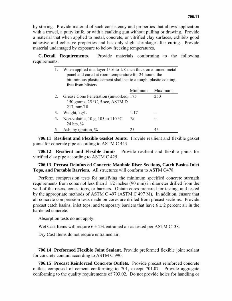
C. Detail Requirements. Provide materials conforming to the following requirements:
1. When applied in a layer 1/16 to 1/8-inch thick on a tinned metal panel and cured at room temperature for 24 hours, the bituminous plastic cement shall set to a tough, plastic coating, free from blisters.
Minimum Maximum 2. Grease Cone Penetration (unworked,
150 grams, 25 C, 5 sec, ASTM D 217, mm/10
175 250
3. Weight, kg/L 1.17 -- 4. Non-volatile, 10 g, 105 to 110 C,
24 hrs, % 75 --
5. Ash, by ignition, % 25 45
706.11 Resilient and Flexible Gasket Joints. Provide resilient and flexible gasket joints for concrete pipe according to ASTM C 443.
706.12 Resilient and Flexible Joints. Provide resilient and flexible joints for vitrified clay pipe according to ASTM C 425.
706.13 Precast Reinforced Concrete Manhole Riser Sections, Catch Basins Inlet Tops, and Portable Barriers. All structures will conform to ASTM C478.
Perform compression tests for satisfying the minimum specified concrete strength requirements from cores not less than 3 1/2 inches (90 mm) in diameter drilled from the wall of the risers, cones, tops, or barriers. Obtain cores prepared for testing, and tested by the appropriate methods of ASTM C 497 (ASTM C 497 M). In addition, ensure that all concrete compression tests made on cores are drilled from precast sections. Provide precast catch basins, inlet tops, and temporary barriers that have 6 2 percent air in the hardened concrete.
Absorption tests do not apply.
Wet Cast Items will require 6 2% entrained air as tested per ASTM C138.
Dry Cast Items do not require entrained air.
706.14 Preformed Flexible Joint Sealant. Provide preformed flexible joint sealant for concrete conduit according to ASTM C 990.
706.15 Precast Reinforced Concrete Outlets. Provide precast reinforced concrete outlets composed of cement conforming to 701, except 701.07. Provide aggregate conforming to the quality requirements of 703.02. Do not provide holes for handling or

Outlets.
laying. Provide concrete outlets with the outlet hole the same size as the outlet pipe. Perform inspection at the project site.
Use manufacturers certified according to City Supplement 1073.