Embed Size (px)
Citation preview

Evolution Canopy System Installation Guide
1
Tools Required:
Power Drill/Driver, HSS Drill Bits – 3mm/7mm/8mm, Masonry Drill Bits – 6mm/8mm, Silicone Gun, Spirit Level, Mallet & Hammer, Step Ladders
Items Supplied:
Star Drive Bit, Posi Drive Bit, Silicone Sealant, Fixings, GutterGrid
Canopy Components
Glazing Bar End Bar Wall Plate
Eaves Beam/Gutter Sheet End Trim Canopy Post (Leg)
Prior to Installation, please ensure the following conditions have been met:
The host wall and base should be made of a sound construction, suitable for fixing this system into position.
Base for canopy posts should be of a solid concrete construction
Fixings provided must be checked for suitability to your application before proceeding with installation.
We recommend the canopy is installed by two people due to the size and weight of certain components.

Evolution Canopy System Installation Guide
2
Step 1.0 Eaves Beam/Gutter preparation Apply a bead of silicone sealant to the edge of the eaves/beam gutter.
Step 1.1 Eaves Beam/Gutter preparation Fix the end cap to the end of the eaves/ beam gutter using the self tapping screws and cover cap provided. Wipe off excess silicone from outside edge. NB do not fit screw“X” as this is fitted later.
Step 1.2 Eaves Beam/Gutter preparation Once the end caps are fitted, apply another bead of silicone to the inside edge
Step 1.3 Eaves Beam/Gutter preparation Determine and mark the position of the post legs on the underside of the eaves/ beam gutter. Select the drainage post/s and drill a central 40mm hole. NB. Alternatively a series of small holes can be drilled in a circular pattern to achieve the same result.
Step 1.4 Eaves Beam/Gutter preparation
To ensure leaves and debris do not block the water outlet, install a small section of gutter grid as per diagram. This can be fixed into position using a small bead of silicone if required.
Step 1.5 Eaves Beam/Gutter preparation
Once the pilot hole has been drilled
permanently fix post/s into position
using two self tapping screws per side.
Ensure legs are square to eaves beam
before screws are fitted.
Step 2.0 Wall Plate Preparation
Determine the pitch required using the
table provided on page 5, then measure
and mark the host wall at the correct
height.
NB all measurements shown are the
height to underside of the wall plate
NB the dimensions are for standard 2.25m posts. For 3m posts add 750mm to the dimensions.
Step 2.1 Wall Plate Preparation
Using a 7mm HSS drill bit pre-drill the
wall plate 100mm from the edge.
Equally space the remaining fixing points
along the wall plate and drill. We
recommend minimum one fixing per
glazing bar along the wall plate.
Evolution Canopy System Installation Guide
3
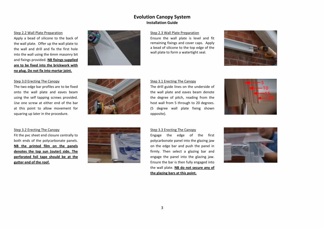
Step 2.2 Wall Plate Preparation
Apply a bead of silicone to the back of
the wall plate. Offer up the wall plate to
the wall and drill and fix the first hole
into the wall using the 6mm masonry bit
and fixings provided. NB fixings supplied
are to be fixed into the brickwork with
no plug. Do not fix into mortar joint.
Step 2.3 Wall Plate Preparation
Ensure the wall plate is level and fit remaining fixings and cover caps. Apply a bead of silicone to the top edge of the wall plate to form a watertight seal.
Step 3.0 Erecting The Canopy
The two edge bar profiles are to be fixed
onto the wall plate and eaves beam
using the self tapping screws provided.
Use one screw at either end of the bar
at this point to allow movement for
squaring up later in the procedure.
Step 3.1 Erecting The Canopy
The drill guide lines on the underside of
the wall plate and eaves beam denote
the degree of pitch, reading from the
host wall from 5 through to 20 degrees.
(5 degree wall plate fixing shown
opposite).
Step 3.2 Erecting The Canopy
Fit the pvc sheet end closure centrally to
both ends of the polycarbonate panels.
NB the printed film on the panels
denotes the top sun (outer) side. The
perforated foil tape should be at the
gutter end of the roof.
Step 3.3 Erecting The Canopy
Engage the edge of the first
polycarbonate panel into the glazing jaw
on the edge bar and push the panel in
firmly. Then select a glazing bar and
engage the panel into the glazing jaw.
Ensure the bar is then fully engaged into
the wall plate. NB do not secure any of
the glazing bars at this point.

Evolution Canopy System Installation Guide
4
Step 3.4 Erecting The Canopy
Repeat the bar fitting procedure with all
the remaining panels and glazing bars
until one panel remains. Now remove
the edge bar to allow access of the last
panel and then refit. Structure now
needs to be squared up. PVC end
closures should be flush to wall plate.
Now secure all glazing bars using two
screws at both ends of each bar.
Step 4.0 Fixing Posts
Once the structure is square, level the
posts in both directions using a spirit
level. Drill the concrete pad using an
8mm masonry bit and fix post brackets
to the concrete base using the stud
anchors supplied.
Step 4.1 Fixing Posts
Hammer in fixings and tighten with a
13mm spanner. Check fixings are secure
for your base.
Step 4.2 Fixing Posts
Level the gutter by adjusting the post
over the foot bracket. Once the desired
position is achieved, secure using two
screws & caps either side of the post.
Step 5.0 Fitting Sheet Edge Trim
Apply a bead of silicone to the leading
edge of the pvc sheet end closure at the
gutter end of the canopy to ensure it is
sealed onto the glazing material.
Step 5.1 Fitting Sheet Edge Trim
Position the sheet edge trim profile on top of the glazing bar ends leaving a 10mm gap for water drainage at the end of the sheet.

Evolution Canopy System Installation Guide
5
Step 5.2 Fitting Sheet Edge Trim
Using the screws and caps supplied. Use the sight line on the glazing bars to determine drill position. Use one screw per end bar and two per glazing bar.
Step 5.3 Fitting Sheet Edge Trim
Apply a bead of silicone in front of the edge trim over the glazing bar. Fix screw “X” into position (see step 1.1) and fit wall plate end caps.
This now completes the installation of the canopy.
Wall plate preparation table
Pitch (degs) Projection 1500mm 2000mm 2500mm 3000mm 3500mm 4000mm
5 2417mm 2460mm 2504mm 2547mm 2591mm 2634mm
10 2543mm 2630mm 2717mm 2804mm 2890mm 2977mm
15 2665mm 2795mm 2924mm 3054mm 3183mm 3312mm
20 2784mm 2955mm 3126mm 3297mm 3468mm 3639mm
Based upon standard 2.25m post lengths and including 20mm for foot brackets. Add 750mm for the 3m post upgrade where applicable.
Disclaimer
The manufacturer accepts no responsibility for any injury or consequential losses caused by the use of unsuitable fixings or by installation of the product in any way that differs from that
described herein. Evolution canopies are designed to withstand a loading of 600 N/m2 which is suitable for most domestic applications in the United Kingdom. If you are installing the
canopy in an exposed location please call your supplier to ask about increased loading specifications.
Please refer to www.molan-uk.com for a downloadable colour version of the fitting instructions.


![GV Standard Pitchglaze - Glazing Vision · 08/11/2018 HL 08/11/2018 [3] Flashing kit: - If specified then supplied by GV - Otherwise supplied by others - All lead to be code 4 (apx](https://img.pdfslide.net/doc/110x75/5edb474bad6a402d66656970/gv-standard-pitchglaze-glazing-vision-08112018-hl-08112018-3-flashing-kit.jpg)