Embed Size (px)
Citation preview
International Transaction Journal of Engineering, Management, & Applied Sciences & Technologies
http://TuEngr.com
Group Technology Paves the Road for Automation Ravindra Thamma a*, E. Daniel Kirby a, Amit Ohri a, Paul Rinalidi a and Mark Rajai b
a Robotics and Mechatronics Engineering Technology Program, Department of Manufacturing and Construction Management, Central Connecticut State University USA b Department of Manufacturing System Engineering & Management, California Construction State University Northridge, USA A R T I C L E I N F O
A B S T RA C T
Article history: Received 24 October 2013 Received in revised form 12 December 2013 Accepted 17 December 2013 Available online 19 December 2013 Keywords: GT; Flexible Manufacturing Cell; Flexible Manufacturing System.
Group technology (GT) has traditionally been a manufacturing philosophy in which parts are identified and grouped together to take advantage of their similarities in manufacturing and design. Similar parts are arranged into part families. In manufacturing, since each family possesses similar manufacturing characteristics, the processing of each member of a family is similar. This study illustrates the important role that GT plays in design of an automated manufacturing system. This is accomplished by creating an ideal application of GT to automation with manufacturing machine cells and part families based upon the design and manufacturing process. In this GT scheme, each machine cell takes care of an individual part family and is independent of rest of the system. Manufacturing cells that process such part families have fewer challenges to automation than cells that process parts without any grouping.
2014 INT TRANS J ENG MANAG SCI TECH.
1. Introduction Group Technology (GT) is a manufacturing philosophy in which the parts having
similarities (i.e. design geometry, manufacturing process, function) are grouped together to
achieve a higher level of integration between design and manufacturing functions (Rajput,
2014 International Transaction Journal of Engineering, Management, & Applied Sciences & Technologies.
*Corresponding author (R. Thamma). Tel: +1-860-832-3516. E-mail address: [email protected] . 2014. International Transaction Journal of Engineering, Management, & Applied Sciences & Technologies. Volume 5 No.2 ISSN 2228-9860 eISSN 1906-9642. Online available at http://tuengr.com/V05/0105.pdf.
105
2007). GT-based manufacturing systems have been found to be particularly appropriate for
discrete part manufacturing since they provide some of the strategic benefits of job shops,
such as product customization, and simultaneously provide some of the operational benefits
of the line process such as reduced WIP inventories (Luong, et al., 2001). The idea behind GT
is the decomposition of a manufacturing system into subsystems (Kusiak, 1987). This makes
GT is a strong reinforcement for cellular manufacturing and other areas of lean
manufacturing.
There are, however other advantages to utilizing GT in advanced manufacturing
technologies. For example, since it makes use of similarities in design and manufacturing
attributes, GT greatly contributes to a more efficient integration of CAD and CAM to the
product design, process design and process planning phases. This paper demonstrates the
implementation of Group Technology as a foundation for the successful implementation of
automation. This includes some examples of GT coding systems, as well as the applicability
of GT to automation.
2. Implementing Group Technology There are two major tasks that a company must undertake when it implements Group
Technology: identifying the part family, and rearranging production machines and
workstations into cells. Neural networks have been used in GT systems for classifying and
coding parts. Schemes have been developed to group parts based on the shape similarity
attribute using neural networks (Kaparthi and Suresh 1991). Neural networks allow computer
systems to utilize algorithms to quickly identify groups among large numbers of parts, much
more accurately and quickly than their human counterparts. This also is good for
standardization of grouping attributes, which can be updated and parts re-grouped as
necessary.
Part families are a collection of parts that are similar, either because of geometric shape
and size or because similar processing steps are required in their manufacturing. The parts
within the family will have some differences, but their similarities are close enough to where
they would share similar manufacturing processes. These parts can therefore be grouped
together according to their machining sequences.
106 Ravindra Thamma, E. Daniel Kirby, Amit Ohri, Paul Rinalidi and Mark Rajai
3. Grouping Part Families There are several methods for solving part families grouping, each of which has its own
advantages and disadvantages. All require time-consuming analysis of extensive data by
properly trained employees, while some can be facilitated using computer applications. Three
major methods are (Suresh and Kay, 1998):
1) Visual or Intuitive Approaches
2) Classification and Coding Systems
3) Production Flow Analysis (PFA)
3.1 Visual Approaches Visual Inspection method is the least sophisticated and least expensive method. It is also
known as the intuitive or judgment method, as it requires intuition and judgment of an
engineer that is very familiar with the production system. Eyeball techniques work for
restaurants, but not in large job shops where the number of components may approach 10,000
and the number of machines 300 to 500 (Black, 1991). It involves the classification of parts
into families by looking at the physical parts or their photographs and arranging them into
groups which have similar features. Experienced engineers may be successful with an
intuitive visual method, but this can be time-consuming and will very likely not lead to the
most effective group method.
3.2 Classification and Coding Systems The classification and coding grouping method is usually considered to be the most
powerful and reliable method, and can be tailored to fit any situation (Kamrani and Salhieh,
2002). Thus, there are numerous commercial and non-proprietary classification and coding
systems available and in development (Tatikonda and Wemmerlöv, 1992). Part classification
and coding systems refers to the process of assigning codes to parts. Digits, symbols, and/or
letters represent the attributes of the parts which are used to form the families of parts with
similar attributes. The coding system determines the sequence of these digits and how codes
are assigned to parts based upon attributes. The following are benefits of classification and
coding systems:
• Facilitation of the formation of part families and manufacturing cells
• Quick retrieval of designs, drawings and process plans
• Reduced design duplication *Corresponding author (R. Thamma). Tel: +1-860-832-3516. E-mail address: [email protected] . 2014. International Transaction Journal of Engineering, Management, & Applied Sciences & Technologies. Volume 5 No.2 ISSN 2228-9860 eISSN 1906-9642. Online available at http://tuengr.com/V05/0105.pdf.
107
• Faster design improvements and implementation
• Accurate estimation of machine tool requirements and logical machine loading
• Rationalization, improvement and standardization in tool and fixture design
• More accurate cost estimation
• Reliable work piece and process statistics
Classification and coding systems involve part definitions being decoded through digits
to make the classification distribution automatic and controlled. A well-implemented
classification and coding system would therefore be beneficial as part of a computer
integrated manufacturing system. The three basic coding structures are (Radhakrishnan, et al.,
2000):
• Chain type coding (polycodes)
• Hierarchical coding (monocode)
• Hybrid coding (mixed or decision-free coding)
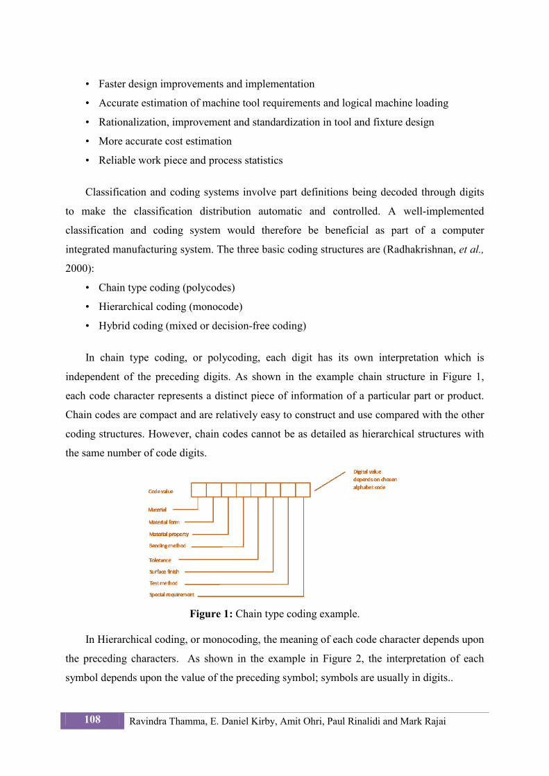
In chain type coding, or polycoding, each digit has its own interpretation which is
independent of the preceding digits. As shown in the example chain structure in Figure 1,
each code character represents a distinct piece of information of a particular part or product.
Chain codes are compact and are relatively easy to construct and use compared with the other
coding structures. However, chain codes cannot be as detailed as hierarchical structures with
the same number of code digits.
Figure 1: Chain type coding example.
In Hierarchical coding, or monocoding, the meaning of each code character depends upon
the preceding characters. As shown in the example in Figure 2, the interpretation of each
symbol depends upon the value of the preceding symbol; symbols are usually in digits..
108 Ravindra Thamma, E. Daniel Kirby, Amit Ohri, Paul Rinalidi and Mark Rajai
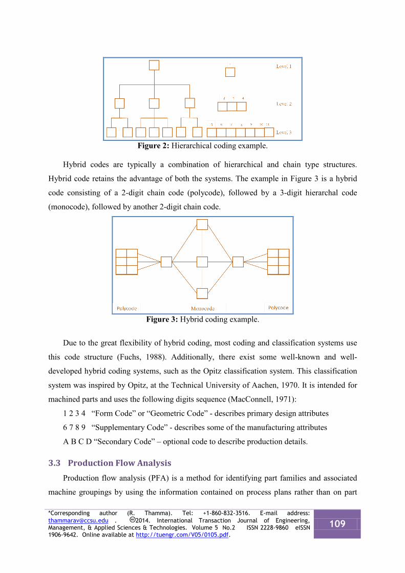
Figure 2: Hierarchical coding example.
Hybrid codes are typically a combination of hierarchical and chain type structures.
Hybrid code retains the advantage of both the systems. The example in Figure 3 is a hybrid
code consisting of a 2-digit chain code (polycode), followed by a 3-digit hierarchal code
(monocode), followed by another 2-digit chain code.
Figure 3: Hybrid coding example.
Due to the great flexibility of hybrid coding, most coding and classification systems use
this code structure (Fuchs, 1988). Additionally, there exist some well-known and well-
developed hybrid coding systems, such as the Opitz classification system. This classification
system was inspired by Opitz, at the Technical University of Aachen, 1970. It is intended for
machined parts and uses the following digits sequence (MacConnell, 1971):
1 2 3 4 “Form Code” or “Geometric Code” - describes primary design attributes
6 7 8 9 “Supplementary Code” - describes some of the manufacturing attributes
A B C D “Secondary Code” – optional code to describe production details.
3.3 Production Flow Analysis Production flow analysis (PFA) is a method for identifying part families and associated
machine groupings by using the information contained on process plans rather than on part
*Corresponding author (R. Thamma). Tel: +1-860-832-3516. E-mail address: [email protected] . 2014. International Transaction Journal of Engineering, Management, & Applied Sciences & Technologies. Volume 5 No.2 ISSN 2228-9860 eISSN 1906-9642. Online available at http://tuengr.com/V05/0105.pdf.
109
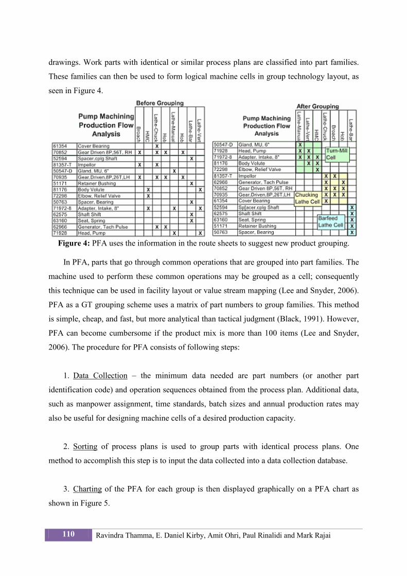
drawings. Work parts with identical or similar process plans are classified into part families.
These families can then be used to form logical machine cells in group technology layout, as
seen in Figure 4.
Figure 4: PFA uses the information in the route sheets to suggest new product grouping.
In PFA, parts that go through common operations that are grouped into part families. The
machine used to perform these common operations may be grouped as a cell; consequently
this technique can be used in facility layout or value stream mapping (Lee and Snyder, 2006).
PFA as a GT grouping scheme uses a matrix of part numbers to group families. This method
is simple, cheap, and fast, but more analytical than tactical judgment (Black, 1991). However,
PFA can become cumbersome if the product mix is more than 100 items (Lee and Snyder,
2006). The procedure for PFA consists of following steps:
1. Data Collection – the minimum data needed are part numbers (or another part
identification code) and operation sequences obtained from the process plan. Additional data,
such as manpower assignment, time standards, batch sizes and annual production rates may
also be useful for designing machine cells of a desired production capacity.
2. Sorting of process plans is used to group parts with identical process plans. One
method to accomplish this step is to input the data collected into a data collection database.
3. Charting of the PFA for each group is then displayed graphically on a PFA chart as
shown in Figure 5.
110 Ravindra Thamma, E. Daniel Kirby, Amit Ohri, Paul Rinalidi and Mark Rajai
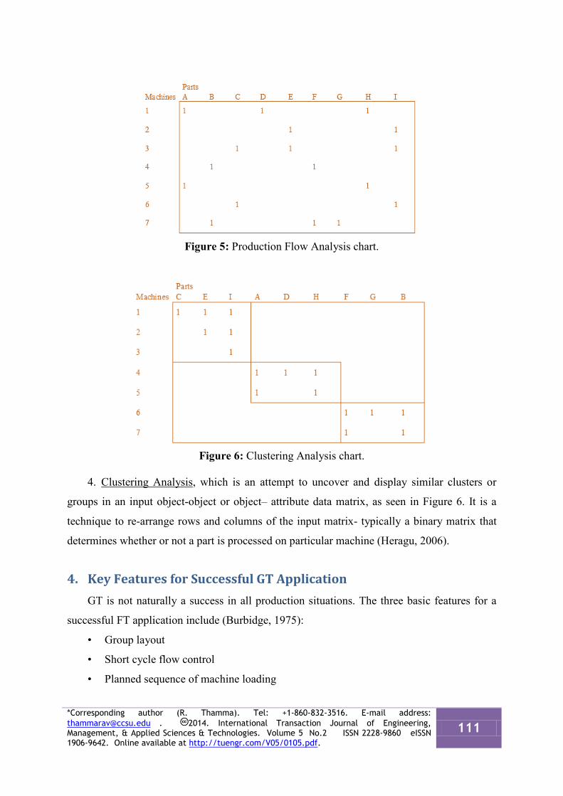
Figure 5: Production Flow Analysis chart.
Figure 6: Clustering Analysis chart.
4. Clustering Analysis, which is an attempt to uncover and display similar clusters or
groups in an input object-object or object– attribute data matrix, as seen in Figure 6. It is a
technique to re-arrange rows and columns of the input matrix- typically a binary matrix that
determines whether or not a part is processed on particular machine (Heragu, 2006).
4. Key Features for Successful GT Application GT is not naturally a success in all production situations. The three basic features for a
successful FT application include (Burbidge, 1975):
• Group layout
• Short cycle flow control
• Planned sequence of machine loading
*Corresponding author (R. Thamma). Tel: +1-860-832-3516. E-mail address: [email protected] . 2014. International Transaction Journal of Engineering, Management, & Applied Sciences & Technologies. Volume 5 No.2 ISSN 2228-9860 eISSN 1906-9642. Online available at http://tuengr.com/V05/0105.pdf.
111
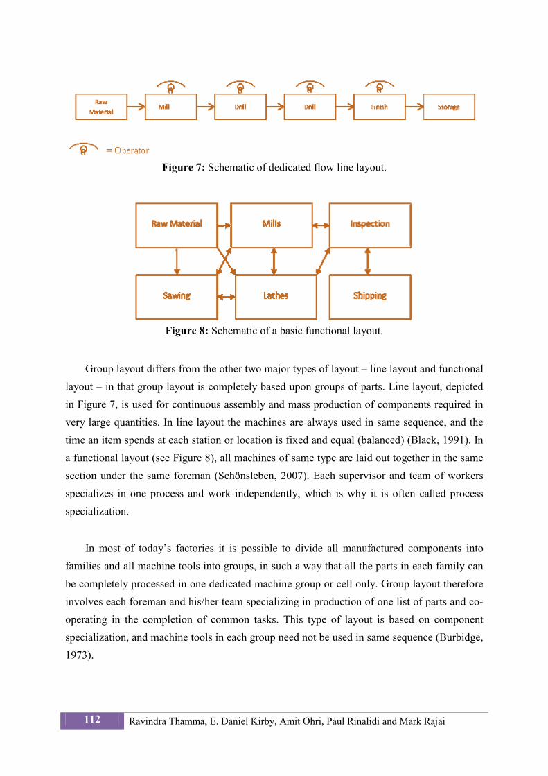
Figure 7: Schematic of dedicated flow line layout.
Figure 8: Schematic of a basic functional layout.
Group layout differs from the other two major types of layout – line layout and functional layout – in that group layout is completely based upon groups of parts. Line layout, depicted in Figure 7, is used for continuous assembly and mass production of components required in very large quantities. In line layout the machines are always used in same sequence, and the time an item spends at each station or location is fixed and equal (balanced) (Black, 1991). In a functional layout (see Figure 8), all machines of same type are laid out together in the same section under the same foreman (Schönsleben, 2007). Each supervisor and team of workers specializes in one process and work independently, which is why it is often called process specialization.
In most of today’s factories it is possible to divide all manufactured components into families and all machine tools into groups, in such a way that all the parts in each family can be completely processed in one dedicated machine group or cell only. Group layout therefore involves each foreman and his/her team specializing in production of one list of parts and co-operating in the completion of common tasks. This type of layout is based on component specialization, and machine tools in each group need not be used in same sequence (Burbidge, 1973).
112 Ravindra Thamma, E. Daniel Kirby, Amit Ohri, Paul Rinalidi and Mark Rajai
5. Application of Group Technology The first step in quality control must be to control design, since a good design should
make it possible for the product, to be manufactured by current equipment with a high level of quality maintained. This means that a good design should contribute something to increase quality while reducing costs. GT can be a tool to help designers reach these two conflicting goals.
Basically, the cluster algorithms of GT can be classified into two major classes. A design- oriented approach relies on the design features of parts to perform the necessary analysis. The production-oriented approach, on the other hand, is based on routing information to group parts or machine (Kroll and Wang, 1994).
The objectives or constraints under which the GT system design problem is typically
tackled are as follows (Vakharia and Wemmerlöv, 1990):
• Minimize the intercellular materials handling cost (or maximize cell
independence). A primary focus of GT is to identify cells where the between-cell
interaction is restricted.
• Minimize investment in equipment. In reorganizing a job shop into a GT cell
system, there is typically an increase in the number of machines required. Hence,
this objective focuses on minimizing the additional investment in such equipment.
• Maintain acceptance equipment utilization levels. A cell system design is feasible
if the utilization of equipment in each cell is less than the maximum acceptable
level.
• Identify the cells of reasonable size. The size of the GT cell will impact how
easily the cell can be managed and controlled. Hence cells identified should not
contain more than a specified number of machines.
6. Benefits of GT Toward Automation Since manufacturing costs are major determinants of ultimate product costs, it is not
surprising that optimizing the manufacturing process by grouping parts together can produce a significant return on investment.
*Corresponding author (R. Thamma). Tel: +1-860-832-3516. E-mail address: [email protected] . 2014. International Transaction Journal of Engineering, Management, & Applied Sciences & Technologies. Volume 5 No.2 ISSN 2228-9860 eISSN 1906-9642. Online available at http://tuengr.com/V05/0105.pdf.
113
By analyzing a part database, it is possible to identify groups of parts that are similar from manufacturing point of view. This requires a production-oriented grouping method, such as Opitz classification and coding or PFA (Modak, et al., 2011). Having done that, the next step is standardization – by manufacturing engineers – of manufacturing processes for group of similar parts. This manufacturing standardization leads to a best practice approach to making parts, and provides the basis for work instructions to the shop floor.
The grouping of parts into families can then lead to the development of a new type of
mass production and the introduction of mass production methods for those families of parts. The costs associated with classification and standardization therefore do not have to be applied to lot sizes of just a few parts; they can be given to families of parts that may run much larger numbers (Houtzeel, 2001). The following are some of the major benefits of GT:
• Faster implementation of design and process improvements
• Reduction of inventory (incoming, in-process and finished)
• Reduction in wait time
• Reduction in production planning effort
• Simplification of parts and their manufacturing processes
• Component standardization
• Reduction of overall production cost
• Higher accuracy of estimates
• Improvement in employee morale
• Improvement in space utilization
• Setup time reduction
• Higher productivity
• Improvement in quality
• Improvement in material flow
Utilizing GT captures certain advantages such as reduced setup times, reduced in-process inventories, improved product quality, shorter lead time, reduced tool requirements, improved productivity, and better overall control of operations. It is these benefits that allow GT to pave the road towards automation. For example, if there is a single family’s flow of parts and/or products that is consistent and controlled, we can put in place a reliable and repeatable way of handling these materials via robotics and autonomous vision systems with pick-and place capabilities. This process will ensure that our incoming parts are being automatically
114 Ravindra Thamma, E. Daniel Kirby, Amit Ohri, Paul Rinalidi and Mark Rajai
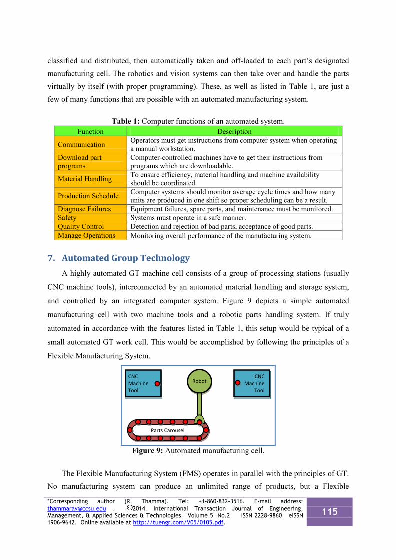
classified and distributed, then automatically taken and off-loaded to each part’s designated manufacturing cell. The robotics and vision systems can then take over and handle the parts virtually by itself (with proper programming). These, as well as listed in Table 1, are just a few of many functions that are possible with an automated manufacturing system.
Table 1: Computer functions of an automated system.
Function Description
Communication Operators must get instructions from computer system when operating a manual workstation.
Download part programs
Computer-controlled machines have to get their instructions from programs which are downloadable.
Material Handling To ensure efficiency, material handling and machine availability should be coordinated.
Production Schedule Computer systems should monitor average cycle times and how many units are produced in one shift so proper scheduling can be a result.
Diagnose Failures Equipment failures, spare parts, and maintenance must be monitored. Safety Systems must operate in a safe manner. Quality Control Detection and rejection of bad parts, acceptance of good parts. Manage Operations Monitoring overall performance of the manufacturing system.
7. Automated Group Technology A highly automated GT machine cell consists of a group of processing stations (usually
CNC machine tools), interconnected by an automated material handling and storage system,
and controlled by an integrated computer system. Figure 9 depicts a simple automated
manufacturing cell with two machine tools and a robotic parts handling system. If truly
automated in accordance with the features listed in Table 1, this setup would be typical of a
small automated GT work cell. This would be accomplished by following the principles of a
Flexible Manufacturing System.
Figure 9: Automated manufacturing cell.
The Flexible Manufacturing System (FMS) operates in parallel with the principles of GT. No manufacturing system can produce an unlimited range of products, but a Flexible
CNC Machine Tool
CNC Machine
Tool
Parts Carousel
Robot
*Corresponding author (R. Thamma). Tel: +1-860-832-3516. E-mail address: [email protected] . 2014. International Transaction Journal of Engineering, Management, & Applied Sciences & Technologies. Volume 5 No.2 ISSN 2228-9860 eISSN 1906-9642. Online available at http://tuengr.com/V05/0105.pdf.
115
Manufacturing Cell (FMC) is capable of producing single part family or a limited range of part families. This flexibility is a key advantage of an FMC – the ability to cope with changes in part design, changes in production, equipment malfunctions, and variations within a part family. These principles – especially variation within a part family – imply common characteristics of GT and FMS.
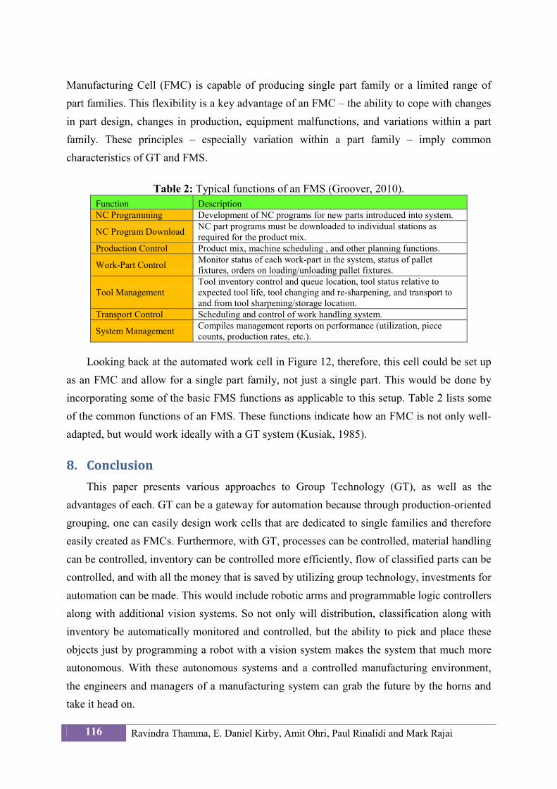
Table 2: Typical functions of an FMS (Groover, 2010).
Function Description NC Programming Development of NC programs for new parts introduced into system.
NC Program Download NC part programs must be downloaded to individual stations as required for the product mix.
Production Control Product mix, machine scheduling , and other planning functions.
Work-Part Control Monitor status of each work-part in the system, status of pallet fixtures, orders on loading/unloading pallet fixtures.
Tool Management Tool inventory control and queue location, tool status relative to expected tool life, tool changing and re-sharpening, and transport to and from tool sharpening/storage location.
Transport Control Scheduling and control of work handling system.
System Management Compiles management reports on performance (utilization, piece counts, production rates, etc.).
Looking back at the automated work cell in Figure 12, therefore, this cell could be set up
as an FMC and allow for a single part family, not just a single part. This would be done by incorporating some of the basic FMS functions as applicable to this setup. Table 2 lists some of the common functions of an FMS. These functions indicate how an FMC is not only well-adapted, but would work ideally with a GT system (Kusiak, 1985).
8. Conclusion This paper presents various approaches to Group Technology (GT), as well as the
advantages of each. GT can be a gateway for automation because through production-oriented grouping, one can easily design work cells that are dedicated to single families and therefore easily created as FMCs. Furthermore, with GT, processes can be controlled, material handling can be controlled, inventory can be controlled more efficiently, flow of classified parts can be controlled, and with all the money that is saved by utilizing group technology, investments for automation can be made. This would include robotic arms and programmable logic controllers along with additional vision systems. So not only will distribution, classification along with inventory be automatically monitored and controlled, but the ability to pick and place these objects just by programming a robot with a vision system makes the system that much more autonomous. With these autonomous systems and a controlled manufacturing environment, the engineers and managers of a manufacturing system can grab the future by the horns and take it head on.
116 Ravindra Thamma, E. Daniel Kirby, Amit Ohri, Paul Rinalidi and Mark Rajai
9. References Black, J.T. (1991). The Design of the Factory with a Future. New York: McGraw-Hill.
Burbidge, J. L. (1973). AIDA and Group Technology. International Journal of Production Research. 11(4), 315-324.
Burbidge, J. L. (1975). The Introduction of Group Technology. New York: Wiley.
Fuchs, J. H. (1988). The Prentice Hall Illustrated Handbook of Advanced Manufacturing Methods. Englewood Cliffs, NJ: Prentice Hall.
Groover, M. P. (2008). Automation, Production Systems, and Computer-Integrated Manufacturing. Upper Saddle River, NJ: Pearson Education.
Groover, M. P. (2010). Fundamentals of Modern Manufacturing: Materials, Processes, and Systems. New York. John Wiley & Sons.
Heragu, S. S. (2006). Facilities Design. Lincoln, NE: iUniverse.
Houtzeel, A. (2001). Chapter 17.6: Group Technology. In Zandin, K. & Maynard, H. (ed.s) Maynard's Industrial Engineering Handbook. New York: McGraw-Hill.
Kamrani, A. K. & Salhieh, S. M. (2002). Product Design for Modularity. Norwell, MA: Kluwer.
Kaparthi, S. & Suresh, N. (1991). A Neural Network System For Shape-Based Classification and Coding of Rotational Parts. International Journal of Production Research, 29(9), 1771- 1784.
Kroll, D. & Wang, X. (1994) Using Group Technology to Improve Quality and Response Time. Industrial Management, 36(4), 21-22.
Kusiak, A. (1985). The part families’ problem in flexible manufacturing systems. Annals of Operations Research. 3(6), 279-300.
Kusiak, A. (1987). The Generalized Group Technology Concept. International Journal of Production Research, 25(4), 561-569.
Lee, Q. & Snyder, B. (2006). The Strategos Guide to Value Stream and Process Mapping: Genesis of Manufacturing Strategy. Bellingham, WA: Enna Products Corp.
Luong, L. H. S., Kazerooni, M., & Abhary, K. (2001). Genetic Algorithms in Manufacturing System Design. In J. Wang & A. Kusiak (Eds.), Computational Intelligence in Manufacturing Handbook (6-1 – 6-19). Boca Raton, FL: CRC Press.
MacConnell, W. (1971). Classification and Coding: An Introduction and Review of Classification and Coding Systems. London: British Institute of Management.
Modak, M., Ghosh, T. & Dan, P. K. (2011). Solving component family identification problems on manufacturing shop floor. International Journal of Advancements in Technology. 2(1), 39-56.
Quintana, G., Ciurana, J., & G-Romeu, M. L. (2008). Decision Support Tool for Blank *Corresponding author (R. Thamma). Tel: +1-860-832-3516. E-mail address: [email protected] . 2014. International Transaction Journal of Engineering, Management, & Applied Sciences & Technologies. Volume 5 No.2 ISSN 2228-9860 eISSN 1906-9642. Online available at http://tuengr.com/V05/0105.pdf.
117
Selection in Workshop Machining Processes, Engineering Computations, 25(2), 140-154.
Radhakrishnan, P., Subramanyan, S., & Raju, V. (2000). CAD/CAM/CIM. New Delhi, India: New Age International.
Rajput, R. K. (2007). A Textbook of Manufacturing Technology: (Manufacturing Processes). New Delhi: Laxmi Publications.
Schönsleben, P. (2007). Integral Logistics Management. Boca Raton, FL: Auerbach Publications.
Suresh, N. C. & Kay, J. M. (1998). Technology and Cellular Manufacturing. Norwell, MA: Kluwer.
Tatikonda, M. V. & Wemmerlöv, U. (1992). Adoption and Implementation of Group Technology Classification and Coding Systems : Insights from Seven Case Studies. International Journal of Production Research, 30(9), 2087-2110.
Vakharia, A. J. and Wemmerlöv, U. (1990). Designing a cellular manufacturing system: A materials flow approach based on operation sequences. IIE Transactions, 22 (1), 84-97.
Dr. Ravindra Thamma is currently an Associate Professor of Manufacturing and Construction Management Department Engineering at Central Connecticut State University. Dr. Thamma received his PhD from Iowa State University. His teaching and research interests are robotics, linear control systems and intelligent system.
Dr. E. Daniel Kirby earned his Ph.D. from Iowa State University in 2005, his major research being in adaptive control of machining processes. Prior to that, he spent five years in manufacturing as an industrial engineer. He is currently an associate professor in the Department of Manufacturing and Construction Management at Central Connecticut State University, where he teaches courses in basic and advanced manufacturing, industrial materials, robotics and mechatronics, and occupational safety.
Amit Ohri received his Bachelor of Science in Mechanical at Gulbarga University in India. For last thirteen years, he has been working as a “Quality Engineer” in manufacturing companies. Amit is pursuing his Master of Engineering in Engineering Technology and took an admission in Central State University, Connecticut.
Paul Rinaldi is a graduate student in the Masters of Science for Engineering Technology at Central Connecticut State University, New Britain, CT.
Dr. Mark Rajai is a full time faculty in the Department of Manufacturing System Engineering and Management at California State University Northridge. Dr. Rajai is also President of International Association of Journals and Conferences and has published numerous books and journal articles.
Peer Review: This article has been internationally peer-reviewed and accepted for publication according to the guidelines in the journal’s website.
118 Ravindra Thamma, E. Daniel Kirby, Amit Ohri, Paul Rinalidi and Mark Rajai