Embed Size (px)
Citation preview

iTM plus adaptor
ModelDCM601A72
Installation Manual
Disclosure
To the User in USA
Part 15 of FCC
Note: This equipment has been tested and found to comply with the limits for a Class B digital device, pursuant to part 15 of the FCC Rules. These limits are designed to provide reasonable protection against harmful interference in a residential installation. This equip-ment generates, uses and can radiate radio frequency energy and, if not installed and used in accordance with the instructions, may cause harmful interference to radio communica-tions. However, there is no guarantee that interference will not occur in a particular installa-tion. If this equipment does cause harmful interference to radio or television reception, which can be determined by turning the equipment off and on, the user is encouraged to try to correct the interference by one or more of the following measures:
- Reorient or relocate the receiving antenna.- Increase the separation between the equipment and receiver.- Connect the equipment into an outlet on a circuit different from that to which the receiver
is connected.- Consult the dealer or an experienced radio/TV technician for help.
FCC CAUTIONChanges or modifications not expressly approved by the party responsible for compliance could void the user’s authority to operate the equipment.
To the User in CANADA
Canadian ICES-003
This Class B digital apparatus complies with Canadian ICES-003.Cet appareil numérique de la classe B est conforme à la norme NMB-003 du Canada.

Installation Manual 3P291714-4BDCM601A72 iTM plus adaptor
3English
All phases of the field-installation, including, but not limited to, electrical, piping, safety, etc. must be in accordance with manufacturer’s instructions and must comply with national, state, provincial and local codes.
Read these SAFETY CONSIDERATIONS carefully before installing the controller. After completing the installation, ensure that the controller operates properly during the startup operation.Train the customer to operate and maintain the controller. Inform customers that they should store this Installation Manual with the User’s Manual for future reference.Always use a licensed installer or contractor to install this product. Improper installation can result in electrical shock, fire, or explosion.Meanings of WARNING, CAUTION, and NOTE Symbols.
WARNING Indicates a potentially hazardous situation which, if not avoided, could result in death or serious injury.
CAUTIONIndicates a potentially hazardous situation which, if not avoided, may result in minor or moderate injury. It may also be used to alert against unsafe practices.
NOTE Indicates situations that may result in equipment or prop-erty-damage accidents only.
WARNING • Only qualified personnel must carry out the installation work.
• Consult your Daikin dealer regarding relocation and reinstallation of the con-troller. Improper installation work may result in electric shocks or fire.
• Install the controller in accordance with the instructions in the installation man-ual. Improper installation may cause electrical shocks or fire.
• Use only specified accessories and parts for installation work. Failure to use specified parts may result in electric shocks, fire, or the unit falling.
• Do not disassemble, reconstruct, or repair.Electric shock or fire may occur.
• Make sure that all wiring is secured, that specified wires are used, and that no external forces act on the terminal connections or wires. Improper connections or installation may result in fire.
• Before touching electrical parts, turn off the unit.
Safety Considerations

4 Installation Manual 3P291714-4BDCM601A72 iTM plus adaptor
English
CAUTION • Keep water out of the controller. • To avoid electric shock due to entry of water or insects, fill the wiring through-hole with putty.
• Do not wash the controller with water as it may result in electrical shocks or fire.
• Do not touch the controller buttons with wet fingers. Touching the buttons with wet fingers can cause an electric shock.
• Do not install the controller in the following locations:(a) Where a mineral oil mist or oil spray or vapor is produced, for example, in a
kitchen.Plastic parts may deteriorate and fall off.
(b) Where corrosive gas, such as sulfurous acid gas, is produced. (c) Near machinery emitting electromagnetic waves.
Electromagnetic waves may disturb the operation of the control system and cause the unit to malfunction.
(d) Where flammable gas may leak, where there is carbon fiber or ignitable dust suspensions in the air, or where volatile flammables such as thinner or gaso-line are handled. Operating the unit in such conditions can cause a fire.
(e) High temperature area or directly flamed point. Heating and/or fire can occur.
(f) Moist area, where there is exposure to water. If water enters the inside of the controller, it may cause electric shock and electrical components may fail.
NOTE • Install the control wires for the controller at least 3.5 feet (1 meter) away from televisions or radios to prevent image interference or noise. Depending on the radio waves, a distance of 3.5 feet (1 meter) may not be sufficient to eliminate the noise.

Installation Manual 3P291714-4BDCM601A72 iTM plus adaptor
5English
Contents
1 Before Installation ................................................................................................... 7
1.1 Checking that all accessories are included ................................................................................ 7
1.2 Understanding external dimensions .......................................................................................... 8
1.3 Understanding where terminals and switches are located ........................................................ 8
1.3.1 Front face ......................................................................................................................... 8
1.4 Determining installation place .................................................................................................. 10
1.4.1 Installation place and mounting direction ...................................................................... 10
1.4.2 Environmental conditions .............................................................................................. 10
1.4.3 Required space ............................................................................................................. 11
2 Electric wiring ........................................................................................................ 12
2.1 Connecting intelligent Touch Manager ..................................................................................... 13
2.1.1 Terminal location and schematic wiring diagram ........................................................... 13
2.1.2 Wiring specifications ...................................................................................................... 13
2.1.3 Address setup and termination resistor ......................................................................... 14
2.2 Connecting DIII-NET-compatible air conditioning equipment ................................................... 15
2.2.1 Terminal location and schematic wiring diagram ........................................................... 16
2.2.2 Wiring specifications ...................................................................................................... 17
2.2.3 Precautions for using multiple centralized controllers .................................................... 17
2.3 Connecting an emergency stop input device or power meter .................................................. 18
2.3.1 Terminal location and schematic wiring diagram ........................................................... 19
2.3.2 Wiring specifications ...................................................................................................... 19
2.4 Connecting power supply ........................................................................................................ 20
2.4.1 Terminal location and schematic wiring diagram ........................................................... 20
2.4.2 Wiring specifications ...................................................................................................... 21
3 Secure installation of iTM plus adaptor .............................................................. 22
3.1 Screw mounting to control enclosure ....................................................................................... 22
3.1.1 Installation procedure .................................................................................................... 22
3.2 DIN rail mounting ..................................................................................................................... 23
3.2.1 Removal from DIN rail ................................................................................................... 24
4 Setting DIII-NET address for each air conditioner .............................................. 25
4.1 Names of buttons and display areas ....................................................................................... 25
4.1.1 Setting address with wired remote controller ................................................................. 26
4.1.2 Setting address with navigation remote controller ......................................................... 28
4.1.3 Setting an unique address to each unit (when Power Proportional Distribution (option) is used) ... 29
6 Installation Manual 3P291714-4BDCM601A72 iTM plus adaptor
English
5 Quick Operation Guide ......................................................................................... 30
5.1 Viewing target area and management point information in list format ..................................... 30
5.2 Displaying areas and management points ............................................................................... 30
5.3 Starting/stopping an area or management point ..................................................................... 31

Installation Manual 3P291714-4BDCM601A72 iTM plus adaptor
7English
1 Before Installation
Before you start installing the iTM plus adaptor, complete the following checks:
• Check that the iTM plus adaptor comes with all accessories.
• Understand where the terminals and switches of the iTM plus adaptor are located.
• Make sure that an appropriate space for installing the iTM plus adaptor is available.
1.1 Checking that all accessories are included
Based on the following accessory list, check that all accessories for the iTM plus adaptor are included. If there is any missing or defective part, contact your DAIKIN dealer where you purchased the product.
<Accessories included with iTM plus adaptor>
A B
C
D
d-1
a-1
b-1
c-1
A (a-1) iTM plus adaptor body (1 pc.)
B (b-1) Round-head wood screw (φ3.5×16), 4 pcs.
C (c-1) Clamp, 1 pc.
D (d-1) Installation manual (This manual), 1 pc.

8 Installation Manual 3P291714-4BDCM601A72 iTM plus adaptor
English
1.2 Understanding external dimensions • iTM plus adaptor body
5-7/
8
4-23
/32
2-11
/16
2-21
/32
2-1/
16
6-5/16
2-13/32
2-13/32
(in.)
1/4 1/4
5/32
5/32
1/4
5/32
1/4
5-1/2
5/32
1.3 Understanding where terminals and switches are located
Understand the arrangement of terminals and switches on the unit and draw up an effi-cient work plan. For connection details including the cable type, terminal size, and wiring precautions, refer to “2. Electric wiring”.
1.3.1 Front face
All the terminals used during installation are located on the front face of the iTM plus adaptor. The power supply terminal is protected with a cover for safety. Remove the screw to detach the cover.
Besides the terminals, there are several switches and LEDs on the front face of the iTM plus adaptor.

Installation Manual 3P291714-4BDCM601A72 iTM plus adaptor
9English
<Front face of iTM plus adaptor>
A
F I
J K L M N
G H
B C D
PO
WE
R
100-
240V
~50
/60H
z
LN E
A [plus ADP IF] The terminal for connecting with the intelligent Touch Manager or other iTM plus adaptor.
B [DIII] The communication line connection terminals for “DIII-NET”, which enables communications with DAIKIN’s air conditioning equipment.
C [Di] The terminals for stopping air conditioners according to the external signal in an emergency, for connecting a power meter to calculate the electricity usage of indi-vidual indoor air conditioners, or for other operations.
D [RESERVE] No Use.
E [POWER] The power line connection terminals. These terminals are covered with a protective cover. A power supply voltage of 24 VAC (at 60 Hz) is required. Near the terminal block, there is a blue resin cable mount for securing the power supply cable with the clamp.
F [plus ADP ADDRESS] The switch for selecting the address of the iTM plus adaptor. For each iTM plus adaptor, set a unique number between 2 to 8.
G [TERM] The switch used to activate the termination resistor of the terminal iTM plus adaptor in the connection with other iTM plus adaptor or the intelligent Touch Man-ager (using the plus ADP IF terminal). (Factory default: OFF)
H [DIII MASTER] The switch for setting “MASTER” or “SLAVE” for the iTM plus adaptor when there are multiple DIII-NET centralized controllers such as the intelligent Touch Manager are used. (Factory default: MASTER)
I [RESET//] The switch for restarting the iTM plus adaptor.
J [Tx] (Green) The indicator that indicates when on that data is being sent to the intel-ligent Touch Manager.
K [Rx] (Orange) The indicator that indicates when on that data is being received from the intelligent Touch Manager.
L [DIII MONITOR] (Yellow) This LED blinks when the DIII-NET communication is per-formed.
M [CPU ALIVE] (Green) This LED blinks when the CPU operates properly. For details on LED operations, refer to the “LED status and operation table” shown on the next page.
N [ALARM] (Red) This LED is lit or blinks when there is a failure. For details on LED operations, refer to the “LED status and operation table” shown on the next page.

10 Installation Manual 3P291714-4BDCM601A72 iTM plus adaptor
English
The table below shows the status of the CPU ALIVE/ALARM LED when the iTM plus adaptor is operating normally or failed.
NOTE
[LED status and operation table]
Operating condition CPU ALIVE ALARM
Normal Blink Off
Hardware failure Off On
Address failure On On
Communication failure between intelligent Touch Manager and iTM
plus adaptorOn Blink
1.4 Determining installation place
Be sure to install the iTM plus adaptor in a place that meets the conditions described in 1.4.1 to 1.4.3.
1.4.1 Installation place and mounting direction
Below are the description of the installation place and mounting direction. Be sure to confirm.
• Installation place: Indoor, inside control enclosure (which must be lockable or designed to be opened only with a special tool)
• Mounting direction: Vertical only
1.4.2 Environmental conditions
Check that the installation environment meets the following conditions:
• Ambient temperature: 14 to 122 °F
• Ambient humidity: 85% RH or less (without condensation)

Installation Manual 3P291714-4BDCM601A72 iTM plus adaptor
11English
1.4.3 Required space
The figure shown below indicates the space required for installation.
• Make sure that there is a minimum clearance of 25/32 in. between each unit and wiring ducts.
• Multiple iTM plus adaptors can be installed without clearance in the horizontal direction.
<Installation space required for iTM plus adaptor>
Required installa-tion space
1-9/16
1-9/16
25/32
25/32
25/32
(in.)
A
A
6-5/16
5-7/
8
A Wiring duct

12 Installation Manual 3P291714-4BDCM601A72 iTM plus adaptor
English
2 Electric wiring
This chapter describes the procedure for connecting the iTM plus adaptor with intelligent Touch Manager, DIII-NET-compatible air conditioning devices and other equipment.
In addition to air conditioners, the iTM plus adaptor can be connected and work with a wide range of equipment. However, the required connection procedures vary depending on the equipment to be connected. Do not connect more than two wires to the same terminal.
Required proce-dures
• 2.1 Connecting intelligent Touch Manager
• 2.2 Connecting DIII-NET-compatible air conditioning equipment
• 2.4 Connecting power supply
Equipment-spe-cific procedures
• 2.3 Connecting an emergency stop input device or power meter
WARNING
• Do not turn on the power supply before all wire connections are completed. Not doing so may cause an electric shock.
• After the wiring is completed, double-check that all wires are connected cor-rectly before turning on the power supply.
• All field supplied parts and materials, electric works must conform to local codes.
• All wiring must be performed by an authorized electrician.
CAUTION
Provide a cable trap before the terminal block and perform wiring to prevent water entry. Water splashing onto the terminal block may result in an electric shock or fire.
BA
C
A Terminal block
B With trap
C Without trap

Installation Manual 3P291714-4BDCM601A72 iTM plus adaptor
13English
2.1 Connecting intelligent Touch Manager
The iTM plus adaptor is a device that increases the number of air conditioners controlled by the intelligent Touch Manager. It needs to be connected to an intelligent Touch Manager to provide this capability.
2.1.1 Terminal location and schematic wiring diagram
Connect the plus ADP IF terminal of the iTM plus adaptor to the plus ADP IF terminal on the rear face of the intelligent Touch Manager. Note that these terminals have polarity. Be sure to connect the positive wire to the “+” terminal and the negative wire to the “–” termi-nal.
Also, connect the intelligent Touch Manager to the termination of the wiring.
<Terminal location and schematic wiring diagram>
A intelligent Touch Manager (For details, refer to the “intelligent Touch Manager Installation Manual (EM11A018)”.)
B iTM plus adaptor
C plus ADP IF (intelligent Touch Manager)
D plus ADP IF (iTM plus adaptor)
E iTM plus adaptor on which termination resistor must be enabled
2.1.2 Wiring specifications
• Cable type: CPEV or FCPEV cable
• Core thickness: AWG22-19
• Cable length: The overall cable length between the intelligent Touch Manager and the terminal iTM plus adaptor is 164 ft. or less.
• Wiring connection type: sequential connections

14 Installation Manual 3P291714-4BDCM601A72 iTM plus adaptor
English
2.1.3 Address setup and termination resistor
For each iTM plus adaptor, a unique address needs to be set. The number for the intelli-gent Touch Manager is always set to "1". Therefore, the setting range for the iTM plus adaptor is from “2” to “8”. Use the plus ADP ADDRESS switch on the front face of the iTM plus adaptor to set the address.
Moreover, the termination resistor needs to be set for the iTM plus adaptor which is the farthest from the intelligent Touch Manager. To set the termination resistor, change the position of the TERM switch on the front face of the iTM plus adaptor to ON position.
<plus ADP ADDRESS switch and TERM switch>
NOTE
If the two LEDs, CPU ALIVE and ALARM, both light up during power-on after installa-tion, there is a possibility of a problem with the address assignment:
• An invalid address is set. (“0”, “1”, and “9” are not allowed.)
• A duplicate address is used.You must assign a unique address between 2 and 8 for each iTM plus adaptor. Power off the unit once, check and correct the address, and then turn it on again.Check the status of the two LEDs, CPU ALIVE and ALARM.
Installation Manual 3P291714-4BDCM601A72 iTM plus adaptor
15English
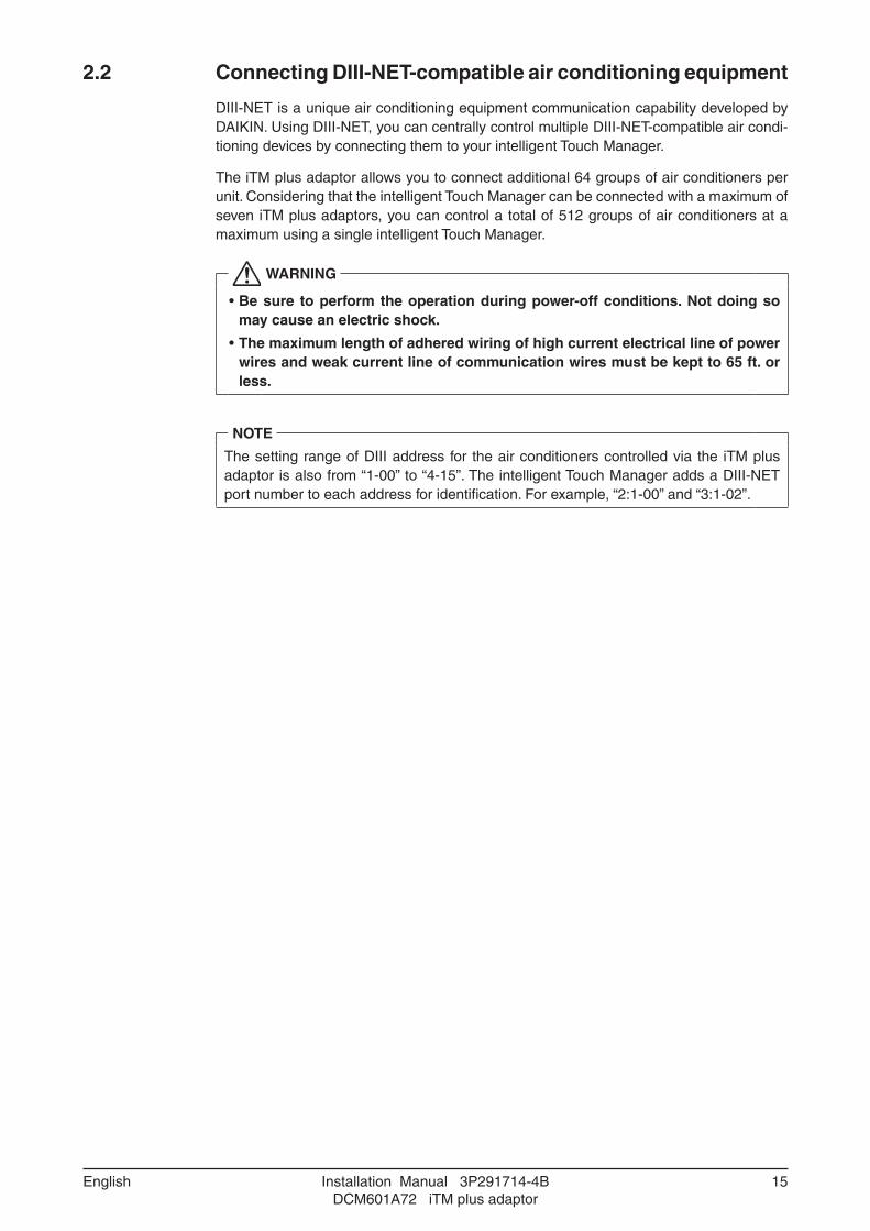
2.2 Connecting DIII-NET-compatible air conditioning equipment
DIII-NET is a unique air conditioning equipment communication capability developed by DAIKIN. Using DIII-NET, you can centrally control multiple DIII-NET-compatible air condi-tioning devices by connecting them to your intelligent Touch Manager.
The iTM plus adaptor allows you to connect additional 64 groups of air conditioners per unit. Considering that the intelligent Touch Manager can be connected with a maximum of seven iTM plus adaptors, you can control a total of 512 groups of air conditioners at a maximum using a single intelligent Touch Manager.
WARNING
• Be sure to perform the operation during power-off conditions. Not doing so may cause an electric shock.
• The maximum length of adhered wiring of high current electrical line of power wires and weak current line of communication wires must be kept to 65 ft. or less.
NOTE
The setting range of DIII address for the air conditioners controlled via the iTM plus adaptor is also from “1-00” to “4-15”. The intelligent Touch Manager adds a DIII-NET port number to each address for identification. For example, “2:1-00” and “3:1-02”.

16 Installation Manual 3P291714-4BDCM601A72 iTM plus adaptor
English
2.2.1 Terminal location and schematic wiring diagram
To connect the DIII-NET communication line, use F1 and F2 terminals with “DIII” mark. The two terminals do not have polarity. The following schematic wiring diagram is an example for when multiple air conditioners are connected.
CAUTION
Make sure that the wires you are connecting to the F1 and F2 terminals are not power wires. Inadvertently connecting power wires to these terminals results in a failure of the air conditioner or iTM plus adaptor.
<Schematic diagram of wiring between air conditioning equipment>
F2F1
F1, F2 P1, P2 F1, F2 P1, P2F1, F2 P1, P2F1, F2 P1, P2F1, F2 P1, P2
F1, F2 F1, F2
F1, F2 P1, P2 F1, F2 P1, P2F1, F2 P1, P2F1, F2 P1, P2F1, F2 P1, P2
F1, F2 F1, F2
E
F
AB C
D D D D D
AB C
D D D D D
A Outdoor unit
B OUT - OUT communication (terminal)
C IN - OUT communication (terminal)
D Indoor unit
E A maximum of 16 indoor units can be connected per remote controller group.
F A maximum of 64 remote controller groups (128 indoor units) can be connected for one DIII-NET. When the power proportional distribution is applied, the maximum num-ber of indoor units is 64.

Installation Manual 3P291714-4BDCM601A72 iTM plus adaptor
17English
NOTE
• What’s a remote controller group?A single remote controller can simultaneously control a maximum of 16 indoor units. This capability is referred to as group control. A remote controller group is a group of indoor units controlled under the same remote controller.
[Schematic diagram of remote controller group]
F1, F2 P1, P2 F1, F2 P1, P2 F1, F2 P1, P2 F1, F2 P1, P2
A
A Max.16 Indoor units
2.2.2 Wiring specifications
• Cable type: 2-core vinyl-insulated vinyl-sheathed cable/vinyl cabtyre cable or 2-core shielded cable
• Core thickness: AWG18-16
• Terminal treatment: Use a round crimp-type terminal (M3) with insulating sleeve.
CAUTION
• Do not use multicore cables with three or more cores.
• When using a shielded cable, connect only one end of the cable to the ground.
• Keep the DIII-NET communication wiring at least 1-31/32 in. away from power supply wiring.
• The maximum wiring length is 3280 ft. and total wiring length is 6561 ft. or less. When using a shielded wire, the total wiring length is limited to 4921 ft. or less.
2.2.3 Precautions for using multiple centralized controllers
The “centralized controller” refers to the equipment (e.g. the intelligent Touch Manager) that control multiple air conditioners. Besides the intelligent Touch Manager, the DAIKIN's product portfolio includes a wide range of centralized controllers suitable for different applications or building sizes, which can be used in combination to construct an optimal air conditioning control system.
If multiple centralized controllers are connected on the DIII-NET network, you must set MASTER and SLAVE relationship for those controllers. Assign only one of those controllers to MASTER, and other controllers to SLAVE.
The iTM plus adaptor is set to MASTER by default. Change the setting to SLAVE in any of the following cases:
• Where Interface for use in BACnet is installed in parallel.
• Where Interface for use in LONWORKS is installed in parallel.
• If there is another intelligent Touch Manager or iTM plus adaptor which is assigned to MASTER.
18 Installation Manual 3P291714-4BDCM601A72 iTM plus adaptor
English
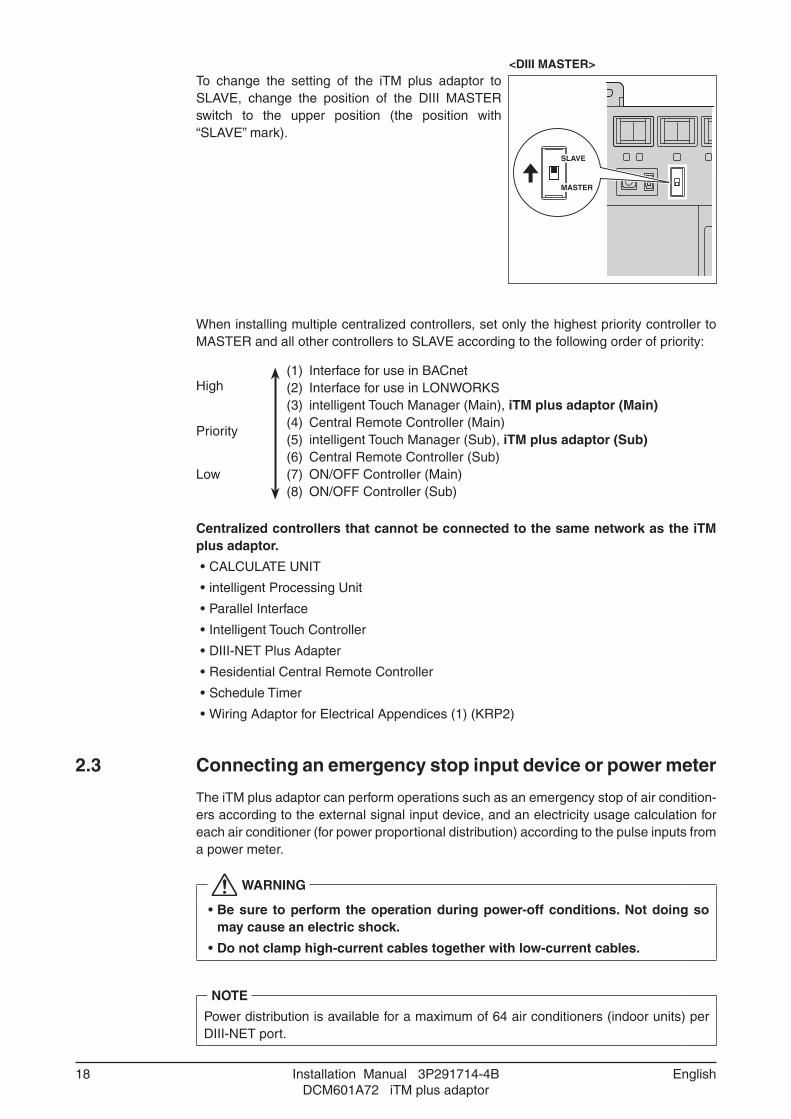
<DIII MASTER>To change the setting of the iTM plus adaptor to SLAVE, change the position of the DIII MASTER switch to the upper position (the position with “SLAVE” mark).
SLAVE
MASTER
When installing multiple centralized controllers, set only the highest priority controller to MASTER and all other controllers to SLAVE according to the following order of priority:
High(1) Interface for use in BACnet(2) Interface for use in LONWORKS(3) intelligent Touch Manager (Main), iTM plus adaptor (Main)(4) Central Remote Controller (Main)(5) intelligent Touch Manager (Sub), iTM plus adaptor (Sub)(6) Central Remote Controller (Sub)(7) ON/OFF Controller (Main)(8) ON/OFF Controller (Sub)
Priority
Low
Centralized controllers that cannot be connected to the same network as the iTM plus adaptor.
• CALCULATE UNIT
• intelligent Processing Unit
• Parallel Interface
• Intelligent Touch Controller
• DIII-NET Plus Adapter
• Residential Central Remote Controller
• Schedule Timer
• Wiring Adaptor for Electrical Appendices (1) (KRP2)
2.3 Connecting an emergency stop input device or power meter
The iTM plus adaptor can perform operations such as an emergency stop of air condition-ers according to the external signal input device, and an electricity usage calculation for each air conditioner (for power proportional distribution) according to the pulse inputs from a power meter.
WARNING
• Be sure to perform the operation during power-off conditions. Not doing so may cause an electric shock.
• Do not clamp high-current cables together with low-current cables.
NOTE
Power distribution is available for a maximum of 64 air conditioners (indoor units) per DIII-NET port.
Installation Manual 3P291714-4BDCM601A72 iTM plus adaptor
19English
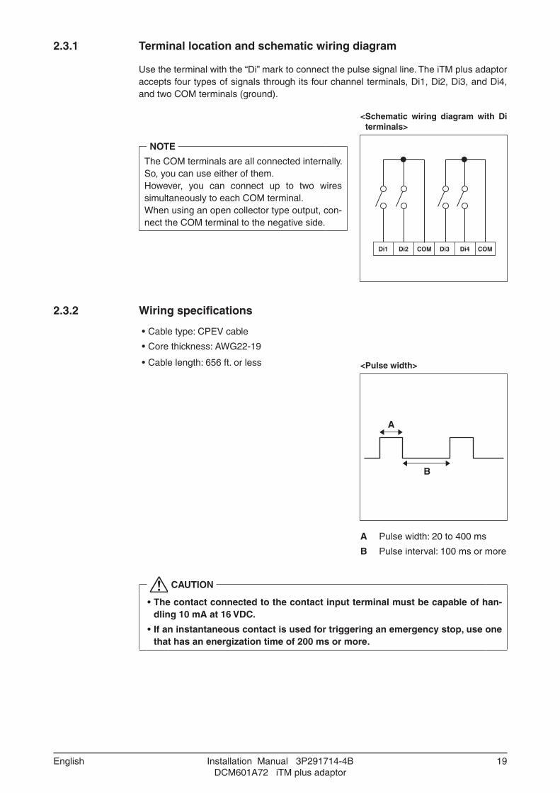
2.3.1 Terminal location and schematic wiring diagram
Use the terminal with the “Di” mark to connect the pulse signal line. The iTM plus adaptor accepts four types of signals through its four channel terminals, Di1, Di2, Di3, and Di4, and two COM terminals (ground).
< Schematic wiring diagram with Di terminals>
NOTE
The COM terminals are all connected internally. So, you can use either of them.However, you can connect up to two wires simultaneously to each COM terminal.When using an open collector type output, con-nect the COM terminal to the negative side.
Di1 Di2 COM Di3 Di4 COM
2.3.2 Wiring specifications
• Cable type: CPEV cable
• Core thickness: AWG22-19
• Cable length: 656 ft. or less <Pulse width>
A
B
A Pulse width: 20 to 400 ms
B Pulse interval: 100 ms or more
CAUTION
• The contact connected to the contact input terminal must be capable of han-dling 10 mA at 16 VDC.
• If an instantaneous contact is used for triggering an emergency stop, use one that has an energization time of 200 ms or more.

20 Installation Manual 3P291714-4BDCM601A72 iTM plus adaptor
English
2.4 Connecting power supply
Connect the iTM plus adaptor to an power supply.
WARNING
Be sure to perform the operation during power-off conditions. Do not turn on the power supply before all wire connections are completed. Not doing so may cause an electric shock.
2.4.1 Terminal location and schematic wiring diagram
<Removing protective cover>For safety reasons, power connection terminals are covered with a protective cover. Remove this cover before you start connecting the power supply. Take out the screw using a Phillips screwdriver to remove the cover. After connecting the power supply, attach the cover back to its original position.
Next, connect the power supply to the three terminals, L (Live), N (Neutral), and ground in the POWER section. Perform the grounding work without fail. Be sure to fix the power supply cable to the blue resin cable mount located to the right of the terminals using the clamp.
<Connecting power supply>
A
B
LN
C
D
A Earth
B Earth leakage breaker
C Power supply (24VAC, 60Hz)
D Clamp fixing position

Installation Manual 3P291714-4BDCM601A72 iTM plus adaptor
21English
2.4.2 Wiring specifications
• Cable type: Ordinary tough rubber sheathed cord (60245 IEC 53) equivalent or higher Ordinary polyvinyl tough chloride sheathed cord (60227 IEC 53) equivalent or higher
• Core thickness: Power wire: AWG 17-14 Earth lead: Size must comply with local codes.
• Terminal treatment: Use a round crimp-type terminal (M4) with insulating sleeve.
• Power supply voltage: Single phase 24 VAC (at 60 Hz)
• Voltage fluctuation: ±10% or less
• Electric power consumption: 6 W
CAUTION
• An earth leakage breaker capable of shutting down power supply to the entire system must be installed.
• Turning on/off the earth leakage breaker turns on/off the power supply to the iTM plus adaptor.
• When using an earth leakage breaker, make sure to select one useful for to protection against overcurrent and short-circuit. When using an earth leakage breaker only for earth device, make sure to use a wiring interrupter together.
• The power supply requires earth leakage breaker installation and earth wire connection.
• After installing an earth leakage breaker, be sure to connect only the iTM plus adaptor to it.
• To prevent accidents due to wire breakage or disconnection, secure the power supply cables to the blue resin cable mount with cable ties.
• Be sure to connect the earth wire.
• Do not connect the earth wire to gas or water pipes, lighting rod, or telephone earth wire.
• Replace the unit when the unit cannot be turned on due to the blowing of the electrical fuse.

22 Installation Manual 3P291714-4BDCM601A72 iTM plus adaptor
English
3 Secure installation of iTM plus adaptor
There are the following two ways to install the iTM plus adaptor.
• Screw mounting to control enclosure
• DIN rail mounting
3.1 Screw mounting to control enclosure
3.1.1 Installation procedure
Secure the iTM plus adaptor to the control enclosure using the supplied round-head wood screws. When done, remove the blue protective film from the upper portion of the unit body.
<Mounting to control enclosure>

Installation Manual 3P291714-4BDCM601A72 iTM plus adaptor
23English
3.2 DIN rail mounting
The iTM plus adaptor can be mounted to a 1-3/8 in. DIN rail.
<Mounting to DIN rail>
Do not use screws to secure the iTM plus adaptor onto the DIN rail.
Place the iTM plus adaptor over the top of the DIN rail so that the upper hook (1) on the rear face is hooked and push it in direction (3) until the lower hook (2) snaps into the DIN rail. When done, remove the blue protective film from the upper portion of the unit body.
(3)(3)
(1)(1)
(2)(2)

24 Installation Manual 3P291714-4BDCM601A72 iTM plus adaptor
English
3.2.1 Removal from DIN rail
Pull down the lever at the lower portion of the iTM plus adaptor (1) and pull the unit body (2) out toward you.
(1)(1)
(2)(2)

Installation Manual 3P291714-4BDCM601A72 iTM plus adaptor
25English
4 Setting DIII-NET address for each air conditioner
The DIII-NET system has the control address used to identify each air conditioner group. This can be referred to as DIII-NET address. You must set the DIII-NET address manually using the remote controller of air conditioner.
There are several types of the remote controller, and the setting method differs depending on the controller type. This section describes commonly used two types of remote control-lers, wired and navigation remote controllers, as examples.
CAUTION
• Make sure that the iTM plus adaptor is connected to the intelligent Touch Man-ager and that both units are powered on. You cannot perform address settings for air conditioners without turning on the power supply.
• For how to set the address for the Ventilator (Heat Reclaim Ventilator) or differ-ent adapters (such as a universal adapter), refer to the manuals supplied with those devices.
4.1 Names of buttons and display areas
The names of buttons and areas of a wired remote controller used in this section are shown below.
<Wired remote controller>A Address display area
B Parameter number display area
C Programming time buttons
D Temperature setting buttons
E SCHEDULE button
F Inspection / Test operation button (for service)
B
A
C
EF
D
The names of buttons and areas of a navigation remote controller used in this section are shown below.
<Navigation Remote controller>A Display (with backlight)
B Up button
C Menu / OK button
D Right button
E Cancel button
F Down button
AB
F
C
D
E

26 Installation Manual 3P291714-4BDCM601A72 iTM plus adaptor
English
4.1.1 Setting address with wired remote controller
The operation procedure of the wired remote controller is as follows.
NOTE
After power-on, the controller shows the symbol “88” for about 1 minute after displaying all information on its display. During this period, it may not accept your operation. If so,
try operating the remote controller again after “88” disappears.
1. Press and hold the Inspection/Test Operation button for 4 seconds or more.
<Step 1>
HHF
2. “SETTING” appears in the center of remote controller display. Using the Temperature Setting buttons, change the value shown in the parameter number display area to “00”. In the address display area, the current address setting is displayed. (This area will show “–” if no address is set.)
<Step 2>
SETTINGGROUP
NOTE If the power is not supplied for the intelligent Touch Manager or iTM plus adaptor, you
cannot change the value to “00”.Turn on the power supply for both the intelligent Touch Manager and iTM plus adaptor, and wait for a while before starting the operation.
It should also be noted that you cannot change the value to “00” if any of communica-tions between the intelligent Touch Manager, iTM plus adaptor and indoor units is not performed properly. Check that all cables are connected correctly.
3. Press the SCHEDULE button to make the “GROUP” indicator blink. You are now ready to change the DIII-NET address.
<Step 3>
SETTINGGROUP

Installation Manual 3P291714-4BDCM601A72 iTM plus adaptor
27English
4. Using the Programming time buttons, select the address you want to set.
<Step 4>
SETTINGGROUP
5. Press the SCHEDULE button to make the “GROUP” indicator stay lit. The DIII-NET address has been set.
<Step 5>
SETTINGGROUP
6. Press the Inspection/Test Operation button. You are now brought back to the screen shown in Step 6-2.
<Step 6-1>
SETTINGGROUP
<Step 6-2>
HHF

28 Installation Manual 3P291714-4BDCM601A72 iTM plus adaptor
English
4.1.2 Setting address with navigation remote controller
The operation procedure of the navigation remote controller is as follows.
NOTE
You cannot perform the following procedure when the display backlight is off. In this case, press any key to turn on the backlight before starting the procedure.
1. Press and hold the Cancel button for 4 seconds or more. The “Service setting” menu is displayed.
<Step 1>
CoolRoom
Thu
82 78F
Set to
31P5
F
2. Using the Up/Down buttons, select “Group Address” and press the Menu/OK button. The “Group Address” menu is displayed.
<Step 2>
Group AddressIndoor uni t AirNet Address
Forced Fan ON
Sett ing
Service Sett ings
Error History
Outdoor Uni t Status Indoor Uni t Status
2/3
NOTE
If the power is not supplied for the iTM plus adaptor, the “Group Address” menu is not displayed.Turn on the power supply for the intelligent Touch Manager and wait for a while before starting the operation.It should also be noted that the “Group Address” menu is not displayed if communica-tions between the iTM plus adaptor and indoor units are not performed properly.
3. Using the Up/Down buttons, select “Group Address (Group)” and press the Menu/OK button. The current address setting is displayed.
<Step 3>
Group Address (Uni t )
Sett ing
Group Address
Group Address (Group)
4. Press the Menu/OK button to release the current address setting. The mode indication changes from “Set” to “Release”. You are now ready to change the DIII-NET address.
<Step 4>
Gr Addr. Set
1-00
Release
Group Address (Group)

Installation Manual 3P291714-4BDCM601A72 iTM plus adaptor
29English
5. Using the Up/Down buttons, select the address you want to set.
<Step 5>
Gr Addr. Release
1-00
Change
Group Address (Group)
6. Press the Menu/OK button. The indication changes from “Release” to “Set”, and the DIII-NET address is set.
<Step 6>
Gr Addr. Set
1-03
Release
Group Address (Group)
7. Press the Cancel button three times. You are now brought back to the screen shown in Step 7-2.
<Step 7-1>
Gr Addr. Set
1-03
Release
Group Address (Group)
<Step 7-2>
CoolRoom
Thu
82 86F
Set to
35P5
F
4.1.3 Setting an unique address to each unit (when Power Proportional Dis-tribution (option) is used)
When power distribution is enabled, you need to set a unique address for each unit. For how to set an address, refer to the Commissioning Manual Supplementary Volume Power Proportional Distribution (EM11A027).

30 Installation Manual 3P291714-4BDCM601A72 iTM plus adaptor
English
5 Quick Operation Guide
This chapter describes how to start/stop the areas and management points registered with the intelligent Touch Manager and display their information quickly. For detailed oper-ation procedures, refer to the “User’s Manual (EM11A017)”.
5.1 Viewing target area and management point information in list format
AC
BList
Icon
A
C
A Touch the List button.
B The screen changes to the list view, where selecting “Indoor” in the Type combo box causes the name, operation mode, setpoint, and fan speed of all areas and indoor units to be listed.
C Touch the Icon button to return the Icon view screen.
5.2 Displaying areas and management points
Down
Up
A
B
C
B
C
A The level of the current area and management point is displayed.
B Touch the Down button to go to the area being selected and view the areas and management points in it.
C Touch the Up button to go to the area one level above the current area.

Installation Manual 3P291714-4BDCM601A72 iTM plus adaptor
31English
5.3 Starting/stopping an area or management point
AOn
AB
B
A Select the area or management point you want to start or stop.
B Select Start or Stop in the On/Off buttons. When operation is started, the icon color changes to green or red (depending on the system setting). When operation is stopped, the color changes to grey.

3P291714-4B EM11A030A (1306) HT