Embed Size (px)
Citation preview
ORNL/TM-2007/097
Subcontract Report: Modular Combined Heat & Power System for Utica College: Design Specification
March 9, 2007
Prepared by: Greg Rouse Approved by: Jay Wrobel Gas Technology Institute 1700 S. Mount Prospect Rd. Des Plaines Illinois 60018-1804 GTI Project 15357/65118 For the 2005 National Accounts Energy Alliance (NAEA)
DOCUMENT AVAILABILITY
Reports produced after January 1, 1996, are generally available free via the U.S. Department of Energy (DOE) Information Bridge.
Web site http://www.osti.gov/bridge
Reports produced before January 1, 1996, may be purchased by members of the public from the following source.
National Technical Information Service 5285 Port Royal Road Springfield, VA 22161Telephone 703-605-6000 (1-800-553-6847) TDD 703-487-4639 Fax 703-605-6900 E-mail [email protected] Web site http://www.ntis.gov/support/ordernowabout.htm
Reports are available to DOE employees, DOE contractors, Energy Technology Data Exchange (ETDE) representatives, and International Nuclear Information System (INIS) representatives from the following source.
Office of Scientific and Technical Information P.O. Box 62 Oak Ridge, TN 37831Telephone 865-576-8401 Fax 865-576-5728 E-mail [email protected] Web site http://www.osti.gov/contact.html
This report was prepared as an account of work sponsored by an agency of the United States Government. Neither the United States Government nor any agency thereof, nor any of their employees, makes any warranty, express or implied, or assumes any legal liability or responsibility for the accuracy, completeness, or usefulness of any information, apparatus, product, or process disclosed, or represents that its use would not infringe privately owned rights. Reference herein to any specific commercial product, process, or service by trade name, trademark, manufacturer, or otherwise, does not necessarily constitute or imply its endorsement, recommendation, or favoring by the United States Government or any agency thereof. The views and opinions of authors expressed herein do not necessarily state or reflect those of the United States Government or any agency thereof.
Legal Notice: This report was prepared by Gas Technology Institute (GTI) as an account of its research and development. Neither GTI, its members, nor any person acting on behalf of them:
a. Makes any warranty or representation, express or implied with respect to the accuracy, completeness, or usefulness of the information contained in this report, or that the use of any information, apparatus, method, or process disclosed in this report may not infringe privatelyowned rights; or
b. Assumes any liability with respect to the use of, or for any and all damages resulting from the use of, any information, apparatus, method, or process disclosed in this report
Reference to trade names or specific commercial products, commodities, or services in this report does not represent or constitute an endorsement, recommendation, or favoring by GTI the specific commercial product, commodity, or service.
2
ORNL/TM-2007/097 ORNL/SUB/07-4000034520/1
Engineering Science and Technology Division
Modular Combined Heat & Power System for Utica College: Design Specification
Greg Rouse
Date Published: March 2007
Subcontract Report Prepared by Gas Technology Institute
1700 S. Mount Prospect Rd. Des Plaines Illinois 60018-1804
GTI Project 15357/65118 For the 2005 National Accounts Energy Alliance (NAEA)
Under ORNL Subcontract 4000034520
Prepared for OAK RIDGE NATIONAL LABORATORY
Oak Ridge, Tennessee 37831-6283 managed by
UT-BATTELLE, LLC for the
U.S. DEPARTMENT OF ENERGY under contract DE-AC05-00OR22725
3

i
Table of Contents
Table of Contents......................................................................................................................ii List of Figures .......................................................................................................................... iv List of Tables............................................................................................................................ iv 1. Introduction ..........................................................................................................................2
1.1 Project Description.........................................................................................................2
1.2 Purpose and Scope .........................................................................................................2
1.3 Objectives ......................................................................................................................2
1.4 Background....................................................................................................................3
2. General System Description .................................................................................................5 3. Major Equipment................................................................................................................ 10 4. System Location and Enclosure.......................................................................................... 11
4.1 Combustion and Cooling Air........................................................................................ 11
4.2 Environmental.............................................................................................................. 11
4.3 Exhaust Gas Discharge................................................................................................. 12
4.4 Noise Emissions........................................................................................................... 12
4.5 Paint and Finish............................................................................................................ 12
4.6 Dimensions and Weights.............................................................................................. 12
5. Engine.................................................................................................................................. 12 5.1 Emissions..................................................................................................................... 13
6. Alternator............................................................................................................................ 13 7. Electrical System................................................................................................................. 13 8. Heat Recovery System ........................................................................................................ 16
8.1 High Temperature Water Module................................................................................. 16
8.2 Auxiliary Water Module............................................................................................... 17
8.3 Exhaust Gas Module .................................................................................................... 17
9. Engine Controls/Master Controller Requirements ........................................................... 18 9.1 Control and Monitoring System.................................................................................... 18
9.2 Operational States ........................................................................................................ 20
9.3 Recovery States............................................................................................................ 21
9.4 Diagnostic Requirements.............................................................................................. 23
10. Supervisory Software Requirements................................................................................ 23 10.1 Purpose ...................................................................................................................... 23
10.2 Software Overview..................................................................................................... 23
10.3 Program Inputs........................................................................................................... 24
10.4 Variable Assignments................................................................................................. 26
10.5 Filtering and Averaging.............................................................................................. 26
10.6 Neural Network Models ............................................................................................. 26
10.7 Optimization .............................................................................................................. 26
ii
10.8 Diagnostics ................................................................................................................ 28
11. Fuel Supply........................................................................................................................ 29 12. Mechanical ........................................................................................................................ 30
12.1 Insulation ................................................................................................................... 30
12.2 Pumps ........................................................................................................................ 30
12.3 Valves Marking.......................................................................................................... 31
12.4 Freeze Protection........................................................................................................ 31
12.5 Lubrication................................................................................................................. 31
12.6 Lifting and Handling Systems .................................................................................... 31
13. Quality ............................................................................................................................... 31 13.1 Good Industry and Engineering Practices ................................................................... 31
13.2 Certifications.............................................................................................................. 31
13.3 Factory Tests and Reports .......................................................................................... 32
14. Serviceability ..................................................................................................................... 32 15. Safety Features.................................................................................................................. 32 Appendix A: Parameter List .................................................................................................. 33
iii
List of Figures
Figure 1: Engine, Jacket Water, Auxiliary Water, and Radiator Modules (piping & instrumentation)..........................................................................................................................9
Figure 2: Intelligent Operator Dataflow Diagram ...................................................................... 24
Figure 3: Data for Optimization Module ................................................................................... 27
Figure 4: Data Flow for Diagnostics.......................................................................................... 28
List of Tables
Table 1: Individual Engine Performance .....................................................................................5
Table 2: Overall System Performance with Four Engines............................................................6
Table 3: Protective Relay Requirements.................................................................................... 15
Table 4: Input Parameters for the Intelligent Operator............................................................... 25
Table 5: Neural Networks Requirements for Optimization Module ........................................... 28
Table 6: Diagnostic Neural Network Variables ......................................................................... 29
iv

1

1. Introduction 1.1 Project Description
Utica College, located in Utica New York, intends to install an on-site power/cogeneration facility. The energy facility is to be factory pre-assembled, or pre-assembled in modules, to the fullest extent possible, and ready to install and interconnect at the College with minimal time and engineering needs. External connections will be limited to fuel supply, electrical output, potable makeup water as required and cooling and heat recovery systems. The proposed facility will consist of 4 self-contained, modular Cummins 330kW engine generators with heat recovery systems and the only external connections will be fuel supply, electrical outputs and cooling and heat recovery systems.
This project was eventually cancelled due to changing DOE budget priorities, but the project engineers produced this system design specification in hopes that it may be useful in future endeavors.
1.2 Purpose and Scope
This is a system specification intended for purchasing the modularized components of the cogeneration facility. The module system would be designed, assembled and tested off-site and then shipped to the host site as a single shipped system. This method has the advantage to the site in that the entire unit is shipped at one time and (usually) in one piece and reduces on-site installation engineering, testing and effort.
1.3 Objectives
The Utica College project was part of the 2005 National Accounts Energy Alliance (NAEA) program sponsored by DOE’s Energy Efficiency and Renewable Energy (EERE) office. This project was administered by the Oak Ridge National Laboratory (ORNL) and managed by the Gas Technology Institute (GTI). DOE’s objective was to accelerate the adoption and deployment of combined heat and power (CHP) by key National Accounts customers. The NAEA program was designed to accomplish this goal by working closely with large national accounts (hotel, healthcare industries, retail, supermarket, food service) to reduce system costs, improve performance, and develop long term commitments and plans for CHP. The ultimate goal was to have CHP included in National Accounts standard building designs so that CHP is considered in every new building. This project was also intended to promote the use of modular CHP systems. The advantages of increased modularization and standardization are lower engineering and installation costs; higher footprint flexibility; lower components costs through procuring larger quantities of the same parts; and higher reliability through the use of components with known operating histories. Improved stability and controllability would help decrease the need for operator involvement in the operation of CHP installations.
2

More specific goals of these projects were to demonstrate advanced technologies to further improve the benefits of CHP. One of the advanced technologies to be tested was an advanced high temperature selective catalytic reduction (SCR) system for emissions control and another was the Intelligent OperatorTM (IO) which is basically a combination of software specifications and tools as explained below. These advanced technologies would be installed on one of the Utica Project’s four modular engine packages, while the other three packages would not include an SCR. This would have allowed for a side by side comparison of the emissions technology.
The system would include the IO to improve on existing CHP control system design. GTI advocates using a well-designed CHP system layout and PID-based temperature controls as starting points for a reliable CHP system. The premise behind trending and predictive maintenance is that, through continuous monitoring of the engine-generator set and CHP equipment, observations of small changes in equipment operation can identify degrading conditions before they result in major equipment downtime. Additionally, if adverse operating conditions can be detected early, changes can be made to the equipment to keep it running when problems occur.
Most distributed energy systems have not been designed from the system level as a single product, but rather as several subsystems that coexist with each other. This project would develop a control system that integrated the whole CHP package, including its prime mover, heat recovery, and building controls, thereby simplifying its operation and allowing for remote monitoring of its operation and condition. The control system would include sensors and software that can predict equipment failure and impending maintenance needs.
1.4 Background
CHP developers and system packagers continue to encounter numerous operating and maintenance issues. Customers, such as the Los Angeles Unified School District, are turning away from CHP due to reliability and operational issues. The San Diego Regional Energy Office surveyed 26 sites that were given IES (CHP) incentives - only two were operating. Electric utilities use poor reliability to argue that IES is not a viable alternative to the grid (and cannot be relied upon for purposes of T&D planning). Most CHP systems are represented to be unmanned installations, but they actually require frequent checkups and adjustments. While engine manufacturers continue to improve fault status monitoring of the engine, little R&D is being focused on condition monitoring, predictive maintenance, or integrated controls for the entire CHP system. High operating and maintenance (O&M) costs are hampering widespread adoption of distributed energy systems. According to GRI’s Distributed Generation Guidebook for Municipal Utilities (GRI-98/0025), the variable operation and maintenance costs of reciprocating engines (in sizes ranging from 480 kW to 5 MW) range from $ 3.11/MWhr to $ 17.50/MWhr. Depending on the spark spread, O&M costs near the high end of this range will reduced the attractiveness of distributed generation (DG). It is important to understand the specific reasons for the poor reliability. Based on GTI’s investigations, a significant portion of reliability issues for engine based CHP systems come from poor upfront design, improper use in the field and poor build or maintenance
3
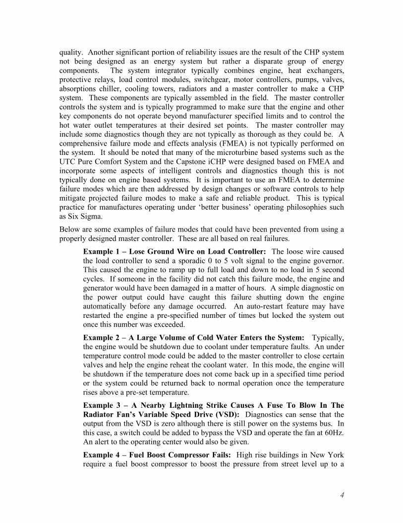
quality. Another significant portion of reliability issues are the result of the CHP system not being designed as an energy system but rather a disparate group of energy components. The system integrator typically combines engine, heat exchangers, protective relays, load control modules, switchgear, motor controllers, pumps, valves, absorptions chiller, cooling towers, radiators and a master controller to make a CHP system. These components are typically assembled in the field. The master controller controls the system and is typically programmed to make sure that the engine and other key components do not operate beyond manufacturer specified limits and to control the hot water outlet temperatures at their desired set points. The master controller may include some diagnostics though they are not typically as thorough as they could be. A comprehensive failure mode and effects analysis (FMEA) is not typically performed on the system. It should be noted that many of the microturbine based systems such as the UTC Pure Comfort System and the Capstone iCHP were designed based on FMEA and incorporate some aspects of intelligent controls and diagnostics though this is not typically done on engine based systems. It is important to use an FMEA to determine failure modes which are then addressed by design changes or software controls to help mitigate projected failure modes to make a safe and reliable product. This is typical practice for manufactures operating under ‘better business’ operating philosophies such as Six Sigma. Below are some examples of failure modes that could have been prevented from using a properly designed master controller. These are all based on real failures.
Example 1 – Lose Ground Wire on Load Controller: The loose wire caused the load controller to send a sporadic 0 to 5 volt signal to the engine governor. This caused the engine to ramp up to full load and down to no load in 5 second cycles. If someone in the facility did not catch this failure mode, the engine and generator would have been damaged in a matter of hours. A simple diagnostic on the power output could have caught this failure shutting down the engine automatically before any damage occurred. An auto-restart feature may have restarted the engine a pre-specified number of times but locked the system out once this number was exceeded.
Example 2 – A Large Volume of Cold Water Enters the System: Typically, the engine would be shutdown due to coolant under temperature faults. An under temperature control mode could be added to the master controller to close certain valves and help the engine reheat the coolant water. In this mode, the engine will be shutdown if the temperature does not come back up in a specified time period or the system could be returned back to normal operation once the temperature rises above a pre-set temperature. Example 3 – A Nearby Lightning Strike Causes A Fuse To Blow In The Radiator Fan’s Variable Speed Drive (VSD): Diagnostics can sense that the output from the VSD is zero although there is still power on the systems bus. In this case, a switch could be added to bypass the VSD and operate the fan at 60Hz. An alert to the operating center would also be given.
Example 4 – Fuel Boost Compressor Fails: High rise buildings in New York require a fuel boost compressor to boost the pressure from street level up to a
4
pressure required by the engine. Diagnostics can be added to detect if the compressor has failed and switch on the backup compressor.
2. General System Description The CHP system design for Utica College consists of four engine generator sets, each with their own set of system modules. Each generator set will contain a engine/generator/engine controls module, jacket water heat recovery system module, system controls module, auxiliary water module, and an exhaust heat recovery system module. The purpose of the CHP installation is to recover heat from the engine to offset energy consumption for building heating, domestic hot water and firing of an absorption chiller for cooling.
The advantages of increased modularization and standardization are lower engineering and installation costs, higher footprint flexibility; lower components costs through procuring larger quantities of the same parts, and higher reliability through the use of components with known operating histories. Improved stability and controllability would help decrease the need for operator involvement in the operation of CHP installations. This section briefly describes the function of major CHP components and sub-systems.
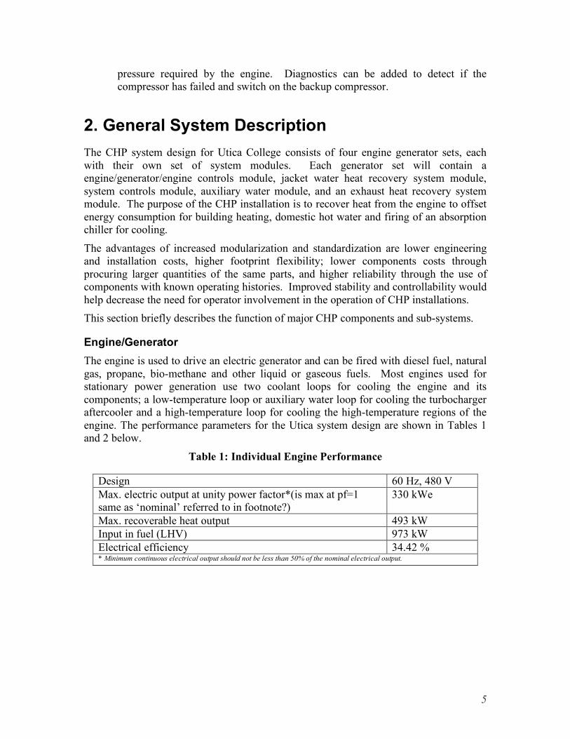
Engine/Generator The engine is used to drive an electric generator and can be fired with diesel fuel, natural gas, propane, bio-methane and other liquid or gaseous fuels. Most engines used for stationary power generation use two coolant loops for cooling the engine and its components; a low-temperature loop or auxiliary water loop for cooling the turbocharger aftercooler and a high-temperature loop for cooling the high-temperature regions of the engine. The performance parameters for the Utica system design are shown in Tables 1 and 2 below.
Table 1: Individual Engine Performance
Design 60 Hz, 480 V Max. electric output at unity power factor*(is max at pf=1 same as ‘nominal’ referred to in footnote?)
330 kWe
Max. recoverable heat output 493 kW Input in fuel (LHV) 973 kW Electrical efficiency 34.42 % * Minimum continuous electrical output should not be less than 50% of the nominal electrical output.
5

Table 2: Overall System Performance with Four Engines
Design 60 Hz, 480 V Max. electric output at unity power factor 1320 kWe Max. heat output (HT water circuit & exhaust gas) 1972 kW Input in fuel (LHV) 3892 kW Electrical efficiency 34.42 % * Minimum continuous electrical output should not be less than 50% of the nominal electrical output.
Engine Controller The engine controller will typically be supplied by the engine manufacture and will be used to control ignition, air/fuel ratio, speed, emissions, and detonation. The engine controller will also monitor other parameters, such as oil temperature and coolant temperatures; will shut down the engine to protect it, as required; will give permission for starting; and will control the generator voltage.
Master Controller/System Controls The system controller will control the CHP system, engine start and stop, loading, and paralleling switchgear. The engine controls are typically separate from the master controller, although both controllers will communicate with each other.
Jacket Water Module The jacket water module consists of an engine driven jacket water pump and a jacket water heat exchanger (see “JW Pump” and “JW HX” on Figure 1) that transfers heat to the high temperature water circuit and/or to the Intermediate heat exchanger, depending upon the operation of Valve 10.
High Temperature Water Module The high temperature water module (Figure 1) includes a water pump, exhaust heat exchanger, 3-way valves V10 and V11, and an intermediate heat exchanger. GTI found that most CHP installations in the U.S. use exhaust diverter valves. A decision was made to not use exhaust diverter valves due to their high cost, poor reliability, and problems associated with leakage. As a result, the cooling tower radiators should be sized to handle the full thermal output of all four engines (exhaust and jacket water heat recovery). One deviation from Figure 1 for this installation is that the cooling tower will serve all four engines. The purpose of valve V11 is to control the flow to the chiller or boiler depending on the mode of operation and permissives from the associated equipment. Valve V10 is used to control the output temperature T13. V10 will always have to be opened a minimum amount to prevent flashing in the exhaust heat exchanger. Some chillers may require a high enough temperature at T13 such that the full water jacket flow would be too high to achieve the desired temperature. For those cases, V10 will operate to divert a part of the flow leaving the jacket water heat exchanger directly to the intermediate heat exchanger, thus reducing the flow to the exhaust heat exchanger and increasing the temperature at
6
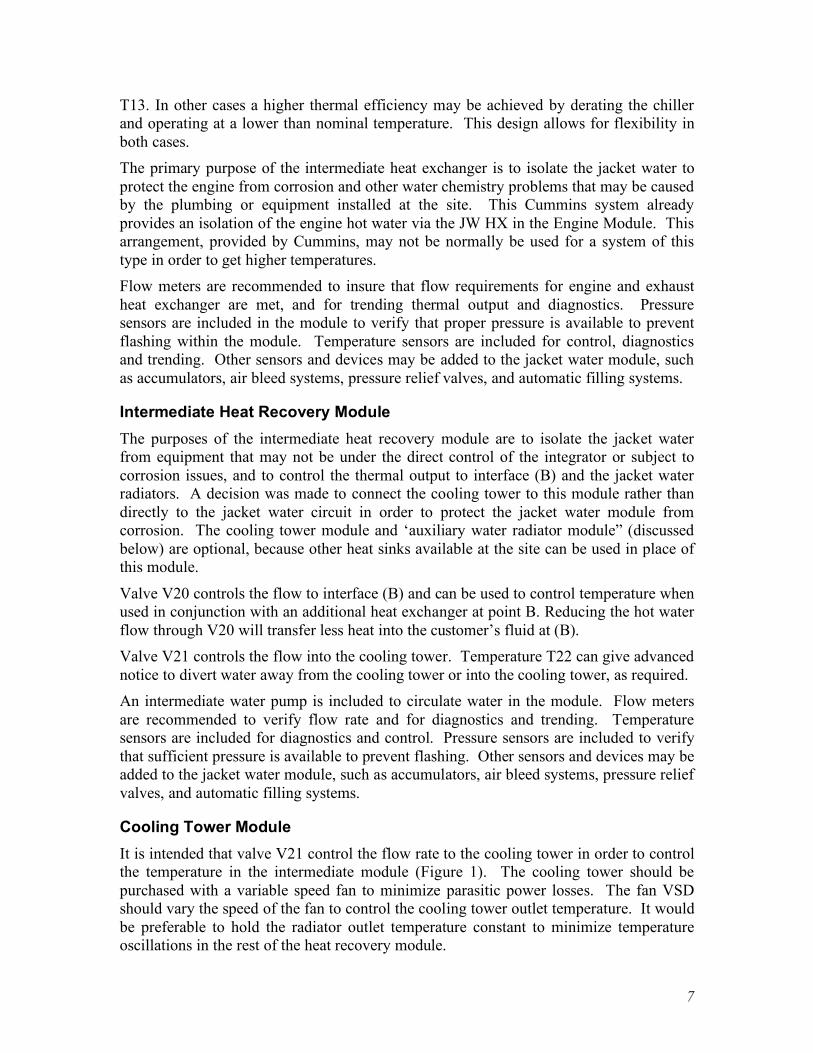
T13. In other cases a higher thermal efficiency may be achieved by derating the chiller and operating at a lower than nominal temperature. This design allows for flexibility in both cases. The primary purpose of the intermediate heat exchanger is to isolate the jacket water to protect the engine from corrosion and other water chemistry problems that may be caused by the plumbing or equipment installed at the site. This Cummins system already provides an isolation of the engine hot water via the JW HX in the Engine Module. This arrangement, provided by Cummins, may not be normally be used for a system of this type in order to get higher temperatures. Flow meters are recommended to insure that flow requirements for engine and exhaust heat exchanger are met, and for trending thermal output and diagnostics. Pressure sensors are included in the module to verify that proper pressure is available to prevent flashing within the module. Temperature sensors are included for control, diagnostics and trending. Other sensors and devices may be added to the jacket water module, such as accumulators, air bleed systems, pressure relief valves, and automatic filling systems.
Intermediate Heat Recovery Module The purposes of the intermediate heat recovery module are to isolate the jacket water from equipment that may not be under the direct control of the integrator or subject to corrosion issues, and to control the thermal output to interface (B) and the jacket water radiators. A decision was made to connect the cooling tower to this module rather than directly to the jacket water circuit in order to protect the jacket water module from corrosion. The cooling tower module and ‘auxiliary water radiator module” (discussed below) are optional, because other heat sinks available at the site can be used in place of this module.
Valve V20 controls the flow to interface (B) and can be used to control temperature when used in conjunction with an additional heat exchanger at point B. Reducing the hot water flow through V20 will transfer less heat into the customer’s fluid at (B). Valve V21 controls the flow into the cooling tower. Temperature T22 can give advanced notice to divert water away from the cooling tower or into the cooling tower, as required. An intermediate water pump is included to circulate water in the module. Flow meters are recommended to verify flow rate and for diagnostics and trending. Temperature sensors are included for diagnostics and control. Pressure sensors are included to verify that sufficient pressure is available to prevent flashing. Other sensors and devices may be added to the jacket water module, such as accumulators, air bleed systems, pressure relief valves, and automatic filling systems.
Cooling Tower Module It is intended that valve V21 control the flow rate to the cooling tower in order to control the temperature in the intermediate module (Figure 1). The cooling tower should be purchased with a variable speed fan to minimize parasitic power losses. The fan VSD should vary the speed of the fan to control the cooling tower outlet temperature. It would be preferable to hold the radiator outlet temperature constant to minimize temperature oscillations in the rest of the heat recovery module.
7

Auxiliary Water Module The purpose of this module is to cool the low-temperature coolant loop of the engine. Coolant in this module will be circulated by an engine-driven pump to a dump radiator. The radiator may be combined with one or more engines. With smaller engines, it is not worth the extra cost to recover heat from this module, although it may be beneficial if efficiency credits are a factor in the project. For this installation the module consists of a flow meter, control valve V1 and temperature sensors. A flow meter is recommended to verify that the engine flow requirements are met and for trending and diagnostics. Valve V1 is used to control the flow to the radiators, and temperature sensors are used to control V1 and for diagnostics and trending. Other sensors and devices may be added to the jacket water circuit, such as accumulators, air bleed systems, pressure relief valves, and automatic filling systems.
Auxiliary Water Radiator Module Individual auxiliary radiators or one large radiator may be used to serve all four engines. It is recommended that the radiator be supplied with a variable speed fan. The radiator VSD should control the speed of the fans to control the radiator outlet temperature. It was envisioned that this module would include its own controls for the radiator outlet temperature.
8
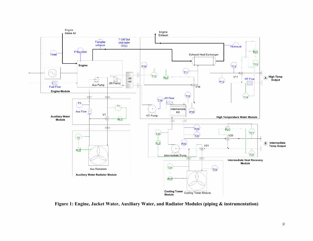
Figure 1: Engine, Jacket Water, Auxiliary Water, and Radiator Modules (piping & instrumentation)
9

3. Major Equipment The Combined Heat and Power Unit (CHP unit) comprises the generator set (engine, alternator & control panel) and heat recovery system (HT cooling module & additional controls) housed within an acoustically treated enclosure. Included within the standard module is a suitably rated, 3-pole, electrically operated insulated case circuit breaker. A suitably sized gas train is supplied mounted inside the enclosure.
The standard unit is arranged for 480 volts , 60Hz electrical generation, parallel operation with the grid, 195ºF hot water outlet temperature and an exhaust NOx emission limit of maximum 0.5 g/bhp-hr. The complete System will incorporate all major equipment necessary for the safe, efficient and reliable operation of a cogeneration system.
Four (4) new natural gas-fired Cummins QSK19G lean-burn reciprocating engine-generator sets, rated 2055 kWe @ 1800 rpm, 3-phase, 60 Hz, maximum NOx emissions of 2 g /BHP-hr
Four (4) 4160v/480v transformers Synchronizing switchgear necessary to synchronize with Con Edison through the power
converters Protective relays required as per Con Edison interconnect standards Breakers required to isolate and operate the System during a Con Edison electric outage Gas booster pump(s) as necessary to supply natural gas to the System Four exhaust heat recovery hot water heat exchangers capable of producing and delivering
high-temperature water to the existing hot water system Cooling tower(s) and/or dump radiator(s) as necessary to cool the System Heat exchangers Temperature sensors Pressure sensors Flow meters Temperature control valves Motor control center Sound damping material and baffles to sound attenuate the System’s room Motorized intake and exhaust louvers, as well as ventilation ducting and fans Distribution panel(s) for auxiliary power for the System PLC (programmable logic control) based control system for the interface, signaling and
operation of the Facility’s valves and other equipment. The PLCs provide the signals that trigger specific equipment, such as the opening and closing of valves or radiator on/off.
Monitoring and communications system for both local [Facility’s Building Management System (BMS)] and remote (Contractor and Company) data transmittal and report generation.
Environmental enclosure to protect the equipment from the elements and to contain spills.
10
4. System Location and Enclosure An insulated, sound-attenuated cogeneration enclosure will be set on structural steel dunnage tied to the ground The System enclosure will contain the engine-generator sets, exhaust heat recovery units, exhaust silencers, waste and auxiliary heat exchangers, switchgear, control system, expansion tanks and other ancillary equipment and support systems. The System enclosure will be approximately 50 ft. by 50 ft. with a maximum height of 34 ft. (including all engine and enclosure intake and exhaust equipment). A new cooling tower will also be installed to serve the System. The cooling tower will include the best commercial-available plume abatement technology. The cooling tower will be located on the structural steel dunnage, adjacent to the cogeneration enclosure and will have an approximate footprint of 9 ft. by 21 ft. with a maximum height of 14 ft. The system location will provide access for fully servicing the equipment including major overhauls and replacements such as generator replacements. The layout should include easy access for common maintenance items such as oil changes and filter replacements.
4.1 Combustion and Cooling Air
Heat radiated from the engine, alternator, heat exchangers and pipe work within the enclosure will be removed by a fan induced cooling airflow which enters the unit through mechanically operated louvers in the CHP module. Cooling air is discharged through ventilation grilles in the enclosure, at the non-drive end of the engine. The electric fan is installed inside the enclosure. To ensure that the aspiration air does not exceed the allowed limit and avoid derating of the engine, aspiration air will be ducted to the filter from louvers in the side of the enclosure.
Radiated heat 63.3 kW
Aspiration air 990 scfm
Cooling airflow through the enclosure, excluding aspiration air
13,200 ft3/min
Maximum temperature of inlet air 105 F * Radiated heat is the heat radiated to ambient from the engine, alternator and heat recovery equipment located within the enclosure. Cooling airflow is calculated on the basis of a 15°F pick-up through the enclosure at a 105°F ambient. For lower ambient temperatures then, provided that the discharge temperature from the enclosure does not exceed 120°F, a lower cooling airflow would be acceptable
4.2 Environmental
The enclosure should provide NEMA 4 protection to the equipment inside of the enclosure. The enclosure should contain liquid spills up to the largest possible spill from a single system inside the enclosure containing liquid and should have the appropriate means to drain such a spill.
11
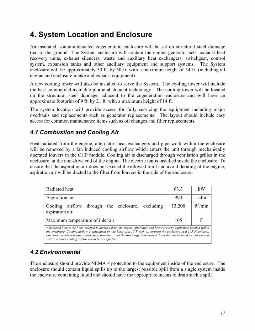
4.3 Exhaust Gas Discharge
Exhaust gases are to be discharged outside the enclosure either via an exhaust silencer or directly from the exhaust gas discharge flanges on the enclosure. The exhaust pipework must have a downward gradient from the connection point on the enclosure. At the lowest point of the exhaust pipe a condensate drain must be incorporated. The exhaust system within the enclosure will be suitably insulated to prevent heat loss within the enclosure. All site installed exhaust system components external to the enclosure should be suitably insulated and clad as part of the installation process. All exhaust ducting will be made of stainless steel to prevent corrosion.
Mass flow of exhaust gases 4,700 lb/hr
Temperature of exhaust gases @ rated load 985 F
Maximum allowable back pressure on the engine 15 inches WG
4.4 Noise Emissions
The enclosure is designed to achieve an external noise level of 80dB(A) at 1 meter external to the enclosure under free-field, non-reverberant conditions.
4.5 Paint and Finish
The equipment will be finished in an oil resistant, high gloss enamel, CPG green, shade Munsell #1.5BG4.38/6.5 or equivalent.
4.6 Dimensions and Weights
The engine module weights and dimensions are shown below.
Length 15.0 ft
Width 30 ft
Height 8.0 ft
CHP module transport weight 18,000 lbs
Operating (wet) weight 20,000 lbs
5. Engine The Cummins QSK19G is a heavy duty, spark ignited engine based on the proven reliability and durability of the Cummins Q19-series diesel platform. The QSK19G engine features a state-of-the-art electronic ignition system for improved fuel consumption, high reliability, and low emissions. The standard engine includes oil filtration, air inlet filters suitable for normal operating conditions and electric starting.
12
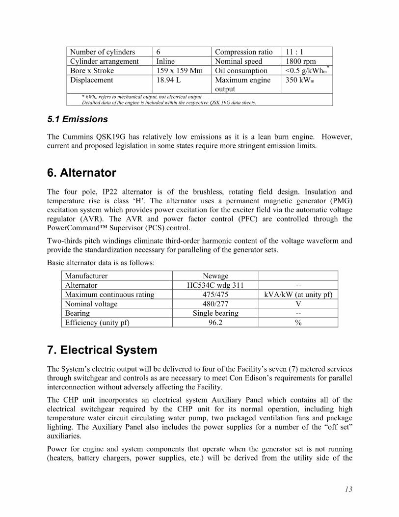
Number of cylinders 6 Compression ratio 11 : 1 Cylinder arrangement Inline Nominal speed 1800 rpm Bore x Stroke 159 x 159 Mm Oil consumption <0.5 g/kWhm
*
Displacement 18.94 L Maximum engine output
350 kWm
* kWhm refers to mechanical output, not electrical output Detailed data of the engine is included within the respective QSK 19G data sheets.
5.1 Emissions
The Cummins QSK19G has relatively low emissions as it is a lean burn engine. However, current and proposed legislation in some states require more stringent emission limits.
6. Alternator The four pole, IP22 alternator is of the brushless, rotating field design. Insulation and temperature rise is class ‘H’. The alternator uses a permanent magnetic generator (PMG) excitation system which provides power excitation for the exciter field via the automatic voltage regulator (AVR). The AVR and power factor control (PFC) are controlled through the PowerCommand™ Supervisor (PCS) control.
Two-thirds pitch windings eliminate third-order harmonic content of the voltage waveform and provide the standardization necessary for paralleling of the generator sets.
Basic alternator data is as follows:
Manufacturer Newage Alternator HC534C wdg 311 --Maximum continuous rating 475/475 kVA/kW (at unity pf) Nominal voltage 480/277 V Bearing Single bearing --Efficiency (unity pf) 96.2 %
7. Electrical System The System’s electric output will be delivered to four of the Facility’s seven (7) metered services through switchgear and controls as are necessary to meet Con Edison’s requirements for parallel interconnection without adversely affecting the Facility. The CHP unit incorporates an electrical system Auxiliary Panel which contains all of the electrical switchgear required by the CHP unit for its normal operation, including high temperature water circuit circulating water pump, two packaged ventilation fans and package lighting. The Auxiliary Panel also includes the power supplies for a number of the “off set” auxiliaries.
Power for engine and system components that operate when the generator set is not running (heaters, battery chargers, power supplies, etc.) will be derived from the utility side of the
13

mounted paralleling circuit breaker (CB) through a suitably sized CB. All genset and CHP module ancillary equipment will be connected within a single distribution panelboard. (Module installation will require no additional power circuit from the facility.) Electrical output from the generator set will be via a suitably rated, 3-pole, 5 cycle closing, electrically operated circuit breaker. This circuit breaker will be fixed mounted in its own enclosure within the module enclosure with clear accessibility for manual breaker operation through a door in the enclosure. The CB design most likely will not withstand Genset vibrations and so must be mounted to the Genset housing or the module’s bedframe. Connections between the alternator’s output bus and the CB will be with suitably sized flexible cables and supported as required to withstand vibration movement. A neutral bar, minimum size full load current (502 amps) will be included in the CB enclosure beside the CB and similarly connected to the alternator neutral bus.
The CB and neutral bus outputs will have mechanical lugs suitable for the amperage rating of the Genset. Spacing for connections and bending of load cables will be for 125% oversized, 75°C cables, minimum 2 cables per phase in accordance with the U.S. National Electrical Code. Power cables will enter the CB enclosure through the bottom and will enter the Genset housing through the bottom. The CB enclosure bottom will have a removable gland plate to ease installation of customer conduits and cables.
The System will be designed to operate at optimal output during the on-peak hours of the Con Edison electric system and will include electric load following controls that will modulate the System’s electric output to maintain Con Edison’s minimum import requirements. Conduits will provide EMF (electro-magnetic flux) shielding except for those portions of conduit which are located in areas which are more than ten (10) feet away from any electronic equipment, office space, retail space or other occupied space or high-traffic area.
The System will include two (2) five thousand (5,000) amp switches to deliver backup power service to the Facility in the event of a Con Edison power outage. One such switch will be connected to a new 4160v/480v transformer and then to a new backup power panel, installed as part of the System, which will include two (2) eight hundred (800) amp switches, six (6) four hundred (400) amp switches and space to install one (1) additional eight hundred (800) amp switch or two (2) additional four hundred (400) amp switches. The System will be designed to automatically disconnect from the Facility’s electrical distribution system and provide power to each of the two new five thousand (5,000) amp switches within fifteen (15) minutes of a Con Edison power outage. It is understood that the operation of the System during a Con Edison power outage is predicated on the continued flow of natural gas to the System from Con Edison’s gas system and a minimum connected load of 1,000 kW. The contractor will provide a complete relay protection package to protect all equipment installed and to ensure proper coordination with the utility and plant power distribution systems. The contractor will provide complete three-line and schematic diagrams depicting all relays, controls, circuit numbers, terminal numbers, wire designations, test devices, and other equipment required to completely represent the protection schemes being utilized. The plant will provide, but not be limited to, the following interconnection protection:
14
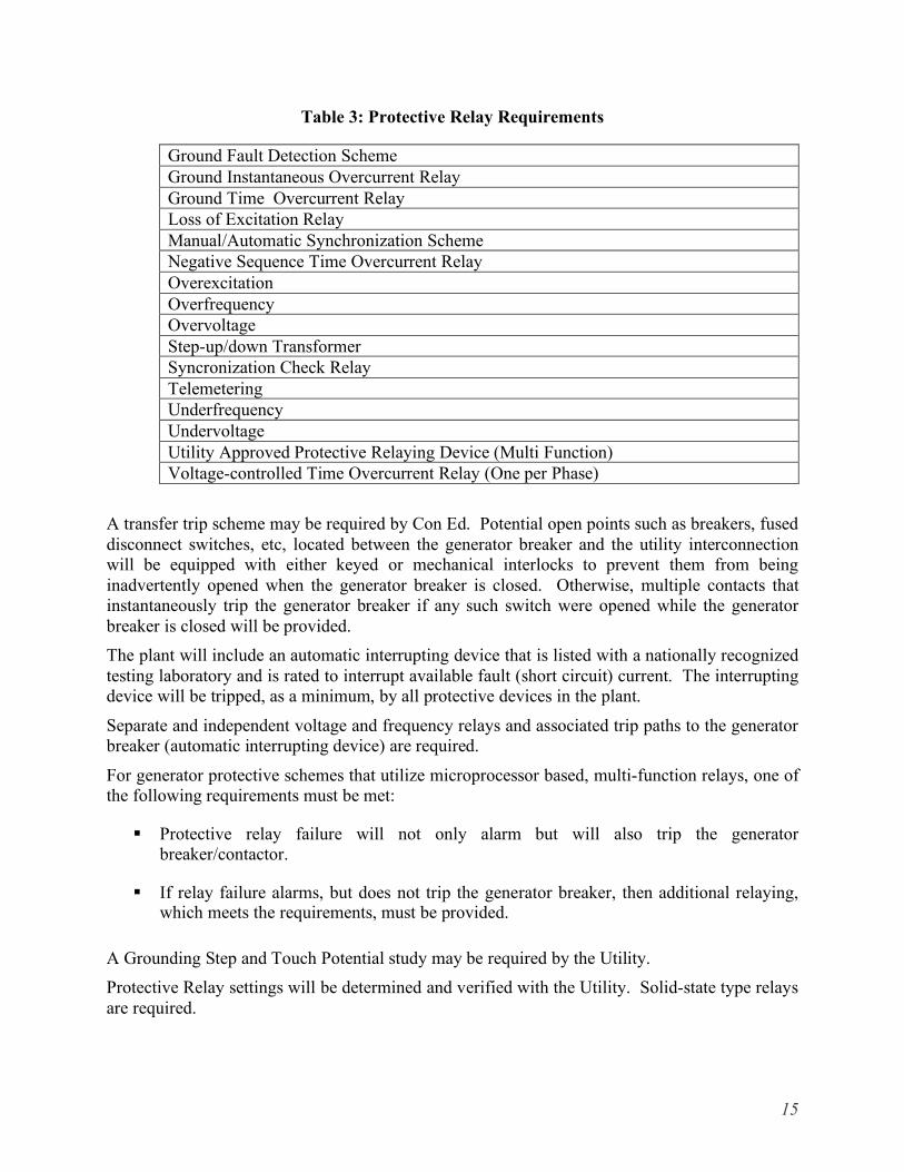
Table 3: Protective Relay Requirements
Ground Fault Detection Scheme Ground Instantaneous Overcurrent Relay Ground Time Overcurrent Relay Loss of Excitation Relay Manual/Automatic Synchronization Scheme Negative Sequence Time Overcurrent Relay Overexcitation Overfrequency Overvoltage Step-up/down Transformer Syncronization Check Relay Telemetering Underfrequency Undervoltage Utility Approved Protective Relaying Device (Multi Function) Voltage-controlled Time Overcurrent Relay (One per Phase)
A transfer trip scheme may be required by Con Ed. Potential open points such as breakers, fused disconnect switches, etc, located between the generator breaker and the utility interconnection will be equipped with either keyed or mechanical interlocks to prevent them from being inadvertently opened when the generator breaker is closed. Otherwise, multiple contacts that instantaneously trip the generator breaker if any such switch were opened while the generator breaker is closed will be provided. The plant will include an automatic interrupting device that is listed with a nationally recognized testing laboratory and is rated to interrupt available fault (short circuit) current. The interrupting device will be tripped, as a minimum, by all protective devices in the plant.
Separate and independent voltage and frequency relays and associated trip paths to the generator breaker (automatic interrupting device) are required.
For generator protective schemes that utilize microprocessor based, multi-function relays, one of the following requirements must be met:
Protective relay failure will not only alarm but will also trip the generator breaker/contactor.
If relay failure alarms, but does not trip the generator breaker, then additional relaying, which meets the requirements, must be provided.
A Grounding Step and Touch Potential study may be required by the Utility. Protective Relay settings will be determined and verified with the Utility. Solid-state type relays are required.
15
The DC system will provide power to all relay protection schemes and to trip circuits of all switchgear.
Circuit breaker trip circuits will be monitored with both the open and closed positions and alarm if the trip circuit opens or the power fails. Lockout relay coils will be monitored in a like manner.
8. Heat Recovery System From the view of recovering waste heat the CHP unit consists of three independent circuits, HT water module (from engine jacket), LT auxiliary water module and exhaust gas module (which is not part of the design of this project) . The CHP module will only recover heat from the HT circuit. LT heat recovery, if any, is not part of the project design. In addition, no exhaust heat recovery is included in the Cummins package but the heat is utilized in the HT water module as shown in Figure 1.
The jacket water circuit from the Cummins supplied package is routed through the Jacket Water (JW) heat exchanger and is circulated by an engine driven pump. The supply and return of the process water side of this heat exchanger will be provided with two flanged connections at the external edge of the housing. The flanges will be visibly marked supply and return.
The LT circuit supply and return from the Cummins supplied package is provided with two flanged connections at the external edge of the housing. The flanges will be visibly marked supply and return. This circuit would be dumped to the auxiliary water radiator module.
8.1 High Temperature Water Module
The high temperature module is described in the general system description. The complete high temperature heat recovery system (Figure 1) consists of the following items:
• Exhaust heat exchanger • Control valves V10 and V11 • Intermediate heat exchanger • Expansion vessel • Over pressure relief valve • Fill and drain connections • Flexible bellows connections • Automatic de-aeration system • Water pressure sensors P10 and P12 • Water temperature sensors T10, T11, T12, T13, T14, T15, and T16 • Binder (connection) points
16

The expected thermal output from the heat generated during operation of the engine and collected from the engine block and oil cooler is as follows (note this is not the entire thermal output from the engine system):
Heat output (HT engine jacket water & oil cooler) 0.79 mmBTU/h
Maximum outlet temperature to the customer module 195 °F
8.2 Auxiliary Water Module
The auxiliary water cooling module is described in the general system description. This is the cooling module which removes heat from the charge air cooler during operation of the engine. Water is circulated via the engine driven mechanical pump. The expected thermal output from the auxiliary circuit is shown below.
Heat output, LT cooling module 0.24 mmBTU/h
Nominal temperature of water, engine outlet 122 °F
Maximum temperature of water, engine inlet 104 °F
Water flow 26 Gal/hr
Maximum external restriction 7 psi
The complete Auxiliary Water cooling module will consist of the following items. • Aux radiators • Control valve V1 • Temperature Sensors T1, T2 and T3
8.3 Exhaust Gas Module
The exhaust is terminated from the Cummins CHP module with a stainless steel ANSI flange termination at the edge of the housing, for optional heat recovery, SCR or silencer applications. An internal flexible stainless steel section will be between the engine and the flange connection. This is not detailed in the Figure 1 drawing as the design was the completed given the cancellation of the actual installation. The exhaust heat recovery heat exchanger and the remaining exhaust ducting should be constructed from stainless steel.
Nominal temperature of exhaust gas, turbocharger outlet at rated load 530 °C
Exhaust gas flow rate at full load 4,700 Lb/h
17
9. Engine Controls/Master Controller Requirements 9.1 Control and Monitoring System
The System’s control system will be integrated (electrically and thermally) so as to allow for autonomous operation not requiring site intervention or actions for normal operation in grid-parallel mode and will interface with the Facility’s controls to ensure efficient and reliable operation. The System’s control system will be designed to interface with the Facility’s building management system and the internet for the purposes of monitoring, issuing alarm notification and accessing the System’s control system remotely.
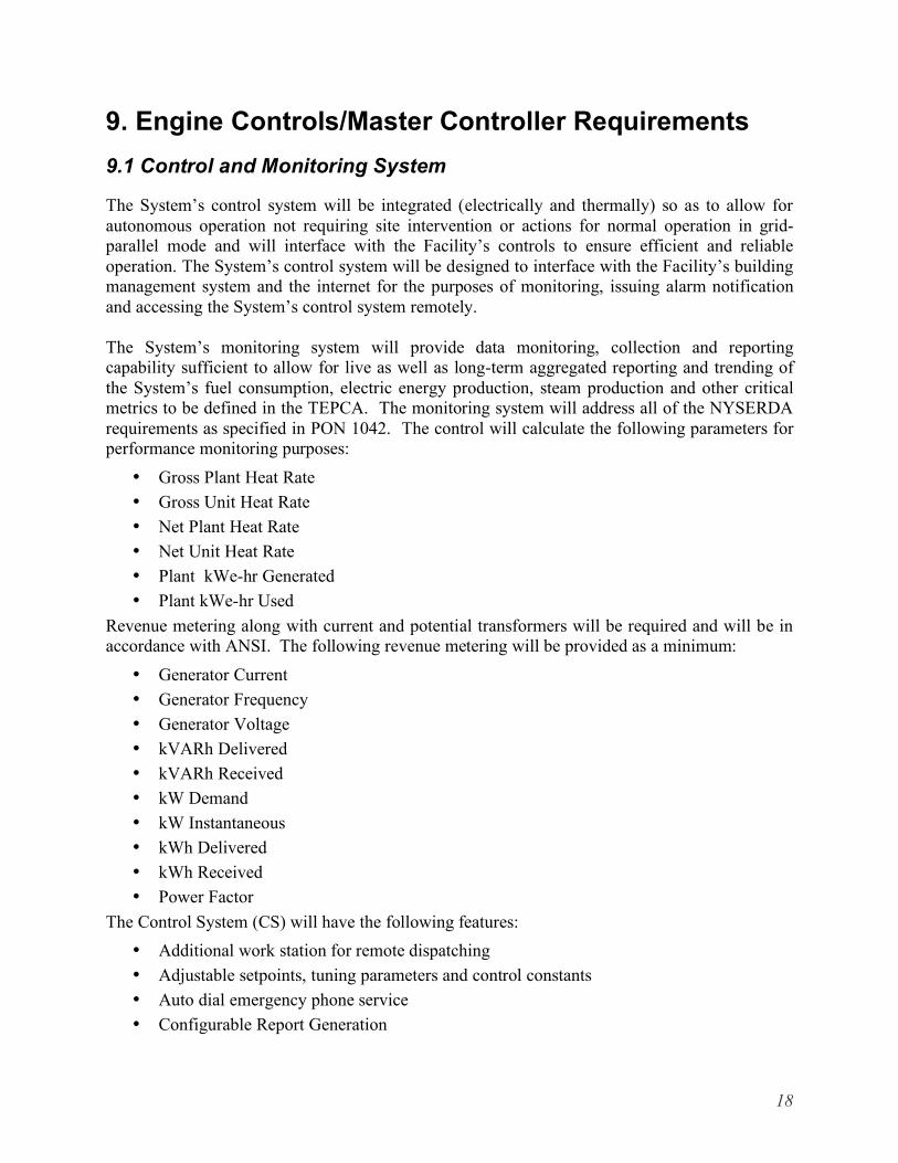
The System’s monitoring system will provide data monitoring, collection and reporting capability sufficient to allow for live as well as long-term aggregated reporting and trending of the System’s fuel consumption, electric energy production, steam production and other critical metrics to be defined in the TEPCA. The monitoring system will address all of the NYSERDA requirements as specified in PON 1042. The control will calculate the following parameters for performance monitoring purposes:
• Gross Plant Heat Rate • Gross Unit Heat Rate • Net Plant Heat Rate • Net Unit Heat Rate • Plant kWe-hr Generated • Plant kWe-hr Used
Revenue metering along with current and potential transformers will be required and will be in accordance with ANSI. The following revenue metering will be provided as a minimum:
• Generator Current • Generator Frequency • Generator Voltage • kVARh Delivered • kVARh Received • kW Demand • kW Instantaneous • kWh Delivered • kWh Received • Power Factor
The Control System (CS) will have the following features: • Additional work station for remote dispatching • Adjustable setpoints, tuning parameters and control constants • Auto dial emergency phone service • Configurable Report Generation
18

• Continuous Emissions Monitoring integrated in Central Control System • Control functions separated from protection/shutdown functions • Diagnostic Trending • Dynamic graphic displays • Historical data retrieval • Integration of all control systems into Central Control System • Multiple priority level alarm management • Multiple security levels with password protection (System Security Levels) • Printer logging • Redundant data highway • Redundant power supplies • Redundant processors • Remote Dispatching Capability • Remote I/O implementation if applicable • Self-diagnostics accessible from work stations • Sequence of events recording at 1ms resolution
The historical data retrieval (or real time access) should be accessible by third party software via open protocols such as SQL or OPC. Appropriate sensors (i.e. pressure and temp) should used to ensure that boiling only occurs where it is supposed to. The system should include provisions for automatic bypass on any variable speed drives used for pumps or fans (so system can still operate if they fail) and should include surge protectors on power supplies.
For control of the CHP unit, a control system will be included which will operate all necessary equipment for the HT water circuit, circulating water pump(s), battery charger and ventilation fan(s), etc. Also incorporated within the control system is a remote monitoring system. This interconnects with the generator control system and includes facilities for:
• Ethernet point for local connection of a laptop PC
• RS485 Modbus communication port.
• Access from a remote location via a telephone or DSL line.
For purposes of paralleling operation the electrically operated output circuit breaker will be controlled by the PowerCommand™ Supervisor (PCS) Paralleling control.
The controller should have the capability for interfacing with OPC servers for easy integration into the Intelligent OperatorTM .
19
9.2 Operational States
The control system design consists of several states or operating modes depending on the condition and status of the CHP system.
Start State In the startup state, the system controller will perform diagnostic checks, such as to verify valve movement with either valve position feedback or using a limit switch to verify that the valves can be fully stroked. The temperature sensor values will also be checked to verify that they are within appropriate ranges. Many temperature transmitters have fault-signal outputs to report faults, such as open circuits, shorts, or readings out of expected ranges. Faults can be read from the transmitter, or control software can be written for fault detection within the master controller.
Once the diagnostic checks are completed and passed, the water flow control valves should be returned to their start up positions, and the controller will issue a start command to the engine. Valves V1, V10 and V21 should be in full bypass position to prevent flow to the radiators or customer loads during startup. Valve V10 should be fully open to allow the full jacket water flow to go to the exhaust heat exchanger. When the engine reaches full speed, the synchronizer will synchronize the engine to the grid and close the generator circuit-breaker. The engine will then ramp up to the power demanded by the load control.
Thermal Warm-Up State This state controls the thermal circuits while the engine and coolant loops warm up. The controller will monitor T1 and T10 in separate control loops. Once T1 and T10 reach their required temperatures, the auxiliary water and jacket water coolant circuits will be controlled by their own respective controllers. During thermal warm up, T1 will be monitored. Once T1 reaches its warm-up state set point temperature (T1warm), the control for the auxiliary water circuit will switch to the “auxiliary water control Loop”
T10 will be monitored for the jacket water circuit. Once T10 reaches its warm-up state set point (T10warm), the control for the jacket water circuit will switch to the jacket water control loop.
If one of the circuits does not reach its warm-up state set point within an allotted period of time, control should be transferred to the appropriate under-temperature states described later.
Auxiliary Water Control In this control scheme, the controls will attempt to maintain a constant outlet temperature from the auxiliary water radiators by adjusting the fan speeds or varying the number of fans turned on. The assumption is that this scheme will help to stabilize the auxiliary water loop temperature. Feedback from T1 will be used to adjust the position of valve V1. With some engines, control of the auxiliary water temperature is much more critical than others. If tight control of the auxiliary water is critical, the follow precautions are recommended:
• If the T1 drops below its lower limit once the system has entered the auxiliary water control loop state, the control should be transferred to the auxiliary water under-temperature state.
20

• Conversely, if T1 increases above its upper temperature limit, control should be transferred to the auxiliary water over-temperature state.
Jacket Water Control Similar to the auxiliary water control, the jacket water controls will attempt to maintain a constant outlet temperature (T24) from the cooling tower by adjusting the fan speeds or varying the number of fans turned on. This scheme is thought to help stabilize the water jacket loop temperature, thereby allowing for increased thermal output. The return temperature back to the engine will ultimately be controlled by V21.
Interface (A) was included for situations where the outlet temperature needs to be as high as possible such as for use with an absorption chiller. V10 serves to control the temperature at interface (A) when the required temperature is higher than it would be if the full flow were sent to the exhaust heat exchanger.
V11 controls the flow rate to high temperature outlet at interface (A). When the thermal load is first activated, care should be taken to prevent under-temperature faults. When thermal output is first requested from this interface, V11 will first be opened to a minimum setting such as 10%. Once the return temperature T14 is above an acceptable temperature, V11 can be opened further.
V20 controls the flow to the intermediate temperature output at interface (B). As mentioned before, V20 will not control temperature unless it is used in conjunction with another heat exchanger. V21 controls the flow into the cooling tower and the mixed out temperature T25 going to the intermediate heat exchanger, which in turn controls T16 going back to the engine.
If T10 should drop below its under-temperature limit or rise above its over-temperature limit, control should be transferred to the appropriate under-temperature or over-temperature recovery state.
Heat Distribution Control Before finalizing the site installation design, the installer should establish priorities for thermal loads. System optimization controls described below can also be used to establish thermal load priorities. Once priorities are set, the heat distribution control will then dispatch the various thermal loads, based on priority, temperatures required and heat available. If an absorption chiller is included in the package, the chiller will normally take priority when the package is in cooling mode. The heat distribution controls should also monitor return temperature and close valves as required to prevent under-cooling.
9.3 Recovery States
Under-Temperature and Over-Temperature States Normally, the control schemes described above should be able to control the CHP equipment. Should an event occur that causes a large perturbation to the system, additional controls may be required to stabilize the system. One such perturbation could be caused by someone opening a valve in the building that sends a slug of cold water to the CHP equipment on a cold winter day. The slug of cold water could ultimately cause the jacket water to be over-cooled and result in an under-temperature fault on the engine. The primary objective of these controls is to keep the engine running so the operator does not incur demand charges.
21
Water Jacket Over-Temperature State If T10 exceeds its first over-temperature limit, an over-temperature timer is started, valve V21 is opened to its 100% position, and the cooling tower fans are set to maximum heat rejection. If T14 or T22 detect that customer return water temperature is higher than the outlet temperatures T13 or T21, control valves V11 or V20 should be closed as appropriate, although this latter situation should not normally occur. If T10 drops below the first over-temperature limit, control can be switched back to the normal jacket water control. If the over-temperature timer exceeds its first time limit, then the engine output will be reduced by 50%. If the over-temperature timer exceeds its second time limit, an over-temperature fault will be issued and the engine will be shut down.
Water Jacket Under-Temperature State If T10 drops below its first under-temperature limit, an under-temperature timer is started. T14, T22 or T24 should be used to detect the source of the under-temperature. If the source is determined to be T14 or T22, V11 or V20 should be closed to a minimum setting to reduce the propagation of the cold water into the system while at the same time heat up the cold water source.
If the source is determined to be the cooling tower, depending on the ambient temperature at the cooling tower, Valve V21 should be set to some minimum flow position. For example, if the ambient temperature is significantly below the T10 set point, V21 should be closed. (At this point the cooling tower fans should have already shutoff.) A T10 under-temperature event won’t likely occur unless T24 is below its set point.) If the under-temperature timer exceeds its first time limit, then control valves V11, V20 and V21 should be closed. If the under-temperature timer exceeds its second time limit then an under-temperature fault will be issued and the engine will be shut down.
Auxiliary Water Over-Temperature State When T1 exceeds its first over-temperature limit, an over-temperature timer is started and valve V1 is open to 100% position. In addition, the fan controller will set the fan speed to the highest setting or turn on the maximum number of fans at the aux radiators. If the over-temperature timer exceeds its first time limit, then the engine output will be reduced by 50%. If the over-temperature timer exceeds its second time limit then an over-temperature fault will be issued and the engine will be shut down.
Auxiliary Water Under-Temperature State Depending on the ambient temperature at the radiators or heat sink, Valve V1 should be set to some minimum flow position. For example, if the ambient temperature is significantly below the T1 set point, V1 should be closed. At this point the radiator fans should have already shutoff off since T1 under-temperature won’t occur unless T2 is below its set point. If the under-temperature timer exceeds its first time limit, then control valves V1 should be closed.
22

If the under-temperature timer exceeds its second time limit then an under-temperature fault will be issued and the engine will be shut down.
Customer Circuit Over-Temperature State No special state should be required. Valves V20 and the control valves on the heat distribution should be able to be closed to prevent overheating the customer circuit. However, faults should be created to take action, depending on the site’s requirements, when a customer’s temperature exceeds the normal setpoint tolerance band. If overheating could become a safety issue or cause equipment damage, the fault should shut down the CHP equipment. In other cases, a warning can be issued or no action taken.
Customer Circuit Under-Temperature State Since the CHP system already is protected, no special state should be required. It may be desirable to take action when a thermal demand is not met, such as issuing a warning or a signaling a boiler or heater to start, as designed.
9.4 Diagnostic Requirements
Additional diagnostic requirements will be required for the module containing the Intelligent Operator. These diagnostics will cover both engine and heat recovery diagnostics. Specific measurement points and purposes for each point are shown in Appendix A.
10. Supervisory Software Requirements 10.1 Purpose
The goal of the Intelligent OperatorTM (IO) is to improve reliability and reduce operating costs through an advanced control system and architecture. The IO compliments the improved CHP system design and master (or central) controller. Through continuous monitoring of the engine-generator set and CHP equipment, observations of small changes in equipment operation can identify degrading conditions before they result in major equipment downtime. Additionally, if adverse operating conditions can be detected early, changes can be made to the equipment to keep it running when problems occur. The advantage of the IO is that it can automatically detect changes in trends so that the operator does not have to be an expert in the CHP system and sort through large amounts of data. The IO will also incorporate optimization capabilities that will recommend scheduling for both the CHP plant and other equipment on site based on utility pricing.
10.2 Software Overview
The Intelligent Operator will collect data from other remote monitoring systems at the site and will have capability to collect data on its own if necessary. With regard to acquiring data from the existing data acquisition system, it is assumed that the data from the existing system can be acquired through an OPC server, a text file or SQL database. The data acquisition in the IO will be carried out by several different data acquisition models in the IO.
23
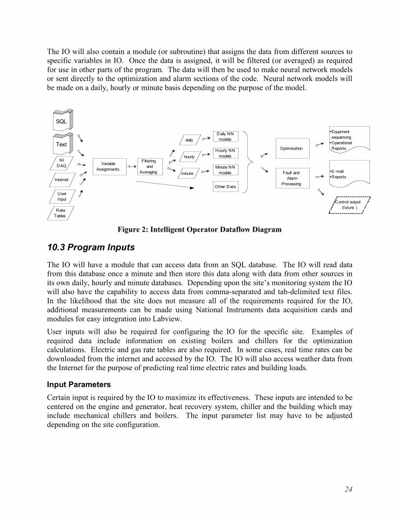
The IO will also contain a module (or subroutine) that assigns the data from different sources to specific variables in IO. Once the data is assigned, it will be filtered (or averaged) as required for use in other parts of the program. The data will then be used to make neural network models or sent directly to the optimization and alarm sections of the code. Neural network models will be made on a daily, hourly or minute basis depending on the purpose of the model.
NI
DAQ
User
Input
Internet
Rate
Tables
SQL
Text
Variable
Assignments
Filtering
and
Averaging
daily
hourly
minute
Daily NN
models
Minute NN
models
Hourly NN
models
Other Data
Optimization
Fault and
Alarm
Processing
•Equpment
sequencing
•Operational
Reports
•E -mail
•Reports
Control output
(future )
Figure 2: Intelligent Operator Dataflow Diagram
10.3 Program Inputs
The IO will have a module that can access data from an SQL database. The IO will read data from this database once a minute and then store this data along with data from other sources in its own daily, hourly and minute databases. Depending upon the site’s monitoring system the IO will also have the capability to access data from comma-separated and tab-delimited text files. In the likelihood that the site does not measure all of the requirements required for the IO, additional measurements can be made using National Instruments data acquisition cards and modules for easy integration into Labview. User inputs will also be required for configuring the IO for the specific site. Examples of required data include information on existing boilers and chillers for the optimization calculations. Electric and gas rate tables are also required. In some cases, real time rates can be downloaded from the internet and accessed by the IO. The IO will also access weather data from the Internet for the purpose of predicting real time electric rates and building loads.
Input Parameters Certain input is required by the IO to maximize its effectiveness. These inputs are intended to be centered on the engine and generator, heat recovery system, chiller and the building which may include mechanical chillers and boilers. The input parameter list may have to be adjusted depending on the site configuration.
24
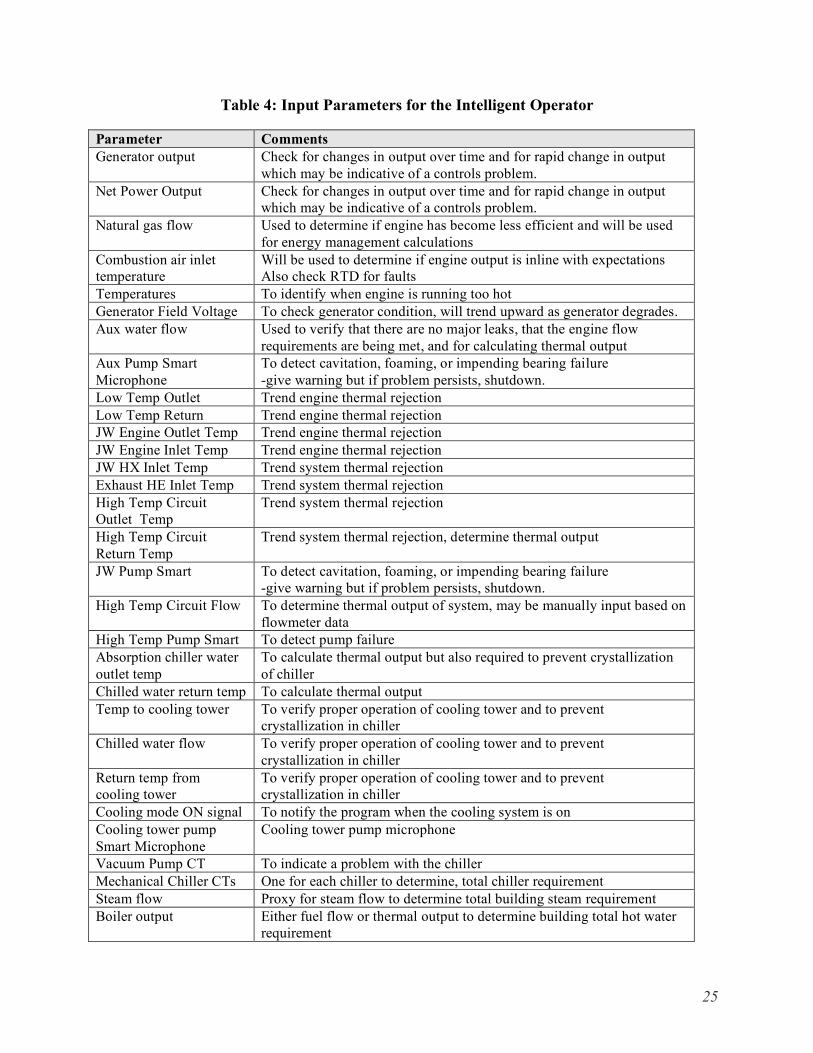
Table 4: Input Parameters for the Intelligent Operator
Parameter Comments Generator output Check for changes in output over time and for rapid change in output
which may be indicative of a controls problem. Net Power Output Check for changes in output over time and for rapid change in output
which may be indicative of a controls problem. Natural gas flow Used to determine if engine has become less efficient and will be used
for energy management calculations Combustion air inlet temperature
Will be used to determine if engine output is inline with expectations Also check RTD for faults
Temperatures To identify when engine is running too hot Generator Field Voltage To check generator condition, will trend upward as generator degrades. Aux water flow Used to verify that there are no major leaks, that the engine flow
requirements are being met, and for calculating thermal output Aux Pump Smart Microphone
To detect cavitation, foaming, or impending bearing failure -give warning but if problem persists, shutdown.
Low Temp Outlet Trend engine thermal rejection Low Temp Return Trend engine thermal rejection JW Engine Outlet Temp Trend engine thermal rejection JW Engine Inlet Temp Trend engine thermal rejection JW HX Inlet Temp Trend system thermal rejection Exhaust HE Inlet Temp Trend system thermal rejection High Temp Circuit Outlet Temp
Trend system thermal rejection
High Temp Circuit Return Temp
Trend system thermal rejection, determine thermal output
JW Pump Smart To detect cavitation, foaming, or impending bearing failure -give warning but if problem persists, shutdown.
High Temp Circuit Flow To determine thermal output of system, may be manually input based on flowmeter data
High Temp Pump Smart To detect pump failure Absorption chiller water outlet temp
To calculate thermal output but also required to prevent crystallization of chiller
Chilled water return temp To calculate thermal output Temp to cooling tower To verify proper operation of cooling tower and to prevent
crystallization in chiller Chilled water flow To verify proper operation of cooling tower and to prevent
crystallization in chiller Return temp from cooling tower
To verify proper operation of cooling tower and to prevent crystallization in chiller
Cooling mode ON signal To notify the program when the cooling system is on Cooling tower pump Smart Microphone
Cooling tower pump microphone
Vacuum Pump CT To indicate a problem with the chiller Mechanical Chiller CTs One for each chiller to determine, total chiller requirement Steam flow Proxy for steam flow to determine total building steam requirement Boiler output Either fuel flow or thermal output to determine building total hot water
requirement
25

10.4 Variable Assignments
The IO will be required to read in data from the various data sources and transfer the data to pre-assigned variables to be used elsewhere in the program.
10.5 Filtering and Averaging
Data from the IO will be gathered from many different sources and will likely need to be filtered or averaged before it will be useful for the rest of the program. In most cases, the engine, CHP system and building data will be averaged over one minute intervals and depending on its use will be averaged on hourly and daily intervals as well. In order to manage the size of the IO’s data storage requirements, the daily database stores 2 years worth of data. The hourly and minute databases will store data for 4 months. It is assumed that the existing data acquisition system will be used as the primary data storage device for the operating data. If the data proves to be particular noisy, other filtering techniques may be required.
10.6 Neural Network Models
Single output back propagating neural network (NN) models will be used for predicting various parameters. The NN models will be used for both optimizing the system and diagnosing problems. Prior work, including stakeholder meetings and failure mode and effects analysis (FMEA), have identified several parameters that are important to assess the state of the engine, CHP system and associated economics. These models will be used to make daily, hourly and by-the-minute predictions. The models are basically a set of weightings generated from a network learning subroutine. Requirements for each NN model are outlined in the Optimization and Diagnostics sections.
10.7 Optimization
The optimization module requires hourly NN predictions for the site’s electric, heating, steam and cooling loads based on the forecasted temperature for the day, the type of day (holiday, weekend, or weekday) and building mode (whether it is configured for heating or cooling). In the case of real time pricing, the same parameters as well as historical pricing will be used to predict electric pricing for the day. The IO will be configured to accept both real time and fixed electric rate structures which will be input by the user. Information on existing equipment at the site will also have to be configured for boilers, heater and chillers. The user will also have to enter O&M costs for the CHP plant and existing equipment. The predicted loads and utility rates will be used to calculate, on an hourly basis, what it would cost on an hourly basis to operate the CHP system and what it would cost to purchase electricity or steam from the utility to meet the site’s needs. Next, the optimization routine will identify blocks of time when it would be economically beneficial to operate the CHP. The blocks of time will be based on minimum operating windows for operating the engine, the engine with heating, and the engine with cooling. For example, the user may decide that the minimum time required to dispatch an engine would be three hours, and four hours for operating the engine with heating or cooling because of the time it takes for the equipment to heat up and to account for wear due to starting and stopping
26

the equipment. The optimization module will report a dispatch schedule and can also generate reports that estimate savings for last year, last quarter, last month, today and tomorrow.
Hourly NN models for loads
Hourly NN models for real time rates (if
req’d)
Forecasted Loads
Forecasted Rates
Current Rate Structure
(user input )
Equipment Performanc e(user input )
• Equipment Schedule • Savings Reports
Cost with CHP
Cost w /o CHP
Cost before CHP
Minimu mOperating
Windows (user input )
Figure 3: Data for Optimization Module
The time interval indicated in Table 5 below is the time step within the NN prediction period. The breadth is the time span of prior data that the NN uses to create the current model. In this case the time span should not be limited so that it only captures the effects of recent building history and recent weather data. The model built from the last 3 weeks of data will use the next day’s forecast to predict the next day’s extremes. This assumes that an extreme day will be forecasted a day ahead by the weather man. In the future it may be useful to build in a function that saves the data from extreme days for future reference.
27

Table 5: Neural Networks Requirements for Optimization Module
Output Inputs Time Interval Breadth
Electric Load Temperature forecast, building mode, type of day, generated
power, imported power hourly 3 weeks
Cooling Load Temperature forecast, building mode, type of day, mechanical
chiller power hourly 3 weeks
Steam Load Temperature forecast, building mode, type of day, boiler load,
and/or steam purchased hourly 3 weeks
Heating Load Temperature forecast, building mode, type of day, boiler load hourly 3 weeks
Spot Electric Price (If required depending on
the site’s rate structure)
Temperature forecast, building mode, type of day hourly 3 weeks
10.8 Diagnostics
The diagnostic portion of the IO requires NN models to predict what parameters should be based on current operating conditions. Neural network models for each diagnostic parameter will be made on a daily basis using the time interval listed in Table 5. Data from each time interval will be used to construct the NN model for that day. NN Models that span back in time according to the breadth in Table 5 will be used to predict what the parameter would have been at the current operating conditions. For example, in looking at fuel flow, NN models will be used to predict what the fuel flow would have been six months ago based on the current operating conditions. Fuel flow outputs from these models will then be used to calculate an average value and standard deviation for fuel flow over the past six months. This figure will change after the model runs are done to fine tune the diagnostics, but initially a six month period is a good starting point for the initial modeling. If the current fuel flow differs by more than one standard deviation for outputs from the historic models, a warning or alarm will appear on the monitoring screen or an e-mail can be sent.
Past NN
models for
parameter
Current
Conditions
Current
Parameter
Value
Expected Outputs
Based on Historic
Models
Comparison to Linear
Regression and Standard
Deviations of Historic Models
Warnings ,
Alarms , e-mail
notices ,
Reports
Figure 4: Data Flow for Diagnostics
28
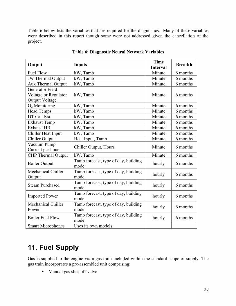
Table 6 below lists the variables that are required for the diagnostics. Many of these variables were described in this report though some were not addressed given the cancellation of the project.
Table 6: Diagnostic Neural Network Variables
Output Inputs Time Interval Breadth
Fuel Flow kW, Tamb Minute 6 months JW Thermal Output kW, Tamb Minute 6 months Aux Thermal Output kW, Tamb Minute 6 months Generator Field Voltage or Regulator Output Voltage
kW, Tamb Minute 6 months
O2 Monitoring kW, Tamb Minute 6 months Head Temps kW, Tamb Minute 6 months DT Catalyst kW, Tamb Minute 6 months Exhaust Temp kW, Tamb Minute 6 months Exhaust HR kW, Tamb Minute 6 months Chiller Heat Input kW, Tamb Minute 6 months Chiller Output Heat Input, Tamb Minute 6 months Vacuum Pump Current per hour Chiller Output, Hours Minute 6 months
CHP Thermal Output kW, Tamb Minute 6 months
Boiler Output Tamb forecast, type of day, building mode hourly 6 months
Mechanical Chiller Output
Tamb forecast, type of day, building mode hourly 6 months
Steam Purchased Tamb forecast, type of day, building mode hourly 6 months
Imported Power Tamb forecast, type of day, building mode hourly 6 months
Mechanical Chiller Power
Tamb forecast, type of day, building mode hourly 6 months
Boiler Fuel Flow Tamb forecast, type of day, building mode hourly 6 months
Smart Microphones Uses its own models
11. Fuel Supply Gas is supplied to the engine via a gas train included within the standard scope of supply. The gas train incorporates a pre-assembled unit comprising:
• Manual gas shut-off valve
29
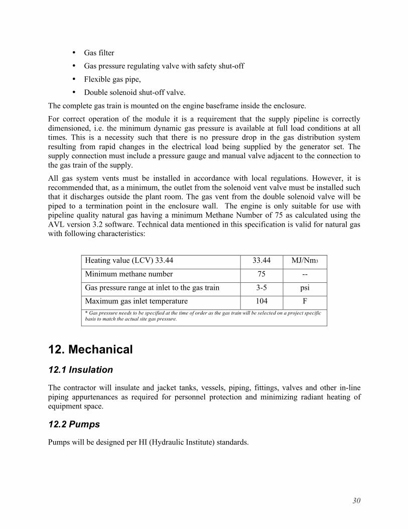
• Gas filter • Gas pressure regulating valve with safety shut-off
• Flexible gas pipe, • Double solenoid shut-off valve.
The complete gas train is mounted on the engine baseframe inside the enclosure. For correct operation of the module it is a requirement that the supply pipeline is correctly dimensioned, i.e. the minimum dynamic gas pressure is available at full load conditions at all times. This is a necessity such that there is no pressure drop in the gas distribution system resulting from rapid changes in the electrical load being supplied by the generator set. The supply connection must include a pressure gauge and manual valve adjacent to the connection to the gas train of the supply. All gas system vents must be installed in accordance with local regulations. However, it is recommended that, as a minimum, the outlet from the solenoid vent valve must be installed such that it discharges outside the plant room. The gas vent from the double solenoid valve will be piped to a termination point in the enclosure wall. The engine is only suitable for use with pipeline quality natural gas having a minimum Methane Number of 75 as calculated using the AVL version 3.2 software. Technical data mentioned in this specification is valid for natural gas with following characteristics:
Heating value (LCV) 33.44 33.44 MJ/Nm3
Minimum methane number 75 --
Gas pressure range at inlet to the gas train 3-5 psi
Maximum gas inlet temperature 104 F * Gas pressure needs to be specified at the time of order as the gas train will be selected on a project specific basis to match the actual site gas pressure.
12. Mechanical 12.1 Insulation
The contractor will insulate and jacket tanks, vessels, piping, fittings, valves and other in-line piping appurtenances as required for personnel protection and minimizing radiant heating of equipment space.
12.2 Pumps
Pumps will be designed per HI (Hydraulic Institute) standards.
30

12.3 Valves Marking
Valves will be compatible and functional with system design and application.
All valves will be numbered and tagged with an 18 gauge brass tag, 1” minimum diameter, polished and lacquered, with stamped lettering and numbers filled with black paint and secured to the valve stem with a 12 gauge hard brass wire “S” hook. A valve list (schedule) showing the respective services in duplicate will be furnished describing each valve number, location and service.
12.4 Freeze Protection
The contractor is responsible for the purchase of 50/50% Ethylene Glycol solution with appropriate corrosion inhibitor and filling of all cooling systems. If contractor elects to mix solution on site, the water will be distilled and will not contain chlorine. Corrosion inhibitors will be as required by the genset manufacturer to protect against corrosion and be non-acid forming at genset operating temperatures.
12.5 Lubrication
The types of lubrication provided by the contractor for the plant equipment will comply with the recommendations of the equipment manufacturers.
12.6 Lifting and Handling Systems
Contractor will design, furnish and permanently install lifting and handling systems as required to service major equipment that requires maintenance in accordance with manufacturers suggested recommendations.
13. Quality 13.1 Good Industry and Engineering Practices
The design for the System will comply with those practices, methods and standards of engineering, design, manufacture, construction, performance, operations, maintenance and safety including but not limited to all federal, state and local and professional codes and standards, which, in the exercise of reasonable judgment and consistent with industry and professional engineering, construction, operating, maintenance and safety practices, and with the standards of good workmanship, would be expected to be utilized by a person engaged in the same type of undertaking under the same or similar circumstances.
13.2 Certifications
NEC (NFPA70) where applicable.
UL2200: Component and assemblies must be capable of UL2200 certification but attainment of that certification is not part of the initial project scope.
31
13.3 Factory Tests and Reports
Standard factory tests will be performed on each unit. A standard factory test report should be included with each unit.
14. Serviceability Ease of access or maximum time to get to certain parts or service items such as oil filters, air filters, and diagnostic ports.
15. Safety Features • Methane and CO detection • 6 Air turns per minute
• Fuel system vents
32
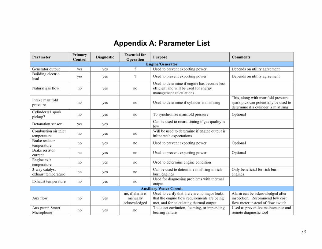
Appendix A: Parameter List Parameter
Generator output
Primary Control
yes
Diagnostic
yes
Essential for Operation
En?
Purpose
gine/Generator Used to prevent exporting power
Comments
Depends on utility agreement Building electric load yes yes ? Used to prevent exporting power Depends on utility agreement
Natural gas flow no yes no Used to determine if engine has become less efficient and will be used for energy management calculations
Intake manifold pressure no yes no Used to determine if cylinder is misfiring
This, along with manifold pressure spark pick can potentially be used to determine if a cylinder is misfiring
Cylinder #1 spark pickup? no yes no To synchronize manifold pressure Optional
Detonation sensor yes yes Can be used to retard timing if gas quality is low
Combustion air inlet temperature no yes no Will be used to determine if engine output is
inline with expectations Brake resistor temperature no yes no Used to prevent exporting power Optional
Brake resistor current no yes no Used to prevent exporting power Optional
Engine exit temperature no yes no Used to determine engine condition
3-way catalyst exhaust temperature no yes no Can be used to determine misfiring in rich
burn engines Only beneficial for rich burn engines
Exhaust temperature
Aux flow
no
no
yes
yes
no
Auxilno, if alarm is
manually acknowledged
Used for diagnosing problems with thermal output
iary Water Circuit Used to verify that there are no major leaks, that the engine flow requirements are being met, and for calculating thermal output
Alarm can be acknowledged after inspection. Recommend low cost flow meter instead of flow switch
Aux pump Smart Microphone no yes no To detect cavitation, foaming, or impending
bearing failure Used as preventive maintenance and remote diagnostic tool
33
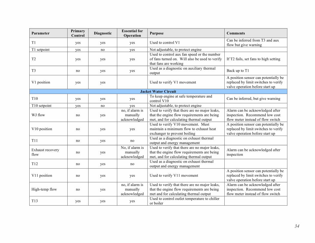
Parameter Primary Control Diagnostic Essential for
Operation Purpose Comments
T1 yes yes yes Used to control V1 Can be inferred from T3 and aux flow but give warning
T1 setpoint yes no yes Not adjustable, to protect engine
T2 yes yes yes Used to control aux fan speed or the number of fans turned on. Will also be used to verify that fans are working
If T2 fails, set fans to high setting
T3 no yes yes Used as a diagnostic on auxiliary thermal output Back up to T1
V1 position yes yes Used to verify V1 movement A position sensor can potentially be replaced by limit switches to verify valve operation before start up
Jacket Water Circuit
T10 yes yes yes To keep engine at safe temperature and control V10 Can be inferred, but give warning
T10 setpoint yes no yes Not adjustable, to protect engine
WJ flow no yes no, if alarm is
manually acknowledged
Used to verify that there are no major leaks, that the engine flow requirements are being met, and for calculating thermal output
Alarm can be acknowledged after inspection. Recommend low cost flow meter instead of flow switch
V10 position no yes yes Used to verify V10 movement. Must maintain a minimum flow to exhaust heat exchanger to prevent boiling
A position sensor can potentially be replaced by limit switches to verify valve operation before start up
T11 no yes no Used as a diagnostic on exhaust thermal output and energy management
Exhaust recovery flow no yes
No, if alarm is manually
acknowledged
Used to verify that there are no major leaks, that the engine flow requirements are being met, and for calculating thermal output
Alarm can be acknowledged after inspection
T12 no yes no Used as a diagnostic on exhaust thermal output and energy management
V11 position no yes yes Used to verify V11 movement A position sensor can potentially be replaced by limit switches to verify valve operation before start up
High-temp flow no yes no, if alarm is
manually acknowledged
Used to verify that there are no major leaks, that the engine flow requirements are being met and for calculating thermal output
Alarm can be acknowledged after inspection. Recommend low cost flow meter instead of flow switch
T13 yes yes yes Used to control outlet temperature to chiller or boiler
34
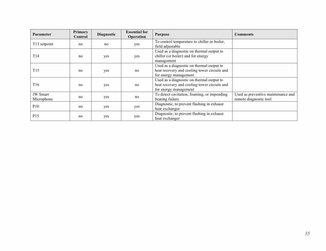
Parameter Primary Control Diagnostic Essential for
Operation Purpose Comments
T13 setpoint no no yes To control temperature to chiller or boiler, field adjustable
T14 no yes yes Used as a diagnostic on thermal output to chiller (or boiler) and for energy management
T15 no yes no Used as a diagnostic on thermal output to heat recovery and cooling tower circuits and for energy management
T16 no yes no Used as a diagnostic on thermal output to heat recovery and cooling tower circuits and for energy management
JW Smart Microphone no yes no To detect cavitation, foaming, or impending
bearing failure Used as preventive maintenance and remote diagnostic tool
P10 no yes yes Diagnostic, to prevent flashing in exhaust heat exchanger
P15 no yes yes Diagnostic, to prevent flashing in exhaust heat exchanger
35
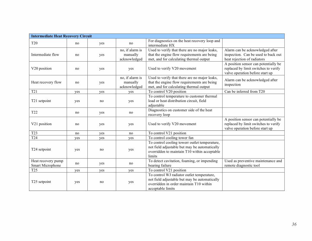
Intermediate Heat Recovery Circuit
T20 no yes no For diagnostics on the heat recovery loop and intermediate HX
Intermediate flow no yes no, if alarm is
manually acknowledged
Used to verify that there are no major leaks, that the engine flow requirements are being met, and for calculating thermal output
Alarm can be acknowledged after inspection. Can be used to back out heat rejection of radiators
V20 position no yes yes Used to verify V20 movement A position sensor can potentially be replaced by limit switches to verify valve operation before start up
Heat recovery flow no yes no, if alarm is
manually acknowledged
Used to verify that there are no major leaks, that the engine flow requirements are being met, and for calculating thermal output
Alarm can be acknowledged after inspection
T21 yes yes yes To control V20 position Can be inferred from T20
T21 setpoint yes no yes To control temperature to customer thermal load or heat distribution circuit, field adjustable
T22 no yes no Diagnostics on customer side of the heat recovery loop
V21 position no yes yes Used to verify V20 movement A position sensor can potentially be replaced by limit switches to verify valve operation before start up
T23 no yes no To control V21 position T24 yes yes yes To control cooling tower fan
T24 setpoint yes no yes
To control cooling towerr outlet temperature, not field adjustable but may be automatically overridden to maintain T10 within acceptable limits
Heat recovery pump Smart Microphone no yes no To detect cavitation, foaming, or impending
bearing failure Used as preventive maintenance and remote diagnostic tool
T25 yes yes yes To control V21 position
T25 setpoint yes no yes
To control WJ radiator outlet temperature, not field adjustable but may be automatically overridden in order maintain T10 within acceptable limits
36