Embed Size (px)
Citation preview
ITU-T G.8032 Ethernet Ring Protection Switching
The ITU-TG.8032 Ethernet Ring Protection Switching feature implements protection switchingmechanismsfor Ethernet layer ring topologies. This feature uses the G.8032 Ethernet Ring Protection (ERP) protocol,defined in ITU-T G.8032, to provide protection for Ethernet traffic in a ring topology, while ensuring thatno loops are within the ring at the Ethernet layer. The loops are prevented by blocking traffic on either apredetermined link or a failed link.
• Finding Feature Information, page 1
• Prerequisites for Configuring ITU-T G.8032 Ethernet Ring Protection Switching, page 1
• Restrictions for ITU-T G.8032 Ethernet Ring Protection Switching, page 2
• About ITU-T G.8032 Ethernet Ring Protection Switching, page 2
• How to Configure ITU-T G.8032 Ethernet Ring Protection Switching, page 8
• Configuration Examples for ITU-T G.8032 Ethernet Ring Protection Switching, page 20
• Additional References for ITU-T G.8032 Ethernet Ring Protection Switching , page 22
• Feature Information For ITU-T G.8032 Ethernet Ring Protection Switching, page 23
Finding Feature InformationYour software release may not support all the features documented in this module. For the latest caveats andfeature information, see Bug Search Tool and the release notes for your platform and software release. Tofind information about the features documented in this module, and to see a list of the releases in which eachfeature is supported, see the feature information table.
Use Cisco Feature Navigator to find information about platform support and Cisco software image support.To access Cisco Feature Navigator, go to www.cisco.com/go/cfn. An account on Cisco.com is not required.
Prerequisites for Configuring ITU-T G.8032 Ethernet RingProtection Switching
• The Ethernet Flow Points (EFPs) and Trunk Ethernet Flow Points (TEFPs) must be configured.
Carrier Ethernet Configuration Guide, Cisco IOS XE Release 3S 1
Restrictions for ITU-T G.8032 Ethernet Ring Protection Switching• G.8032 ERP is supported only on Trunk EFP service instances.
• G.8032 support is claimed only over the normal interfaces and not on the port-channels.
About ITU-T G.8032 Ethernet Ring Protection Switching
Ring Protection LinksAn Ethernet ring consists of multiple Ethernet ring nodes. Each Ethernet ring node is connected to adjacentEthernet ring nodes using two independent ring links. A ring link prohibits formation of loops that affect thenetwork. The Ethernet ring uses a specific link to protect the entire Ethernet ring. This specific link is calledthe Ring Protection Link (RPL). A ring link is bound by two adjacent Ethernet ring nodes and a port for aring link (also known as a ring port). There must be at least two Ethernet ring nodes in a Ethernet ring.
ITU-T G.8032 Ethernet Ring Protection Switching FunctionalityThe Ethernet ring protection functionality includes the following:
• Loop avoidance
• The use of learning, forwarding, and Filtering Database (FDB) mechanisms
Loop avoidance in an Ethernet ring is achieved by ensuring that, at any time, traffic flows on all but the RingProtection Link (RPL).
The following is a list of RPL types (or RPL nodes) and their functions:
• RPL owner—Responsible for blocking traffic over the RPL so that no loops are formed in the Ethernettraffic. There can be only one RPL owner in a ring.
• RPL neighbor node—An Ethernet ring node adjacent to the RPL. It is responsible for blocking its endof the RPL under normal conditions. This node type is optional and prevents RPL usage when protected.
• RPL next-neighbor node—Next-neighbor node is an Ethernet ring node adjacent to an RPL owner nodeor RPL neighbor node. It is mainly used for FDB flush optimization on the ring. This node is alsooptional.
Carrier Ethernet Configuration Guide, Cisco IOS XE Release 3S2
ITU-T G.8032 Ethernet Ring Protection SwitchingRestrictions for ITU-T G.8032 Ethernet Ring Protection Switching
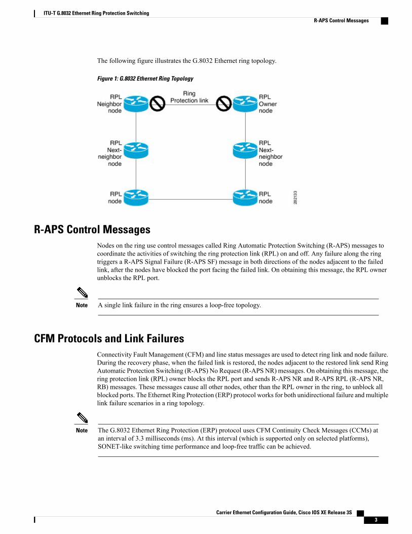
The following figure illustrates the G.8032 Ethernet ring topology.
Figure 1: G.8032 Ethernet Ring Topology
R-APS Control MessagesNodes on the ring use control messages called Ring Automatic Protection Switching (R-APS) messages tocoordinate the activities of switching the ring protection link (RPL) on and off. Any failure along the ringtriggers a R-APS Signal Failure (R-APS SF) message in both directions of the nodes adjacent to the failedlink, after the nodes have blocked the port facing the failed link. On obtaining this message, the RPL ownerunblocks the RPL port.
A single link failure in the ring ensures a loop-free topology.Note
CFM Protocols and Link FailuresConnectivity Fault Management (CFM) and line status messages are used to detect ring link and node failure.During the recovery phase, when the failed link is restored, the nodes adjacent to the restored link send RingAutomatic Protection Switching (R-APS) No Request (R-APS NR) messages. On obtaining this message, thering protection link (RPL) owner blocks the RPL port and sends R-APS NR and R-APS RPL (R-APS NR,RB) messages. These messages cause all other nodes, other than the RPL owner in the ring, to unblock allblocked ports. The Ethernet Ring Protection (ERP) protocol works for both unidirectional failure and multiplelink failure scenarios in a ring topology.
The G.8032 Ethernet Ring Protection (ERP) protocol uses CFM Continuity Check Messages (CCMs) atan interval of 3.3 milliseconds (ms). At this interval (which is supported only on selected platforms),SONET-like switching time performance and loop-free traffic can be achieved.
Note
Carrier Ethernet Configuration Guide, Cisco IOS XE Release 3S 3
ITU-T G.8032 Ethernet Ring Protection SwitchingR-APS Control Messages
G.8032 Ring-Supported Commands and FunctionalityA G.8032 ring supports these basic operator administrative commands:
• Force switch (FS)—Allows the operator to forcefully block a particular ring port. Note the followingpoints about FS commands:
• Effective even if there is an existing SF condition
• Multiple FS commands for ring are supported
• May be used to allow immediate maintenance operations
• Manual switch (MS)—Allows the operator to manually block a particular ring port. Note the followingpoints about MS commands:
• Ineffective in an existing FS or signal failure (SF) condition
• Overridden by new FS or SF conditions
• Multiple MS commands cancel all MS commands
• Clear—Cancels an existing FS or MS command on the ring port. The Clear command is used at the ringprotection link (RPL) owner to clear a nonrevertive mode condition.
A G.8032 ring can support multiple instances. An instance is a logical ring running over a physical ring. Suchinstances are used for various reasons, such as load-balancing VLANs over a ring. For example, odd-numberedVLANsmay go in one direction of the ring, and even-numbered VLANsmay go in the other direction. SpecificVLANs can be configured under only one instance. They cannot overlap multiple instances. Otherwise, datatraffic or Ring Automatic Protection Switching (R-APS) messages may cross logical rings, which is notdesirable.
G.8032 ERP TimersThe G.8032 Ethernet Ring Protection (ERP) protocol specifies the use of different timers to avoid raceconditions and unnecessary switching operations:
• Delay timers—Used by the Ring Protection Link (RPL) owner to verify that the network has stabilizedbefore blocking the RPL. Note the following points about delay timers.
• After a signal failure (SF) condition, a Wait-to-Restore (WTR) timer is used to verify that the SFis not intermittent.
• The WTR timer can be configured by the operator. The default time interval is 5 minutes; the timeinterval ranges from 1 to 12 minutes.
• After a force switch (FS) or a manual switch (MS) command is issued, a Wait-to-Block (WTB)timer is used to verify that no background condition exists.
The WTB timer interval may be shorter than the WTR timer interval.Note
Carrier Ethernet Configuration Guide, Cisco IOS XE Release 3S4
ITU-T G.8032 Ethernet Ring Protection SwitchingG.8032 Ring-Supported Commands and Functionality
• Guard timer—Used by all nodes when changing state; the guard timer blocks latent outdated messagesfrom causing unnecessary state changes. The guard timer can be configured. The default time intervalis 500 ms; the time interval ranges from 10 to 2000 ms.
• Hold-off timers—Used by the underlying Ethernet layer to filter out intermittent link faults. The hold-offtimer can be configured. The default time interval is 0 seconds; the time interval ranges from 0 to 10seconds. Faults are reported to the ring protection mechanism only if this timer expires.
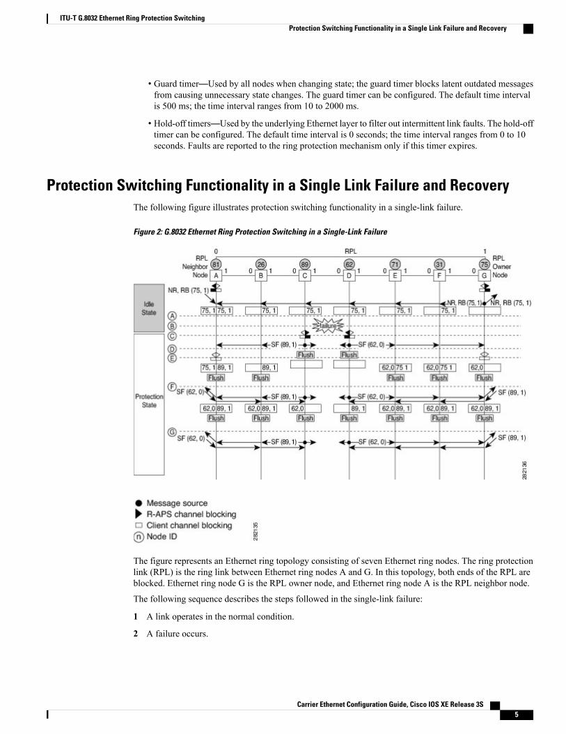
Protection Switching Functionality in a Single Link Failure and RecoveryThe following figure illustrates protection switching functionality in a single-link failure.
Figure 2: G.8032 Ethernet Ring Protection Switching in a Single-Link Failure
The figure represents an Ethernet ring topology consisting of seven Ethernet ring nodes. The ring protectionlink (RPL) is the ring link between Ethernet ring nodes A and G. In this topology, both ends of the RPL areblocked. Ethernet ring node G is the RPL owner node, and Ethernet ring node A is the RPL neighbor node.
The following sequence describes the steps followed in the single-link failure:
1 A link operates in the normal condition.
2 A failure occurs.
Carrier Ethernet Configuration Guide, Cisco IOS XE Release 3S 5
ITU-T G.8032 Ethernet Ring Protection SwitchingProtection Switching Functionality in a Single Link Failure and Recovery
3 Ethernet ring nodes C and D detect a local signal failure (SF) condition and after the hold-off time interval,block the failed ring port and perform the FDB flush.
4 Ethernet ring nodes C and D start sending Ring Automatic Protection Switching (R-APS) SF messagesperiodically along with the (node ID and bidirectional path-protected ring (BPR) identifier pair) on bothring ports while the SF condition persists.
5 All Ethernet ring nodes receiving an R-APS SF message perform the FDB flush. When the RPL ownernode G and RPL neighbor node A receive an R-APS SF message, the Ethernet ring node unblocks its endof the RPL and performs the FDB flush.
6 All Ethernet ring nodes receiving a second R-APS SFmessage perform the FDB flush again; the additionalFDB flush is because of the node ID and BPR-based configuration.
7 R-APS SF messages are detected on the Ethernet Ring indicating a stable SF condition. Further R-APSSF messages trigger no further action.
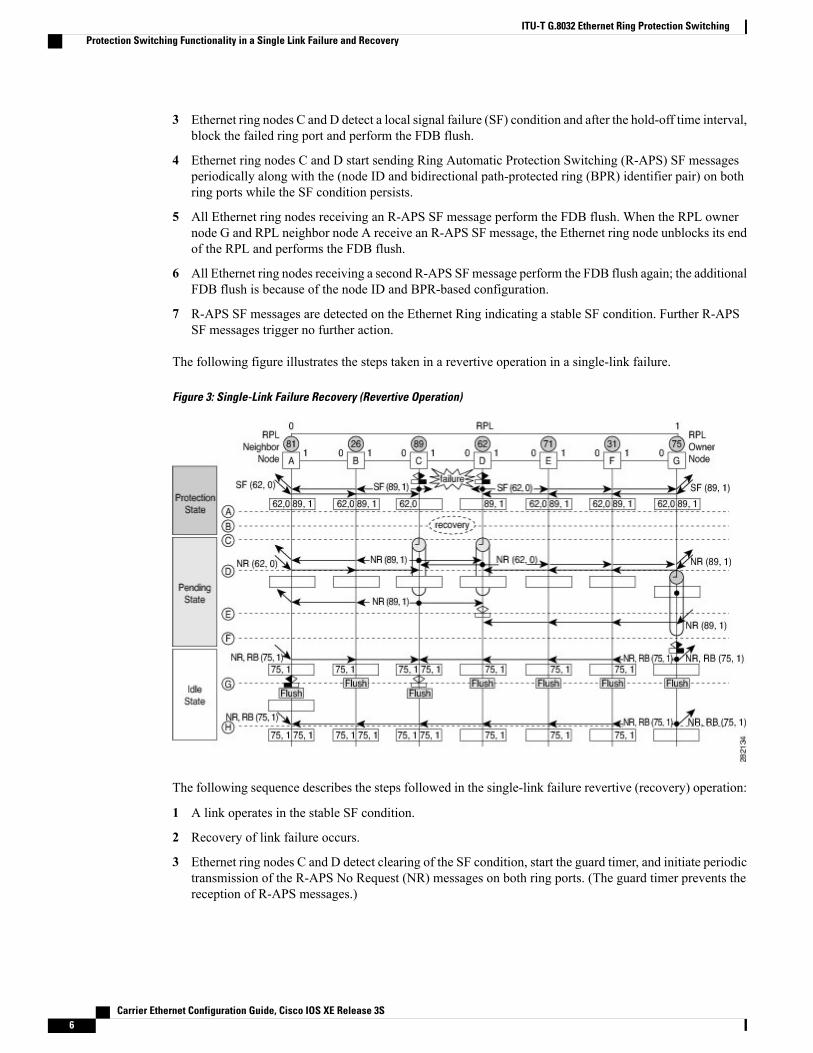
The following figure illustrates the steps taken in a revertive operation in a single-link failure.
Figure 3: Single-Link Failure Recovery (Revertive Operation)
The following sequence describes the steps followed in the single-link failure revertive (recovery) operation:
1 A link operates in the stable SF condition.
2 Recovery of link failure occurs.
3 Ethernet ring nodes C and D detect clearing of the SF condition, start the guard timer, and initiate periodictransmission of the R-APS No Request (NR) messages on both ring ports. (The guard timer prevents thereception of R-APS messages.)
Carrier Ethernet Configuration Guide, Cisco IOS XE Release 3S6
ITU-T G.8032 Ethernet Ring Protection SwitchingProtection Switching Functionality in a Single Link Failure and Recovery
4 When the Ethernet ring nodes receive an R-APS NR message, the node ID and BPR identifier pair of areceiving ring port is deleted and the RPL owner node starts the Wait-to-Restore (WTR) timer.
5 When the guard timer expires on Ethernet ring nodes C and D, the nodes may accept the new R-APSmessages, if any. Ethernet ring node D receives an R-APSNRmessage with a higher node ID from Ethernetring node C, and unblocks its nonfailed ring port.
6 When the WTR timer expires, the RPL owner node blocks its end of the RPL, sends R-APS (NR or routeblocked [RB]) message with the (node ID and BPR identifier pair), and performs the FDB flush.
7 When Ethernet ring node C receives an R-APS (NR or RB) message, the node removes the block on itsblocked ring ports, and stops sending R-APS NR messages. On the other hand, when the RPL neighbornode A receives an R-APS NR or RB message, the node blocks its end of the RPL. In addition, Ethernetring nodes A to F perform the FDB flush when receiving an RAPS NR or RB message because of thenode ID and BPR-based configuration.
Ethernet Flow PointsAn Ethernet flow point (EFP) is a forwarding decision point in the provider edge (PE) router, which givesnetwork designers flexibility to make many Layer 2 flow decisions within the interface. Many EFPs can beconfigured on a single physical port. (The number varies from one device to another.) EFPs are the logicaldemarcation points of an Ethernet virtual connection (EVC) on an interface. An EVC that uses two or moreuser network interfaces (UNIs) requires an EFP on the associated ingress and egress interfaces of every devicethat the EVC passes through.
EFPs can be configured on any Layer 2 traffic port; however, they are usually configured on UNI ports. Thefollowing parameters (matching criteria) can be configured on the EFP:
• Frames of a specific VLAN, a VLAN range, or a list of VLANs (100-150 or 100,103,110)
• Frames with no tags (untagged)
• Frames with identical double-tags (VLAN tags) as specified
• Frames with identical Class of Service (CoS) values
A frame passes each configured match criterion until the correct matching point is found. If a frame does notfit any of the matching criteria, it is dropped. Default criteria can be configured to avoid dropping frames.
The following types of commands can be used in an EFP:
• Rewrite commands—In each EFP, VLAN tag management can be specified with the following actions:
• Pop—1) pops out a tag; 2) pops out two tags
• Push—1) pushes in a tag; 2) pushes in two tags
• Translate—1 to 1) changes a tag value; 1 to 2) pops one tag and pushes two tags; 2 to 1) pops twotags and pushes one tag; 2 to 2) changes the value for two tags
• Forwarding commands—Each EFP specifies the forwarding command for the frames that enter the EFP.Only one forwarding command can be configured per EFP. The forwarding options are as follows:
• Layer 2 point-to-point forwarding to a pseudowire tunnel
• Multipoint bridge forwarding to a bridge domain entity
Carrier Ethernet Configuration Guide, Cisco IOS XE Release 3S 7
ITU-T G.8032 Ethernet Ring Protection SwitchingEthernet Flow Points
• Local switch-to-switch forwarding between two different interfaces
• Feature commands—In each EFP, the QoS features or parameters can be changed and the ACL can beupdated.
Service Instances and Associated EFPsConfiguring a service instance on a Layer 2 port creates a pseudoport or EFP on which you configure EVCfeatures. Each service instance has a unique number per interface, but you can use the same number on differentinterfaces because service instances on different ports are not related.
An EFP classifies frames from the same physical port to one of the multiple service instances associated withthat port, based on user-defined criteria. Each EFP can be associated with different forwarding actions andbehavior.
When an EFP is created, the initial state is UP. The state changes to DOWN under the following circumstances:
• The EFP is explicitly shut down by a user.
• The main interface to which the EFP is associated is down or removed.
• If the EFP belongs to a bridge domain, the bridge domain is down.
• The EFP is forced down as an error-prevention measure of certain features.
Use the service instance ethernet interface configuration command to create an EFP on a Layer 2 interfaceand to enter service instance configuration mode. Service instance configuration mode is used to configureall management and control data plane attributes and parameters that apply to the service instance on aper-interface basis. The service instance number is the EFP identifier.
After the device enters service instance configuration mode, you can configure these options:
• default--Sets a command to its defaults
• description--Adds a service instance-specific description
• encapsulation--Configures Ethernet frame match criteria
• exit--Exits from service instance configuration mode
• no--Negates a command or sets its defaults
• shutdown--Takes the service instance out of service
How to Configure ITU-T G.8032 Ethernet Ring ProtectionSwitching
Configuring the Ethernet Ring ProfileTo configure the Ethernet ring profile, complete the following steps.
Carrier Ethernet Configuration Guide, Cisco IOS XE Release 3S8
ITU-T G.8032 Ethernet Ring Protection SwitchingService Instances and Associated EFPs
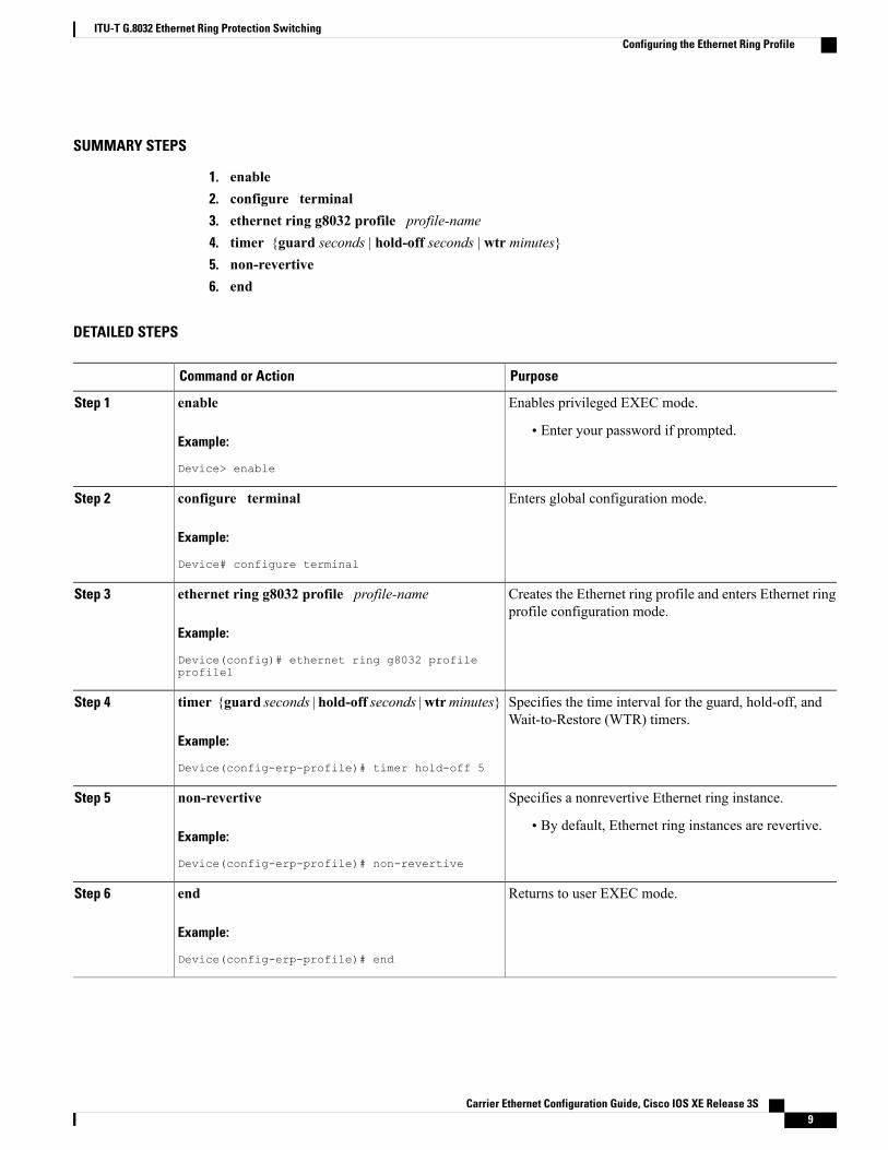
SUMMARY STEPS
1. enable2. configure terminal3. ethernet ring g8032 profile profile-name4. timer {guard seconds | hold-off seconds | wtr minutes}5. non-revertive6. end
DETAILED STEPS
PurposeCommand or Action
Enables privileged EXEC mode.enableStep 1
Example:
Device> enable
• Enter your password if prompted.
Enters global configuration mode.configure terminal
Example:
Device# configure terminal
Step 2
Creates the Ethernet ring profile and enters Ethernet ringprofile configuration mode.
ethernet ring g8032 profile profile-name
Example:
Device(config)# ethernet ring g8032 profileprofile1
Step 3
Specifies the time interval for the guard, hold-off, andWait-to-Restore (WTR) timers.
timer {guard seconds | hold-off seconds |wtrminutes}
Example:
Device(config-erp-profile)# timer hold-off 5
Step 4
Specifies a nonrevertive Ethernet ring instance.non-revertive
Example:
Device(config-erp-profile)# non-revertive
Step 5
• By default, Ethernet ring instances are revertive.
Returns to user EXEC mode.end
Example:
Device(config-erp-profile)# end
Step 6
Carrier Ethernet Configuration Guide, Cisco IOS XE Release 3S 9
ITU-T G.8032 Ethernet Ring Protection SwitchingConfiguring the Ethernet Ring Profile
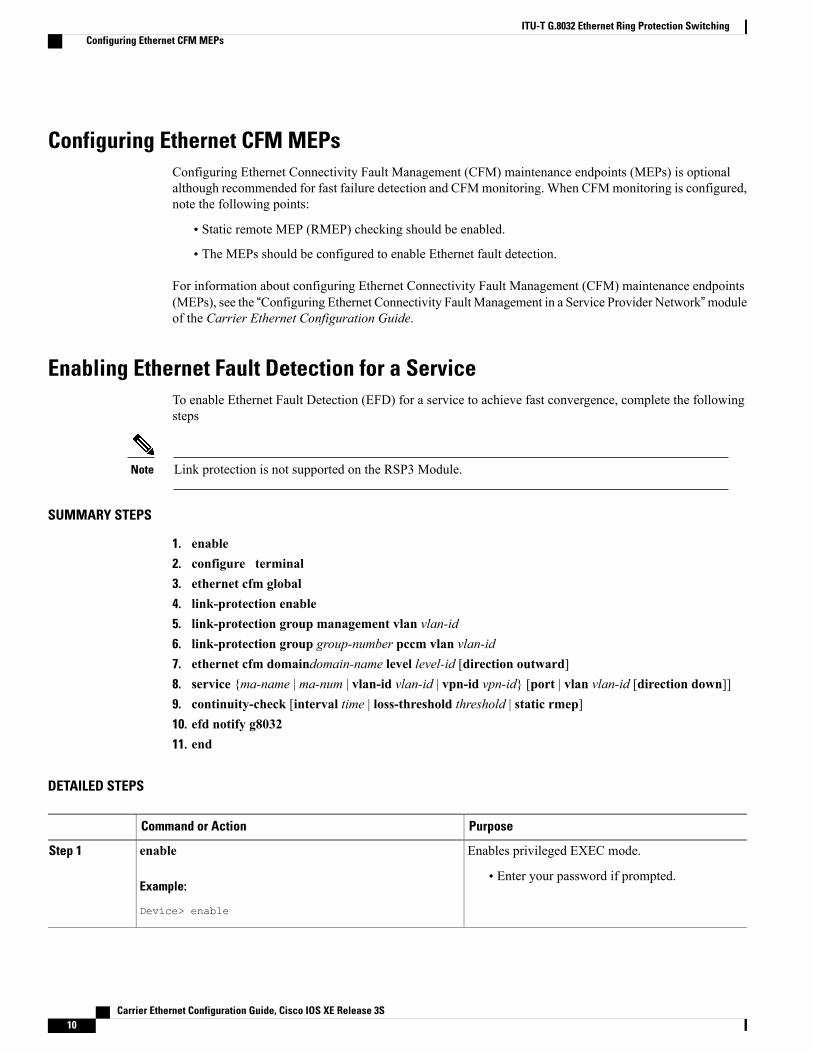
Configuring Ethernet CFM MEPsConfiguring Ethernet Connectivity Fault Management (CFM) maintenance endpoints (MEPs) is optionalalthough recommended for fast failure detection and CFMmonitoring. When CFMmonitoring is configured,note the following points:
• Static remote MEP (RMEP) checking should be enabled.
• The MEPs should be configured to enable Ethernet fault detection.
For information about configuring Ethernet Connectivity Fault Management (CFM) maintenance endpoints(MEPs), see the “Configuring Ethernet Connectivity FaultManagement in a Service Provider Network”moduleof the Carrier Ethernet Configuration Guide.
Enabling Ethernet Fault Detection for a ServiceTo enable Ethernet Fault Detection (EFD) for a service to achieve fast convergence, complete the followingsteps
Link protection is not supported on the RSP3 Module.Note
SUMMARY STEPS
1. enable2. configure terminal3. ethernet cfm global4. link-protection enable5. link-protection group management vlan vlan-id6. link-protection group group-number pccm vlan vlan-id7. ethernet cfm domaindomain-name level level-id [direction outward]8. service {ma-name | ma-num | vlan-id vlan-id | vpn-id vpn-id} [port | vlan vlan-id [direction down]]9. continuity-check [interval time | loss-threshold threshold | static rmep]10. efd notify g803211. end
DETAILED STEPS
PurposeCommand or Action
Enables privileged EXEC mode.enableStep 1
Example:
Device> enable
• Enter your password if prompted.
Carrier Ethernet Configuration Guide, Cisco IOS XE Release 3S10
ITU-T G.8032 Ethernet Ring Protection SwitchingConfiguring Ethernet CFM MEPs
PurposeCommand or Action
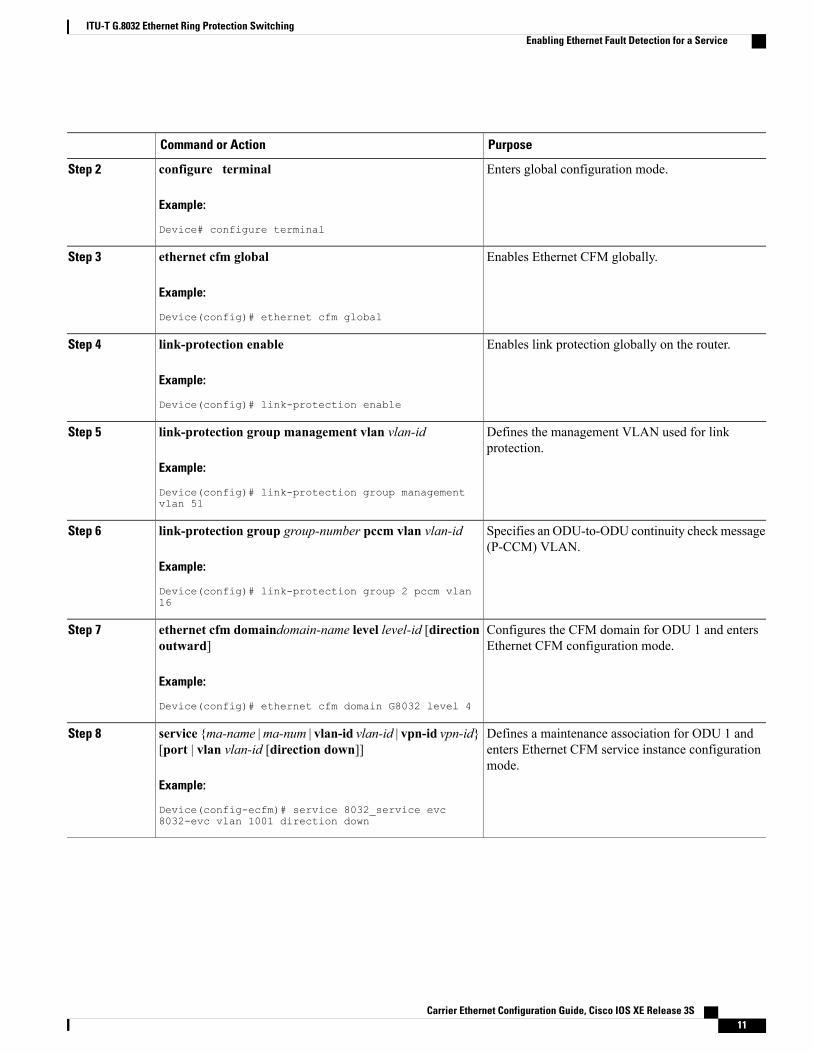
Enters global configuration mode.configure terminal
Example:
Device# configure terminal
Step 2
Enables Ethernet CFM globally.ethernet cfm global
Example:
Device(config)# ethernet cfm global
Step 3
Enables link protection globally on the router.link-protection enable
Example:
Device(config)# link-protection enable
Step 4
Defines the management VLAN used for linkprotection.
link-protection group management vlan vlan-id
Example:
Device(config)# link-protection group managementvlan 51
Step 5
Specifies an ODU-to-ODU continuity checkmessage(P-CCM) VLAN.
link-protection group group-number pccm vlan vlan-id
Example:
Device(config)# link-protection group 2 pccm vlan16
Step 6
Configures the CFM domain for ODU 1 and entersEthernet CFM configuration mode.
ethernet cfm domaindomain-name level level-id [directionoutward]
Example:
Device(config)# ethernet cfm domain G8032 level 4
Step 7
Defines a maintenance association for ODU 1 andenters Ethernet CFM service instance configurationmode.
service {ma-name |ma-num | vlan-id vlan-id | vpn-id vpn-id}[port | vlan vlan-id [direction down]]
Example:
Device(config-ecfm)# service 8032_service evc8032-evc vlan 1001 direction down
Step 8
Carrier Ethernet Configuration Guide, Cisco IOS XE Release 3S 11
ITU-T G.8032 Ethernet Ring Protection SwitchingEnabling Ethernet Fault Detection for a Service
PurposeCommand or Action
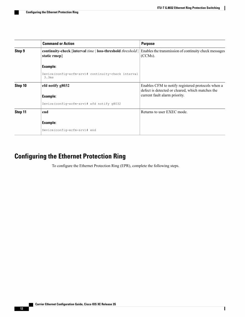
Enables the transmission of continuity checkmessages(CCMs).
continuity-check [interval time | loss-threshold threshold |static rmep]
Example:
Device(config-ecfm-srv)# continuity-check interval3.3ms
Step 9
Enables CFM to notify registered protocols when adefect is detected or cleared, which matches thecurrent fault alarm priority.
efd notify g8032
Example:
Device(config-ecfm-srv)# efd notify g8032
Step 10
Returns to user EXEC mode.end
Example:
Device(config-ecfm-srv)# end
Step 11
Configuring the Ethernet Protection RingTo configure the Ethernet Protection Ring (EPR), complete the following steps.
Carrier Ethernet Configuration Guide, Cisco IOS XE Release 3S12
ITU-T G.8032 Ethernet Ring Protection SwitchingConfiguring the Ethernet Protection Ring
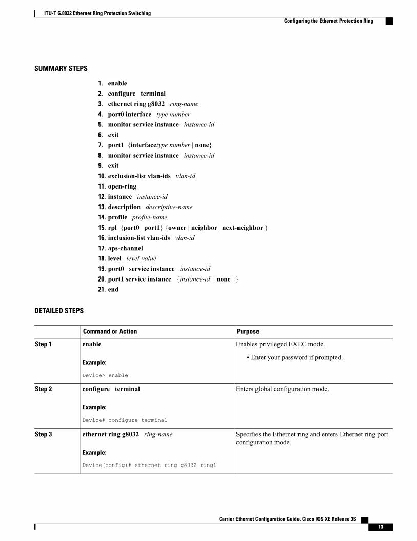
SUMMARY STEPS
1. enable2. configure terminal3. ethernet ring g8032 ring-name4. port0 interface type number5. monitor service instance instance-id6. exit7. port1 {interfacetype number | none}8. monitor service instance instance-id9. exit10. exclusion-list vlan-ids vlan-id11. open-ring12. instance instance-id13. description descriptive-name14. profile profile-name15. rpl {port0 | port1} {owner | neighbor | next-neighbor }16. inclusion-list vlan-ids vlan-id17. aps-channel18. level level-value19. port0 service instance instance-id20. port1 service instance {instance-id | none }21. end
DETAILED STEPS
PurposeCommand or Action
Enables privileged EXEC mode.enableStep 1
Example:
Device> enable
• Enter your password if prompted.
Enters global configuration mode.configure terminal
Example:
Device# configure terminal
Step 2
Specifies the Ethernet ring and enters Ethernet ring portconfiguration mode.
ethernet ring g8032 ring-name
Example:
Device(config)# ethernet ring g8032 ring1
Step 3
Carrier Ethernet Configuration Guide, Cisco IOS XE Release 3S 13
ITU-T G.8032 Ethernet Ring Protection SwitchingConfiguring the Ethernet Protection Ring
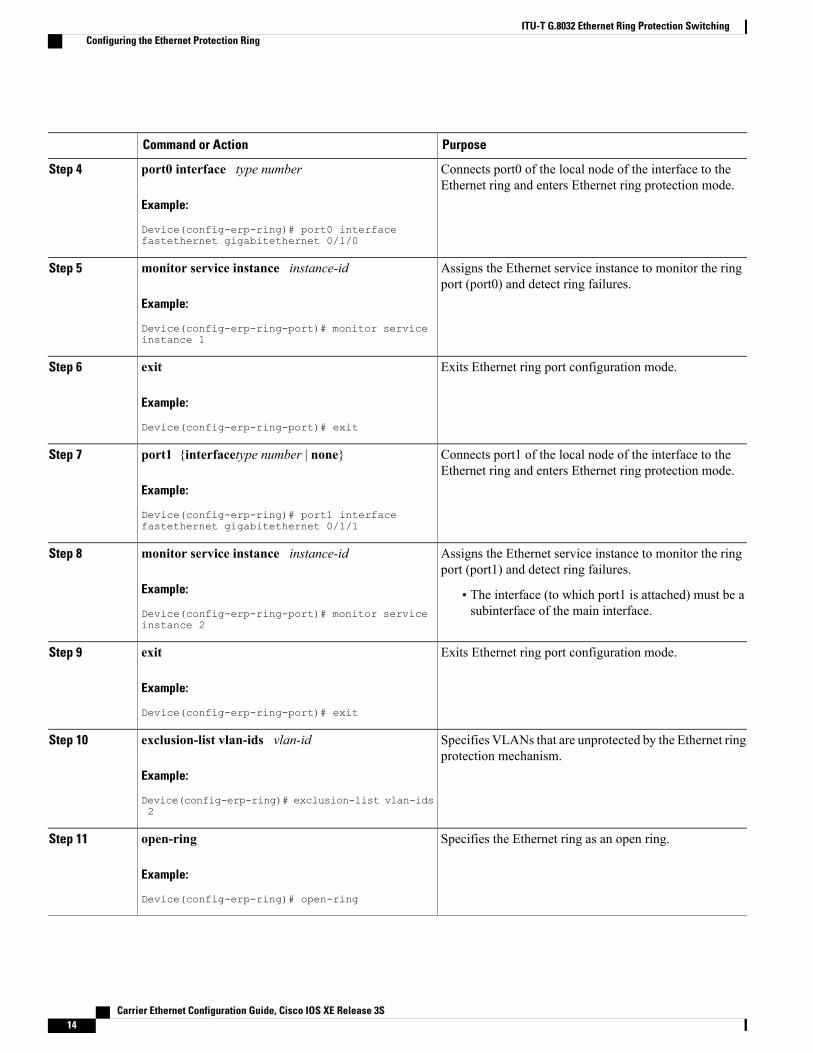
PurposeCommand or Action
Connects port0 of the local node of the interface to theEthernet ring and enters Ethernet ring protection mode.
port0 interface type number
Example:
Device(config-erp-ring)# port0 interfacefastethernet gigabitethernet 0/1/0
Step 4
Assigns the Ethernet service instance to monitor the ringport (port0) and detect ring failures.
monitor service instance instance-id
Example:
Device(config-erp-ring-port)# monitor serviceinstance 1
Step 5
Exits Ethernet ring port configuration mode.exit
Example:
Device(config-erp-ring-port)# exit
Step 6
Connects port1 of the local node of the interface to theEthernet ring and enters Ethernet ring protection mode.
port1 {interfacetype number | none}
Example:
Device(config-erp-ring)# port1 interfacefastethernet gigabitethernet 0/1/1
Step 7
Assigns the Ethernet service instance to monitor the ringport (port1) and detect ring failures.
monitor service instance instance-id
Example:
Device(config-erp-ring-port)# monitor serviceinstance 2
Step 8
• The interface (to which port1 is attached) must be asubinterface of the main interface.
Exits Ethernet ring port configuration mode.exit
Example:
Device(config-erp-ring-port)# exit
Step 9
Specifies VLANs that are unprotected by the Ethernet ringprotection mechanism.
exclusion-list vlan-ids vlan-id
Example:
Device(config-erp-ring)# exclusion-list vlan-ids2
Step 10
Specifies the Ethernet ring as an open ring.open-ring
Example:
Device(config-erp-ring)# open-ring
Step 11
Carrier Ethernet Configuration Guide, Cisco IOS XE Release 3S14
ITU-T G.8032 Ethernet Ring Protection SwitchingConfiguring the Ethernet Protection Ring
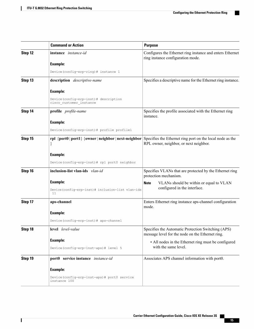
PurposeCommand or Action
Configures the Ethernet ring instance and enters Ethernetring instance configuration mode.
instance instance-id
Example:
Device(config-erp-ring)# instance 1
Step 12
Specifies a descriptive name for the Ethernet ring instance.description descriptive-name
Example:
Device(config-erp-inst)# descriptioncisco_customer_instance
Step 13
Specifies the profile associated with the Ethernet ringinstance.
profile profile-name
Example:
Device(config-erp-inst)# profile profile1
Step 14
Specifies the Ethernet ring port on the local node as theRPL owner, neighbor, or next neighbor.
rpl {port0 | port1} {owner | neighbor | next-neighbor}
Example:
Device(config-erp-inst)# rpl port0 neighbor
Step 15
Specifies VLANs that are protected by the Ethernet ringprotection mechanism.
inclusion-list vlan-ids vlan-id
Example:
Device(config-erp-inst)# inclusion-list vlan-ids11
Step 16
VLANs should be within or equal to VLANconfigured in the interface.
Note
Enters Ethernet ring instance aps-channel configurationmode.
aps-channel
Example:
Device(config-erp-inst)# aps-channel
Step 17
Specifies the Automatic Protection Switching (APS)message level for the node on the Ethernet ring.
level level-value
Example:
Device(config-erp-inst-aps)# level 5
Step 18
• All nodes in the Ethernet ring must be configuredwith the same level.
Associates APS channel information with port0.port0 service instance instance-id
Example:
Device(config-erp-inst-aps)# port0 serviceinstance 100
Step 19
Carrier Ethernet Configuration Guide, Cisco IOS XE Release 3S 15
ITU-T G.8032 Ethernet Ring Protection SwitchingConfiguring the Ethernet Protection Ring
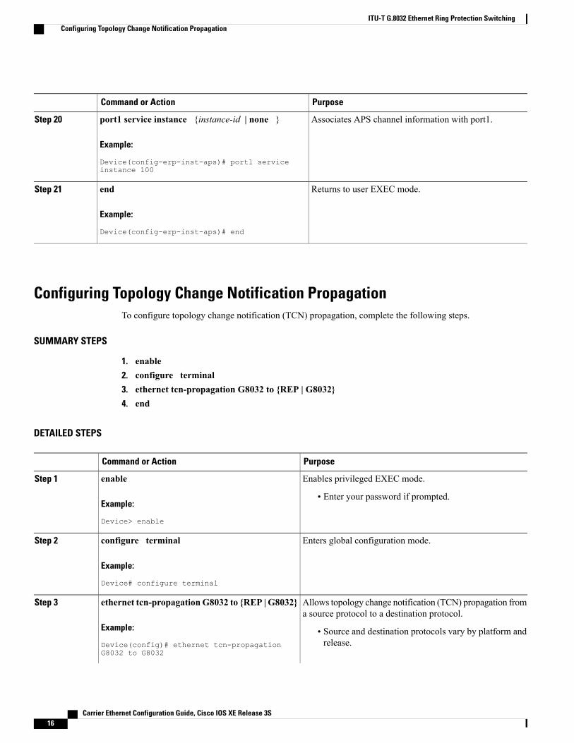
PurposeCommand or Action
Associates APS channel information with port1.port1 service instance {instance-id | none }
Example:
Device(config-erp-inst-aps)# port1 serviceinstance 100
Step 20
Returns to user EXEC mode.end
Example:
Device(config-erp-inst-aps)# end
Step 21
Configuring Topology Change Notification PropagationTo configure topology change notification (TCN) propagation, complete the following steps.
SUMMARY STEPS
1. enable2. configure terminal3. ethernet tcn-propagation G8032 to {REP | G8032}4. end
DETAILED STEPS
PurposeCommand or Action
Enables privileged EXEC mode.enableStep 1
Example:
Device> enable
• Enter your password if prompted.
Enters global configuration mode.configure terminal
Example:
Device# configure terminal
Step 2
Allows topology change notification (TCN) propagation froma source protocol to a destination protocol.
ethernet tcn-propagationG8032 to {REP | G8032}
Example:
Device(config)# ethernet tcn-propagationG8032 to G8032
Step 3
• Source and destination protocols vary by platform andrelease.
Carrier Ethernet Configuration Guide, Cisco IOS XE Release 3S16
ITU-T G.8032 Ethernet Ring Protection SwitchingConfiguring Topology Change Notification Propagation
PurposeCommand or Action
Returns to user EXEC mode.end
Example:
Device(config)# end
Step 4
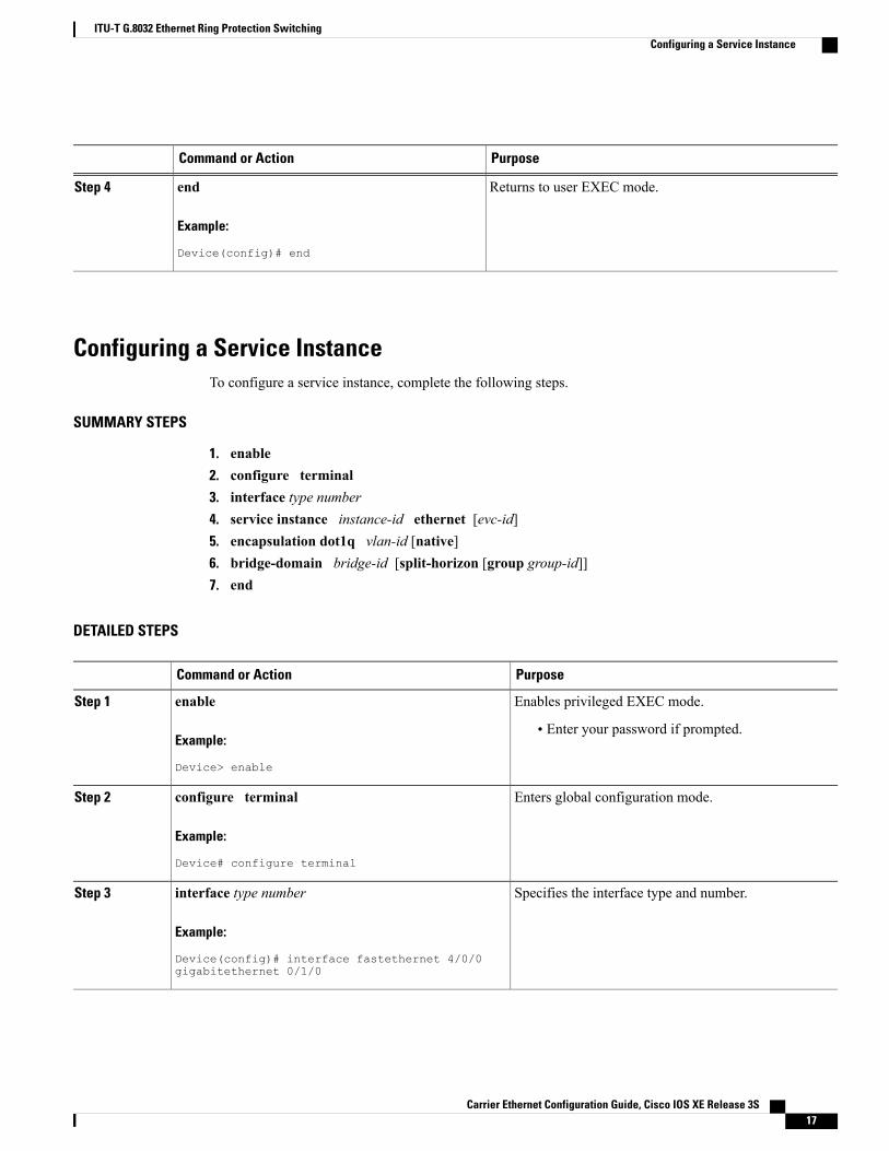
Configuring a Service InstanceTo configure a service instance, complete the following steps.
SUMMARY STEPS
1. enable2. configure terminal3. interface type number4. service instance instance-id ethernet [evc-id]5. encapsulation dot1q vlan-id [native]6. bridge-domain bridge-id [split-horizon [group group-id]]7. end
DETAILED STEPS
PurposeCommand or Action
Enables privileged EXEC mode.enableStep 1
Example:
Device> enable
• Enter your password if prompted.
Enters global configuration mode.configure terminal
Example:
Device# configure terminal
Step 2
Specifies the interface type and number.interface type number
Example:
Device(config)# interface fastethernet 4/0/0gigabitethernet 0/1/0
Step 3
Carrier Ethernet Configuration Guide, Cisco IOS XE Release 3S 17
ITU-T G.8032 Ethernet Ring Protection SwitchingConfiguring a Service Instance
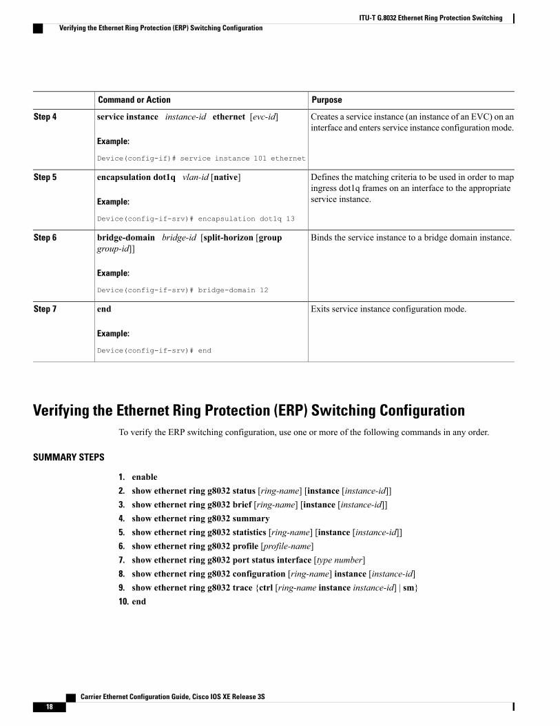
PurposeCommand or Action
Creates a service instance (an instance of an EVC) on aninterface and enters service instance configuration mode.
service instance instance-id ethernet [evc-id]
Example:
Device(config-if)# service instance 101 ethernet
Step 4
Defines the matching criteria to be used in order to mapingress dot1q frames on an interface to the appropriateservice instance.
encapsulation dot1q vlan-id [native]
Example:
Device(config-if-srv)# encapsulation dot1q 13
Step 5
Binds the service instance to a bridge domain instance.bridge-domain bridge-id [split-horizon [groupgroup-id]]
Step 6
Example:
Device(config-if-srv)# bridge-domain 12
Exits service instance configuration mode.end
Example:
Device(config-if-srv)# end
Step 7
Verifying the Ethernet Ring Protection (ERP) Switching ConfigurationTo verify the ERP switching configuration, use one or more of the following commands in any order.
SUMMARY STEPS
1. enable2. show ethernet ring g8032 status [ring-name] [instance [instance-id]]3. show ethernet ring g8032 brief [ring-name] [instance [instance-id]]4. show ethernet ring g8032 summary5. show ethernet ring g8032 statistics [ring-name] [instance [instance-id]]6. show ethernet ring g8032 profile [profile-name]7. show ethernet ring g8032 port status interface [type number]8. show ethernet ring g8032 configuration [ring-name] instance [instance-id]9. show ethernet ring g8032 trace {ctrl [ring-name instance instance-id] | sm}10. end
Carrier Ethernet Configuration Guide, Cisco IOS XE Release 3S18
ITU-T G.8032 Ethernet Ring Protection SwitchingVerifying the Ethernet Ring Protection (ERP) Switching Configuration
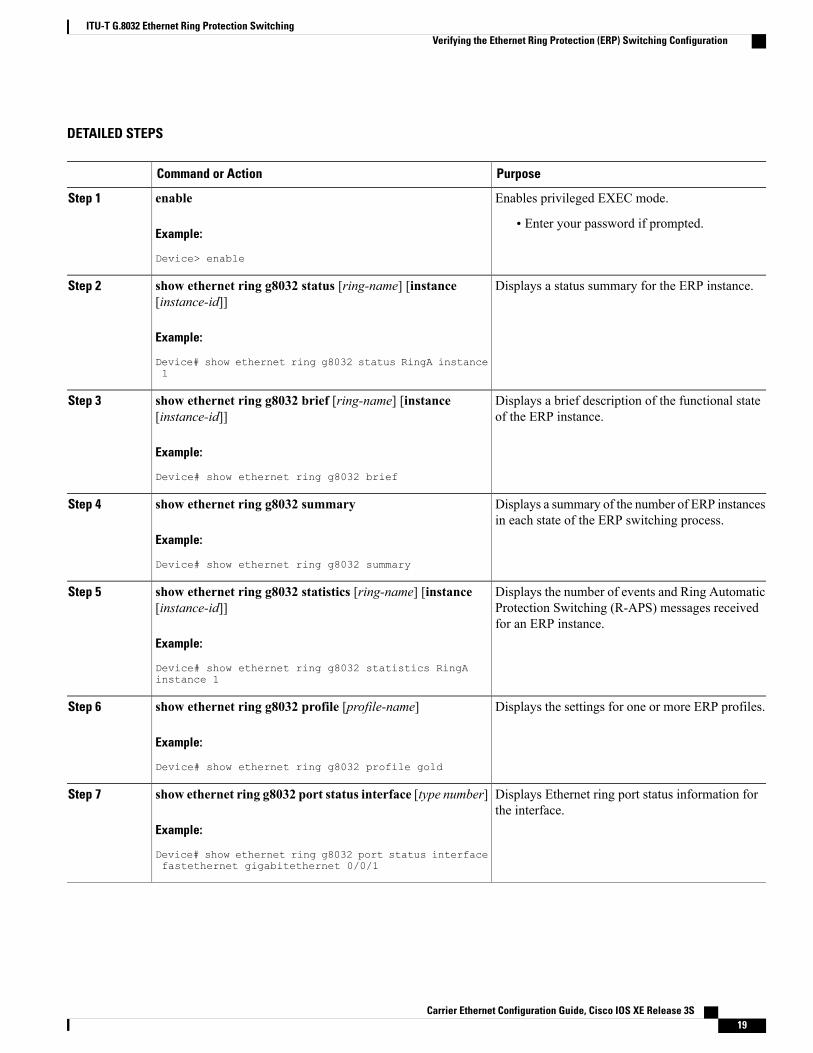
DETAILED STEPS
PurposeCommand or Action
Enables privileged EXEC mode.enableStep 1
Example:
Device> enable
• Enter your password if prompted.
Displays a status summary for the ERP instance.show ethernet ring g8032 status [ring-name] [instance[instance-id]]
Step 2
Example:
Device# show ethernet ring g8032 status RingA instance1
Displays a brief description of the functional stateof the ERP instance.
show ethernet ring g8032 brief [ring-name] [instance[instance-id]]
Example:
Device# show ethernet ring g8032 brief
Step 3
Displays a summary of the number of ERP instancesin each state of the ERP switching process.
show ethernet ring g8032 summary
Example:
Device# show ethernet ring g8032 summary
Step 4
Displays the number of events and Ring AutomaticProtection Switching (R-APS) messages receivedfor an ERP instance.
show ethernet ring g8032 statistics [ring-name] [instance[instance-id]]
Example:
Device# show ethernet ring g8032 statistics RingAinstance 1
Step 5
Displays the settings for one or more ERP profiles.show ethernet ring g8032 profile [profile-name]
Example:
Device# show ethernet ring g8032 profile gold
Step 6
Displays Ethernet ring port status information forthe interface.
show ethernet ring g8032 port status interface [type number]
Example:
Device# show ethernet ring g8032 port status interfacefastethernet gigabitethernet 0/0/1
Step 7
Carrier Ethernet Configuration Guide, Cisco IOS XE Release 3S 19
ITU-T G.8032 Ethernet Ring Protection SwitchingVerifying the Ethernet Ring Protection (ERP) Switching Configuration
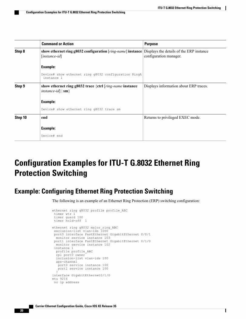
PurposeCommand or Action
Displays the details of the ERP instanceconfiguration manager.
show ethernet ring g8032 configuration [ring-name] instance[instance-id]
Example:
Device# show ethernet ring g8032 configuration RingAinstance 1
Step 8
Displays information about ERP traces.show ethernet ring g8032 trace {ctrl [ring-name instanceinstance-id] | sm}
Step 9
Example:
Device# show ethernet ring g8032 trace sm
Returns to privileged EXEC mode.end
Example:
Device# end
Step 10
Configuration Examples for ITU-T G.8032 Ethernet RingProtection Switching
Example: Configuring Ethernet Ring Protection SwitchingThe following is an example of an Ethernet Ring Protection (ERP) switching configuration:
ethernet ring g8032 profile profile_ABCtimer wtr 1timer guard 100timer hold-off 1
ethernet ring g8032 major_ring_ABCexclusion-list vlan-ids 1000port0 interface FastEthernet GigabitEthernet 0/0/1monitor service instance 103port1 interface FastEthernet GigabitEthernet 0/1/0monitor service instance 102instance 1profile profile_ABCrpl port0 ownerinclusion-list vlan-ids 100aps-channelport0 service instance 100port1 service instance 100!
interface GigabitEthernet0/1/0mtu 9216no ip address
Carrier Ethernet Configuration Guide, Cisco IOS XE Release 3S20
ITU-T G.8032 Ethernet Ring Protection SwitchingConfiguration Examples for ITU-T G.8032 Ethernet Ring Protection Switching
negotiation autoservice instance trunk 1 ethernetencapsulation dot1q 60-61rewrite ingress tag pop 1 symmetricbridge-domain from-encapsulation
!!
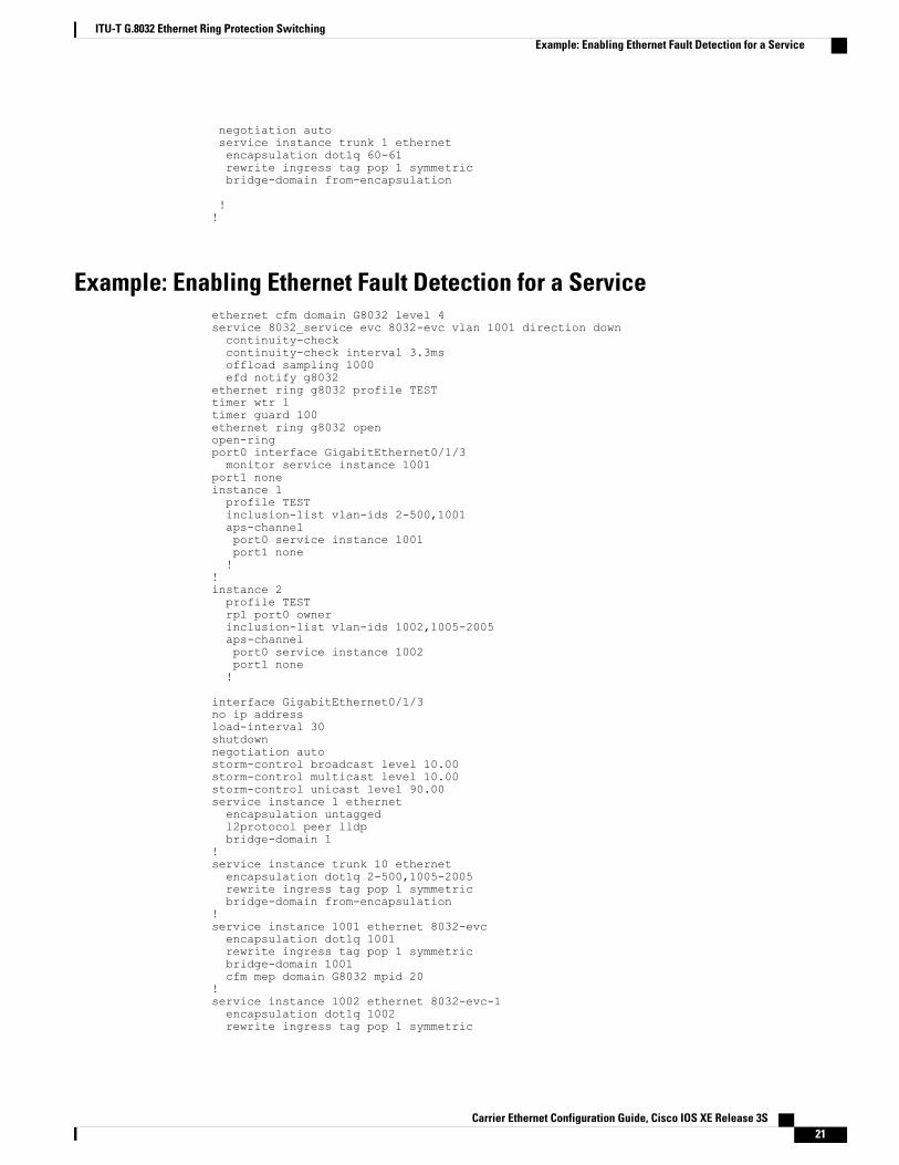
Example: Enabling Ethernet Fault Detection for a Serviceethernet cfm domain G8032 level 4service 8032_service evc 8032-evc vlan 1001 direction downcontinuity-checkcontinuity-check interval 3.3msoffload sampling 1000efd notify g8032
ethernet ring g8032 profile TESTtimer wtr 1timer guard 100ethernet ring g8032 openopen-ringport0 interface GigabitEthernet0/1/3monitor service instance 1001
port1 noneinstance 1profile TESTinclusion-list vlan-ids 2-500,1001aps-channelport0 service instance 1001port1 none!
!instance 2profile TESTrpl port0 ownerinclusion-list vlan-ids 1002,1005-2005aps-channelport0 service instance 1002port1 none!
interface GigabitEthernet0/1/3no ip addressload-interval 30shutdownnegotiation autostorm-control broadcast level 10.00storm-control multicast level 10.00storm-control unicast level 90.00service instance 1 ethernetencapsulation untaggedl2protocol peer lldpbridge-domain 1
!service instance trunk 10 ethernetencapsulation dot1q 2-500,1005-2005rewrite ingress tag pop 1 symmetricbridge-domain from-encapsulation
!service instance 1001 ethernet 8032-evcencapsulation dot1q 1001rewrite ingress tag pop 1 symmetricbridge-domain 1001cfm mep domain G8032 mpid 20
!service instance 1002 ethernet 8032-evc-1encapsulation dot1q 1002rewrite ingress tag pop 1 symmetric
Carrier Ethernet Configuration Guide, Cisco IOS XE Release 3S 21
ITU-T G.8032 Ethernet Ring Protection SwitchingExample: Enabling Ethernet Fault Detection for a Service
bridge-domain 1002!End
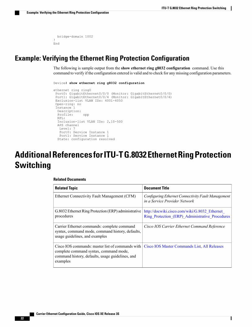
Example: Verifying the Ethernet Ring Protection ConfigurationThe following is sample output from the show ethernet ring g8032 configuration command. Use thiscommand to verify if the configuration entered is valid and to check for anymissing configuration parameters.
Device# show ethernet ring g8032 configuration
ethernet ring ring0Port0: GigabitEthernet0/0/0 (Monitor: GigabitEthernet0/0/0)Port1: GigabitEthernet0/0/4 (Monitor: GigabitEthernet0/0/4)Exclusion-list VLAN IDs: 4001-4050Open-ring: noInstance 1Description:Profile: oppRPL:Inclusion-list VLAN IDs: 2,10-500APS channelLevel: 7Port0: Service Instance 1Port1: Service Instance 1State: configuration resolved
Additional References for ITU-T G.8032 Ethernet Ring ProtectionSwitching
Related Documents
Document TitleRelated Topic
Configuring Ethernet Connectivity FaultManagementin a Service Provider Network
Ethernet Connectivity Fault Management (CFM)
http://docwiki.cisco.com/wiki/G.8032_Ethernet_Ring_Protection_(ERP)_Administrative_Procedures
G.8032 Ethernet Ring Protection (ERP) administrativeprocedures
Cisco IOS Carrier Ethernet Command ReferenceCarrier Ethernet commands: complete commandsyntax, command mode, command history, defaults,usage guidelines, and examples
Cisco IOS Master Commands List, All ReleasesCisco IOS commands: master list of commands withcomplete command syntax, command mode,command history, defaults, usage guidelines, andexamples
Carrier Ethernet Configuration Guide, Cisco IOS XE Release 3S22
ITU-T G.8032 Ethernet Ring Protection SwitchingExample: Verifying the Ethernet Ring Protection Configuration
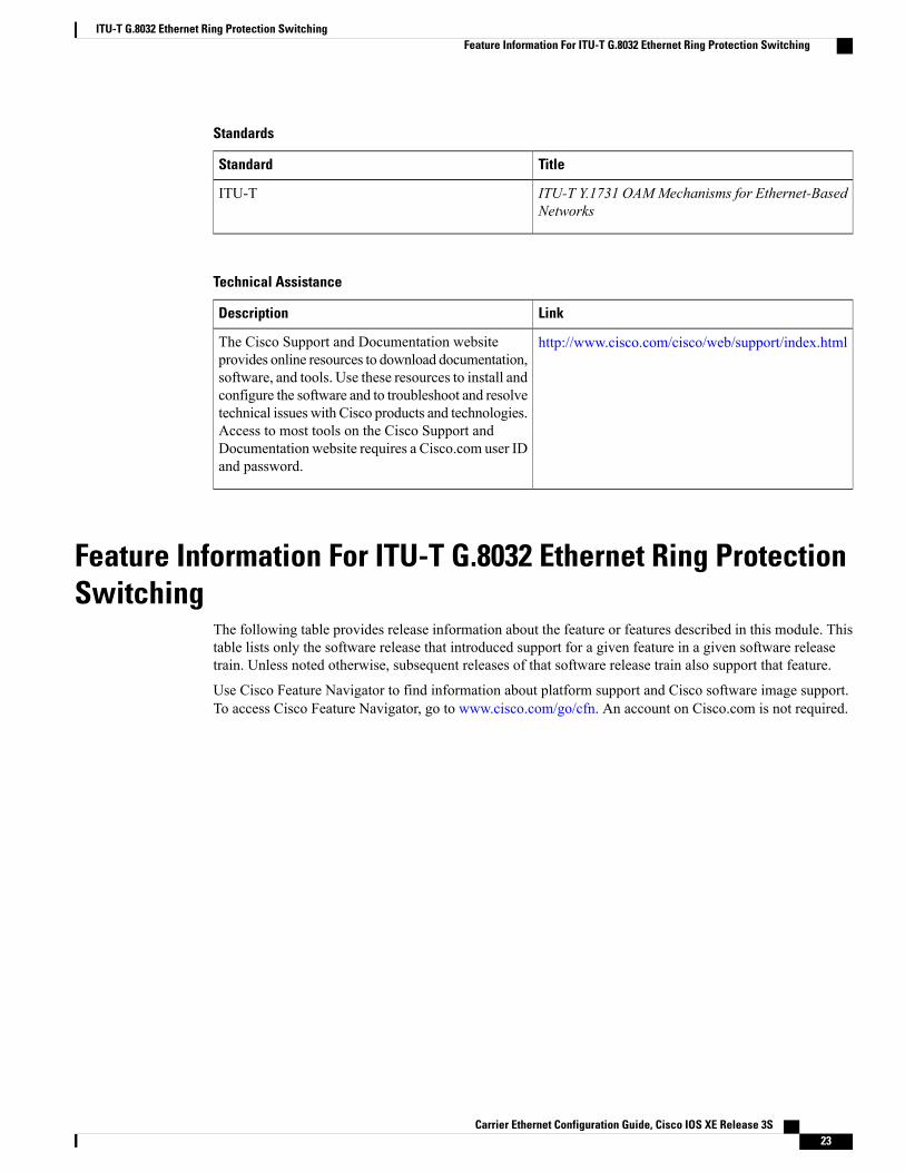
Standards
TitleStandard
ITU-T Y.1731 OAMMechanisms for Ethernet-BasedNetworks
ITU-T
Technical Assistance
LinkDescription
http://www.cisco.com/cisco/web/support/index.htmlThe Cisco Support and Documentation websiteprovides online resources to download documentation,software, and tools. Use these resources to install andconfigure the software and to troubleshoot and resolvetechnical issues with Cisco products and technologies.Access to most tools on the Cisco Support andDocumentation website requires a Cisco.com user IDand password.
Feature Information For ITU-T G.8032 Ethernet Ring ProtectionSwitching
The following table provides release information about the feature or features described in this module. Thistable lists only the software release that introduced support for a given feature in a given software releasetrain. Unless noted otherwise, subsequent releases of that software release train also support that feature.
Use Cisco Feature Navigator to find information about platform support and Cisco software image support.To access Cisco Feature Navigator, go to www.cisco.com/go/cfn. An account on Cisco.com is not required.
Carrier Ethernet Configuration Guide, Cisco IOS XE Release 3S 23
ITU-T G.8032 Ethernet Ring Protection SwitchingFeature Information For ITU-T G.8032 Ethernet Ring Protection Switching
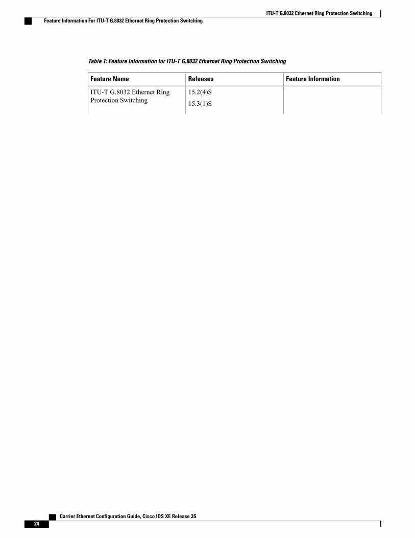
Table 1: Feature Information for ITU-T G.8032 Ethernet Ring Protection Switching
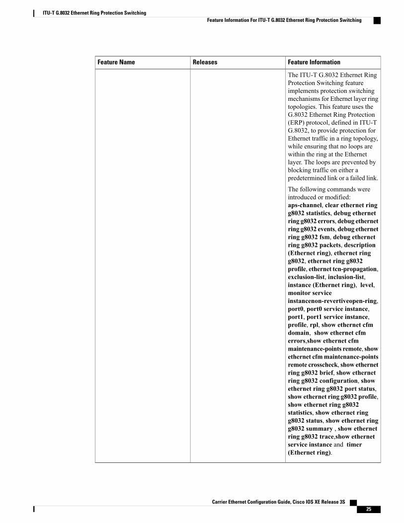
Feature InformationReleasesFeature Name
15.2(4)S
15.3(1)S
ITU-T G.8032 Ethernet RingProtection Switching
Carrier Ethernet Configuration Guide, Cisco IOS XE Release 3S24
ITU-T G.8032 Ethernet Ring Protection SwitchingFeature Information For ITU-T G.8032 Ethernet Ring Protection Switching
Feature InformationReleasesFeature Name
The ITU-T G.8032 Ethernet RingProtection Switching featureimplements protection switchingmechanisms for Ethernet layer ringtopologies. This feature uses theG.8032 Ethernet Ring Protection(ERP) protocol, defined in ITU-TG.8032, to provide protection forEthernet traffic in a ring topology,while ensuring that no loops arewithin the ring at the Ethernetlayer. The loops are prevented byblocking traffic on either apredetermined link or a failed link.
The following commands wereintroduced or modified:aps-channel, clear ethernet ringg8032 statistics, debug ethernetring g8032 errors, debug ethernetring g8032 events, debug ethernetring g8032 fsm, debug ethernetring g8032 packets, description(Ethernet ring), ethernet ringg8032, ethernet ring g8032profile, ethernet tcn-propagation,exclusion-list, inclusion-list,instance (Ethernet ring), level,monitor serviceinstancenon-revertiveopen-ring,port0, port0 service instance,port1, port1 service instance,profile, rpl, show ethernet cfmdomain, show ethernet cfmerrors,show ethernet cfmmaintenance-points remote, showethernet cfmmaintenance-pointsremote crosscheck, show ethernetring g8032 brief, show ethernetring g8032 configuration, showethernet ring g8032 port status,show ethernet ring g8032 profile,show ethernet ring g8032statistics, show ethernet ringg8032 status, show ethernet ringg8032 summary , show ethernetring g8032 trace,show ethernetservice instance and timer(Ethernet ring).
Carrier Ethernet Configuration Guide, Cisco IOS XE Release 3S 25
ITU-T G.8032 Ethernet Ring Protection SwitchingFeature Information For ITU-T G.8032 Ethernet Ring Protection Switching

Carrier Ethernet Configuration Guide, Cisco IOS XE Release 3S26
ITU-T G.8032 Ethernet Ring Protection SwitchingFeature Information For ITU-T G.8032 Ethernet Ring Protection Switching