Embed Size (px)
Citation preview
ITU-T Q13/15activity and its relation with the leap second
Jean-Loup Ferrant, ITU-T Q13/15 Rapporteur
Calnex solutions
2
Q13/15 Network synchronization and time distribution performance Q13 has already studied network
synchronization issues related to PDH and SDH from 1988 until 2000, and to OTN in 2001-2004 and 2008-2012 Study Periods. This question has also started studying the network synchronization issues related to packet networks with focus on mobile network needs from 2004 until 2012. Continuing effort needs to be put into the study of synchronization issues in packet based networks.
Need for synchronization
3
In the 1970’s digital switches had to be synchronized (syntonized in fact) to prevent slips. PDH links 2.048 and 1544 Mbits could transport timing between switches In the 1990’s SDH &SONET networks provided a new synchronization network. In the 1990s, NTP was condisered accurate enough for the existing applications The OTN (Optical Transport Network) specified at the begining of the 2000’s was not defined to be a new synchronization network, but simply to be transparent to the existing SDH one.
Need for synchronization
4
The evolution of telecom networks toward packet networks has generated a new need to transport a reference frequency through packet networks for FDD networks requiring 50ppb accuracy -The evolution of mobile networks toward TDD techniques added a new requirement for the transport of time with an accuracy of 1.5 µs
In the 1990’s the emerging mobile networks were specified to operate within a 50 ppb frequency accuracy -the reference timing was transported with the data via synchronized 2Mbits signals
Q13 milestones
5
Until 2003 transport of frequency over -PDH, SDH, OTN 2003-2013 transport of frequency over packet networks via -CES - synchronous Ethernet - IEEE 1588 V2 2011-2013 transport of phase and time over packet networks via IEEE 1588 V2 -work still ongoing
synchronous Ethernet
6
-based on SDH clocks and network architecture
-totally compatible with SDH *SyncE links and SDH links can be chained *a synchronization network may have both SDH and SyncE network elements -But it does not transfer time * could be done using packets with SSM *but it was preferred to use the new IEEE 1588
SyncE equipment
7
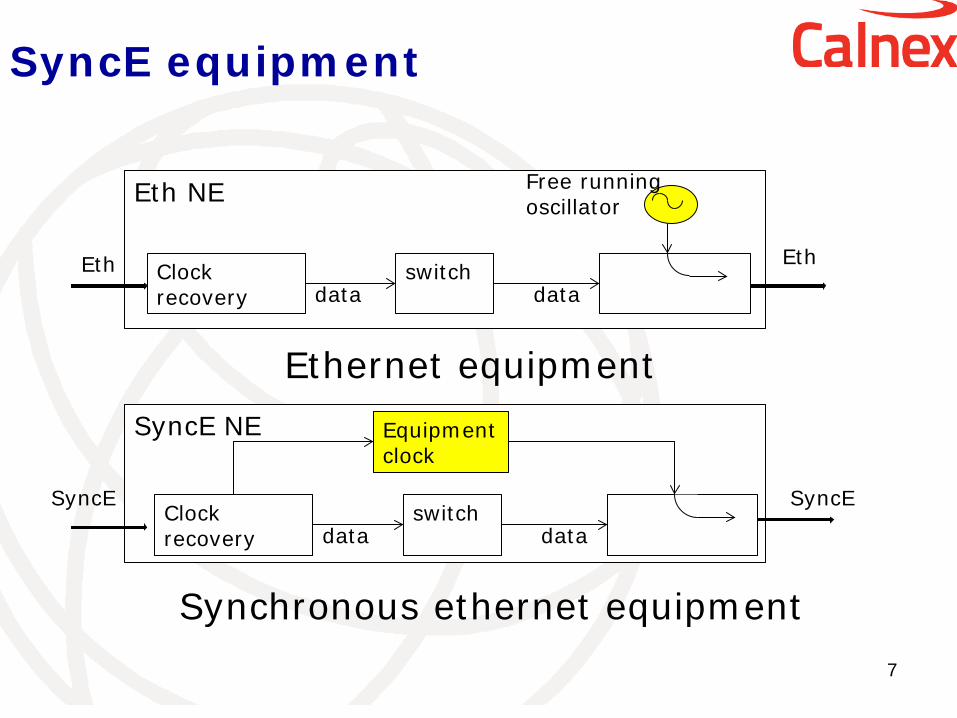
Eth NE
Clock recovery
switch data data
Free running oscillator
Eth Eth
SyncE NE
Clock recovery
switch data data
Equipment clock
SyncE SyncE
Ethernet equipment
Synchronous ethernet equipment
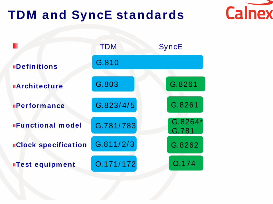
TDM SyncE
Definitions Architecture Performance Functional model Clock specification Test equipment
G.810
G.781/783 G.8264* G.781
G.8262
G.8261
G.8261 G.803
G.811/2/3
O.171/172
G.823/4/5
O.174
TDM and SyncE standards
Packet networks and PDV
In packet networks switches/routers store packets in buffers as they arrive and transmit them when possible in the outgoing link The transfer delay through a switch/router highly depends on the traffic and the design of the switch/router implementation This packet delay variation, PDV, degrades the quality of timing. PDV may reach tens or hundreds of µs in a packet network, to be compared with 1.5µs accuracy requested for TDD mobile applications
9
IEEE Std 1588TM - 2008
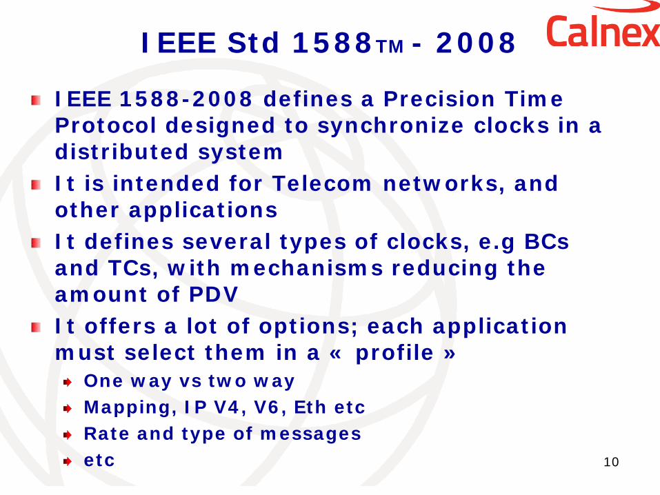
IEEE 1588-2008 defines a Precision Time Protocol designed to synchronize clocks in a distributed system It is intended for Telecom networks, and other applications It defines several types of clocks, e.g BCs and TCs, with mechanisms reducing the amount of PDV It offers a lot of options; each application must select them in a « profile »
One way vs two way Mapping, IP V4, V6, Eth etc Rate and type of messages etc
10
transport of frequency over packet networks using IEEE-1588
11
Q13 decided to study a first « end to end » profile where: -the transport of frequency is done via IEEE 1588 messages -The IEEE 1588 Grand Master delivers the PTP messages -The slave clock extracts the timing from the PTP messages and delivers the frequency - Equipment located between the grand Master and the Slave clock are basic switches/routers , unaware of IEEE 1588, providing a solution for existing packet networks
12
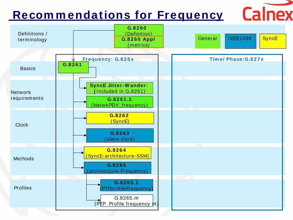
G.8265.1 (PTPprofileFrequency)
Basics
Clock
Methods
Profiles
Frequency: G.826x Time/Phase:G.827x
G.8265.m (PTP Profile frequency m)
G.8261.1 (NetwkPDV_frequency)
Network requirements
SyncE Jitter-Wander: (Included in G.8261)
G.8261
G.8262 (SyncE)
G.8264 (SyncE-architecture-SSM)
G.8265 (architecture-Frequency)
Definitions / terminology
G.8260 (Definition)
G.8260 AppI (metrics)
Recommendations for Frequency
SyncE
General
G.8263 (slave clock)
IEEE1588
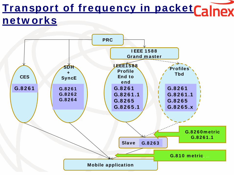
Transport of frequency in packet networks
IEEE1588
Profile End to
end
Profiles Tbd
IEEE 1588 Grand master
PRC
SDH
+ SyncE
G.8261 G.8262 G.8264
Slave
Mobile application
G.810 metric, ..
G.8260metric G.8261.1
G.8263
CES
G.8261 G.8261 G.8261.1 G.8265 G.8265.1
G.8261 G.8261.1 G.8265 G.8265.x
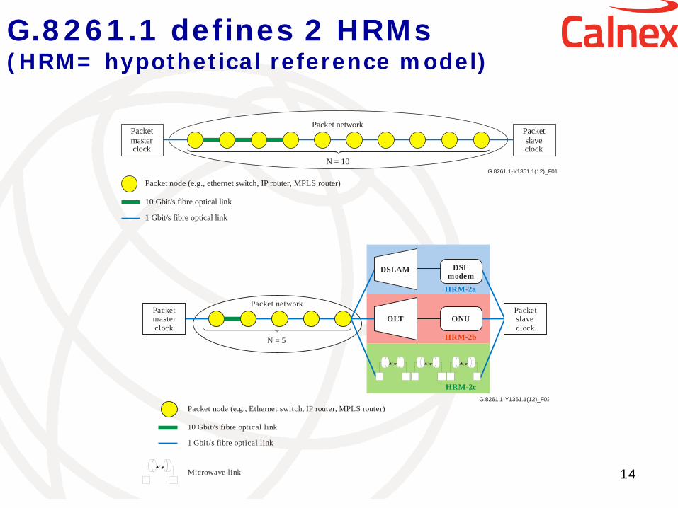
G.8261.1 defines 2 HRMs (HRM= hypothetical reference model)
14
G.8261.1-Y1361.1(12)_F02
Packetmasterclock
Packet network
N = 5
Packet node (e.g., Ethernet switch, IP router, MPLS router)
10 Gbit/s fibre optical link
1 Gbit/s fibre optical link
Microwave link
Packetslaveclock
DSLAM DSLmodem
HRM-2a
HRM-2b
HRM-2c
ONUOLT
G.8261.1-Y1361.1(12)_F01
Packetmasterclock
Packet network
N = 10
Packetslaveclock
Packet node (e.g., ethernet switch, IP router, MPLS router)
10 Gbit/s fibre optical link
1 Gbit/s fibre optical link
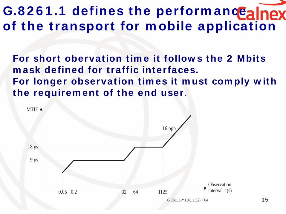
G.8261.1 defines the performance of the transport for mobile application
15 G.8261.1-Y.1361.1(12)_F04
MTIE
18 sμ
9 sμ
0.05 0.2 32 64 1125
16 ppb
Observationinterval (s)τ
For short obervation time it follows the 2 Mbits mask defined for traffic interfaces. For longer observation times it must comply with the requirement of the end user.
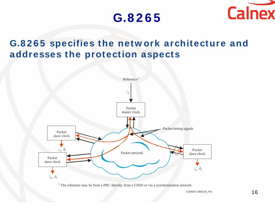
G.8265
16
F +out 1δ
i
Packet network
NetworkNetwork
F
a) The reference may be from a PRC directly, from a GNSS or via a synchronization network
Packet timing signalsPacket
slave clock
Packetmaster clock
Referencea)
F +out 3δ
F +out 2δ
Packetslave clock
Packetslave clock
G.8265/Y.1365(10)_F01
G.8265 specifies the network architecture and addresses the protection aspects
G.8265.1
17
G.8265.1 specifies the profile for frequency distribution without timing support from the network (PTP messages not processed in equipments between master and slave) Mapping: IP Mode: one-way or two-way Unicast mode Message rates Protection: definition of an alternate BMCA (Best Master Clock Algorithm)
G.SUPP
18
Extensive simulations were done to validate the specifications done for the transport of frequency using IEEE 1588. A supplement called G.SUPPxx will present the simulation results.
transport of phase and time over packet networks using IEEE-1588
19
Transport of time implies a two-way mode to take into account the transport delay between the the master clock and the slave clock. IEEE 1588 is based on TAI time but it also provides an information to get UTC, called the « currentUtcOffset »
IEEE 1588 propagation delay
20
t1 t2
t3 t4
master slave
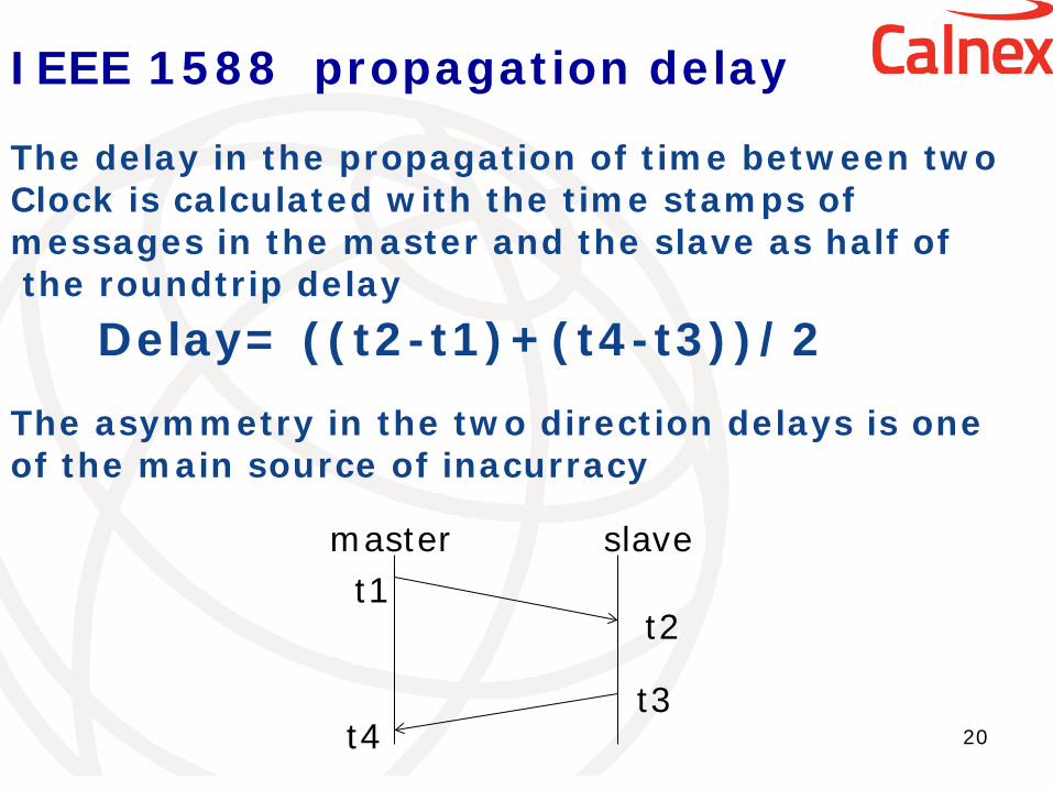
The delay in the propagation of time between two Clock is calculated with the time stamps of messages in the master and the slave as half of the roundtrip delay
Delay= ((t2-t1)+(t4-t3))/2
The asymmetry in the two direction delays is one of the main source of inacurracy
21
G.8265.1 (PTPprofileFrequency)
G.8275.1 (PTPprofile1Time/phase)
Basics
Clock
Methods
Profiles
Frequency: G.826x Time/Phase:G.827x
G.8265.m (PTP Profile frequency m)
G.8261.1 (NetwkPDV_frequency)
G.8271.1 (NetwkPDV_time/phase Network
requirements
SyncE Jitter-Wander: (Included in G.8261)
G.8261
G.8271
G.8272 PRTC
G.8273
G.8275 (architecture-time)
G.8262 (SyncE)
G.8264 (SyncE-architecture-SSM)
G.8265 (architecture-Frequency)
G.8275.2 (PTPprofile2Time/phase )
G.8271.2(profile2)
Definitions / terminology
G.8260 (Definition)
73.1 GM
73.2 BC
73.3 TC
G.8260 AppI (metrics)
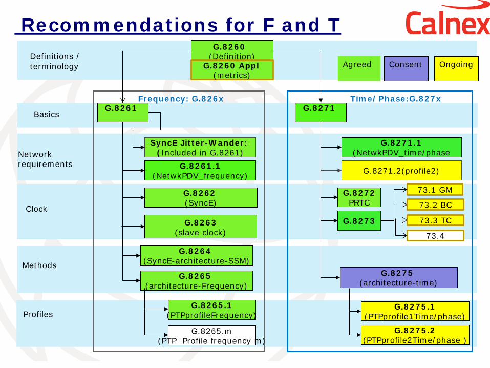
Recommendations for F and T
Ongoing
Agreed
G.8263 (slave clock) 73.4
Consent
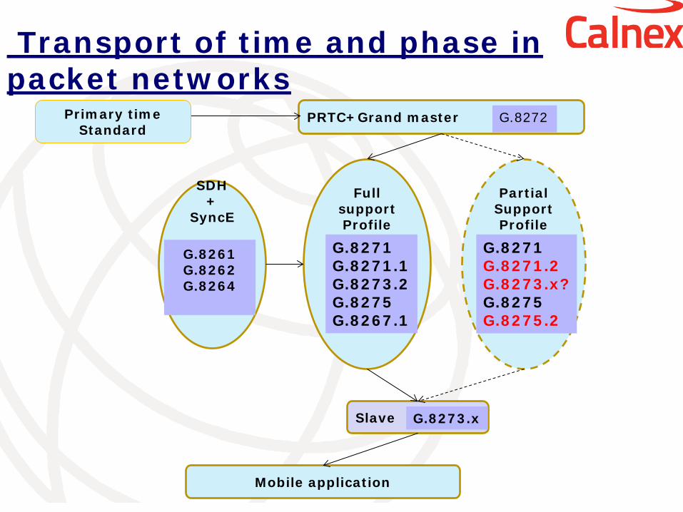
Transport of time and phase in packet networks
Full
support Profile
Partial Support Profile
PRTC+Grand master
SDH
+ SyncE
G.8261 G.8262 G.8264
Slave
Mobile application
G.8273.x
G.8271 G.8271.1 G.8273.2 G.8275 G.8267.1
Primary time Standard
G.8272
G.8271 G.8271.2 G.8273.x? G.8275 G.8275.2
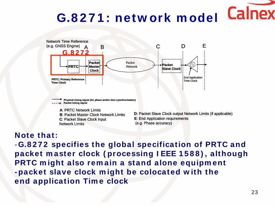
G.8271: network model
23
E: End Application requirements(e.g. Phase accuracy)
Packet Slave Clock
PRTC; Primary ReferenceTime Clock
End ApplicationTime Clock
Packet Network
C: Packet Slave Clock input Network Limits
PRTC
D: Packet Slave Clock output Network Limits (if applicable)A: PRTC Network Limits
Network Time Reference(e.g. GNSS Engine) A C D E
PacketMasterClock
Physical timing signal (for phase and/or time synchronization)Packet timing signal
B
B: Packet Master Clock Network LimitsE: End Application requirements(e.g. Phase accuracy)
Packet Slave Clock
PRTC; Primary ReferenceTime Clock
End ApplicationTime Clock
Packet Network
C: Packet Slave Clock input Network Limits
PRTC
D: Packet Slave Clock output Network Limits (if applicable)A: PRTC Network Limits
Network Time Reference(e.g. GNSS Engine) A C D E
PacketMasterClock
Physical timing signal (for phase and/or time synchronization)Packet timing signal
B
B: Packet Master Clock Network Limits
G.8272
Note that: -G.8272 specifies the global specification of PRTC and packet master clock (processing IEEE 1588), although PRTC might also remain a stand alone equipment -packet slave clock might be colocated with the end application Time clock
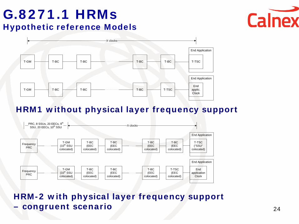
G.8271.1 HRMs Hypothetic reference Models
24
T-GM T-BC T-BC T-BC T-TSC
N clocks
End Application
End Application
T-BCT-GM T-BC T-BC T-BC T-TSC
End applic. Clock
T-GM(10th SSU colocated)
T-BC(EEC
colocated)
T-BC(EEC
colocated)
T-BC(EEC
colocated)
T-TSC(EEC
colocated)
N clocks
Frequency PRC
End Application
End application
Clock
T-GM(10th SSU colocated)
T-BC(EEC
colocated)
T-BC(EEC
colocated)
T-BC(EEC
colocated)
T-BC(EEC
colocated)
Frequency PRC
End Application
T-TSC("SSU"
colocated)
PRC, 8 SSUs, 20 EECs, 9th SSU, 20 EECs, 10th SSU
HRM1 without physical layer frequency support
HRM-2 with physical layer frequency support – congruent scenario
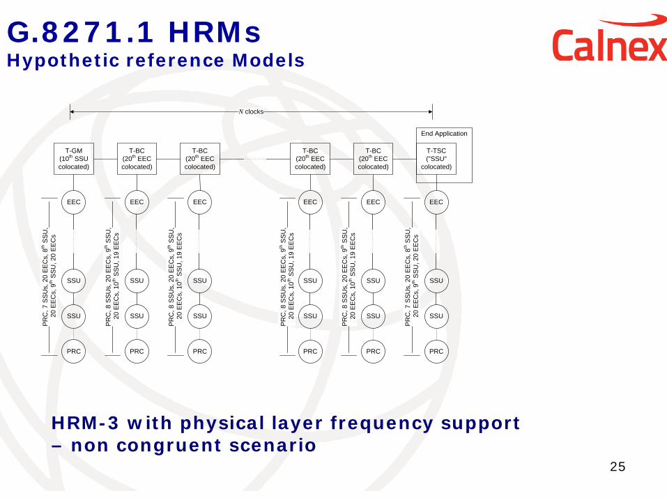
G.8271.1 HRMs Hypothetic reference Models
25
T-GM(10th SSU colocated)
T-BC(20th EEC colocated)
T-BC(20th EEC colocated)
T-BC(20th EEC colocated)
T-BC(20th EEC colocated)
N clocks
PRC
SSU
SSU
EEC
PRC
SSU
SSU
EEC
PRC
SSU
SSU
EEC
PRC
SSU
SSU
EEC
PRC
SSU
SSU
EEC
PR
C, 8
SS
Us,
20
EE
Cs,
9th S
SU
, 2
0 E
EC
s, 1
0th S
SU
, 19
EE
Cs
PR
C, 7
SS
Us,
20
EE
Cs,
8th S
SU
, 2
0 E
EC
s, 9
th S
SU
, 20
EE
Cs
PR
C, 8
SS
Us,
20
EE
Cs,
9th S
SU
, 2
0 E
EC
s, 1
0th S
SU
, 19
EE
Cs
PR
C, 8
SS
Us,
20
EE
Cs,
9th S
SU
, 2
0 E
EC
s, 1
0th S
SU
, 19
EE
Cs
PR
C, 8
SS
Us,
20
EE
Cs,
9th S
SU
, 2
0 E
EC
s, 1
0th S
SU
, 19
EE
Cs
PRC
SSU
SSU
EEC
PR
C, 7
SS
Us,
20
EE
Cs,
8th S
SU
, 2
0 E
EC
s, 9
th S
SU
, 20
EE
Cs
End Application
T-TSC("SSU"
colocated)
HRM-3 with physical layer frequency support – non congruent scenario
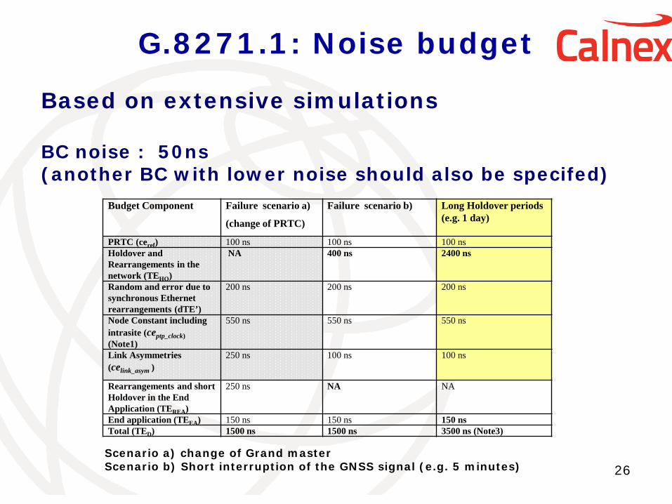
G.8271.1: Noise budget
26
Budget Component Failure scenario a)
(change of PRTC)
Failure scenario b) Long Holdover periods (e.g. 1 day)
PRTC (ceref) 100 ns 100 ns 100 ns Holdover and Rearrangements in the network (TEHO)
NA 400 ns 2400 ns
Random and error due to synchronous Ethernet rearrangements (dTE’)
200 ns 200 ns 200 ns
Node Constant including intrasite (ceptp_clock) (Note1)
550 ns 550 ns 550 ns
Link Asymmetries (celink_asym )
250 ns 100 ns 100 ns
Rearrangements and short Holdover in the End Application (TEREA)
250 ns NA NA
End application (TEEA) 150 ns 150 ns 150 ns Total (TED) 1500 ns 1500 ns 3500 ns (Note3)
Scenario a) change of Grand master Scenario b) Short interruption of the GNSS signal (e.g. 5 minutes)
Based on extensive simulations BC noise : 50ns (another BC with lower noise should also be specifed)
G.8271.2 HRM for the partial support profile
27
This HRM is under definition The basic of this HRM is to have -1588 unaware equipments -Might have Boundary clocks to filter PDV generated by 1588 unaware Nes -numbers of NEs: to be defined
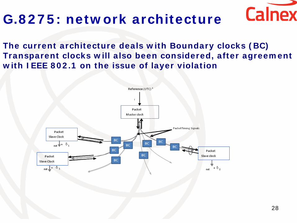
G.8275: network architecture
28
The current architecture deals with Boundary clocks (BC) Transparent clocks will also been considered, after agreement with IEEE 802.1 on the issue of layer violation
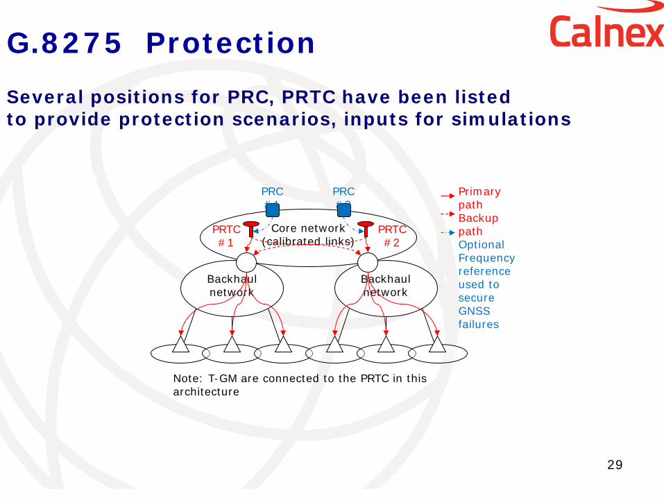
G.8275 Protection
29
Core network (calibrated links)
PRTC #2
Backhaul network
Backhaul network
PRC #1
PRTC #1
PRC #2
Primary path Backup path Optional Frequency reference used to secure GNSS failures
Note: T-GM are connected to the PRTC in this architecture
Several positions for PRC, PRTC have been listed to provide protection scenarios, inputs for simulations
Interest of Q13 in the leap second process
30
Q13 is responsible for the transport of time to end users, but is not involved in the applications which need time Q13 does not need time information for operating the transport network Q13 transports TAI from the PRTC to the end user via IEEE 1588 IEEE 1588 provides an information on the offset between TAI and UTC
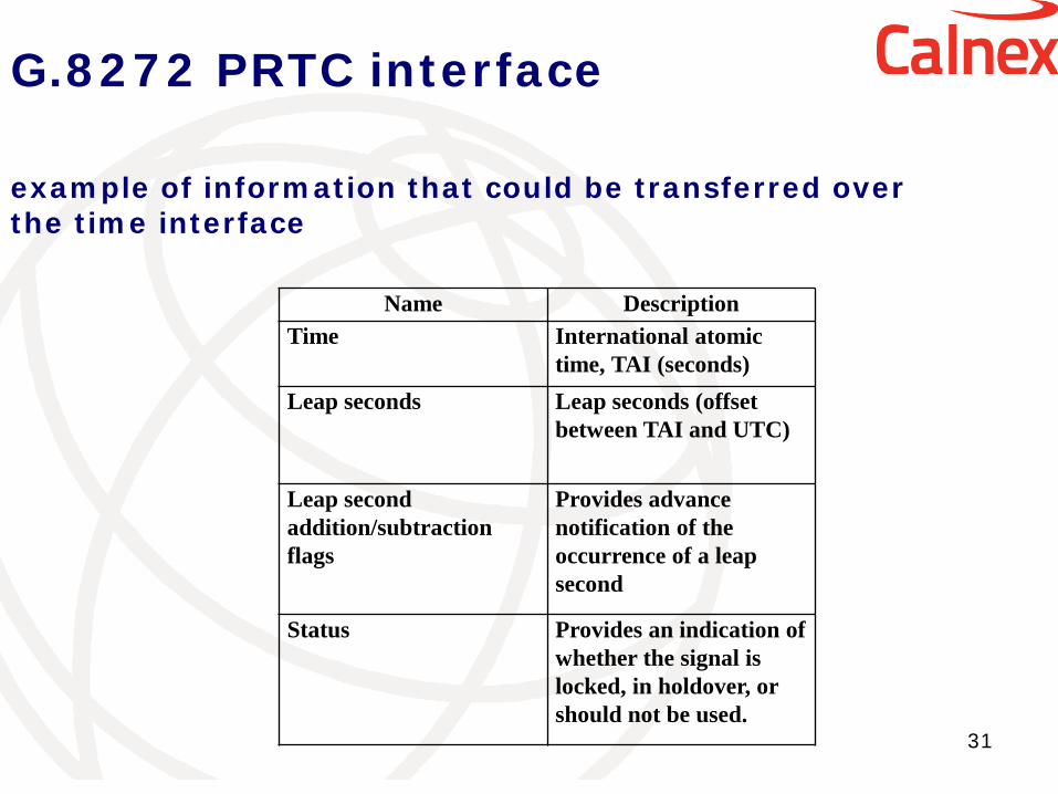
G.8272 PRTC interface
31
Name Description Time International atomic
time, TAI (seconds) Leap seconds Leap seconds (offset
between TAI and UTC)
Leap second addition/subtraction flags
Provides advance notification of the occurrence of a leap second
Status Provides an indication of whether the signal is locked, in holdover, or should not be used.
example of information that could be transferred over the time interface
Conclusion
32
- All processes involved in the transport of time can deliver TAI and UTC, as they have implemented some software to handle leap seconds, i.e.
-GPS receivers, PRTC -IEEE 1588 protocol -Preservation or removal of leap seconds is not an issue for Q13 - Current « Q13 network » is compatible with UTC - Divergence TAI vs UTC is no problem, for Q13 -But any modification in the leap second process will jeopardize the delivery of UTC at the end application, as it would require modification of equipments and protocols

33
http://www.itu.int/ITU-T/recommendations/index.aspx?ser=G
Where to get the recommendations?

A GIANT LEAP IN 1588V2 PTP MEASUREMENTS
www.calnexsol.com Company Confident ial
Jean-Loup Ferrant [email protected]
Thank You